FOR BRUSH TYPE 4 - BVE Cornwall
20
BRITISH RAILWAYS - EASTERN REGION FAULTS CHART FOR BRUSH T Y P E 4 LOCOMOTIVES Staff Training School Motive Power Section ILFORD DUP:KX: 209/66 January, 1966
Transcript of FOR BRUSH TYPE 4 - BVE Cornwall
BRITISH RAILWAYS - EASTERN REGION
FAULTS CHART
FOR
BRUSH T Y P E 4
LOCOMOTIVES
S t a f f T r a in in g S c h o o l M o t iv e P ow er S e c t i o n ILFORD
DUP:KX: 209/66
January, 1966

1. Indicator lights not l i t when the battery isolating switch is closed.
2 . The compressor does not run when the reverser is moved to E.O.
3. Air pressure does not build up when the compressor is running.
4 . Engine w ill not motor.
5 . Engine w ill motor but not f i r e .
6. Engine fire s but stops when the start button is released.
7 . Vacuum fa i ls to build up when the engine is running.
8. Power cannot be applied.
9 . Traction power is lo s t .
10. Full traction power is not available or power is reduced.
11. Alarm ligh t bright continuously. No loss of power.
12. Engine stops in service .
13. No battery charge.
14. Assistance required by vacuum braked locomotive.
15. Assistance required by a ir braked locom otive.
CHANGING FUSES
(a ) Stop engine
(b ) Open B .I .S . ( down position )
( c ) Remove suspected fuse
(d) Place fuse across tester and note if lamp ligh ts ,( i f lamp does not light test replacement fuse)
(e ) Place fuse into position
( f ) Close B .I .S . (Up position )
(g ) Restart engine
1
FAULT

2
FAULT N o,1
INDICATOR LIGHTS NOT LIT WHEN THE BATTERYISOLATING SWITCH IS CLOSED
Check that the battery isolating switch is fu lly closed
Check that the control c ircu it breaker (on switch panel) is in correct position
On locomotives On locomotivesD.1500 to D.1519 D.1520 onwards
Get assistanceAt Depot Away from Depot
Get assistance Open B .I .S .
Change the battery r e c t i f ie r fuse in bottom cupboard of control cubicle
Or Battery charge fuse in fuse pane where fit te d
This must be reported
2 3
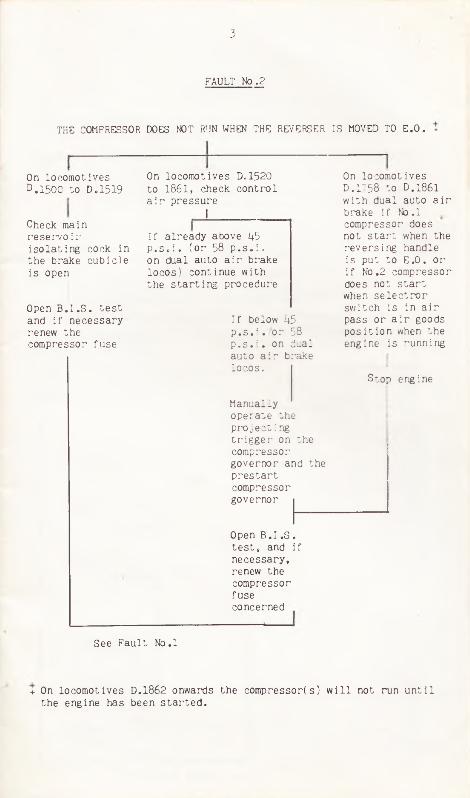
FAULT No .2
THE COMPRESSOR DOES NOT RUN WHEN THE REVERSER IS MOVED TO E.O. +
On locomotives D.1500 to D.1519
Check main reservoir isolating cock in the brake cubicle is open
Open B .I .S . test and i f necessary renew the compressor fuse
On locomotives D.1520 to 1861, check control a ir pressure
If already above kb p . s . i . (or 58 p . s . i . on dual auto a ir brake locos) continue with the starting procedure
If below 45p . s . i . or 58 p .s . i . on dual auto air brake locos.
Manually operate the projecting trigger on the compressor governor and the prestart compressor governor
Open B.I .S . te st , and if necessary, renew the compressor fuseconcerned
See Fault No.l
On locomotives D.1758 to D.1861 with dual auto a ir brake if No.l compressor does not start when the reversing handle is put to E.O. or i f No.2 compressor does not start when s e le c t o r switch is in a ir pass or a ir goods position when the engine is running
Stop engine
+ On locomotives D.1862 onwards the compressor(s) w ill not run until the engine has been started.

4
FAULT No.3
AIR PRESSURE DOES NOT BUILD UP WHEN THE COMPRESSOR IS RUNNING
Check a l l reservoir drain cocks, coupling cocks and connectionsfo r leaks
NOTE:- On locomotives D. l862 onwards the compressors w ill not run u ntil the engine has been started .
FAULT No. 4
ENGINE WILL NOT MOTOR
If indicator lights are out see Fault No. 1
On locomotives D.1500 - D.1519
Check main & control reservoir pressure
If no main reservoir I f main reservoir pressure registered pressure but no
control a ir pressure check control reservoir isolating
See Faults No.2 & 3 cock open
Check equipment isolating cocks are open
On locomotives D.1520 to D.1861
If no control a ir pressure
Check control a ir isolating cock open
Check equipment isolating cocks open
If compressor continues to run when pressure above 45 p . s . i . or 58 p . s . i . on dual auto a ir brake locos , operate projecting trigger on the prestart governor u ntil compressor s t o p s
On lo co motive D.1862 onwardsCheck the
control a ir pressure
Try an engine room start

4
If at or above minimum
Report f i l t e r s vented
Request assistance
Wait one minute with the Reverser at E.O.
Press and hold start button until 3 seconds a fter the red ligh t dims
If the engine does not motor within 15 seconds, or does not fire within 30 secondsrelease button
Requestassistance
Check engine room stop button pulled out
FAULT No .5
ENGINE WILL MOTOR, BUT WILL NOT FIRE
5
Press and release the stop button
Check overspeed trip Check fuel stop cock (near
tr ip le pump set) open
Check water pump control switch is at auto
Check o i l leve l In sump
Check pump set fu se .Renew if necessary.
Turn fuel o i l strainer several times
Vent micronic f i l t e r s
If below minimumRequest assistance
If engine overspeeds and stops
Reset i f necessary with lever provided

6
ENGINE FIRES, BUT STOPS WHEN THE START BUTTON IS RELEASED
FAULT No .6
Attempt another start ensuring that the start button is held in fo r 3 seconds a fter the red light dims
Check water pressure gauge. Pressure should be about 10 p . s . i . i f it is below 8 p . s . i . check level in tank, and, if necessary and possib le , top up.
Low cooling water pressure (or on locomotives D.1862 onwards low lev e l or pressure)
Fuel starvation
Act as for Fault 5 (check fuel stop cock e t c . )
Low lubricating o i l pressure
Check o i l level on sump dipstick
Act as for Fault No.5 Check o i l level in sump etc .
If pump is running
Turn switch to "D irect" and if pump s t i l l does not run test and, if necessary, renew the pump set fuse and turn switch back to "Normal"
Pump not running
Check water pump control switch at auto

7
VACUUM FAILS TO BUILD UP WHEN THE
FAULT No.7
Exhausters not running
Depress and release both brake valve handles - note the handle springs up
Check the exhauster isolating switches are in "Normal” position
On dual Auto Air Brake locos . Check brake se lector switch in vacuum position
Check exhauster fuses
ENGINE IS RUNNING
Exhausters Running
Check both vacuum brake handles or auto a ir brake handles are in correct positions
Check A.W.S. Isolating handle fu lly home and A.W.S. key is up in driving cab and down in non-driving cab.
Check hose couplings fo r leaks
Check D.S.D, not operated-- i f defective isolate it (driver must then be accompanied)

8
FAULT No.8
Alarm ligh t bright when con tro ller is away from "OFF"
Check exhauster switches not at "Test"
Check engine maintenance switch and slow speed switch at "Normal"
* Check train pipe vacuum normal. Fault 7.
Check a ir pressure in main and co n tro l r e s e r v o ir and tr a in p ip e . F a u lts 2 & 3 .
POWER CANNOT BE APPLIED
Alarm light bright when con tro ller is re-opened a fter coasting
Return the con tro ller to o f f - pause 15 seconds then re-open con tro ller
Alarm light does not brighten
Check A.W.S. key up in driving cab and down or removed in other cab
Check motor isolating switches correct
Operate triggers on V.C.G., C.C.G. and T.P.G. ( i f any). Check C.C.G. isolating cock is open
Power earth f a u l t . Get a s s is ta n c e i f a t d epot, o r see F au lt 9 .
* This applies to auto a ir braked locomotives only i f the brake se lector switch is in a vacuum p os it ion .
Check control a ir isolating cock to cubicle

FAULT N o . 9
Engine stopped ligh t bright. See Fault No. 12.
Alarm light bright when con tro ller is open
Check fau lt panel Check a ir and vacuum are normal
No fau lt indicated
Operate triggers on V.C.G. C.C.G. and T.P.G. ( if f i t t e d ) .If one o f these switches fa ils to remain closed it should be held In manually whilst the locomotive is worked forward to a point where another locomotive can be obtained.
Earth fault indicated. On D.1500 to D.1519 stop engine, open B .I .S . remove master key from the con tro ller remove link PE.IL. +
On D.1520 onwards turn E .I .S . to "Power Isolated" +
On D. 1520 onwards overload light bright
Return to driving position , press overload reset button and attempt another s ta r t .
I f , when attempting to restart, the wheelslip light brightens test fo r defective traction motors. See Fault 10
+ The earth link must be replaced or E .I .S . returned to "Normal" when leaving the locomotive and the matter
reported.
TRACTION POWER IS LOST
9

1 0
FAULT N o .10
FULL TRACTION POWER IS NOT AVAILABLE OR POWER IS REDUCED
Wheelslip lig h t brightens
Desk indicator ligh ts normal
Return con troller towards OFF
Check motor cut-out switches are at "A ll In"
Amber light dims. Press wheelslip button whilst notching up again and release it when main ammeter current begins to reduce
Amber light does not dim
Check for defective traction motors.Isolate motors one at a time or two at a time and apply sligh t power to check if amber light remains dim.Leave defective motor (o r pair) isolated . +
+ Defective motors can sometimes be detected by signs of heat or smoke. They are numbered from No.l end of the locom otive.
1 0 11
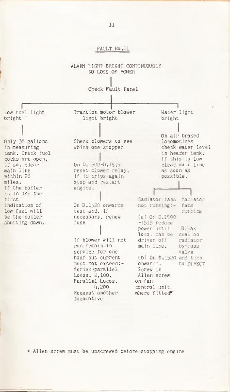
FAULT No.11
ALARM LIGHT BRIGHT CONTINUOUSLY NO LOSS OF POWER
Check Fault Panel
* Allen screw must be unscrewed before stopping engine
Low fuel light bright
Traction motor blower ligh t bright
Water light bright
Only 38 gallons in measuring tank. Check fuel cocks are open, if so, clear main line within 20 m iles.If the b o ile r is in use the f ir s tindication of low fuel w ill be the b o ile r shutting down.
Check blowers to see which one stopped
On D.1500-D .1519 reset blower relay . If It trips again stop and restart engine.
On D.1520 onwards test and, i f necessary, renew fuse
If blower w i l l not run remain in service fo r one hour but current must not exceed :- S er ies /p a ra lle l Locos. 2,100. Parallel Locos.
4,200Request another locomotive
Radiatorfansrunning
Radiator fans not running: -
On a ir braked locomotives check water level in header tank.If th is is low clear main line as soon as possib le .
(a) On D.1500 -1519 reduce power until lo c o . can be driven o f f main lin e .
(b ) On D.1520 onwards.Screw in Allen screw
on fan control unit where fitted *
Break seal on radiator by-pass valve and turn to DIRECT

12
FAULT No.12
ENGINE STOPS IN SERVICE
Desk Indicator lights out
Reset control c ircu it breaker.I f it trips again on D1500/1519 remove A .E .I.L . or on D.1520 onwards turn E .I .S. to *A uxiliaries Isolated" and reset breaker
Alarm ligh t bright Alarm light dim
Check fault panel
Water ligh t bright
O il pressure ligh t bright
Check pump set
Check level in sump
Pump set not running
Pumpsetrunning
Turn water pump switch to "D irect” and if pump does not run check fuse NOTE. If pump is run with switch at "D irect" the switch must be returned to "Auto" when the engine is stopped
Checkwaterpressure.If below 8 p . s . i . check lev e l in radiator tanks.If low getassistance.
Engine ligh t dims and engine f ir e s . Check o i l pressure above 20 p .s . i If below th is pressure proceed but request
another locom otive. If trouble occurs again clear main l in e .
Engine light does not dim
Requestassistance
Check fuel cock near pump set is wide open
Below Min.Requestassistance
I f not below Min.
Let pump set run fo r one minute then try to start
Check overspeed tr ip and reset if necessary. I f it trips again restart engine, clear main line on low power and stop engine
If low fuel warning has not been received turn handle on fuel strainer and vent f i l ters

12 13
If vo lts below 107, do not stop engine. Request assistance at convenient point
FAULT No.13
NO BATTERY CHARGE
i
Check battery voltmeter
If vo lts above 107, proceed

FAULT No. 14
VACUUM BRAKED LOCOMOTIVE FAILS IN SERVICE AND ASSISTANCE IS REQUIRED
Assistance by vacuum braked locomotive
Assistance by a ir braked locomotive
Couple shackle, vacuum train pipes and main reservoir equalising pipe (one side is su ffic ie n t)
On assisting On disabledlocomotive locomotive
Check braked/unbraked switch
Isolate D.S .D. and open B .I .S .
Couple shackle, vacuum train pipes and brake feed pipe of assisting lo co , to main reservoir equalising pipe o f
disabled lo co .
On assisting locomotive
Check brake se lector switch is at Vacuum Braked or Unbraked as required
Proceed to destination or dispose of disabled locomotive at convenient depot.Under these conditions the brakes on the disabled locomotive w ill only operate at unbraked timings. Due caution is essen tia l.
Remove master key, pu ll down A.W.S. key. Place vacuum and a ir brake handles to release

15
FAULT No.15
AIR BRAKED LOCOMOTIVE FAILS IN SERVICE AND ASSISTANCE IS REQUIRED
On disabled locomotive(a) Remove master key and pull down A.W.S. key(b) Check auto brake valves and in "Neutral” and straight
a ir brake valves in "Off"(c ) Isolate D.S.D. and open B .I .S .
Check brake selector switch is in correct position for type of train
If on a ir braked train release train brakes by hand
If on vacuum braked train a ll brakes w ill be operative
it ion orProceed to destination or dispose of disabled locomotive at convenient depot.Due allowance must be made for slow application of brakes on disabled locomotive.
Assistance by an a ir braked locomotive
Assistance by a vacuum braked locomotive
On a ir braked train
On vacuum braked train
Coupleshackle, a ir train pipes and brake- feed pipes
Couple, shackle, brake-feed pipes and vacuum pipes
Press the a ir / vacuum relay valve release button fo r a fewseconds
All brakes w ill be operative
Close air/vacuum relay valve isolating cock on defective locomotive and press air/vacuum relay valve release button*Place Braked Unbraked switch in appropriate position on leading l o c o .
Couple shackle, vacuum pipes and main reservoir equalising pipe to brake feed pipe
Brakes w ill only be operated on the two locomotives. Proceed with caution in accordance with instructions received.
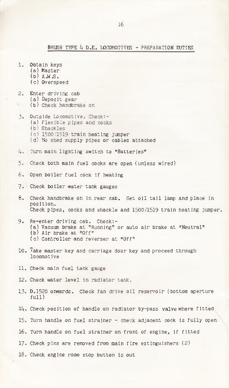
BRUSH TYPE 4 D.E. LOCOMOTIVES - PREPARATION DUTIES
1. Obtain keys(a) Master(b) A.W.S.(c ) Overspeed
2. Enter driving cab(a ) Deposit gear(b) Check handbrake on
3. Outside Locomotive. Check:-(a) F lexible pipes and cocks(b) Shackles(c ) 1500/1519 train heating jumper(d) No shed supply pipes or cables attached
4. Turn main lighting switch to "B atteries”
5. Check both main fu el cocks are open (unless wired)
6. Open b o iler fu e l cock i f heating
7 . Check b o ile r water tank gauges
8. Check handbrake on in rear cab. Get o i l t a i l lamp and place in p osition .Check pipes, cocks and shackle and 1500/1519 train heating jumper.
9 . Re-enter driving cab. Check:-(a ) Vacuum brake at "Running” or auto a ir brake at "Neutral"(b) Air brake at "O ff"(c ) C ontroller and reverser at "O ff”
10. Take master key and carriage door key and proceed through locomotive
11. Check main fuel tank gauge
12. Check water level in radiator tank.
13. D.1520 onwards. Check fan drive o i l reservoir (bottom aperture fu l l )
14. Check position of handle on radiator by-pass valve where f it te d
15. Turn handle on fuel strainer - check adjacent cock is fu lly open
16. Turn handle on fu el stra iner on front of engine, i f f it te d
17. Check pins are removed from main f ir e extinguishers (2)
18. Check engine room stop button is out
16

17
19. Side door secure
20. At control cubicle - check:-(a) C ircuit breakers
( i ) D.1500 - D.1519 Up - red spot showing ( i i ) D. 1520 onwards Down
( b ) Fuses complete(c ) Motor i s olating switches at "A ll in" (3)(d) Exhauster switches "Normal” (2 )(e ) Water pump switch "Auto!l( f ) ( i ) Braked/Unbraked switch, where f i t te d , at "Braked"
( i i ) Air/Vacuum switch, where f i t te d , at Air/Pass(g) D. 1500 - D.1519 train heat switch "O ff”(h) D.1520 onwards - earth isolating switch and engine
maintenance switch
21. Close B.I .S .
22. Remove pin from No.3 extinguisher
23. Check main fue l tank gauge - NOTE if driving from No.2 cab items11 to 23 are performed in the reverse order
24 . In rear cab(a) Check desk indicator lights - red bright, amber and blue dim
On D.1500 - 1519 red heating light dim(b) Insert master key and move reverser to E.O.
(water pump set and except on lo cos . D.1862 onwards compressor should start)
(c ) On D.1500 - 1519, when 45 p . s . i . a ir in main reservoir, or or D.1520 onwards - a fter one minute press start button and hold u n til three seconds a fter red light dims. Start button rust not be held fo r more than 15 seconds if engine does not rotor and not more than 30 seconds if the engine motors but does not fir e
(d) Check vacuum brake at "Running" or Auto a ir brake at "Neutral"(e ) Check straight a ir brake handle at "O ff"( f ) Press f ir e alarm test button (note b e ll r in gs)(g ) Check fir e extinguishers(h) Check detonators and red flags( i ) Set route indicator and check lights( j ) Check A.W.S. handle is Up and change end handle down if
painted blue(k) Check no vacuum in chamber, operating release handle if
necessary( l ) ( i ) On dual auto a ir braked locomotives move auto brake
handle to "Running" an d w hen 70 p .s .i. is available in train pipe test brake.When test is complete make emergency application and when a ir train pipe is at zero lock handle to "Neutral"
( i i ) On a ir vacuum locomotives when 21 Ins. vacuum in train pipe fu lly apply vacuum brake and check brake cylinder pressures.

18
(m) Move reverser to "O ff" and turn and remove master key.On a ir vacuum locomotives place vacuum brake handle to "Running”
(n) Release hand-brake. Switch o ff lights and close doors e tc .
25. Proceed to driving cab checking( a) Cubical ligh ts normal( b ) Battery ammeter and control a ir pressure gauges( c ) Change Air/Vacuum switch to Vacuum/Braked, (where f i t te d )(d ) Check other side door secure(e ) Check pipework for leaks
26. In driving cab(a ) Insert and turn master key and put reverser handle to E.O.(b) Press f ir e alarm test button (note b e ll rings)(c ) Move A.W.S. key fu lly up (press button to cancel horn)( d ) Check hand f ir e extinguishers, detonators, red flags and
head-lamp( e ) Set route indicator and test lights( f ) Check main reservoir a ir pressure is normal(g ) On dual a ir braked locomotives more auto a ir brake handle
to "Running"(h) Test auto and straight a ir brakes in a l l positions( i ) Test drivers ’ safety device( j ) With D.S.D. applied release handbrake(k) Test two tone horn and proceed.
CHANGING ENDS
1. (a) On dual auto a ir braked locomotives( i ) Place auto a ir brake handle to "Emergency"
( i i ) Check a ir train pipe pressure at zero( i i i ) Lock auto a ir brake handle in "Neutral”
(b ) On auto vacuum braked locomotives move vacuum brake handle to "Emergency”
2. Move reversing handle to "O ff” and turn and remove master key
3. On auto vacuum locomotives move vacuum brake handle to "Running”
1+. Pull down A.W.S, key and remove i f painted green (blue handles and not removable)
5. Switch o f f lights e tc . and close doors and windows
6. Check brake cylinder pressures are holding and proceed to other cab without delay.Check battery ammeter and a ir vacuum switch in position fo r next movement. Check fau lt panel.

7 . In other cab(a) Make holding application o f a ir brake(b) Insert and turn master key and move reverser handle to E.O.(c ) Move A.W.S, key up(d) On dual auto a ir braked locomotives move auto a ir brake
handle to "Running" and if changing from vacuum to a ir destroy chamber vacuum by operating release valve.
(e ) Set route indicator( f ) Test drivers' safety device(g) Test two tone horn before proceeding
STABLING
1. Stop and hold locomotive with a ir brake
2. Apply handbrake
3. Move A.W.S. key down and remove handle if green
4. Move reverser handle to "O ff" , stop engine and remove master key
5 . Move straight a ir brake handle to o f f
6 . ( i ) I f auto vacuum braked locomotive move vacuum brake handle to"Running" and on Nos. D.1520 onwards destroy chamber side vacuum by operating release valve
( i i ) If dual auto a ir brake move handle to "Emergency" and when a ir train pipe pressure is at zero lock handle in "Neutral"
7 . Switch o f f lights e tc . and close doors and windows
8. Proceed to other cab(a) Open B .I .S .(b) Check levels in radiator tank and fan drive o i l reservoir and
report i f low( c) Operate a ir release valve on brake cubicle ( I f fitted )
9 . In rear cab(a ) Apply handbrake(b) Destroy chamber vacuum by operating release valve(c ) Return t a i l lamp to cab(d) Switch o f f lights e tc . and close windows and doors(e) Record known defects( f ) Turn main lights switch to "Shore Supply"(g ) Return keys and draw attention to urgent defects
19