For A, B and C Series CarveWright and CompuCarve...
53
LHR Technologies, Inc. CarveWright™ Troubleshooting Guide (Rev 1.07) 05/10/11 1 Troubleshooting Guide For A, B and C Series CarveWright and CompuCarve Machines Please note that this guide has been generated to help users identify machine issues and diagnose certain common causes. It is not a repair guide and should not be treated as such. Any repair to your CompuCarve or CarveWright machine must be at the direction of a trained CarveWright service technician in order to satisfy all warranty conditions. Also note that the issues listed below are compiled from all machine configurations from the beginning of production and many of them will not apply to your machine configuration.
Transcript of For A, B and C Series CarveWright and CompuCarve...
LHR Technologies, Inc. CarveWright™ Troubleshooting Guide (Rev 1.07) 05/10/11 1
Troubleshooting Guide For A, B and C Series CarveWright and CompuCarve Machines
Please note that this guide has been generated to help users identify machine issues and diagnose certain common causes. It is not a repair guide and should not be treated as such. Any repair to your CompuCarve or CarveWright machine must be at the direction of a trained CarveWright service technician in order to satisfy all warranty conditions. Also note that the issues listed below are compiled from all machine configurations from the beginning of production and many of them will not apply to your machine configuration.

LHR Technologies, Inc. CarveWright™ Troubleshooting Guide (Rev 1.07) 05/10/11 2
Troubleshooting Guide
Board Too Thick to Cut Message ................................................................................................... 5
Check Cut Motor Message.............................................................................................................. 6
Check Tracking Roller Message ..................................................................................................... 7
Edge Detection Failure Message .................................................................................................... 9
Error Loading Size: 28 Message ................................................................................................... 11
Please Clear Board Sensor Message ............................................................................................. 12
Please Close Cover Message ........................................................................................................ 14
Please Load Bit Message .............................................................................................................. 15
Please Load Board Message ......................................................................................................... 16
Please Set Sliding Plate Message .................................................................................................. 17
Possible Board Problem Message ................................................................................................. 18
Possible Board Removal Message ................................................................................................ 19
Power Fluctuation Message .......................................................................................................... 20
SRAM Message ............................................................................................................................ 21
Stuck Compression Roller Message ............................................................................................. 22
System Error (81). Please Contact CarveWright Message. ......................................................... 23
Bit Not Touching the Bit Plate...................................................................................................... 24
Carving Edge Shifts in the Y Direction ........................................................................................ 25
Carving Gets Shallower Going Side to Side ................................................................................. 26
Carving Increases in Depth ........................................................................................................... 27
Carving of an Imported Image is Very Rough .............................................................................. 28
Clicking Sound Heard During Homing or Carving ...................................................................... 29
Cut Motor Changes Speed in the Middle of the Project. .............................................................. 30
Cut Motor Not Spinning ............................................................................................................... 31

LHR Technologies, Inc. CarveWright™ Troubleshooting Guide (Rev 1.07) 05/10/11 3
Flexshaft Core Breaking at the End .............................................................................................. 32
Flexshaft is Overheating or Melted ............................................................................................... 33
Head Will not Lower .................................................................................................................... 34
Head Will not Raise Up ................................................................................................................ 35
Inconsistent Board Measurements or Tracking Issues .................................................................. 36
LCD is Blank ................................................................................................................................ 38
LCD Shows Black Squares ........................................................................................................... 39
LCD Shows Random Characters .................................................................................................. 40
Machine Reboots at Random Times ............................................................................................. 41
No Power to the Machine ............................................................................................................. 42
Random Errors Caused by Board Being too Thin ........................................................................ 43
Random X, Y, or Z-Axis Stall Errors ........................................................................................... 44
Sandpaper Belt is Torn .................................................................................................................. 45
Sandpaper Belt is Rolling Up ....................................................................................................... 46
Scan Area Message Appears Instead of the Main Menu .............................................................. 47
X Gears Broken or Striped ............................................................................................................ 48
Z-Truck Overheating .................................................................................................................... 49
Consolidated Error Codes ............................................................................................................. 50
E02 - Exception stack fault ...................................................................................................................................... 50
E03 - Board edge detection failure .......................................................................................................................... 50
E04 - X axis stall ..................................................................................................................................................... 50
E05 - Y axis stall (Normal) ...................................................................................................................................... 51
E06 - Z axis stall (Normal) ...................................................................................................................................... 51
E09 - Homing fault (Low) ....................................................................................................................................... 51
E10 - No Bit Detected (Low) ................................................................................................................................... 52
E14 - Cutter arm fault (Low) ................................................................................................................................... 52

LHR Technologies, Inc. CarveWright™ Troubleshooting Guide (Rev 1.07) 05/10/11 4
E16 - Bit Selection Error (Low) .............................................................................................................................. 52
E17 - Board find range (Low) ................................................................................................................................. 52
E32 - Tracking Sensor Fault (Low) ......................................................................................................................... 52
E33 - Front Roller Fault (Normal) ........................................................................................................................... 52
E34 - Back Roller Fault (Normal) ........................................................................................................................... 52
E37 - Cut Motor Motor Sensor Fault (Low) ............................................................................................................ 52
E44 - User calibration failure (Low) ........................................................................................................................ 52
E45 - Settings value out of range (Never) ............................................................................................................... 53
E46 - Attempting to call pure virtual method (Never) ............................................................................................. 53
E47 - Probe Detected (Never) .................................................................................................................................. 53
E48 - Waiting on motion while servoing disabled (Low) ........................................................................................ 53
E49 - Tracking roller failed (Low) .......................................................................................................................... 53
LHR Technologies, Inc. CarveWright™ Troubleshooting Guide (Rev 1.07) 05/10/11 5
Board Too Thick to Cut Message Description of Issue The “Board Too Thick to Cut” message appears on the LCD screen when the machine measures the inserted board thickness and determines that it is thicker than the cutting bit can cut all the way through. This message will only appear if there is a cutting operation in the project. Possible Causes The causes can be: a sliding plate that is not slid all the way over against the board, the wrong bit his inserted into the machine, a case where the user is using a jig on a project that has a cut-out in it and the height of the jig does not allow the bit to touch the board sensor during homing, or a damaged board sensor. Troubleshooting Steps
1. Verify that the board is NOT over 1” thick. 2. Check that the sliding plate is slid over against the edge of the board. 3. Verify that the correct bit is inserted and correctly assembled. 4. Check hole in the board sensor. Check for a hole on the board tracking sensor - Look on
the plastic bar of the board tracking sensor for hole. If there is a hole, place a dime on top of that and run the machine. Machine should run normally after that. You also obtain a clip (Board Position Encoder touch plate - P1323) to cover the hole.
5. Check Tracking Roller" error message. This error is shown because of out of limit numbers when measuring the length of the board.
6. Run a project and watch where the error occurs and what the machine is attempting to do. 7. Consult CarveWright.

LHR Technologies, Inc. CarveWright™ Troubleshooting Guide (Rev 1.07) 05/10/11 6
Check Cut Motor Message Description of Issue The machine can report a Check Cut Motor message when the sensors are not reading the expected cut motor RPM. This cut motor message can be disregarded if the user desires. The motor will run without the sensor feedback but may run fast. Possible Causes Causes include: a cut motor that is not spinning (various reasons), a bad cut motor sensor, a faulty cut motor sensor magnet, or a faulty X termination board. Troubleshooting Steps
1. Check to see that the cut motor is spinning when it should be spinning. If the cut motor is not spinning see the section titled “Cut Motor Not Spinning”.
2. Check to see that the cut motor sensor is recording the shaft as it spins. To check the status of the cut motor sensor, go to the CarveWright Main Menu->Configuration->Sensor Check menu. Use the arrow keys to find the item titled “Cut Sensor” on the bottom line of the display. Spin the spindle as fast as possible by hand and see if the count on the display changes. If the count is not changing the magnet and/or the cut sensor is bad.
3. If the cut motor RPMs are fluctuating during the project (readily heard), check the leads on the large brown capacitor on the X termination board for breakage. Replace the X termination board if necessary.
4. If none of the above steps solves the issue consult CarveWright.
LHR Technologies, Inc. CarveWright™ Troubleshooting Guide (Rev 1.07) 05/10/11 7
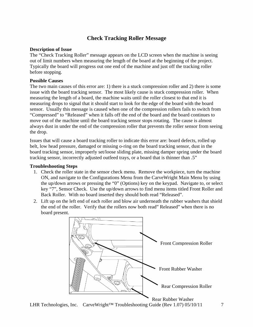
Check Tracking Roller Message
Description of Issue The “Check Tracking Roller” message appears on the LCD screen when the machine is seeing out of limit numbers when measuring the length of the board at the beginning of the project. Typically the board will progress out one end of the machine and just off the tracking roller before stopping.
Possible Causes The two main causes of this error are: 1) there is a stuck compression roller and 2) there is some issue with the board tracking sensor. The most likely cause is stuck compression roller. When measuring the length of a board, the machine waits until the roller closest to that end it is measuring drops to signal that it should start to look for the edge of the board with the board sensor. Usually this message is caused when one of the compression rollers fails to switch from “Compressed” to “Released” when it falls off the end of the board and the board continues to move out of the machine until the board tracking sensor stops rotating. The cause is almost always dust in under the end of the compression roller that prevents the roller sensor from seeing the drop.
Issues that will cause a board tracking roller to indicate this error are: board defects, rolled up belt, low head pressure, damaged or missing o-ring on the board tracking sensor, dust in the board tracking sensor, improperly set/loose sliding plate, missing damper spring under the board tracking sensor, incorrectly adjusted outfeed trays, or a board that is thinner than .5”
Troubleshooting Steps 1. Check the roller state in the sensor check menu. Remove the workpiece, turn the machine
ON, and navigate to the Configurations Menu from the CarveWright Main Menu by using the up/down arrows or pressing the “0” (Options) key on the keypad. Navigate to, or select key “7”, Sensor Check. Use the up/down arrows to find menu items titled Front Roller and Back Roller. With no board inserted they should both read “Released”.
2. Lift up on the left end of each roller and blow air underneath the rubber washers that shield the end of the roller. Verify that the rollers now both read” Released” when there is no board present.
Rear Compression Roller
Front Compression Roller
Rear Rubber Washer
Front Rubber Washer

LHR Technologies, Inc. CarveWright™ Troubleshooting Guide (Rev 1.07) 05/10/11 8
3. Check the board for defects (existing carvings, warping, holes, rounded edges, etc.) and make sure it is inserted correctly into the machine. For a detailed discussion on the board requirements please see the “Inserting a Board” section in the CarveWright Owner’s manual.
4. Verify that the board is thicker than .5”. 5. Check that the sliding plate is tight and up against the board. A board that is not captured
by the sliding plate will allow the board to walk slightly from side to side. This small amount of walking can lead to a wide variance in measured lengths.
6. Check to see if the squaring plate (where the tracking sensor is attached) is loose. This is a rare issue but it can happen. If the square plate is loose, it will not measure the board right and could give the Edge Detection error, possible board removal, or give a wrong measurement for the board. Re-tighten the 2 screws that hold the squaring plate.
7. Verify that the board sensor rotates freely. 8. O-ring on the board tracking sensor is in place and not damaged. 9. Verify that the head pressure is within correct limits. 10. Verify that neither of the belts are damaged or rolled up. 11. Verify that the damper spring is still under the board tracking sensor. 12. Check to see that the outfeed rollers are not adjusted too high. If they are high they can lift
the board off of the board tracking roller during operation and cause it to lose track of the position.
13. Check for dust in the board tracking sensor. 14. If none of the above steps solves the issue consult CarveWright.

LHR Technologies, Inc. CarveWright™ Troubleshooting Guide (Rev 1.07) 05/10/11 9
Edge Detection Failure Message Description of Issue The edge detect failure occurs when the board sensor gets bad data when looking for a board edge during the initial measuring and homing part of the project. Possible Causes Causes include: a low board sensor reading, a very dark color workpiece, sawdust on the sliding plate, a hole in the board, or board tracking issue that confuses the board sensor when looking for an edge. These tracking issues can include: board defects, rolled up belts, low head pressure, dust in the board tracking sensor, improperly set/loose sliding plate, missing damper spring under the board tracking sensor, or incorrectly adjusted outfeed trays. Troubleshooting Steps
1. Determine if the error is occurring when measuring the edge in the Y direction (left to right across the machine) or in the X direction (in and out of the machine). If it occurs when measuring in the Y direction, proceed with Step 2. If it occurs when measuring the X direction, skip to Step 8.
2. Check the board sensor reading when the Y truck is pushed all the way over to the left side of the machine (off the board). It should read less than 10. Then move the truck over a light colored board and verify that the reading is greater than 100. If either of these values is not met please refer to the “Please Clear Board Sensor” document.
3. Verify that the color of the workpiece is not too dark by making sure that the board sensor is reading at least 100 while over a light colored workpiece.
4. Check the board for defects (existing carvings, warping, holes, rounded edges, etc.) and make sure it is inserted correctly into the machine. For a detailed discussion on the board requirements please see the “Inserting a Board” section in the CarveWright Owner’s manual.
5. Check that the sliding plate is tight and up against the right side of the board and clear of sawdust.
6. Next check and see if there is dust in the Y encoder that is causing it to lose track of position. Check the Y encoder readings in the sensor check menu. Turn the machine ON and navigate to the Configurations Menu from the CarveWright Main Menu by using the up/down arrows or pressing the “0” (Options) key on the keypad. Navigate to, or select key “7”, Sensor Check. Use the up/down arrows to find menu items titled Y Position. Record the encoder readings for the far left and right positions as you move the Y truck. The total Y travel should read between 15.5” and 16”. Move it back and forth several times checking to see that the values at each side do not change. Replace the motor pack if these readings do not match up.
7. If none of the above steps solves the Y edge detection failure, consult CarveWright. 8. Check to see if the squaring plate (where the tracking sensor is attached) is loose. This is a
rare issue but it can happen. If the square plate is loose, it will not measure the board right and could give the Edge Detection error, possible board removal, or give a wrong measurement for the board. Re-tighten the 2 screws that hold the squaring plate.

LHR Technologies, Inc. CarveWright™ Troubleshooting Guide (Rev 1.07) 05/10/11 10
9. Verify that the head pressure is within correct limits. 10. Verify that neither of the belts are damaged or rolled up. 11. Verify that the damper spring is still under the board tracking sensor. 12. Check to see that the outfeed rollers are not adjusted too high. If they are high they can lift
the board off of the board tracking roller during operation and cause it to lose track of the position.
13. Check for dust in the board tracking sensor. 14. If none of the above steps solves the issue consult CarveWright.

LHR Technologies, Inc. CarveWright™ Troubleshooting Guide (Rev 1.07) 05/10/11 11
Error Loading Size: 28 Message Description of Issue The machine will tend to show this error message during the beginning process or starting a carving when it cannot access the memory card data. Possible Causes The machine displays this error message when the project on the memory card has been corrupted. It improperly loads the incorrect project size, resulting in the error message. Troubleshooting Steps
1. Take the card back to the computer and reformat the memory card. Overwrite the firmware on the card. This is very important even if the version is the same.
2. Load the project again and try running the project. 3. If the problem persists, email the project file to CarveWright support for analysis.

LHR Technologies, Inc. CarveWright™ Troubleshooting Guide (Rev 1.07) 05/10/11 12
Please Clear Board Sensor Message Description of Issue This error appears when the sensor used to find the edges of the workpiece is not seeing reading within its operational limits. The sensor system consists of an infrared LED and an infrared detector. The board sensor works by reflecting infrared light off of the board and reading the intensity of the reflection. When the board is underneath the sensor, the reflected intensity is high and when the sensor is off the edge of the board, the intensity is low. The LED and detector are mounted behind a clear window in a plastic case at the bottom of the horizontal moving Y-Truck. Possible Causes There are several reasons why the machine will prompt the user to “Clear Board Sensor” including:
1. There is dust obscuring the sensor lens. 2. There is dust piled in the machine to the right of the board that looks like a continuation of
the board to the sensor. 3. There are existing features on the workpiece, like holes or other carved features, which
prevent the sensor from tracking the top surface. 4. The material is too transparent or reflective. 5. The board is positioned incorrectly in the machine; usually the board is installed on top of
the squaring plate instead of up against it. It will also give this error if the board is placed in the middle of the machine and not slid up against the strongback.
6. The environmental temperature is below 40 degrees Fahrenheit. Troubleshooting Steps The following steps only touch on the most likely causes of this issue. For an in-depth troubleshooting procedure please consult the detailed trouble shooting document titled “Please Clear Board Sensor”
1. Clean the Board Sensor. The most common reason for this issue to occur is that the sensor is obscured by dust. To clean, simply blow low-pressure compressed air (<80 psi) onto the sensor window or wipe with a clean cloth. It is recommended that this sensor be cleaned after every project. If using pressurized canned air make sure to keep the can vertical. If the can is tipped upside down it will eject a stream of freezing liquid instead of air. This will usually damage the sensor.
2. Verify that the temperature is above 40oF. 3. Verify that the board is pushed up against the squaring plate and not riding on top of it. 4. Check to see that there is no dust piled on the squaring plate that may trick the sensor. 5. Verify that there are no existing features on the workpiece, like holes or other carved
features, which trick the sensor into thinking that it has found the edge and preventing it from seeing the entire top surface of the board. Use masking tape to hide these features from the sensor.
6. Verify that the material is not too transparent or reflective. Since the sensor works by using reflected light to determine the board edge, any material that is very light in color or

LHR Technologies, Inc. CarveWright™ Troubleshooting Guide (Rev 1.07) 05/10/11 13
very dark in color cause it to get a reading that is out of its normal limits. This can be fixed by placing a piece of masking tape on the surface of the workpiece along the line that the sensor traces while measuring. This generally requires placing tape across the width and length of the workpiece.
7. If the board sensor error cannot be resolved by doing the above checks you will need to check the sensor readings directly to see if it is working properly. To check the status of the board edge sensor, go to the CarveWright Main Menu->Configuration->Sensor Check menu. Use the arrow keys to find the item titled “Board Sensor” on the bottom line of the display. Do the following checks:
a. Load a pine or similar colored board, lower the head, and check the reading displayed on the LCD when the sensor is over the board. Anything reading over 90 is acceptable. Anything under 90 requires a new sensor.
b. Check the reading displayed on the LCD when the sensor is not over a board by moving the cutting head all the way to the left. The correct reading should be less than 10 and ideally 0.
c. Raise the head, so that a small board can be easily place underneath the Board Sensor. Move it up and down so as to cause the Board Sensor reading to go greater than 50. Quickly remove it from under the sensor. The reading should drop immediately to less than 10 and ideally 0. If it does not drop immediately the sensor is faulty and needs to be replaced.
8. If none of the above steps solves the issue consult CarveWright and the detailed trouble shooting document titled “Please Clear Board Sensor”.
LHR Technologies, Inc. CarveWright™ Troubleshooting Guide (Rev 1.07) 05/10/11 14
Please Close Cover Message Description of Issue The “Please Close Cover” message appears once the project begins even though the cover is closed. The machine has two switches that check to see that the cover is down before cutting. The left one reports the cover state to the electronics and the left one connects the power circuit to the cut motor which allows it to run when the cover is down. If the left one is not showing “Closed” then the machine will show this message. Possible Causes Causes include: a faulty cover switch (or full of dust), a loose cover or switch, a bent cover that does not allow the cover to fully actuate the switch, or a disconnected cover cable on the head termination board (seen especially right after servicing where the cover was removed). Troubleshooting Steps
1. Check the state of the cover switch in the sensor check menu. Turn the machine ON and navigate to the Configurations Menu from the CarveWright Main Menu by using the up/down arrows or pressing the “0” (Options) key on the keypad. Navigate to, or select key “7”, Sensor Check. Use the up/down arrows to find menu items titled Cover Switch. With the cover up it should say “Open” and with the cover closed it should say “Closed”. Open and close the cover and see if the switch changes state for “Open” to “Closed”.
2. Check that the left cover hinge cover is not loose and that the switch is not loose. If either is loose it can affect the actuation of the switch button by the finger on the clear cover.
3. Verify that the connectors to the switch are in place and tight. 4. Take a small implement and manually depress the switch button by hand. If you can get
the LCD to switch to “Closed” then there is something wrong with the cover that is preventing it from depressing the switch far enough. Resolve this cover issue.
5. Also listen for a clicking sound as you depress the switch by hand. If the connector is seated and the clicking can be heard without the cover showing “Closed” then most likely the switch has dust in it or is bad. Blow out the switch and test again.
6. If the error occurs during carving then check the cover engagement with the switch. It is possible that the vibration lifts the cover enough to release the switch momentarily. In this case it usually happens with regularity. Adjust the cover so that the switch engagement is positive
7. If the machine has recently been serviced and the cover was removed it is very possible that the switch cable was not plugged in correctly. Verify that the cover cable is correctly plugged into the head termination board. Unplug and re-plug if the seating is unsure.
8. If none of the above steps solves the issue consult CarveWright.

LHR Technologies, Inc. CarveWright™ Troubleshooting Guide (Rev 1.07) 05/10/11 15
Please Load Bit Message Description of Issue The “Please Load Bit Error” message occurs during homing when the machine is unable to verify the position of the bit tip. The machine uses surfaces on the board tracking sensor (in the cutout of the strongback at the far left of the bit travel) and the swinging bit touch plate (at the far right of travel) to locate the position of the bit tip. Failure to touch these surfaces results in this error. Possible Causes Causes include: no bit loaded into the machine, outdated firmware, incorrectly assembled bit, a malfunctioning bit plate, or a damaged board sensor. Troubleshooting Steps
1. Verify that the correct bit is inserted, correctly assembled, and not loose. 2. Check that the Y/Z trucks are not loose. 3. Verify that the card has the latest firmware version. 4. Check for damage (usually a hole) on the board tracking sensor body. The damage will be
on the plastic bar of the board tracking sensor where the bit touches during homing at the far left of its travel. If there is a hole, temporarily place a dime in the triangular recess of the board sensor over the hole and run the machine. If this fixes the issue, add the Board Position Encoder Touch Plate (P1323) instead of the dime.
5. Run a project and watch if the bit plate is swinging out far enough for the bit to touch when it moves down. The bit should touch on the flat surface of the plate and not on the edge. If the plate is not swinging out far enough clean and lubricate the bit plate pivot post and spring. Clean the plate mechanism with compressed air and spray WD40 on the spring. Crank the head all the way up to the top and spry upward at the pivot shaft. Actuate the bit plate several times to let the WD40 penetrate the mechanism.
6. Re-tension the Y belt. A loose belt can decrease the force that the Y-truck uses to swing the bit plate out.
7. If the bit is touching the swinging bit plate on the flat surface and still getting the error, rotate the bit plate all the way and push down, slightly bending the plate down. This will slightly bend the plate and increase the depth measurement.
8. If the bit is still not touching the bit plate then proceed to the "Bit Not Touching the Bit Plate" section.

LHR Technologies, Inc. CarveWright™ Troubleshooting Guide (Rev 1.07) 05/10/11 16
Please Load Board Message Description of Issue The “Please Load Board” message comes up when the machine begins to measure the board and senses that there is not a board in the machine. It checks that both compression roller sensors are reading compressed to verify that a board is loaded into the machine. Possible Causes Causes include: no board loaded into the machine, a board loaded only under one roller, the head is not cranked down, a warped board, a board with features carved all the way across the width of the board, a board that is too thin, low head compression, or a bad compression roller sensor. Troubleshooting Steps
1. Check that a workpiece is in the machine (and under both rollers) and that the head is cranked down properly.
2. Verify that the board is not thinner than 1/2". 3. Check for major features on the board that would cause one roller to compress and the
other to be released. The workpiece needs to be flat, smooth and without warps or significant thickness change.
4. Verify that the head pressure is within correct limits. This is especially important when carving wide material because the rollers do not compress as much the wider it gets.
5. Check for a stuck or defective compression roller. Please review the section titled “Stuck Compression Roller” in this troubleshooting guide.
6. If none of the above steps solves the issue consult CarveWright.

LHR Technologies, Inc. CarveWright™ Troubleshooting Guide (Rev 1.07) 05/10/11 17
Please Set Sliding Plate Message Description of Issue The “Please Set Sliding Plate” message comes up when the machine is unable to locate the sliding plate with the tip of the bit, usually when measuring the bit before doing a cut-out operation. The tip of the bit goes below the bottom plane of the board during the cut-out operation and uses the sliding plate as a depth reference so as not to damage the machine. Possible Causes The causes can be: a sliding plate that is not slid all the way over against the board, a case where the user has put the wrong bit into the machine and it is too short to reach the sliding plate, or a case where the user is using a jig on a project that has a cut-out in it and the height of the jig does not allow the bit to touch the sliding plate. Troubleshooting Steps
1. Check to see that the sliding plate is set up against the board. 2. Check and double check that the bit that is inserted is in fact the bit that the machine is
calling for. As noted usually this happens when trying to do a cutout. 3. Check to see if the user is using a jig. Some jigs can be too high for the cutout function to
work properly. 4. If none of the above resolve the issue, set up a project and watch exactly the sequence of
events and where the error occurs. Then bring this information to a CarveWright for consultation.

LHR Technologies, Inc. CarveWright™ Troubleshooting Guide (Rev 1.07) 05/10/11 18
Possible Board Problem Message Description of Issue The Possible Board Problem message occurs when the board tracking sensor is unable to closely track the board with respect to the commanded motion of the drive motors. Possible Causes Cause can be: board defects, rolled up belt, low head pressure, damaged or missing o-ring on the board tracking sensor, dust in the board tracking sensor, improperly set/loose sliding plate, missing damper spring under the board tracking sensor, incorrectly adjusted outfeed trays, a board that is thinner than .5”, or excessive backlash in the X-drive gears. Troubleshooting Steps
1. Check the board for defects (existing carvings, warping, holes, rounded edges, etc.) and make sure it is inserted correctly into the machine. For a detailed discussion on the board requirements please see the “Inserting a Board” section in the CarveWright Owner’s manual.
2. Verify that the board is thicker than .5”. 3. Check that the sliding plate is tight and up against the board. A board that is not captured
by the sliding plate will allow the board to walk slightly from side to side. This small amount of walking can lead to a wide variance in measured lengths.
4. Check to see if the squaring plate (where the tracking sensor is attached) is loose. This is a rare issue but it can happen. If the square plate is loose, it will not measure the board right and could give the Edge Detection error, possible board removal, or give a wrong measurement for the board. Re-tighten the 2 screws that hold the squaring plate.
5. Verify that the board sensor rotates freely. 6. O-ring on the board tracking sensor is in place and not damaged. 7. Verify that the head pressure is within correct limits. 8. Verify that neither of the belts are damaged or rolled up. 9. Verify that the damper spring is still under the board tracking sensor. 10. Check to see that the outfeed rollers are not adjusted too high. If they are high they can lift
the board off of the board tracking roller during operation and cause it to lose track of the position.
11. Check for dust in the board tracking sensor. 12. If none of the above steps solves the issue consult a CarveWright.

LHR Technologies, Inc. CarveWright™ Troubleshooting Guide (Rev 1.07) 05/10/11 19
Possible Board Removal Message Description of Issue The “Possible Board Removal” message occurs when the head is cranked up unexpectedly. Both compression roller switches would have to be showing released during the project which the machine interprets as no board being present. Possible Causes Possible causes are: the head is cranked up in the middle of the project, here is a fault in one or both compression roller switches, or one of the rollers falls when the board is only under it. Troubleshooting Steps
1. Verify that the head was not cranked up during the project. 2. Check that there are no features going all the way across the board that would cause one
roller to drop and go “Released”. 1. Check the roller state in the sensor check menu. Remove the workpiece, turn the machine
ON, and navigate to the Configurations Menu from the CarveWright Main Menu by using the up/down arrows or pressing the “0” (Options) key on the keypad. Navigate to, or select key “7”, Sensor Check. Use the up/down arrows to find menu items titled Front Roller and Back Roller. With no board inserted they should both read Released.
3. If none of the above steps solves the issue consult CarveWright.

LHR Technologies, Inc. CarveWright™ Troubleshooting Guide (Rev 1.07) 05/10/11 20
Power Fluctuation Message Description of Issue The machine displays the Power Fluctuation message when it encounters an under-voltage condition on the 5V power supply. The machine shuts down and safes all operations. Possible Causes There are four main causes for the under-voltage condition, a faulty power supply, a loose connector, a drawdown on the circuit, and a short somewhere in the machine. Troubleshooting Steps
1. Check that there are no other machines or devices on the circuit that can draw down the 110V to the machine. Also make sure that the machine is not on a power strip or extension cord which can be a large in line resistive load.
2. Check the power connections to the electronics for looseness. UNPLUG THE MACHINE and remove the bottom cover. Check the seating of all of the connectors to the power supply, controller, and ON/OFF switch.
3. Most likely if the fluctuation is randomly appearing, it is the result of a faulty power supply. Consult CarveWright and see if the Power Supply (A2038) should be replaced.
4. If the new power supply does not work have the machine returned for repair.

LHR Technologies, Inc. CarveWright™ Troubleshooting Guide (Rev 1.07) 05/10/11 21
SRAM Message Description of Issue During initial power up, the LCD screen displays the CarveWright banner and “SRAM followed by numeric characters”. It will not let you proceed from this screen. Possible Causes The cause is a defective controller board (A2065). Troubleshooting Steps
1. Replace the controller board (A2065).

LHR Technologies, Inc. CarveWright™ Troubleshooting Guide (Rev 1.07) 05/10/11 22
Stuck Compression Roller Message
Description of Issue During operation machine can report that one of the two sprung loaded compression rollers is stuck. This occurs when the sensors that monitor the compressed/released state of the roller is reporting an unexpected state. See a detailed description of this mechanism in the Troubleshooting section of the CarveWright Operator’s manual.
Possible Causes The stuck roller error can be caused by: dust preventing the roller from returning to the released state, a twisted or warped board, a misaligned roller sensor, a board that is thinner than .5”, or even a bad roller sensor.
Troubleshooting Steps 1. Verify that the board is thicker than .5”. 2. Check the roller state in the sensor check menu. Remove the workpiece, turn the machine
ON, and navigate to the Configurations Menu from the CarveWright Main Menu by using the up/down arrows or pressing the “0” (Options) key on the keypad. Navigate to, or select key “7”, Sensor Check. Use the up/down arrows to find menu items titled Front Roller and Back Roller. With no board inserted they should both read Released.
3. If one of the rollers says Compressed even with no board loaded, reach into the machine through the open cover and lift and release each of the rollers by hand watching to see if the LCD screen indicates that the state of the roller has changed. A faint clicking should be heard as the roller goes from Released to Compressed. Blow air underneath the rubber washers that shield the end of the roller.
4. If none of the above steps solves the issue consult CarveWright.
Rear Compression Roller
Front Compression Roller
Rear Rubber Washer
Front Rubber Washer

LHR Technologies, Inc. CarveWright™ Troubleshooting Guide (Rev 1.07) 05/10/11 23
System Error (81). Please Contact CarveWright Message.
Description of Issue At startup the machine reports this error.
Possible Causes The serial number stored on the controller electronics is corrupt.
Troubleshooting Steps 1. Verify that the serial number is corrupt by turning the machine ON and navigating to the
Configurations Menu from the CarveWright Main Menu by using the up/down arrows or pressing the “0” (Options) key on the keypad. Navigate to, or select key “4”, Show serial Number. If it is corrupt it will show it here.
2. Contact CarveWright support and they will email you instructions on restoring the serial number in the machine.

LHR Technologies, Inc. CarveWright™ Troubleshooting Guide (Rev 1.07) 05/10/11 24
Bit Not Touching the Bit Plate Description of Issue The machine uses the top surface on the swinging bit touch plate (located at the far right of travel) to locate the position of the bit tip during its homing routine. Failure to touch the top surface of the bit plate results in a “Please Load Bit Error” discussed above. Possible Causes Causes include: a bit plate that is not swinging all the way out, obstacles that prevent the Y-truck from moving far enough to the right during the bit touch on the bit plate or a bit plate that is bent out of position. Troubleshooting Steps
1. Clean and lubricate the bit plate pivot post and spring. Clean the plate mechanism with compressed air and spray WD40 on the spring. Crank the head all the way up to the top and spry upward at the pivot shaft. Actuate the bit plate several times to let the WD40 penetrate the mechanism.
2. Make sure that there are no obstacles to the Y-truck moving far enough to the right to actuate the swinging bit plate. Turn the machine off, position the Y-truck on the left near to the keypad, and move Y-truck all the way to the right side of the machine. Pay attention to see if the Y-truck is getting stuck somewhere along the travel. Check for wires or interference with the cover that prevent the Y-truck for moving far enough right. Also check that the screws holding the Z encoder cap are not hitting on the cover at the far right side.
3. Make sure that there are no obstacles to the Z-truck moving far enough down to touch the top surface of the bit plate.
4. If none of the above steps solves the issue consult CarveWright.

LHR Technologies, Inc. CarveWright™ Troubleshooting Guide (Rev 1.07) 05/10/11 25
Carving Edge Shifts in the Y Direction Description of Issue This issue occurs when the edge or boundary of a carving starts to gradually (or even radically) shift in the side-to-side direction unexpectedly. Possible Causes Causes include: a loose Y belt tensioner, dust in the Y encoder, a Y belt missing teeth, or a loose encoder wheel on the Y encoder. The situation can be revealed or made worse by high force operations like vector cuts with large bits. Troubleshooting Steps
1. Check tension on the Y-belt. A loose belt can lead to skipping which may cause this error, especially on the Y axis. Loosen the Y-belt tension bracket screw, re-tension the belt, and re-tighten the screw. Also make sure that there is a star shaped lock washer under the head of the screw to lock the tension bracket in place.
2. Next check and see if there is dust in the Y encoder that is causing it to lose track of position. Check the Y encoder readings in the sensor check menu. Turn the machine ON and navigate to the Configurations Menu from the CarveWright Main Menu by using the up/down arrows or pressing the “0” (Options) key on the keypad. Navigate to, or select key “7”, Sensor Check. Use the up/down arrows to find menu items titled Y Position. Record the encoder readings for the far left and right positions as you move the Y truck. The total Y travel should read between 15.5” and 16”. Move it back and forth several times checking to see that the values at each side do not change. Replace the motor pack if these readings do not match up.
3. Check for missing teeth on the Y belt. 4. If none of the above steps solves the issue consult CarveWright.

LHR Technologies, Inc. CarveWright™ Troubleshooting Guide (Rev 1.07) 05/10/11 26
Carving Gets Shallower Going Side to Side Description of Issue In rare cases we have seen unexpected carvings where the depth becomes shallower as the bit moves from right to left (as seen facing the machine) doing a raster pattern. Possible Causes Causes include a loose bit, a board that varies in thickness from side to side, a cupped board or a machine with an unlevel head. Troubleshooting Steps
1. Check that the bit is not loose in the holder. 2. Verify that the board is not thicker on one side. 3. Check the board for major cupping on both the top and bottom surfaces. A cupped board
can result in depth variations in the side-to-side direction. 4. If none of the above steps solves the issue consult CarveWright.

LHR Technologies, Inc. CarveWright™ Troubleshooting Guide (Rev 1.07) 05/10/11 27
Carving Increases in Depth Description of Issue The machine can unexpectedly begin to carve deeper as the carving progresses. Possible Causes Causes include: a loose bit, dust in the Z encoder, a loose Z belt clamp on the back of the Z-truck, or a loose encoder wheel on the Z motor. The situation can be revealed or made worse by high force operations like vector cuts with large bits. Troubleshooting Steps
1. Make sure that the bit is held tightly in the bit adapter and the spindle. Because of the spiral flutes, a loose bit will then to be pulled out of the adapter during carving.
2. Rapidly move the Z truck up and down seeing if you can get the belt to skip on the pulley or within the clamp that holds the belt onto the back of the truck.
3. Next check and see if there is dust in the Z encoder that is causing it to lose track of position. Check the Z encoder readings in the sensor check menu. Turn the machine ON and navigate to the Configurations Menu from the CarveWright Main Menu by using the up/down arrows or pressing the “0” (Options) key on the keypad. Navigate to, or select key “7”, Sensor Check. Use the up/down arrows to find menu items titled Z Position. Record the encoder readings for the up and down positions as you move the Z truck. The total Z travel should read between 2.5” and 3”. Move it up and down several times checking to see that the values at each extreme do not change. Replace the motor pack if these readings do not match up.
4. If none of the above steps solves the issue consult CarveWright.

LHR Technologies, Inc. CarveWright™ Troubleshooting Guide (Rev 1.07) 05/10/11 28
Carving of an Imported Image is Very Rough Description of Issue Users sometimes report very unsatisfactory results when carving imported images or graphics. Be aware that carving an imported picture is very difficult to make look right in wood. The reason why is that the machine is trying to carve every single detail of the picture and there is a limited amount of information contained in a photo. Possible Causes Low resolution on the imported images causes rough carving. Troubleshooting Steps Use high resolution photos and graphics. Use the pattern editor tools in the software to clean up the images, especially around the edges. There are several Tips and Tricks articles on the Learn section of the CarveWright website that detail these tools.
LHR Technologies, Inc. CarveWright™ Troubleshooting Guide (Rev 1.07) 05/10/11 29
Clicking Sound Heard During Homing or Carving Description of Issue A clicking sound is heard from the machine during homing or carving, especially when the Y truck is moving to the right of the machine. The clicking can also precede a Y/Z stall or even a skipping in the raster pattern. Possible Causes Causes include: a loose Y/Z belt tensioner, a frozen Y/Z belt pulley, or a loose Y/Z belt clamp on the back of the Y-truck/Z-truck. The situation can be revealed or made worse by high force operations like vector cuts with large bits. Troubleshooting Steps
1. Verify that the Y/Z pulleys are free to rotate. Use compressed air and WD40 to get them rotating freely if needed.
2. Check tension on the Y and Z belts. A loose belt can lead to skipping which may cause this sound, especially on the Y axis. Loosen the Y-belt tension bracket screw, re-tension the belt, and re-tighten the screw. Also make sure that there is a star shaped lock washer under the head of the screw to lock the tension bracket in place.
3. Rapidly move the trucks back and forth seeing if you can get the belt to skip on the pulley or within the clamp that holds the belt onto the back of the truck.
4. If none of the above steps solves the issue consult CarveWright.

LHR Technologies, Inc. CarveWright™ Troubleshooting Guide (Rev 1.07) 05/10/11 30
Cut Motor Changes Speed in the Middle of the Project. Description of Issue The cut motor audibly changes pitch during a carving. This is indicative of the sensor losing track of the RPM and defaulting to a pre-programmed speed. Possible Causes The cause of this change is most likely a faulty board sensor or sensor magnet. Troubleshooting Steps
1. Check to see that the cut motor sensor is recording the shaft as it spins. To check the status of the cut motor sensor, go to the CarveWright Main Menu->Configuration->Sensor Check menu. Use the arrow keys to find the item titled “Cut Sensor” on the bottom line of the display. Spin the spindle as fast as possible by hand and see if the count on the display changes. If the count is not changing the magnet and/or the cut sensor is bad. This message can be ignored and the motor will run on a default setting or the motor can be brought in for repair.
2. If the above step does not solve the issue consult CarveWright.

LHR Technologies, Inc. CarveWright™ Troubleshooting Guide (Rev 1.07) 05/10/11 31
Cut Motor Not Spinning Description of Issue The cutting motor does not turn on at the beginning of the carving. Possible Causes Causes include: a faulty switch, a loose connector, a faulty X-termination board, a pinched wire in the cut motor, a loose power wire, a head cover that is not engaging the AC motor switch, or a bad controller. Troubleshooting Steps
1. Check that the right clear cover hinge cover is not loose and that the switch is not loose. If either is loose it can affect the actuation of the switch button by the finger on the clear cover.
2. Verify that the connectors to the switch are in place and tight. 3. Verify that the cut motor switch (the one on the right side of the cover) is working by
listening for the click as the cover is lowered. 4. Take a small implement and manually depress the switch button by hand. If you can hear
the click when you do it by hand but not when the cover is lowered then there is something wrong with the cover that is preventing it from depressing the switch far enough. Resolve this cover issue.
5. UNPLUG THE MACHINE and remove the bottom cover. Check the seating of all of the connectors to the power supply, controller, X-termination board, and ON/OFF switch.
6. Check the AC motor brushes for excessive wear. 7. Check traces on the X-termination board for signs of a burnt trace. 8. If none of the above steps solves the issue consult CarveWright.

LHR Technologies, Inc. CarveWright™ Troubleshooting Guide (Rev 1.07) 05/10/11 32
Flexshaft Core Breaking at the End Description of Issue In rare cases, the flexshaft core will be broken anywhere from 1" to 1 1/2" from either end. This will usually happen within one hour of use. Possible Causes A burr has been raised on the inside of the flexshaft sheath that cuts into the core. Troubleshooting Steps
1. Change the flexshaft assembly (A2045)

LHR Technologies, Inc. CarveWright™ Troubleshooting Guide (Rev 1.07) 05/10/11 33
Flexshaft is Overheating or Melted Description of Issue The flexshaft sheath temperature should be cool enough that you can hold it in your hand even after long periods of operation. If the flexshaft core becomes hot enough it can melt the outer rubber sheath. A melted flexshaft sheath requires the immediate replacement of the entire A2045 flexshaft assembly. In the case of an overheating flexshaft diagnose the issue before permanent damage can occur. Possible Causes Flexshaft overheating (and eventual melting), is usually caused by incorrectly assembling flexshaft core when putting the machine together. If the flexshaft is assembled such that the steel core (the rotating part) is subjected to compressive forces then it will quickly overheat. Overheating can also be caused by insufficient or incorrect lubrication, a sheath that is not kept within the wire guide, a non-free floating flexshaft core, a bad flexshaft core, or even by a damaged spindle assembly. Troubleshooting Steps
1. Verify that the sheath is staying within the wire guide while carving. The wire guide maintains the proper bend radius on the sheath to assure that it does not kink.
2. Verify that the core can slide in and out of both the motor end and spindle end freely. Sometimes rust or a frayed wire can prevent it from floating in the hole. The flexshaft must be free to float within the sheath as the cutting head moves up and down and left and right.
3. In the simple case of overheating, check that the flexshaft is assembled correctly. Disengage the flexshaft, remove the core and look for any damage or discoloration. Grab the core at each end with your fingers, pull taunt, and twist. A good flexshaft will have little rotational movement (<90o of rotation). Replace any bad flexshaft core by following the service instructions CarveWright Owner’s Manual.
4. Check for any play in the spindle by moving it side to side. You should not be able to feel any slop or play in the spindle.
5. If the flexshaft is still running hot, lubricate it. The lubrication that you should use is "Chain Lube with Moly". You can find it at any hardware, automotive or home improvement store and the instructions are also found in the CarveWright Owner’s Manual or online.
6. If none of the above steps solves the issue consult CarveWright.

LHR Technologies, Inc. CarveWright™ Troubleshooting Guide (Rev 1.07) 05/10/11 34
Head Will not Lower Description of Issue The head fails to lower when using the crank. Usually it sits in place and the crank clutch continues to click. Possible Causes Causes include: the red locking lever is engaged, the head is raised to the top of travel and stuck, the lowering mechanism needs lubrication, the crank handle is not engaging, the head is not level, the vertical guide posts are out of alignment, or there is damage to the cranking mechanism. Troubleshooting Steps
1. Check that the head is not already at the top of its travel (up against the side stabilizers). Cranking the head beyond its highest useable height can result in it locking in a position where the head crank cannot lower it. Releasing from this locked position it is very easy. The right side threaded leadscrew needs to be manually turned and can be accessed from the inside of the machine. There is a hole in the leadscrew just above the traction belts. Insert an Allen wrench or similar tool and rotate it in the clockwise direction to unlock it. For detailed instruction and pictures, consult the Troubleshooting section of the CarveWright Operator’s Manual.
2. Verify that the red head locking lever is not engaged. To unlock, make sure it is pushed back flat against the head casting.
3. Verify that the crank is engaging the clutch mechanism when rotating it. It should be very hard to turn if the head is not moving down.
4. Clean and lubricate the four vertical guide posts and the two lead screws. Clean the guide post and the lead screw with a dry rag and add liberal amounts of white lithium grease to these parts. Crank the head up and down to work the grease into the parts. Make sure that the head pressure is within limits before proceeding.
5. Check the level of the head by measuring from the top of the head casting to the underside of the plastic stabilizers on all four corners. If there is more than 1/32” difference the head will need to be leveled. Note that there is always a reason for the head to become unlevel and this cause will have to be found and fixed before the issue can be closed. There are two problems that can cause the head to lose lever: a loose leadscrew nut or a loose/damaged gear on the tierod. Please consult the document Titled Head Pressure – Adjusting the Head Level on the CarveWright website for detailed instructions. This is not an easy procedure and can be very difficult for a customer to do in some cases and should be a last resort and only at the direction and supervision of a CarveWright support technician.
6. If none of the above steps solves the issue consult CarveWright.

LHR Technologies, Inc. CarveWright™ Troubleshooting Guide (Rev 1.07) 05/10/11 35
Head Will not Raise Up Description of Issue The head fails to raise-up when using the crank. Possible Causes Causes include: the red locking lever is engaged, the head is raised to the top of travel, the crank handle is not engaging, the head is not level, or there is damage to the cranking mechanism. Troubleshooting Steps
1. Check that the head is not already at the top of its travel (up against the side stabilizers). Cranking the head beyond its highest useable height can result in it locking in a position where the head crank cannot lower it. Releasing from this locked position it is very easy. The right side threaded leadscrew needs to be manually turned and can be accessed from the inside of the machine. There is a hole in the leadscrew just above the traction belts. Insert an Allen wrench or similar tool and rotate it in the clockwise direction to unlock it. For detailed instruction and pictures, consult the Troubleshooting section of the CarveWright Operator’s Manual.
2. Verify that the red head locking lever is not engaged. To unlock make sure it is pushed back flat against the head casting.
3. Verify that the crank is engaging the clutch mechanism when rotating it. It should be very hard to turn if the head is not moving down.
4. Check the level of the head by measuring from the top of the head casting to the underside of the plastic stabilizers on all four corners. If there is more than 1/32” difference the head will need to be leveled. Note that there is always a reason for the head to become unlevel and this cause will have to be found and fixed before the issue can be closed. There are two problems that can cause the head to lose lever: a loose leadscrew nut or a loose/damaged gear on the tierod. Please consult the document Titled Head Pressure – Adjusting the Head Level on the CarveWright website for detailed instructions. This is not an easy procedure and can be very difficult for a customer to do in some cases and should be a last resort and only at the direction and supervision of a CarveWright support technician.
5. If none of the above steps solves the issue consult CarveWright.
LHR Technologies, Inc. CarveWright™ Troubleshooting Guide (Rev 1.07) 05/10/11 36
Inconsistent Board Measurements or Tracking Issues Description of Issue This occurs when the machine measures differently in the length (or X) direction in seemingly similar situations. For example, you measure two similar colored and conditioned boards and the machine comes up with widely varying lengths. Possible Causes Cause can be: board defects, rolled up belt, low head pressure, damaged or missing o-ring on the board tracking sensor, dust in the board tracking sensor, improperly set/loose sliding plate, missing damper spring under the board tracking sensor, bent roller on sandpaper belt tray, incorrectly adjusted outfeed trays (adjusted too high or too low), or a broken X-drive gear (you can hear a cyclic “chirp” when a tooth is missing or damaged as the board moves in and out). Troubleshooting Steps
1. In the case where the board is measuring off in a consistent and predictable way it is recommended that the user calibration routine be run on the machine so the internal offsets can be adjusted.
2. Check the board for defects and make sure it is inserted correctly into the machine. For a detailed discussion on the board requirements please see the “Inserting a Board” section in the CarveWright Owner’s manual. Place your test board on a flat surface (for example, a bench or the floor). Scan the edges next to the floor making sure the board touches the floor all around. Press down on the 4 corners of the board to make sure the board does not ‘pop up’ on the opposite corners. Press down in the center, making sure the board does not bow.
3. Check that the sliding plate is tight and up against the board. A board that is not captured by the sliding plate will allow the board to walk slightly from side to side. This small amount of walking can lead to a wide variance in measured lengths.
4. Verify that the board sensor is rotating freely. 5. Verify that the damper spring is still under the board tracking sensor. 6. Verify that the head pressure is within correct limits. 7. Verify that neither of the belts are damaged or rolled up. 8. Check to see that the outfeed rollers are not adjusted too high. If they are high they can lift
the board off of the board tracking roller during operation and cause it to lose track of the position.
9. Check to see that the outfeed rollers are not adjusted too low or that the workpiece is supported well when it comes out of the machine. If the rollers are too low and the workpiece is long and/or heavy then it could lift off the Board tracking Sensor early and cause a faulty measurement. For long boards (over 36”) or for heavy boards make sure that they are supported by additional outfeed rollers.
10. Check to see if the machine has been recently upgraded from sandpaper to rubber belts. If so, the sprung idle roller on the tray may have been bent during installation. If the belt is removed it is very easy to see if the roller is bent.
11. Check for dust in the board tracking sensor.

LHR Technologies, Inc. CarveWright™ Troubleshooting Guide (Rev 1.07) 05/10/11 37
Additional Tests to Help Pinpoint the Problem
12. Run the project on a different board and see if the problem is repeatable. 13. Measure several boards with the machine and compare to dimensions found using a tape
measure. 14. Place masking tape on the bottom edge nearest the keypad and run a measure board
routine. If you cannot see the indentations all the way along the tape then there is something wrong with the workpiece that is keeping the tracking roller from engaging.
15. Remove the o-ring on the Board Tracking Sensor and re-run the project. 16. If none of the above steps solves the issue consult CarveWright.

LHR Technologies, Inc. CarveWright™ Troubleshooting Guide (Rev 1.07) 05/10/11 38
LCD is Blank Description of Issue The LCD screen shows nothing when the machine is turned on. Possible Causes Cause include: the machine not plugged in, the machine not turned on, the contrast knob on the keypad turned down very low, an improperly inserted memory card, a corrupted memory card, a disconnected wire to the power supply, a faulty display, or a faulty power supply. Troubleshooting Steps
1. Verify that the ON/OFF switch is in the proper position. 2. Verify that the memory card is properly seated. 3. Check that the power-strip is ON and functioning. 4. Verify that there is power to the outlet (have them plug it in somewhere else). 5. Check that the contrast knob on the keypad is not turned all the way down (to the left).
Rotate the knob to the extremes in both directions looking for the menu text. 6. Check to see if power is getting to the machine even though the display is blank. Turn the
machine completely OFF, wait 30 seconds, and the move Z-truck up and down and the Y truck left and right while noting how much resistance there is to moving them. Then turn the machine ON and feel the resistance again. If resistance is greater than it was before but still nothing shows up on the LCD, first check that the ribbon cable going to the display is plugged in (on both sides) and is not damaged. If the cable appears functional, replace the Control Panel Assembly (A2043).
7. Hit the “7” (Measure) key on the keypad to see if it begins the homing routine. If it begins to move then the LCD screen is faulty.
8. If the motor resistance is the same when the machine is both ON and OFF there is no power to the machine. UNPLUG THE MACHINE and remove the bottom cover. Check the seating of all of the connectors to the power supply, controller, and ON/OFF switch. Plug in the machine and do the test in Step 6 again. If the motor resistance is still the same replace the power supply.
9. If none of the above steps solves the issue consult CarveWright.

LHR Technologies, Inc. CarveWright™ Troubleshooting Guide (Rev 1.07) 05/10/11 39
LCD Shows Black Squares Description of Issue The LCD screen shows nothing but black squares when the machine is turned on. There is no way to proceed through the menus. Possible Causes Causes include: no memory card inserted in the machine, the contrast knob on the keypad turned too high, a faulty memory card, a faulty controller electronics board, or an electrical short in the machine. Troubleshooting Steps
1. Check that the memory card is inserted. Slide it out and re-insert. 2. Check that the contrast knob on the keypad is not turned too high. Rotate the knob to the
extremes in both directions looking for the menu text. 3. Check for an electrical short in the machine. Turn the machine off and unplug. Take the
bottom panel off the machine and unplug the largest of the two ribbon cables from the bottom of the enclosed controller box (the controller is what the memory card slides into) and the 10 pin cable going to the X termination board. Turn the machine ON and see if the black squares vanish to reveal the menu text. If so, there is most likely an electrical short in the machine. Have the machine sent in for repair.
4. If black squares still appear on the LCD screen it means that the memory card or controller electronics are probably faulty. Unfortunately it is impossible to tell which one it is unless the user has an extra card. Send a Memory card (CWMC1) first and if that does not work then send a controller (A2065).

LHR Technologies, Inc. CarveWright™ Troubleshooting Guide (Rev 1.07) 05/10/11 40
LCD Shows Random Characters Description of Issue During initial power up, the LCD screen displays a series of random characters. Possible Causes The cause is either a defective controller board (A2065) or a faulty LCD cable. Troubleshooting Steps
1. Send the machine in for repair.

LHR Technologies, Inc. CarveWright™ Troubleshooting Guide (Rev 1.07) 05/10/11 41
Machine Reboots at Random Times Description of Issue The machine loses power at random times and reboots to the main menu. Possible Causes Causes include: other machines are on the same power circuit (including unexpected items like AC units, compressors, refrigerators, and sump pumps), a faulty power supply, a faulty controller, a faulty power switch, or a short somewhere in the machine. Troubleshooting Steps
1. Check to see that the machine is plugged into a dedicated circuit and is also not on an extension cord. Try another outlet somewhere else in the house to verify that the circuit is not the issue.
2. Check and see if there are any common variables in the random reboots (position in Y or Z, location in the project, etc.)
3. UNPLUG THE MACHINE and remove the machine’s bottom cover. Check the seating of all of the connectors to the power supply, controller and ON/OFF switch. Plug in the machine and test again.
4. The next likely candidate is a faulty power supply. 5. If none of the above steps solves the issue consult CarveWright.

LHR Technologies, Inc. CarveWright™ Troubleshooting Guide (Rev 1.07) 05/10/11 42
No Power to the Machine Description of Issue The machine appears to have no power because nothing is displayed on the LCD screen when the machine is turned on. Possible Causes Machine not plugged in, no power to the outlet, machine not turned on, contrast knob for the LCD turned too far down, faulty LCD display, faulty power supply, faulty power-strip, cut wire, loose wire Troubleshooting Steps
1. Verify that the ON/OFF switch is in the proper position. 2. Check that the power-strip is ON and functioning. 3. Verify that there is power to the outlet (have them plug it in somewhere else). 4. Check that the contrast knob on the keypad is not turned all the way down (to the left).
Rotate the knob to the extremes in both directions 5. Check that the memory card is inserted. 6. Check to see if power is getting to the machine even though the display is blank. Turn the
machine completely OFF, wait 30 seconds, and the move Z-truck up and down and the Y truck left and right while noting how much resistance there is to moving them. Then turn the machine ON and feel the resistance again. If resistance is greater than it was before but still nothing shows up on the LCD, go to “LCD is Blank” troubleshooting section. If the resistance is the same when it is both ON and OFF we are not getting power to the machine.
7. Hit the “7” (Measure) key on the keypad to see if it begins the homing routine. If it begins to move then the LCD screen is faulty
8. UNPLUG THE MACHINE and remove the machine’s bottom cover. Check the seating of all of the connectors to the power supply, controller and ON/OFF switch. Plug in the machine and test again.
9. If none of the above steps solves the issue consult CarveWright.

LHR Technologies, Inc. CarveWright™ Troubleshooting Guide (Rev 1.07) 05/10/11 43
Random Errors Caused by Board Being too Thin Description of Issue There are several issues that can be caused by inserting a board that is below the .5” minimum required thickness into the machine. These errors are all associated with other problems too so sometimes it is hard to diagnose unless you check the board thickness right away. Possible Causes A thin board can cause a “Check Front Compression Roller”, “Y-axis stall”, “X-axis stall”, “Please Load Board”, or “Possible Board Problem” messages. Troubleshooting Steps
1. Verify that the board is always at least .5” thick.

LHR Technologies, Inc. CarveWright™ Troubleshooting Guide (Rev 1.07) 05/10/11 44
Random X, Y, or Z-Axis Stall Errors Description of Issue A random x/y/z-stall is defined as a repeated stoppage during a project where the LCD shows an X-Axis Stall, Y-Axis Stall or Z-Axis Stall seemingly with no pattern. Possible Causes This issue is usually caused by an intermittent power supply voltage, an obstacle that is preventing movement or a something that is limiting the ability of the cutting bit to remove material (i.e. the bit is spinning slowly or not spinning at all when the machine starts to cut). Troubleshooting Steps
1. See document titled Random X, Y, or Z-Axis Stall.

LHR Technologies, Inc. CarveWright™ Troubleshooting Guide (Rev 1.07) 05/10/11 45
Sandpaper Belt is Torn Description of Issue When a sandpaper belt becomes torn it is imperative that the root cause be determined before the belt is replaced. If you do not diagnose the issue, the machine may continue to tear them. Also consider upgrading to the super tough Rubber belts Possible Causes The three main causes of sandpaper belts tearing are: the head pressure is too high, the board is binding in the machine, and there are imperfections in the board. Troubleshooting Steps
1. Imperfections such as knots, fasteners, warp-age, or changes in board thickness can case the belts to tear. The belts could get caught on the imperfections or be overstressed due to warp-age or thickness changes.
2. Check that there are no pieces of material under the belts. 3. Check the head pressure. The head pressure should be between 75 and 85 lbs of pressure.
To bring the head pressure down to the proper range, you will need to make sure that the clutch is properly greased. You should use white lithium grease.
4. Check that the workpiece is not binding in the machine. A board that is not straight can get caught in the machine, causing the belts to tear. The board should be perfectly straight.
5. If none of the above steps solves the issue consult CarveWright.

LHR Technologies, Inc. CarveWright™ Troubleshooting Guide (Rev 1.07) 05/10/11 46
Sandpaper Belt is Rolling Up
Description of Issue A sandpaper belt roll-up can be the cause of many machine errors like board tracking issues, measuring errors, and even damage to the X drive gears. The errors appear when the rolled-up sandpaper belts lift the workpiece off of the board tracking sensor that tracks the position of the board. It is often not noticeable at first glance so make sure to inspect the edges of the belts for the telltale hump, especially on the keypad side of the machine (see photos below). It is very important that the root cause of the roll-up be addressed before sending replacements belts so that the same issue does not happen immediately to the new belts. Also consider upgrading to the super tough Rubber belts that do not roll up.
Possible Causes In almost every case, the cause of a sandpaper belt rolling up is that the head pressure is too low. Very skinny boards (in the width) can also contribute to belts rolling up.
Troubleshooting Steps 1. If the user is seeing repeated belt rollups during carving of skinny boards (<3”) then
recommend the rubber belts to eliminate this problem. 2. Check and adjust the head pressure. Please refer to the document titled “Checking and
Adjusting the Head Pressure” found on the service section of the website to resolve the low head pressure issue. Usually a simple lubrication of the vertical guide posts and lead screws will bring the pressure into range.
3. Check that the belt guides on the bottom of the belt trays are in place and are not significantly worn. Check wear against the other guides as a reference.
Example of good sandpaper belt This picture is looking at the rear belt tray up next to the squaring plate on the keypad side of the machine. Notice that you can see the whitish edge of the belt and that there is no bump where it has rolled under itself. Also notice that there is a little of the roller visible.
Example of a rolled up sandpaper belt The picture above-left is looking at the front belt tray up next to the squaring plate on the keypad side of the machine. You can see (and feel) the bump where the belt has rolled under itself. Also notice that the rolled up side is shifted to the end of the roller. You can see the shift if you look at the opposite end of the bet as seen in the right picture.

LHR Technologies, Inc. CarveWright™ Troubleshooting Guide (Rev 1.07) 05/10/11 47
Scan Area Message Appears Instead of the Main Menu Description of Issue The machine is turned on and the LCD screen shows “Scan Area” menu instead of the CarveWright Main menu. This menu appears because the machine thinks that the scanning probe is installed. Possible Causes Causes include: scanning probe plugged in, old firmware, or the incorrect user setting telling the machine where to look for the scanning probe plug. Troubleshooting Steps
1. Verify that the scanning probe is not plugged in. 2. Verify that the jumper cable (even without the probe) is not plugged in 3. Verify that the firmware on the card is the latest release. If not update the CarveWright
software first on your computer and then update the memory card firmware through the CarveWright software.
4. Check to see that the machine is looking for the scanning probe plug at the correct location. A series machines can be plugged into the Z-truck whereas B and C series machines will always be plugged into the connector on the head cover. This procedure can be found in greater detail in the Scanning Probe Operator’s manual found on the CarveWright website on the support page.
a. Insert the card and turn on the machine. “Scan Area: should appear on the LCD screen.
b. Press the “0” (Options) key on the keypad. c. Using the up/down arrows, scroll down to the number 5, “User Options” menu
item and press ENTER. You can also simply press the “5” key when the first option appears.
d. Scroll down to Scan Probe. Make sure it is on “Cover” instead of “Z-truck”. Press ENTER to toggle between the options.
e. Press STOP until you get back to main menu. It should now say Project Menu 5. If none of the above steps solves the issue consult CarveWright.

LHR Technologies, Inc. CarveWright™ Troubleshooting Guide (Rev 1.07) 05/10/11 48
X Gears Broken or Striped Description of Issue Broken or stripped X drive gears will be evident when the board stops moving through the machine when it is commanded. Usually, this stoppage will be accompanied by a grating noise from the X- gear enclosure on the right side of the machine. Once the gears are broken or stripped they will have to be replaced. But before replacing them and running the machine, it is imperative that the root cause be determined so that it does not happen again immediately. Possible Causes Broken X-drive gears can result from excessive head pressure, rolled up sandpaper belts, a wedged board, a board that has a significant thickness taper to it, a gear set that has too much slop in it, a slow running cut motor, or a gear set that is out of alignment. Troubleshooting Steps
1. Check to see that the sandpaper belts are not rolled up. This will have the same effect as the varying thickness board. This is almost always the case so double check it.
2. Check to see that the board you were carving was not wedged in the machine (it will wedge if the width of the board varies significantly along its length). Do this by slightly cranking up the head and moving the board in and out of the machine along its length looking to see if it wedges between the squaring plate and the sliding plate.
3. Check to see that the board you were carving does not vary in thickness over its length. If it does it will wedge between the upper compression rollers and the belt drives and overload the X gears.
4. Check that the head pressure is between 75 to 85 lbs. If the head pressure is lower than 75 lbs or higher than 85 lbs, it could well make the x-gears to stripe or brake. Please see the “Checking the Head Pressure” document on the CarveWright website for continued troubleshooting of this issue.
5. Check the spacing of the metal gear on the X belt drives. When the machine is apart to replace the X gears make sure that the spacing on the metal drive gear attached to the belt tray roller is correctly spaced out from the end of the tray. You can see instructions for checking this in the document titled “Replacing the Sandpaper Drive Belts”. In place of the spacer mentioned in that document use a stacked penny and dime.
6. Verify that the cut motor is not getting bogged down or stopping during the project. If the bit is not cutting it will cause increased force on the gears.
7. If none of the above steps solves the issue consult CarveWright.

LHR Technologies, Inc. CarveWright™ Troubleshooting Guide (Rev 1.07) 05/10/11 49
Z-Truck Overheating Description of Issue The temperature of the Z-truck should stay below 60 degrees Celsius (140 degrees Fahrenheit) at all times. As a rule of thumb, if you cannot hold your hand on the surface of the truck for more than 5 seconds it is too hot. There is a run-in period with a new machine where the temperature will be slightly higher than normal as it wears in it bearings, but even then it should never get above 60C. Certain operations, like cutting or routing with large bits, will also increase the temperature of the Z-Truck over that seen under normal operating conditions. Possible Causes If the Z-truck is running hot, it is most likely an issue with the spindle (bearings, tolerance rings, or quick change). A bad or improperly installed flexshaft or a dull or loose bit can also cause the Z-truck to heat up. Adding any sort of lubrication to the flexshaft other than the prescribed Chain Lube with Moly will get into and destroy the bearings. Troubleshooting Steps
1. Check to make sure the cutting bit is not dull. This is especially important when using the larger decorative bits.
2. Check to see if the flexshaft has been lubricated lately and if so verify that it was Chain Lube with Moly applied in the proper way.
3. Verify that the flexshaft is properly seated into the spindle. Please see instructions in the CarveWright Owner’s Manual.
4. Check for any play in the spindle by moving it side to side. You should not be able to feel any slop or play in the spindle.
5. Check to make sure that the bit is not loose in the spindle or holder. 6. If none of the above steps solves the issue consult CarveWright.

LHR Technologies, Inc. CarveWright™ Troubleshooting Guide (Rev 1.07) 05/10/11 50
Consolidated Error Codes Machine errors are now in the form: Exx-yyyy. The number "xx" is one of the numbers listed below. The number "yyyy" is the line number in the code. (Note: This only applies to machines running the firmware 1.175 or later). When an error is encountered make sure that you record the error number exactly as it will greatly assist in troubleshooting. All of the following errors are non-recoverable meaning that the project will need to be restarted after the issue is fixed. E02 - Exception stack fault Cycle the machine power and retry the project. If the error persists, record the seven digit error code and contact CarveWright customer support. E03 - Board edge detection failure This error is shown when STOP is pressed after the "Clear Board Sensor" message is displayed. See the “Clear Board Sensor” troubleshooting section for more details. The “Clear Board Sensor” error occurs during the length (or X) edge find. After the roller releases the board sensor was not able to find the edge within approximately 4". Can also occur when the board sensor did not detect a large enough transition to define an edge (usually happens when the material is very dark or there is dust on the sliding plate). E04 - X axis stall
Description of Issue An “X-Axis Stall” will happen when the machine is not able to move the board in and out of the machine when commanded.
Possible Causes An “X-Axis Stall” can result from excessive head pressure, rolled up sandpaper belts, a wedged board, a board that has a significant thickness taper to it, a gear set that has too much slop in it, a slow running cut motor, or a gear set that is out of alignment.
Troubleshooting Steps 1. Check to see that the sandpaper belts are not rolled up. This will have the same effect as
the varying thickness board. This is almost always the case so double check it. 2. Check to see that the board you were carving was not wedged in the machine (it will
wedge if the width of the board varies significantly along its length). Do this by slightly cranking up the head and moving the board in and out of the machine along its length looking to see if it wedges between the squaring plate and the sliding plate.
3. Check to see that the board you were carving does not vary in thickness over its length. If it does it will wedge between the upper compression rollers and the belt drives and overload the X gears.
4. Check that the head pressure is between 75 to 85 lbs. If the head pressure is lower than 75 lbs or higher than 85 lbs, it could well make the x-gears to stripe or brake. Please see the “Checking the Head Pressure” document on the CarveWright website for continued troubleshooting of this issue.
5. Check the spacing of the metal gear on the X belt drives. When the machine is apart to replace the X gears make sure that the spacing on the metal drive gear attached to the belt

LHR Technologies, Inc. CarveWright™ Troubleshooting Guide (Rev 1.07) 05/10/11 51
tray roller is correctly spaced out from the end of the tray. You can see instructions for checking this in the document titled “Replacing the Sandpaper Drive Belts”. In place of the spacer mentioned in that document use a stacked penny and dime.
6. Verify that the cut motor is not getting bogged down or stopping during the project. If the bit is not cutting it will cause increased force on the gears.
7. If none of the above steps solves the issue consult CarveWright. E05 - Y axis stall (Normal)
Possible Causes A Y-axis stall is caused when the difference between the commanded distance becomes much more than the actual distance over the allotted time interval. An easy example of this would be putting your hand on the cutting truck and preventing it from moving during an operation. The computer is commanding it (and expecting it to move a certain distance in a given time interval) but your hand is preventing it from moving; or stalling the movement. A stall does not have to be a physical obstacle to movement. For instance if a power lead to the motor was broken then the motor would not move when commanded and the computer would record a stall.
Possible Causes Causes include: obstacles blocking the movement of the cutting head, outdated firmware, faulty electrical circuit in the shop, and electrical short in the machine, a loose connector, a faulty power supply, or a cut motor that is not spinning.
Troubleshooting Steps Consult the troubleshooting document titled “Y-Axis Stall” for detailed diagnosis instructions.
E06 - Z axis stall (Normal)
Description of Issue A Z-axis stall is caused when the difference between the commanded distance becomes much more than the actual distance over the allotted time interval. An easy example of this would be putting your hand on the cutting truck and preventing it from moving during an operation. The computer is commanding it (and expecting it to move a certain distance in a given time interval) but your hand is preventing it from moving; or stalling the movement. A stall does not have to be a physical obstacle to movement. For instance if a power lead to the motor was broken then the motor would not move when commanded and the computer would record a stall.
Possible Causes Causes include: obstacles blocking the movement of the cutting head, outdated firmware, faulty electrical circuit in the shop, and electrical short in the machine, a loose connector, a faulty power supply, or a cut motor that is not spinning.
Troubleshooting Steps Consult the troubleshooting document titled “Z-Axis Stall” for detailed diagnosis instructions.
E09 - Homing fault (Low) Cycle the machine power and retry the project. If the error persists, record the seven digit error code and contact CarveWright.

LHR Technologies, Inc. CarveWright™ Troubleshooting Guide (Rev 1.07) 05/10/11 52
E10 - No Bit Detected (Low) This error message occurs when STOP is pressed when asked to reload the bit. Restart the project. E14 - Cutter arm fault (Low) If cut motor is activated while a probe is inserted, or when it is activated when cut motor is not enabled. Remove probe when doing a project. E16 - Bit Selection Error (Low) Bit selection part of the project data is corrupted. Format the memory card and reload the project. E17 - Board find range (Low) This error message occurs when STOP is pressed when user is told to set the sliding plate properly. Restart the project. E32 - Tracking Sensor Fault (Low) This error occurs only during the initial homing and measurement routine before the carving. It occurs when the measured backlash on the X–drive is too large or movement was not detected. It most likely occurs when there is an issue with the board that causes tracking problems. Go to the “Possible Board Problem” message section above to troubleshoot. E33 - Front Roller Fault (Normal) While searching for the front edge of the board, the machine is waiting for the front roller to release and then activate the board sensor to find the edge. The “Front Roller Fault” occurs when the back roller releases before the front roller indicating that the front roller is actually stuck. Go to the “Stuck Compression Roller” message section above to troubleshoot. E34 - Back Roller Fault (Normal) While searching for the back edge of the board, the machine is waiting for the back roller to release and then activate the board sensor to find the edge. The “Back Roller Fault” occurs when the front roller releases before the back roller indicating that the back roller is actually stuck. Go to the “Stuck Compression Roller” message section above to troubleshoot. E37 - Cut Motor Motor Sensor Fault (Low) This error message occurs when STOP is pressed when prompting to check the cut motor. Restart the project. E44 - User calibration failure (Low) During the user "Sensor" calibration, the board cut/edge test failed to perform within its tolerances. The machine is told to cut a small (0.050" or so) slice from the notches it puts in the board with the 3/8" bit. The board sensor re-reads the slice and checks if the machine cut the proper amount. If the test cannot get within 0.005" & 0.003" in 3 cuts, you get this error.

LHR Technologies, Inc. CarveWright™ Troubleshooting Guide (Rev 1.07) 05/10/11 53
E45 - Settings value out of range (Never) This error is replaced by the "Calibration Range Error" message during user calibration if a number that is too big is input. Make sure to follow the direction for user calibration precisely. E46 - Attempting to call pure virtual method (Never) Cycle the machine power and retry the project. If the error persists, record the seven digit error code and contact CarveWright. E47 - Probe Detected (Never) Cycle the machine power and retry the project. If the error persists, record the seven digit error code and contact CarveWright. E48 - Waiting on motion while servoing disabled (Low) Motion was requested in software when the X/Y/Z servos were disabled. The machine will report "motion flush w/o servo", then throw error E48 to the screen when the user presses a key. Cycle the machine power and retry the project. If the error persists, record the seven digit error code and contact CarveWright. E49 - Tracking roller failed (Low) This error occurs only during the initial homing and measurement routine before the carving. It occurs when STOP is pressed during "Check Tracking Roller" error message. This error is shown because of out of limit numbers when measuring the length of the board.