
Footwears Management System
72
1. INTRODUCTION 1.1 About the project The main aim of the FOOTWEARS MANAGEMENT SYSTEM is to gain importance in the growth of business. The existing system in the FOOTWEARS MANAGEMENT SYSTEM is being done manually. This project is developed for maintaining day to day activities of the shop. The main object is computerized management. The objective of the project is to maintain all the transactions about item details, purchase details, stock details, supplier details, bill details and employee details. It also deals with the information about availability of items and daily sales. The development of new system is fully menu driven and so generations of reports are very easy. Computers today have become indispensable tools. They are fast changing the way in which work is done by their speed, accuracy and diligence. Almost all good businesses practices have embraced computers for increasing the productivity and efficiency, which ultimately results in profits. In this project there are three different modules. Each module has particular operations which helps the user to maintain easily. Computerized system helps the client to make their work 1
description
This is dynamic website which gives all the information about a book store, helps the user to find books of their choice with little bit of introduction about the book with ease.The website has been developed in HTML, JSP and HTML is a markup language which is in reality a backbone of any site, every site can’t structured without the knowledge of html.If we make our web page only with the help of html, than we can’t add many of the effective features in a web page, for making a web page more effective we use various platforms such as JSP.So here we are using these entire features to make our web pages more effective as well as efficient.And to make our web pages dynamic we are using JSP here.
Transcript of Footwears Management System

1. INTRODUCTION
1.1 About the project
The main aim of the FOOTWEARS MANAGEMENT SYSTEM is to gain importance
in the growth of business. The existing system in the FOOTWEARS MANAGEMENT
SYSTEM is being done manually. This project is developed for maintaining day to day
activities of the shop. The main object is computerized management.
The objective of the project is to maintain all the transactions about item details,
purchase details, stock details, supplier details, bill details and employee details. It also deals
with the information about availability of items and daily sales.
The development of new system is fully menu driven and so generations of reports are
very easy.
Computers today have become indispensable tools. They are fast changing the way in
which work is done by their speed, accuracy and diligence. Almost all good businesses practices
have embraced computers for increasing the productivity and efficiency, which ultimately results
in profits.
In this project there are three different modules. Each module has particular operations
which helps the user to maintain easily. Computerized system helps the client to make their work
easy. In this project say item module, which contains all the footwears items. So, it is easy to
fetch the information for processing quickly. Similarly each modules has own vital role.
The system is very flexible so that the maintenance and further amendments based on the
changing environment and requirements can be made easily. Any change that leads to the system
failures is prevented with security measures. This project is mainly supported for multi user
environment. The system developed should be secured and protected against all possible hazards.
1

The following modules used in footwear management system
Master modules
Employee Details
Supplier Details
Item Details
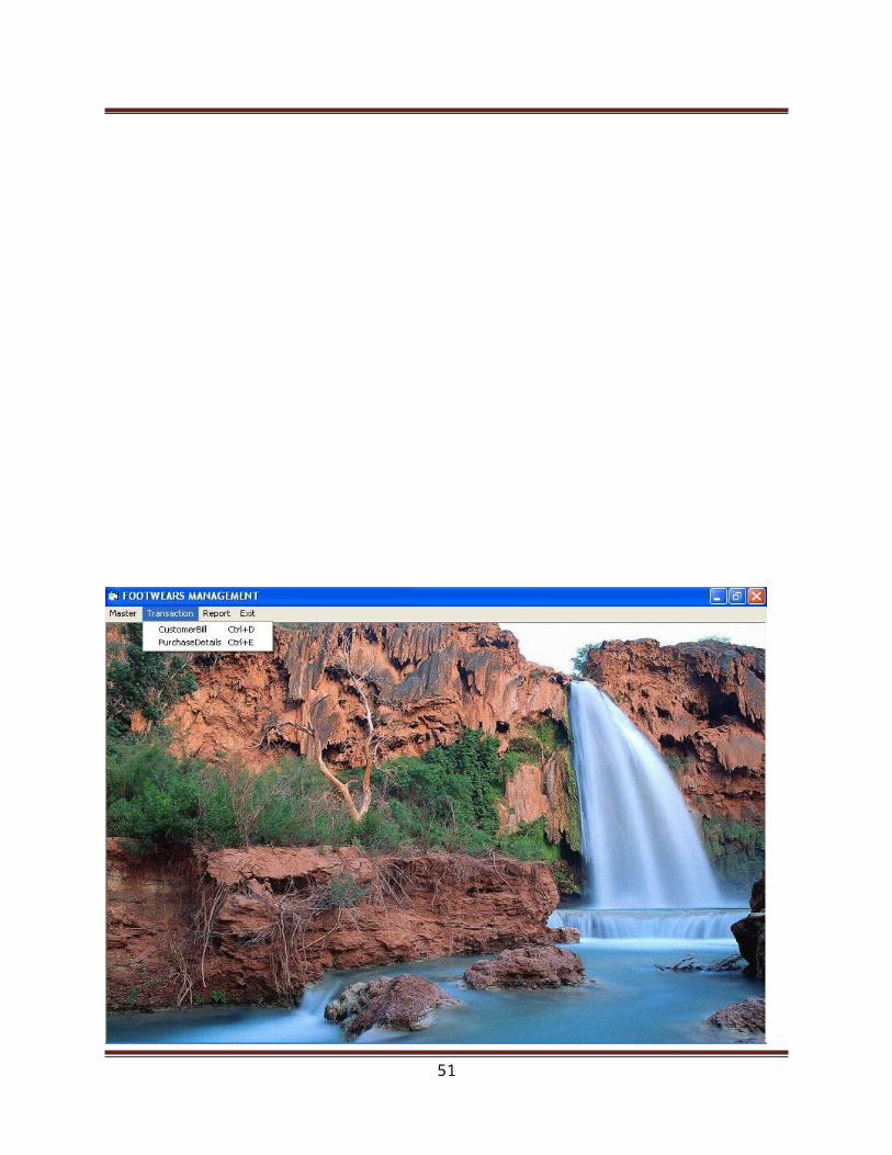
Transaction modules
Customer Bill Details
Purchase Details
Reports are
Employee Details
Supplier Details
Item Details
Customer Bill Details
Purchase Details
2

1.2 Organization Profile
The Project entitled Footwear Management System is done for Limra Footwear
Situated in No.4, Municipal Complex Upstairs, Old Bus stand, Tirupur. The proprieter,
Mr.A.K.Shanavaz has started it in the year 1988. For the past 20 years, the business is
running successfully. It is a famous footwear shop in Tirupur.
The main objectives of this shop are
Quality Maintenance
Reasonable Price
Regular Customers
New Varieties
Discount Sales
This shop solds items such as gents chappals, ladies fashion chappals , children
chappals, school shoes, sport shoes, socks, shoe polish, shoe cleaner etc.
The business was started with a low budjet. But today, it is a successfully running
business. Gift Items are also offered for the customers in festival days. Good Relationship
is maintained between the customers and the owners of the shop. Employees are working
in this shop as Incharge, Helpers, Supervisors etc. They are given good salaries.
This concern provides best quality of products only. Because of its quality, this
concern has a good name among the society.
3

2. SYSTEM ANALYSIS
In this phase the existing system has been studied completely. In this study, various
activities involved in the manual system are analyzed and most feasible details for developing
the new system is absorbed.
2.1 Existing System
The study of existing system deals with the work needed to carry out the preliminary
investigation. The study of the system can be performed only on the existing system. Since, it
gives an insight in the structure and functioning of the system.
In the existing system, the date are maintained manually and also the reports. So, the
accessing of information is very slow that require lot of manpower to organize the date for a
consolidated report. Queries from the higher authorities are not easy to be replied. Since the
work done manually, there are many difficulties. They are as follows,
Drawbacks of Existing system
More workers are needed.
Possibilities of computation errors.
Involves lot of paper to maintain the data.
Possibilities of redundant data.
Constant updating is difficult.
They have to refer large amount of data to answer a single query.
It is a time consuming process and not easy.
[
4

2.2 Proposed System
The previous section highlights the limitations of the existing system. The problem was
formulated based on the existing system and the user requirements. The present system has lot of
difficulties and the major one being that the work is done manually. But the proposed system has
been designed to overcome these facilities. This new software package is completely done in
menu driven basis and it is also developed to generate various reports according to the need.
In the proposed system, except the data entry and device setting, no other human
interventions are required.
Advantages of proposed system
It is completely menu driven.
It contains many properly designed input screens.
It smoothens up the process of data entry of the users.
It is easy to use for the end users.
It facilitates the printing of reports
It is user friendly.
Quick retrieval of information.
Validation checks are performed then and there.
This would reduce the error that might occur in data entry. Even though there is an error
and it will be a parallax error not a computational error.
5

Objective of the Proposed System
The objective of the system is to process the data on input details, and give the necessary
reports. The application is fully functional, only if satisfies the objectives mentioned.
Studying the existing manual system has identified the exact nature of the problem. Also
it has been decided that the problem in the existing system can be solved only by
computerization. The existing system has been studied by initial investigation through
observation, record searching and interviewing. All the manual process in the system are
grouped and the files are maintained, which are altered to store the records in computerized
system.
2.3 Feasibilty Study
Feasibility study is the evaluation of system regarding is workability, impact on the
organization, ability to meet the user needs and effective use of resources. It is both necessary
and prudent to evaluate the feasibility of a project at the earliest possible time. Months or Years
of effort, thousands and millions of dollars, and untold professional embarrassment can be
averted if an ill-conceived system is recognized early in the definition of phase.
Feasibility and risk analysis are related in many ways.If project risk is great, the
feasibility of producing quality software is reduced. During product engineering, however, we
concentrate our attention on primary areas of interest.
Technical Feasibility
Technical Feasibility is the need of hardware and software ,which are needed to
implement the proposed system in the organization. Technical requirements are to be fulfilled to
make the proposed system work. This should be necessarily predetermined so as to make the
system more components.
It is the study that determines whether the work for the project can be done with
current equipment, existing software technologies, and available personnel.
6

Technical feasibility is the most difficult area to assess at the stage of the system
development process. Because objectives, functions and performance are somewhat hazy,
anything seems possible if the right assumptions are made.
Technical feasibility centers on the existing computer system (hardware, software,
etc……) and to what extent it can support the proposed addition .For example, if the current
computer is operating at 80% capacity. This involves, additional hardware (RAM and
PROCESSOR) will increase the speed of the process.
Operational Feasibility
During feasibility analysis operational study is must. Because according to software
engineering principles operational feasibility or in the other words usability should be very high.
A thorough analysis is done and found that system is operational. Managing the time and work
system is possible to develop operationally.
Behavioral Feasibility
Behavioral feasibility speaks about how strong a reaction the programmer is likely to
have toward or against the development of system.Since the programmers are well exposed to
the system, it will be feasible for them to work on. Therefore, the system to be computerized is
also behaviorally feasible.
Economical Feasibility
Economical Feasibility deals with the analysis of cost against benefits i.e. whether the
benefits to be enjoyed due to the new system are worthy, when compared to the costs to be spent
on the system.
Economics justification is generally the “bottom-line” consideration fo r most system,
long-term corporate income strategies, impact on other profit centers or products, cost of the
resources needed for development, and potential market growth. Hence this project was
economically justified for development in this organization.
7

Especially in the present scenario, where the objective is towards compatibility, reduced
cost is weighed against the ultimate income or benefit derived from the developed system.
This system has been implemented such that it can be used to analysis the traffic. So it
does not require any extra equipment or hardware to implement. So it is economically feasible to
use.
Legal Feasibility
Legal Feasibility encompasses a broad range of concern that includes contacts, liability,
infringement and myriad other taps frequently unknown to the technical staff. A determination of
any infringement, violation or liability that could result from the development of the system.
8

3. SYSTEM SPECIFICATION
3.1 Hardware Specification
Processor : Pentium III
Speed : 800 MHz
RAM Capacity : 128 MB
Mother Board : Intel
Disk Space : Min 40 GB
Monitor : 15” COLOR Monitor
Mouse : Logitech Mouse
Key Board : Frontech 101 Key Board
3.2 Software Specification
Front End : VB 6.0
Back End : MS-ACCESS 7.0
Platform : Windows 98
9

Language Description
Visual Basic is an ideal programming language for developing sophisticated
professional application for Microsoft Windows.
It makes use of Graphical User interface for creating robust and powerful application
which enables the users to interact easily with an application.
Visual Basic provides many aspects such as easier comprehension, user friendliness
and faster application development, which help the developer to design the
application more effectively.
Visual Basic 6.0 provides the facilities such as log-in dialog form, splash form,
ODBC log-in form , browser form, query form, option dialog form, VB data form
wizard form which enable the developer to design the application more effectively.
MDI form allows having a relation between parent and child forms.
Crystal Report and Data Report Features of Visual Basic help in generating various
type of reports.
More number of master tables can be stored under the Database in MS-ACCESS,
which helps to store data for Visual Basic. This facility provides an easy and efficient
retrieval database.
The back end tool used in Microsoft Access 7.0 , which is the component of the very
famous package Microsoft Office. This Back End is mostly used for developing
commercial software.
Visual Basic 6.0 is a very popular Microsoft product developed by Microsoft
Corporation. This front-end tool is mainly used for developing both Client Server Application
and Desktop Application . This software works under Windows 95, Windows 98 and Windows
NT platforms. This is one of efficient language improved from the Basic language. Visual Basic
includes varieties of open active controls for user interface to design application forms.
10

Ms-Access 7.0
MS-Access is a fully featured database management system that let us to
collect, find, display and prints information about our personal and business life. The
amount and variety of information it can deal is huge. It is easier to work with simple,
professional looking information systems in a matter of moments. Access comes with
wizards and a variety of database element that let us to set many common tools with only a
few clicks of the mouse. Databases are the key ingredients of Access.
MS-Access is a powerful Relational Database Management System (RDBMS). Visual
Basic implements data access by the same database engine that powers Microsoft Access.
Access is an Object-Oriented Database. Access stores all the database objects, tables, forms,
queries, macros and modules in a single database.
The Microsoft Access Database is made up of 7 major components:
Tables
Relationships
Queries
Forms
Reports
Macros
Modules
The following gives a quick overview of each component.
Tables
The tables are the backbone and the storage container of the data entered into the
database. If the tables are not set up correctly, with the correct relationships, then the database
may be slow, give you the wrong results or not react the way you expect. So, take a bit of time
when setting up your tables.
11

The tables that contain data look a bit like a table in Microsoft® Word or a Microsoft®
Excel Spreadsheet, when opened. They have columns and rows as does a table in Microsoft®
Word and an Excel worksheet. Each of the columns will have a field name at the top and each of
the rows will represent a record.
Relationships
Relationships are the bonds you build between the tables. They join tables that have
associated elements. To do this there is a field in each table, which is linked to each other, and
have the same values.
Queries
Are the means of manipulating the data to display in a form or a report. Queries can sort,
calculate, group, filter, join tables, update data, delete data, etc. Their power is immense. The
Microsoft Access database query language is SQL (Structured Query Language). The need to
know SQL is not required in the early stages of learning Access. Microsoft® Access writes the
SQL for you, after you tell it what you want, in the Design view of the queries window.
Forms
Forms are the primary interface through which the users of the database enter data. The
person who enters the data will interact with forms regularly. The programmer can set the forms
to show only the data required. By using queries, properties, macros and VBA (Visual Basic for
Applications), the ability to add, edit and delete data can also be set. Forms can be set up and
developed to reflect the use they will be required for.
Reports
Reports are the results of the manipulation of the data you have entered into the database.
Unlike forms, they cannot be edited. Reports are intended to be used to output data to another
device or application, i.e. printer, fax, Microsoft Word or Microsoft Excel.
12

Macros
Macros are an automatic way for Access to carry out a series of actions for the database.
Access gives you a selection of actions that are carried out in the order you enter. Macros can
open forms; run queries, change values of a field, run other Macros, etc. the list is almost
endless.
Modules
Modules are the basis of the programming language that supports Microsoft® Access,
The module window is where you can write and store Visual Basic for Applications (VBA).
Advanced users of Microsoft® Access tend to use VBA instead of Macros. If you would like to
learn VBA, I have a simple step by step lessons.
All of the above components are persistent; this means that changes are saved when you
move from one component to another, not when the database is closed, as in a Microsoft Word
Document.
Limitations
The total size of a database file (.MDB) is limited only by the storage capacity of your PC
(Microsoft quote the maximum database size of 2 Gigabyte (2000 Megabytes)). These figures
are for pre 2007 versions of Microsoft Access.
Features of Microsoft Access
USER-defined functions are embedded.
FILE-locking facilities are available.
Sharing database.
Structured Query Language (SQL).
13

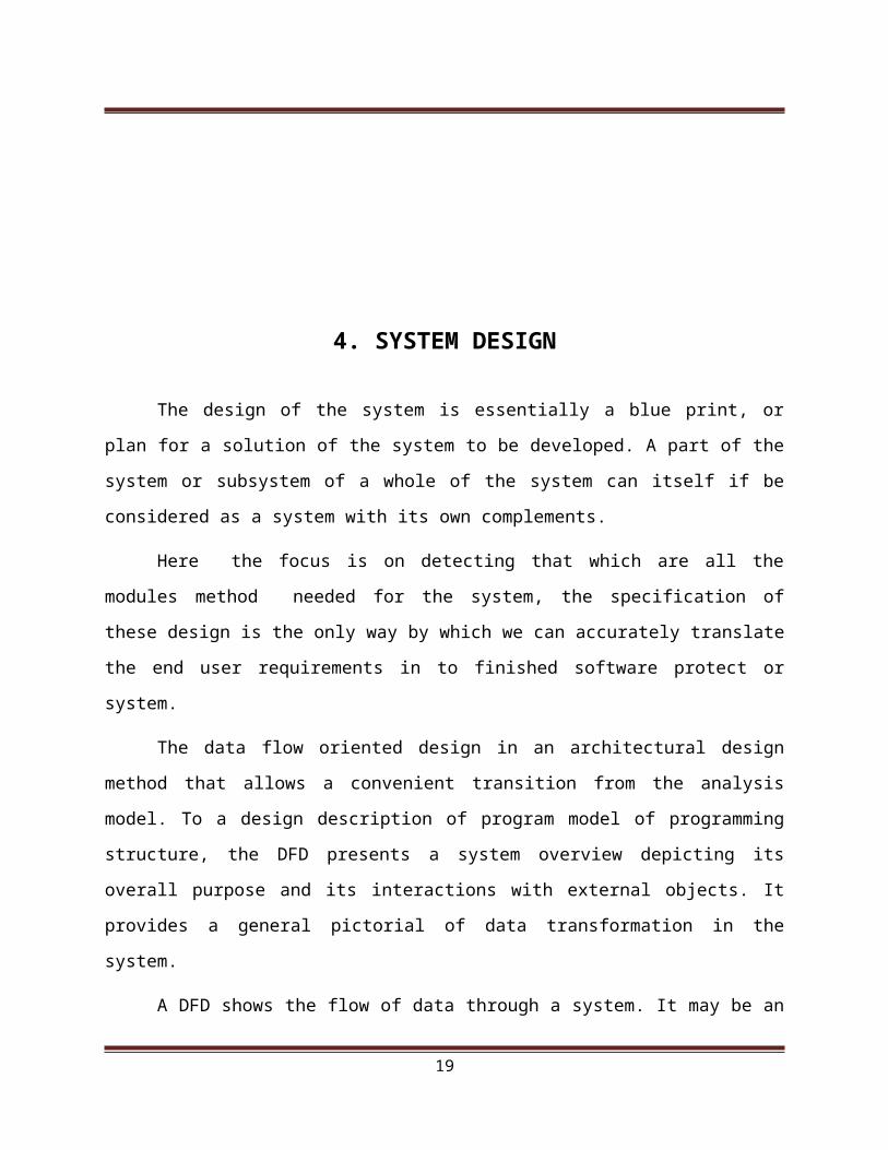
4. SYSTEM DESIGN
The design of the system is essentially a blue print, or plan for a solution of the system to
be developed. A part of the system or subsystem of a whole of the system can itself if be
considered as a system with its own complements.
Here the focus is on detecting that which are all the modules method needed for the
system, the specification of these design is the only way by which we can accurately translate
the end user requirements in to finished software protect or system.
The data flow oriented design in an architectural design method that allows a convenient
transition from the analysis model. To a design description of program model of programming
structure, the DFD presents a system overview depicting its overall purpose and its interactions
with external objects. It provides a general pictorial of data transformation in the system.
A DFD shows the flow of data through a system. It may be an organization, a manual
procedure ,software system, hardware system or any combination of these. A DFA shows the
movement of the data through the different transformations, which are the process in the system.
DFD are made up of a number of symbols which represent system components process data
storage and data flow and external entities.
4.1 Fundamentals of Design concept
Software design is both process and model. The design process is a set of iterative steps
that enable the designer to describe all aspects of the software to be built. A set of fundamental
design concepts have been evaluated each of which provides the software designer with a
foundation from which more sophisticated design methods can be applied. The following design
concepts can be regarded as criteria for an efficient system.
14

Abstraction
Considering a modular solution to a problem, many levels of abstraction can be posed. At
lower level of abstraction, a more procedural orientation is taken. Problem oriented terminology
in an effort to state in a manner that can be directly implemented.
Refinement
The architecture of a program is developed by successively refining levels of procedural
detail. The process of program refinement is analogous to the process of refinement and
partitioning that is used during required analysis. Refinement is the process of elaboration.
Refinement causes the designer to elaborate on the original statement, providing more and more
detail as each successive refinement occurs.
Modularity
Modularity is a single attribute of software that allows the program to be intellectually
manageable. The software is divided into separately named and addressable components, called
modules which are integrated to satisfy problem required.
Software architecture
Software architecture is a hierarchical structure of the program components or modular
the manner in which these components interact and the structure of the data used by the
components. Software design can be aimed to drive on architectural rendering of a system. A set
OS architectural pattern enables a software engineer to reuse design-level concepts.
Control hierarchy
Control hierarchy also called program structure represents the organization of program
components or modules and implies a hierarchy of control. The tree-like diagram is the most
common diagram used to represent control hierarchy.
15

Structural partitioning
The program structure can be partitioned both horizontally and vertically partitioning
defines separate branches of the modular hierarchy for each major program function. Vertical
partitioning or factoring suggest that control or decision-making the work should be distributed
top-down in the program architecture.
Data structure
Data structure is a representation of a logical relationship among individual elements of
data. Data structure dictates the organization methods of access, degree of associatively, and
processing alternatives for information. It can be represented at different levels of abstraction.
Software procedure
Software procedure focuses on the processing details of each machine individually.
Procedure must provide a precise specification of processing, including sequence of events, exact
decision points, repetitive operations and data organization or structure.
Information hiding
Modules should be specified and designed so that information contained within a module
is inaccessible to other modules that have no need for such information. Hiding defines and
enforces access constraints to both procedural detail within a module and any local data structure
used by the module.
16

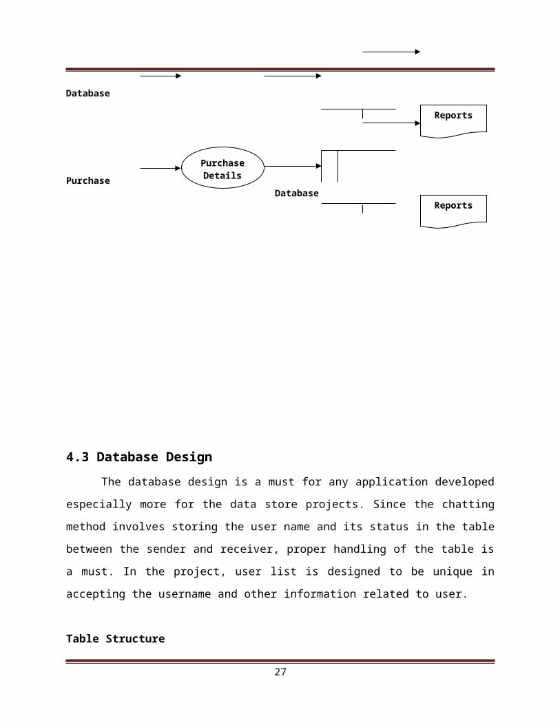
4.2 Data Flow Diagram
Data flow oriented techniques advocate that the major data items handled by a system
must be first identified and then the processing required on these data items to produce the
desired outputs should be determined. The DFD (also called as bubble chart) is a simple
graphical formalism that can be used to represent a system in terms of input data to the system,
various processing carried out on these data, and the output generated by the system. It was
introduced by De Macro (1978), Gane and Sarson (1979).The primitive symbols used for
constructing DFD’s are:
Symbols used in DF
A circle represents a process.
A rectangle represents external entity
A square defines a source or destination of the system data.
An arrow identifies dataflow.
A Double line with one end closed indicates data store
17

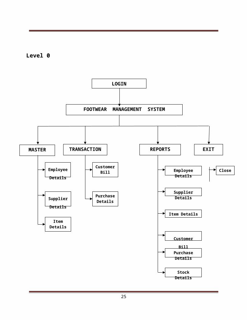
Level 0
.
18
LOGIN
FOOTWEAR MANAGEMENT SYSTEM
MASTER
Employee
Details
Supplier
Details
Item Details
Customer Bill
TRANSACTION
Purchase Details
Employee Details
Supplier Details
Item Details
Customer Bill
Purchase Details
REPORTS EXIT
Close
Stock Details
Level 1
Employee Database
Supplier Database
Item
Database Customer Database
Purchase
Database
19
User
Employee Details
Supplier
Details
Item Details
Reports
Reports
Reports
Reports
Customer Bill
Purchase Details
Reports

4.3 Database Design
The database design is a must for any application developed especially more for the data store
projects. Since the chatting method involves storing the user name and its status in the table
between the sender and receiver, proper handling of the table is a must. In the project, user list is
designed to be unique in accepting the username and other information related to user.
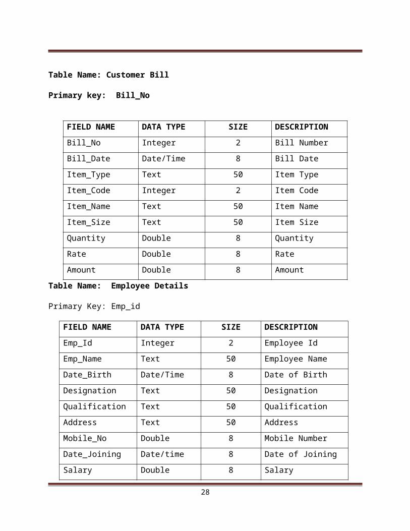
Table Structure
Table Name: Customer Bill
Primary key: Bill_No
Table Name: Employee Details
Primary Key: Emp_id
FIELD NAME DATA TYPE SIZE DESCRIPTION
Emp_Id Integer 2 Employee Id
Emp_Name Text 50 Employee Name
Date_Birth Date/Time 8 Date of Birth
Designation Text 50 Designation
Qualification Text 50 Qualification
20
FIELD NAME DATA TYPE SIZE DESCRIPTION
Bill_No Integer 2 Bill Number
Bill_Date Date/Time 8 Bill Date
Item_Type Text 50 Item Type
Item_Code Integer 2 Item Code
Item_Name Text 50 Item Name
Item_Size Text 50 Item Size
Quantity Double 8 Quantity
Rate Double 8 Rate
Amount Double 8 Amount
Address Text 50 Address
Mobile_No Double 8 Mobile Number
Date_Joining Date/time 8 Date of Joining
Salary Double 8 Salary
Table Name: Item Details
Primary Key: Item_Type
21
FIELD NAME DATA TYPE SIZE DESCRIPTION
Item_Type Text 50 Item Type
Item_Code Integer 2 Item Code
Item_Name Text 50 Item Name
Item_Size Text 50 Item Size
Price Integer 2 Price

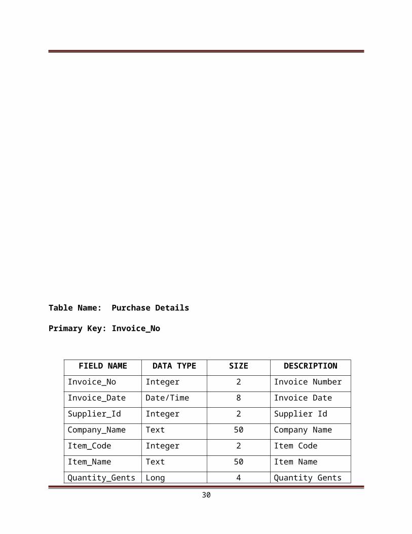
Table Name: Purchase Details
Primary Key: Invoice_No
FIELD NAME DATA TYPE SIZE DESCRIPTION
Invoice_No Integer 2 Invoice Number
Invoice_Date Date/Time 8 Invoice Date
Supplier_Id Integer 2 Supplier Id
Company_Name Text 50 Company Name
Item_Code Integer 2 Item Code
Item_Name Text 50 Item Name
Quantity_Gents Long 4 Quantity Gents
Quantity_Ladies Long 4 Quantity Ladies
Quantity_Children Long 4 Quantity Children
Rate_Gents Double 8 Rate Gents
22
Rate_Ladies Double 8 Rate Ladies
Rate_Children Double 8 Rate Children
Amount_Gents Double 8 Amount Gents
Amount_Ladies Double 8 Amount Ladies
Amount_Children Double 8 Amount Children
Total_Amount Double 8 Total Amount
Discount Double 8 Discount
Net_Amount Double 8 Net Amount
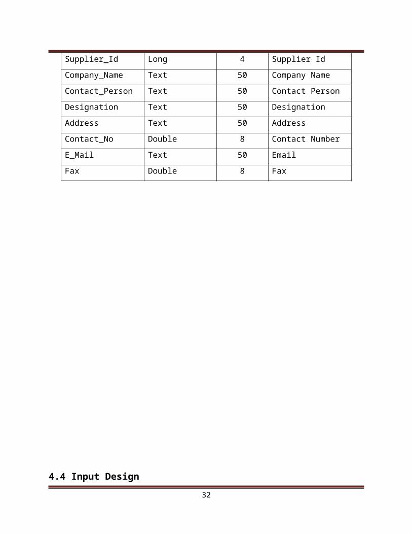
Table Name: Supplier Details
Primary Key: Supplier_Id
FIELD NAME DATA TYPE SIZE DESCRIPTION
Supplier_Id Long 4 Supplier Id
Company_Name Text 50 Company Name
Contact_Person Text 50 Contact Person
Designation Text 50 Designation
Address Text 50 Address
Contact_No Double 8 Contact Number
E_Mail Text 50 Email
Fax Double 8 Fax
23

4.4 Input Design
Input design is the process of converting user-originated inputs to a computer based
format. Input design is one of the most expensive phases of the operation of computerized
system and is often a major problem of a system.
In the project, the input design is made in various forms with various methods. During
each of input data, guidelines are provided to the user to avoid incorrect and inaccurate entry.
The input screen should be user- friendly, so that everyone can access the option without having
the computer system knowledge. In the project, each and every option has its input screen. The
option can be selected using menus given.
4.5 Output Design
Output design generally refers to the results and information that are generated by the
system for many end-users; output is the main reason for developing the system and the basis on
which they evaluate the usefulness of the applications. An effective output design would attract
the user more.
24
The output information must be provided in such a format that the customer can
understand. After analyzing the operations, output information required for each job are
determined. In addition to this outputs may be in the format suited to input for subsequent
processing.
In this project, the purchases details, the sales details etc. are the reports in which the
output is available.
4.6 System Study
Older system of footwear management is made of “C” language which is slow and it is not
Graphic user Interface and it is not speed comparing with Graphical Interface. The accessing of
database is also slow and has a chance for duplicate record. The proposed system has Visual Basic as
Front end and MS-Access as back end which uses the Graphical User Interface. It was very user
friendly to work and the data are called accurately and quickly. And working of our project is easy to
handle.
4.7 Development Approach
System development design involves identifying the software components, decoupling
and decomposing them into processing modules and conceptual data structure and specifying the
interconnection among components.
System architecture is the design or set of a relations between the parts of a system. There
is no strict definition of which an aspect constitute system architecture, and various organizations
define it in different ways.
System architecture is primarily concerned with the internal interfaces among the system
components or subsystem, and the interface between the system and its external environment,
especially the user.
The internal structure of the software product and tests that attempt to break the system
are open during implementation. The architectural design is also called as internal design. The
goal of this design is to specify the internal structure and processing details, to record design
decisions.
25

5. SYSTEM DEVELOPMENT
The project work entitled Footwear Management System has been done for Foot
wears, located in Tirupur. This project is developed using visual basic 6.0 as front end and Ms-
Access as back end. The main objective of this project is to computerize the transactions.
While maintaining the data manually, there may be duplication and inconsistency in
generating the reports. Lot of time is spent in saving the data in an imperishable manner. All the
requirements overload robustness of a worker leading to very poor performance. Besides
these adding, modifying, entering can be done within a span of time. Viewing of details in any
section in the shop can be faster than doing it manually. So it is decided to computerize the
works and also trying to avoid the drawbacks.
It has various modules and sub modules like below mentioned:
5.1 Modules Description
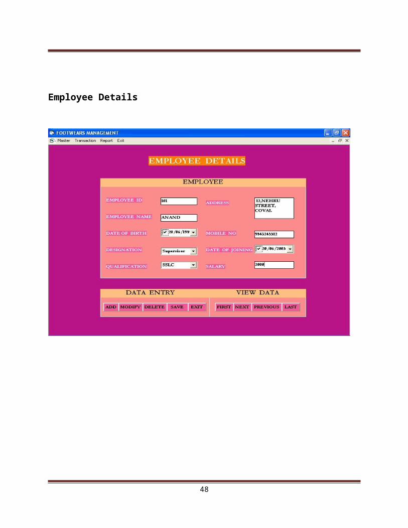
Employee Details
26
This module contains Employee Id, Employee Name, Date of birth, Designation,
Qualification, Address, Mobile Number, Date of Joining and Salary. These details are very
useful to know each and every details of a particular employee.
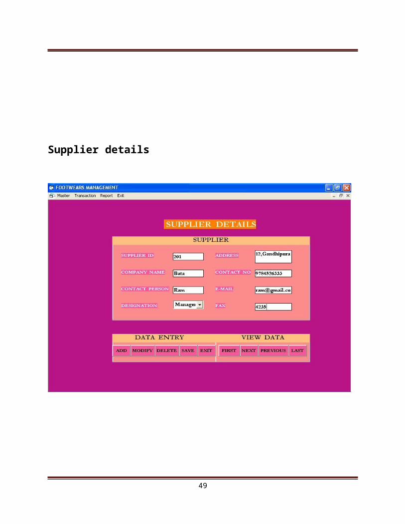
Supplier Details
This module contains Supplier Id, Company Name, Contact Person, Designation, Address,
Contact Number, E-mail Id, Fax. In this module, Supplier Id is set as the primary key. These
details are useful for purchasing items from the supplier.
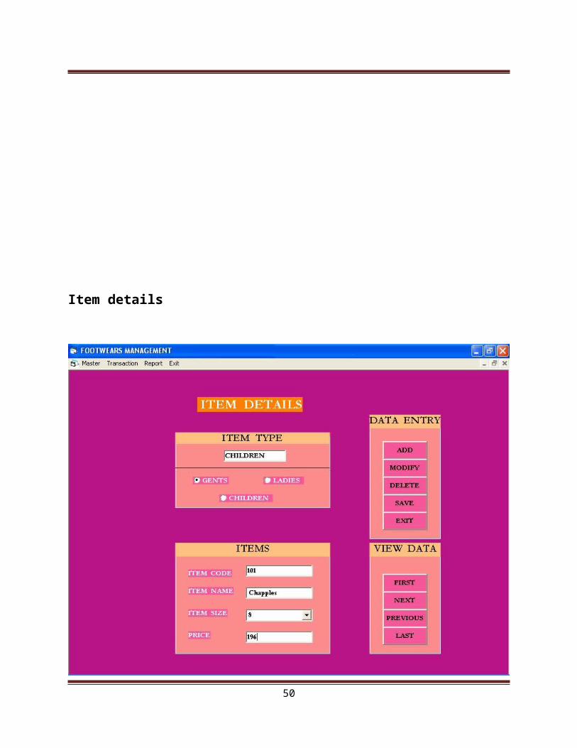
Item Details
This module contains Item Type, Item Code, Item Name, Item Size, Price. In this module,
Item code is set as the primary key. This form contains the details of the item names, item codes,
item size and prices of all the items available.
Customer Bill
This module contains Bill Number, Bill Date, Item Code, Item Name, Item Size, Item
Type, Quantity, Rate and Amount. In this module, bill number is set as the primary key. This
module helps to know the details of the customers, date on which the customers bought the items
and the quantity of the items.
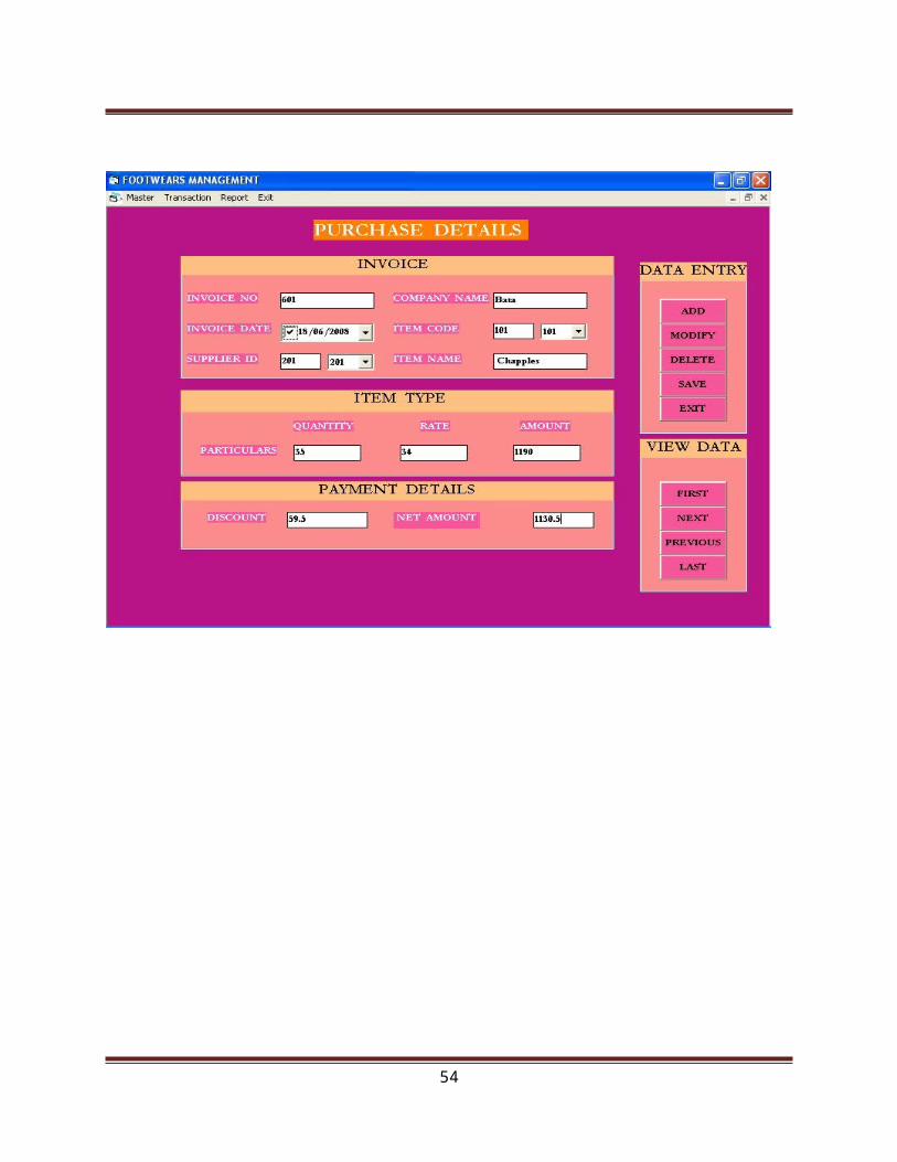
Purchase Details
This module contains Invoice Number, Invoice Date, Supplier Id, Company Name, Item
Code, Item Name, Quantity of ladies items, Quantity of gents items, Quantity of children items,
Rate of gents items, Rate of ladies items, Rate of children, Amount of gents items, Amount of
ladies items, Amount of children items, Total Amount, Discount and Net Amount.
Stock Details
It contains the information about the availability of items. This information is useful for
knowing the quantity of items available in the shop. If the quantity of items is less, then it is
useful to purchase the required items.
27
6. SYSTEM TESTING AND IMPLEMENTATION
6.1 System Testing
A strategy for software testing integrates software test and design methods into a well-
planned series of steps that results in the successful construction of software. A software design
strategy should be flexible enough to promote creativity and customization that are necessary to
adequately test all the large software based system. It should also promote reasonable planning
and progresses. The objective of testing is as follows
Testing is the process of executing a program with the intention of finding an error.
A good test case is one that has a high probability of finding an undiscovered error.
A successful test is that one of that covers an undiscovered error.
System testing is the stages of implementation, which is aimed at ensuring that the
system works accurately and efficiently before the line operation comments. Testing is vital to
the success of the system. A series of testing is performed before the system is ready for user
acceptance testing.
28

Unit Testing
Unit test is one of the tests and unrecovered error is limited by the constrained scope
established for unit testing. In unit testing, each program unit is tested individually.
So any errors in a unit are debugged. Sample data is given for unit testing. The unit
results are recorded for further reference. During unit testing the function of the program unit,
validation and limitation are tested.
Validation Testing
Validation succeeds where software function is in a manner that can be
reasonably accepted by the user. Steps taken during software design and testing can greatly
improve the probability of successful integration in the large system. In the project, the valid
password must be entered to enter the main screen. Thus validation testing is performed.
Acceptance Testing
The acceptance is the final stage of testing phase. This is done by the user. The
developed project is given to user and is tested with live data. Various possibilities of the data
are entered and response from the system is tested. Once the acceptance testing is signed off by
the client, then we can successfully implement the system.
Integration Testing
Integration testing involves integrating the components of the software system
into functioning part, which requires careful planning so that modules are available, when
needed. The integration strategy dictates the order in which modules must be available and thus
exerts a strong influence on the order in which modules are written, debugged and unit tested.
This testing demonstrates the viability of the evolving system.
6.2 System Implementation
System implementation is the stage which is very important in the life cycle of the new
system. Implementation simply means conversion of one aspect of implementation.
29
The first step in implementing the system is to get the approval from the system manager.
Even after the system implementation, the requirement of user may change in the future. The
software is designed and developed flexibly. So that it can be subjected to further changes also.
The more complex is the system being implementation, the more involved will be the
system analysis and design efforts.
6.3 System Maintenance
Visual Basic 6.0 is a very popular Microsoft product developed by Microsoft
Corporation. This front-end tool is mainly used for developing both Client Server Application
and Desktop Application. This software works under Windows 95, Windows 98 and Windows
NT platforms. This is one of efficient language improved from the Basic language. Visual Basic
includes varieties of open active controls for user interface to design application forms.
7. CONCLUSION
The project entitled FOOTWEAR MANAGEMENT SYSTEM mainly contributes to
provide information about the footwear shop. This project is flexible and can be easily
understood to anybody, who newly works with the system. The system is fully user interactive
The currently developed system is found to be working accurately. It is tested for its
effectiveness, flexibility, accuracy and user friendly. The system is found to be successfully
running under the real environment. The new system is developed with much attention over its
worth and steadiness.
This project provides easy retrieval of information about the items available. Reports from
the system provides complete business information to the shop, which helps them to take any
future changes in the daily transactions to improve the efficiency of the process.
30

8. SCOPE FOR FUTURE ENHANCEMENT
This system is very flexible so the maintenance and future enhancements based on the
changing environment and requirements can be incorporate easily. Any changes that are likely
cause system failures are presented with security measures.
In order to make modifications effectively, there should be good communication between
customer and the organization. Thus valuable suggestion supplied can be included in the
system .Since Visual Basic and Access are flexible tools, we can easily incorporate any modular
program into the application. Thus even after the development phase, design and development of
new application and their integration with the existing one can be carried out with least effort.
Addition reports can be added with the system to show the growth of the particular field
or for the whole company.
31
BIBILIOGRAPHY
Books Referred
Curtis L. Smith Database Programming with Visual Basic 6.0 Sam’s
Publication, 1998, I edition
Gary cornell, Visual Basic 6.0 from the ground up, TATA MCGRAW Hill
Publication, 1991, I edition.
Ron Mansfield, Working with Access, TATA McGraw Hill Publication, 1997
Website Referred
www.google.com
www.altavista.com
www.a1vbcode.com
32
LOGIN FORM
33

34
Employee Details
35

36
Supplier details
37
Item details
38

39

Customer bill
40

Purchase details
41

42
REPORTS
43

44

45

46

47
48
SAMPLE CODING
49
Dim db As Database
Dim rs As Recordset
Private Sub cboDesignation_KeyPress(KeyAscii As Integer)
If KeyAscii = 13 Then
cboQualification.SetFocus
End If
End Sub
Private Sub cboQualification_KeyPress(KeyAscii As Integer)
If KeyAscii = 13 Then
txtAddress.SetFocus
End If
End Sub
Private Sub cmdAdd_Click()
Text_Clear
txtEmpid.SetFocus
rs.AddNew
End Sub
Private Sub cmdDelete_Click()
If rs.RecordCount = 0 Then
MsgBox " There is No Record ", vbSystemModal, " FOOTWEAR"
Else
rs.Delete
Text_Clear
MsgBox " Record Is Deleted Successfully ", vbSystemModal, " FOOTWEAR "
50
rs.MoveFirst
Text_Load
End If
End Sub
Private Sub cmdExit_Click()
Unload Me
End Sub
Private Sub cmdFirst_Click()
If rs.RecordCount = 0 Then
MsgBox " There is No Record ", vbSystemModal, " FOOTWEAR"
Else
rs.MoveFirst
Text_Load
End If
End Sub
Private Sub cmdLast_Click()
If rs.RecordCount = 0 Then
MsgBox " There is No Record ", vbSystemModal, " FOOTWEAR"
Else
rs.MoveLast
Text_Load
End If
End Sub
51

Private Sub cmdModify_Click()
If rs.RecordCount = 0 Then
MsgBox " There is No Record ", vbSystemModal, " FOOTWEAR"
Else
Text_Load
If MsgBox(" You Want To Modify This Record ", vbYesNo + vbQuestion) = vbYes Then
rs.Edit
Text_Load
End If
End If
End Sub
Private Sub cmdNext_Click()
If rs.RecordCount = 0 Then
MsgBox " There is No Record ", vbSystemModal, " FOOTWEAR"
Else
rs.MoveNext
End If
If rs.RecordCount > 0 Then
If rs.EOF = True Then
rs.MoveLast
MsgBox " This is The Last Record ", vbSystemModal, " FOOTWEAR"
End If
End If
Text_Load
52

End Sub
Private Sub cmdPrevious_Click()
If rs.RecordCount = 0 Then
MsgBox " There is No Record ", vbSystemModal, " FOOTWEAR"
Else
rs.MovePrevious
End If
If rs.RecordCount > 0 Then
If rs.BOF = True Then
rs.MoveFirst
MsgBox " This is The First Record ", vbSystemModal, " FOOTWEAR"
End If
End If
Text_Load
End Sub
Private Sub cmdSave_Click()
rs.Fields(0) = txtEmpid.Text
rs.Fields(1) = txtEmpname.Text
rs.Fields(2) = DTPicker1.Value
rs.Fields(3) = cboDesignation.Text
rs.Fields(4) = cboQualification.Text
rs.Fields(5) = txtAddress.Text
rs.Fields(6) = txtMobileno.Text
rs.Fields(7) = DTPicker2.Value
53
rs.Fields(8) = txtSalary.Text
rs.Update
MsgBox " Record is Saved Successfully ", vbSystemModal, " FOOTWEAR"
End Sub
Private Sub DTPicker1_KeyPress(KeyAscii As Integer)
If KeyAscii = 13 Then
cboDesignation.SetFocus
End If
End Sub
Private Sub DTPicker2_KeyPress(KeyAscii As Integer)
If KeyAscii = 13 Then
txtSalary.SetFocus
End If
End Sub
Private Sub Form_Load()
Set db = OpenDatabase("C:\FOOTWEAR\Footwear.mdb")
Set rs = db.OpenRecordset("Employee_Details", dbOpenDynaset, dbOpenDynamic)
End Sub
Public Function Text_Load()
txtEmpid.Text = rs.Fields(0)
txtEmpname.Text = rs.Fields(1)
DTPicker1.Value = rs.Fields(2)
cboDesignation.Text = rs.Fields(3)
cboQualification.Text = rs.Fields(4)
54

txtAddress.Text = rs.Fields(5)
txtMobileno.Text = rs.Fields(6)
DTPicker2.Value = rs.Fields(7)
txtSalary.Text = rs.Fields(8)
End Function
Public Function Text_Clear()
txtEmpid.Text = ""
txtEmpname.Text = ""
DTPicker1.Value = ""
cboDesignation.Text = ""
cboQualification.Text = ""
txtAddress.Text = " "
txtMobileno.Text = " "
DTPicker2.Value = ""
txtSalary.Text = ""
End Function
Private Sub txtAddress_KeyPress(KeyAscii As Integer)
If KeyAscii = 13 Then
txtMobileno.SetFocus
End If
End Sub
Private Sub txtEmpid_KeyPress(KeyAscii As Integer)
If KeyAscii = 13 Then
55

txtEmpname.SetFocus
End If
End Sub
Private Sub txtEmpname_KeyPress(KeyAscii As Integer)
If KeyAscii = 13 Then
DTPicker1.SetFocus
End If
End Sub
Private Sub txtMobileno_KeyPress(KeyAscii As Integer)
If KeyAscii = 13 Then
DTPicker2.SetFocus
End If
End Sub
56


![CLINIC MANAGEMENT SYSTEM: WAR]) MANAGEMENT SYSTEM NORAINI ...](https://static.fdocuments.net/doc/165x107/61d2b752737cab31ea7c506d/clinic-management-system-war-management-system-noraini-.jpg)