Foot Switches - ASA Schalttechnik - Foot Switches.pdf · 4 ASA foot switches Ranging from standard...
32
Foot Switches
Transcript of Foot Switches - ASA Schalttechnik - Foot Switches.pdf · 4 ASA foot switches Ranging from standard...
Foot Switches

2
Made in Germany
ASA Schalttechnik – we drive the industry Are you looking for reasonably priced technology that works smoothly, that fully meets your requirements and that offers a long service life with constant high performance as you would expect? And, on top of this, a range of products that is convincing in terms of both breadth and depth? Then we have the good news that you have been waiting for: At ASA Schalttechnik we do everything imaginable so that your wishes become reality.
Our team consists of doers, creative minds and service experts: Experienced pro-fessionals who live and breathe quality, who draw on unlimited resources on 2,000 m2 production space, are dedicated to detail and who get to the heart of things when it comes to control and switching technology. Alltogether, refreshingly pragmatic, truly German, straightforward and good.
We love challenges Our all-round competence is reflected in our tried and tested standard products that can be delivered at short notice ex-factory. But also in our individual custom-made solutions manufactured in small volumes. Consequently, we are a competent partner and, when the need arises, a flexible manufacturer of niche products, developed and designed in cooperation with our customers.
ASA Schalttechnik proudly stands for this philosophy and delivers every time. As a family-owned enterprise, our products offer quality “Made in Germany”.
• Limit Switches
• Switchgear
• Foot Switches
• Safety Switches
• Medical switching devices
• Magnetic Switches
• Level Switches
• Special switching devices
Our product range Mechanical, magnetic and electronic switchgear for machinery and plant engineering – control and automation technology, fire protection technology, medical technology and much more:

3
made
in
Germany
Quality is a continuous process Or to put it another way, it’s a never-ending process – an infinite cycle of testing, analysing, understanding, learning, optimising and documenting. That’s life. Our suppliers also support us with this process, as it’s the only way to make quality management work. And we make sure to adhere to it: With staying power since 1975.
Enviromental protection is a point of honour Save electricity, water and heating energy. Avoid waste and plan responsible use of raw materials in production. For our team, ecology is not just hype – it plays an important part in our day-to-day operations, also with regard to RoHS, REACH and recycling. Beneficial to nature, beneficial to us all.
It’s the team that makes the difference ASA Schalttechnik: People who achieve – hands-on people who think for them-selves and who inspire us with their energy, ideas and experience. Whether they work in our production department, in customer relations or in management, our committed staff does everything to achieve best prices, top-of-class products, best delivery times and excellent services. And that’s a promise!
4
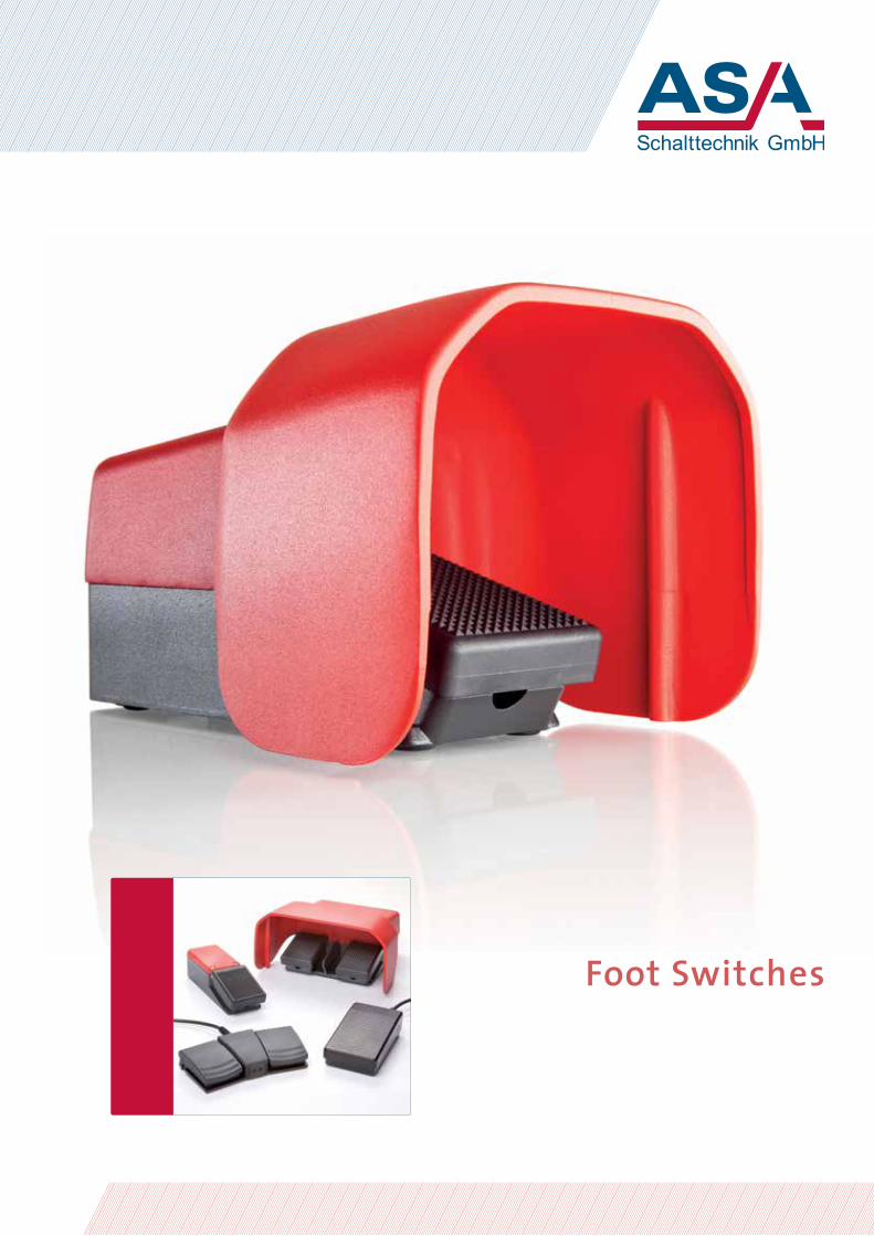
ASA foot switches Ranging from standard switchgear to special designs: ASA foot switches are used in industry and also in medical applications. With a great deal of success wherever operators have to keep their hands free and trigger processes with their foot.
Stable, non-slip, ideal ASA foot switches are functional, safe and made from high-quality materials. Mechanical stability and modern industrial design are combined and the flexible switch lines offer a suitable model for every application.
Ease of operation and precision • Many power levels and different switching systems.
• Housings, switch inserts and pedal functions also available in especially sturdy versions – for intensive industrial use.
• The pedal surfaces are especially non-slip and designed flat for safety and ergonomics.
• Of course they are RoHS-compliant.
Please also note the technical details on the following pages.
ASA foot switches

5
Foot switch lines – overview: FM – FK – FL – FS
The FM line includes miniature foot switches
FM1 Plastic foot switch, miniature design, 1-pedal, no foot guard
FM1…U Plastic foot switch, miniature design, 1-pedal, with foot guard
FM2 Plastic foot switch, miniature design, 2-pedal, no foot guard
FM3 Plastic foot switch, miniature design, 3-pedal, no foot guard
The FK line includes small foot switches
FK1 Plastic foot switch, small design, 1-pedal, no foot guard
FK1...U Plastic foot switch, small design, 1-pedal, with foot guard
The FL line includes lightweight foot switches
FL1 Plastic foot switch, lightweight design, 1-pedal, no foot guard
FL1…U Plastic foot switch, lightweight design, 1-pedal, with cast aluminium foot guard
The FS line includes heavy foot switches
FS1 Cast aluminium foot switch, heavy design, 1-pedal, no foot guard
FS1…U Cast aluminium foot switch, heavy design, 1-pedal, with cast aluminium foot guard
FS2 Cast aluminium foot switch, heavy design, 2-pedal, no foot guard
FS2…U Cast aluminium foot switch, heavy design, 2-pedal, with cast aluminium foot guard
FS3 Cast aluminium foot switch, heavy design, 3-pedal, no foot guard
FS3…U Cast aluminium foot switch, heavy design, 3-pedal, with cast aluminium foot guard
The individual product lines offered by ASA include a wide selection of other switch designs. Can’t find a standard solution to match your individual requirements? We look forward to discussing your needs and providing customised special configurations.
6
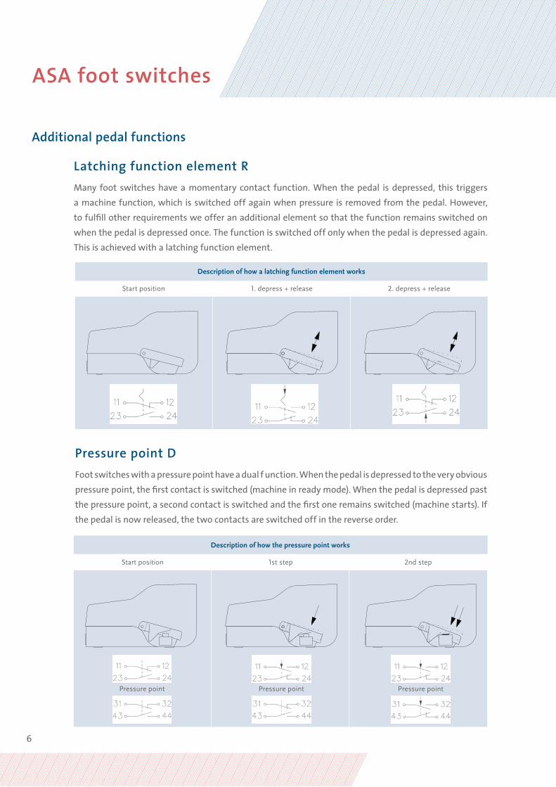
Latching function element RMany foot switches have a momentary contact function. When the pedal is depressed, this triggers a machine function, which is switched off again when pressure is removed from the pedal. However, to fulfill other requirements we offer an additional element so that the function remains switched on when the pedal is depressed once. The function is switched off only when the pedal is depressed again. This is achieved with a latching function element.
Pressure point DFoot switches with a pressure point have a dual f unction. When the pedal is depressed to the very obvious pressure point, the first contact is switched (machine in ready mode). When the pedal is depressed past the pressure point, a second contact is switched and the first one remains switched (machine starts). If the pedal is now released, the two contacts are switched off in the reverse order.
Description of how a latching function element works
Start position 1. depress + release 2. depress + release
Additional pedal functions
Description of how the pressure point works
Start position 1st step 2nd step
Pressure point Pressure point Pressure point
ASA foot switches

7
Anti-trip lever mechanism S If a foot switch is depressed accidentally, it can have serious consequences for plant and equipment. Accidental triggering can be prevented by a foot switch with a lever. It consists of a high-grade cast aluminium alloy that functions as a safety device. The pedal of the foot switch can be depressed only when the lever is pressed back with the tip of the foot. When the pedal is released, the lever straightens up again automatically.
Protection options
Description of how the anti-trip lever mechanism works
press back depress straightens up automatically

8
TYPE FM Foot switch, miniature design
Number of pedals 1 1 Pedal
2 2 Pedals
3 3 Pedals
Switch insert SU1 Snap-action switch, 1 changeover contact
SU2 Snap-action switches, 2 changeover contacts
Connection L Solderable, unwired
F Permanently connected supply cable
Example: FM1 SU1R F2
Foot switches in the FM lineASA foot switches in the FM line are miniature plastic foot switches. They are used in device and equipment engineering and also in medical applications. They are characterised by their stur-dy construction, technical versatility, functionality and ergonomic design. Switches in the FM line provide maximum functions within a small area. For example, one pedal can activate two switch inserts – also in two steps with a pressure point or via a latching function.
Type key for FM line, standard designs
Additional pedal function R Latching function element
D Pressure point
Protection class 1 IP 43
2 IP 65
Foot guard U Foot guard
FM foot switches

9
Technical specifications for foot switches in the FM line
Regulations: ASA foot switches are manufactured in accordance with the applicable regulations IEC/EN 60204 and IEC/EN 60947-5-1.
Design: 1, 2 and 3-pedal plastic foot switch, miniature design, free-standing on non-slip elastic feet or fixed by screws from below. Multi-pedal versions on request.
Housing: Thermoplastic PA 6.6 glass fibre-reinforced, black grey. More colours on request.
Pedal: Thermoplastic PA 6.6 glass fibre-reinforced, black grey. More colours on request.
Top: Thermoplastic PA 6.6 glass fibre-reinforced, black grey. More colours on request.
Foot guard: Sheet steel, powder-coated-red RAL 3000. More colours on request.
Base plate: Aluminium 4 mm thick, powder-coated-black grey RAL 7021. More colours on request.
Channel: Sheet steel, powder-coated-black grey RAL 7021. More colours on request.
Connection: • Solderable, unwired • PVC control cable, structure corresponds to H05VV-F, S=0.5 mm∞, black, length 2 m
Cable inlet: Cable gland with protective spring coil, available as special design with protective rubber sleeve
Protection class: IP 43 or IP 65 according to IEC/EN 60529. Higher protection classes on request.
Switching contact: IP 54 according to DIN 40050; as special design IP 65 according to DIN 40050, with incremental
Switching function: • Momentary • Maintained • Sequence circuit with pressure point
Switching cycles: min. 10 million
Working temperature: -20 °C to +80 °C, other temperature ranges on request
Switch inserts SU1 SU2
Switch type: 1 changeover contact switch with single break
2 changeover contact switch with single break
Switching system: Snap-action mechanism Snap-action mechanism
Contact material: Silver Silver
Voltage: max. 250 VAC, 40-60 Hz max. 250 VAC, 40-60 Hz
Current capacity: max. 6 A max. 6 A
Approvals: UL, CSA, VDE, SEV, SEMKO UL, CSA, VDE, SEV, SEMKO

10
Type table for FM1 foot switches, standard selection
Type No. Contact Switch insertper pedal
Switching system
Latching function element
Pressure point
Lever Connection Protection class
FM1 SU1 L1 8026 0000 SU1 Snap-action _ – – Solderable IP 43
FM1 SU1 F1 8026 0100 SU1 Snap-action _ – – 3 x 0.5 IP 43
FM1 SU1 F2 8026 0105 SU1 Snap-action _ – – 3 x 0.5 IP 65
FM1 SU1R L1 8026 0002 SU1 Snap-action • – – Solderable IP 43
FM1 SU1R F1 8026 0102 SU1 Snap-action • – – 3 x 0.5 IP 43
FM1 SU1R F2 8026 0107 SU1 Snap-action • – – 3 x 0.5 IP 65
FM1 SU2 L1 8026 0001 SU2 Snap-action – – – Solderable IP 43
FM1 SU2 F1 8026 0101 SU2 Snap-action – – – 6 x 0.5 IP 43
FM1 SU2 F2 8026 0106 SU2 Snap-action – – – 6 x 0.5 IP 65
FM1 SU2R L1 8026 0003 SU2 Snap-action • – – Solderable IP 43
FM1 SU2R F1 8026 0103 SU2 Snap-action • – – 6 x 0.5 IP 43
FM1 SU2R F2 8026 0108 SU2 Snap-action • – – 6 x 0.5 IP 65
FM1 SU1DSU1 L1 8026 0004 2 x SU1 Snap-action – • – Solderable IP 43
FM1 SU1DSU1 F1 8026 0104 2 x SU1 Snap-action – • – 6 x 0.5 IP 43
FM1 SU1DSU1 F2 8026 0109 2 x SU1 Snap-action – • – 6 x 0.5 IP 65
FM foot switches

11
Type No. Contact Switch insertper pedal
Switching system
Latching function element
Pressure point
Lever Connection Protection class
FM1 SU1 L1 U 8026 0050 SU1 Snap-action _ – – Solderable IP 43
FM1 SU1 F1 U 8026 0150 SU1 Snap-action _ – – 3 x 0.5 IP 43
FM1 SU1 F2 U 8026 0155 SU1 Snap-action _ – – 3 x 0.5 IP 65
FM1 SU1R L1 U 8026 0052 SU1 Snap-action • – – Solderable IP 43
FM1 SU1R F1 U 8026 0152 SU1 Snap-action • – – 3 x 0.5 IP 43
FM1 SU1R F2 U 8026 0157 SU1 Snap-action • – – 3 x 0.5 IP 65
FM1 SU2 L1 U 8026 0051 SU2 Snap-action – – – Solderable IP 43
FM1 SU2 F1 U 8026 0151 SU2 Snap-action – – – 6 x 0.5 IP 43
FM1 SU2 F2 U 8026 0156 SU2 Snap-action – – – 6 x 0.5 IP 65
FM1 SU2R L1 U 8026 0053 SU2 Snap-action • – – Solderable IP 43
FM1 SU2R F1 U 8026 0153 SU2 Snap-action • – – 6 x 0.5 IP 43
FM1 SU2R F2 U 8026 0158 SU2 Snap-action • – – 6 x 0.5 IP 65
FM1 SU1DSU1 L1 U 8026 0054 2 x SU1 Snap-action – • – Solderable IP 43
FM1 SU1DSU1 F1 U 8026 0154 2 x SU1 Snap-action – • – 6 x 0.5 IP 43
FM1 SU1DSU1 F2 U 8026 0159 2 x SU1 Snap-action – • – 6 x 0.5 IP 65
Type table for FM1...U foot switches, standard selection

12
Type table for FM2 foot switches, standard selection
Type No. Contact Switch insertper pedal
Switching system
Latching function element
Pressure point
Lever Connection Protection class
FM2 SU1/SU1 L1 8026 0200 SU1 Snap-action _ – – Solderable IP 43
FM2 SU1/SU1 F1 8026 0300 SU1 Snap-action _ – – 6 x 0.5 IP 43
FM2 SU1/SU1 F2 8026 0310 SU1 Snap-action _ – – 6 x 0.5 IP 65
FM2 SU1R/SU1R L1 8026 0202 SU1 Snap-action • – – Solderable IP 43
FM2 SU1R/SU1R F1 8026 0302 SU1 Snap-action • – – 6 x 0.5 IP 43
FM2 SU1R/SU1R F2 8026 0312 SU1 Snap-action • – – 6 x 0.5 IP 65
FM2 SU2/SU2 L1 8026 0201 SU2 Snap-action – – – Solderable IP 43
FM2 SU2/SU2 F1 8026 0301 SU2 Snap-action – – – 12 x 0.5 IP 43
FM2 SU2/SU2 F2 8026 0311 SU2 Snap-action – – – 12 x 0.5 IP 65
FM2 SU2R/SU2R L1 8026 0203 SU2 Snap-action • – – Solderable IP 43
FM2 SU2R/SU2R F1 8026 0303 SU2 Snap-action • – – 12 x 0.5 IP 43
FM2 SU2R/SU2R F2 8026 0313 SU2 Snap-action • – – 12 x 0.5 IP 65
FM2 SU1DSU1/SU1DSU1 L1 8026 0204 2 x SU1 Snap-action – • – Solderable IP 43
FM2 SU1DSU1/SU1DSU1 L1 F1 8026 0304 2 x SU1 Snap-action – • – 12 x 0.5 IP 43
FM2 SU1DSU1/SU1DSU1 L1 F2 8026 0314 2 x SU1 Snap-action – • – 12 x 0.5 IP 65
FM foot switches
13
Type No. Contact Switch insertper pedal
Switching system
Latching function element
Pressure point
Lever Connection Protection class
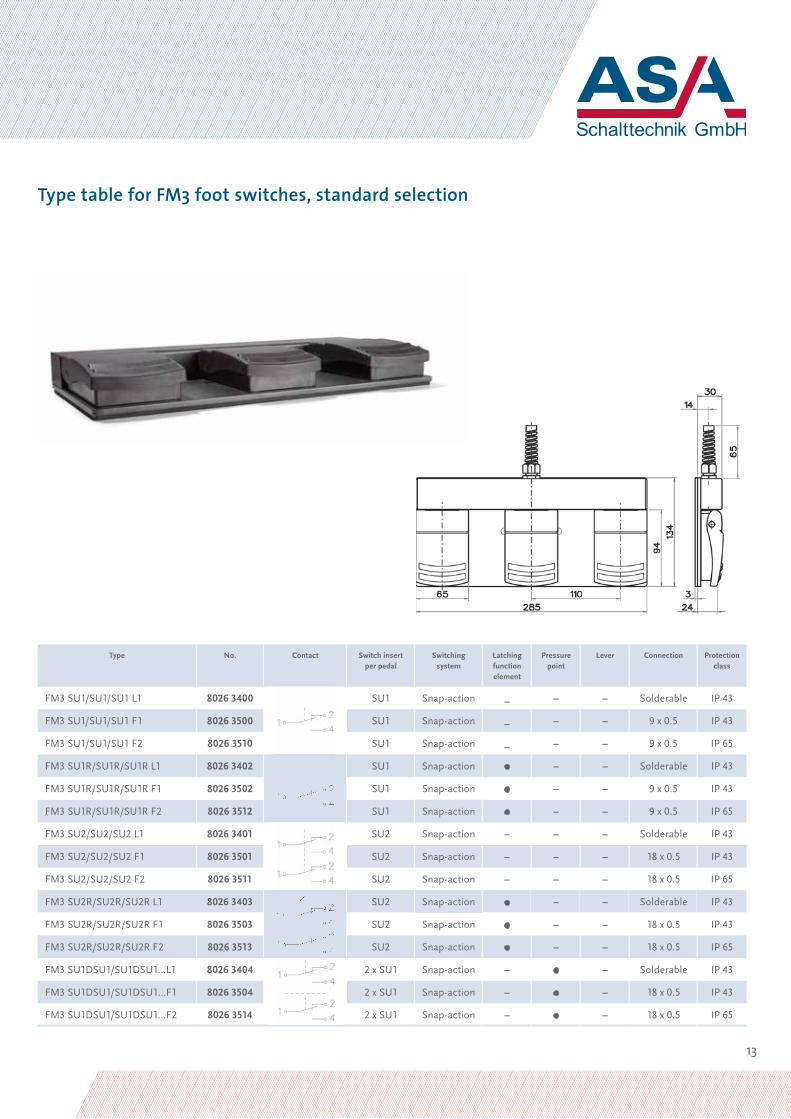
FM3 SU1/SU1/SU1 L1 8026 3400 SU1 Snap-action _ – – Solderable IP 43
FM3 SU1/SU1/SU1 F1 8026 3500 SU1 Snap-action _ – – 9 x 0.5 IP 43
FM3 SU1/SU1/SU1 F2 8026 3510 SU1 Snap-action _ – – 9 x 0.5 IP 65
FM3 SU1R/SU1R/SU1R L1 8026 3402 SU1 Snap-action • – – Solderable IP 43
FM3 SU1R/SU1R/SU1R F1 8026 3502 SU1 Snap-action • – – 9 x 0.5 IP 43
FM3 SU1R/SU1R/SU1R F2 8026 3512 SU1 Snap-action • – – 9 x 0.5 IP 65
FM3 SU2/SU2/SU2 L1 8026 3401 SU2 Snap-action – – – Solderable IP 43
FM3 SU2/SU2/SU2 F1 8026 3501 SU2 Snap-action – – – 18 x 0.5 IP 43
FM3 SU2/SU2/SU2 F2 8026 3511 SU2 Snap-action – – – 18 x 0.5 IP 65
FM3 SU2R/SU2R/SU2R L1 8026 3403 SU2 Snap-action • – – Solderable IP 43
FM3 SU2R/SU2R/SU2R F1 8026 3503 SU2 Snap-action • – – 18 x 0.5 IP 43
FM3 SU2R/SU2R/SU2R F2 8026 3513 SU2 Snap-action • – – 18 x 0.5 IP 65
FM3 SU1DSU1/SU1DSU1…L1 8026 3404 2 x SU1 Snap-action – • – Solderable IP 43
FM3 SU1DSU1/SU1DSU1…F1 8026 3504 2 x SU1 Snap-action – • – 18 x 0.5 IP 43
FM3 SU1DSU1/SU1DSU1…F2 8026 3514 2 x SU1 Snap-action – • – 18 x 0.5 IP 65
Type table for FM3 foot switches, standard selection

14
TYPE FK foot switch, small design
Number of pedals 1 1 Pedal
Switch insert SU1 Snap-action switch, 1 changeover contact
SU2 Snap-action switches, 2 changeover contacts
Connection L Solderable, unwired
K Can be clamped
F Permanently connected supply cable
Foot switches in the FK line ASA foot switches in the FK line are small plastic foot switches. They are especially used in small machine and equipment engineering and also in medical applications. They are characterised by their compact design in combination with bigger, but still very flat operating pedals. The ergonomically designed housing can be fitted with one or two switch inserts – flexibility that makes it particularly attractive for many different applications. The pedal can be operated as a single switch or in two steps with a pressure point. Protection class IP 65 according to IEC/EN 60529. Note: FK foot switches are also available with three switch inserts and a foot guard – we’ll be happy to advise you.
Type key for FK line, standard designs
Additional pedal function D Pressure point
Foot guard U Foot guard
Example: FK1 SU1 F U
FK foot switches

15
Technical specifications for foot switches in the FK line
Regulations: ASA foot-operated switches are manufactured in accordance with the applicable regulations IEC/EN 60204 and IEC/EN 60947-5-1.
Design: 1-pedal plastic foot switch, small design, free-standing on non-slip elastic feet or fixed by screws from below.
Housing: Thermoplastic ABS-black grey. More colours on request.
Pedal: Thermoplastic ABS-black grey. More colours on request.
Foot guard: Sheet steel, powder-coated-red RAL 3000. More colours on request.
Connection: • Solderable, unwired • Can be clamped • PVC control cable, structure corresponds to H05VV-F, S = 0.75 mm², black, length 2 mm
Cable inlet: 1 or 2 protective rubber sleeves
Protection class: IP 43 according to IEC/EN 60529
Switching contact: 1-2 changeover contacts, simultaneous switching or sequence control. Also available as a special design with 3 changeover contacts.
Switching function: • Momentary • Sequence circuit with pressure point
Switching cycles: min. 10 million
Working temperature: -20 °C to +80 °C
Switch inserts SU1 SU2
Switch type: 1 changeover contact switch with single break
2 changeover contact switch with single break
Switching system: Snap-action mechanism Snap-action mechanism
Contact material: Silver Silver
Voltage: max. 250 VAC, 40-60 Hz max. 250 VAC, 40-60 Hz
Current capacity: max. 6 A max. 6 A
Approvals: UL, CSA, VDE, SEV, SEMKO UL, CSA, VDE, SEV, SEMKO

16
Type table for FK1 foot switches, standard selection
Type No. Contact Switch insertper pedal
Switching system
Latching function element
Pressure point
Lever Connection Protection class
FK1 SU1 L 8026 0400 SU1 Snap-action _ – – Solderable IP 43
FK1 SU1 K 8026 0401 SU1 Snap-action _ – – Can be clamped IP 43
FK1 SU1 F 8026 0402 SU1 Snap-action _ – – 3 x 0.75 IP 43
FK1 SU2 L 8026 0403 SU2 Snap-action _ – – Solderable IP 43
FK1 SU2 K 8026 0404 SU2 Snap-action _ – – Can be clamped IP 43
FK1 SU2 F 8026 0405 SU2 Snap-action _ – – 6 x 0.75 IP 43
FK1 SU1DSU1 L 8026 0409 2 x SU1 Snap-action – • – Solderable IP 43
FK1 SU1DSU1 K 8026 0410 2 x SU1 Snap-action – • – Can be clamped IP 43
FK1 SU1DSU1 F 8026 0411 2 x SU1 Snap-action – • – 6 x 0.75 IP 43
FK foot switches

17
Type table for FK1...U foot switches, standard selection
Type No. Contact Switch insertper pedal
Switching system
Latching function element
Pressure point
Lever Connection Protecti-on class
FK1 SU1 L U 8026 0421 SU1 Snap-action _ – – Solderable IP 43
FK1 SU1 K U 8026 0422 SU1 Snap-action _ – – Can be clamped IP 43
FK1 SU1 F U 8026 0423 SU1 Snap-action _ – – 3 x 0.75 IP 43
FK1 SU2 L U 8026 0424 SU2 Snap-action _ – – Solderable IP 43
FK1 SU2 K U 8026 0425 SU2 Snap-action _ – – Can be clamped IP 43
FK1 SU2 F U 8026 0426 SU2 Snap-action _ – – 6 x 0.75 IP 43
FK1 SU1DSU1 L U 8026 0429 2 x SU1 Snap-action – • – Solderable IP 43
FK1 SU1DSU1 K U 8026 0430 2 x SU1 Snap-action – • – Can be clamped IP 43
FK1 SU1DSU1 F U 8026 0431 2 x SU1 Snap-action – • – 6 x 0.75 IP 43
18
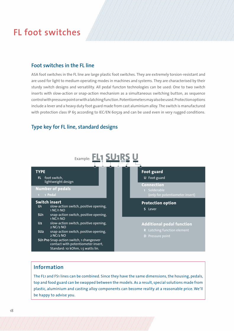
TYPE FL foot switch, lightweight design
Number of pedals 1 1 Pedal
Switch insert U1 slow-action switch, positive opening, 1 NC/1 NO SU1 snap-action switch, positive opening, 1 NC/1 NO U2 slow-action switch, positive opening, 2 NC/2 NO SU2 snap-action switch, positive opening, 2 NC/2 NO SU1 P10 Snap-action switch, 1 changeover contact with potentiometer insert, Standard: 10 kOhm, 1.5 watts lin.
Protection option S Lever
Example: FL1 SU1RS U
Foot switches in the FL line ASA foot switches in the FL line are large plastic foot switches. They are extremely torsion-resistant and are used for light to medium operating modes in machines and systems. They are characterised by their sturdy switch designs and versatility. All pedal functon technologies can be used: One to two switch inserts with slow-action or snap-action mechanism as a simultaneous switching button, as sequence control with pressure point or with a latching function. Potentiometers may also be used. Protection options include a lever and a heavy duty foot guard made from cast aluminium alloy. The switch is manufactured with protection class IP 65 according to IEC/EN 60529 and can be used even in very rugged conditions.
Type key for FL line, standard designs
Additional pedal function R Latching function element
D Pressure point
Connection 1 Solderable (only for potentiometer insert)
Foot guard U Foot guard
Information The FL1 and FS1 lines can be combined. Since they have the same dimensions, the housing, pedals, top and food guard can be swapped between the models. As a result, special solutions made from plastic, aluminium and casting alloy components can become reality at a reasonable price. We’ll be happy to advise you.
FL foot switches
19
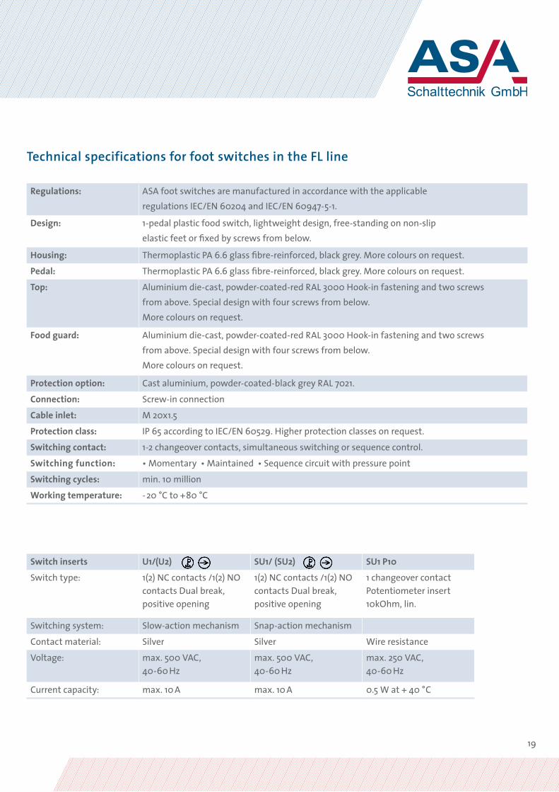
Technical specifications for foot switches in the FL line
Regulations: ASA foot switches are manufactured in accordance with the applicable regulations IEC/EN 60204 and IEC/EN 60947-5-1.
Design: 1-pedal plastic food switch, lightweight design, free-standing on non-slip elastic feet or fixed by screws from below.
Housing: Thermoplastic PA 6.6 glass fibre-reinforced, black grey. More colours on request.
Pedal: Thermoplastic PA 6.6 glass fibre-reinforced, black grey. More colours on request.
Top: Aluminium die-cast, powder-coated-red RAL 3000 Hook-in fastening and two screws from above. Special design with four screws from below.More colours on request.
Food guard: Aluminium die-cast, powder-coated-red RAL 3000 Hook-in fastening and two screws from above. Special design with four screws from below.More colours on request.
Protection option: Cast aluminium, powder-coated-black grey RAL 7021.
Connection: Screw-in connection
Cable inlet: M 20x1.5
Protection class: IP 65 according to IEC/EN 60529. Higher protection classes on request.
Switching contact: 1-2 changeover contacts, simultaneous switching or sequence control.
Switching function: • Momentary • Maintained • Sequence circuit with pressure point
Switching cycles: min. 10 million
Working temperature: -20 °C to +80 °C
Switch inserts U1/(U2) SU1/ (SU2) SU1 P10
Switch type: 1(2) NC contacts /1(2) NO contacts Dual break, positive opening
1(2) NC contacts /1(2) NO contacts Dual break, positive opening
1 changeover contact Potentiometer insert 10kOhm, lin.
Switching system: Slow-action mechanism Snap-action mechanism
Contact material: Silver Silver Wire resistance
Voltage: max. 500 VAC, 40-60 Hz
max. 500 VAC, 40-60 Hz
max. 250 VAC, 40-60 Hz
Current capacity: max. 10 A max. 10 A 0.5 W at + 40 °C

20
Type table for FL1 foot switches, standard selection
Type No. Contact Switch insertper pedal
Switching system
Latching function element
Pressure point
Lever Connection Protection class
FL1 U1 8026 0500 U1 Slow-action _ – – Can be clamped IP 65
FL1 U1S 8026 0502 U1 Slow-action _ – • Can be clamped IP 65
FL1 U1R 8026 0501 U1 Slow-action • – – Can be clamped IP 65
FL1 U1RS 8026 0503 U1 Slow-action • – • Can be clamped IP 65
FL1 SU1 8026 0520 SU1 Snap-action _ – – Can be clamped IP 65
FL1 SU1S 8026 0522 SU1 Snap-action _ – • Can be clamped IP 65
FL1 SU1R 8026 0521 SU1 Snap-action • – – Can be clamped IP 65
FL1 SU1RS 8026 0523 SU1 Snap-action • – • Can be clamped IP 65
FL1 U2 8026 0540 U2 Slow-action – – – Can be clamped IP 65
FL1 U2S 8026 0542 U2 Slow-action – – • Can be clamped IP 65
FL1 U1DU1 8026 0541 2 x U1 Slow-action – • – Can be clamped IP 65
FL1 U1DU1S 8026 0543 2 x U1 Slow-action – • • Can be clamped IP 65
FL1 SU2 8026 0560 SU2 Snap-action – – – Can be clamped IP 65
FL1 SU2S 8026 0562 SU2 Snap-action – – • Can be clamped IP 65
FL1 SU1DSU1 8026 0561 2 x SU1 Snap-action – • – Can be clamped IP 65
FL1 SU1DSU1S 8026 0563 2 x SU1 Snap-action – • • Can be clamped IP 65
FL1 SU1 P10 L 8026 0570 SU1 P10 Snap-action – – – Solderable IP 65
FL foot switches

21
Type No. Contact Switch insertper pedal
Switching system
Latching function element
Pressure point
Lever Connection Protection class
FL1 U1 U 8026 4000 U1 Slow-action _ – – Can be clamped IP 65
FL1 U1S U 8026 4001 U1 Slow-action _ – • Can be clamped IP 65
FL1 U1R U 8026 4002 U1 Slow-action • – – Can be clamped IP 65
FL1 U1RS U 8026 4003 U1 Slow-action • – • Can be clamped IP 65
FL1 SU1 U 8026 4020 SU1 Snap-action _ – – Can be clamped IP 65
FL1 SU1S U 8026 4022 SU1 Snap-action _ – • Can be clamped IP 65
FL1 SU1R U 8026 4021 SU1 Snap-action • – – Can be clamped IP 65
FL1 SU1RS U 8026 4023 SU1 Snap-action • – • Can be clamped IP 65
FL1 U2 U 8026 4040 U2 Slow-action – – – Can be clamped IP 65
FL1 U2S U 8026 4042 U2 Slow-action – – • Can be clamped IP 65
FL1 U1DU1 U 8026 4041 2 x U1 Slow-action – • – Can be clamped IP 65
FL1 U1DU1S U 8026 4043 2 x U1 Slow-action – • • Can be clamped IP 65
FL1 SU2 U 8026 4060 SU2 Snap-action – – – Can be clamped IP 65
FL1 SU2S U 8026 4062 SU2 Snap-action – – • Can be clamped IP 65
FL1 SU1DSU1 U 8026 4061 2 x SU1 Snap-action – • – Can be clamped IP 65
FL1 SU1DSU1S U 8026 4063 2 x SU1 Snap-action – • • Can be clamped IP 65
FL1 SU1 P10 L U 8026 4070 SU1 P10 Snap-action – – – Solderable IP 65
Type table for FL1...U foot switches, standard selection

22
TYPE FS foot switch, heavy design
Number of pedals 1 1 Pedal 2 2 Pedals 3 3 Pedals
Switch insert U1 slow-action switch, positive opening, 1 NC/1 NO SU1 snap-action switch, positive opening, 1 NC/1 NO U2 slow-action switch, positive opening, 2 NC/2 NO SU2 snap-action switch, positive opening, 2 NC/2 NO SU1 P10 Snap-action switch, 1 changeover contact with potentiometer insert, standard: 10 kOhm, 1.5 watts lin.
Protection option S Lever
V Lock
Example: FS1 SU1RS U
Foot switches in the FS lineASA foot switches in the FS line are large foot switches which, due to their extremely sturdy cast aluminium alloy, are ideal for use in the heavy manufacturing, mechanical engineering and plant construction industries as well as in the medical sector. The foot switches are sturdy, compact and extremely versatile. One to two switch inserts can be used with slow-action or snap- action mechanism as a simultaneous switching button, as sequence control with pressure point or with a latching func-tion. Potentiometers can also be used. For additional protection, a lever, cast aluminium alloy foot guard and a pedal lock are available on request. The products are also manufactured in protection class IP 65 according to IEC/EN 60529.
Type key for FS line, standard designs
Additional pedal function R Latching function element
D Pressure point
Foot guard U Foot guard
InformationThe FL1 and FS1 lines can be combined. Since they have the same dimensions, the housing, pedals, top and food guard can be swapped between the models. As a result, special solutions made from plastic, aluminium and casting alloy components can become reality at a reasonable price. We’ll be happy to advise you.
Connection 1 Solderable (only for potentiometer insert)
FS foot switches
23
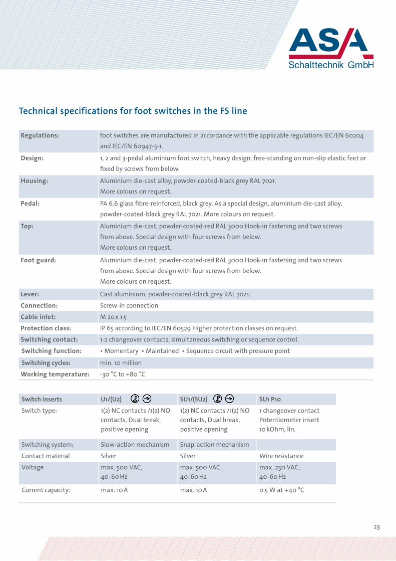
Technical specifications for foot switches in the FS line
Regulations: foot switches are manufactured in accordance with the applicable regulations IEC/EN 60204 and IEC/EN 60947-5-1.
Design: 1, 2 and 3-pedal aluminium foot switch, heavy design, free-standing on non-slip elastic feet or fixed by screws from below.
Housing: Aluminium die-cast alloy, powder-coated-black grey RAL 7021.More colours on request.
Pedal: PA 6.6 glass fibre-reinforced, black grey. As a special design, aluminium die-cast alloy, powder-coated-black grey RAL 7021. More colours on request.
Top: Aluminium die-cast, powder-coated-red RAL 3000 Hook-in fastening and two screws from above. Special design with four screws from below.More colours on request.
Foot guard: Aluminium die-cast, powder-coated-red RAL 3000 Hook-in fastening and two screws from above. Special design with four screws from below.More colours on request.
Lever: Cast aluminium, powder-coated-black grey RAL 7021.
Connection: Screw-in connection
Cable inlet: M 20x 1.5
Protection class: IP 65 according to IEC/EN 60529 Higher protection classes on request.
Switching contact: 1-2 changeover contacts, simultaneous switching or sequence control.
Switching function: • Momentary • Maintained • Sequence circuit with pressure point
Switching cycles: min. 10 million
Working temperature: -30 °C to +80 °C
Switch inserts U1/(U2) SU1/(SU2) SU1 P10
Switch type: 1(2) NC contacts /1(2) NO contacts, Dual break, positive opening
1(2) NC contacts /1(2) NO contacts, Dual break, positive opening
1 changeover contact Potentiometer insert 10 kOhm, lin.
Switching system: Slow-action mechanism Snap-action mechanism
Contact material Silver Silver Wire resistance
Voltage max. 500 VAC, 40-60 Hz
max. 500 VAC, 40-60 Hz
max. 250 VAC,40-60 Hz
Current capacity: max. 10 A max. 10 A 0.5 W at +40 °C

24
Type table for FS1 foot switches, standard selection
Type No. Contact Switch insertper pedal
Switching system
Latching function element
Pressure point
Lever Connection Protection class
FS1 U1 8026 0600 U1 Slow-action _ – – Can be clamped IP 65
FS1 U1S 8026 0602 U1 Slow-action _ – • Can be clamped IP 65
FS1 U1R 8026 0601 U1 Slow-action • – – Can be clamped IP 65
FS1 U1RS 8026 0603 U1 Slow-action • – • Can be clamped IP 65
FS1 SU1 8026 0620 SU1 Snap-action _ – – Can be clamped IP 65
FS1 SU1S 8026 0622 SU1 Snap-action _ – • Can be clamped IP 65
FS1 SU1R 8026 0621 SU1 Snap-action • – – Can be clamped IP 65
FS1 SU1RS 8026 0623 SU1 Snap-action • – • Can be clamped IP 65
FS1 U2 8026 0640 U2 Slow-action – – – Can be clamped IP 65
FS1 U2S 8026 0642 U2 Slow-action – – • Can be clamped IP 65
FS1 U1DU1 8026 0641 2 x U1 Slow-action – • – Can be clamped IP 65
FS1 U1DU1S 8026 0643 2 x U1 Slow-action – • • Can be clamped IP 65
FS1 SU2 8026 0660 SU2 Snap-action – – – Can be clamped IP 65
FS1 SU2S 8026 0662 SU2 Snap-action – – • Can be clamped IP 65
FS1 SU1DSU1 8026 0661 2 x SU1 Snap-action – • – Can be clamped IP 65
FS1 SU1DSU1S 8026 0663 2 x SU1 Snap-action – • • Can be clamped IP 65
FS1 SU1 P10 L 8026 0670 SU1 P10 Snap-action – – – Solderable IP 65
FS foot switches

25
Type No. Contact Switch insertper pedal
Switching system
Latching function element
Pressure point
Lever Connection Protection class
FS1 U1 U 8026 0680 U1 Slow-action _ – – Can be clamped IP 65
FS1 U1S U 8026 0682 U1 Slow-action _ – • Can be clamped IP 65
FS1 U1R U 8026 0681 U1 Slow-action • – – Can be clamped IP 65
FS1 U1RS U 8026 0683 U1 Slow-action • – • Can be clamped IP 65
FS1 SU1 U 8026 0720 SU1 Snap-action _ – – Can be clamped IP 65
FS1 SU1S U 8026 0722 SU1 Snap-action _ – • Can be clamped IP 65
FS1 SU1R U 8026 0721 SU1 Snap-action • – – Can be clamped IP 65
FS1 SU1RS U 8026 0723 SU1 Snap-action • – • Can be clamped IP 65
FS1 U2 U 8026 0760 U2 Slow-action – – – Can be clamped IP 65
FS1 U2S U 8026 0762 U2 Slow-action – – • Can be clamped IP 65
FS1 U1DU1 U 8026 0761 2 x U1 Slow-action – • – Can be clamped IP 65
FS1 U1DU1S U 8026 0763 2 x U1 Slow-action – • • Can be clamped IP 65
FS1 SU2 U 8026 0765 SU2 Snap-action – – – Can be clamped IP 65
FS1 SU2S U 8026 0767 SU2 Snap-action – – • Can be clamped IP 65
FS1 SU1DSU1 U 8026 0766 2 x SU1 Snap-action – • – Can be clamped IP 65
FS1 SU1DSU1S U 8026 0768 2 x SU1 Snap-action – • • Can be clamped IP 65
FS1 SU1 P10 L U 8026 0770 SU1 P10 Snap-action – – – Solderable IP 65
Type table for FS1...U foot switches, standard selection

26
Type table for FS2 foot switches, standard selection
Type No. Contact Switch insertper pedal
Switching system
Latching function element
Pressure point
Lever Connection Protection class
FS2 U1/U1 8026 0800 U1 Slow-action _ – – Can be clamped IP 65
FS2 U1S/U1S 8026 0802 U1 Slow-action _ – • Can be clamped IP 65
FS2 U1R/U1R 8026 0801 U1 Slow-action • – – Can be clamped IP 65
FS2 U1RS/U1RS 8026 0803 U1 Slow-action • – • Can be clamped IP 65
FS2 SU1/SU1 8026 0820 SU1 Snap-action _ – – Can be clamped IP 65
F2 SU1S/SU1S 8026 0822 SU1 Snap-action _ – • Can be clamped IP 65
FS2 SU1R/SU1R 8026 0821 SU1 Snap-action • – – Can be clamped IP 65
FS2 SU1RS/SU1RS 8026 0823 SU1 Snap-action • – • Can be clamped IP 65
FS2 U2/U2 8026 0840 U2 Slow-action – – – Can be clamped IP 65
FS2 U2S/U2S 8026 0842 U2 Slow-action – – • Can be clamped IP 65
FS2 U1DU1/U1DU1 8026 0841 2 x U1 Slow-action – • – Can be clamped IP 65
FS2 U1DU1S/U1DU1S 8026 0843 2 x U1 Slow-action – • • Can be clamped IP 65
FS2 SU2/SU2 8026 0860 SU2 Snap-action – – – Can be clamped IP 65
FS2 SU2S/SU2S 8026 0862 SU2 Snap-action – – • Can be clamped IP 65
FS2 SU1DSU1/SU1DSU1 8026 0861 2 x SU1 Snap-action – • – Can be clamped IP 65
FS2 SU1DSU1S/SU1DSU1S 8026 0863 2 x SU1 Snap-action – • • Can be clamped IP 65
FS foot switches
27
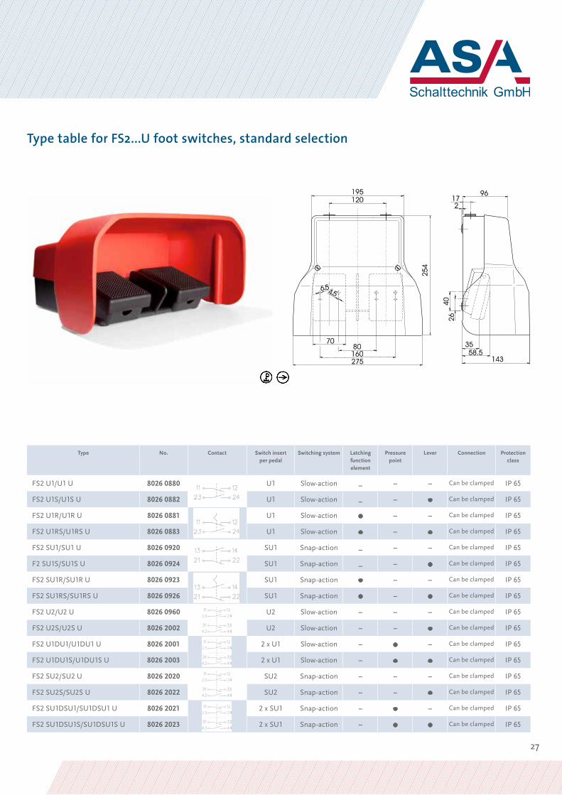
Type table for FS2...U foot switches, standard selection
Type No. Contact Switch insertper pedal
Switching system Latching function element
Pressure point
Lever Connection Protection class
FS2 U1/U1 U 8026 0880 U1 Slow-action _ – – Can be clamped IP 65
FS2 U1S/U1S U 8026 0882 U1 Slow-action _ – • Can be clamped IP 65
FS2 U1R/U1R U 8026 0881 U1 Slow-action • – – Can be clamped IP 65
FS2 U1RS/U1RS U 8026 0883 U1 Slow-action • – • Can be clamped IP 65
FS2 SU1/SU1 U 8026 0920 SU1 Snap-action _ – – Can be clamped IP 65
F2 SU1S/SU1S U 8026 0924 SU1 Snap-action _ – • Can be clamped IP 65
FS2 SU1R/SU1R U 8026 0923 SU1 Snap-action • – – Can be clamped IP 65
FS2 SU1RS/SU1RS U 8026 0926 SU1 Snap-action • – • Can be clamped IP 65
FS2 U2/U2 U 8026 0960 U2 Slow-action – – – Can be clamped IP 65
FS2 U2S/U2S U 8026 2002 U2 Slow-action – – • Can be clamped IP 65
FS2 U1DU1/U1DU1 U 8026 2001 2 x U1 Slow-action – • – Can be clamped IP 65
FS2 U1DU1S/U1DU1S U 8026 2003 2 x U1 Slow-action – • • Can be clamped IP 65
FS2 SU2/SU2 U 8026 2020 SU2 Snap-action – – – Can be clamped IP 65
FS2 SU2S/SU2S U 8026 2022 SU2 Snap-action – – • Can be clamped IP 65
FS2 SU1DSU1/SU1DSU1 U 8026 2021 2 x SU1 Snap-action – • – Can be clamped IP 65
FS2 SU1DSU1S/SU1DSU1S U 8026 2023 2 x SU1 Snap-action – • • Can be clamped IP 65
28
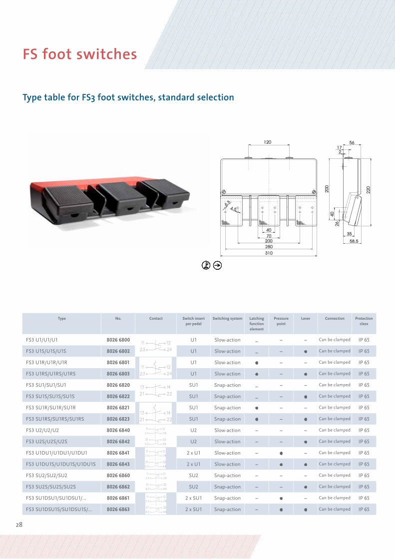
Type table for FS3 foot switches, standard selection
Type No. Contact Switch insertper pedal
Switching system Latching function element
Pressure point
Lever Connection Protection class
FS3 U1/U1/U1 8026 6800 U1 Slow-action _ – – Can be clamped IP 65
FS3 U1S/U1S/U1S 8026 6802 U1 Slow-action _ – • Can be clamped IP 65
FS3 U1R/U1R/U1R 8026 6801 U1 Slow-action • – – Can be clamped IP 65
FS3 U1RS/U1RS/U1RS 8026 6803 U1 Slow-action • – • Can be clamped IP 65
FS3 SU1/SU1/SU1 8026 6820 SU1 Snap-action _ – – Can be clamped IP 65
FS3 SU1S/SU1S/SU1S 8026 6822 SU1 Snap-action _ – • Can be clamped IP 65
FS3 SU1R/SU1R/SU1R 8026 6821 SU1 Snap-action • – – Can be clamped IP 65
FS3 SU1RS/SU1RS/SU1RS 8026 6823 SU1 Snap-action • – • Can be clamped IP 65
FS3 U2/U2/U2 8026 6840 U2 Slow-action – – – Can be clamped IP 65
FS3 U2S/U2S/U2S 8026 6842 U2 Slow-action – – • Can be clamped IP 65
FS3 U1DU1/U1DU1/U1DU1 8026 6841 2 x U1 Slow-action – • – Can be clamped IP 65
FS3 U1DU1S/U1DU1S/U1DU1S 8026 6843 2 x U1 Slow-action – • • Can be clamped IP 65
FS3 SU2/SU2/SU2 8026 6860 SU2 Snap-action – – – Can be clamped IP 65
FS3 SU2S/SU2S/SU2S 8026 6862 SU2 Snap-action – – • Can be clamped IP 65
FS3 SU1DSU1/SU1DSU1/… 8026 6861 2 x SU1 Snap-action – • – Can be clamped IP 65
FS3 SU1DSU1S/SU1DSU1S/… 8026 6863 2 x SU1 Snap-action – • • Can be clamped IP 65
FS foot switches

29
Type table for FS3...U foot switches, standard selection
Type No. Contact Switch insertper pedal
Switching system
Latching function element
Pressure point
Lever Connection Protecti-on class
FS3 U1/U1/U1 U 8026 6880 U1 Slow-action _ – – Can be clamped IP 65
FS3 U1S/U1S/U1S U 8026 6882 U1 Slow-action _ – • Can be clamped IP 65
FS3 U1R/U1R/U1R U 8026 6881 U1 Slow-action • – – Can be clamped IP 65
FS3 U1RS/U1RS/U1RS U 8026 6883 U1 Slow-action • – • Can be clamped IP 65
FS3 SU1/SU1/SU1 U 8026 6920 SU1 Snap-action _ – – Can be clamped IP 65
FS3 SU1S/SU1S/SU1S U 8026 6924 SU1 Snap-action _ – • Can be clamped IP 65
FS3 SU1R/SU1R/SU1R U 8026 6923 SU1 Snap-action • – – Can be clamped IP 65
FS3 SU1RS/SU1RS/SU1RS U 8026 6926 SU1 Snap-action • – • Can be clamped IP 65
FS3 U2/U2/U2 U 8026 6960 U2 Slow-action – – – Can be clamped IP 65
FS3 U2S/U2S/U2S U 8026 8002 U2 Slow-action – – • Can be clamped IP 65
FS3 U1DU1/U1DU1/U1DU1 U 8026 8001 2 x U1 Slow-action – • – Can be clamped IP 65
FS3 U1DU1S/U1DU1S/U1DU1S U 8026 8003 2 x U1 Slow-action – • • Can be clamped IP 65
FS3 SU2/SU2/SU2 U 8026 8020 SU2 Snap-action – – – Can be clamped IP 65
FS3 SU2S/SU2S/SU2S U 8026 8022 SU2 Snap-action – – • Can be clamped IP 65
FS3 SU1DSU1/SU1DSU1/… U 8026 8021 2 x SU1 Snap-action – • – Can be clamped IP 65
FS3 SU1DSU1S/SU1DSU1S/… U 8026 8023 2 x SU1 Snap-action – • • Can be clamped IP 65

30
Colour? Select and request!
Our foot switches have a lot to offer and they also look great: We can customise your housings, tops and food guards in any RAL colour of your choice. Individually coloured ASA foot switches fit harmoniously into any design. Naturally, our sales team will be happy to advise you about our attractive terms and conditions.
ASA foot switches

31
Key
Colour codes according to DIN IEC 757
BK black
BN brown
BU blue
GY grey
RD red
WH white
Other signs
Positive opening travel according to GS-ET-15
Positive opening contact
0912
/700
0 03
00
Figures and technical data are not binding. We reserve the right to make changes at any time due to technical improvements.
ASA Schalttechnik GmbH F.-A.-Meyer-Straße 4 32457 Porta Westfalica Germany
Phone: +49(0)571/97530-0
Fax: +49(0)571/9753080
www.asa-schalttechnik.com [email protected]


![Planet-SWITCH Limit, micro and foot switches K series shock or vibration. • Versions with safety lever. The safety ... KGD KGR KR1 KR2 Foot switches - Dimensions [mm] Technical characteristics](https://static.fdocuments.net/doc/165x107/5b06ba4d7f8b9ac33f8d360f/planet-switch-limit-micro-and-foot-switches-k-shock-or-vibration-versions.jpg)