Font rendering on a GPU-based raster image · PDF fileFont rendering on a GPU-based raster...
15
Keyword(s): Abstract: © Font rendering on a GPU-based raster image processor John L. Recker, Giordano B. Beretta, I-Jong Lin HP Laboratories HPL-2009-181 printing, fonts, rendering, RIP, GPU Historically, in the 35 years of digital printing research, raster image processing has always lagged behind marking engine technology, i.e., we have never been able to deliver rendered digital pages as fast as digital print engines can consume them. This trend has resulted in products based on throttled digital printers or expensive raster image processors (RIP) with hardware acceleration. The current trend in computer software architecture is to leverage graphic processing units (GPU) for computing tasks whenever appropriate. We discuss the issues for rendering fonts on such an architecture and present an implementation. External Posting Date: August 6, 2009 [Fulltext] Approved for External Publication Internal Posting Date: August 6, 2009 [Fulltext] Copyright 2009 Hewlett-Packard Development Company, L.P.
Transcript of Font rendering on a GPU-based raster image · PDF fileFont rendering on a GPU-based raster...
Keyword(s): Abstract:
©
Font rendering on a GPU-based raster image processor
John L. Recker, Giordano B. Beretta, I-Jong Lin
HP LaboratoriesHPL-2009-181
printing, fonts, rendering, RIP, GPU
Historically, in the 35 years of digital printing research, raster image processing has always lagged behindmarking engine technology, i.e., we have never been able to deliver rendered digital pages as fast as digitalprint engines can consume them. This trend has resulted in products based on throttled digital printers orexpensive raster image processors (RIP) with hardware acceleration. The current trend in computersoftware architecture is to leverage graphic processing units (GPU) for computing tasks wheneverappropriate. We discuss the issues for rendering fonts on such an architecture and present animplementation.
External Posting Date: August 6, 2009 [Fulltext] Approved for External PublicationInternal Posting Date: August 6, 2009 [Fulltext]
Copyright 2009 Hewlett-Packard Development Company, L.P.
Font rendering on a GPU-based raster image processor
John L. Recker, Giordano B. Beretta, I-Jong Lin
Hewlett-Packard Laboratories, Print Production Automation Lab1501 Page Mill Road, Palo Alto, USA
ABSTRACT
Historically, in the 35 years of digital printing research, raster image processing has always lagged behind markingengine technology, i.e., we have never been able to deliver rendered digital pages as fast as digital print enginescan consume them. This trend has resulted in products based on throttled digital printers or expensive rasterimage processors (RIP) with hardware acceleration. The current trend in computer software architecture is toleverage graphic processing units (GPU) for computing tasks whenever appropriate. We discuss the issues forrendering fonts on such an architecture and present an implementation.
Keywords: printing, fonts, rendering, RIP, GPU
1. INTRODUCTION
1.1 Origins of digital printingThere have been several paths to contemporary high-speed digital printing, like for example TROFF, TEX, andPDF. The paths have been more evolutionary than revolutionary, with some like memory evolving fast and otherslike print speed evolving slowly. All paths had to contend with Wirth’s law “software is getting slower morerapidly than hardware becomes faster.” Therefore, to understand our architectural design decision, we have togive some background. Although we wrote this paper in LATEXfor its beautiful typography, in our research wehave followed the PDF path and we will limit ourselves to it.
Early high-speed digital printers were line printers. A chain with a train of multiple copies of the types foran alphabet would circulate in front of the current text line of the paper. Behind the paper there was a line ofhammers driven by solenoids. For each type position on the line, the hammer would strike the first time theintended character’s type was at that position, and the type through an ink ribbon would mark the paper. Theseprinters were very loud, expensive, and failure prone. Most of the time, the chain would contain only trainsof upper case types, because using also lower case characters would halve the printer’s speed. The printer wastypically attached to the computer via a peripheral processor, which would control the printer and stream ASCIIsequences containing the characters to be printed and formatting commands like carriage returns and line feeds.
A technological breakthrough did not happen until 1971, when Gary Starkweather1 invented the laser printer,a non-impact printing technology. His first implementation — called EARS for Ethernet, Alto, RCG (researchcharacter generator), and SLOT (scanning laser output terminal) — had a resolution of 500 dots per inch andprinted one page per second. The design goal was to obtain the same print quality as a typeset documentcopied on a xerographic copier. Printing was the first Ethernet application, and actually prompted Ethernet’sinvention.2
The most difficult technical challenge in interfacing the printer was to generate the raster image for eachpage at the printer’s rated speed of 60 ppm at 500 dpi and injecting it via a 25 MHz video signal. The availablecomputer platform was the Alto and Ron Rider, with assistance from Butler Lampson, during 1972 designedspecial purpose hardware to store the font bitmaps and generate the video signal. This character generator wasthree times the size of the Alto itself, indicating the complexity of driving a bitmap-based digital printer.
The system was called a print service and consisted of three components:
Further author information: (Send correspondence to I-J.L.)J.L.R.: E-mail: [email protected], Telephone: +1 650 236 2884G.B.B.: E-mail: [email protected], Telephone: +1 650 857 6713I-J.L.: E-mail: [email protected], Telephone: +1 650 857 4094
1
• the printing interface, which describes the sequence of pages in a document, the graphical content of eachpage, the number of copies, finishing options, etc.
• the spooler accepting print jobs and queueing them
• the imager, the software rendering the page contents into a raster image
In the papers of the time, the terminology is murky, as the interfaces between hardware and software, controland data, printing and workflow, and between the components were evolving and shifting. The most commonlyused term was printing interface, and it was the sequence of bytes streamed from a computer to a printer. Later,as technology evolved, it could refer to the character generator, the page description language, the formatter,the workflow, or any combination thereof. If we keep with these murky terms, the printer interface evolved fromPeter Deutsch’s interface for the Xerox Graphics Printer (XGP). Many researchers were involved in the manyevolutionary iterations, most notably Peter Deutsch, William Newman, Bob Sproull, Butler Lampson, JohnWarnock, Dan Swinehart, Patrick Baudelaire, Bob Ayers, Ed Taft, and many more.1
As the printing interface became more formal, it was renamed page description language (PDL) and hasculminated in today’s PDF Print Engine.3 The system of hardware and software is now called raster imageprocessor (RIP).
The RIP for EARS was very expensive, and as demand for laser printers increased, there was a strongpressure to invent lower cost RIPs. As the Dorado replaced the Alto and Dandelion, more of the rendering couldbe moved from integrated circuits to software. The subsequently designed Dragon was a multi-processor machinewith eight of what we today call cores.
With time, documents increased in complexity and printers became faster, so the design of RIPs has alwaysbeen a catch-up game, with product managers pressuring for lower-cost software solutions while the reality ofnew printers demanded hardware acceleration. This acceleration is typically provided in the form of ASICs andFPGAs. One of the authors remembers his young years as a Burroughs systems representative accompanying asalesman to the ETH data center to sell them a rebranded 97004 laser printer. The customer quickly calculatedthe bandwidth required for the imager and realized it would completely eat up one of the CDC Cyber super-computers in his cluster — the sale fell though.
After two decades of reliance on Moore’s law, today we are at a new juncture. As processors are no longerbecoming faster in terms of a higher clock frequency, computer architects have learned to make better use ofall the hardware resources in a computer. In particular, even the smallest systems have multiple cores, and allsystems have GPUs. Moreover, recently the GPUs have become programmable, so they can be used as fast arrayprocessors. We have transitioned from custom hardware, to speculating on faster CPUs, to better exploiting acomplex non-uniform computer architecture.
In this paper we describe how we have build a low-cost RIP using these new architectural paradigms. Butfirst, we have to clarify the font terminology, because many documents are text oriented and the rendering oftext is the new bottleneck, not the printing of color images as it used to be in he past.
1.2 What is in a font
Let us first establish the relevant terminology. A character is an abstract symbol, like for example the lower caseletter ‘a’. In the early days of digital high-speed printers, when only upper case letters were used, a characterwas encoded as a 6 bit quantity, with typically 10 characters packed in a 60 bit word. Later, to encode upperand lower case letters, some common symbols, punctuation, and control commands, the 8 bit byte or octet wasgenerally used to encode a character. Today, characters are encoded in one or two bytes.
A character can have multiple graphical renderings like shown in Fig. 1, the second ’a’ is an alternate renderingand the second number is rendered in oldstyle. The graphical rendering of a character is called glyph. Both ‘a’glyphs in the figure have the same design, as do the numbers.
This design is called a typeface and its name is usually a registered trademark. To avoid paying licensingfees, often a design is sold under a phantasy name. Examples of typefaces are Helvetica, Times Roman, Futura,Frutiger, etc. The typeface used in Fig. 1 is called Warnock.
2
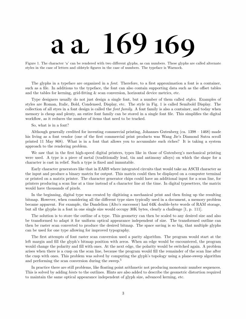
a a 169 Figure 1. The character ‘a’ can be rendered with two different glyphs, as can numbers. These glyphs are called alternatestyles in the case of letters and oldstyle figures in the case of numbers. The typeface is Warnock.
The glyphs in a typeface are organized in a font. Therefore, to a first approximation a font is a container,such as a file. In additions to the typeface, the font can also contain supporting data such as the offset tablesand the tables for kerning, grid-fitting & scan conversion, horizontal device metrics, etc.
Type designers usually do not just design a single font, but a number of them called styles. Examples ofstyles are Roman, Italic, Bold, Condensed, Display, etc. The style in Fig. 1 is called Semibold Display. Thecollection of all styes in a font design is called the font family. A font family is also a container, and today whenmemory is cheap and plenty, an entire font family can be stored in a single font file. This simplifies the digitalworkflow, as it reduces the number of items that need to be tracked.
So, what is in a font?
Although generally credited for inventing commercial printing, Johannes Gutenberg (ca. 1398 – 1468) madehis living as a font vendor (one of the first commercial print products was Wang Jie’s Diamond Sutra scrollprinted 11 May 868). What is in a font that allows you to accumulate such riches? It is taking a systemapproach to the rendering problem.
We saw that in the first high-speed digital printers, types like in those of Gutenberg’s mechanical printingwere used. A type is a piece of metal (traditionally lead, tin and antimony alloys) on which the shape for acharacter is cast in relief. Such a type is fixed and immutable.
Early character generators like that in EARS where integrated circuits that would take an ASCII character asthe input and produce a binary matrix for output. This matrix could then be displayed on a computer terminalor printed on a matrix printer. The character generator chips could have an additional input for a scan line, forprinters producing a scan line at a time instead of a character line at the time. In digital typesetters, the matrixwould have thousands of pixels.
In the beginning, digital type was created by digitizing a mechanical print and then fixing up the resultingbitmap. However, when considering all the different type sizes typically used in a document, a memory problembecame apparent. For example, the Dandelion (Alto’s successor) had 64K double-byte words of RAM storage,but all the glyphs in a font in one single size would occupy 30K bytes, clearly a challenge [1, p. 111].
The solution is to store the outline of a type. This geometry can then be scaled to any desired size and alsobe transformed to adapt it for uniform optical appearance independent of size. The transformed outline canthen be raster scan converted to produce the desired bitmap. The space saving is so big, that multiple glyphscan be used for one type allowing for improved typography.
The first attempts of font raster scan conversion used a parity algorithm. The program would start at theleft margin and fill the glyph’s bitmap position with zeros. When an edge would be encountered, the programwould change the polarity and fill with ones. At the next edge, the polarity would be switched again. A problemarises when there is a cusp on the scan line, because the program would fill the remainder of the scan line afterthe cusp with ones. This problem was solved by computing the glyph’s topology using a plane-sweep algorithmand performing the scan conversion during the sweep.5
In practice there are still problems, like floating point arithmetic not producing monotonic number sequences.This is solved by adding hints to the outlines. Hints are also added to describe the geometric distortion requiredto maintain the same optical appearance independent of glyph size, advanced kerning, etc.
3
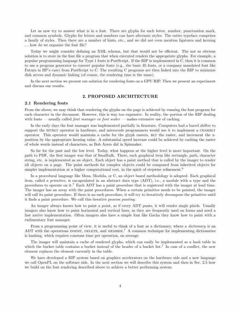
Let us now try to answer what is in a font. There are glyphs for each letter, number, punctuation mark,and common symbols. Glyphs for letters and numbers can have alternate styles. The entire typeface comprisesa family of styles. Then there are a number of hints, etc., and we did not even mention ligatures and kerning. . . how do we organize the font file?
Today we might consider defining an XML schema, but that would not be efficient. The not so obvioussolution is to store in the font file a program that when executed renders the appropriate glyphs. For example, apopular programming language for Type 1 fonts is PostScript. If the RIP is implemented in C, then it is commonto use a program generator to convert popular fonts (e.g., the basic 35 fonts, or a company mandated font likeFutura in HP’s case) from PostScript to C. The resulting C programs are then linked into the RIP to minimizedisk access and dynamic linking (of course, the rendering time is the same).
In the next section we present our solution for rendering fonts on a GPU RIP. Then we present an experimentand discuss our results.
2. PROPOSED ARCHITECTURE
2.1 Rendering fonts
From the above, we may think that rendering the glyphs on the page is achieved by running the font program foreach character in the document. However, this is way too expensive. In reality, the portion of the RIP dealingwith fonts — usually called font manager or font scaler — makes extensive use of caching.
In the early days the font manager was implemented partially in firmware. Computers had a barrel shifter tosupport the bitblt operator in hardware, and microcode programmers would use it to implement a charbltoperator. This operator would maintain a cache for the glyph rasters, blt the raster, and increment the x-position by the appropriate kerning value. A substantial speed increase could be achieved by caching the rasterof whole words instead of characters, as Bob Ayers did in Spinnaker.
So far for the past and the low level. Today, what happens at the higher level is more important. On thepath to PDF, the first imager was that of Smalltalk. There, each graphical item like rectangle, path, characterstring, etc. is implemented as an object. Each object has a paint method that is called by the imager to renderall objects on a page. The paint methods for complex objects could be composed from inherited objects forsimpler implementation at a higher computational cost, in the spirit of stepwise refinement.6
In a procedural language like Mesa, Modula, or C, an object based methodology is adopted. Each graphicalitem, called a primitive, is encapsulated in an abstract data type (ADT), i.e., a module with a type and theprocedures to operate on it.7 Each ADT has a paint procedure that is registered with the imager at load time.The imager has an array with the paint procedures. When a certain primitive needs to be painted, the imagerwill call its paint procedure. If there is no such procedure, it will try to iteratively decompose the primitive untilit finds a paint procedure. We call this iterative process punting.
An imager always knows how to paint a point, so if every ADT punts, it will render single pixels. Usuallyimagers also know how to paint horizontal and vertical lines, as they are frequently used on forms and need afast native implementation. Often imagers also have a simple font like Gacha they know how to paint with arudimentary font manager.
From a programming point of view, it is useful to think of a font as a dictionary, where a dictionary is anADT with the operations insert, delete, and member.7 A common technique for implementing dictionariesis hashing, which requires constant time per operation, on average.
The imager will maintain a cache of rendered glyphs, which can easily be implemented as a hash table inwhich the bucket table contains a bucket instead of the header of a bucket list.7 In case of a conflict, the newelement replaces the element currently in the table.
We have developed a RIP system based on graphics accelerators on the hardware side and a new languagewe call OpenPL on the software side. In the next section we will describe this system and then in Sec. 2.5 howwe build on the font rendering described above to achieve a better performing system.
4

2.2 RIP-GPU integration
Graphics Processing Units (GPU) are special purpose coprocessors originally targeted at the PC gaming market.The enormous size and volume of the gaming market have driven GPU capabilities up and costs down, makingGPUs into a viable and well-supported parallel computing architecture. Today the cost of a GPU is so low, thateven handheld devices have a GPU.
The architectural design task at hand is to partition the rendering operations between CPU and GPU. To thispurpose we perform a functional decomposition of the RIP as shown in Fig. 2: language interpretation, where thelinear PDL file is turned in a complex data structure; element decomposition, where the data structure is mappedinto geometric elements in a global page space; rasterization, compositing, and flattening, where geometries areconverted into pixels; color conversion, where pixel colors are converted into ink amounts; planarization, where inkamounts are re-arranged from a packed to a planar pixel format; and finally compression to minimize bandwidthrequirements when transmitting the RIP output to the high-speed digital printer.
PDL interpreter
element decomposer
rasterizer, composer, flattener
color manager planarizer compressor
Figure 2. Functional decomposition of a RIP.
Can we implement the whole RIP on the GPU? PDL interpretation is generally poorly suited to a data-stream parallel architecture — it is inherently a sequential process, and the code typically rife with conditionals,and is thus not considered a candidate for porting to the GPU. The next step is more challenging: selecting theelements to be accelerated natively on the GPU. PDF and Postscript, the dominant PDL print languages areboth large, sophisticated languages which offer a variety of primitives including, for example, paths — regionsbounded by arbitrary combinations of curves and segments.
Before proceeding with the operations that can potentially run on the GPU, we have to discuss how tointerface the sequential CPU cores to the massively parallel GPU. The standard method in computer graphicsis to use a display list. We have implemented a small “C” language API called OpenPL. OpenPL implementsinterfaces only for the tasks we envision as candidates for GPU acceleration: the rendering primitives and pipelinestages selected above. OpenPL uses OpenGL for primitive rendering, and we have written both Cg8 and GLSL9
routines to implement the RIP pipeline stages.
Like we leverage on OpenGL for OpenPL, we leverage on existing software for the RIP proper. SeveralPDF RIP software development kits (SDK) are available, for example Adobe’s PDF Print Engine3 and Apple’sQuartz.10 For our experiments we have used the Ghostscript11 SDK, specifically version 8. We have added ourcode as a printer driver and in the following we explain how we have integrated the GPU.
Using the Ghostscript SDK we have implemented an OpenPL driver, which contains the paint proceduresfor the primitives we want to render on the GPU. Some choices are straightforward, like rectangles and images,which can easily be rendered on the GPU. Which is the best locus for the font scaler? As we saw in Sec. 1.2, therasterization of a glyph outline is accomplished with plane-sweep type algorithms. These perform neighborhoodoperations based on topology and are therefore not well suited for a GPU.
Fortunately, the work-around is very easy. It is sufficient to punt on the paint procedure for characters butprovide a paint procedure for glyph bitmaps, and Ghostscript will then perform the font scaling calling thisbitmap paint procedure for each character.
When we designed OpenPL, we decided not to implement an operator for binary bitmaps, for the performancereasons we will explain in Sec. 2.5. Yet, creating a display list entry for every pixel for every glyph on a textpage would create a huge display list that would introduce a high cost to transfer from the CPU to the GPU.We settled for a compromise where we convert each glyph’s bitmap into a list of monochromatic horizontal linesegments. These line segments are then written to the display list. Since the mono lines are independent, theyare suitable for rendering on the GPU.
5

2.3 RIP analysis
Rather than attempt to accelerate the full spectrum of possible primitives, we have adopted an iterative, bottom-up punting approach for this project: select and accelerate the “lowest denominator” primitives as evidencedfrom workload analysis, measure the performance gain, and move up the complexity chain implementing paintprocedures, until we have achieved a balanced solution: a system that fully utilizes the computational resources(CPU, GPU and data bandwidth) available in the system. This has helped us in our decision on how to renderglyphs.
This bottom-up approach is supported by our workload analysis performed on a CPU. Analysis — as shownin Fig. 3 — of pages from a broad range of marketing collateral show that a few low level primitives: solidrectangles rect, monochromatic horizontal lines mono, image placement image dominate the time required by aCPU based RIP. Here we have punted on the other primitives, and in the case of glyphs, the imager decomposesthem into a series of monochromatic horizontal lines as explained in Sec. 2.2.
rect
mono
image
rect
mono
image
Figure 3. Low level primitive mixes for two pages from a large collection of marketing collateral containing many productimages. Left: Rendering time distribution. Right: Primitive count distribution. Execution is on a CPU.
Furthermore, as shown in Fig. 4, we find that the majority of the time spent within the RIP corresponds tothe high data bandwidth back end stages of the pipeline when the page is represented as pixels. We thereforetarget these stages for GPU acceleration. In other words, the front end requires sequential processing and isbest executed on CPU cores. The back end consists of pixel processing and is suitable for the massively parallelprocessing in which GPUs excel.
PDL interpreter
element decomposer
rasterizer, composer, flattener
color manager planarizer compressor
100 MB
1 MB
10 MB
1 GB
size per page
front end:526 ms/page
back end:5881 ms/page
CPU
Figure 4. Performance of a Ghostscript based CPU RIP. The lines on the top indicate the size of the representation ofthe page as it is transformed by RIP processing.
6

2.4 Architecture: OpenPL GPU/CPU Codesign
OpenPL is more than a thin wrapper around OpenGL. In addition to providing primitive acceleration, it isdesigned to address three system challenges: the overlap of CPU and GPU processing through pipelining whilemaximizing the throughput of each, the tiling of pages space due to GPU address limitations, and color man-agement and separation to color spaces with more than four channels.
OpenPL breaks the imaging sequence into three parallel tasks (see figure 5), each operating in its own threadand communicating via messages and a simple event loop. This approach maximizes overlap of CPU and GPUcomputational tasks.
PDL interpreter
element decomposer
rasterizer, composer, flattener
color manager planarizer
var. comp.
100 MB
1 MB
10 MB
1 GB
size per page
CPU
GPUfixed comp.
GPU transfer:to GPU 600 MB/s
from GPU 400 MB/s
Figure 5. For GPU acceleration, we target the high bandwidth low performing stages of the RIP where the page isrepresented as pixels. The compression stage is broken into a fixed and a variable compression stage.
The first task receives primitives through the OpenPL API from the PDL interpreter, and stores them inan internal primitive buffer. All primitives for a page are buffered prior to being passed to the rendering taskfor processing. This aspect of the architecture is atypical for most 2D renderers (window system drivers, forexample) which commonly operate in immediate mode. OpenPL uses the primitive buffer to support image tilingand color management. High end GPUs today support up to a 8K×8K pixel address space. While generallyquite generous for applications targeting a display, 60K×60K pixel images are common for signage targetingbillboards, buses or buildings. Page space is divided into tiles, and primitives are identified as covering imagetiles when entered into the primitive store using a coarse level clip.
The second task, the rendering task, performs three operations. First, it cycles through each image tilequeuing previously identified primitives from the primitive buffer for rasterizing using OpenGL. Each tile is thencolor managed, planarized and compressed. While PDF and PostScript specify input primitives in 1, 3, or 4channel color spaces, the output device color space is press and print job dependent which, in the case of theHP’s high-speed digital printers, can mean up to seven ink channels.
Color management is implemented using (ink count mod 4) × 3D LUTs. Seven ink rendering, for example,requires two 3D LUTs, and each tile requires two passes through the color management stages of the pipeline.
7
The high-speed digital printer marks each ink plane separately, so the planarization step converts chunky pixelsinto several single channel images. The GPU, not surprisingly, shines for color management and planarization.
However, if we were to transfer the page back from the GPU as 560 MB of pixel data, we would incur over 1000ms of latency. The image is therefore compressed prior to transfer back to the CPU. Compression is implementedusing a proprietary compression scheme which combines a fixed-size block coding scheme with variable-lengthencoding. Though a lossy compression scheme (mitigated by the perceptual design of the algorithm and the highoutput resolution), the block compression has the advantage of a fixed compression ratio — essential for addressgeneration in the parallel shader code. Thus only the first part of the compression is implemented on the GPU.The last operation performed by this task is an asynchronous transfer of the output pixels back to the CPU, asshown in Fig. 5.
The job of the third OpenPL task is to receive the output of the asynchronous result transfers from the GPU,perform the variable compression part of the compression algorithm and deliver the results back to the callingapplication.
2.5 Architecture: Fonts
We have now enough information to resume the discussion of the font manager we suspended in the last paragraphof Sec. 2.2. As we wrote, we decided not to implement an operator for binary bitmaps containing glyphs, forperformance reasons. In general, a glyph has a foreground and a background color.12 The obvious implementationwould be to have an OpenPL operator for a binary bitmap, then write a glyph paint procedure emitting anOpenPL command to set the background color, one for a rectangle of the glyph size, one to set the foregroundcolor, and finally one to paint the glyph’s bitmap.
It turns out that this implementation is unacceptably slow. The OpenPL routines for handling bitmaps arenot optimized for rendering glyph bitmaps and do not provide the required acceleration.
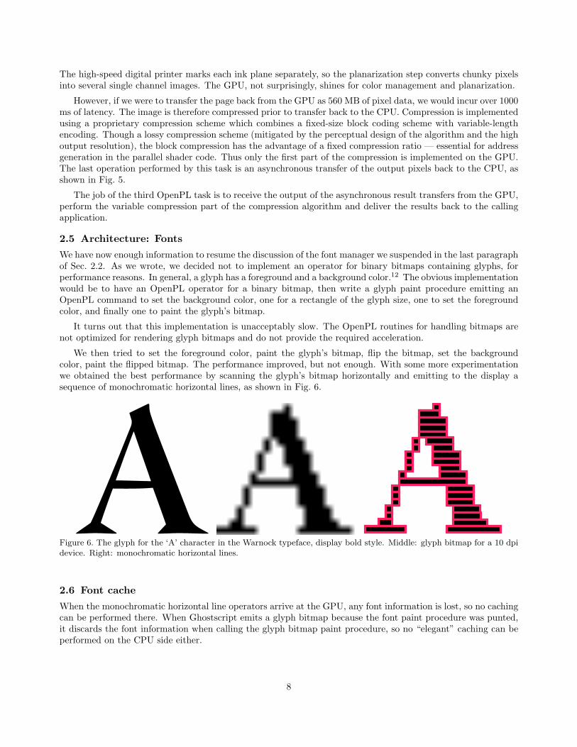
We then tried to set the foreground color, paint the glyph’s bitmap, flip the bitmap, set the backgroundcolor, paint the flipped bitmap. The performance improved, but not enough. With some more experimentationwe obtained the best performance by scanning the glyph’s bitmap horizontally and emitting to the display asequence of monochromatic horizontal lines, as shown in Fig. 6.
AFigure 6. The glyph for the ‘A’ character in the Warnock typeface, display bold style. Middle: glyph bitmap for a 10 dpidevice. Right: monochromatic horizontal lines.
2.6 Font cache
When the monochromatic horizontal line operators arrive at the GPU, any font information is lost, so no cachingcan be performed there. When Ghostscript emits a glyph bitmap because the font paint procedure was punted,it discards the font information when calling the glyph bitmap paint procedure, so no “elegant” caching can beperformed on the CPU side either.
8

We have implemented two ADTs to cache the fonts: a line list and a hash table. Instead of writing amonochromatic horizontal line operator in the display list each time we find one, we accumulate them in a linelist. When the entire glyph has been scanned, the line list is cached in the hash table.
There are several methods to implement a list. The list element is a 1 pixel high horizontal segment describedby 3 integer variables: x0, x1, and y. Allocating dynamic memory for each element as need arises would createtoo much memory management overhead, so an array is a more appropriate data structure. With that, the linelist consists of a maximum list length (the array size), and index to the next free entry, and an array of lineelements.
The question is what number to choose the array size. We could take the approach that today memory ischeap and we just allocate a big chunk. However, there is always an overhead associated with allocating memory,initializing it, and then freeing it. Moreover, the bigger the chunk, the larger the probability it can be swappedout by the memory pager. It is necessary to determine a realistic estimate of the number of line segments in aglyph.
file pages paints lists max lines max used ave. lines ave. used
4AA0-0193ENN 4 8317 510 6098 289 986 76k 9780972380133 176 277446 16020 5000 292 1580 96104973LVX00044BB 20 899 216 9596 814 5407 106K 874pgs PowerISA 874 2072901 86686 7794 361 1243 81m9780981812618 120 202368 8959 7373 348 1200 86m9781905048366 252 615017 43635 5000 246 939 74m9780763729127 216 722763 29120 6601 340 1021 78p17 142 1683695 29928 14336 365 956 70TWOGENTL 18 98710 2560 5017 302 1186 84ALICETLG 70 163663 3841 7345 343 2337 125glossary 14 35600 1597 8476 325 1352 96200-162 14 56901 3022 6616 244 1059 771996-99 26 108861 3487 7705 300 1485 941997-23 8 29311 1218 6721 247 1575 951997-30 10 43644 1487 6196 250 1554 941997-33 10 48539 1137 5000 247 1534 941997-162 8 31171 1143 5347 250 1527 911997-163 6 25085 1037 7176 250 1582 951997-164 6 22092 943 5723 250 1575 941999-2 40 112070 5117 5725 352 1390 901999-55 6 24786 627 5000 252 1016 761999-79 14 55500 876 6832 300 1318 861999-110 22 63547 2529 5000 191 711 64glossary 14 35600 1596 8476 325 1352 96microprocessor 8 49007 561 5000 292 1406 93library 29June2003 72 645975 6148 5000 192 1065 77UM 2001-2 16 94394 5642 5723 241 821 66ABC Diplo ENG Web 10 54031 2722 5000 211 965 77AussenpolitBericht Fr 16 170806 4274 5000 192 807 68
Table 1. Glyph line statistics in some documents consisting mostly of text.
Our target high-speed digital printer has an A3 page size (portrait orientation). We collected a number ofcopyright-free documents on the Internet, imposed them 2-up for cut stacks finishing, and rotated the documentsby 90◦ to portrait aspect ratio. The documents consisted mostly of text with some graphics; the statistics areshown in Tab. 1. The columns contain the following statistics:
9

file:name of the document’s PDF file
pages:total number of pages in the document
paints:total number of monochromatic horizontal lines painted
lists:total number of lists (glyphs) allocated for the entire document
max lines:maximum number of monochromatic horizontal lines that could have been stored for a glyph in the worstcase
max used:maximum number of monochromatic horizontal lines that have actually occurred in a glyph in this docu-ment
ave. lines:average number of monochromatic horizontal lines that could have been stored for a glyph in the worstcase
ave. used:average number of monochromatic horizontal lines that have actually occurred in a glyph in this document
The worst case is the checkerboard glyph, in which each line is a pixel long; in this case the number ofmonochromatic horizontal lines would be half of the number of pixels in the glyph. The maximum worst casenumber for any glyph in the document is reported in Tab. 1 in column “max lines”. The following columncontains the maximum number of monochromatic horizontal lines actually present in a glyph in the document.As we see, the worst case is about 20 times larger than the actual largest number, thus we would waste a lot ofmemory, if we would just go by the worst case.
The waste is even more obvious when we look at the last two columns: the average worst case for a glyphin the document and the average actual number of monochromatic horizontal lines actually required to painta glyph. Based on these statistics, we decided to use a list data structure with two arrays. The first array isallocated with size 1/10 of the worst case. If then during the scan of the glyph the “next” index reaches thisarray size, i.e., the array is full, we allocate the second array of size 9/10 of the worst case.
The implementation of the hash table for the cache is straightforward. The only design parameter is thehash function. Since we punt on the paint procedure for glyphs, Ghostscript does not pass through the font datastructure and we cannot use the actual glyph identifier to compute a cache key. Instead, we use the perimeterof the glyph xor-ed with the pointer to the glyph bitmap. The implemented hash function is
h = glyphPtr4 (7507 · wt + x0 + w + 997 · h), (1)
where wt is the total glyph width, x0 is the offset in the glyph (y0 ≡ 0, i.e., there is no y offset), and w andh are the dimensions of the portion of the glyph rendered. Since the page is tiled, in general only a portion of aglyph is rendered; we have to cache each fractional glyph separately.
Ghostscript finalizes the font cache at least at each page so we have to clear the glyph cache at the end ofeach page. There is an project seeking developers to cleanly solve this issue [13, Sect. 5.4 “Notification for glyphdecaching”].
10
3. EXPERIMENT
We are performing the experiments on an HP xw4600 workstation with an Intel Core2 Duo CPU E6850 runningat 3 GHz. The GPU is an NVIDIA GeForce 8800 GTS with 96 stream processors. The operating system isWindows Vista Enterprise with Service Pack 2, 32 bit version. The Ghostscript version is 8.63.
We have created a test data set of over 9 GB in hand-imposed PDF documents, imposed for printing on A3sheets to be finished with “cut stacks” binding.
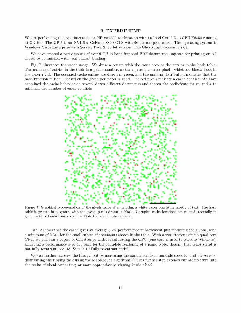
Fig. 7 illustrates the cache usage. We draw a square with the same area as the entries in the hash table.The number of entries in the table is a prime number, so the square has extra pixels, which are blacked out inthe lower right. The occupied cache entries are drawn in green, and the uniform distribution indicates that thehash function in Eqn. 1 based on the glyph perimeter is good. The red pixels indicate a cache conflict. We haveexamined the cache behavior on several dozen different documents and chosen the coefficients for wt and h tominimize the number of cache conflicts.
Figure 7. Graphical representation of the glyph cache after printing a white paper consisting mostly of text. The hashtable is printed in a square, with the excess pixels drawn in black. Occupied cache locations are colored, normally ingreen, with red indicating a conflict. Note the uniform distribution.
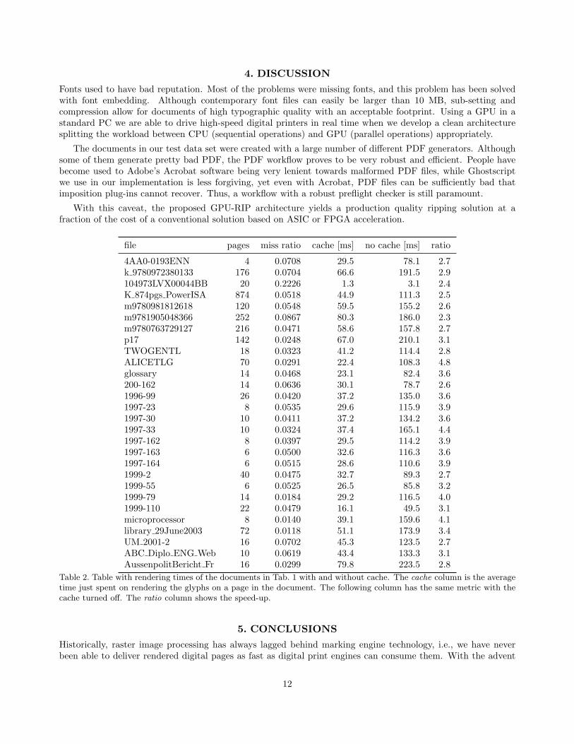
Tab. 2 shows that the cache gives an average 3.2× performance improvement just rendering the glyphs, witha minimum of 2.3×, for the small subset of documents shown in the table. With a workstation using a quad-coreCPU, we can run 3 copies of Ghostscript without saturating the GPU (one core is used to execute Windows),achieving a performance over 400 ppm for the complete rendering of a page. Note, though, that Ghostscript isnot fully reentrant, see [13, Sect. 7.1 “Fully re-entrant code”].
We can further increase the throughput by increasing the parallelism from multiple cores to multiple servers,distributing the ripping task using the MapReduce algorithm.14 This further step extends our architecture intothe realm of cloud computing, or more appropriately, ripping in the cloud.
11
4. DISCUSSIONFonts used to have bad reputation. Most of the problems were missing fonts, and this problem has been solvedwith font embedding. Although contemporary font files can easily be larger than 10 MB, sub-setting andcompression allow for documents of high typographic quality with an acceptable footprint. Using a GPU in astandard PC we are able to drive high-speed digital printers in real time when we develop a clean architecturesplitting the workload between CPU (sequential operations) and GPU (parallel operations) appropriately.
The documents in our test data set were created with a large number of different PDF generators. Althoughsome of them generate pretty bad PDF, the PDF workflow proves to be very robust and efficient. People havebecome used to Adobe’s Acrobat software being very lenient towards malformed PDF files, while Ghostscriptwe use in our implementation is less forgiving, yet even with Acrobat, PDF files can be sufficiently bad thatimposition plug-ins cannot recover. Thus, a workflow with a robust preflight checker is still paramount.
With this caveat, the proposed GPU-RIP architecture yields a production quality ripping solution at afraction of the cost of a conventional solution based on ASIC or FPGA acceleration.
file pages miss ratio cache [ms] no cache [ms] ratio
4AA0-0193ENN 4 0.0708 29.5 78.1 2.7k 9780972380133 176 0.0704 66.6 191.5 2.9104973LVX00044BB 20 0.2226 1.3 3.1 2.4K 874pgs PowerISA 874 0.0518 44.9 111.3 2.5m9780981812618 120 0.0548 59.5 155.2 2.6m9781905048366 252 0.0867 80.3 186.0 2.3m9780763729127 216 0.0471 58.6 157.8 2.7p17 142 0.0248 67.0 210.1 3.1TWOGENTL 18 0.0323 41.2 114.4 2.8ALICETLG 70 0.0291 22.4 108.3 4.8glossary 14 0.0468 23.1 82.4 3.6200-162 14 0.0636 30.1 78.7 2.61996-99 26 0.0420 37.2 135.0 3.61997-23 8 0.0535 29.6 115.9 3.91997-30 10 0.0411 37.2 134.2 3.61997-33 10 0.0324 37.4 165.1 4.41997-162 8 0.0397 29.5 114.2 3.91997-163 6 0.0500 32.6 116.3 3.61997-164 6 0.0515 28.6 110.6 3.91999-2 40 0.0475 32.7 89.3 2.71999-55 6 0.0525 26.5 85.8 3.21999-79 14 0.0184 29.2 116.5 4.01999-110 22 0.0479 16.1 49.5 3.1microprocessor 8 0.0140 39.1 159.6 4.1library 29June2003 72 0.0118 51.1 173.9 3.4UM 2001-2 16 0.0702 45.3 123.5 2.7ABC Diplo ENG Web 10 0.0619 43.4 133.3 3.1AussenpolitBericht Fr 16 0.0299 79.8 223.5 2.8
Table 2. Table with rendering times of the documents in Tab. 1 with and without cache. The cache column is the averagetime just spent on rendering the glyphs on a page in the document. The following column has the same metric with thecache turned off. The ratio column shows the speed-up.
5. CONCLUSIONSHistorically, raster image processing has always lagged behind marking engine technology, i.e., we have neverbeen able to deliver rendered digital pages as fast as digital print engines can consume them. With the advent
12

of programmable GPUs we have finally caught up. The design challenge was the bridging from the CPU to theGPU and back, and we solved this with OpenPL.
As we report in other papers, we have also developed an accurate color manager running on the GPU,15 aswell as a LUT optimizer running on the GPU.16 Finally, in our project17 we are substituting preflight checkingwith print job simulation18 and automatic print quality verification.
ACKNOWLEDGMENTS
We are deeply indebted to our Director Gary Dispoto for providing the leadership and vision for this project.Lloyd Earl Dakin encouraged us to write this paper. Thanks to the HP Indigo product group in Boise andIsrael for their support and encouragement. Thanks as well to Justin Henley and Patti Harrell at AMD/ATI fortheir support. Bill Buzbee and Jeeva Sarvanan have contributed to the general implementation. Ingeborg Tastlprovided valuable feedback on a draft of this paper.
REFERENCES[1] Lampson, B., “Personal distributed computing: the Alto and Ethernet software,” in [Proceedings of the
ACM Conference on The history of personal workstations ], White, J. R. and Kathi, A., eds., 101–131,ACM, New York, NY, USA (January 1986).
[2] Thacker, C. P., “Personal distributed computing: The Alto and Ethernet hardware,” in [Proceedings of theACM Conference on The history of personal workstations ], White, J. R. and Kathi, A., eds., 87–100, ACM,New York, NY, USA (January 1986).
[3] Anonymous, “Adobe PDF Print Engine 2: Powering the next generation of PDF print workflows,” technicalpaper, Adobe (May 2008).
[4] Starkweather, G. K., [Laser applications ], vol. 4, ch. High Speed Laser Printing Systems, 125–140, AcademicPress (1980).
[5] Beretta, G. B. and Meier, A., “Scan converting polygons based on plane-sweep,” External Tech. Report 68,Institut fur Informatik, Eidgenossische Technische Hochschule (August 1986).
[6] Wirth, N., “Program development by stepwise refinement,” Commun. ACM 26(1), 70–74 (1983).[7] Aho, A. V., Hopcroft, J. E., and Ullman, J. D., [Data Structures and Algorithms ], Computer Science and
Information Processing, Addison-Wesley (1983).[8] Fernando, R. and Kilgard, M. J., [The Cg Tutorial: The Definitive Guide to Programmable Real-Time
Graphics ], Addison-Wesley Professional (March 2003).[9] Shreiner, D., Woo, M., Neider, J., and Davis, T., [OpenGL Programming Guide: The Official Guide to
Learning OpenGL, Version 2 ], Addison-Wesley Professional, 5th edition ed. (August 2005).[10] Gelphman, David amd Laden, B., [Programming with Quartz ], The Morgan Kaufmann Series in Computer
Graphics, Elsevier Science & Technology Books (2006).[11] Ghostscript, “http://www.ghostscript.com/.” Web site.[12] Beretta, G. B., “Color aspects of variable data proofing,” in [Internet Imaging VI ], Santini, S., Schettini, R.,
and Gevers, T., eds., IS&T/SPIE Symposium on Electronic Imaging Science & Technology 5670, 175–182,IS&T/SPIE, SPIE, San Jose (California, USA) (January 2005).
[13] Artifex Software, “Ghostscript projects seeking developers.” Web page http://pages.cs.wisc.edu/
~ghost/doc/cvs/Projects.htm (August 2008).[14] Dean, J. and Ghemawat, S., “MapReduce: simplified data processing on large clusters,” Commun.
ACM 51(1), 107–113 (2008).[15] Bhachech, M., Shaw, M., and DiCarlo, J., “Improved color table inversion near the gamut boundary,” in
[Fourteenth Color Imaging Conference; Scottsdale, Arizona ], Bala, R. and Mahy, M., eds., 44 – 49, Societyfor Imaging Science and Technology (IS&T), Society for Information Display (SID) (November 2006).
[16] Tastl, I., Recker, J. L., Zhang, Y., and Beretta, G., “An efficient high quality color transformation,” in[Seventeenth Color Imaging Conference; Albquerque, New Mexico ], Braun, K. and Chorin, M. B., eds.,Society for Imaging Science and Technology (IS&T), Society for Information Display (SID) (November 9 –13 2009).
13

[17] Lin, I.-J., Hoarau, E., Zeng, J., and Dispoto, G., “Proposal for next generation print infrastructure:Gutenberg-Landa TCP/IP,” in [25th International Conference on Digital Printing Technologies ], Yuh, H.-J., ed., Society for Imaging Science and Technology (IS&T), Imaging Society of Japan (ISJ) (September20—24 2009).
[18] Zeng, J., Lin, I.-J., Hoarau, E., and Dispoto, G., “Numerical simulation and analysis of commercial printproduction system,” in [25th International Conference on Digital Printing Technologies ], Yuh, H.-J., ed.,Society for Imaging Science and Technology (IS&T), Imaging Society of Japan (ISJ) (September 20—242009).
14