
Focusing of MeV Ions Using Tapered Insulator Tubes J. Hasegawa, P. Chalermpong, S. Shiba, and Y....
23
Focusing of MeV Ions Using Tapered Insulator Tubes J. Hasegawa, P. Chalermpong, S. Shiba, and Y. Oguri RLNR, Tokyo Tech
-
Upload
roxanne-wilkerson -
Category
Documents
-
view
213 -
download
0
Transcript of Focusing of MeV Ions Using Tapered Insulator Tubes J. Hasegawa, P. Chalermpong, S. Shiba, and Y....

Focusing of MeV Ions Using Tapered Insulator Tubes
J. Hasegawa, P. Chalermpong,
S. Shiba, and Y. Oguri
RLNR, Tokyo Tech

Beam transport experiments with insulator capillaries have been performed for a wide range of beam energies.
• Stolterfoht et al. reported that low-energy highly charged ions (Ne7+) were guided by the charged inner walls of the capillaries on a PET film and ion transmission was drastically enhanced [1].
• Tapered glass capillaries were used to guide not only keV ions but also MeV ions, and beam focusing effects were observed [2,3].
• The micro-beam generator based on the capillary optics is compact and low-cost compared with the conventional ones using collimators and electro-magnets.
• Various applications, such as cell surgery [4], µ-NRA [5], high-resolution X-ray radiography [6], µ-PIXE and has been being studied.
N. Stolterfoht, et al., Phys. Rev. Lett., 88,133201 (2002).
2
[1] N. Stolterfoht, et al., Phys. Rev. Lett., 88, 133201 (2002).[2] T. Ikeda, et al., Appl. Phys. Lett., 89, 163502 (2006). [3] T. Nebili, et al., J. Vac. Sci. Technol. A 21, 1671 (2003).[4] Y. Iwai, et al., Appl. Phys. Lett., 92, 023509 (2008).[5] D. Sekiba, et al., Nucl. Instr. and Meth. B266, 4027 (2008).[6] J. Hasegawa, et al., Nucl. Instr. and Meth. B266, 2125 (2008).
Glass capillary( borosilicate )ø0.1 µm ~ 100 µm
Tip of theglass capillaryø900 nm

How are MeV-ions transmitted in a glass capillary tube?
• The range of the acceptable tilt angle for MeV ions (~10 mrad) are much smaller than that for keV ions (≥200 mrad).
• Small-angle scattering on the capillary inner wall is probably a dominant process for the MeV-ion transport.
• Beam transmission rate for MeV ions reported by the previous studies are much different from each other; the enhancement (focusing) factor ranges from ~5 to more than 104!
• Physics on the beam transmission in tapered glass capillaries is still unclear.
– How large is the contribution of the multiple-scattering on the surface?
– Can the total reflection occur even on the amorphous surface? (like channeling in crystal)
N. Stolterfoht, et al., Phys. Rev. Lett., 88,133201 (2002).
ø8 µm, 2-MeV proton
cut-off cut-off
~ 10 mrad
ø0.1 µm, 3-keV Ne7+

A micro-beam system using the capillary optics has been developed at RNLR, Tokyo Tech.
X-ray detectorX-ray detector
ActuatorsActuators
Glass capillaryGlass capillary
XZ stagesXZ stages
Target holderTarget holder
FaradaycupFaradaycup
Ion beam
Tandem acceleratorTandem accelerator
Focusing magnetFocusing magnet
Irradiation chamberIrradiation chamber
• A large chamber for the micro beam experiment was installed in a beam line of the 1.6-MV tandem facility at Tokyo Tech.
• Various kinds of targets and detectors can be used in the chamber depending on the application (the photo shows a setup for µ-PIXE analysis.)

Beam transmission efficiency for 2-MeV proton was measured for different tip diameters.
• All capillaries have the same taper angle (~40 mrad).• Current integrators were used to accumulate the beam current and
avoid the error due to beam current fluctuation.• Beam intensity was assumed to be uniform at the capillary inlet.
€
εexp =Iout
Iin
=IFC2
(a2 /a1)2(IFC1 + IFC2)Transport efficiency :
€
a1 = 2mm
a2 = 0.8mm
40 mm

The enhancement factor increases with decreasing exit diameter of the capillary.
• Beam loss rate in the straight section was calculated from the experimental results for straight capillaries.
• Beam transmission was much larger than the prediction of the model. (several times ~ 30 times)
• But, there is an uncertainty in the estimation of the incident beam current.
€
εcalc = (1− Cls)(dout /din )2
€
ls :
din :
dout :
Length of straight part
Entrance diameter
Exit diameter
€
1− Cls
€
(dout /din )2
Straight sectionTapered section
Smaller tilt angle is better
for beam focusing?
Smaller tilt angle is better
for beam focusing?
Enhancement
Exp.
Calc.

Beam transmission through the capillary was measured by an improved apparatus.
• The incident proton beam was collimated by two small apertures, which have the same size as the capillary entrance (ø0.8 mm).
• The beam current measured at FC3 without a capillary was regarded as the incident beam current to the capillary.
• A biased thin aluminum foil prevented low-energy ions from entering the Faraday cup and also suppressed the secondary electron emission from the cup.

Beam transmission was evaluated by comparing the beam current with and without a capillary.
Capillary( ø28 µ
m )FC1 FC2 FC3
No I1= 100 nA I2= 0.67 nA I3= 5.1 nA
Yes I’1= 100 nA I’2= 3.7 nA I’3= 0.032 nA
• Enhancement factor was much smaller than estimated before (~20).
→ Because of underestimation of incident beam current or secondary electron emission from the Faraday cup.
• More than 30% of incident ions were “disappeared”.
→ Some part of incident ions may penetrate the capillary wall after large-angle scatterings. But, this cannot explain all…
€
=(I2 + I3) − ( ′ I 2 + ′ I 3) =
Enhancement factor
“Disappeared” current
€
=′ I 3 /I3
(0.028 /0.8)2= 5.1
2 nA

Observation using an imaging plate revealed that the micro beam consists of core and halo.
• From the observation using an imaging plate, we revealed that the micro beam transmitted through the capillary consists of core and halo components .
• The beam divergence of the core part was about 3.3 mrad, which was smaller than the geometrical cut-off angle ( 6 mrad ).
• To measure the energy spectrum of the core particles, we scanned the core part with a silicon semiconductor detector.
8 µm, 0 mrad
10 mm Core
Halo

We confirmed that protons in the core component were transmitted through the capillary without energy loss.
• The FWHM of the peak can be explained by the specific energy resolution of the Si detector (~11 keV) and the energy straggling in an aluminum foil (~10 keV).
• The core intensity was 100-1000 times larger than the neighbor area.
• The beam density enhancement cannot be explained only by the core particles.
~25 keV
[mm]
Energy resolution : 11 keV @ 5.8 MeV He2+
Energy straggling : ~10keV for 2-MeV proton in a 0.8-µm aluminum foil.

Energy spectra of protons consisting the core and the halo were measured by varying the detector angle.
• The detector position with respect to the capillary (beam) axis were controlled by a rotation motorized stage and a motorized goniometer .( Minimum step: H:0.0025˚, V:0.001˚ )
• Total number of particles detected at each position was normalized by incident beam current to get the beam intensity profile.

The beam intensity profile had two peaks.
• Two peaks (sharp and broad) correspond to the core and halo, respectively?• A significant decrease in the beam intensity at the right-hand side of the sharp peak
was due probably to the edge of the capillary exit.• The decrease in the peak energy and the low-energy tail were more remarkable in
the spectrum of the protons detected at the position of the broad intensity peak.
5 cm downstream
Edge effect?

Beam intensity distributions for different energy ranges.
• Core: smaller angular spread ( ~5 mrad ) , better symmetry → “straight-ahead” particles.
• The halo part seems to have a hollow-shape .• The shape of halo distribution was almost independent of the energy range .• Intensity integral → halo : core = 14 : 1 → 15 times enhancement?

Halo component is responsible to beam enhancement.But, there are disagreements in its amount.
• Typical E for halo particles:
• Kinematic factor for elastic scattering :
• TRIM failed to explain the E quantitatively.
€
K =1− (M1 / M2)2 sin2 θ[ ]
1/ 2+ (M1 / M2)cosθ
1+ (M1 / M2)
⎧ ⎨ ⎪
⎩ ⎪
⎫ ⎬ ⎪
⎭ ⎪
2
0.12-0.13 MeV
€
E ~
• Halo component with hollow structure
→ Small number of scattering per proton.
• No angular dependency of intensity distribution.
→ Low energy tail was due dominantly to scattering “in” the glass wall?
• Beam enhancement is attributed to halo component .Beam current measurement : ~ 20x ( overestimation?)
Beam current measurement: ~ 5x
Particle count measurement: ~ 15xDisagreement!
K ~ 1 @15 mrad, M1/M2 ~ 1/19 → no energy loss??
(0.86 deg)
TRIM

A Monte-Carlo (MC) code was originally developed to simulate MeV-ion transmission in tapered capillaries.
• Stopping-power and range data can be imported seamlessly from the SRIM database [1].
• Not only elemental material but many kinds of compounds can be used as the wall material. “Borosilicate” was chosen for the present case.
• In the present status, only elastic scattering is taken into account as an interaction process between a projectile and a target atom.
• The classical Rutherford scattering formula is used for the calculation of the scattering cross section because the shielding effect is not so important for swift ions with energies more than 1 MeV.
• Neither the multiple-scattering effect nor the surface effect is not included. But, these effects should be considered in the future.
• The code is designed to have an object-oriented structure (ANSI C++), which makes it easy to apply it to various kinds of problems.

Transmission of 2-MeV protons were examined in various taper angle capillaries.
• The guiding effect is stronger with smaller taper angle.
• Most of the detected particles experienced only one collision in the capillary.
Taper angle = 1 mrad
Taper angle = 2 mrad
Taper angle = 3 mrad
Taper angle = 3 mrad

The hollow structure in the halo-particle distribution on the detector was well reproduced.
• The mean radius of the hollow structure increased with increasing taper angle.
• The overlap between the core and the halo was observed also in MC calculations with a small tilt angle with respect to the beam axis.
Taper angle = 1 mrad Taper angle = 2 mrad Taper angle = 3 mrad
Taper angle = 1 mradTilt angle = 1 mrad

Dependency of the halo particle energy on the divergence angle (= scattering angle) was weak.
• The result indicates that scattering occurred not only on the surface but also in the wall.
• The calculated energy spectrum for halo particles well reproduced the observed one.
MC
Exp.
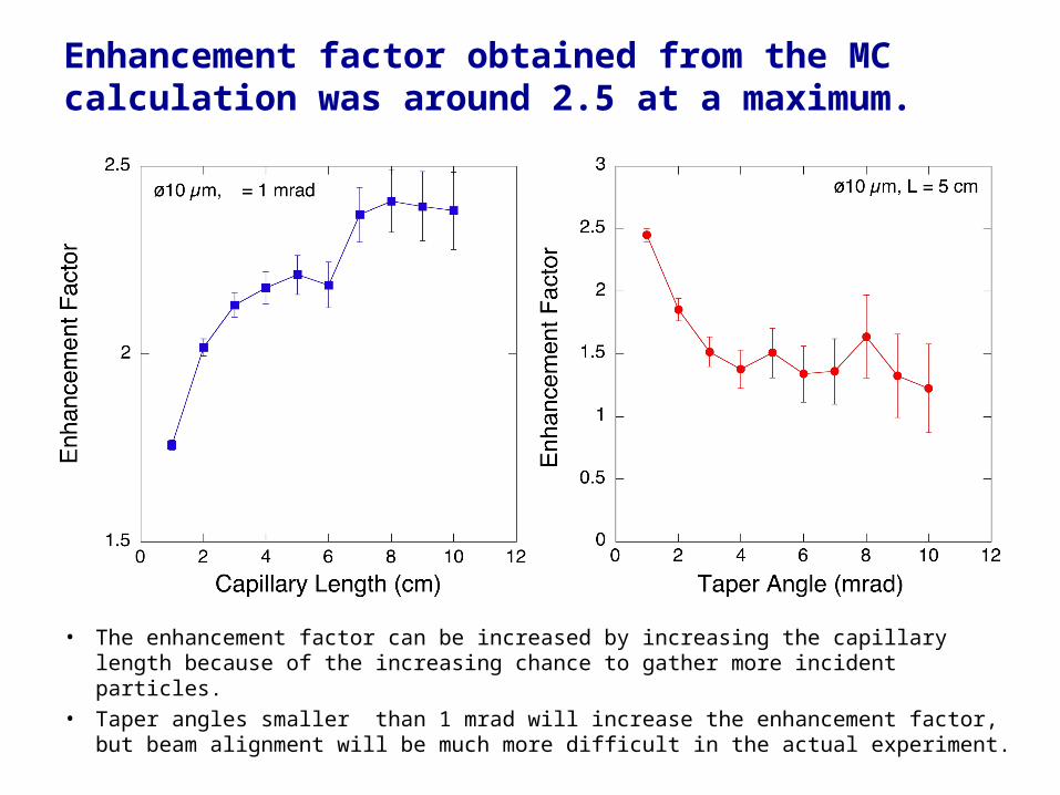
Enhancement factor obtained from the MC calculation was around 2.5 at a maximum.
• The enhancement factor can be increased by increasing the capillary length because of the increasing chance to gather more incident particles.
• Taper angles smaller than 1 mrad will increase the enhancement factor, but beam alignment will be much more difficult in the actual experiment.

Two-dimensional element mapping using glass capillary optics was demonstrated at the first time.
Copper mesh ( #1000 )
Intensity of Cu-K Xray :
• Beam: 2 MeV Proton• Current: ~100 pA• Capillary outlet: ø10 µm• Distance = 1 mm• Sample : Cu Mesh #1000• Measurement time = 30 s/step• Step size = 2 µm• Total measurement time : ~ 4 hr
8 μm
60 µm
14 µm

Summary
• The proton beam transmitted through the capillary consisted of the two components, core and halo.
• The particles in the core component had a monochromatic energy, which indicates that the particles pass through the capillary without collision.
• From the amount of the energy loss, most of the halo particles experienced only one scattering in the glass capillary, which was also indicated by the Monte-Carlo simulation.
• The Monte-Carlo calculation well reproduced the transmitted proton distribution and the halo particle energy spectrum.
• To fill the gap among the evaluations of the enhancement factor, the accuracy of the measurement should be improved and the more precise treatment of surface scattering in the MC code is needed.
• It is interesting to apply the tapered capillary optics to the final focusing of the intense pulsed beam in WDM experiments. It may be able to assist the beam intensity magnification.

The core is surrounded by “quasi”-core particles.
Core5 mm
• Beam diameter
Core: ~1 mm, quasi-core: ~3 mm
• Divergence angle
Core: ~ 2 mrad, quasi-core: ~6 mrad
• Cutoff angle: ~20 mrad
“quasi”-core

Energy spectra of “quasi”-core particles.
Horizontal
• Broad peaks in low-energy region were observed. Depending on the number of collisions?
• Peak energy positions were shifted towards low-energy side with increasing distance from the core .
H:0mm, V: -1mm


