Focus 1 - Microcon · User Guide 1 / 4 HP to 2 HP Adjustable Voltage DC Drive Focus 1 359 Lang...
39
User Guide 1 /4 HP to 2 HP Adjustable Voltage DC Drive Focus 1 359 Lang Boulevard, Building B Grand Island, New York 14072 USA (716) 774-1193 • Fax: (716) 774-8327 Division of Emerson Electric Co. FOCUS1/UG February 1997 Printed in USA
-
Upload
phungquynh -
Category
Documents
-
view
215 -
download
2
Transcript of Focus 1 - Microcon · User Guide 1 / 4 HP to 2 HP Adjustable Voltage DC Drive Focus 1 359 Lang...

User Guide
1/4 HP to 2 HPAdjustable Voltage DC Drive
Focus 1
359 Lang Boulevard, Building BGrand Island, New York 14072 USA
(716) 774-1193 • Fax: (716) 774-8327
Division of Emerson Electric Co.
FOCUS1/UGFebruary 1997 Printed in USA

The drive stop and start inputs should not be relied upon alone to ensurethe safety of personnel. If a safety hazard could arise from the unexpect-ed starting of the drive, a further interlock mechanism should be providedto prevent the motor from running except when it is safe to do so.
The manufacturer accepts no liability for any consequences resulting frominappropriate, negligent or incorrect installation or adjustment of theoptional operating parameters of the equipment, or from mismatching ofthe drive to the motor.
The contents of this guide are believed to be correct at the time of print-ing. In the interests of a commitment to a policy of continuous develop-ment and improvement, the manufacturer reserves the right to change thespecification of the product or its performance or the contents of theUser’s Guide without notice.
All rights reserved. No part of this book may be reproduced or transmit-ted in any form or by any means, electronic or mechanical, including pho-tocopying, recording, or by any information storage or retrieval systemwithout permission from the publisher in writing.
Copyright © 1994 Control Techniques Drives, Inc.
WARRANTY
Control Techniques Drives (CT) warrants to the buyer who purchases for use and not forresale that the equipment described in this manual is sold in accordance with CT’s pub-lished warranty statement (document # GEN-030) and CT’s published terms and condi-tions (document # GEN-031). Copies of these documents may be obtained from any DriveCenter listed below.
For product technical support and/ or copies of this User guide, please contact the DriveCenter nearest you:
For on-site Field Service assistance, please contact:
AMERICAS’ SERVICE CENTERControl Techniques Drives359 Lang Boulevard, Building BGrand Island, NY 14072Phone 8:00 A.M. to 5:00 P.M. EST: . . . . . . 716-774-1193After Hours: . . . . . . . . . . . . . . . . . . . . . . 716-692-2442Fax: . . . . . . . . . . . . . . . . . . . . . . 716-774-8327
CALIFORNIAADI/Control Techniques DrivesSan Francisco Drive Center2512 Tripaldi WayHayward, CA 94545Phone: 510-264-4940Fax: 510-264-4949
ILLINOISControl Techniques DrivesChicago Drive Center95 Brandon DriveGlendale Heights, IL 60139Phone: 708-893-5249Fax: 708-893-4156
OHIO Control Techniques DrivesCincinnati Drive Center1125 Petersburg RoadHebron, KY 41048Phone: 606-689-4900Fax: 606-689-5344
OHIO Control Techniques DrivesCleveland Drive Center6900 Southpointe ParkwayBrecksville, OH 44141Phone: 216-717-0123Fax: 216-717-0133
NORTH CAROLINAControl Techniques DrivesCharlotte Drive Center2716 Interstate StreetCharlotte, NC 28208Phone: 704-393-3366Fax: 704-393-0900
RHODE ISLAND Control Techniques DrivesProvidence Drive Center4 Blackstone Valley PlaceLincoln, RI 02865Phone: 401-333-3331Fax: 401-333-6330
TEXASControl Techniques DrivesDallas Drive Center1226 Exchange DriveRichardson, TX 75081Phone: 214-783-1831Fax 214-783-9978———————————————ONTARIO - CANADAControl Techniques DrivesToronto Drive Center9999 Highway 48Markham, ON Canada L3P 3J3Phone: 905-475-4699Fax: 905-475-4694

TABLE OF CONTENTS
TITLE ........................................................................PAGE
1 SAFETY1.1 General Safety Precautions .................................................11.2 Installation Safety ................................................................21.3 Start-up Safety....................................................................3
2 GENERAL INFORMATION2.1 Introduction.........................................................................52.2 General Description.............................................................52.3 Typical Packaging ...............................................................62.4 Equipment Identification......................................................7
3 CONTROL SPECIFICATIONS AND FEATURES3.1 Equipment Ratings..............................................................93.2 Service Conditions ............................................................103.3 Performance Specifications...............................................103.4 Operator Functions ...........................................................113.5 Potentiometer Adjustments...............................................113.6 Customer Programmable Selections (Jumpers).................113.7 Standard Features ...........................................................113.8 Pre-Engineered Modification Kits ......................................12
3.8.1 "M" Contactor Kit .........................................................................123.8.2 Magnetic Reversing Kit.................................................................133.8.3 NEMA 4/12 Conversion Kit...........................................................133.8.4 Dynamic Braking Kit .....................................................................143.8.5 Spare Parts Kit .............................................................................14
4 INSTALLATION4.1 Safety Warnings................................................................154.2 Initial Checks.....................................................................154.3 Control Jumper Programming...........................................154.3.1 Mode of Control Selection .............................................174.3.2 Operating Voltage Selection .........................................174.3.3 Current Limit Level Selection..........................................184.4 Determining the Control Location......................................194.5 Installing Panel Mount Controls .........................................194.6 Installing Enclosed Controls ..............................................194.7 Power Wiring ....................................................................204.7.1 Incoming Power Requirements ......................................204.7.2 Output Power Ranges ...................................................214.7.3 Output Terminal Installation Checks ...............................214.7.4 Output Power Connections............................................234.8 Panel Mount Control Logic and Signal Wiring ...................23
i

TITLE ........................................................................PAGE
4 INSTALLATION (Cont.'d)4.9 Enclosure Mount Control Logic and Signal Wiring.............254.10 Installing Modifications ....................................................25
5 OPERATION AND STARTUP PROCEDURE
5.1 Introduction.......................................................................275.2 Start-up Procedure ...........................................................275.2.1 Pre-Start Equipment Checks .........................................275.2.2 Operation and Adjustment..............................................27
6 FUNCTIONAL DESCRIPTION6.1 Power Bridge and Field Supply .........................................316.2 Start/Stop Logic................................................................326.3 Regulator Circuitry ............................................................346.4 Power Supplies.................................................................35
7 MAINTENANCE AND TROUBLESHOOTING7.1 Important Safeguards .......................................................377.2 Routine Maintenance ........................................................377.3 Troubleshooting Overview .................................................387.3.1 Suggested Training.........................................................387.3.2 Maintenance Records.....................................................387.3.3 General Troubleshooting.................................................387.3.4 Notes for a Troubleshooting Technician ..........................397.4 Basic Troubleshooting.......................................................39
8 ORDERING SPARE PARTS ....................................................43
9 SUPPLEMENTARY TECHNICAL INFORMATION ..................45
TITLE .....................................................................PAGE
10 BASIC APPLICATION INFORMATION10.1 Basic Mechanics ........................................................5510.1.1 Torque .....................................................................5510.1.2 Horsepower.............................................................5510.2 Torque vs. Horsepower ..............................................5510.3 Matching the Drive to the Machine .............................5510.3.1 Breakaway Torque...................................................5610.3.2 Accelerating Torque.................................................5610.3.3 Running Torque .......................................................5610.4 DC Drive Characteristics.............................................5810.4.1 Constant Torque Applications..................................5810.4.2 Constant Horsepower Applications .........................5810.5 Other Mechanical Considerations ...............................5910.5.1 Constant Torque Speed Range ...............................5910.5.2 Torque Limitations ...................................................5910.5.3 Duty Cycle...............................................................5910.5.4 Overhauling Loads...................................................5910.6 Motor Application Formulas........................................6010.6.1 Calculating Horsepower ..........................................6010.6.2 Inertia (WK2) ............................................................6110.6.3 WK2 of Rotating Elements .......................................6410.6.4 WK2 of Linear Motion ..............................................6410.7 Electrical Formulas .....................................................6410.8 Other Useful Formulas................................................65
Appendix A Glossary...................................................................67
ii iii

LIST OF ILLUSTRATIONS
FIGURE ......................................................................................PAGE
1-1 Oscilloscope Connections .....................................................4 2-1 Panel Mounted Control ..........................................................62-2 Enclosure Mounted Control ...................................................7 2-3 Typical Panel Mount Product Nameplate ...............................82-4 Enclosure Mount Control Product Nameplate Location .........82-5 Typical Enclosure Mount Product Nameplate ........................83-1 "M" Contactor Kit ................................................................123-2 Magnetic Reversing Kit ........................................................133-3 Dynamic Braking Kit ............................................................14
4-1 Panel and Enclosure Mount PC Board Jumper Locations ...164-2 Connection of AC Power and Motor Leads to
Panel and Enclosure Mount Controls...................................204-3 Panel Mount Start/Stop and
Potentiometer Connections .................................................24
6-1 Power Bridge Assembly.......................................................316-2 Panel Mount Start/Stop Logic .............................................336-3 Enclosure Mount Start/Stop Logic .......................................336-4 Control Circuit Block Diagram..............................................34
9-1 Outline and Mounting Dimensions for Panel Mount andEnclosure Mount Controls ...................................................46
9-2 Connection Diagram for Panel Mount Controls ....................479-3 Connection Diagram for Enclosed Controls .........................489-4 Panel Mount Control With Armature Contactor and
Dynamic Braking .................................................................499-5 Enclosed Control With Armature Contactor and
Dynamic Braking .................................................................509-6 Panel Mount Control with Reversing and Dynamic Braking..519-7 Enclosed Control with Reversing and Dynamic Braking .......529-8 Schematic Diagram, Panel Mount Control ..........................53 9-9 Schematic Diagram, Enclosure Mount Control.....................54
10-1 Example of 10 lb-ft Applied Torque......................................5510-2 Constant Torque ..................................................................57 10-3 Constant Horsepower..........................................................5710-4 Variable Torque ....................................................................5710-5 Motor Armature Voltage Control and Field Control...............5810-6 Constant Torque Speed Range............................................59
LIST OF TABLES
TABLE ......................................................................................PAGE
3-1 Control Rating Table ..............................................................94-1 Jumper Programming ..........................................................189-1 Control Standard Connection Scheme
Terminal Blocks TB1 and TB2..............................................459-2 Customer Jumper Programming Chart ................................45
10-1 Inertia of Steel Shafting........................................................6210-2 Density Factors....................................................................63
iv v

SECTION 1SAFETY
This section outlines procedures necessary to insure safe operation of any ACor DC drive. For further information, contact the Service Department at theaddress shown on the inside back cover of this manual.
1.1 GENERAL SAFETY PRECAUTIONS
WARNING
THIS CONTROL AND ASSOCIATED MOTOR CONTAINS HAZ-ARDOUS VOLTAGES AND ROTATING MECHANICAL PARTS. EQUIP-MENT DAMAGE OR PERSONAL INJURY CAN RESULT IF THE FOL-LOWING GUIDELINES ARE NOT OBSERVED.
1. Only qualified personnel familiar with this equipment and the information sup-plied with it should be permitted to install, operate, troubleshoot or repair theapparatus. A qualified person must be previously trained in the following pro-cedures:
a) Energizing, de-energizing, clearing, grounding and tagging circuits andequipment in accordance with established safety practices.
b) Caring and using protective equipment such as rubber gloves, hard hat,safety glasses or face shields, flash clothing, etc., in accordance withestablished safety practices.
c) Rendering First Aid
2. Installation of the equipment must be done in accordance with the NationalElectrical Code and any other state or local codes. Proper grounding, con-ductor sizing and short circuit protection must be installed for safe operation.
3. During normal operation, keep all covers in place and cabinet doors shut.
4. When performing visual inspections and maintenance, be sure the incomingAC power is turned off and locked out. The drive and motor will have haz-ardous voltages present until the AC power is turned off. The drive contactordoes not remove hazardous voltages when it is opened.
5. When it is necessary to make measurements with the power turned on, do nottouch any electrical connection points. Remove all jewelry from wrists and fin-gers. Make sure test equipment is in good, safe operating condition.
6. While servicing with the power on, stand on some type of insulation, beingsure you are not grounded.
7. Follow the instructions given in this manual carefully and observe all warningand caution notices.
vi 1

1.2 INSTALLATION SAFETYWhen moving this control and associated motor into the installation position,
do any required lifting only with adequate equipment and trained personnel.Eyebolts or lifting hooks, when supplied, are intended for lifting the product onlyand must not be used to lift additional weight. Improper lifting can cause equip-ment damage or personal injury.
WARNING
HAZARDOUS VOLTAGES MAY BE PRESENT ON EXTERNAL SUR-FACES OF UNGROUNDED CONTROLS. THIS CAN RESULT IN PER-SONAL INJURY OR EQUIPMENT DAMAGE.
IF THE DRIVE CABINET OR OPEN CHASSIS UNIT IS MOUNTEDSUCH THAT IT IS NOT GROUNDED, A GROUND WIRE MUST BECONNECTED TO THE PANEL OR ENCLOSURE FRAME FOR PER-SONNEL SAFETY. ALSO ANY MOTOR FRAME, TRANSFORMERENCLOSURE AND OPERATOR STATION MUST BE CONNECTED TOEARTH GROUND. CONSULT THE NATIONAL ELECTRICAL CODEAND OTHER LOCAL CODES FOR SPECIFIC EQUIPMENT GROUND-ING REQUIREMENTS.
PROTECTIVE GUARDS MUST BE INSTALLED AROUND ALLEXPOSED ROTATING PARTS.
CAUTION
Drilling or punching can create loose metal chips.This can result inshorts or grounds that can damage the equipment.
If it is necessary to drill or punch holes in the equipment enclosures for con-duit entry, be sure that metal chips do not enter the circuits.
Circuits shown on the drawings that require shielded cable are sensitive topick-up from other electrical circuits. Examples include wiring from the tachome-ter and from the speed setting device. Erratic or improper operation of theequipment is likely if the following precautions are not observed:
1. Where shielded cable is required, use 2- or 3- conductor twisted and shield-ed cable with the shield either connected as shown in the drawings, or “float-ing”, if so specified. If the shield is to be connected, do so only at the speci-fied terminal in the drive unit. Do not connect at a remote location.
2. Shielded cables outside the drive enclosure should be run in separate steelconduit, and should not be mixed in with other circuits that are not wired withshielded cable.
3. Inside the drive equipment, whenever possible, avoid running the shieldedcable close to other circuits. Avoid long parallel runs to other non-shielded cir-cuits, and cross other cable bundles at right angles.
Do not connect any external circuits to the drive or its associated equipmentother than those shown on the diagrams supplied. Connection of externaldevices to the tachometer or speed setting device can significantly affect driveperformance.
CAUTION
Meggering circuits connected to the drive can cause damage toelectronic components. Do not megger or hi-pot this equipment. Usea battery operated Volt-Ohm-Meter (VOM) to check for shorts, opensor mis-wiring.
Connection of unsuppressed inductive devices to the drive powerfeed or control circuits can cause mis-operation and possible com-ponent damage to the equipment.
Do not connect power factor correction capacitors with this equip-ment, as this may cause high voltages that can damage the drive.
1.3 Start-up SafetyDetailed startup procedures are described in the Operation and Startup
Section of this manual. Before and during startup, it is imperative that all of thefollowing safety procedures be observed.
WARNING
AC POWER MUST BE DISCONNECTED FROM THE DRIVE CABINETTO ELIMINATE THE HAZARD OF SHOCK BEFORE IT IS SAFE TOTOUCH ANY OF THE INTERNAL PARTS OF THE DRIVE. CIRCUITSMAY BE AT LINE POTENTIAL WHETHER THE ENCLOSED DRIVE ISOPEN OR CLOSED. USE EXTREME CAUTION.
ALSO, HAZARDOUS VOLTAGES ARE PRESENT ON THE MOTORUNTIL ALL POWER TO THE CONTROL IS DISCONNECTED.
TURN OFF AND LOCK-OUT ALL POWER TO THE CONTROLBEFORE TOUCHING ANY INTERNAL CIRCUITS ON THE MOTOR.
1. The use of unauthorized parts in the repair of this equipment or tampering byunqualified personnel will result in dangerous conditions which can causeequipment damage or personal injury. Follow all safety precautions containedin this manual and all safety warning labels on the product.
2. Loose rotating parts can cause personal injury or equipment damage.
2 3

Before starting the motor, remove all unused shaft keys and any other looseparts on the motor or the rotating mechanical load. Be sure all covers and pro-tective devices are in place. Refer to the instruction manual supplied with themotor for further information and precautions.
3. When using an oscilloscope to make measurements in the power circuits, usethe connections shown in Figure 1-1 and the procedures described in step 4.Failure to follow this procedure could result in the case of the oscilloscopebeing at line potential. Only qualified personnel should be allowed to use theoscilloscope and other test equipment.
4. Referring to Figure 1-1, set the oscilloscope to add channels A & B, and invertchannel B. Before making measurements, connect both probes together andset the “zero” line.
This connection allows the oscilloscope case to be connected to ground for safeoperation.
Figure 1-1.Oscilloscope Connections
4
SECTION 2GENERAL INFORMATION
2.1 INTRODUCTIONThis instruction manual contains installation information, operating instruc-
tions, and troubleshooting procedures for this adjustable voltage DC drive. It alsoincludes a complete description of the control with detailed product specifica-tions and a complete description of all customer selectable functions and cus-tomer installable option kits.
For most drive applications, the information contained in this instruction man-ual will completely describe all drive system set-up and operating procedures. Itshould also provide all the information required by the customer to install andmaintain the control. In a few applications, additional drive system set-up andoperating information may be required. This information will generally be fur-nished in the form of system schematic and system interconnection diagrams.An overall Systems Installation Manual may also be furnished.
This instruction manual should be read in its entirety before beginning instal-lation and before performing any start-up or maintenance on the drive system.
NOTEThe information in this manual applies to both the panel mount and enclo-sure mount controls except where specifically stated otherwise.
2.2 GENERAL DESCRIPTIONThe control is a high performance DC drive. It contains all the required cir-
cuitry to control the speed of, or to control the current supplied to, small horse-power shunt wound or permanent magnet DC motors. It includes many standardfeatures that are available only as options on other single phase DC drives. Thisallows the control to be used in custom engineered applications as well as stan-dard speed regulated applications.
The DC motor speed is controlled by varying the DC voltage applied to themotor armature, or the motor torque is controlled by varying the current appliedto the motor armature.
Single phase AC input power is converted to variable voltage DC outputpower by the control. In speed regulated applications, the DC output voltagevaries as a function of an input reference voltage. Typically, the input referencevoltage is provided by an operator adjustable potentiometer. Changing thepotentiometer setting (reference) results in a motor speed change. In torque reg-ulated applications, the DC output current varies as a function of an input refer-ence voltage. Changing the torque reference changes the current supplied tothe motor and results in a change in motor torque output.
The control is designed to handle most single phase drive applications with-out the need for costly, time-consuming engineering.
5
Oscilloscope
ChannelA
ChannelB
Ground ScopeCase
2 x X100 Probes(Remove Ground Clips)
Connect toCircuit Under Test

Simple jumper programming allows for maximum versatility in the drive.Functions such as input voltage selection (120/240 VAC), armature voltageselection (Low - 90 VDC, High - 180 VDC), motor current range (High, Medium,and Low), and speed/current regulation are achieved by customer selection ofthe jumper positions. Refer to Section 4 for details on all jumper programming.Each control is also provided with standard adjustments for maximum/minimumspeed and IR compensation.
A panel mounted and an enclosure mounted model are available, both ofwhich can handle the entire 1/4 to 2 HP range of applications. The enclosuremounted model is provided with a rugged dust and oil-tight enclosure with asmart, modern design that adds eye appeal to the customer’s machine. A NEMA4/12 conversion kit is also available for the enclosure.
2.3 TYPICAL PACKAGINGThe panel mounted control is suitable for sub-panel mounting inside a cus-
tomer supplied control enclosure (See Figure 2-1).
Figure 2-1.Panel Mounted Control
The enclosure mounted control is furnished in a NEMA 1 enclosure that pre-cludes the entry of dust and oil droplets into the electronic hardware. The enclo-sure is intended for use in general purpose environments.
A NEMA 4/12 conversion kit is available for the enclosure. It includes a covergasket and protective boots for the potentiometer and switches.
The enclosure package consists of two halves of a shell which are taken apartby removing the four mounting screws in the corners of the cover. As shown inFigure 2-2, the inside of the cover contains the switches and heatsink. The insideof the base contains the PC board, the functions of which are described in detailin Sections 4 and 5.
Figure 2-2.Enclosure Mounted Control
2.4 EQUIPMENT IDENTIFICATIONIt is important to identify the control completely and accurately whenever
ordering spare parts or requesting assistance in service.
The panel mounted controls include a product nameplate located along thetop edge of the panel as shown in Figure 2-1. The product nameplate shouldappear similar to the sample nameplate shown in Figure 2-3. Record the partnumber (P/N), revision level (REV), and date for future reference in the front of thismanual.
The enclosure mounted controls include a product nameplate located on thebottom edge of the cover as shown in Figure 2-4. The product nameplate shouldappear similar to the sample nameplate shown in Figure 2-5. Record the partnumber (P/N), revision level (REV), and date for future reference in the front of thismanual.
If the control is part of an engineered drive system, the system cabinet willalso include a product nameplate. Record the part number (P/N), and serial num-ber (S/N) of the engineered system and include this information with the infor-mation on the individual controls whenever contacting the factory.
6 7

Figure 2-3.Typical Panel Mount Product Nameplate
Figure 2-4.Enclosure Mount Control Product Nameplate Location
Figure 2-5.Typical Enclosure Mount Product Nameplate
8
SECTION 3CONTROL SPECIFICATIONS AND FEATURES
3.1 EQUIPMENT RATINGSBoth the panel and enclosure mounted controls can be programmed for
120VAC input (1/4-1HP) or for 240VAC input (1/2-2HP). Table 3-1 summarizes thehorsepower outputs available in each programming mode.
Table 3-1Control Rating Table
** DC DC FIELD\AC INPUT ARMATURE OUTPUT OUTPUT
VOLTS AMPS HP VOLTS AMPS* VOLTS AMPS*
3.6 1/4 90 2.6 100 1120 5.2 1/3 90 3.7 100 1VAC 7.7 1/2 90 5.5 100 1
50/60 10.5 3/4 90 7.5 100 1Hz 14 1 90 10 100 1
3.6 1/2 180 2.6 200 1240 5.2 3/4 180 3.7 200 1VAC 7.7 1 180 5.5 200 1
50/60 10.5 1-1/2 180 7.5 200 1Hz 14 2 180 10 200 1
* These are typical motor current ratings. See motor nameplate for exact current ratings.** The input voltage and current (amp) values are approximate. Actual values may vary depending on input voltage, input
line impedance, and actual motor efficiency. A fused AC line disconnect or circuit breaker is required by the NationalElectrical Code. This AC line disconnect or circuit breaker must be installed ahead of the control.
NOTEThe following data is equally applicable to both the panel and enclosuremount controls unless specifically stated otherwise.
9
PN2400-8001 REV DATE1/4 1 HP (115VAC) / 1/2 2HP (230VAC)
INPUT 50/60HZ 14 A MAXOUTPUT 90/180VDC 10 A MAXFIELD 100/200VDC 1 A MAXINDUSTRIAL CONTROL EQUIP
2400-5015 E
PN2400-8000 REV DATE1/4 1 HP (115VAC) / 1/2 2HP (230VAC)
INPUT 50/60HZ 14 A MAXOUTPUT 90/180VDC 10 A MAXFIELD 100/200VDC 1 A MAXINDUSTRIAL CONTROL EQUIP
2400-5011 E

10
3.2 SERVICE CONDITIONSENCLOSURE: .......................................Chassis (panel mount)
......................................................NEMA 1 TENV (enclosure mount)
HORSEPOWER RATINGS:Input Power: 120VAC, 1 phase, 50/60 Hz: ............1/4-1 HP240VAC, 1 phase, 50/60 Hz : ..........1/2-2 HP
LINE VOLTAGE VARIATION: ...............±10%
LINE FREQUENCY VARIATION: ...........48 - 62Hz
FIELD SUPPLY: ................................1 amp
MAXIMUM ALTITUDE (WITHOUT DERATING): ........................3,300 feet above sea level
AMBIENT TEMPERATURE: ................0°C to 55°C (32oF to 131oF).................................................... (panel mount).....................................................0°C to 40°C (32oF to 104oF).................................................... (enclosure mount)
SPACE REQUIREMENT FORPANEL MOUNT IN TOTALLYENCLOSED NON-VENTILATED.............20" x 20" x 8" or(TENV) ENCLOSURE: ............................24" x 20" x 6"
AC LINE FUSES: ...................................15A, 250V
3.3 PERFORMANCE SPECIFICATIONSSERVICE FACTOR:................................1.0 maximum rating
SPEED REGULATION:For a 95% Load ChangeUsing Armature VoltageFeedback with IR Compensation: .....±1% of maximum speed
For All Other Variables(Voltage Regulated): ..........................Changes up to 15% of top speed can .........................................................result from temperature, voltage, .........................................................frequency variations and drift.
OVERLOAD CAPACITY..........................(as a percent of maximum rating):..........150% for one minute
ACCELERATION TIME (Fixed):...............2 to 3 seconds
EFFICIENCY:Control Only (Minimum).....................98%Motor and Control (Typical) ...............86%
CURRENT LIMIT (Fixed):........................150% of selected rating
3.4 OPERATOR FUNCTIONSSPEED ADJUSTMENT: ..........................Standard
POWER ON/OFF, START/STOP: ...........Panel Mount: ....................................Customer suppliedEnclosure Mount: ..............................Standard
FORWARD/REVERSE:...........................Optional
3.5 POTENTIOMETER ADJUSTMENTSThe standard control includes three (3) customer adjustable potentiometers
which are located on the printed circuit board. These potentiometers have beenpreset. However, for proper operation in some applications, minor readjustmentsmay be necessary during drive installation and startup.MAXIMUM SPEED: ........................... 70 to 115% of rated speedMINIMUM SPEED: ............................ 0 to 30% of maximum speedIR COMPENSATION: ........................ 0 to 20% of rated voltage at rated current
3.6 CUSTOMER PROGRAMMABLE SELECTIONS (JUMPERS)
MODE OF CONTROL: ......................Speed or torque regulationOPERATING VOLTAGE: ....................120 or 240 VACCURRENT LIMIT LEVEL:...................High, Medium, or Low
3.7 STANDARD FEATURES• Compact and lightweight:
—Panel mount control only 3 pounds
—Enclosure mount control only 4 pounds
• Control relay providing momentary Start/Stop operation. Control cannot restartwithout pushing Start button if AC power is momentarily disconnected andrestored.
• Current limiting to protect drive from overloads. Automatically adjusts to 150%of selected current rating.
• Continuous full rated torque over a 30:1 speed range.
• Run LED (light emitting diode) indicator light.
• Zener regulated control power supply provides compensation for line voltagefluctuation.
11

• Integrated circuit operational amplifier for high gain, fast response, and excel-lent linearity.
• Full wave encapsulated SCR bridge power cube.
• Varistor transient voltage protection providing trouble - free operation.
• UL and cUL listed.
3.8 PRE-ENGINEERED MODIFICATION KITSThe control can be purchased alone or with a selected group of pre-engi-
neered modification kits. These kits allow the customer to create a custom engi-neered control to meet individual specific requirements. Each modification kit isindividually packaged, identified, and includes all mounting hardware, wire, ter-minals, cable ties, labels and instructions. Paragraphs 3.8.1 through 3.8.5 pro-vide a brief description of the modification kits currently available:
CAUTION
These modification kits are the only kits designed for use with thiscontrol. Any modifications other than those specified by ICD Drives,Inc., voids all warranties, stated or implied.
Figure 3-1."M" Contactor Kit
3.8.1 "M" Contactor KitThis kit shown in Figure 3-1, includes a magnetic contactor which can be
mounted inside the enclosed control or directly on the chassis mount unit. Thiscontactor provides a positive disconnect of the motor armature when the controlis stopped, preventing motor turnover in case the SCRs should false fire. Notethat this kit may be required by local and/or national electrical codes.
12 13
Figure 3-2.Magnetic Reversing Kit
3.8.2 Magnetic Reversing KitThis kit, shown in Figure 3-2, includes forward and reverse contactors which
can be mounted inside the enclosed control or on the chassis mount unit. Alsoprovided is a forward/reverse toggle switch for selecting the direction of motorrotation. The electrical code requirements for an "M" contactor are also satisfiedsince the forward and reverse contactors disconnect the motor armature from thecontrol when the motor is stopped. This switch may be mounted in the cover ofthe enclosed control or in the customer's operator control panel. Note that this kitprovides no anti-plugging protection. The motor must be allowed to reach a com-plete stop before starting in opposite rotation. When anti-plugging protection isrequired, use the Focus 2 Control.
3.8.3 NEMA 4/12 Conversion KitThe standard enclosed control is provided in a TENV enclosure rated NEMA
1. For protection from a more rigorous industrial environment, the NEMA 4/12 Kitmay be used. This kit converts the standard enclosure into one which meetsNEMA 4 or 12 requirements. It includes a gasket which provides a tight sealaround the enclosure cover, switch boots which seal the operator control switch-es and a shaft sealing nut for the potentiometer.

14
SECTION 4INSTALLATION
4.1 SAFETY WARNINGSImproper installation or operation of this control may cause injury to personnel
or damage to equipment. Read the operating instructions. The control and itsassociated motors and operator control devices must be installed and groundedin accordance with all local codes and the National Electrical Code (NEC). Toreduce the potential for electric shock, disconnect all power sources before initi-ating any maintenance or repairs. Keep fingers and foreign objects away fromventilation and other openings. Keep air passages clear. Potentially lethal volt-ages exist within the control unit and connections. Use extreme caution duringinstallation and start-up.
4.2 INITIAL CHECKSBefore installing the control, check the unit for physical damage sustained
during shipment. If damaged, file claim with shipper and return for repair follow-ing procedures outlined on the back cover. Remove all shipping restraints andpadding. Check nameplate data for conformance with the AC power source andmotor.
4.3 CONTROL JUMPER PROGRAMMINGPrior to installing the control, the jumpers must be programmed for all of the
following:
1. Using either the speed or torque regulated mode of operation.
2. Using the correct AC line voltage.
3. Matching the control to the motor being used.
These programming jumpers, labeled JA, JB, and J1 through J3 on the PCboard, are jumper wires that are connected to terminal pins as described in para-graphs 4.3.1 through 4.3.3. All of these jumpers are illustrated in Figure 4-1.
These jumpers perform the following functions:
JA & JB - Transformer Programming Jumper - programs unit for correct AC inputvoltage.
J1 - Mode of Operation Jumper - programs unit as a speed or torque control.
J2 - Current Feedback Jumper - programs current limit level for the motor beingused.
J3 - Voltage Feedback Jumper - programs voltage feedback for motor with 90VDC or 180 VDC armature or eliminates voltage feedback if unit is used as atorque control.
15
Figure 3-3.Dynamic Braking Kit
3.8.4 Dynamic Braking KitThese kits, an example of which is shown in Figure 3-3, are for use with either
the "M" Contactor Kit or the Magnetic Reversing Kit. Dynamic braking providesrapid motor stopping by automatically connecting a resistor across the armatureof the motor to absorb the energy produced by the coasting motor ( now actingas a generator) and bringing it to a stop quickly. Note that the dynamic brake isnot a holding (fail-safe) brake. The standard dynamic brake resistors have beensized for use with DC motors that have no appreciable load inertia connected tothe shaft and have start/stop cycles no more frequent than the following:
Fractional HP: 1 stop per 70 seconds
Integral HP: 3 quick stops with 7 minutes before the next stop.
3.8.5 Spare Parts KitFor most customers, this kit provides all the spare parts ever required. The kit
contains three complete sets of fuses (quantity 6 fuses) and an SCR power cube.You may use this spare parts kit with either panel or enclosure mount controls.

Refer to Table 4-1 for determining the correct jumper connections. After thejumper programming is completed, the jumper positions can be recorded forfuture reference on the Customer Jumper Programming Chart, Table 9-2.
WARNING
EQUIPMENT DAMAGE AND/OR PERSONAL INJURY MAY RESULT IFANY JUMPER PROGRAMMING IS ATTEMPTED WHILE THE CON-TROL IS OPERATIONAL. ALWAYS LOCK OUT POWER AT THEREMOTE DISCONNECT BEFORE CHANGING ANY JUMPER POSI-TIONS.
Enclosure Mount PC Board
Panel Mount PC Board
Figure 4-1.Panel and Enclosure Mount PC Board Jumper Locations
16 17
4.3.1 Mode of Control SelectionThe first step in programming the control is to determine if the unit is going to
be used as a speed or torque control. When used as a speed control, the poten-tiometer sets the motor RPM, and the motor produces only the torque necessaryto drive the load. This type control is used in most applications. If, however, theunit is connected as a torque control (used mainly on surface winders), thepotentiometer sets the motor torque, and the motor will run at an RPM determinedby the torque-speed characteristics of the driven load.
A. If the unit is to control speed:1. Place J1 in the "SPD" position.
B. If the unit is to control torque (current):1. Place J1 in the "CURR" position.2. Place J3 in the "CURR REG" position.
CAUTION
When using the unit as a torque control, observe the following pre-cautions: (1) If load torque is removed or reduced to a level below thetorque setting, motor RPM could increase to dangerous levels. Forthis reason, protection against overspeeding is recommended. (2) Ifload torque exceeds control torque setting, motor will stall. Leavingmotor in a stalled condition for extended periods can cause motoroverheating and winding insulation damage.
4.3.2 Operating Voltage SelectionThe next step in programming the control is determining what AC input volt-
age is required. This is determined by the motor being used. If the motor is rated1/4 to 1 horsepower and has a 90VDC armature with either a 100VDC or perma-nent magnet field, then 120VAC input power is required. If the motor is rated 1/2to 2 HP and has a 180VDC armature with either a 200VDC or permanent magnetfield, then a 240VAC input source is required. Other motors can not be used withthis control. Refer to the motor nameplate for this information.
A. If the control is operating on 120VAC input and 0-90VDC output: 1. Connect jumper "A" to the "E" position and jumper "B" to the "D" position.2. Place J3 in the "LO" position, if not already placed in the "CURR REG"
position.B. If the control is operating on 240VAC input and 0-180VDC output:
1. Connect jumper "A" to the "C" position and jumper "B" to the "C" position.2. Place J3 in the "HI" position, if not already placed in the "CURR REG"
position.
WARNING
NEVER ATTEMPT TO CONVERT THE CONTROL TO ANY OPERATING VOLT-AGE OTHER THAN 120VAC INPUT/0 -90VDC OUTPUT OR 240VAC INPUT/0 -180 VDC OUTPUT. ANY SUCH ATTEMPTED CONVERSION CAN CAUSEEQUIPMENT DAMAGE AND POSSIBLE PERSONAL INJURY.
J4
JA & B
J1
J2
J3
J1
JA & B
J2
J3

4.3.3 Current Limit Level SelectionThe control is designed to control motors rated for 1/4 to 2 HP which have a
wide range of current ratings. Because of this, the current limit setting and IRcompensation adjustment ranges must be matched to the motor current ratingusing jumper J2. The control can be programmed for low, medium or high cur-rent limit level as follows:
A. Refer to the motor nameplate for the horsepower rating and the DC armaturevoltage and current (amps).
B. Use this data to determine the proper position of J2 ("LO", "MED" or "HI") fromTable 4-1.
Table 4-1.Jumper Programming
AC INPUT DC ARMATURE DC FIELD TRANSFORMER SPEED MODE***** OUTPUT OUTPUT PROGRAMMING (SPEED CONTROL)
VOLTS AMPS HP VOLTS AMPS* VOLTS AMPS* JUMPERS J1 J2 J3
120 3.6 1/4 90 2.6 100 1 A-E; B-D Spd Lo Lo
VAC 5.2 1/3 90 3.7 100 1 A-E; B-D Spd Lo Lo
1Ø 7.7 1/2 90 5.5 100 1 A-E; B-D Spd Lo Lo
50/60 10.5 3/4 90 7.5 100 1 A-E; B-D Spd Med Lo
Hz 14 1 90 10.0 100 1 A-E; B-D Spd Hi Lo
240 3.6 1/2 180 2.6 200 1 A-C; B-C Spd Lo Hi
VAC 5.2 3/4 180 3.7 200 1 A-C; B-C Spd Lo Hi
1Ø 7.7 1 180 5.5 200 1 A-C; B-C Spd Lo Hi
50/60 10.5 1-1/2 180 7.5 200 1 A-C; B-C Spd Med Hi
Hz 14 2 180 10 200 1 A-C; B-C Spd Hi Hi
* These are typical motor current ratings - See motor nameplate for exact current ratings.** The input voltage and current (amp) values are approximate. Actual values may vary depending on input voltage, input
line impedance, and actual motor efficiency.*** These are standard connections for speed control. For torque mode (current control) if desired, reposition J1 to curr
position and J3 to curr reg position. Position the J2 jumper for the correct motor used.
18 19
4.4 DETERMINING THE CONTROL LOCATIONThe control is suitable for most well-ventilated factory areas where industrial
equipment is installed. Locations subject to steam vapors, excessive moisture,oil vapors, flammable or combustible vapors, chemical fumes, corrosive gasesor liquids, excessive dirt, dust or lint should be avoided unless an appropriateenclosure has been supplied or a clean air supply is provided to the enclosure.The location should be dry and the ambient temperature should not exceed 55°Cfor a panel mount or 40°C for an enclosed unit. If the mounting location is sub-ject to vibration, the unit should be shock mounted.
If the enclosure is force ventilated, avoid, wherever possible, an environmenthaving a high foreign matter content as this requires frequent filter changes or theinstallation of micron-filters. Should the control enclosure require cleaning on theinside, a low pressure vacuum cleaner is recommended. Do not use an air hosebecause of the possibility of oil vapor in the compressed air and the high air pres-sure.
4.5 INSTALLING PANEL MOUNT CONTROLSThe panel mount control is suitable for mounting in a user's enclosure where
internal temperature will not exceed 55°C. The following procedure is recom-mended. Mount the panel vertically against the mounting surface. Dimensionsare shown in Figure 9-1.
CAUTION
Never operate the control for an extended time on its back. Doingthis may cause the heat from the heat sink to penetrate the controllogic wiring.
4.6 INSTALLING ENCLOSED CONTROLSEnclosed controls are suitable for wall mounting in an ambient atmosphere
between 0°C and 40°C. Mount the control to provide access to the front panel.See Figure 9-1 for dimensions.
CAUTION
The non-metallic enclosure does not provide grounding betweenconduit connections. Use grounding type bushings and jumperwires. In making conduit connections, the hub must be assembledto the conduit before it is connected to the enclosure.

4.7 POWER WIRING
Enclosed PanelControls Controls
Figure 4-2.Connection of AC Power and Motor Leads to
Panel and Enclosure Mount Controls
Throughout the following discussion, reference to Figure 4-2 and to the con-nection and schematic diagrams shown as Figures 9-2, 9-3, 9-8 and 9-9 inSection 9 is recommended.
4.7.1 Incoming Power RequirementsA remote fused AC line disconnect or circuit breaker is required by the
National Electrical Code. This AC line disconnect or circuit breaker must beinstalled in the incoming AC power line to the control. Refer to Table 3-1.
The control will operate from typical AC power lines. The line should be mon-itored with an oscilloscope to insure that transients do not exceed limitations aslisted below:
1. Repetitive line spikes of less than 10 microseconds must not exceed the fol-lowing magnitude.
120 Volt Programming 200V Peak
240 Volt Programming 400V Peak
2. Non-repetitive transients must not exceed 25 watt seconds of energy.Transients of excessive magnitude or time duration can damage dv/dt net-works or surge suppressors.
3. Line notches must not exceed 300 microseconds in duration. An abnormalline condition can reflect itself as an intermittent power unit fault. High ampli-tude spikes or excessive notch conditions in the applied power could result ina power unit failure.
The control is designed to accept single phase AC line voltage. See Table 3-1 for drive input and output ratings. When using single phase power, connect theincoming lines to terminals L1 and L2 of terminal block TB1. TB1 is located at thebottom edge of the PC board as shown in Figure 4-1. Either incoming line can beconnected to either of the L1 and L2 terminals.
WARNING
CONNECTING THE INPUT AC POWER LEADS TO ANY TERMINALSON TB1 OTHER THAN L1 OR L2 WILL CAUSE AN IMMEDIATE FAIL-URE OF THE CONTROL.
CAUTION
The voltage of the incoming line to the control must be 240 VAC±10%, 50/60Hz ±2 Hz, or 120 VAC ±10%, 50/60 Hz ±2 Hz, dependingon the jumper programming described in Paragraph 4-3. If theincoming line voltage and/or frequency is out of this tolerance, thecontrol will fail to operate.
4.7.2 Output Power RangesTable 4-1 lists the AC line voltages, line currents (amps), DC armature output
currents (amps), and DC field output currents (amps) for various motor horse-power ratings. The AC line amps (RMS) should be used to size the wire for boththe armature output and the AC line input connections. The field current is lessthan one (1) ampere for each of the motors listed. The wire for field connectionscan be sized accordingly.
NOTEOverload protection must be provided per National Electrical Code article430, Section C.
4.7.3 Output Terminal Installation ChecksIt is imperative that the control be connected to earth ground for the safety of
the operating personnel. On panel mount controls, this ground is provided by apanel-installed screw. This screw is below the GND ( ) label marked on the lowerleft corner of the PC board. On enclosed controls, this ground is provided by alug mounted in the lower left corner of the PC board to the left of TB1.
20 21

CAUTION
No points in the control circuitry, including common, should be con-nected to earth ground unless specifically shown on the suppliedwiring diagrams. No grounding connections should be made on theterminal block. Improper connections to ground, including speedpotentiometer connections, will result in control failure.
Before making the AC line input connections, the following readings acrossterminals A1, A2, F+, F-, and GND should be verified. All of these terminalsexcept GND are located on TB1. The GND terminal is located as described ear-lier in this paragraph.
NOTEIf TB1 has terminals F1 and F2 instead of F+ and F-, the F1 and F2 ter-minals correspond, respectively, to F+ and F-.
In making the readings listed in the following table, use a volt-ohm-mil-liammeter such as a Simpson 260, Triplett 630, or equivalent.
WARNING
DO NOT USE A VACUUM TUBE VOLTMETER OR OTHER SIMILARTYPE OF METER THAT REQUIRES AC POWER FOR OPERATION.
Using red as the positive lead, make the following checks.
CHECKS RANGE OF
Red + Black - Acceptable ReadingsA2 A1 1-4 ohmsF+ F- 100-700 ohms*
F+,F-,A1,A2 GND Infinite* Provided motor has wound field.
If any of the above checks are not within the indicated range, verify all con-nections and recheck.
As a recommended safety practice, use an isolation transformer to reduce thepossibilities of ground paths.
4.7.4 Output Power ConnectionsThe DC motor connects to terminals A1 and A2 of TB1 as shown in Figures 4-
2, 9-8 and 9-9. The pre-installed links between terminals A1 and X and betweenA2 and F- are not removed unless the optional armature contactor or reversingkits are being installed. Refer to Figures 9-4 through 9-7 and to specific instruc-tions provided with these kits for armature contactor or reversing kit installationinformation.
Terminals F+ and F- on TB1 are for the customer-supplied shunt field con-nections as shown in Figures 4-2, 9-8 and 9-9. The shunt field will be at 100 VDCfield voltage when the control is operated at 120 VAC and 200 VDC field voltagewhen the control is operated at 240 VAC. The motor shunt field supply is rated at1 amp.
NOTETerminals F+ and F- are not used with permanent magnet motors.
If, with the motor connected, the wrong rotational direction is observed, therotational problem can be corrected in any of three (3) possible ways:
1. Exchanging the A1 and A2 output leads to the motor.
2. Exchanging the shunt field F+ and F- leads on shunt wound motors only.
3. Changing the position of the Forward/Reverse switch, if this option kit is beingused.
CAUTION
The motor must be completely stopped before it is started in oppo-site rotation. Attempting to reverse the motor direction while it is stillrotating can cause equipment damage.
Note that exchanging the incoming power leads to terminals L1 and L2 willnot affect the direction of motor rotation.
4.8 PANEL MOUNT CONTROL LOGIC ANDSIGNAL WIRING
The local On/Off and Start/Stop controls required for panel mount drives arecustomer supplied. A unidirectional speed potentiometer is supplied loosely withthe control. Forward/Reverse operation can be accomplished through the use ofthe optional Magnetic Revising Kit.
The On/Off switch is installed by the customer in the incoming L1 - L2 line tothe control.
The panel mount control circuitry allows the customer to wire the Start/Stoplogic with the supplied unidirectional potentiometer with or without aForward/Reverse switch. The Start/Stop, Forward/Reverse, and potentiometercontrols are wired into terminal block TB2, located at the top edge of the PC
22 23
24
4.9 ENCLOSURE MOUNT CONTROL LOGIC AND SIGNAL WIRING
The local On/Off, Start/Stop and speed potentiometer controls associated withenclosure mount drives are pre-installed on the enclosure cover. AForward/Reverse switch, installable on the enclosure cover, is available as anoption kit. The On/Off switch is wired into the 1FU and 2FU fuses on the top cover.
The Start/Stop logic is pre-wired as shown in Figure 6-3. See Figure 4-1 forcontact locations on the PC board. If required, install the motor thermal overloadswitch between contacts "4" and"5". Simply cut the wire to splice in this contactas shown in Figures 9-3, 9-5, 9-7 and 9-9. If a Forward/Reverse switch is desired,wire it as shown in Figure 9-7.
4.10 INSTALLING MODIFICATIONSWhen modifications are shipped loose as kits for field installation, each kit is
individually packaged, identified, and includes all mounting hardware, wire, ter-minals, cable ties, labels and instructions. Figures 9-4 through 9-7 can be usedas a guide in connecting these kits to the control. Refer to paragraph 3.8 for alisting of the modification kits.
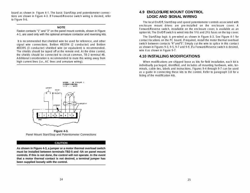
board as shown in Figure 4-1. The basic Start/Stop and potentiometer connec-tions are shown in Figure 4-3. If Forward/Reverse switch wiring is desired, referto Figure 9-6.
NOTEFaston contacts "1" and "2" on the panel mount controls, shown in Figure4-1, are used only with the optional armature contactor and reversing kits.
It is recommended that shielded wire be used for reference, and othersignal wire connections. Belden #83394 (2 conductor) and Belden#83395 (3 conductor) shielded wire (or equivalent) is recommended.The shields should be taped off at the remote end. At the drive control,the shields should be connected to circuit common, TB-2 terminal #8.Additional consideration is recommended to route this wiring away fromhigh current lines (i.e., AC lines and armature wiring).
Figure 4-3.Panel Mount Start/Stop and Potentiometer Connections
CAUTION
As shown in Figure 4-3, a jumper or a motor thermal overload switchmust be installed between terminals TB2-5 and -5A on panel mountcontrols. If this is not done, the control will not operate. In the eventthat a motor thermal contact is not desired, a terminal jumper hasbeen supplied loosely with the control.
25

26 27
SECTION 5OPERATION & STARTUP PROCEDURE
5.1 INTRODUCTIONThis section describes the startup procedure for the control and the adjust-
ment of potentiometers that may be necessary for the application.
Read this section thoroughly to develop an understanding of the operationand logic incorporated into the control.
5.2 START-UP PROCEDURETo insure maximum efficiency with a minimum amount of delay in production,
factory start-up assistance by a factory engineer is available. Contact the facto-ry to make arrangements.
CAUTION
The following start-up instructions are intended only as a guide andshould be clearly understood by the responsible installation per-sonnel before proceeding with them.
5.2.1 Pre-Start Equipment ChecksBefore starting the control, all of the following pre-start conditions must be
met.
1. Insure that the control has been properly programmed for 120VAC or 240VACoperation as described in Paragraph 4.3.1.
2. Check that all the jumpers have been set correctly as described inParagraph 4.3.
3. Complete all the wiring procedures described in Paragraphs 4.7, 4.8, and 4.9.
After all of the above pre-start conditions have been satisfied, proceed to thestart-up procedure described below. This start-up procedure is equally applica-ble for the panel and enclosure mount controls.
5.2.2 Operation and Adjustment1. Turn the speed potentiometer extreme counterclockwise. Insure that the
remote disconnect is admitting AC power to the control.
2. Set the On/Off switch to the ON position. This will apply power to the control,but it will not start the motor. The run LED indicator light on the main controlboard will be off.
3. Set the Start/Stop switch to the START position to start the motor. The run LEDindicator light will illuminate.
WARNING
DO NOT ALLOW THE ADJUSTING SCREW DRIVER TO TOUCH ANY-THING OTHER THAN THE POTENTIOMETER WHILE THE CONTROLIS OPERATIVE. USE ONLY AN INSULATED SCREWDRIVER TO MIN-IMIZE THE HAZARDS OF ELECTRIC SHOCK.
Steps A and B describe, respectively, the potentiometer adjustment proce-dure for operation in the speed or torque (current) mode of control.
A. Adjustment Procedure for Operation in the Speed Mode:(1) Maximum Speed Adjustment—
(a.) Run the motor with the load applied.(b.) Turn the speed potentiometer on the operator control panel fully
clockwise.(c.) Adjust the potentiometer on the Main PC Board marked "MAX" to
set the maximum motor speed. This may be adjusted from approximately 70 - 115% of motor base speed. DO NOT EXCEED THE MOTOR NAMEPLATE MAXIMUM SPEED RATING.
(d.) Using a hand held tachometer or by visually observing machine operation, adjust "MAX" to the desired maximum setting.
(2)Minimum Speed Adjustment — (a.) Turn the speed potentiometer on the operator control panel fully
counterclockwise.(b.) Adjust the potentiometer on main PC board marked "MIN" to
desired lowest motor speed setting. This adjustment may be set at 0 - 30% of the maximum speed setting.
(3) IR Compensation Adjustment—(a.) IR Compensation is provided to overcome the motor's natural
tendency to slow down as the load increases. If the motor slows down excessively as it is loaded, the potentiometer marked "IR COMP" should be adjusted clockwise.
(b.) If the IR compensation is adjusted too far clockwise, the motor will begin to oscillate in speed or "hunt." If this pulsing of speed occurs,adjust the IR Compensation counterclockwise until the motor speed stabilizes.
B. Adjustment Procedure for Operation in the Torque (Current) Mode:(1)Turn the potentiometers on the main PC board marked "MAX", "MIN",
and "IR COMP" fully counterclockwise.(2)Start motor and turn torque potentiometer on operator control panel fully
counterclockwise.(3) Adjust the potentiometer on the main PC board marked "MIN" to a min-
imum torque level if desired.(4)Leave potentiometers marked "MAX" and "IR COMP" turned fully coun-
terclockwise.
28 29
NOTEOn the enclosure mount controls, the provided Start/Stop switch willspring back to a middle position after it has been placed in the STARTposition and released.This switch must be momentarily held in the STARTposition to start the motor.
Adjust the speed potentiometer slowly clockwise until rotation begins. If themotor rotates in the wrong direction, simply place the On/Off switch in the OFFposition, place the Start/Stop switch in the STOP position, lock out power at theremote disconnect, and exchange the A1 and A2 output leads to the motor. Onshunt wound motors, exchange the shunt field F+ and F- leads.
CAUTION
If backward rotation of the motor could damage the driven machine,then direction of motor rotation should be determined before con-necting the motor shaft to the load.
If the drive trips off, the motor will coast to a stop or fail to start. A drive trip offis usually caused by incorrect wiring. It also can be caused by either (1) a faultymotor or (2) a malfunctioning drive. Proceed to Basic Troubleshooting (Section 7,Paragraph 7.4)
4. With the motor rotating, adjust the speed potentiometer up and down. Checkthat the motor follows the speed reference.
5. The control can be stopped in one of two (2) ways as follows:
A. A coast stop is initiated by either placing the Start/Stop switch in the STOPposition or by removing the AC power at the local On/Off switch or at theremote disconnect. Once AC power is removed and then restored, theStart/Stop switch must be momentarily set to the START position to restartthe motor.
B. A faster coast stop can be accomplished by installing the dynamic brak-ing kit. The armature contactor kit or reversing kit is required in this appli-cation. Refer to Figures 9-4 through 9-7 and the instruction sheets provid-ed with the individual kits for installation information.
6. Three (3) customer adjustable potentiometers are located on the PC board asshown in Figure 4-1. These potentiometers have been preset. However, forproper operation in some applications, minor readjustments may be neces-sary.
Before making final adjustments, allow the motor to warm up for at least 15minutes. With the control driving a motor, do not exceed ten (10) degrees ofpotentiometer rotation per second. Clockwise adjustment will cause anincrease in the adjustment parameter.

7. After Steps A and B above are done, the potentiometer in the operator controlpanel may be used to adjust either:
A. Motor speed from the minimum to maximum speed setting if control is inthe speed regulation mode, or
B. Motor torque level from the minimum torque setting to the maximum torquelevel for the current range selected if the control has been set up as atorque control.
8. If a Forward/Reverse switch is being used, flip it several times to verify that themotor follows direction change commands. The motor must be completelystopped before each flip of the switch.
CAUTION
Attempting to reverse the motor direction while it is still rotating cancause equipment damage.
30 31
SECTION 6FUNCTIONAL DESCRIPTION
This section describes, in detail, the following circuits included in the control:
1. Power Bridge and Field Supply
2. Start/Stop Logic
3. Regulator Circuitry
4. Power Supplies
Throughout this section, reference to the schematic diagrams in Figures 9-8and 9-9 is recommended.
6.1 Power Bridge and Field SupplyThroughout this paragraph, refer to Figure 6-1.
Figure 6-1.Power Bridge Assembly
NOTEComponent designations in Figure 6-1, such as "D1" and "D2", are for ref-erence purposes only. They do not correspond to actual component des-ignations on the control.

2. Transistor Clamp Circuit - This releases the gate drives whenever the drive isin the start mode. This circuit provides three (3) important functions: (1) it pre-vents misfiring of the SCRs when power is first applied to the drive, (2) it pro-vides positive gate pulse suppression in the stop mode, and (3) it resets theinner current loop upon drive stop.
Figure 6-2.Panel Mount Start/Stop Logic
Figure 6-3.Enclosure Mount Start/Stop Logic
(see Figure 4-1 for contact locations on PC board)
The power bridge supplied in the control consists of an encapsulated SCRpower cube containing two (2) SCRs and three (3) diodes. The basic operationconsists of the following sequence.
When L1 is more positive with respect to L2, SCR1 is gated “on” at a particu-lar phase angle commanded by the drive regulator circuitry. Current then flowsfrom L1, through SCR1, the shunt resistor, the drive motor, diode D2, and back toL2. When L2 is more positive with respect to L1, SCR2 is gated “on”. Currentflows from L2, through SCR2, the shunt resistor, the drive motor, and back to L1through diode D1. This results in a positive current flow through the motor.
Diode D3 is called a “free wheeling” diode which insures continuity of the loadcurrent when the previously “fired” SCR becomes reverse biased. This diode alsohelps the SCR return to its blocking state.
Three functional details are shown in Figure 6-1 as follows:
1. Armature Voltage Feedback Signal - This signal is used in determiningwhen the correct drive operating speed (voltage) is reached as requiredby the operator speed potentiometer.
2. Current Feedback Signal - This signal provides current information to thedrive inner current loop.
3. Control Circuit Common - This is tied to the positive terminal of the powerbridge.
CAUTION
The control circuit common is floating and must never be tied toearth ground. Attempting this will cause equipment damage or fail-ure.
Figure 6-1 also shows the motor shunt field supply. Diodes D1, D2, D4 and D5form a single phase full wave uncontrolled rectifier bridge. This bridge producesa 200 VDC field voltage when operated at 240 VAC and a 100VDC field voltagewhen operated at 120 VAC. The motor shunt field supply rating is 1 amp.
6.2 START/STOP LOGICThe standard start/stop logic is shown in Figures 6-2 and 6-3.
When the START button is momentarily activated, a 24VDC signal is suppliedto Control Run Relay CRR. This energizes CRR, which closes a normally opencontact and seals in CRR. When this occurs, 24 VDC will then be present on thesignal labeled +24 VDC RUN. This voltage is then directed to two (2) places asfollows:
1. Speed Potentiometer Voltage Supply - The Run LED lights and a 10 volt ref-erence appears at the top of the speed potentiometer. This voltage is zenerregulated and protects the 24 volt supply if a potentiometer wire is shorted tocommon.
32 33

6.3 REGULATOR CIRCUITRYThroughout this paragraph, refer to Figure 6-4.The multi-loop regulator circuitry consists of an inner current loop and an outer
voltage (speed) loop.
Figure 6-4.Control Circuit Block Diagram
The inner loop current error amplifier is a proportional plus integral controllerhaving an integrating time constant of about 10 milliseconds. This amplifierreceives a current reference from the outer loop velocity error amplifier and a cur-rent feedback voltage. This feedback voltage is derived from the current scalingamplifier. This inverting type scaling amplifier has an adjustable gain whichallows the customer to adapt the maximum current level of the drive to the motor.
One other input to the inner current loop, only present in the stop mode, resetsthe current error amplifier. The current error amplifier output is a positive voltagewith an amplitude such that, when fed to the firing circuit, produces gate pulses.These gate pulses are at a phase angle that produces the armature currentrequested by the velocity error amplifier.
The outer loop velocity error amplifier is also a proportional integral controller.Its integrating time constant is about 0.22 seconds. There are three inputs to thisamplifier.
The first of these is the speed command. This command is the voltage at thewiper of the operator speed potentiometer passed through a T-filter which pro-vides a 2-3 second acceleration time.
The second input is the armature voltage feedback. The feedback level isadjustable to allow the customer to set the maximum motor speed to the appli-cation requirement. The feedback level is also scaled by jumper programmingfor a 180VDC motor (240VAC input), 90VDC motor (120VAC input) and is short-ed out when the drive is used as a current regulator.
The third input to this amplifier is the IR compensation input. It is used to com-pensate for the IR losses in the motor. It should also be noted that this amplifiercan be changed (by jumper programming) to have approximately a gain of one,when the drive is to be used as a current regulator.
The firing circuit consists of three parts: (1) a timing ramp circuit (2) a com-parator circuit, and (3) a gated 555 oscillator. The timing ramp is produced byallowing a capacitor to charge to 10 volts in 8.3 msec. This capacitor is reset tozero volts at every zero crossing. This ramp voltage is then compared to the out-put voltage of the current error amplifier. When the ramp voltage exceeds the cur-rent error voltage, the comparator then toggles to +15 volts. The 15-volt signalenables the 555 oscillator, producing a train of firing pulses to the SCRs about 40m sec wide and 800 m sec apart.
6.4 POWER SUPPLIESFour (4) power supplies are available. These supplies are +24VDC and
+15VDC. The power supply transformer is rated at 6VA. The transformer input isjumper programmable on the PC board for 240VAC or 120VAC input voltages.
34 35

SECTION 7MAINTENANCE AND TROUBLESHOOTING
7.1 IMPORTANT SAFEGUARDSAll work on the drive should be performed by personnel familiar with it and its
application. Before performing any maintenance or troubleshooting, read theinstructions and consult the system diagrams.
WARNING
MAKE SURE THAT ALL POWER SOURCES HAVE BEEN DISCON-NECTED BEFORE MAKING CONNECTIONS OR TOUCHING INTER-NAL PARTS. LETHAL VOLTAGES EXIST INSIDE THE CONTROL ANY-TIME INPUT POWER IS APPLIED, EVEN IF THE DRIVE IS IN A STOPMODE. A TURNING MOTOR GENERATES VOLTAGE IN THE DRIVEEVEN IF THE AC LINE IS DISCONNECTED. EXERCISE CAUTIONWHEN MAKING ADJUSTMENTS. WITH THE CONTROL DRIVING AMOTOR, DO NOT EXCEED TEN (10) DEGREES OF POTENTIOMETERROTATION PER SECOND. NEVER INSTALL OR REMOVE THE PCBOARD WITH POWER APPLIED TO THE CONTROL.
7.2 ROUTINE MAINTENANCEOnly minor adjustments should be necessary on initial startup, depending on
the application. In addition, some common sense maintenance needs to be fol-lowed.
KEEP IT CLEAN: The control should be kept free of dust, dirt, oil, causticatmosphere and excessive moisture.
KEEP IT COOL: The control should be located away from machines having ahigh ambient temperature. On panel mount controls, air flow across heatsinksmust not be restricted by other equipment within the enclosure.
KEEP CONNECTIONS TIGHT: The equipment should be kept away from highvibration areas that could loosen connections or cause chafing of wires. All inter-connections should be retightened at time of initial startup and at least every sixmonths.
WARNING
THE DC MOTOR MAY BE AT LINE VOLTAGE EVEN WHEN IT IS NOTIN OPERATION. THEREFORE, NEVER ATTEMPT TO INSPECT,TOUCH OR REMOVE ANY INTERNAL PART OF THE DC MOTOR(SUCH AS THE BRUSHES) WITHOUT FIRST MAKING SURE THATALL AC POWER TO THE CONTROL AS WELL AS THE DC POWER TOTHE MOTOR HAS BEEN DISCONNECTED.
36 37

The motor should be inspected at regular intervals and the following checksmust be made:
A. See that both the inside and outside of the motor are not excessively dirty.This can cause added motor heating, and therefore, can shorten motor life.
B. If a motor blower is used, make sure that the air passages are clean andthe impeller is free to rotate. If air filters are used, they should be cleanedat regular intervals or replaced if they are disposable. Any reduction incooling air will increase motor heating.
C. Inspect the commutator and brushes. Replace the brushes if needed.Make sure that the proper brush grade is used.
D. The motor bearing should be greased per the manufacturer’s instructionsas to type of grease and maintenance frequency. Over greasing can causeexcessive bearing heating and failure. Consult the instructions suppliedwith the motor for more details.
7.3 TROUBLESHOOTING OVERVIEWFast and effective troubleshooting requires well-trained personnel supplied
with the necessary test instruments as well as a sufficient stock of recommend-ed spare parts. Capable electronic technicians who have received training in thecontrol operation and who are familiar with the application are well qualified toservice this equipment.
7.3.1 Suggested TrainingA. Study the system instruction manual and control drawings.
B. Obtain practical experience during the system installation and in futureservicing.
C. Train in the use of test instruments.
7.3.2 Maintenance RecordsIt is strongly recommended that the user keeps records of downtime, symp-
toms, results of various checks, meter readings, etc. Such records will often helpa service engineer locate the problem in the minimum time should such servicesbe required.
7.3.3 General TroubleshootingThe most frequent causes of drive failure are:
A. Interconnect wire discontinuity, caused by a broken wire or loose connection.
B. Circuit grounding within the interconnections or the power wiring.
C. Mechanical failure at the motor.
DO NOT make adjustments or replace components before checking allwiring. Also monitor all indicator lights before proceeding with troubleshootingchecks, and check for blown fuses.
It should be noted that modern solid state electronic circuitry is highly reliable.Often problems which appear to be electrical are actually mechanical. It isadvised that the motor be checked in the event of any drive problems. Refer tothe motor owner’s manual for maintenance and repair procedures.
7.3.4 Notes for a Troubleshooting TechnicianA minimum knowledge of system operation is required, but it is necessary to
be able to read the system schematics and connection diagrams.
An oscilloscope (Tektronix 214 or equivalent) may be needed to locate prob-lem areas and to make adjustments. However, the majority of problems can besolved by using a multimeter and by parts substitution.
Multimeters having a sensitivity of 1000 ohms per volt on DC or more are rec-ommended, such as a Triplett Model 630, a Simpson Model 260, or equivalent.
WARNING
WHEN A TEST INSTRUMENT IS BEING USED, CARE MUST BETAKEN TO INSURE THAT ITS CHASSIS IS NOT GROUNDED EITHERBY A GROUNDING PLUG CONNECTION OR BY ITS CASE BEING INCONTACT WITH A GROUNDED SURFACE. EXTREME CARE MUSTBE TAKEN WHEN USING THE OSCILLOSCOPE SINCE ITS CHASSISWILL BE ELECTRICALLY HOT TO GROUND WHEN CONNECTED TOTHE CONTROL SYSTEM.
7.4 BASIC TROUBLESHOOTINGThis paragraph contains a basic list of symptoms of an improperly functioning
control. Included in the list are possible causes and corrective measures for eachsymptom described.
WARNING
BEFORE PROCEEDING WITH ANY MAINTENANCE OR TROU-BLESHOOTING ACTIVITY, ALL POWER SOURCES MUST BE DIS-CONNECTED AS DESCRIBED IN PARAGRAPH 7.1.
CONTROL APPEARS TO BE DEAD:
A. ON PANEL MOUNT CONTROLS: Terminals TB2-5 and -5A are notjumpered together - install either a motor thermal overload switch or a ter-minal jumper (supplied loosely with control).
B. No AC power - apply AC power.
C. Blown line fuses - replace line fuses.38 39

D. Loose connections - turn off AC power and tighten connections.
E. Control incorrectly wired - recheck all wiring.
F. Defective power module, Start/Stop switch, component on regulator PCboard, or relay - replace bad components as required.
G. Speed potentiometer set to zero - slowly advance from zero to beginmotor rotation.
LINE FUSES BLOW OR MAIN CIRCUIT BREAKER TRIPS WHENAPPLYING AC POWER:
A. Power module, field supply diode or suppressor shorted, or a short toground is present - locate and remove short.
B. Control is wired to AC voltage exceeding control rating - rewire control toproper AC voltage or use step-down transformer.
FUSES BLOW WHEN SPEED POTENTIOMETER IS ADVANCEDFROM ZERO:
A. Motor is overloaded - reduce load as required.
B. Motor is defective - consult motor instruction manual and repair or replacemotor as required.
ACCEL/DECEL RAMP IS MUCH LONGER THAN EXPECTED:A. Motor overloaded/overhauling - reduce load or apply optional braking kit.
MOTOR DOES NOT REACH FULL SPEED:A. Motor is overloaded - correct overload condition.
B. Maximum Speed potentiometer (MAX) is set too low - adjust MAX poten-tiometer clockwise.
C. Low AC line voltage (more than 10% below nominal) - check AC line volt-age and correct.
D. Current limit level jumper (J2) in wrong position - reprogram as describedin Paragraph 4.3.3.
E. Feedback jumper (J3) in wrong position - reprogram as described in Paragraph 4.3.
F. Speed/Torque jumper (J1) in wrong position - reprogram as described inParagraph 4.3.1.
G. Defective power module - replace as required.
H. Motor brushes worn — replace as specified in motor instruction manual.
40
MOTOR RUNS IN WRONG DIRECTION:A. The A1 and A2 output leads to the motor are incorrectly wired - exchange
these leads.B. On shunt wound motors only, the shunt field F+ and F- leads are incorrectly
wired - exchange these leads.C. The Forward/Reverse switch (if used) is in the wrong position - change this
position.
CAUTION
The motor must be completely stopped before it is started in oppo-site rotation. Attempting to reverse the motor direction while it is stillrotating can cause equipment damage.
MOTOR DOES NOT MAINTAIN SPEED UNDER LOAD:A. IR COMP potentiometer is set too low - adjust clockwise as described in
Paragraph 5.2.2.
B. Motor is overloaded - correct overload condition.
C. Speed/Torque jumper (J1) in wrong position - reprogram as described inParagraph 4.3.1.
D. Defective component on regulator PC board - replace as required.
E. Current limit level jumper (J2) in wrong position - reprogram as describedin Paragraph 4.3.3.
F. Motor brushes worn - replace as specified in motor instruction manual.
MOTOR IS UNSTABLE OR OSCILLATES:A. IR COMP potentiometer set too high - adjust IR COMP potentiometer coun-
terclockwise until the motor speed stabilizes without oscillating.
B. Defective motor - consult motor instruction manual and repair or replace asrequired.
C. Load is loosely coupled to motor or misaligned - check and correct loadcoupling.
D. Loose wire connections - tighten connections (to motor).
E. Defective component on regulator PC board - replace as required.
MOTOR DOES NOT COME TO FULL STOP:A. Minimum speed potentiometer (MIN) is set too high - readjust as described
in Paragraph 5.2.2.
B. Defective speed potentiometer, component on regulator PC board,Start/Stop switch, or power module - replace as required.
41
42 43
SECTION 8ORDERING SPARE PARTS
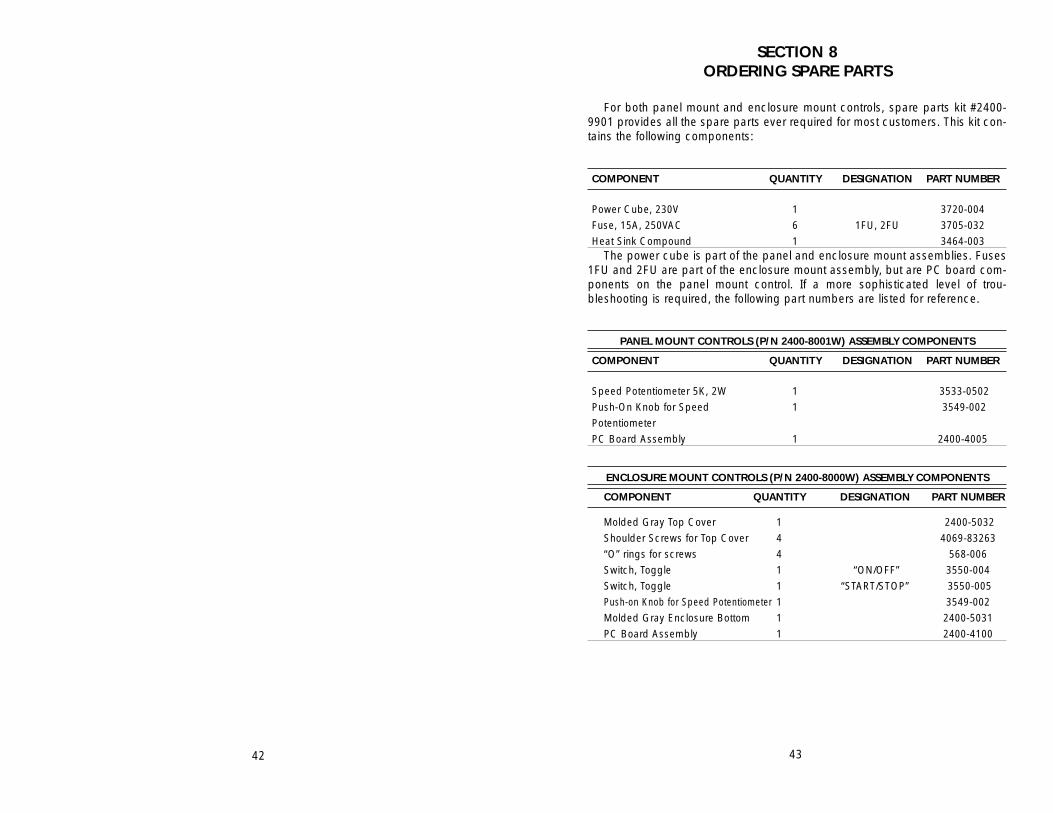
For both panel mount and enclosure mount controls, spare parts kit #2400-9901 provides all the spare parts ever required for most customers. This kit con-tains the following components:
COMPONENT QUANTITY DESIGNATION PART NUMBER
Power Cube, 230V 1 3720-004
Fuse, 15A, 250VAC 6 1FU, 2FU 3705-032
Heat Sink Compound 1 3464-003The power cube is part of the panel and enclosure mount assemblies. Fuses
1FU and 2FU are part of the enclosure mount assembly, but are PC board com-ponents on the panel mount control. If a more sophisticated level of trou-bleshooting is required, the following part numbers are listed for reference.
PANEL MOUNT CONTROLS (P/N 2400-8001W) ASSEMBLY COMPONENTS
COMPONENT QUANTITY DESIGNATION PART NUMBER
Speed Potentiometer 5K, 2W 1 3533-0502
Push-On Knob for Speed 1 3549-002
Potentiometer
PC Board Assembly 1 2400-4005
ENCLOSURE MOUNT CONTROLS (P/N 2400-8000W) ASSEMBLY COMPONENTS
COMPONENT QUANTITY DESIGNATION PART NUMBER
Molded Gray Top Cover 1 2400-5032
Shoulder Screws for Top Cover 4 4069-83263
“O” rings for screws 4 568-006
Switch, Toggle 1 “ON/OFF” 3550-004
Switch, Toggle 1 “START/STOP” 3550-005
Push-on Knob for Speed Potentiometer 1 3549-002
Molded Gray Enclosure Bottom 1 2400-5031
PC Board Assembly 1 2400-4100

PANEL AND ENCLOSURE MOUNT CONTROLS PC BOARD COMPONENTS
COMPONENTQUANTITY DESIGNATION PART NUMBER
Capacitors - Consult Factory with the Value and Board Designation
Diodes: 1A, 200V 6 D1-D5, D8 1N4003
10mA, 75V 9 D6,D7,D9-D12, 1N914
D15-D17
3A, 600V 2 D13, D14 4020-D030X06
LED 1 “RUN” 4030-500
Diodes, Zener: 15V 2 DZ1,DZ2 1N4744A
10V 1 DZ3 1N4740A
12V 1 DZ4 1N4742A
Operational Amplifier 2 L1, L2 4041-0358
Timing Circuit 1 L3 4041-0555
Potentiometers : 5K 2 “MIN”, “IR COMP” 3545-053
500K 1 “MAX” 3545-055
R-C Network:
0.1 mF, 47 ohm 1 RC1 3084-118
Relay 1 CRR 3520-240
Resistors - Consult Factory with Value and Board designation.
Resistor, Shunt:
.01 ohms, 3W, 5% 1 R19 0916-8R01-005
Terminal blocks: 7-position 1 TB1 3792-1607
9-position 1 TB2 3792-1509
Transformer 1 T1 3082-436
Transistors 4 Q1-Q4 0991-003N
Varistor 1 QVR1 4017-2515
44 45
SECTION 9SUPPLEMENTARY TECHNICAL INFORMATION
Table 9-1Control Standard Connection Scheme
Terminal Blocks TB1 and TB2
TB1 (PANEL AND ENCLOSURE MOUNT CONTROLS)
L1, L2 Incoming AC power
F+, F- Shunt field connections
A1, A2 DC Motor connections
X Connected by link to A1 (also, F- is connected by link to A2).
Do not remove either link unless the optional armature
contactor or reversing kits are being installed.
NOTEIf TB1 has terminals F1 and F2 instead of F+ and F-, the F1 and F2 ter-minals correspond respectively, to F+ and F-.
TB2 (PANEL MOUNT CONTROLS ONLY)
1,2 Terminals for optional reversing kit toggle switch. Also, TB2-1
is jumpered to TB2-5 when armature contactor kit is used.
3, 4 N.O. Start contact
4, 5A N.C. Stop contact
5, 5A N.C. Motor thermal contact, (if required). Jumper TB2-5 to
-5A if thermal contact is not used.
6 CW side of speed potentiometer
7 Wiper contact of speed potentiometer
8 CCW side of speed potentiometer (Min Speed)
Table 9-2Customer Jumper Programming Chart (filled out by customer)
JUMPER GROUP POSITION AT STARTUP
J1
J2
J3
JA& B
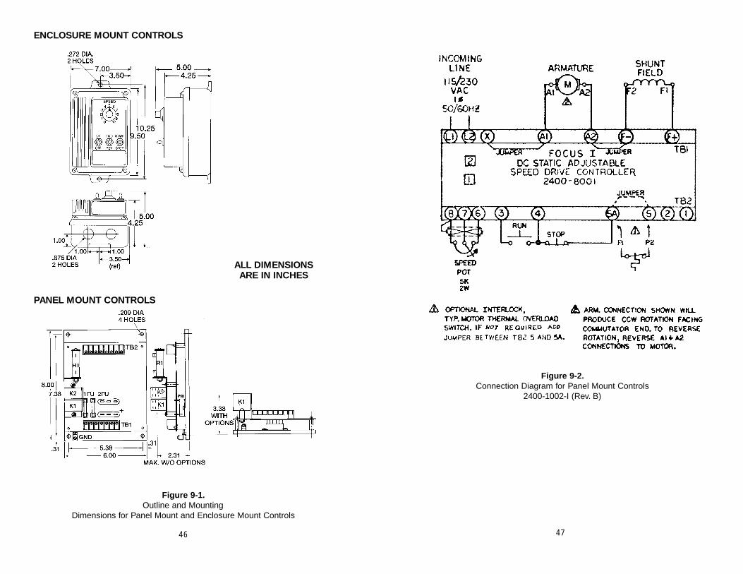
46 47
Figure 9-1.Outline and Mounting
Dimensions for Panel Mount and Enclosure Mount Controls
Figure 9-2.Connection Diagram for Panel Mount Controls
2400-1002-I (Rev. B)
ENCLOSURE MOUNT CONTROLS
ALL DIMENSIONS ARE IN INCHES
PANEL MOUNT CONTROLS
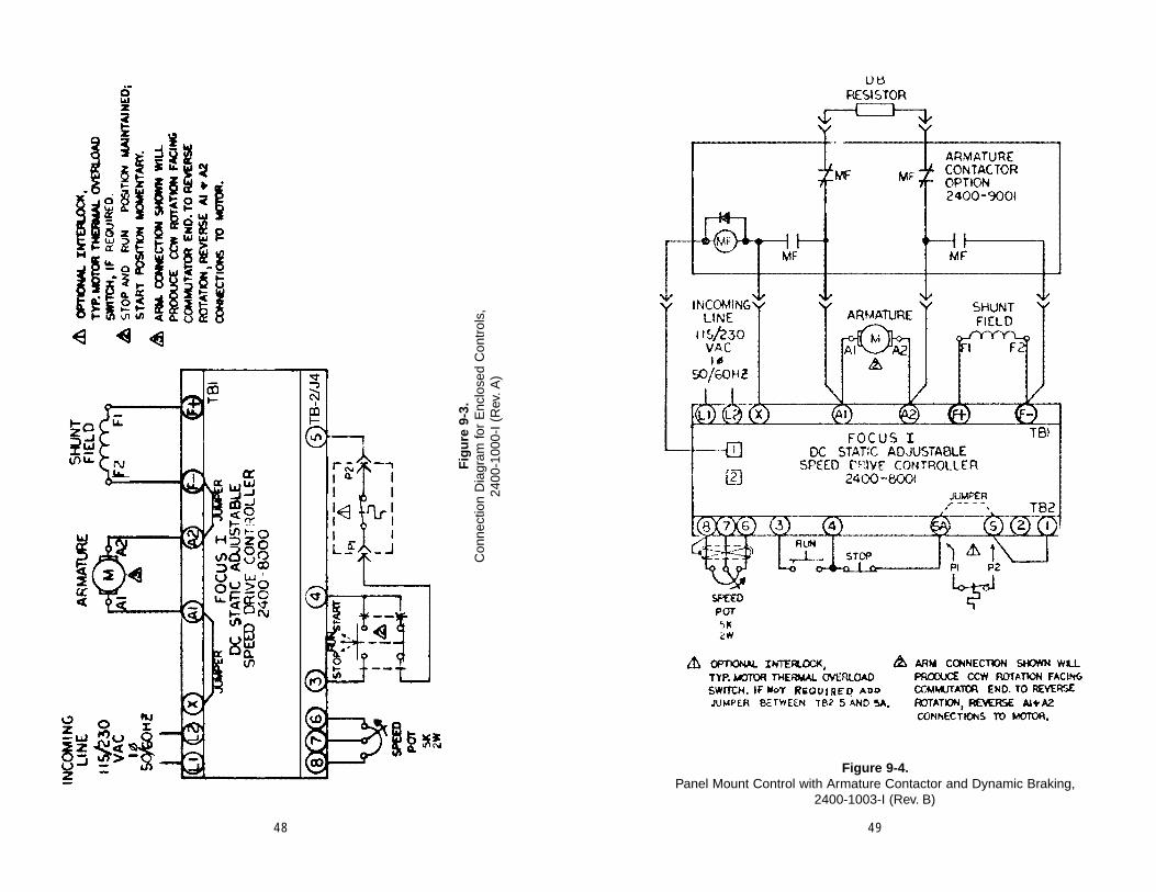
48 49
Fig
ure
9-3
.C
onne
ctio
n D
iagr
am fo
r E
nclo
sed
Con
trol
s,
2400
-100
0-I
(Rev
.A)
Figure 9-4.Panel Mount Control with Armature Contactor and Dynamic Braking,
2400-1003-I (Rev. B)

50 51
Figure 9-5.Enclosed Control with Armature Contactor and Dynamic Braking,
2400-1001-I, (Rev. A)
Figure 9-6.Panel Mount Control with Reversing and Dynamic Braking,
2400-1005-I ( Rev. B)
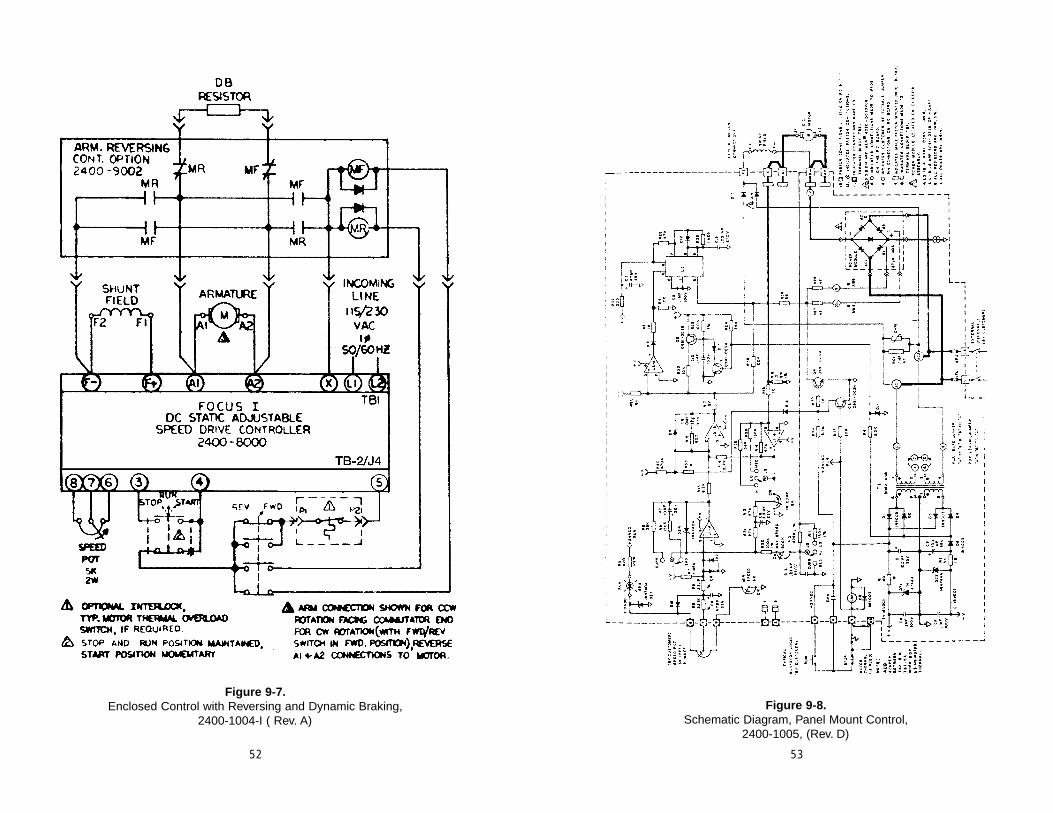
52
Figure 9-7.Enclosed Control with Reversing and Dynamic Braking,
2400-1004-I ( Rev. A)
53
Figure 9-8.Schematic Diagram, Panel Mount Control,
2400-1005, (Rev. D)

SECTION 10BASIC APPLICATION INFORMATION
10.1 BASIC MECHANICSTwo (2) basic mechanical parameters, torque and horsepower, must be com-
pletely understood to properly apply DC drives.
10.1.1 TorqueTorque is a force applied that tends to produce rotation. Torque (force) with-
out rotation is called static torque, since no motion is produced.
Torque is measured in lb-in or lb-ft. It is the product of the force in pounds (lb)x the distance in inches (in) or feet (ft) from the center of the point of apparentrotation. Figure 10-1 shows 120 lb-in (12 inches x 10 lb) or 10 lb-ft of torque.
Figure 10-1.Example of 10 lb-ft Applied Torque
Because most power transmission is based upon rotating elements, torque isimportant as a measurement of the effort required to produce work.
10.1.2 HorsepowerHorsepower is a measure of the rate at which work is being done. When a
force is applied in a manner that produces motion, work can be measured. One(1) horsepower (HP) is defined as the force required to lift 33,000 lbs. one foot inone minute.
10.2 TORQUE VS. HORSEPOWERA simple formula exists that relates torque and horsepower to each other. This
formula is:
Torque (lb-ft) x Speed (RPM)
Horsepower = 5250
10.3 MATCHING THE DRIVE TO THE MACHINEThe application of an adjustable speed drive to a machine is a mechanical,
rather than an electrical problem. When applying the drive, the speed, torque,and horsepower characteristics developed at the motor shaft must be consid-ered. These must meet or exceed the torque and horsepower requirements of themachine being driven.
Figure 9-9.Schematic Diagram, Enclosure Mount Control,
2400-1501-I, (Rev. -)54 55
FORCE10 LBS.
12 "
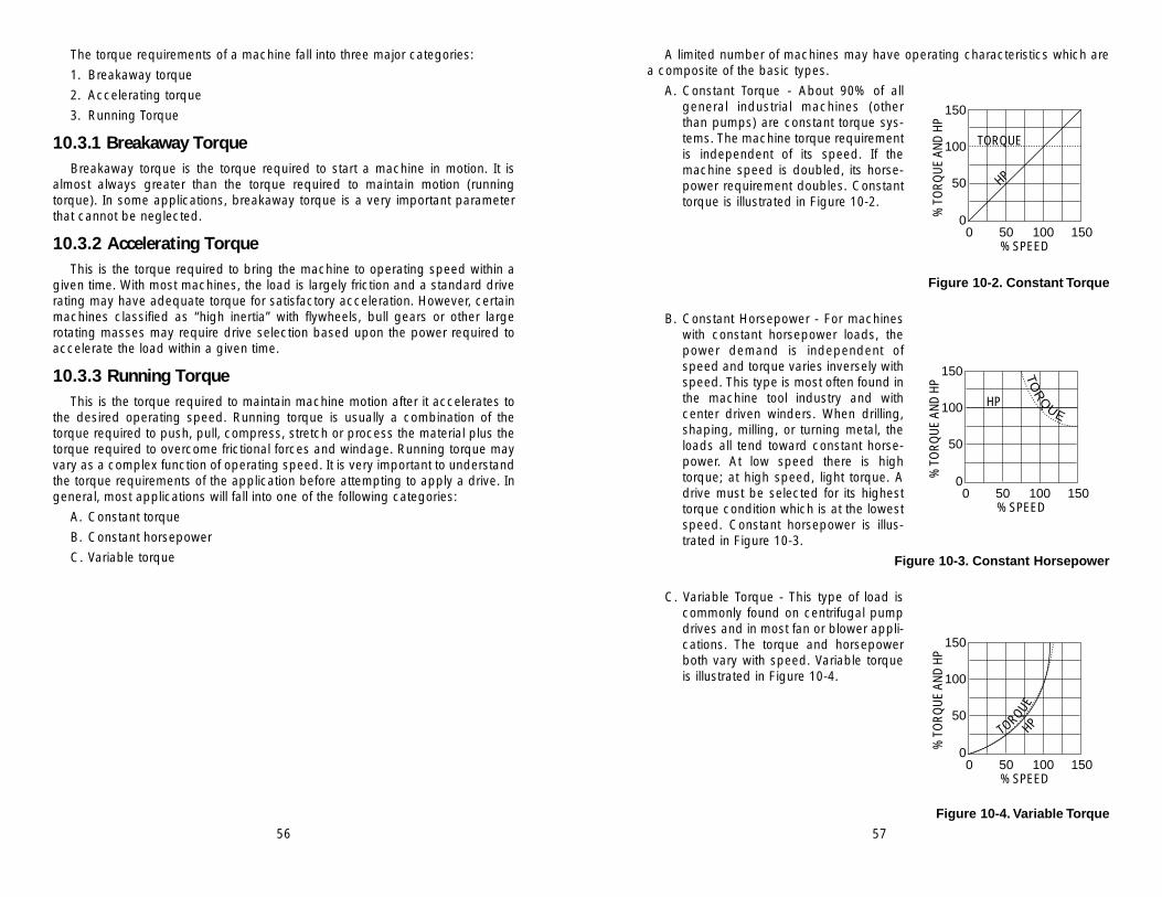
A limited number of machines may have operating characteristics which area composite of the basic types.
A. Constant Torque - About 90% of allgeneral industrial machines (otherthan pumps) are constant torque sys-tems. The machine torque requirementis independent of its speed. If themachine speed is doubled, its horse-power requirement doubles. Constanttorque is illustrated in Figure 10-2.
Figure 10-2. Constant Torque
B. Constant Horsepower - For machineswith constant horsepower loads, thepower demand is independent ofspeed and torque varies inversely withspeed. This type is most often found inthe machine tool industry and withcenter driven winders. When drilling,shaping, milling, or turning metal, theloads all tend toward constant horse-power. At low speed there is hightorque; at high speed, light torque. Adrive must be selected for its highesttorque condition which is at the lowestspeed. Constant horsepower is illus-trated in Figure 10-3.
Figure 10-3. Constant Horsepower
C. Variable Torque - This type of load iscommonly found on centrifugal pumpdrives and in most fan or blower appli-cations. The torque and horsepowerboth vary with speed. Variable torqueis illustrated in Figure 10-4.
Figure 10-4. Variable Torque
56 57
The torque requirements of a machine fall into three major categories:
1. Breakaway torque
2. Accelerating torque
3. Running Torque
10.3.1 Breakaway TorqueBreakaway torque is the torque required to start a machine in motion. It is
almost always greater than the torque required to maintain motion (runningtorque). In some applications, breakaway torque is a very important parameterthat cannot be neglected.
10.3.2 Accelerating TorqueThis is the torque required to bring the machine to operating speed within a
given time. With most machines, the load is largely friction and a standard driverating may have adequate torque for satisfactory acceleration. However, certainmachines classified as “high inertia” with flywheels, bull gears or other largerotating masses may require drive selection based upon the power required toaccelerate the load within a given time.
10.3.3 Running TorqueThis is the torque required to maintain machine motion after it accelerates to
the desired operating speed. Running torque is usually a combination of thetorque required to push, pull, compress, stretch or process the material plus thetorque required to overcome frictional forces and windage. Running torque mayvary as a complex function of operating speed. It is very important to understandthe torque requirements of the application before attempting to apply a drive. Ingeneral, most applications will fall into one of the following categories:
A. Constant torque
B. Constant horsepower
C. Variable torque
150
0
50
100
0 50 100 150% SPEED
% T
OR
QU
E AN
D H
P
TORQUE
HP
150
0
50
100
0 50 100 150% SPEED
% T
OR
QU
E AN
D H
P
HP
TO
RQ
UE
150
0
50
100
0 50 100 150% SPEED
% T
OR
QU
E AN
D H
P
TORQUEHP

10.4 DC DRIVE CHARACTERISTICS
10.4.1 Constant Torque ApplicationsArmature voltage controlled DC drives are constant-torque drives. They are
capable of providing rated torque at any speed between zero and the base(rated) speed of the motor. Horsepower varies in direct proportion to speed, and100% rated horsepower is developed only at 100% rated motor speed with ratedtorque.
10.4.2 Constant Horsepower ApplicationsA. Armature Controlled DC Drives - Certain applications require constant
horsepower over a specified speed range. Since an armature voltage con-trolled DC drive has constant torque characteristics, the drive must beoversized to handle these applications. A drive required to deliver constanthorsepower over a 2:1 speed range has to be rated at twice the requiredhorsepower since it only develops 50% of its rated horsepower at halfspeed. The horsepower rating required for any constant torque drive oper-ated in a constant horsepower application can be easily calculated as fol-lows. Multiply the desired horsepower by the ratio of the speed range overwhich horsepower must remain constant. If 5HP is required over a 2:1range, an armature only controlled drive rated for 10 horsepower (5 HPx 2)would be required.
B. Field Controlled DC Drives - Another characteristic of a shunt-wound DCmotor is that a reduction in field voltage to less than the design ratingresults in an increase in speed for a given armature voltage. It is importantto note, however, that this results in a higher armature current for a givenmotor load. A simple method of accomplishing this is by inserting a resis-tor in series with the field voltage source. This may be useful for achievingan ideal motor speed for the application. An optional, more sophisticatedmethod uses a variable voltage field regulator. This provides coordinatedautomatic armature and field voltage control for extended speed range inconstant HP applications. The motor is armature voltage controlled for con-stant torque-variable HP operation to base speed. It is then transferred tofield control for constant HP-variable torque operation to maximum speed.This is illustrated in Figure 10-5.
Figure 10-5.Motor Armature Voltage Control
and Field Control
10.5 OTHER MECHANICAL CONSIDERATIONS
10.5.1 Constant Torque Speed RangeWhen a DC drive is operated continuously at low speed and rated torque,
motor heating problems may be encountered. At reduced speeds, the motorinternal cooling fan is less effective and overheating occurs if the motor remainsfully loaded. A typical self ventilated DC motor continuous torque rating as afunction of speed is shown in Figure 10-6.
When continuous operation is required at rated torque and reduced speed,supplemental motor ventilation such as a motor mounted blower or separate ven-tilation duct must be supplied. An oversized motor (one that does not have toproduce rated torque) or a totally enclosed non-ventilated (TENV) motor may alsobe used in these situations.
10.5.2 Torque LimitationsMost adjustable speed drives feature a torque limiter to protect the drive and
the machine from torque overloads. The torque limiter (current limit) is normallyadjustable to 150% of rated torque to allow extra momentary torque for break-away, acceleration or cyclic overloads. Most drive systems are capable of sus-taining the 150% torque overload for 1 minute or less.
10.5.3 Duty CycleCertain applications may require continuous reversals, long acceleration
times at high torque due to inertia loads, frequent high rate acceleration or cyclicoverloads. These may result in severe motor heating if not considered in theselection of the drive. Most drives with 150% overload capability operate suc-cessfully if there are compensating periods of operation where motor tempera-tures can be normalized.
10.5.4 Overhauling LoadsIn some applications, process tension differences, downhill loads, or machine
inertia may cause the driven machine to overhaul the drive motor. In these appli-cations, the DC motor must provide holdback torque to brake the load. A regen-erative drive is usually required in theseapplications.
Figure 10-6.Constant Torque Speed Range
58 59
25
0
50
100
0 50 100 150 200% RATED BASE SPEED
% R
ATED
HP
% T
OR
QU
E 75
TORQUE
HP
0
50
100
0 50 100% SPEED
% R
ATED
TO
RQ
UE
CAUTION
The above formulas for calculating horsepower do not include anyallowance for machine function windage or other factors.These fac-tors must be considered when selecting a drive for a machine appli-cation.
E. For Fans and Blowers
HP = CFM x Pressure (lb/ft2)33,000 x (Eff. of Fan)
Effect of speed on HP:
HP = K1 (RPM)3 - Horsepower varies as the 3rd power of speed
T = k1 (RPM)2 Torque varies as the 2nd power of speed
Flow = k3 (RPM) - Flow varies directly as the speed.
HP = CFM x Pressure (lb/In2)229 x (Eff. of Fan)
HP = CFM x (Inches of Water Gauge)6356 x (Eff. of Fan)
F. For Pumps
HP = GPM x Head (Ft) x (Specific Gravity)3960 x (Efficiency of Pump)
Specific gravity of water = 1.0
1 cu. ft. per sec. = 448 GPM
1 PSI = A head of 2.309 ft. for water weighing
62.36 lbs./ft.3 and 62oF
Displacement pump efficiency:
Displacement pumps may vary between 50% and 80% efficiency, depending on size of pumps.
Centrifugal pump efficiency:
500 to 1000 gal. per min. = 70% to 75%
1000 to 1500 gal. per min. = 75% to 80%
Larger than 1500 gal. per min. = 80% to 85%
10.6.2 Inertia (WK2)The factor WK2 is the weight (lb) of an object multiplied by the square of the
radius of gyration (K). The unit measurement of the radius of gyration isexpressed in feet.
60 61
10.6 MOTOR APPLICATION FORMULAS
10.6.1 Calculating HorsepowerOnce the machine torque requirement is determined, horsepower can be cal-
culated using the formula:
HP = T x N5250
where,
HP = Horsepower
T = Torque, (lb-ft)
N = Base speed of motor (rpm)
If the calculated horsepower falls between standard available motor ratings,select the higher available horsepower rating. It is good practice to allow somemargin when selecting the motor horsepower.
For many applications, it is possible to calculate the horsepower requiredwithout actually measuring the torque required. The following useful formulas willhelp:
A. For Conveyors
HP (Vertical) = Weight (lb) x Velocity (FPM)33,000
HP (Horizontal) = Weight (lb) x Velocity (FPM) x Coef. of Friction33,000
B. For Web Transport Systems and Surface Winders
HP = Tension (lb) x Velocity (FPM)33,000
Note that the tension value used in this calculation is the actual web tensionfor surface winder applications, but it is the tension differential (downstream ten-sion - upstream tension) for sectional drives.
C. Center Winders (Armature Control Only)
HP = Tension (lb) x Line Speed (FPM) x Buildup33,000 x Taper
D. Center Winders (Field Control)
If Taper x Field Range > Buildup
HP = Tension (lb) x Line Speed (FPM)33,000
If Taper x Field Range < Buildup
HP = Tension (lb) x Line Speed (FPM) x Buildup33,000 x Taper x Field Range

62
Table 10-1Inertia of Steel Shafting (per inch of length)
DIAM. (IN) WK2 (=-LB -FT2) DIAM. (IN) WK2 (=LB -FT2)
3/4 .00006 10-1/2 2.351 .0002 10-3/4 2.581-1/4 .0005 11 2.831-1/2 .001 11-1/4 3.091-3/4 .002 11-1/2 3.38
2 .003 11-3/4 3.682-1/4 .005 12 4.002-1/2 .008 12-1/4 4.352-3/4 .011 12-1/2 4.72
3 .016 12-3/4 5.113-1/2 0.029 13 5.583-3/4 0.038 13-1/4 5.96
4 0.049 13-1/2 6.424-1/4 0.063 13-3/4 6.914-1/2 0.079 14 7.42
5 0.120 14-1/4 7.975-1/2 0.177 14-1/2 8.54
6 0.250 14-3/4 9.156-1/4 0.296 15 9.756-1/2 0.345 16 12.596-3/4 0.402 17 16.04
7 0.464 18 20.167-1/4 0.535 19 25.037-1/2 0.611 20 30.727-3/4 0.699 21 37.35
8 0.791 22 44.998-1/4 0.895 23 53.748-1/2 1.00 24 63.718-3/4 1.13 25 75.02
9 1.27 26 87.769-1/4 1.41 27 102.069-1/2 1.55 28 118.049-3/4 1.75 29 135.83
10 1.93 30 155.5510-1/4 2.13 - -
For solid or hollow cylinders, inertia may be calculated by using the equationsgiven here.
The inertia of solid steel shafting per inch of shaft length is given in Table10-1. To calculate hollow shafts, take the difference between the inertia values forthe O.D. and I.D. For shafts of materials other than steel, multiply the value forsteel by the appropriate factor given in Table 10-2.
Table 10-2Density Factors
SHAFT MATERIAL FACTOR
Rubber .121Nylon .181
Aluminum .348Bronze 1.135
Cast Iron .922Steel 1.00
The inertia of complex, concentric rotating parts may be calculated by break-ing the part up into simple rotating cylinders, calculating their inertias and sum-ming their values, as shown in the following diagram.
63
SOLID D
L
HOLLOWL
WK2 = .000681 p LD4
D1
D2
3
WK2 = .000681 p L (D24 - D14)WK2 = lb. ft.2
D1D1D1 and L = in.p = lb./in.3
p (aluminum) = .0924p (bronze) = .320
p (cast iron) = .260p (steel) = .282
p (paper) = .0289
= + +
WK2TOT = WK2
1 + WK22 + WK2
3

10.6.3 WK2 of Rotating ElementsIn practical mechanical systems, all the rotating parts do not operate at the
same speed. The WK2 of all moving parts operating at each speed must bereduced to an equivalent WK2 at the motor shaft, so that they can all be addedtogether and treated as a unit, as follows:
Equivalent WK2 = WK2 ( N )2
Nm
Where
WK2, =inertia of the moving partN = speed of the moving part (RPM)Nm = speed of the driving motor (RPM)
When using speed reducers, and the machine inertia is reflected back to themotor shaft, the equivalent inertia is equal to the machine inertia divided by thesquare of the drive reduction ratio.
10.6.4 WK2 of Linear MotionNot all driven systems involve rotating motion. The equivalent WK2 of lineari-
ly moving parts can also be reduced to the motor shaft speed as follows:
Equivalent WK2 = W (V)239.5 ( Nm)2
Where,
W = weight of load (lb)V = linear velocity of rack and load or conveyor and load (FPM)Nm = speed of the driving motor (RPM)
This equation can only be used where the linear speed bears a continuousfixed relationship to the motor speed, such as a conveyor.
10.7 ELECTRICAL FORMULASOhms Law:
Amperes = Volts Ohms = Volts Ohms Amperes
Volts = Amperes x OhmsPower in DC Circuits:Watts = Volts X Amperes
Horsepower = Volts x Amperes746
Kilowatts = Volts x Amperes1000
64 65
Kilowatt-Hours = Volts x Amperes x Hours1000
Power in AC Circuits:Kilovolt - Amperes (kVA)
kVA (Single-Phase) = Volts x Amperes1000
kVA (Three-Phase) = Volts x Amperes x 1.73 1000
Kilowatts (kW)
kW (Single-Phase) = Volts x Amperes x Power Factor1000
kW (Three-Phase) = Volts x Amperes x Power Factor x 1.73 1000
Power Factor = Kilowatts Kilovolts x Amperes
10.8 OTHER USEFUL FORMULAS1KW = 56.88 BTU/MIN
1HP = 0.7457kW
= 550 lb-ft per sec
= 33,000 lb-ft per min
= 2545 BTU per hour
TEMPERATURE CONVERSIONDegrees C = (Degrees F-32) x 5/9
Degrees F = (Degrees C x 9/5) + 32

APPENDIX AGLOSSARY
Constant HP Load - A load requiring high torque at low speeds, low torque athigh speeds, and thus constant horsepower at any speed.
Constant Torque Load - A load requiring the same amount of torque at lowspeed as at high speed. Torque remains constant throughout the speedrange, and the horsepower increases and decreases in direct proportion tothe speed.
CRR - Control run relay.
Horsepower - A measure of the rate at which work is being done. One (1)horsepower (HP) is defined as the force required to lift 33,000 lbs. one foot inone minute.
IR Compensation - An adjustment that overcomes the natural tendency for amotor to decelerate with increasing load.
LED - Light emitting diode.
Non-Regenerative Drive - One which rotates the DC motor in only one direc-tion to supply rotational energy or torque into the load.
Overhauling Load - A load such as a process tension difference, a downhillload or machine inertia that requires the motor to provide holdback torque tobrake the load. A regenerative drive or energy absorber kit is usually requiredin these applications.
Regenerative Drive - One which can both deliver and remove electrical ener-gy to or from a motor. In this manner, rotational mechanical energy can be sup-plied to or be removed from a load.
SCR - Silicon controlled rectifier.
TENV - Totally Enclosed Non-Ventilated.
Torque - A force applied that tends to produce rotation. Breakaway torque is thetorque required to start a machine in motion. Accelerating torque is the torquerequired to bring the machine to operating speed within a given time. Runningtorque is the torque required to maintain machine motion after it acceleratesto the desired operating speed.
Variable Torque Load - A load requiring much lower torque at low speedsthan at high speeds. Horsepower varies approximately as the cube of thespeed, and the torque varies approximately as the square of the speed.
66 67