FM DISTRIBUTION FOR MOTORWAYS AND TUNNELS - TRX...
6
FM DISTRIBUTION FOR MOTORWAYS AND TUNNELS
Transcript of FM DISTRIBUTION FOR MOTORWAYS AND TUNNELS - TRX...

FM DISTRIBUTION FOR MOTORWAYS AND TUNNELS

As compared to the traditional analog systems, our innovative solution for FM transmission allows considerable cost reductions in terms of equipment, system complexity and management costs, at the same time providing a high-efficiency infrastructure and an easy scalability of the whole network (see diagram).
Head station: one single station can manage the whole network.
Transmission stations: extremely compact and modular (as many as needed in the network)
ADVANTAGES IF COMPARED TO A “TRADITIONAL” SYSTEM
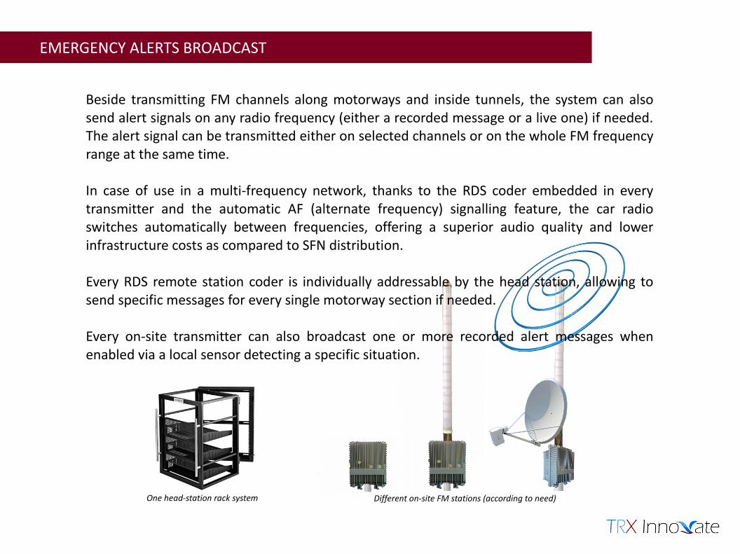
Beside transmitting FM channels along motorways and inside tunnels, the system can also send alert signals on any radio frequency (either a recorded message or a live one) if needed. The alert signal can be transmitted either on selected channels or on the whole FM frequency range at the same time.
In case of use in a multi-frequency network, thanks to the RDS coder embedded in every transmitter and the automatic AF (alternate frequency) signalling feature, the car radio switches automatically between frequencies, offering a superior audio quality and lower infrastructure costs as compared to SFN distribution.
Every RDS remote station coder is individually addressable by the head station, allowing to send specific messages for every single motorway section if needed.
Every on-site transmitter can also broadcast one or more recorded alert messages when enabled via a local sensor detecting a specific situation.
EMERGENCY ALERTS BROADCAST
One head-station rack system Different on-site FM stations (according to need)

The head station manages the whole network from a single place. All the information is sent to the on-site stations using a single data stream containing both the management data and the audio channels to be broadcast. This simplifies the on-site equipment drastically, at the same time offering more flexibility and simplicity of use as compared to the currently used heterogeneous distribution networks.
MULTI AND SINGLE FREQUENCY DISTRIBUTION SYSTEM
Multi Frequency Network Thanks to the embedded RDS coder and the alternate-frequency autoswitch feature of the receiver, very long motorway sections can be easily covered in a cost-effective way (no GPS or clock recovery hardware needed).
Freq.1 Freq.1 Freq.1Freq.2Freq.2Freq.2
Single Frequency Network Thanks to our unique synchronous MPEG decoder, long motorway sections can be covered using a single frequency carrier even though the transport signal is based on a compressed MPEG stream GPS receiver and clock recovery (hardware is embedded in the station).
Freq.1 Freq.1 Freq.1 Freq.1 Freq.1

SIGNAL DISTRIBUTION OPTIONS
Head-station rack system
Tunnel distribution base station
Fibre-optic fedbase station
DVB-S fed base station

MAIN FEATURES
FREQUENCY
Operating frequency range FM 87.5 to 108MHz
Frequency Setting 1Hz steps
Generation Direct to channel
Management USB Interface, optional LAN interface
Nominal deviation ±75KHz
Pre–emphasis settings Flat, 75 or 50us
Operation mode Mono or stereo
Harmonics suppression < -75dBc
S/N ratio (weighted) > 80 dB
THD < 0,5%
Crosstalk 55dB
POWER Nominal POWER 5 to 25 W depending on options
EXTERNAL CONNECTIONSINPUT
RJ45 feed through waterproof connector for data stream and control
BNC type connector 75Ohm for coaxial ASI/SPDIF/AES/EBU input
DC input 24V waterproof connector
OUTPUT RF OUTPUT N type connector 50 Ohm
OTHER OPTIONSMulti-carrier transmission
LAN remote control input module
STANDARD COMPLIANCE
Radio spectrum ETSI 300-384; ETS 302-018
EMC ETSI 447; ETS 301-489
Safety EN 60950 - EN 60215
SUPPLY (25W model) Power consumption outdoor unit ≤ 90W @24V external power supply
DIMENSIONS Outdoor unit (ODU module) 240 x 310 x 160 mm (9kg) for 25W
ENVIRONMENTAL DATAOperating range 0° to 60°C
Storage range -10° to 75°C