FM 3-09-34 Kill Box Tactics and Multi Service Procedures
92
KILL BOX MULTI-SERVICE TACTICS, TECHNIQUES, AND PROCEDURES FOR KILL BOX EMPLOYMENT FM 3-09.34 MCRP 3-25H NTTP 3-09.2.1 AFTTP(I) 3-2.59 JUNE 2005 DISTRIBUTION RESTRICTION : Distribution authorized to US government agencies and their contractors only to protect operational information from automatic dissemination under the International Exchange Program or by other means. This determination was made on 13 June 2005. Other requests will be referred to: HQ, TRADOC, ATTN: ATFC-RD, Fort Monroe, VA 23651-5000 HQ MCCDC, ATTN: C427 Quantico, VA 22134-5021 NWDC, ATTN: Code N5, Newport, RI 02841-1207 HQ AFDC, ATTN: DJ, Maxwell AFB, AL 36112-6112 DESTRUCTION NOTICE : Destroy by any method that must prevent disclosure of contents or reconstruction of the document.
-
Upload
john-j-johnson-jr -
Category
Documents
-
view
192 -
download
4
description
This publication presents a doctrinal framework for kill box employment procedures across Service and/or functional components within a joint environment. A kill box is defined in Joint Publication (JP) 1-02, Department of Defense Dictionary of Military and Associated Terms, as: “A three-dimensional area reference that enables timely, effective coordination and control and facilitates rapid attacks.” Although a definition exists, there is no formal kill box doctrine or tactics, techniques, and procedures. Therefore, this publication updates the definition and establishes the kill box as a fire support coordinating measure (FSCM). The multi-Service tactics, techniques, and procedures described assist in developing, establishing, and executing kill box procedures to allow rapid target engagement.
Transcript of FM 3-09-34 Kill Box Tactics and Multi Service Procedures
KILL BOX MULTI-SERVICE TACTICS,
TECHNIQUES, AND PROCEDURES FOR
KILL BOX EMPLOYMENT
FM 3-09.34 MCRP 3-25H
NTTP 3-09.2.1 AFTTP(I) 3-2.59
JUNE 2005
DIS T RIBU T I ON R E S T RIC T I O N : Distribution authorized to US government agencies and their contractors only to protect operational information from automatic dissemination under the International Exchange Program or by other means. This determination was made on 13 June 2005. Other requests will be referred to: HQ, TRADOC, ATTN: ATFC-RD, Fort Monroe, VA 23651-5000 HQ MCCDC, ATTN: C427 Quantico, VA 22134-5021 NWDC, ATTN: Code N5, Newport, RI 02841-1207 HQ AFDC, ATTN: DJ, Maxwell AFB, AL 36112-6112
DES T R U C T IO N NO T I CE : Destroy by any method that must prevent disclosure of contents or reconstruction of the document.

FOREWORD This publication has been prepared under our direction for use by our respective
commands and other commands as appropriate.
DAVID A. FASTABEND ROBERT E. SCHMIDLE Brigadier General, US ArmyDeputy Director/Chief of Staff Futures Center US Army Training and doctrine Command
Brigadier General, USMCDirector Expeditionary Force Development Center
JOHN M. KELLY BENTLEY B. RAYBURN Rear Admiral, USN Major General, USAFCommander Commander Navy Warfare Development Headquarters Air Force
Command Doctrine Center
This publication is available through the ALSA Web site (www.alsa.mil); through the Army at Army Knowledge
Online (AKO) (www.us.army.mil) and at the General Dennis J. Reimer Training and Doctrine Digital Library
(www.train.army.mil) Web sites; and through the Air Force at the Air Force Publishing Web site
(www.e-publishing.af.mil).

PREFACE
1. Purpose This publication presents a doctrinal framework for kill box employment procedures across
Service and/or functional components within a joint environment. A kill box is defined in Joint Publication (JP) 1-02, Department of Defense Dictionary of Military and Associated Terms, as: “A three-dimensional area reference that enables timely, effective coordination and control and facilitates rapid attacks.” Although a definition exists, there is no formal kill box doctrine or tactics, techniques, and procedures. Therefore, this publication updates the definition and establishes the kill box as a fire support coordinating measure (FSCM). The multi-Service tactics, techniques, and procedures described assist in developing, establishing, and executing kill box procedures to allow rapid target engagement.
2. Scope This publication highlights kill box terminology and commonalities, presents known
practices, and includes key lessons learned. It discusses multi-Service kill box planning, responsibilities, coordination, and support. Specifically, this publication provides an overview of kill box procedures, methods of employment, and coordination and synchronization.
This publication is not authoritative in nature, however, it is consistent with joint doctrine and provides principles that can help planners coordinate, deconflict, synchronize, and implement kill box procedures among the components assigned to a joint force. It covers planning and execution at the tactical and operational level. This publication will not be used by one or more Services, joint commands, other joint agencies, or other entities to obligate another Service in regards to doctrine, organization, training, materiel, leadership, personnel, and facilities.
3. Applicability This publication provides the joint force commander (JFC) and Service components
unclassified kill box multi-Service tactics, techniques, and procedures (MTTP) to implement within any area of operations (AO). The target audience includes commanders as well as the operations section (current operations, fires, and future plans) and intelligence section of Service components and their main subordinate elements (i.e., Army corps, Marine expeditionary force, Navy numbered fleet, and Air Force wing) and their counterparts on the JFC’s staff. This publication should be used by the Services as a multi-Service training publication. It should also be used by Services conducting joint operations as part of a joint force, but each Service and JFC will ultimately decide the range of applicability.
4. Implementation Plan Army. Upon approval and authentication, this publication incorporates the procedures
contained herein into the United States (US) Army Doctrine and Training Literature Program as directed by the Commander, US Army Training and Doctrine Command (TRADOC). Distribution is in accordance with applicable directives and the Initial Distribution Number (IDN) listed on the authentication page.
13 June 2005 FM 3-09.34, MCRP 3.25H, NTTP 3-09.2.1, AFTTP(I) 3-2.59 i

Marine Corps. The Marine Corps will incorporate the procedures in this publication in US Marine Corps training and doctrine publications as directed by the Commanding General, US Marine Corps Combat Development Command (MCCDC). Distribution is in accordance with the Marine Corps Publication Distribution System (MCPDS).
Navy. The Navy will incorporate these procedures in US Navy training and doctrine publications as directed by the Commander, Navy Warfare Development Command (NWDC) [N5]. Distribution is in accordance with Military Standard Requisition and Issue Procedure Desk Guide (MILSTRIP) and Navy Standing Operating Procedure Publication 409 (NAV SOP Pub 409) and Navy tactics, techniques, and procedures (NTTP) 1-01, The Navy Warfare Library.
Air Force. The Air Force will incorporate the procedures in this publication in accordance with applicable governing directives. Distribution is in accordance with Air Force Instruction (AFI) 33-360.
5. User Information a. TRADOC, MCCDC, NWDC, Headquarters Air Force Doctrine Center (HQ AFDC), and
the Air Land Sea Application (ALSA) Center developed this publication with the joint participation of the approving Service commands. ALSA will review and update this publication as necessary.
b. This publication reflects current joint and Service doctrine, command and control organizations, facilities, personnel, responsibilities, and procedures. Changes in Service protocol, appropriately reflected in joint and Service publications, will likewise be incorporated in revisions to this document.
c. We encourage recommended changes for improving this publication. Key your comments to the specific page and paragraph and provide a rationale for each recommendation. Send comments and recommendations directly to—
Marine Corps PCN: 144 000160 00
FM 3-09.34, MCRP 3.25H, NTTP 3-09.2.1, AFTTP(I) 3-2.59 13 June 2005 ii

Marine Corps
3300 Russell Road, Suite 318A
)
)
Air Force
)
ALSA ALSA Center
Army Commander US Army Training and Doctrine Command ATTN: ATFC-RD Fort Monroe VA 23651-5000 DSN 680-4489 COMM (757) 788-4489 E-mail: [email protected]
Commanding General US Marine Corps Combat Development Command ATTN: C427
Quantico VA 22134-5021 DSN 278-2871/6227 COMM (703 784-2871/6227 E-mail: [email protected]
Navy Commander Navy Warfare Development Command ATTN: N5 686 Cushing Road Newport RI 02841-1207 DSN 948-1070/4201 COMM (401 841-1070/4201 E-mail: [email protected]
HQ AFDC/DJ 155 North Twining Street Maxwell AFB AL 36112-6112 DSN 493-2640/2256 COMM (334 953-2640/2256 E-mail: [email protected]
ATTN: Director 114 Andrews Street Langley AFB VA 23665-2785 DSN 575-0902 COMM (757) 225-0902 E-mail: [email protected]
13 June 2005 FM 3-09.34, MCRP 3.25H, NTTP 3-09.2.1, AFTTP(I) 3-2.59 iii

This page intentionally left blank.

FM 3-09.34 MCRP 3-25H
NTTP 3-09.2.1 AFTTP(I) 3-2.59
FM 3-09.34 US Army Training and Doctrine Command Fort Monroe, Virginia
MCRP 3-25H MARINE CORPS COMBAT DEVELOPMENT COMMAND Quantico, Virginia
NTTP 3-09.2.1 NAVY WARFARE DEVELOPMENT COMMAND Newport, Rhode Island
AFTTP(I) 3-2.59 HEADQUARTERS, AIR FORCE DOCTRINE CENTER Maxwell Air Force Base, Alabama
13 June 2005
KILL BOX MULTI-SERVICE TACTICS, TECHNIQUES AND PROCEDURES
FOR KILL BOX EMPLOYMENT
TABLE OF CONTENTS
Page EXECUTIVE SUMMARY ........................................................................................... ix
CHAPTER I KILL BOX OVERVIEW ............................................................. I-1Definition and Purpose ....................................................................... I-1Establishment ..................................................................................... I-1Employment........................................................................................ I-3Considerations.................................................................................... I-4Graphic Portrayal................................................................................ I-5
CHAPTER II KILL BOX PLANNING AND DEVELOPMENT CONSIDERATIONS................................................................. II-1General .............................................................................................. II-1Planning Considerations.................................................................... II-1Kill Box Development......................................................................... II-2
DISTRIBUTION RESTRICTION: Distribution authorized to US government agencies and their contractors only to protect operational information from automatic dissemination under the International Exchange Program or by other means. This dissemination was made on 13 June 2005. Other requests will be referred to: HQ, TRADOC, ATTN: ATFC-RD, Fort Monroe, VA 23651-5000; HQ MCCDC, ATTN: C427, Quantico, VA 22134-5021; NWDC, ATTN: Code N5, Newport, RI 02841-1207; HQ AFDC, ATTN: DJ, Maxwell AFB, AL 36112-6112.
DESTRUCTION NOTICE: Destroy by any method that must prevent disclosure of contents or reconstruction of the document.
13 June 2005 FM 3-09.34, MCRP 3.25H, NTTP 3-09.2.1, AFTTP(I) 3-2.59 v

Blue Kill Box....................................................................................... II-3Purple Kill Box ................................................................................... II-4Kill Box Responsibilities Matrix .......................................................... II-6
CHAPTER III KILL BOX EXECUTION PROCEDURES ............................... III-1Execution of Operations Within Kill Boxes........................................ III-1Establishment and Cancellation of a Kill Box ................................... III-1Contingencies and Considerations ................................................... III-2Coordinating Operations Within Active Kill Boxes ............................ III-3Command and Control (C2) and Radio Procedures......................... III-3
APPENDIX A KILL BOX REQUEST MATRIX .............................................. A-1Joint Force Air Component Commander (JFACC) Requesting
Immediate Kill Box...................................................................... A-1Army Maneuver Unit Requesting Immediate Kill Box ........................ A-2Marine Air-Ground Task Force (MAGTF) Ground Combat
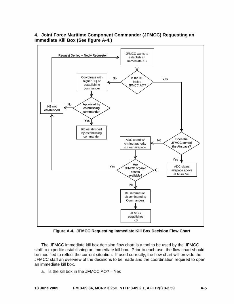
Element (GCE) Requesting Immediate Kill Box ......................... A-4Joint Force Maritime Component Commander (JFMCC)
Requesting an Immediate Kill Box ............................................. A-5
APPENDIX B COMPONENT COMMANDERS KILL BOX COORDINATION EXAMPLES ............................................... B-1Kill Box Execution: Examples of Cross-component Coordination ..... B-1JFLCC Planned Kill Box Example ..................................................... B-1JFLCC Immediate Kill Box Example.................................................. B-2JFMCC Planned Kill Box Example .................................................... B-3JFMCC Immediate Kill Box Example................................................. B-4JFACC Planned Kill Box Example ..................................................... B-5JFACC Immediate Kill Box Example ................................................. B-7JFSOCC Planned Kill Box Example .................................................. B-9JFSOCC Immediate Kill Box Example............................................. B-10ASOC-directed Employment of Scheduled or On-Call CAS
Missions in an Interdiction Role in a Kill Box............................ B-11
APPENDIX C EXAMPLE PROCEDURES FOR ESTABLISHING KILL BOXES ................................................................................... C-1JFLCC Procedures for Planned Kill Boxes ........................................C-1JFLCC Procedures for Immediate Kill Boxes ....................................C-2JFMCC Procedures for Planned Kill Boxes .......................................C-3JFMCC Operations for Immediate Kill Boxes ....................................C-4JFACC Operations for Planned Kill Boxes ........................................C-5JFACC Operations for Immediate Kill Boxes.....................................C-6JFSOCC Operations for Planned Kill Boxes......................................C-7JFSOCC Operations for Immediate Kill Boxes ..................................C-8
APPENDIX D THEATER-SPECIFIC KILL BOX PROCEDURES.................. D-1Background........................................................................................D-1Geographic Combatant Command Kill Box Procedures....................D-1
FM 3-09.34, MCRP 3.25H, NTTP 3-09.2.1, AFTTP(I) 3-2.59 13 June 2005 vi

APPENDIX E COMMON GEOGRAPHIC REFERENCE SYSTEM (CGRS) ....................................................................................E-1Overview............................................................................................ E-1CGRS Labeling and Identification...................................................... E-1CGRS Development .......................................................................... E-3CGRS Applications ............................................................................ E-3Modernized Integrated Database (MIDB) Integration ........................ E-4
REFERENCES ................................................................................References-1
GLOSSARY ....................................................................................Glossary-1
INDEX ..........................................................................................Index-1
FIGURES Figure I-1. Life Cycle of a Kill Box....................................................... I-3
Figure A-1. JFACC Requesting Immediate Kill Box Decision
Figure A-2. Army Maneuver Unit Requesting Immediate Kill
Figure A-3. MAGTF GCE Requesting Immediate Kill Box
Figure A-4. JFMCC Requesting Immediate Kill Box Decision
Figure B-1. JFLCC Establishes Planned and Immediate Kill
Figure B-2. JFMCC Activates Planned and Immediate Kill
Figure B-3. Planned and Immediate Kill Boxes Outside JFC-
Figure B-4. Planned and Immediate Kill Boxes in Support of
Figure B-5. ASOC-Directed Employment of CAS Assets in an
Figure C-1. Example of Component Commander Kill Boxes in
Figure I-2. Representative Kill Box Locations..................................... I-4Figure I-3. Notional Kill Box Graphic Portrayal ................................... I-6Figure II-1. Notional Blue Kill Box ..................................................... II-4Figure II-2. Notional Purple Kill Box................................................... II-5Figure III-1. Kill Box Request Format................................................ III-2Figure III-2. Command and Control Agency Briefing ........................ III-4Figure III-3. Kill Box Check-In Briefing............................................. III-5Figure III-4. Kill Box Coordinator to Fighter Brief/Check-In.............. III-6Figure III-5. Kill Box Attack Brief ...................................................... III-7
Flow Chart .................................................................................. A-1
Box Decision Flow Chart ............................................................ A-2
Decision Flow Chart ................................................................... A-4
Flow Chart .................................................................................. A-5
Boxes ......................................................................................... B-2
Boxes ......................................................................................... B-4
designated AOs in Support of JFACC Operations ..................... B-7
JFSOCC Operations ................................................................ B-10
Interdiction Role in a Kill Box.................................................... B-12
JFC AO.......................................................................................C-1Figure C-2. JFLCC Planned Kill Box Information Flow......................C-2
13 June 2005 FM 3-09.34, MCRP 3.25H, NTTP 3-09.2.1, AFTTP(I) 3-2.59 vii
Figure C-3. JFLCC Immediate Kill Box Information Flow ..................C-3Figure C-4. JFMCC Planned Kill Box Information Flow....................C-4Figure C-5. JFMCC Immediate Kill Box Information Flow .................C-5Figure C-6. JFACC Planned Kill Box Information Flow .....................C-6Figure C-7. JFACC Immediate Kill Box Information Flow..................C-7Figure C-8. JFSOCC C2 Structure for Kill Box Operations ..............C-8Figure E-1. Common Geographic Reference System Example ....... E-2Figure E-2. MIDB LAT/LONG Example ............................................ E-5
TABLES Table II-1. Kill Box Responsibilities.................................................... II-6
FM 3-09.34, MCRP 3.25H, NTTP 3-09.2.1, AFTTP(I) 3-2.59 13 June 2005 viii
EXECUTIVE SUMMARY
KILL BOX
Multi-Service Tactics, Techniques, and Procedures for Kill Box Employment
Overview This publication updates the definition of the kill box and establishes it as a fire support
coordinating measure (FSCM). Commanders and staffs must understand the elements and use of kill boxes in order to plan, develop, and employ them effectively in support of the joint force commander’s (JFC) requirements. This publication offers a detailed explanation of kill box employment and provides information to effectively organize, plan, and execute kill box procedures in a multinational and joint environment. This document:
• Incorporates lessons learned and best practices from Operations Enduring Freedom (OEF) and Iraqi Freedom (OIF) and recent exercises.
• Provides basic background information on kill boxes.
• Outlines factors impacting the planning of kill boxes.
• Describes procedures and factors impacting the execution of kill boxes.
• Provides examples and scenarios involving kill box establishment and operations to better illustrate the concepts and employment of kill boxes.
Kill Box Overview Chapter I defines the term kill box and briefly describes the purpose, employment of, and
overarching concepts concerning kill boxes. It provides a graphic portrayal of these concepts and defines unique kill box terms used in the document.
Kill Box Planning and Development Considerations Chapter II provides an overview of the various planning and coordinating considerations. It
also describes the process of establishing kill boxes and describes the characteristics of the two types of kill boxes: the blue kill box which permits air-to-surface fires and the purple kill box which permits integration of surface-to-surface indirect fires with air-to-surface fires.
Note: Some terms used in this publication are not in accordance with published joint doctrine. However, the described terms are consistent with the intent of existing joint doctrine.
13 June 2005 FM 3-09.34, MCRP 3.25H, NTTP 3-09.2.1, AFTTP(I) 3-2.59 ix

Kill Box Execution Procedures Chapter III describes factors and procedures (such as coordination) involved in conducting
kill box operations.
Appendices The appendices provide additional detailed information relevant to kill box procedures.
These include:
• Kill box request matrix.
• Component commanders kill box coordination examples.
• Example procedures for establishing kill boxes.
• Theater-specific kill box procedures.
• Common geographic reference system (CGRS).
FM 3-09.34, MCRP 3.25H, NTTP 3-09.2.1, AFTTP(I) 3-2.59 13 June 2005 x

PROGRAM PARTICIPANTS The following commands and agencies participated in the development of this publication:
Joint US Joint Forces Command, Norfolk, VA OSD Joint Test and Evaluation, Joint Test Support Cell, Suffolk, VA Joint Fires Coordination Measures Joint Feasibility Study, AWFC, Nellis AFB, NV
Army US Army Training and Doctrine Command, Futures Center, JADD, Fort Monroe, VA US Army Training and Doctrine Command, Combined Arms Center, CADD,
Fort Leavenworth, KS US Army Training and Doctrine Command, Combined Arms Center, AJST,
Hurlburt Field, FL US Army Field Artillery School, DOTD, Fort Sill, OK US Army Air Defense School, Fort Bliss, TX US Army Armor Center, Fort Knox, KY US Army Space and Missile Defense Command/ARSTRAT, Peterson AFB, CO US Army JFK Special Warfare Center and School, Fort Bragg, NC US Army Intelligence Center and Fort Huachuca, Fort Huachuca, AZ
Marine Corps Marine Corps Combat Development Command, Quantico, VA Marine Aviation Weapons and Tactics Squadron-1, Yuma, AZ II Marine Expeditionary Force/G-3, Camp Lejeune, NC Amphibious Group Two, San Diego, CA
Navy Navy Warfare Development Command (Norfolk Detachment), Norfolk, VA Naval Strike and Air Warfare Center, Fallon, NV Strike Fighter Weapons School, Atlantic, NAS Oceana, VA OPNAV N3/N5 DEEP BLUE, Washington DC Hawkeye Weapons and Tactics Unit Atlantic, Norfolk, VA
Air Force HQ Air Force Doctrine Center, Maxwell AFB, AL HQ USAF/JAO, Operations Law Division, Washington DC HQ Air Combat Command/DOYA, Langley AFB, VA HQ Air Combat Command/DOTW, Langley AFB, VA HQ Air Combat Command/DR-UAV SMO, Langley AFB, VA HQ Pacific Air Forces/DOTW, Hickam AFB, HI HQ Air Warfare Center/DO, Nellis AFB, NV Eighth Air Force/608th Air Operations Group, Barksdale AFB, LA Ninth Air Force/609th Combat Operations Squadron, Shaw AFB, SC
13 June 2005 FM 3-09.34, MCRP 3.25H, NTTP 3-09.2.1, AFTTP(I) 3-2.59 xi

98th Range Wing, Nellis AFB, NV 93rd Bomb Squadron, Barksdale AFB, LA 16th Operation Support Squadron/OSKW, Robins AFB, GA AFRL, Wright Patterson AFB, OH AFC2ISRC, Langley AFB, VA Air Ground Operations School, Nellis AFB, NV Detachment 2, 605th Test Squadron, Melbourne, FL 505th Command and Control Wing, Hurlburt Field, FL
FM 3-09.34, MCRP 3.25H, NTTP 3-09.2.1, AFTTP(I) 3-2.59 13 June 2005 xii
Chapter I
KILL BOX OVERVIEW
1. Definition and Purpose
a. Definition: A kill box is a three-dimensional fire support coordinating measure (FSCM) used to facilitate the expeditious air-to-surface lethal attack of targets, which may be augmented by or integrated with surface-to-surface indirect fires. While kill boxes are permissive FSCMs with respect to the deliverance of air-to-surface weapons they are also restrictive in nature; trajectories and effects of surface-to-surface indirect fires are not normally allowed to pass through the kill box. A kill box is a unique FSCM that may contain other measures within its boundaries [e.g., no-fire areas (NFAs), restricted operations area (ROAs), airspace coordination areas (ACAs), etc.]. Restrictive FSCMs and airspace control measures (ACMs) will always have priority when established in a kill box.
b. Purpose: When established, the primary purpose of a kill box is to allow air assets to conduct interdiction against surface targets without further coordination with the establishing commander and without terminal attack control. A kill box will not be established specifically for close air support (CAS) missions. However, this does not restrict CAS missions inside of established kill boxes if all CAS requirements are met. When used to integrate air-to-surface and surface-to-surface indirect fires, the kill box will have appropriate restrictions. The goal is to reduce the coordination required to fulfill support requirements with maximum flexibility, while preventing fratricide.
2. Establishment
A kill box is established and adjusted by component commanders in consultation with superior, subordinate, supporting, and affected commanders, and is an extension of an existing support relationship established by the joint force commander (JFC). Kill box boundaries normally are defined using an area reference system (e.g., Appendix E, Common Geographic Reference System [CGRS]), but could follow well defined terrain features or may be located by grid coordinates or by a radius from a center point. Changes in the status of established kill boxes, as with other FSCMs and/or airspace control measures (ACMs), must be coordinated as far in advance as possible. All joint force coordinating agencies must inform their forces of the effective times and locations of new FSCMs and/or ACMs. Following the direction to execute the change, the component operations cells should confirm the changes to ensure that affected forces are aware of new FSCM and/or ACM locations and that associated positive control measures are being followed. The two types of kill boxes and the terminology used during the life cycle of a kill box are defined below:
a. Blue Kill Box. A blue kill box permits air-to-surface fires in the kill box without further coordination with the establishing headquarters.
b. Purple Kill Box. Same as above, plus a purple kill box permits the integration of surface-to-surface indirect fires with air-to-surface fires into the purple kill box without further coordination with the establishing headquarters.
13 June 2005 FM 3-09.34, MCRP 3.25H, NTTP 3-09.2.1, AFTTP(I) 3-2.59 I-1

c. Life Cycle of Kill Box Terminology. (See figure I-1.)
(1) Established. Term used to describe a kill box that is in effect, either planned via the joint targeting cycle or immediate during execution. Information about the time it becomes established, the duration, and other attributes will be published and disseminated using existing voice and digital command and control (C2) systems (e.g., Automated Deep Operations Coordination System [ADOCS], Advanced Field Artillery Tactical Data System [AFATDS], theater battle management core system [TBMCS], or fragmentary order [FRAG order] from the establishing headquarters [HQ]).
(a) Open. Term used to describe a portion or portions of a kill box that are open to fires without further coordination or deconfliction. An established kill box is inherently open, until closed or cancelled.
• Active. An established kill box that has aircraft flying in the space defined by the box or effects of air or other joint fires within the boundaries of the kill box.
• Cold. An established kill box that is not active. All portions of the kill box are open to fires unless identified as closed.
(b) Closed. Term used to describe a portion or portions of an established kill box in which fires or effects of fires are not allowed without further coordination.
(2) Cancelled. The kill box is no longer in effect.
d. Area Reference System. Primarily an operational-level administrative measure used to coordinate geographic areas rapidly for battlespace deconfliction and synchronization. This reference system provides a common language between the components and simplifies communications (e.g., Appendix E, “Common Geographic Reference System;” and JP 3-60, Joint Doctrine for Targeting, Appendix D, “Common Reference Systems: Area and Point”).
Note: Combatant commanders will define the naming convention for the employment of kill boxes within their area of responsibility (AOR).
FM 3-09.34, MCRP 3.25H, NTTP 3-09.2.1, AFTTP(I) 3-2.59 13 June 2005 I-2

13 June 2005 FM 3-09.34, MCRP 3.25H, NTTP 3-09.2.1, AFTTP(I) 3-2.59 I-3
Figure I-1. Life Cycle of a Kill Box
3. Employment
Kill boxes are normally used when a support relationship already exists between two or more functional or Service components. The goal is to reduce the coordination required to fulfill support requirements with maximum flexibility, while preventing fratricide. (See figure I-2.)
a. Kill boxes support the commander’s objectives and concept of operations (CONOPS). As such, all target engagements within a kill box must adhere to the establishing commander’s designated target priorities, effects, and timing of fires.
b. Use of kill boxes is not mandatory.
c. C2 updates on kill boxes will be accomplished (e.g., altitude restrictions, frequency use, established control measures within the kill box) via appropriate C2 systems.
d. It is important to note that establishing a kill box is similar to establishing a target. This step only identifies an area where effects are desired. Additional action is required to identify and task assets to conduct attacks in this kill box. Those actions will be conducted within the standard joint and Service targeting cycles and in conjunction with the air tasking cycle.
Kill Box Cancelled
Life Cycle of a Kill Box
AB1
2 AB1
2
I need a kill box in cell 1B from 0200-1700Z
Key Pad 1B9 Closed1030-1100
Blue
Purple
Blue
Blue
1400Z
0200Z 0500Z
1100Z 1700Z
Planned orImmediate
Kill Box EstablishedReference System
Status: Cold Status: Active
Status: Cold Status: Active
AB1
2
9
Blue orPurple
Blue orPurple
Kill Box Cancelled
Life Cycle of a Kill Box
AB1
2 AB1
2A
B12
I need a kill box in cell 1B from 0200-1700Z
Key Pad 1B9 Closed1030-1100
Blue
Purple
Blue
Blue
1400Z
0200Z 0500Z
1100Z 1700Z
Planned orImmediate
Kill Box EstablishedReference System
Status: Cold Status: Active
Status: Cold Status: Active
AB1
2
9
Blue orPurple
Blue orPurple

I-4 FM 3-09.34, MCRP 3.25H, NTTP 3-09.2.1, AFTTP(I) 3-2.59 13 June 2005
e. Linear Battlespace. Kill boxes can augment use of traditional FSCMs, such as fire support coordination line (FSCL), coordinated fire line, and battlefield coordination line (BCL). They can help the commander focus the effort of air and indirect fire assets.
f. Non-linear Battlespace. When traditional FSCMs are not useful or are less applicable, the kill box can be another method for identifying areas to focus air and indirect fire assets.
g. Altitudes. The minimum and maximum altitudes may be disseminated in the special instructions (SPINS) or in the establishment order of the coordinating measure.
Figure I-2. Representative Kill Box Locations
4. Considerations
a. It is important to note that a kill box is an FSCM and is not a reference system. Kill box boundaries are normally defined using an area reference system which provides the construct (a two-dimensional system) while a kill box (a three-dimensional system) is the application.
b. Applicable rules of engagement (ROE), collateral damage (CD) guidance and restrictions, positive identification (PID), and the SPINS must still be followed in a kill box.
c. The decision to use a kill box requires careful consideration by the JFC or the establishing commander. If used, its size, location, and timing are based on estimates of the situation and CONOPS. Disposition of enemy forces, friendly forces, anticipated rates of movement, concept and tempo of the operation, surface-to-surface indirect weapon capabilities, and other factors must be considered by the commander.
d. There should be no friendly ground forces within or maneuvering into established kill boxes. If circumstances require otherwise (e.g., long-range reconnaissance patrols, special operations forces (SOF) teams, etc.), then NFAs must be established to cover those forces, or the kill box must be closed. The joint force commands must maintain awareness of
JFACC
JFSOCC
AOA
JFC
JFLCC
JFMCC
JFACC
JFSOCC
AOA
JFC
JFLCC
JFMCC

locations of friendly ground forces and the status of kill boxes within the AOR and maintain timely management of kill boxes to prevent fratricide.
e. A kill box may contain other measures within its boundaries [e.g., NFAs, ROAs, ACAs, etc.]. Restrictive FSCMs and ACMs will always have priority when established in a kill box.
f. Integration of air-to-surface fires and surface-to-surface indirect fires requires application of appropriate restrictions: altitude, time separation, or lateral separation. The establishing commander will determine which of these is appropriate for the mission and ensure dissemination through the appropriate C2 nodes.
g. Surface-to-surface direct fires, however, are not restricted by the establishment of a kill box.
h. All available aircraft will be tasked on the daily air tasking order (ATO) with either scheduled or on-call missions. Aircraft to be used to conduct interdiction missions in kill boxes should normally come from the same mission set, most likely the on-call interdiction missions without specific targets. Alternately, kill boxes may be used as target locations for preplanned requests for scheduled and on-call missions.
i. The first forward air controller (airborne) [FAC(A)], strike coordination and reconnaissance (SCAR), mission commander, or flight lead on station is responsible for deconfliction and coordination, if required.
5. Graphic Portrayal
The kill box is graphically portrayed by a solid black line defining the area with diagonal black lines within (figure I-3). The letters “BKB” (blue kill box) or “PKB” (purple kill box), followed by the establishing HQ, the effective date time group (DTG), and the effected altitudes (if different from the SPINS) are also within the defined area as required. Units and/or automation systems may add color to the boxes for visual recognition; however, the basic graphic should meet the standards of an FSCM. On-order kill boxes (not currently in effect) do not have to be displayed or may be represented by a box without diagonal lines.
13 June 2005 FM 3-09.34, MCRP 3.25H, NTTP 3-09.2.1, AFTTP(I) 3-2.59 I-5

BKBEst. HQ
DTGAltitude
BKBEst. HQ
DTG
PKBEst. HQ
DTG
BKBEst. HQ
DTG
BKBEst. HQ
DTG
PKBEst. HQ
DTGAltitude
BKBEst. HQ
DTG
PKBEst. HQ
DTG
44
33
5
1 2 3
4 6
87 9
5
1 2 3
4 6
87 9
BKB Est. HQ
DTG Altitude
BKB Est. HQ
DTG
PKB Est. HQ
DTG
BKB Est. HQ
DTG
BKB Est. HQ
DTG
PKB Est. HQ
DTG Altitude
BKB Est. HQ
DTG
PKB Est. HQ
DTG
JFLCCJFLCCBoundaryBoundary
FSCLFSCL
22
11
A B C D E F G H I JA B C D E F G H I JFigure I-3. Notional Kill Box Graphic Portrayal
Note: This diagram depicts the FSCL conforming to an area reference system for graphic portrayal only. Joint doctrine states the FSCL should follow well-defined terrain features.
FM 3-09.34, MCRP 3.25H, NTTP 3-09.2.1, AFTTP(I) 3-2.59 13 June 2005 I-6

Chapter II
KILL BOX PLANNING AND DEVELOPMENT CONSIDERATIONS
1. General
a. The JFC establishes detailed procedures and CONOPS for successful kill box employment within the joint operations area (JOA) by promulgating guidance and priorities. Additionally, the JFC normally delegates to component commanders the authority to establish and adjust kill boxes in consultation with superior, subordinate, supporting, and affected commanders. Component commanders may further delegate that authority. The establishing commander is responsible for coordinating with and notifying all affected forces.
Note: For the purposes of this publication and the procedures described, the establishing commander is a component commander (e.g., JFACC, JFLCC, JFMCC, or JFSOCC).
b. An area reference system facilitates the structural and procedural requirements for using kill boxes, but it is not an absolute requirement.
c. Kill box procedures will not be ideal for every situation. Considerations of mission, enemy, terrain and weather, troops and support available–time available (METT-T) (Army adds civil considerations) and requirements for terminal attack control may determine that other procedures would be more effective.
2. Planning Considerations
a. Kill boxes can be applied to different portions of the battlespace, including rear areas, to facilitate expeditious target engagement. Also, the kill box may be an applicable tool where traditional coordination measures (e.g., FSCL) do not exist or have not been established. Kill boxes can be used in conjunction with existing FSCMs.
b. The component commanders must be able to communicate kill box status in a timely manner. This will ensure systems and organization databases are updated. The architecture and means by which this information is disseminated should be identified early in the planning process. It must accommodate both planned and immediate kill boxes. Communications methods may include joint and multinational digital and voice systems. Units responsible for input of kill box status, as well as the primary and secondary systems which the information will be passed, must be identified to ensure timely dissemination of kill box status.
c. Establishing a kill box requires careful planning and coordination. Some of the considerations for successful planning are:
(1) Commander’s guidance and intent.
(2) Targeting priorities.
(3) Intelligence preparation of the battlespace.
(4) Location of other FSCMs and ACMs.
13 June 2005 FM 3-09.34, MCRP 3.25H, NTTP 3-09.2.1, AFTTP(I) 3-2.59 II-1

(5) CONOPS and scheme of maneuver (kill boxes should not impede or adversely impact the scheme of maneuver). Kill boxes are intended to facilitate rapid engagement of targets in conjunction with the commander’s concept of operation.
(6) Friendly locations and capabilities including SOF and other government agencies (OGAs).
(a) Restrictive fire support coordination measures (e.g., restricted fire area (RFA), NFA, or closed portion of kill box) take precedence over kill boxes, in order toprotect friendly forces on the ground.
(b) The burden of friendly deconfliction is the responsibility of the establishing headquarters. The establishing headquarters is also responsible for clearance of fires within the kill box.
(c) Consider the impact on the range and trajectory of surface-to-surface indirect fires.
(d) Surface-to-air fires responsiveness could be reduced due to additional coordination requirements.
(e) Weapons release may occur outside the confines of the kill box where effects are intended. Special considerations may be required for certain stand-off weapons, such as Tomahawk land attack missiles (TLAMs) or conventional air-launched cruise missiles (CALCMs), with respect to flight path deconfliction.
(7) Communication. Kill box frequencies must be considered in the development of the communications plan, and communication nets between C2 and fire assets must be clearly established. Ideally there will be a frequency associated with a specific kill box. This will enable the assets entering the kill box to have a common frequency for coordination. As the number of kill boxes established increases, the available number of frequencies decreases and reduces flexibility.
(8) ROE. Target engagement within an established kill box must still adhere to applicable elements of theater ROE (e.g., ROE for air integration). Planners at the joint and component level should determine if the current ROE are appropriate or unduly restricts target engagement within kill boxes and should request appropriate ROE adjustments, as required.
(9) Restrictions. Planners developing kill boxes must be aware that there are many constraints and restrictions that may impact how operations are executed within the kill box. Such restrictions could include requirements regarding CD, PID, restricted target list (RTL) or no-strike list (NSL). These restrictions will be published in the appropriate CONOPs and/or SPINS.
3. Kill Box Development
a. Kill boxes are tools for coordinating fires, but they are not the only tools. Commanders retain at their disposal their full range of FSCMs and ACMs to manage the battlespace.
(1) Planned. A planned kill box is developed during the planning process (i.e., joint targeting cycle, air tasking cycle, military decision making process, deliberate planning process). Planners must ensure dissemination of all planned FSCMs, ensuring kill boxes are in the airspace control order (ACO) or SPINS. Widest dissemination of the plan will enable greater understanding of the CONOPS. A kill box can be planned in a target area of
FM 3-09.34, MCRP 3.25H, NTTP 3-09.2.1, AFTTP(I) 3-2.59 13 June 2005 II-2

interest (TAI) where a commander might expect the requirement for a specified time period. TBMCS applications require that air assets be directed to a specific reference point or airspace. Kill boxes that are built in the modernized integrated database (MIDB) as facility targets can be processed by TBMCS as target locations. Specific instructions for planned kill boxes will be disseminated via the individual mission amplification (MSN AMPN) field in the ATO or in the SPINS. Procedures for each theater may vary.
(2) Immediate. An immediate kill box is developed and established during the execution phase of an operation. Immediate kill boxes are established by the current operations sections within each command and disseminated via appropriate means (voice and digital) to ensure visibility across the joint force. If the establishing commander needs to establish a kill box that cannot be promulgated through planning documents, he/she calls their liaison element such as a battlefield coordination detachment (BCD) or goes through the direct air support center (DASC)/air support operations center (ASOC) to inform the joint air operations center (JAOC) that a kill box was established and the time it will be open. C2 systems must be updated to reflect the new FSCM.
(3) On-Order. An on-order kill box is planned without a specific time for it to be established. The establishment may be triggered by an event(s). This kill box may have restrictions listed, but more likely, specific coordination for this kill box will occur with the notification to change its status to current.
Note: For detailed procedures for establishing kill boxes, see Appendix C.
b. While kill boxes are permissive FSCMs, with respect to the delivery of air-to-surface weapons, they are also restrictive in nature. Trajectories and effects of surface-to-surface indirect fires are not allowed to pass through a blue kill box. Also air-to-surface munitions (and their trajectories) delivered by aircraft not assigned to the kill box are not permitted to pass through an active kill box unless coordinated with the designated controlling authority. All aircraft not assigned to operate within a kill box are restricted from flying through an active kill box without permission of the designated controlling authority.
c. The primary purpose of permissive measures is to facilitate the attack of targets. Permissive measures require no further detailed coordination for the engagement of targets with conventional means. Restrictive measures (e.g., restrictive fire line, RFA, and NFA) impose requirements for specific coordination before engagement of targets. For example, aircraft cannot drop on an established NFA and must abide by the confines of an ACA. However, a kill box may take priority over permissive FSCMs. For example, a FSCL that crosses an established kill box does not automatically close that kill box.
d. Engagement authority is automatically granted by the establishment of a kill box but does not relieve the aircrew of the responsibility for complying with requirements such as commander’s designated target priority, PID, CD, ROE, and SPINS.
4. Blue Kill Box
a. Primary Purpose. The primary purpose of a blue kill box is to permit air-to-surface fires in the kill box without further coordination or deconfliction (figure II-1). If the kill box is active, air-to-surface munitions (and their trajectories) delivered by aircraft not assigned to the blue kill box need to be coordinated. All aircraft not assigned to an active blue kill box are restricted from flying through it unless coordinated with the kill box coordinator (KBC). The airspace included by a blue kill box extends from the surface up to the limit established by the airspace control authority.
13 June 2005 FM 3-09.34, MCRP 3.25H, NTTP 3-09.2.1, AFTTP(I) 3-2.59 II-3

II-4 FM 3-09.34, MCRP 3.25H, NTTP 3-09.2.1, AFTTP(I) 3-2.59 13 June 2005
Note: Ordnance may be delivered from outside the airspace defined by the kill box to include stand-off surface-to-surface indirect and air-to-surface weapons (figures II-1 and II-2).
b. Permits Rapid Engagement. A blue kill box minimizes the restrictions on air-to-surface fires, while also protecting aircraft. Effects and trajectories of surface-to-surface indirect fires are not allowed to pass through the blue kill box. Land and maritime force commanders must coordinate with the air component to deliver surface-to-surface indirect fires into or through an established blue kill box. The primary purpose of permissive measures is to facilitate the attack of targets. Permissive measures require no further detailed coordination for the engagement of targets with conventional means. Restrictive measures impose requirements for specific coordination before engagement of targets.
Figure II-1. Notional Blue Kill Box
5. Purple Kill Box
a. Primary Purpose. The primary purpose of a purple kill box is to reduce the coordination requirements for air-to-surface fires, while still allowing surface component commanders to employ surface-to-surface indirect fires. The purple kill box allows the maximum use of joint fires in the kill box creating a synergistic effect and maximum potential for engaging targets.
b. Permits Integration of Fires. A purple kill box permits the integration of surface-to-surface indirect fires with air-to-surface fires into the purple kill box without further coordination (figure II-2). Air-to-surface and surface-to-surface indirect fires can be deconflicted by altitude, lateral, or time separation. The establishing headquarters will
Kill Box Ceiling
LegendTargetExamples of Restrictive Measures:
No-Fire Area (NFA)No-Strike
Blue Kill Box
Kill BoxPermitted
• A/C• A-S Internal Trajectories
Kill Box Ceiling
LegendTargetExamples of Restrictive Measures:
No-Fire Area (NFA)No-Strike
Blue Kill Box
Kill BoxPermitted
• A/C• A-S Internal Trajectories

13 June 2005 FM 3-09.34, MCRP 3.25H, NTTP 3-09.2.1, AFTTP(I) 3-2.59 II-5
coordinate with the air component to define the appropriate deconfliction technique for operations within the purple kill box. All aircraft not assigned to an active purple kill box are restricted from flying through it unless coordinated. Also air-to-surface munitions (and their trajectories) delivered by aircraft not assigned to the kill box will not violate the purple kill box unless coordinated. Ground units subordinate to the establishing commander are required to obtain clearance from the air component for any surface-to-surface indirect fires when their trajectories will violate the altitude, lateral, or time restrictions. Ground units from other components must coordinate fires with the establishing commander as well.
c. Deconfliction Techniques (1) Lateral Separation. Lateral separation is effective for coordinating fires against
targets that are adequately separated from flight routes to ensure aircraft protection from the effects of friendly fires.
(2) Altitude Separation. Altitude separation is effective for coordinating fires when aircrews will remain above or below indirect fire trajectories and their effects.
(3) Altitude and Lateral Separation. Altitude and lateral separation is the most restrictive technique for aircrews and may be required when aircraft must cross the firing unit’s gun-target line.
(4) Time Separation. Time separation requires the most detailed coordination and may be required when altitude restrictions from indirect fire trajectories (e.g., Army Tactical Missile System [ATACMS] trajectory) adversely impact aircraft ordnance delivery.
Figure II-2. Notional Purple Kill Box
26V
LegendTargetExamples of Restrictive Measures:
No-Fire Area (NFA)No-Strike
Purple Kill BoxKill Box Ceiling
Minimum Altitude
Kill BoxPermitted
• A/C• A-S Internal Trajectories
Kill BoxPermitted
• A-S Trajectories• S-S Trajectories
26V
LegendTargetExamples of Restrictive Measures:
No-Fire Area (NFA)No-Strike
Purple Kill BoxKill Box Ceiling
Minimum Altitude
Kill BoxPermitted
• A/C• A-S Internal Trajectories
Kill BoxPermitted
• A-S Trajectories• S-S Trajectories

3
6. Kill Box Responsibilities Matrix
The following matrix (table II-1) describes the responsibilities inherent in employment of the types of kill boxes.
Table II-1. Kill Box Responsibilities
Kill Box Responsibilities Matrix
Types/Location Establishing Commander1 Component Coordination Requirements
Blue or Purple Kill Box • Outside JFC-designated AOs
JFC
JFACC (when delegated)2
JFACC: No additional coordination required once established.
Other components: Must coordinate with JFACC.
Purple Kill Box Restrictions: Altitude, lateral, or time separation as specified when established.
Blue or Purple Kill Box • Inside JFC-designated AOs
Land, Maritime, or Service component commander3
JFACC: No additional coordination required once established, except changes in establishing commander target priorities, effects, and timing.
Establishing Headquarters: Must notify the JFACC when opening, closing, canceling, or changing the type of kill box or changes to establishing commander’s target priorities, effects, and timing.
Other components: Must coordinate with establishing headquarters.
Purple Kill Box Restrictions: Altitude, lateral, or time separation as specified when established.
1 The JFC may be the establishing commander for any FSCM within the AOR. 2 The JFC will normally delegate to the JFACC the authority for establishing kill boxes in unassigned areas of the JOA. The JFSOCC is the establishing commander for kill boxes inside a joint special operations area (JSOA).
FM 3-09.34, MCRP 3.25H, NTTP 3-09.2.1, AFTTP(I) 3-2.59 13 June 2005 II-6

Chapter III
KILL BOX EXECUTION PROCEDURES
1. Execution of Operations Within Kill Boxes
Kill box execution begins with the establishment of a kill box by a component commander and is dependant on two factors: the method by which a kill box is established (either planned or immediate) and types of fires to be delivered (either integrated surface-to-surface indirect and air-to-surface fires [purple kill boxes] or pure air-to-surface fires [blue kill boxes]).
2. Establishment and Cancellation of a Kill Box
a. Kill box establishment and adjustment requires the establishing commander to conduct detailed coordination and dissemination of information with superior, subordinate, supporting, and affected commanders within the JOA. The establishment of planned or immediate kill boxes will use existing theater command, control, communications, and computer systems. During execution, communications nets between C2 and air assets providing air-to-surface fires will be clearly established and used to terminate operations in a timely manner if necessary.
b. Component commanders initiate the establishment of a kill box through their operational C2 organization. (The recommended request format is provided in figure III-1.) They will coordinate their action with the airspace control authority, who is typically, but not always, the joint force air component commander (JFACC). Coordination will include consultation with the JFACC’s representatives on the impacts and details of the kill box. Example: The joint force land component commander (JFLCC) wants to establish a kill box in his/her operational area. Prior to establishing the kill box, the JFLCC will coordinate the impacts and details of the kill box with ASOC/JAOC via the fire support element (FSE).
Note: For detailed procedures for establishing kill boxes, see Appendix C.
13 June 2005 FM 3-09.34, MCRP 3.25H, NTTP 3-09.2.1, AFTTP(I) 3-2.59 III-1

KILL BOX REQUEST FORMAT
Purpose: ____________________________________________________________
Geographic limits/kill box location: ____________________________________
Effective times of establishment: ______________________________________
• Identify the date-time group (DTG) the kill box is established.
• Identify the DTG or the event that will cancel the kill box.
Kill Box Type: _______________________________________________________ (Identify whether it is blue or purple)
Establishing Commander: ____________________________________________ (Identify the establishing commander)
Establishing Commander’s Targeting Guidance: ________________________
• Priorities: List the targets.
• Effects: Identify the desired effects.
• Identify restrictions.
Remarks: ___________________________________________________________ (Give any additional information [e.g. NFA, no strike, etc.]
needed.)
Figure III-1. Kill Box Request Format
3. Contingencies and Considerations
a. The kill box is designed to rapidly provide a solution to the requirement for coordination of lethal fires. However, nonlethal fires such as electronic attack may be employed to facilitate fires and provide synergy of prosecution of a given target across the entire operational spectrum. Every attempt should be made to bring to bear all capabilities against a given target set to ensure its efficient destruction.
b. Additionally, established kill boxes in the vicinity of joint air defense assets can adversely affect the capabilities of the air defense system to operate as intended by the area air defense commander (AADC). Advise the AADC when a kill box is established in the vicinity of a joint air defense area.
FM 3-09.34, MCRP 3.25H, NTTP 3-09.2.1, AFTTP(I) 3-2.59 13 June 2005 III-2

4. Coordinating Operations Within Active Kill Boxes
Kill box coordination is required when multiple flights or formations are operating within or providing air-to-surface fires within the same kill box. This coordination may be as simple as deconflicting two flights or as complex as performing SCAR. At a minimum, this coordination must deconflict flight paths and weapons deliveries.
a. The functions associated with kill box coordination should not be confused with those of the FAC(A). FAC(A)s are a direct extension of a tactical air control party (TACP) or joint terminal attack controllers (JTAC) and specifically facilitate the conduct of CAS. Flights providing kill box coordination will not normally provide terminal attack control within a kill box. However, rapidly changing circumstances could require FAC(A)s to provide terminal attack control for CAS missions. In this case, the kill box or portions thereof will be closed and CAS procedures will be used.
b. Unless previously coordinated, the first flight to enter a given kill box will be responsible for providing the required kill box coordination. As the complexity of the kill box environment begins to exceed airframe capability or the flight’s training or comfort level, that flight should seek to pass the responsibility for providing kill box coordination to a more qualified flight. FAC(A)s or SCAR-trained flights are ideally suited and prepared to provide all of the capabilities described above. If no FAC(A), SCAR, or mission commander is available, the most qualified flight lead will conduct kill box coordination and will only be responsible for kill box deconfliction.
c. Once positive deconfliction has been established, kill box coordination may include any or all of the following:
(1) Expeditiously flowing interdiction aircraft into and out of the target area.
(2) Attempting to match weapons with targets and targeting priorities.
(3) Preventing redundant strikes against targets previously destroyed.
(4) Providing targeting information, to include accurate coordinates and PID.
(5) Providing target marks.
(6) Supporting laser-guided weapons.
(7) Confirming or locating surface-to-air threats.
(8) Providing battle damage assessment/bomb hit assessment (BHA).
5. Command and Control (C2) and Radio Procedures
Flights will check in with C2 agencies in accordance with (IAW) theater SPINS. Once authorized to proceed to a kill box, flights must check in with the agency or flight providing kill box coordination prior to entering that kill box. Recommended check-in and briefing formats are provided below. The applicable information from each format should be passed. At a minimum, the C2 agency will pass kill box location, status, coordinator, frequency, friendlies, and threats.
a. C2 Agency Check-in Standard IAW Theater SPINS. As time and conditions permit, amplifying information may be passed including some or all of the information in figure III-2.
13 June 2005 FM 3-09.34, MCRP 3.25H, NTTP 3-09.2.1, AFTTP(I) 3-2.59 III-3

COMMAND AND CONTROL AGENCY BRIEFING Information passed from C2 Agency to Aircraft
Aircraft Check-In: “C2 agency call sign, this is aircraft call sign”
C2 Response: “aircraft call sign, this is C2 agency call sign”
Targets: “__________________________________________________________” (priorities, targets being worked, etc.)
Threats: “__________________________________________________________”
Friendlies: “_______________________________________________________” (all applicable air and ground assets in vicinity of kill box)
Fires Integration: “_________________________________________________”
Coordinator: “______________________________________________________” (call sign and net)
Ordnance Restrictions or Requests: “_________________________________”
Remarks: “_________________________________________________________” (restricted targets or munitions, etc.)
Example:
“Kmart 00, this is Razor 22 checking in as fragged.”
“Razor 22, this is Kmart 00, proceed to 7F, target priorities are tanks and artillery, possible SA-8 in keypad 5, multiple aircraft on station, contact Badger 11 on TAD-2, no scatterable munitions.”
Figure III-2. Command and Control Agency Briefing
FM 3-09.34, MCRP 3.25H, NTTP 3-09.2.1, AFTTP(I) 3-2.59 13 June 2005 III-4

b. Kill Box Check-in Briefing (See figure III-3.)
KILL BOX CHECK-IN BRIEFING Passed to Kill Box Coordinator Before Entering
Aircraft: “KBC call sign, this is aircraft call sign”
Mission Number: “_________________________________________________”
Number and Type of Aircraft: “______________________________________”
Position and Altitude: “_____________________________________________”
Ordnance: “________________________________________________________” (laser codes as applicable)
Time on Station: “__________________________________________________”
Additional Aircraft/Aircrew Capabilities: “____________________________”
Remarks: “_________________________________________________________”
Example:
“Badger 11, this is Razor 22, mission #3601, flight of 2 x AV-8s, 50 nm south angels 26, 3 GBU-12s and Litening, 20 minutes playtime.”
Figure III-3. Kill Box Check-in Briefing
13 June 2005 FM 3-09.34, MCRP 3.25H, NTTP 3-09.2.1, AFTTP(I) 3-2.59 III-5

c. KBC to Fighter Brief/Check-in (See figure III-4.)
KBC TO FIGHTER BRIEF/CHECK-IN Passed from KBC
Aircraft: “aircraft call sign, this is KBC call sign”
Deconfliction Plan: “_________________________________________________”
Friendlies: “_________________________________________________________” (all applicable air and ground assets in kill box)
Targets: “___________________________________________________________” (priorities, targets being worked, etc)
Threats: “___________________________________________________________”
Kill Box Status and Restrictions: “____________________________________”
Remarks: “__________________________________________________________” (restricted targets or munitions, etc)
Example:
“Razor 22, this is Badger 11, descend to angels 20, proceed to 7F keypad 9, target priorities are tanks and artillery, possible SA-8 in 7F5, 7F is active blue kill box, be advised Ripper 33, established angels 18, 7F keypads 1, 2, and 3, Badger 11 angels 25, advise when ready to copy attack brief.”
Figure III-4. Kill Box Coordinator to Fighter Brief/Check-in
FM 3-09.34, MCRP 3.25H, NTTP 3-09.2.1, AFTTP(I) 3-2.59 13 June 2005 III-6

d. Kill Box Attack Brief (See figure III-5.)
KILL BOX ATTACK BRIEF KBC to Striker Aircraft
Aircraft: “KBC call sign, this is strike aircraft call sign”
Target Description: “_______________________________________________”
Target Location: “__________________________________________________” (coordinates, geographic references, etc.)
Target Elevation: “_________________________________________________”
Remarks: “_________________________________________________________” (buddy-lase plan, mark, time on target (TOT), deconfliction, etc.)
NOTE: Once established in the open kill box with flight and weapon deconfliction assured, authorization to engage targets is assumed once the following measures have been satisfied by the flight:
• PID
• FSCMs Restrictions
• Collateral Damage Estimations (CDEs)
• No-strike Lists/Restricted Target List
• ROE/SPINS
Example:
“Razor 22 Ready to copy.”
“Column of 4 APCs oriented north to south with dismounted infantry, location N3701.034 / W07601.089, elevation 69’, remain in 7F keypad 9, contact Badger 11 once complete.”
Figure III-5. Kill Box Attack Brief
e. Departing KBCs will execute a positive handoff to the appropriate flight, if applicable, and notify C2. If no flights are available, the KBC will execute a positive handoff with C2.
13 June 2005 FM 3-09.34, MCRP 3.25H, NTTP 3-09.2.1, AFTTP(I) 3-2.59 III-7

This page intentionally left blank.

JFACC request KB
Outside LCC Boundary
Coordinate w/ BCD/MARLO(or LCC directly) on KB
establishment requirements.
JAOC Current Ops
Airspace Cell checksACM conflicts /
determines ACM buildrequirement
BCD/A2C2 coordinates
w/ JAOC
Conflicts withATO, Fires
Coordinate KBEstablishmentMaintain status
Acceptablerisk
Notify requesterof conflict
Info fires elements at component and
JFC
EstablishingCommanderOpens KB
KB not established
Kill Box info posted / disseminated to all
components for visibility
Outside LCC Boundary
Coordinate w/ BCD/MARLO(or LCC directly) on KB
establishment requirements.
BCD/A2C2 coordinates
w/ JAOC
Conflicts withATO, Fires
KB not established
Appendix A
KILL BOX REQUEST MATRIX
1. Joint Force Air Component Commander (JFACC) Requesting Immediate Kill Box (See figure A-1.)
Yes No
JFLCC Approval
Yes
Yes
No
No
Yes
No
JFACC request KB
Outside LCC Boundary
Yes No
Coordinate w/ BCD/MARLO (or LCC directly) on KB
establishment requirements.
JFLCCApproval
JAOC Current Ops
Airspace Cell checks ACM conflicts /
determines ACM build requirement
BCD/A2C2 coordinates
w/ JAOC
Conflicts with ATO, Fires
Coordinate KB Establishment Maintain status
Acceptable risk
Yes
Yes
No
Notify requester of conflict
Info fires elements at component and
JFC
No
Establishing Commander Opens KB
Yes
KB not established
No
Kill Box info posted / disseminated to all
components for visibility
Figure A-1. JFACC Requesting Immediate Kill Box Decision Flow Chart
13 June 2005 FM 3-09.34, MCRP 3.25H, NTTP 3-09.2.1, AFTTP(I) 3-2.59 A-1

Appropriate GroundCmdr request KB
establishment(FSE, S-3, G-3, J-3)
Inside AOCoordinate
with higher oraffected
commander
JFLCC J-3 Approves
JFLCC FSE establishes KB
KB info disseminated toJFLCC & C2 agencies
[BCD, JAOC, JFC]
Approved byestablishingcommander
KB established byestablishing commander
KB not established by affected commander
KB info disseminated toJFLCC & C2 agencies
[BCD, JAOC, JFC]
Kill Box info posted / disseminated to all
components for visibility
Establish Additional FSCMs
Affected G-3/S-3/J-3 confirms KB is clear
of friendly troops
Affected G-3/S-3/J-3 confirms KB is clear
of friendly troops
2. Army Maneuver Unit Requesting Immediate Kill Box (See figure A-2.)
Yes
Yes
No
No
Request Denied – Notify Requestor
Yes
No
Yes
No
Appropriate Ground Cmdr request KB
establishment (FSE, S-3, G-3, J-3)
Inside AO Coordinate
with higher or affected
commander
JFLCC J-3 Approves JFLCC J-3 Approves
JFLCC FSE establishes KB
KB info disseminated to JFLCC & C2 agencies
[BCD, JAOC, JFC]
Approved by establishing commander
KB established by establishing commander
Yes
Yes
No
No
Request Denied – Notify Requestor
KB not established by affected commander
Yes
No
KB info disseminated to JFLCC & C2 agencies
[BCD, JAOC, JFC]
Kill Box info posted / disseminated to all
components for visibility
Yes
Establish Additional FSCMs
NoAffected G-3/S-3/J-3 confirms KB is clear
of friendly troops
Figure A-2. Army Maneuver Unit Requesting Immediate Kill Box Decision Flow Chart
The Army maneuver unit requesting an immediate kill box decision flow chart is a tool to be used by the staff to expedite the establishment of an immediate kill box. Prior to being used, the flow chart should be adjusted to reflect the current situation. If used correctly, the flow chart will provide the staff an overview of the decisions to be made and the coordination required to open an immediate kill box.
a. The fire support coordinator (FSCOORD) in consultation with the G-3/S-3/J-3 and air liaison officer (ALO) recommend that a kill box be established.
FM 3-09.34, MCRP 3.25H, NTTP 3-09.2.1, AFTTP(I) 3-2.59 13 June 2005 A-2

b. Is the kill box in the unit’s area of operation (AO) – Yes?
(1) Can G-3/S-3/J-3 confirm that there are no friendlies within the area of the kill box?
(a) If yes, the kill box recommendation goes forward.
(b) If no, the G-3/S-3/J-3 and the FSCOORD must make recommendations for additional FSCMs to protect those troops.
(2) Notify the air defense artillery (ADA) liaison officer (LNO) to establish a kill box. Coordinate on the LNO’s risk assessment, if submitted.
(3) Can the ALO/TACP ensure that the kill box establishment will not adversely affect air operations in support of the maneuver force or JFLCC operations?
(a) If yes, the kill box recommendation goes forward.
(b) If no, the ALO LNO must provide a risk assessment to the commander along with his/her recommendations.
(4) Weighing all the information and recommendations, the maneuver commander makes his/her decision on establishing the kill box.
(a) If yes, the kill box is established.
(b) If no, the kill box is not established.
c. Is the kill box in the unit’s AO – No?
(1) The FSE coordinates with the commander of the AO where the kill box is to be located and recommends that a kill box be established and provides all the information concerning the establishment of the kill box.
(2) The staff of the affected commander performs steps in b(1), (2) and (3).
d. Does the affected component commander approve the establishment of a kill box in his/her AO?
(1) If yes, the kill box information is established.
(2) If no, the kill box is not established.
e. Can the JFLCC clear the kill box for all friendly forces, e.g., special operations forces (SOF), other government agency (OGA), etc?
(1) If yes, the kill box information is disseminated to all component commanders prior to establishment.
(2) If no, the JFLCC deep operations coordination cell (DOCC)/FSE must establish additional FSCMs to protect those forces.
13 June 2005 FM 3-09.34, MCRP 3.25H, NTTP 3-09.2.1, AFTTP(I) 3-2.59 A-3

Ground CombatElement request KB
establishment (FSC, S-3, G-3)
InsideMAGTF AO
Coordinatewith higher or
AffectedCommander
Approved by affected
commander
KB established byAffected commander
KB info disseminated toJFLCC & C2 agencies
Forward to theMAGTF CE
FSCC
KB info disseminated toJFACC via MARLO
InsideMAGTF AO
Coordinatewith higher or
AffectedCommander
3. Marine Air-Ground Task Force (MAGTF) Ground Combat Element (GCE) Requesting Immediate Kill Box (See figure A-3.)
Yes
Yes
No
No
Request Denied – Notify Requestor
MAGTF CE FSCC
Establishes KB
TACC tasks assets to
the KB
Ground Combat Element request KB
establishment (FSC, S-3, G-3)
Inside MAGTF AO
Coordinate with higher or
Affected Commander
Approved by affected
commander
KB established by Affected commander
Yes
Yes
No
No
Request Denied – Notify Requestor
KB info disseminated to JFLCC & C2 agencies
Forward to the MAGTF CE
FSCC
MAGTF CEFSCC
Establishes KB
KB info disseminated to JFACC via MARLO
TACC tasks assets to
the KB
TACC tasks assets to
the KB
TACC tasks assets to
the KB
Figure A-3. MAGTF GCE Requesting Immediate Kill Box Decision Flow Chart
FM 3-09.34, MCRP 3.25H, NTTP 3-09.2.1, AFTTP(I) 3-2.59 13 June 2005 A-4
JFMCC wants toestablish an
Immediate KB
Is the KB inside
JFMCC AO?
AreJFMCC organic
assetsavailable?
Does theJFMCC controlthe Airspace?
ADC coord w/ cntrlng authorityto clear airspace.
Approved by establishing commander
KB informationdisseminated toCommanders
ADC clearsairspace above
JFMCC AO.
Coordinate withhigher HQ or establishing commander
JFMCCestablishes
KB
KB established by establishing
commanderDoes the
JFMCC controlthe Airspace?
Approved by establishing commander
4. Joint Force Maritime Component Commander (JFMCC) Requesting an Immediate Kill Box (See figure A-4.)
YesNo
No
Yes
No
Yes
KB not established
No
Request Denied – Notify Requester
Yes
JFMCC wants to establish an
Immediate KB
Is the KB inside
JFMCC AO?
Are JFMCC organic
assets available?
AreJFMCC organic
assetsavailable?
YesNo
Does the JFMCC control the Airspace?
Does theJFMCC controlthe Airspace?
ADC coord w/ cntrlng authority to clear airspace.
No
Yes
No
Yes
Approved by establishing commander
Approved by establishing commander
KB notestablished
No
Request Denied – Notify Requester
KB information disseminated to Commanders
ADC clears airspace above
JFMCC AO.
Coordinate with higher HQ or establishing commander
Yes
JFMCC establishes
KB
KB established by establishing
commander
Figure A-4. JFMCC Requesting Immediate Kill Box Decision Flow Chart
The JFMCC immediate kill box decision flow chart is a tool to be used by the JFMCC staff to expedite establishing an immediate kill box. Prior to each use, the flow chart should be modified to reflect the current situation. If used correctly, the flow chart will provide the JFMCC staff an overview of the decisions to be made and the coordination required to open an immediate kill box.
a. Is the kill box in the JFMCC AO? – Yes
13 June 2005 FM 3-09.34, MCRP 3.25H, NTTP 3-09.2.1, AFTTP(I) 3-2.59 A-5

b. The JFMCC control the airspace defined by the kill box?
(1) If yes, the air defense commander (ADC) clears the airspace defined by the kill box.
(2) If no, the ADC coordinates with the airspace control authority (normally delegated to the Chief of Combat Operations [CCO] working for the JFACC in the JAOC) to clear the airspace defined by the kill box.
(3) Are JFMCC organic assets available?
(a) If yes, a kill box is not established. (b) If no, the kill box information (KB type, location, establishing
headquarters, and time established, etc.) is disseminated to all component commanders prior to establishment.
c. Is the kill box in the JFMCC AO? – No
(1) JFMCC current operations coordinates with the establishing headquarters to establish a kill box.
(2) Does the establishing headquarters approve the establishment of a kill box in his/her AO?
(a) If yes, the kill box information (KB type, location, establishing headquarters, and time established, etc.) is disseminated to all component commanders prior to establishment.
(b) If no, a kill box is not established.
FM 3-09.34, MCRP 3.25H, NTTP 3-09.2.1, AFTTP(I) 3-2.59 13 June 2005 A-6

Appendix B
COMPONENT COMMANDERS KILL BOX COORDINATION EXAMPLES
1. Kill Box Execution: Examples of Cross-component Coordination
The following mission examples demonstrate how the kill box process can be implemented across components. The examples explore different possibilities and illustrate key concepts in coordination of kill boxes, but are not intended to be all-inclusive.
2. JFLCC Planned Kill Box Example
a. The JFLCC staff during the military decision-making process has identified an area of expected enemy concentrations of armored forces in areas well beyond the forward line of own troops (FLOT) and beyond the expected movement of friendly forces for the next 48 hours. Intending to shape the battlespace, the FSCOORD and ALO recommend that the JFLCC establish a kill box over the area. This will allow air assets to attack enemy targets without further coordination. The kill box will not adversely affect ADA coverage for the land component. (See figure B-1, blue kill box.) They submit the following kill box request:
(1) Purpose: To destroy enemy armor assets in the area and degrade enemy forces for the friendly forces.
(2) Geographic limits/kill box location: Using the area reference system, the entire cell 24K is identified as a kill box.
(3) Effective times of establishment:
(a) Established at 240600ZAug04
(b) Cancelled 260600ZAug04 or on-order
(4) Kill Box Type: BLUE
(5) Establishing Commander: JFLCC
(6) Establishing Commander’s Targeting Guidance:
(a) Priorities: Tanks, ADA, and armored vehicles.
(b) Effects: Destroy/neutralize when found.
(c) Restrictions: Do not destroy bridges or road networks. No scatterable munitions near bridges, roads, or road intersections.
(7) Remarks: No friendlies are within the proposed kill box. NFAs have been established around restricted and no-strike targets.
13 June 2005 FM 3-09.34, MCRP 3.25H, NTTP 3-09.2.1, AFTTP(I) 3-2.59 B-1

B-2 FM 3-09.34, MCRP 3.25H, NTTP 3-09.2.1, AFTTP(I) 3-2.59 13 June 2005
Figure B-1. JFLCC Establishes Planned and Immediate Kill Boxes
3. JFLCC Immediate Kill Box Example
a. During shore operations, the HQ of the Marine air-ground task force (MAGTF) receives intelligence reports concerning stationary and advancing enemy forces within their AO. The enemy armored and mechanized units are short of the FSCL but beyond the BCL and the range of Marine organic indirect fires. The FSCOORD and air officer recommend that a purple kill box be established immediately to bring maximum joint fires to bear on the target. The JFLCC (Marine expeditionary force [MEF] commander) agrees and establishes the kill box. (See figure B-1, purple kill box.)
b. A message is prepared with the following information:
(1) Purpose: To destroy enemy armor and mechanized forces before they reach Marine Corps units.
(2) Geographic limits/kill box location: Using the area reference system, the quadrant 26G5SE is identified as a kill box.
(3) Effective Times: (a) Established: Immediately
AOA
JFACC:JAOC/BCD
JFLCC:DOCC/FSE
24K 26G5SW
24K(Blue)
LegendTargetsExamples of Restrictive Measures:
No-Fire Area (NFA)No-Strike
26G5SW(Purple)
AOA
JFACC:JAOC/BCD
JFLCC:DOCC/FSE
24K 26G5SW
24K(Blue)
LegendTargetsExamples of Restrictive Measures:
No-Fire Area (NFA)No-Strike
26G5SW(Purple)

(b) Cancelled: On-order
(4) Kill Box Type: PURPLE, minimum altitude 12,000 ft mean sea level (MSL) maximum altitude 25,000 ft MSL.
(5) Establishing Commander: JFLCC
(6) Establishing Commander’s Targeting Guidance:
(a) Priorities: Tanks, armored vehicles, artillery.
(b) Effects: Destroy. Do not destroy bridges or road networks.
(7) Remarks: No friendlies are within the proposed kill box. There are no restricted or no strike targets within the kill box.
4. JFMCC Planned Kill Box Example
a. A Marine expeditionary brigade (MEB) level amphibious assault is scheduled to take place in 5 days within an amphibious objective area (AOA) designated by the JFC. The intelligence section of the command element briefs the ground combat element (GCE) commander (regimental combat team [RCT] commanding officer [CO]) on an enemy high speed armor avenue of approach into the AOA. The RCT CO determines the need to shape the amphibious landing area in preparation for the amphibious assault. His/her FSCOORD and air officer recommend establishing a purple kill box over the area. This will allow for air assets and naval surface fire support (NSFS) to engage targets in the area without further coordination. (See figure B-2, purple kill box.)
b. The RCT CO purple kill box request is based on the following information:
(1) Purpose: To destroy enemy armor assets in the area and prohibit enemy forces from approaching the beachhead area.
(2) Geographic limits/kill box location: Using the area reference system, the entire keypad 29W is identified as a kill box.
(3) Effective Times:
(a) Established at 0600Z D-3
(b) Cancelled at 0600Z D-day
(4) Kill Box Type: PURPLE
(5) Establishing Commander: JFMCC
(6) Establishing Commander’s Targeting Guidance:
(a) Priorities: Tanks, armored vehicles, artillery.
(b) Effects: Destroy. Do not destroy bridges or road networks. No scatterable munitions near bridges, roads, or road intersections.
(7) Remarks: No friendlies are within the proposed kill box. NFAs have been established around restricted and no-strike targets.
13 June 2005 FM 3-09.34, MCRP 3.25H, NTTP 3-09.2.1, AFTTP(I) 3-2.59 B-3

B-4 FM 3-09.34, MCRP 3.25H, NTTP 3-09.2.1, AFTTP(I) 3-2.59 13 June 2005
Figure B-2. JFMCC Activates Planned and Immediate Kill Boxes
5. JFMCC Immediate Kill Box Example
a. A P-3 on a maritime patrol mission identifies an enemy ship (a submarine) being loaded with mines in a port facility. The P-3 reports its findings to the strike warfare commander (SWC) watch, in the Combat Division Center. The SWC watch simultaneously relays the information to JFMCC current operations in the Maritime Operating Center (MOC) and looks for a surface asset to intercept the submarine prior to getting underway. JFMCC Current Operations tasks the SWC watch (Bravo Papa) to locate a direct-use aircraft for tasking. JFMCC Current Operations receives the following information from Bravo Papa and the SWC watch: No aircraft are available for a potential strike and the closest naval combatant ship has a 5-hour transit time to intercept the submarine. (See figure B-2.)
b. In addition to no-strike aircraft or surface combatants to engage the submarine, there are no preplanned Tomahawk missions for the port facility. JFMCC Current Operations determines that the most expeditious method of destroying the enemy submarine prior to getting underway is to establish and activate a blue kill box over the submarine for JFACC air assets to engage. JFMCC Current Operations coordinates with the JFACC JAOC through the Navy liaisons and passes the following information to establish the blue kill box and request air assets for engagement:
AOA
JFC
JFACC
JFLCC
JFMCC
JFSOCC
LegendTargetsExamples of Restrictive Measures:
No-Fire Area (NFA)No-Strike
31P7(Blue)
29W(Purple)
P- 3C
AOA
JFC
JFACC
JFLCC
JFMCC
JFSOCC
LegendTargetsExamples of Restrictive Measures:
No-Fire Area (NFA)No-Strike
31P7(Blue)
29W(Purple)
P- 3C

(1) Purpose: To destroy enemy submarine being loaded with mines in a port facility.
(2) Geographic limits/kill box location: Using the area reference system, the submarine and the channel out of the port facility are identified as the kill box due to the unknown underway time of the submarine: 31P7.
(3) Effective Times:
(a) Established at 261000ZAug04
(b) Cancelled at 261500ZAug04 or on-order
(4) Kill Box Type: BLUE
(5) Establishing Commander: JFMCC
(6) Establishing Commander’s Targeting Guidance:
(a) Priorities: Kilo submarine alongside pier in port facility, or underway;
mines on pier in port facility; convoy vehicles carrying mine shapes in port facility.
(b) Effects: Destroy. Do not destroy avenues of approach or port facilities.
No cluster munitions.
(7) Remarks: No friendlies are within the proposed kill box. NFAs have been established around restricted and no strike targets.
6. JFACC Planned Kill Box Example
a. Recent JFACC intelligence, surveillance, and reconnaissance (ISR) trending data has determined that several potential enemy assembly areas are operating in a geographic region outside JFC-designated AOs. The JFC has delegated authority to the JFACC to establish and cancel kill boxes outside of JFCs AOs. The JAOC ISR Division forwards this information through appropriate intelligence representatives in the Combat Plans Division teams for kill box consideration in the planning of the ATO.
b. Within the Combat Plans Division, the target effects team (or guidance, apportionment, and targeting team) and master air attack plan (MAAP) team determine that a planned kill box is necessary to posture air power in the vicinity to exploit the intelligence data. This will allow a permissive environment for air-to-surface fires over a specified area of the battlespace.
c. In this example (figure B-3), the Combat Plans Division (MAAP team) determines that a kill box should be established over the area suspected of containing enemy assembly areas and processes the request with the following information:
(1) Purpose: To destroy enemy assets in the area and degrade enemy forces for the friendly forces.
(2) Geographic limits/kill box location: Using area reference system, cell 26P is identified as a kill box.
(3) Effective Times:
(a) Established at 240600ZAug04
(b) Cancelled at 250600ZAug04
13 June 2005 FM 3-09.34, MCRP 3.25H, NTTP 3-09.2.1, AFTTP(I) 3-2.59 B-5

(4) Kill Box Type: BLUE
(5) Establishing Commander: JFACC
(6) Establishing Commander’s Targeting Guidance:
(a) Priorities: Tanks, armored vehicles, military-type vehicles, troop concentrations, and ADA.
(b) Effects: Destroy. Do not destroy bridges or road networks. No scatterable munitions near bridges, roads, or road intersections.
(7) Remarks: No friendlies are within the proposed kill box. NFAs have been established around restricted and no-strike targets.
d. The first set of assets in the kill box, serving as the KBC, is a 2-ship of F-15Es (call sign Rocket 01) equipped with low-altitude navigation and targeting infrared for night (LANTIRN) pods. The Predator (call sign Toy 51) enters the kill box and Rocket 01 establishes a kill box floor of 14,000 feet MSL to allow the Predator to operate unrestricted at 13,000 feet MSL. Further, Rocket 01 has Toy 51 concentrate its search efforts on keypads 7-9 of the kill box.
e. Toy 51 locates enemy troops in the open and several stopped tanks and armored vehicles in an adjacent tree line. Rocket 01 query Airborne Warning and Control System (AWACS) if there are any additional assets available to work with Predator while it continues to search the other keypads within the kill box. AWACS notifies Rocket 01 that currently there is a 2-ship of F-14s (call sign Voodoo 33) available and en route. Rocket 01 advises AWACS to bring the F-14s into keypads 7-9 at 15,000 feet MSL to work with the Predator (Toy 51) who is at 13,000 feet MSL.
f. Voodoo 33 arrives in the kill box and begins working with the Predator, receiving talkons to the target. The PID is established by Voodoo 33 and the collateral damage estimate (CDE) for the troops in the open is low. However, there is a collateral damage concern for two of the armored vehicles adjacent to a building that appears to be used for unknown storage.
g. Voodoo 33 engages any positively identified enemy targets meeting the low CDE criteria while they confer with the JAOC regarding the medium CDE targets.
h. The CD issue is worked by the JAOC combat operations team, which provides approval to engage the remaining armored vehicles while minimizing damage to the nearby building.
i. The DDO notifies AWACS of the approval to engage the remaining armored vehicles with associated caveats. The AWACS, in turn, relays this information to the F-14s, who comply.
j. Rocket 01 has now located what they believe are tanks on the move in keypad 3 of the kill box. However, they are unable to PID via their LANTIRN pods and intermittent cloud cover below them is obscuring their view. They notify AWACS of their findings.
k. AWACS coordinates tactically to bring in a 2-ship of F-16s (call sign Snake 21) with Sniper Pods to assist the F-15Es. As Snake 21 flight checks-in, Rocket 01 advises AWACS and the F-16s that Rocket 01 is joker and en route to air refuel. Rocket 01 provides a location of tank activity and a kill box update to Snake 21, to include the activity of the Predator and F-14s in keypads 7-9. Rocket 01 further deconflicts its outbound altitude with that of the inbound Snake flight.
FM 3-09.34, MCRP 3.25H, NTTP 3-09.2.1, AFTTP(I) 3-2.59 13 June 2005 B-6

13 June 2005 FM 3-09.34, MCRP 3.25H, NTTP 3-09.2.1, AFTTP(I) 3-2.59 B-7
l. Snake 21 PIDs the tank column in keypad 3 via their Sniper Pods as enemy T-72 tanks. The CDE is low so they begin their engagements.
m. Once the engagements are over, in-flight reports will be provided to AWACS prior to striker check-out. AWACS will in-turn relay the in-flight reports to the JAOC.
Figure B-3. Planned and Immediate Kill Boxes Outside JFC-designated AOs in Support of JFACC Operations
7. JFACC Immediate Kill Box Example
a. An E-8C Joint Surveillance Target Attack Radar System (JSTARS) has detected several movements out of a suspected surface-to-surface missile system (SCUD) hide site that meets reporting criteria within a known joint special operations area (JSOA). The JFACC determines that the JSTARS tracks are potentially valid. The JFACC has appropriate weapon-target paired assets available to engage the target tracks if they prove to be valid targets after PID. The JFACC has determined that a kill box is necessary to rapidly open up the battlespace to allow a permissive environment for air-to-surface fires over an expanding area. Due to the JSOA, the joint force special operations component commander (JFSOCC) is the establishing commander. (See figure B-3.)
b. The JFACC has an imagery sensor focused in the JSOA seeking to locate potential SCUD activity suspected to be operating in the area. A JSTARS is currently tracking
JFC
JFACC
JFLCC
JFMCC
JFSOCC
LegendTargetsExamples of Restrictive Measures:
No-Fire Area (NFA)No-Strike
24Z
26P(Blue)
24Z(Blue)
26PJFC
JFACC
JFLCC
JFMCC
JFSOCC
LegendTargetsExamples of Restrictive Measures:
No-Fire Area (NFA)No-Strike
LegendTargetsExamples of Restrictive Measures:
No-Fire Area (NFA)No-Strike
24Z
26P(Blue)
24Z(Blue)
26P

several “movers” away from a suspected SCUD hide site within the JSOA and requires assistance to determine identification and potential courses of action.
c. Within the JAOC, the JFACC’s senior intelligence duty officer (SIDO) confers with the senior operations duty officer (SODO) to determine that assets are available to send for investigation of the JSTARS tracks. The CCO then requests through the JAOC special operations liaison element (SOLE) to the JFSOCC/JSOTF that a blue kill box be established over the area of the JSTARS reported tracks. Once approved the joint special operations task force (JSOTF) (or SOLE) will enter the blue kill box information into display systems (automated deep operations coordination system [ADOCS], command and control personal computer [C2PC], etc.) that can be viewed by all component HQ nodes. For purposes of this example, the request for kill box activation is based upon the established area reference system and will be prepared with the following information as an example:
(1) Purpose: To destroy enemy SCUD assets in the area.
(2) Geographic limits/kill box location: Using area reference system, the cell 24Z is identified as a kill box.
(3) Effective Times:
(a) Established immediately
(b) Cancelled on-order
(4) Kill Box Type: BLUE
(5) Establishing Commander: JFSOCC (JSOTF)
(6) Establishing Commander’s Targeting Guidance:
(a) Priorities: SCUD missiles, SCUD transporter-erector-launchers (TELs), missile transporters, SCUD-related support equipment, and ADA.
(b) Effects: Destroy. Do not destroy bridges or road networks. No scatterable munitions near bridges, roads, or road intersections.
(7) Remarks: Keypad 24Z1 is closed due to friendlies in the area. There are no other restricted or no-strike targets within the remaining kill box keypads.
d. The SOLE will subsequently coordinate with the affected JSOTF FSE in the JSOA to gain approval for the establishment of a blue kill box within the JSOA. The JSOTF will either approve or disapprove the JFACC’s request.
e. After approval, the JSOTF will relay to the SOLE their concurrence for the blue kill box establishment along with any restrictions. The SOLE then relays the approval to the JAOC combat operations team. The restrictions for this example include a single closed keypad within the kill box grid, 24Z1. There is a SOF unit operating within that keypad, call sign Torpedo 24 on TAD 159 frequency.
f. The SODO will relay the kill box establishment to appropriate tactical C2 nodes to include the JSTARS with instructions to assign available assets to investigate the reported tracks.
g. JSTARS tasks both a 2-ship of F-16s, call sign Python 01, and a 2-ship of F-15Es, call sign Hoss 11, to investigate two of the tracks within the now established blue kill box 24Z. Since Hoss 11 flight is closer and will arrive first, they will assume control of kill box coordination with all other air assets.
FM 3-09.34, MCRP 3.25H, NTTP 3-09.2.1, AFTTP(I) 3-2.59 13 June 2005 B-8

h. Upon arrival, Hoss 11 notifies the JSTARS that they will be operating at 17,000 feet MSL and to have Python 01 flight enter and maintain 19,000 feet MSL. Hoss 11 locates and identifies one of the JSTARS tracks as an enemy SA-6 on the move. PID requirements are met and the CDE is low. Since there will be additional air assets arriving in the area shortly (the F-16s), Hoss 11 elects to engage the SA-6 even though it is not a SCUD entity.
i. JSTARS notifies Python 01 of Hoss 11’s kill box coordination plan. Upon kill box entry, Python 01 locates their JSTARS-provided track and identifies it as an enemy SCUDTEL with a missile that has just turned off-road. The flight lead determines the CDE to be low but the location is adjacent to the closed keypad within the kill box, 24Z1. Python 01 elects to coordinate tactically with Torpedo 24 to ensure deconfliction prior to engagement of the SCUD-TEL.
j. Upon successful engagements of the SA-6 and SCUD-TEL, the flight leads of both the F-15Es and F-16s notify the JSTARS via an in-flight report. JSTARS continues working with the F-15Es and F-16s to investigate additional tracks of interest within the kill box.
k. Upon receipt of the F-15Es and F-16s in-flight report from the JSTARS to the JAOC validating SCUD activity within kill box 24Z, the JFACC continues to coordinate with the SOLE to maintain 24Z keypads 2-9 as an established, open blue kill box for the near term in order to continue to investigate for engagement activity within the kill box.
8. JFSOCC Planned Kill Box Example
a. Foot and vehicle traffic have been reported by a reliable source along the border of friendly and hostile nation states. It is believed that this area is being used by hostile forces as an infiltration and ex-filtration point for the delivery of supplies and personnel to the combat area. It is recommended by the Army special operations task force (ARSOTF) to the JFSOCC that a Special Forces operational detachment A (SFODA) be inserted to observe the area and report observations and findings to the JFSOCC.
b. A JSOA has been designated in support of the SFODA with established kill boxes encompassing the reported movement of enemy forces. (See figure B-4.)
(1) Purpose: To destroy personnel and equipment infiltrating the combat area from a hostile state’s recognized international border.
(2) Geographic limits/kill box location: Using the area reference system, the entire cell of 24Z is identified as a kill box.
(3) Effective Times
(a) Established at 240600ZAug04
(b) Cancelled at 261500ZAug04 or on-order
(4) Kill Box Type: BLUE
(5) Establishing Commander: JFSOCC
(6) Establishing Commander’s Targeting Guidance:
(a) Priorities: Personnel, equipment, vehicles, and pack animals.
(b) Effects: Destroy.
13 June 2005 FM 3-09.34, MCRP 3.25H, NTTP 3-09.2.1, AFTTP(I) 3-2.59 B-9

B-10 FM 3-09.34, MCRP 3.25H, NTTP 3-09.2.1, AFTTP(I) 3-2.59 13 June 2005
(7) Remarks: No friendlies are within the proposed kill box. NFAs have been established around restricted and no-strike targets, and around a SOF team in vicinity of kill box. JFSOCC notifies all component commanders through their liaison elements:
(a) SOLE at the JFACC
(b) Special operations command and control element (SOCCE) at the JFLCC
(c) Naval special warfare task unit (NSWTU) at the JFMCC
(d) LNO at the JFC
Figure B-4. Planned and Immediate Kill Boxes in Support of JFSOCC Operations
9. JFSOCC Immediate Kill Box Example
a. SFODA has been given the mission of strategic reconnaissance. While performing this mission the SFODA has come upon an insurgent force in the open that appears to be rehearsing actions on an objective. There appears to be an important two to five person observation team. The SFODA commander believes that at least two of these individuals have been designated as high-payoff targets (HPTs). The SFODA commander has requested an immediate kill box be established. The SFODA commander has requested that the kill box not be opened until at least 30 minutes after approval to give the SFODA time to vacate the immediate area to avoid being compromised. JFSOCC staff receives and acknowledges the request and passes it on to the JFSOCC. JFSOCC approves and
JFC
JFACC
JFSOCC
LegendTargetsExamples of Restrictive Measures:
No-Fire Area (NFA)No-Strike
JSOA
JSOA
24Y7SW(Blue)
Kill Box Established within JSOA
24Z
24Y
InternationalBorder
24Z(Blue)
JFC
JFACC
JFSOCC
LegendTargetsExamples of Restrictive Measures:
No-Fire Area (NFA)No-Strike
LegendTargetsExamples of Restrictive Measures:
No-Fire Area (NFA)No-Strike
JSOA
JSOA
24Y7SW(Blue)
Kill Box Established within JSOA
24Z
24Y
InternationalBorder
24Z(Blue)

establishes an immediate purple kill box. JFSOCC directs the SFODA upon cancellation of the kill box to conduct a battle damage assessment (BDA) of the attack. The JFSOCC staff sends out the following information: (See figure B-4.)
(1) Purpose: To destroy HPTs and other combatant personnel and equipment.
(2) Geographic limits/kill box location: Using the area reference system, the entire quadrant of 24Y7SW is identified as a kill box.
(3) Effective Times:
(a) Established at 240630ZAug04
(b) Cancelled on-order
(4) Kill Box Type: BLUE
(5) Establishing Commander: JFSOCC
(6) Establishing Commander’s Targeting Guidance:
(a) Priorities: Personnel identified as HPTs; other combatant personnel and equipment; training camp.
(b) Effects: Destroy.
(7) Remarks: No friendlies are within the kill box after 0630Z. There are no restricted or no-strike targets within the kill box. An NFA has been established around the SOF team in vicinity of kill box. JFSOCC notifies all component commanders through their liaison elements:
(a) SOLE at the JAOC
(b) SOCCE at the JFLCC
(c) NSWTU at the JFMCC
(d) LNO at the JFC
10. ASOC-directed Employment of Scheduled or On-Call CAS Missions in an Interdiction Role in a Kill Box
a. The corps analysis and control element receives intelligence reports concerning advancing enemy forces. The enemy armored and mechanized units are short of the FSCL but beyond the range of corps organic indirect fires and deep employment of rotary wing assets would take too long. The enemy forces are located in a blue kill box. CAS missions have been allocated to the corps. The FSCOORD and ALO determine that the only assets capable of interdicting the enemy forces are a series of CAS missions supporting the corps in the current ATO; no interdiction sorties can be diverted and there are no other assets available. The FSCOORD and the ALO coordinate with the JAOC and recommends that the CAS missions be directed to interdict the enemy forces in the kill box. The JAOC combat operations team agrees and notifies the E-3 AWACS to coordinate tactical C2 in the kill box. (See figure B-5.) A message is prepared with the following information:
(1) Purpose: To destroy enemy armor and mechanized forces before they reach corps units.
(2) Geographic limits/kill box location: Using the area reference system, the kill box is identified as 26G5SE.
(3) Effective Times:
13 June 2005 FM 3-09.34, MCRP 3.25H, NTTP 3-09.2.1, AFTTP(I) 3-2.59 B-11

B-12 FM 3-09.34, MCRP 3.25H, NTTP 3-09.2.1, AFTTP(I) 3-2.59 13 June 2005
(a) Established at 240600ZAug04
(b) Cancelled at 260900ZAug04 or on-order
(4) Kill Box Type: BLUE
(5) Established Authority: JFLCC (Corps)
(6) Establishing Commander’s Targeting Guidance:
(a) Priorities: Tanks and armored vehicles.
(b) Effects: Destroy. Do not damage bridges or road networks.
(7) Remarks: No friendlies are within the proposed kill box. There are no restrictions or no-strike targets within the kill box.
b. Upon coordination with the JAOC, the information is also forwarded by the FSE to the JFLCC DOCC/FSE and BCD, for situational awareness. The FSE verifies that the kill box exists in AFATDS. The ASOC directs selected CAS assets into the kill box to interdict enemy forces IAW corps priorities. The ASOC identifies an available flight to conduct coordination within the kill box and directs other CAS assets to the kill box for attack. Upon completion of the mission, the ASOC informs the JAOC of all CAS assets that were diverted and relays any available in-flight reports for those missions. FSE notifies the JFLCC DOCC/FSE and BCD of mission completion and passes on results.
Figure B-5. ASOC-directed Employment of CAS Assets in an Interdiction Role in a Kill Box
AOA
JFACC:JAOC/BCD
JFLCC:DOCC/FSE
26G5SE
26G5SE(Blue)
LegendTargetsExamples of Restrictive Measures:
No-Fire Area (NFA)No-Strike
AOA
JFACC:JAOC/BCD
JFLCC:DOCC/FSE
26G5SE
26G5SE(Blue)
LegendTargetsExamples of Restrictive Measures:
No-Fire Area (NFA)No-Strike
LegendTargetsExamples of Restrictive Measures:
No-Fire Area (NFA)No-Strike

13 June 2005 FM 3-09.34, MCRP 3.25H, NTTP 3-09.2.1, AFTTP(I) 3-2.59 C-1
Appendix C
EXAMPLE PROCEDURES FOR ESTABLISHING KILL BOXES
Figure C-1 is referenced throughout this appendix to portray possible kill boxes that can be established throughout the AO for a joint task force’s functional component commanders.
Figure C-1. Example of Component Commander Kill Boxes in JFC AO
1. JFLCC Procedures for Planned Kill Boxes
a. Figure C-1 depicts examples of blue and purple kill boxes within the JFLCC’s AO.
b. Once approved by the JFLCC, the blue kill box is established by the JFLCC DOCC/FSE. The information is passed to the BCD, which informs the JFACC’s staff and works the input into the JFACC’s combat plans MAAP-ATO process. The DOCC/FSE informs subordinate elements so that all field artillery, air defense, and army aviation units know about the kill box. The field artillery units create an ACA in AFATDS for cell 24K from surface to the standard kill box height as identified in the SPINS (e.g., 25,000 ft MSL). This prevents surface-to-surface indirect fires from entering or passing through the kill box without further coordination. Air defense assets identify the kill box as a weapons hold area (high-density airspace control zone, weapons control status “Hold”) and the A2C2 cell identifies the kill box for restricted operations that will prevent Army aviation assets from entering the airspace. The corps operations officer (G-3) creates a phase line at some distance from the kill box that will alert G-3 to the unexpected arrival of friendly troops
AOA
JFC
JFACC
JFLCC
JFMCC
JFSOCC
JFMCCKill Boxes
JFLCCKill Boxes
JFACCKill Box
JFSOCCKill Box
AOA
JFC
JFACC
JFLCC
JFMCC
JFSOCC
JFMCCKill Boxes
JFLCCKill Boxes
JFACCKill Box
JFSOCCKill Box

StrategyDivision
CombatPlans
AirMobility
ISRDivision
JAOC
Combat Ops/ CCO
JAOC Director
BCD
G-2Intelligence
Analysis &Control Element
ASOC ArtilleryFiring Unit
DOCC FSE
G-3Current Ops
Corps Analysis & Control Element(FAIO)
MSCFSE
StrategyDivision
CombatPlans
AirMobility
ISRDivision
JAOC
Combat Ops/ CCO
JAOC Director
BCD
G-2Intelligence
Analysis &Control Element
ASOC ArtilleryFiring Unit
DOCC FSE
G-3Current Ops
Corps Analysis & Control Element(FAIO)
MSCFSE
triggering cancellation of the kill box before the established time if required. Figure C-2 depicts the Army forces as the JFLCC and its information flow for a planned kill box.
JAOC Joint Air Operations Center DOCC Deep Operations Coordination Center ASOC Air Support Operations Center MSC Major Subordinate Command FSE Fire Support Element FAIO Field Artillery Intelligence Officer BCD Battlefield Coordination Detachment CCO Chief of Combat Operations
JFMCC JFACC/JAOC JFLCC/CMD POST JFSOCC
JFC
Subordinate Commands
SHOOTER-LEVEL
Command Post
Command Coordination/Liaison
JAOC Joint Air Operations CenterDOCC Deep Operations Coordination CenterASOC Air Support Operations CenterMSC Major Subordinate CommandFSE Fire Support ElementFAIO Field Artillery Intelligence OfficerBCD Battlefield Coordination DetachmentCCO Chief of Combat Operations
JFMCC JFACC/JAOC JFLCC/CMD POST JFSOCC
JFC
SubordinateCommands
SHOOTER-LEVEL
CommandPost
CommandCoordination/Liaison
JFMCC JFACC/JAOC JFLCC/CMD POST JFSOCC
JFC
Strategy Division
Combat Plans
Air Mobility
ISR Division
JAOC
Combat Ops / CCO
JAOC Director
BCD
SubordinateCommands
SHOOTER-LEVEL
G-2 Intelligence
Analysis & Control Element
CommandPost
ASOC ArtilleryFiring Unit
DOCC FSE
G-3 Current Ops
Corps Analysis & Control Element (FAIO)
MSC FSE
CommandCoordination/LiaisonCommandCoordination/Liaison
Figure C-2. JFLCC Planned Kill Box Information Flow
2. JFLCC Procedures for Immediate Kill Boxes
a. Figure C-1 depicts examples of blue and purple kill boxes within the JFLCC’s AO.
b. The MEF force fires coordination center (FFCC) immediately informs the JFLCC DOCC/FSE via AFATDS/ADOCS of the establishment of the purple kill box. The BCD is notified by the same message and passes the information to the JAOC. The FFCC inputs the kill box information into AFATDS. This ensures that all Marine and Army artillery FSE/FSCCs and fire direction centers are notified. The trajectories of surface-to-surface indirect fires will not enter the restricted airspace (12000 – 25000 ft MSL) of the kill box. Trajectories below the kill box minimum altitude are allowed and multiple indirect surface-to-surface assets are directed to engage the enemy forces. The Marine division air officer notifies the DASC (voice or chat) of the establishment of the kill box and recommends maximum application of air power against the enemy forces in addition to surface-to-surface indirect fires preparing to engage. The tactical air command center (Marine TACC) also receives kill box information and relays it to the DASC and the JAOC (BCD Operations (OPS)). The TACC could delegate divert authority to the DASC to expedite attack of targets in the kill box. The DASC identifies an available flight to conduct coordination within the kill
FM 3-09.34, MCRP 3.25H, NTTP 3-09.2.1, AFTTP(I) 3-2.59 13 June 2005 C-2

StrategyDivision
Combat Plans
AirMobility
ISR Division
JAOC
MARLO
Combat Ops/ CCO
JAOC Director
GCE ACE CSSE
FSCC TACC COC
OPSIntel
AirO.
AirO. DASCFFCC
JAOC Joint Air Operations CenterACE Aviation Combat ElementCSSE Combat Service Support ElementFFCC Force Fires Coordination CenterFSCC Fire Support Coordination CenterDASC Direct Air Support CenterTACC Tactical Air Command CenterCOC Combat Operations CenterGCE Ground Combat ElementADCON Administrative ControlMARLO Marine Liaison Officer
AirO.
box and assigns another flight to the kill box for attack. Figure C-3 depicts the Marine Corps forces (MARFOR) as the JFLCC and its information flow for an immediate kill box.
JFMCC JFACC/JAOC JFLCC/CMD ELEMENT/ MEF COC
JFSOCC
JFC
MAGTF
FUTURE FIRES
CURRENT FIRES
FIRES LNO
MEF COC
Command Coordination/Liaison
JFMCC JFACC/JAOC JFLCC/CMD ELEMENT/MEF COC
JFSOCC
JFC
MAGTF
FUTUREFIRES
CURRENTFIRES
FIRESLNO
MEFCOC
CommandCoordination/Liaison
JFMCC JFACC/JAOC JFLCC/CMD ELEMENT/MEF COC
JFSOCC
JFC
Strategy Division
Combat Plans
Air Mobility
ISR Division
JAOC
MARLO
Combat Ops / CCO
JAOC Director MAGTF
FUTUREFIRES
CURRENTFIRES
FIRESLNO
GCE ACE CSSE
FSCC TACC COC
MEFCOC
OPSIntel
Air O.
Air O. DASCFFCC
CommandCoordination/LiaisonCommandCoordination/Liaison
JAOC Joint Air Operations Center ACE Aviation Combat Element CSSE Combat Service Support Element FFCC Force Fires Coordination Center FSCC Fire Support Coordination Center DASC Direct Air Support Center TACC Tactical Air Command Center COC Combat Operations Center GCE Ground Combat Element ADCON Administrative Control MARLO Marine Liaison Officer
Figure C-3. JFLCC Immediate Kill Box Information Flow
3. JFMCC Procedures for Planned Kill Boxes
a. Figure C-1 depicts examples of blue and purple kill boxes within the JFMCC’s AO.
b. The RCT FSCC passes this request to the MEB staff for approval. The MEB commander concurs with the kill box request. The FSCC passes this information to the supporting arms coordination center (SACC). The SACC briefs the kill box request to the JFMCC. The JFMCC concurs and establishes the purple kill box. The SACC further coordinates with the Navy tactical air control center and aviation combat element (ACE). JFMCC future operations tasks the surface warfare commander to plan the NSFS and coordinate with the SACC. The TACC passes the kill box specifics to the MARLO in the JAOC. Combat Plans creates missions for the kill box in ATOs AJ through AL. ATOs AJ through AL include the following assets for the kill box: two strike aircraft 4 times per day with an E-2C for tactical command and control. Two Arleigh Burke Class Destroyers are scheduled to be on station to coincide with the air strikes 4 times per day. Figure C-4 depicts the MAGTF as part of the JFMCC and its information flow for a planned kill box.
13 June 2005 FM 3-09.34, MCRP 3.25H, NTTP 3-09.2.1, AFTTP(I) 3-2.59 C-3

StrategyDivision
Combat Ops
AirMobility
ISRDivision
JAOCJAOC Director
Combat Plans
GCE CSSE
FSCC COC
OPSIntel
AirO.
AirO. DASCFFCC
CEACE
CC
JFACC/JAOC
JAOC Joint Air Operations CenterACE Aviation Combat Element CSSE Combat Service Support ElementFFCC Force Fires Coordination CenterFSCC Fire Support Coordination CenterDASC Direct Air Support CenterTACC Tactical Air Command CenterCOC Combat Operations CenterGCE Ground Combat ElementADCON Administrative ControlMARLO Marine Liaison Officer
MARLO
AirO.
JFMCC/MOC JFLCC JFSOCC
JFC
MAGTF
FUTURE FIRES
CURRENT FIRES
FIRES LNO
MEB COC
TA
Command Coordination/Liaison
JFMCC/MOC JFLCC JFSOCC
JFC
Strategy Division
Combat Ops
Air Mobility
ISR Division
JAOCJAOC Director
Combat Plans
MAGTF
FUTUREFIRES
CURRENTFIRES
FIRESLNO
GCE CSSE
FSCC COC
MEBCOC
OPSIntel
Air O.
Air O. DASCFFCC
CE ACE
TACC
CommandCoordination/LiaisonCommandCoordination/Liaison
JFACC/JAOC
JAOC Joint Air Operations Center ACE Aviation Combat Element CSSE Combat Service Support Element FFCC Force Fires Coordination Center FSCC Fire Support Coordination Center DASC Direct Air Support Center TACC Tactical Air Command Center COC Combat Operations Center GCE Ground Combat Element ADCON Administrative Control MARLO Marine Liaison Officer
MARLO
Figure C-4. JFMCC Planned Kill Box Information Flow
4. JFMCC Operations for Immediate Kill Boxes
a. Figure C-1 depicts examples of blue and purple kill boxes within the JFMCC’s AO.
b. A P-3 on a maritime patrol mission identifies an enemy ship (a submarine) being loaded with mines in a port facility. The P-3 reports its findings to the Surface Warfare Commander (SWC) watch, in the Combat Division Center (CDC). The SWC watch simultaneously relays the information to JFMCC Current Operations in the Maritime Operating Center (MOC) and looks for a surface asset to intercept the submarine prior to getting underway. JFMCC Current Operations tasks the Strike Warfare Commander watch (Bravo Papa) to locate aircraft for tasking. JFMCC Current Operations receive the following information from Bravo Papa and the SWC watch: no aircraft are available for a potential strike, and the closest naval combatant ship has a 5-hour transit time to intercept the submarine.
c. In addition to no-strike aircraft or surface combatants to engage the submarine, there are no preplanned Tomahawk missions for the port facility. JFMCC current operations determines that the most expeditious method of destroying the enemy submarine prior to getting underway is to establish a blue kill box over the submarine for JFACC air assets to engage. JFMCC current operations coordinates with the JFACC JAOC through its Navy
FM 3-09.34, MCRP 3.25H, NTTP 3-09.2.1, AFTTP(I) 3-2.59 13 June 2005 C-4

StrategyDivision
Combat Plans
AirMobility
ISRDivision
JAOCJAOC Director
Future Ops
Battle Watch Captain
Current Operations LNOs
Fires
Strike Warfare Commander (AB)
NALE
Combat Ops
liaisons to establish a blue kill box and request air assets for engagement. Diagram below (figure C-5) depicts the MARFOR as the JFMCC and its C2 flow for an immediate kill box.
JFMCC/MOC JFACC/JAOC JFLCC JFSOCC
JFC
MOC SMCs
TST Other Fires
Watch Floor
COP I & W
Command Coordination/Liaison
JAOC Joint Air Operations Center MOC Maritime Operations Center SMC Subordinate Maritime Commander COP Common Operational Picture NALE Naval & Amphibious Liaison Element
JFMCC/MOC JFACC/JAOC JFLCC JFSOCC
JFC
Strategy Division
Combat Plans
Air Mobility
ISR Division
JAOCJAOC Director MOC
SMCs
TST OtherFires
WatchFloor
WatchFloor
COPI & WCOPI & W
Future Ops
Battle Watch Captain
Current Operations LNOs
Fires
Strike Warfare Commander (AB)
NALE
Combat Ops
CommandCoordination/LiaisonCommandCoordination/Liaison
JAOC Joint Air Operations CenterMOC Maritime Operations CenterSMC Subordinate Maritime CommanderCOP Common Operational PictureNALE Naval & Amphibious Liaison Element
Figure C-5. JFMCC Immediate Kill Box Information Flow
5. JFACC Operations for Planned Kill Boxes
a. Figure C-1 depicts an example of a blue kill box employed outside JFC-designated AOs in support of JFACC operations.
b. The MAAP team plans missions to ACM airspaces, points, or targets associated with planned kill boxes. Kill box attributes, desired target sets, NSL/RTL restrictions, establishment, and cancellation will be specified in the SPINS or the ATO. Changes to the air battle plan after release of the ATO will be disseminated via ATO/ACO changes (time permitting). Short notice changes during ATO execution are disseminated to air assets through the appropriate airspace control agency. The Combat Operations Division of the JAOC acting under the authority of the airspace control authority will coordinate changes and deconfliction with the other component airspace control agencies (JFLCC, JFMCC, and JFSOCC) via kill box coordination C2 systems (C2PC, ADOCS/WEEMC, etc.). Combat Operations Division will execute the prescribed ATO with the annotated established kill box. Assigned assets will execute the fragged ATO which includes an E-3 AWACS for tactical command and control, a RQ-1 Predator, and multiple flights of 2-ship strike assets with mixed munitions scheduled to operate SCAR missions in 2-hour vulnerability windows in the kill box during the ATO day. Figure C-6 depicts the the JFACC and its information flow for a planned kill box.
13 June 2005 FM 3-09.34, MCRP 3.25H, NTTP 3-09.2.1, AFTTP(I) 3-2.59 C-5

StrategyDivision Combat Plans Div Air Mobility
DivisionISR
Division
JAOC
Combat Ops Div / CCO
JAOC Director
JFMCC JFACC/JAOC JFLCC JFSOCC
JFC
Command Coordination/Liaison
JAOC Joint Air Operations Center
JFMCC JFACC/JAOC JFLCC JFSOCC
JFC
Strategy Division Combat Plans Div Air Mobility
Division ISR
Division
JAOC
Combat Ops Div / CCO
JAOC Director
CommandCoordination/LiaisonCommandCoordination/Liaison
JAOC Joint Air Operations Center
Figure C-6. JFACC Planned Kill Box Information Flow
6. JFACC Operations for Immediate Kill Boxes
a. Figure C-1 depicts an example of a blue kill box employed inside of a JSOA in support of JFACC operations.
b. Within the JAOC, the JFACC’s SIDO confers with the SODO to determine that assets are available to send for investigation of the Predator video feed showing a SCUD launcher in the raised position. The CCO will request through the JAOC SOLE to the JFSOCC/JSOTF that a blue kill box be established over the area of the SCUD launcher’s position. Once approved, the JSOTF (or SOLE) will enter the blue kill box information into display systems (ADOCS, C2PC, etc.) that can be viewed by all component HQ nodes. The SODO will relay the kill box establishment to appropriate tactical C2 nodes to include the Predator operations center with instructions to assign available assets to investigate the reported SCUD launcher. Figure C-7 depicts the JFACC and its information flow for an immediate kill box.
FM 3-09.34, MCRP 3.25H, NTTP 3-09.2.1, AFTTP(I) 3-2.59 13 June 2005 C-6

Combat Plans Div
ISRDivision
JAOC
Combat Ops Div/ CCO
JAOC Director
SOLE
ARSOTFARSOF ground
forces
NSWTGNAVSOFelements
JSOACCAFSOF andARSOF air
CJSOTF *Combined/Joint
SOF groundforces
JOC JOC Director
CurrentJFE Info Ops
FutureJFE Info Ops
JFMCC JFLCC JFSOCC
JFC
Command/OPCON Coordination/Liaison
JFACC
JAOC Joint Air Operations Center JSOACC Joint Special Operations Air Component Commander ARSOTF Army Special Operations Task Force NSWTG Naval Special Warfare Task Group CJSOTF Combined Joint Special Operations Task Force* SOCCE Special Operations Command and Control Element SOLE Special Operations Liaison Element
(*will be composed of a combination of joint and/or coalition SOF units from more than one JFSOCC sub-component)
JFMCC JFLCC JFSOCC
JFC
Command/OPCONCoordination/LiaisonCommand/OPCONCoordination/Liaison
Combat Plans Div
ISR Division
JAOC
Combat Ops Div / CCO
JAOC Director
SOLE
JFACC
ARSOTF ARSOF ground
forces
NSWTG NAVSOF elements
JSOACC AFSOF and ARSOF air
CJSOTF * Combined/Joint
SOF ground forces
JOC JOC Director
Current JFE Info Ops
Future JFE Info Ops
JAOC Joint Air Operations CenterJSOACC Joint Special Operations Air Component CommanderARSOTF Army Special Operations Task ForceNSWTG Naval Special Warfare Task GroupCJSOTF Combined Joint Special Operations Task Force*SOCCE Special Operations Command and Control ElementSOLE Special Operations Liaison Element
(*will be composed of a combination of joint and/or coalition SOF units from morethan one JFSOCC sub-component)
Figure C-7. JFACC Immediate Kill Box Information Flow
7. JFSOCC Operations for Planned Kill Boxes
a. The JFSOCC will have a joint fires element (JFE) embedded in the JFSOCC joint operations center (JOC), which serves as the focal point for all joint fires issues, including kill box targeting. (See figure C-8.) The JFSOCC JFE is responsible for kill box coordination and prosecution within its operating areas and controls SOF inputs to the joint force kill box targeting coordination tools. The JFSOCC JFE will be the primary node for targeting and deconfliction, but not necessarily the only JFSOCC node. The JFSOCC can potentially employ its forces as one or more subordinate JSOTFs, each with its own JFE. These JSOTFs normally operate within a designated JSOA, possibly within other components’ operating areas.
b. Subordinate JSOTF JFEs may prosecute identified kill boxes within their JSOAs using organic assets or, when the JSOA is located within another component’s operational area, they may coordinate directly with that component for any fire support assets allocated or apportioned specifically for operations within kill boxes. Each JSOTF JFE will determine its own FSCM requirements and coordinate those requirements through the JFSOCC JFE. In certain directed situations, where a specific JSOTF may be in support of another component, the JSOTF JFE may coordinate directly with the supported component’s HQ for FSCM requirements. The JFSOCC will be kept informed of all applicable coordination.
13 June 2005 FM 3-09.34, MCRP 3.25H, NTTP 3-09.2.1, AFTTP(I) 3-2.59 C-7

JFE
JFE Joint Fires Element
JFE
JFE Joint Fires Element
Figure C-8. JFSOCC C2 Structure for Kill Box Operations
8. JFSOCC Operations for Immediate Kill Boxes
For kill boxes prosecuted in support of the JFACC, the JSOTF JFE will coordinate with the SOLE representative in the JAOC. For kill boxes prosecuted in support of the JFLCC, the JSOTF JFE will coordinate with its deployed SOCCE collocated with the JFLCC JFE or its subordinate’s JFE/fires cell. Coordination with the JFMCC will be through the deployed NSWTU. The JSOTF may permit subordinate units operating within another component’s operating area, but not within a JSOA, to coordinate directly with the SOCCE or NSWTU for kill box reporting and fires support. The reporting process will follow the procedures established by that component’s JFE/fires cell.
FM 3-09.34, MCRP 3.25H, NTTP 3-09.2.1, AFTTP(I) 3-2.59 13 June 2005 C-8

Appendix D
THEATER-SPECIFIC KILL BOX PROCEDURES
1. Background
Prior to the publication of this MTTP manual, there were (and still are) kill box standard operating procedures (SOPs) in regional combatant commands. In some cases, there are significant differences in theater SOPs. This MTTP describes common, generic kill box procedures. The purpose of this appendix is to highlight theater-specific SOPs or references and their differences.
2. Geographic Combatant Command Kill Box Procedures
The following regional combatant commands have kill box SOPs. When operating in these theaters, consult these references or organizations for theater-specific kill box procedures.
a. US Central Command (USCENTCOM) – US Central Command Air Forces (USCENTAF), Kill Box Interdiction/Close Air Support CONOPS (KI/CAS CONOPS), SECRET Rel GBR and AUS.
b. US Pacific Command (USPACOM) – Republic of Korea (ROK) – US Combined Forces Command Publication 3-1, Joint Fires – Korea.
c. US Special Operations Command (USSOCOM) – USSOCOM does not have a unique SOP for joint fires in each theater. USSOCOM will utilize the kill box procedures developed and exercised by the theater combatant commander whether it is the supporting or supported commander.
13 June 2005 FM 3-09.34, MCRP 3.25H, NTTP 3-09.2.1, AFTTP(I) 3-2.59 D-1

This page intentionally left blank.

Appendix E
COMMON GEOGRAPHIC REFERENCE SYSTEM (CGRS)
1. Overview
a. JP 3-60, Joint Doctrine for Targeting, Appendix D, introduces an area reference system. This appendix is a more detailed explanation of the process involved in creating and using an area reference system based primarily on USCENTCOM’s model during Operation OIF.
b. A CGRS is a reference system based on lines of latitude (LAT) and longitude (LONG), which is established by a JFC, to provide an integrated common frame of reference for joint force situational awareness to facilitate attack coordination, deconfliction, integration, and synchronization. This reference system provides a common language between the components and simplifies communications. A CGRS has proven highly useful in coordinating and facilitating rapid attacks on time-sensitive targets (TSTs). The usefulness of a CGRS is that it enables establishment of appropriate control and coordination measures that can be mutually coordinated, deconflicted, and synchronized via a simple, common, mutually understood, and agreed upon reference system.
2. CGRS Labeling and Identification
a. The grid should be labeled with a simple, common, universal identifier recognizable by each component and its associated C2 and attack assets. LAT/LONG references easily define cells since they are common and exist on most military operational graphics and charts. LAT/LONG may allow for easy interpretation using digital displays common in the tactical weapon systems of all components.
b. The steps in creating a CGRS are straight forward: (See figure E-1.)
(1) Designate a grid origin/starting point (base LAT/LONG) for the operating area. The origin point should be at the intersection of degree or 30-minute lines of LAT/LONG.
(2) Designate a grid end point (upper right corner LAT/LONG) for the operating area. The end point should also be at the intersection of degree or 30-minute lines of LAT/LONG.
(3) Assign cell dimensions (and subset cell dimensions).
(4) Assign an alphanumeric labeling system to the grid.
Note: The CGRS cell labeling system is “read up, then read right” process rather than the military grid reference system’s “read right, and then read up.” Care must be taken to ensure a referenced cell is correctly identified.
13 June 2005 FM 3-09.34, MCRP 3.25H, NTTP 3-09.2.1, AFTTP(I) 3-2.59 E-1

End Point
8 A cell is 30 min x 30 min(~30 nm x 30 nm*)
7 * ~56 km x 56 km7F 6
Each cell is subdivided into nine
5 10 min x 10 min keypads (~10 nm x 10 nm*) 7F9
11 22 3344 55 66
77 88 99
4 * ~19 km x 19 km
3 A keypad can be
further sub-divided into NW NENW NE2 5 min x 5 min quadrants (~5 nm x 5 nm*) SW SESW SE1 * ~9 km x 9 km
7F9SWA B C D E F G H I (“7F9 southwest”)
Origin Point
Figure E-1. Common Geographic Reference System Example
(5) The system used with great success in OIF consists of an alphanumeric grid overlay which creates cells of 30 minutes of LAT by 30 minutes of LONG. In far northern or southern latitudes, consider using 30-minute LAT by 60-minute LONG cells to more closely approximate the dimensions of a square. Cell nomenclature consists of a number that defines the north-south axis and a letter that defines the east-west axis. (Example: “Cell 7F,” figure E-1.)
c. The approximately 30 x 30 nautical mile (nm) cells can be further subdivided into nine keypads identified by using the familiar telephone keypad numbering system (numbered from left to right, top to bottom, 1-9). (Example: “Keypad 7F9,” figure A-1.) The keypads are 10 minutes of LAT by 10 minutes of LONG that roughly equate to 10 x 10 nm. In far northern or southern latitudes, consider using a 10-minute LAT by 20-minute LONG keypad to more closely approximate the dimensions of a square. The keypads can be further subdivided into approximately 5 x 5 nm quadrants for special applications and must be clearly labeled. (Example: 7F9SW, figure E-1.)
d. The CGRS should have an operational area-defined origin point. A global grid origin point is impractical and undesirable.
FM 3-09.34, MCRP 3.25H, NTTP 3-09.2.1, AFTTP(I) 3-2.59 13 June 2005 E-2

3. CGRS Development
a. The JFC should develop the CGRS for the entire operational area including over land and nearby maritime areas and should mandate use by all components. The CGRS should be developed in consultation with all affected commanders and agencies. Guidance from the JFC and inputs from other component commanders are critical to ensuring the reference system fits the needs of the joint force and, more importantly, is accepted as a mutual tool. Once developed, the JFC should evaluate the system for its potential to expedite coordination, deconfliction, and synchronization within the operational area. Once approved, the reference system is passed to each component and their associated C2 and attack assets. Instructions for establishing, labeling, and using it should be published in appropriate component orders.
b. All agencies must operate on a common map datum to prevent location errors that could result in fratricide or missed targets. Although recent US-produced maps use the World Geodetic System’s 84-ellipsoid system, older or foreign maps may use a different reference system that must have a correction factor applied. Most tactical fire support computer systems can automatically apply the correction if the map datum information is entered during computer set up.
c. Multiple reference systems within an operational area will cause confusion and must be avoided. Care must be taken to ensure that proper deconfliction is conducted on the fringes where two separate operational areas meet to ensure overlap does not occur. A JFC may designate specific cells as inactive (non-applicable) for his/her operational area grid to aid in deconfliction should an overlap of CGRSs occur.
d. A CGRS origin point or orientation should not be changed during combat operations unless the adverse impact of a compromised grid system outweighs the risk of fratricide caused by potential cell confusion. Keeping grid origin locations secret and minimizing/eliminating unsecured transmissions of cell targeting locations will aid in keeping a grid system secure. Even if a CGRS is suspected to be compromised, disciplined use of secure communications can mitigate any potential advantage to an enemy.
4. CGRS Applications
a. The CGRS cells themselves are not FSCMs, ACMs, or maneuver control measures, but simply a common reference system that complements joint fire support and/or airspace control systems and measures.
b. Control and coordination measure boundaries can be delineated by CGRS cells, keypads, and quadrants. The CGRS is a two-dimensional construct, but FSCM and ACM areas delineated by CGRS cells may have altitudes attached to them (such as in a kill box).
c. The CGRS can be a tool for rapid deconfliction during non-contiguous battlefield operations (such as SOF operating behind enemy lines) and may even be employed as a primary method to describe a contiguous battlefield.
(1) The CGRS is flexible enough to be used for a variety of purposes, including being used to identify littoral maritime warfare areas for antisubmarine warfare and antisurface warfare forces.
13 June 2005 FM 3-09.34, MCRP 3.25H, NTTP 3-09.2.1, AFTTP(I) 3-2.59 E-3

d. The CGRS is not:
(1) A replacement for the world geographic reference system, or the military grid reference system based upon the universal transverse mercator and universal polar stereographic grids.
(2) Used to specify grid coordinates for target location or for platform/weapon targeting.
e. If a target is acquired and areas of intended attack are designated, they can be rapidly correlated to a specific cell location. The identifying component can then establish appropriate control and coordinating measures, (such as FSCMs and/or ACMs) , as authorized, to expedite and deconflict attacks with other components (such as designating a cell as a kill box, etc.). Some situations warrant simultaneous joint engagements within a single cell area. FSCMs and/or ACMs (such as ACAs with altitude separation) are constructed appropriately to allow for rapid coordination and deconfliction of combined arms attacks.
f. The CGRS is not optimized for defining:
(1) Air pictures (the “bullseye” system is tried and proven).
(2) Lines or boundaries that are not grid-friendly (i.e., 45 degree lines, etc.).
(3) Natural terrain features. CGRS may be combined with ground feature references for easier use, as demonstrated in the following examples:
(a) “Cleared to engage targets east side of river in cell 2C.”
(b) “Remain west of north-south ridge in cells 1 and 2A.”
Note: Geographical references are an important method of rapidly communicating location information and cannot be completely replaced by a CGRS.
5. Modernized Integrated Database (MIDB) Integration The CGRS must be built in the “facilities” portion of the local MIDB as a point target that
represents a 30 x 30-minute area. As a technique, the lower left corner of a 30 x 30-minute cell could identify the cell. (See figure E-2.) Multiple “O” suffixes could then be built to identify subset cells (keypads or quadrants). Once the CGRS is built into the local MIDB, it can be transmitted to other components to be used for target development.
FM 3-09.34, MCRP 3.25H, NTTP 3-09.2.1, AFTTP(I) 3-2.59 13 June 2005 E-4

4
5
6
7
8
7F
Lat/Long defining cell 7F for MIDB
transmission
3
2
1
A B C D E F G H I
Figure E-2. MIDB LAT/LONG Example
13 June 2005 FM 3-09.34, MCRP 3.25H, NTTP 3-09.2.1, AFTTP(I) 3-2.59 E-5

This page intentionally left blank.
REFERENCES Joint Publications JP 0-2, Unified Action Armed Forces (UNAAF), 10 July 2001. JP 1, Joint Warfare of the Armed Forces of the United States, 14 November 2000 JP 1-02, DOD Dictionary of Military and Associated Terms,12 April 2001, as amended
through 7 October 2004 JP 2-01, Joint and National Intelligence Support to Military Operations, 7 October 2004 JP 2-03, Joint Tactics, Techniques, and Procedures for Geospatial Information and Services
Support to Joint Operations, 31 March 1999. JP 3-0, Doctrine for Joint Operations, 10 September 2001 JP 3-02, Joint Doctrine for Amphibious Operations, 19 September 2001 JP 3-09, Doctrine for Joint Fire Support, 12 May 1998 JP 3-09.3, Joint Tactics, Techniques, and Procedures for Close Air Support (CAS), 3
September 2003 JP 3-60, Joint Doctrine for Targeting, 17 January 2002
Multi-Service FM 3-60.1, MCRP 3-16D, NTTP 3-60.1, AFTTP(I) 3-2.3, ALSA, MTTP for Targeting Time-
Sensitive Targets, April 2004 FM 3-54.10, MCRP 3-25B, NTTP 6-02.1, AFTTP(I) 3-2.5, ALSA, Multi-Service Brevity
Codes, 15 June 2005
Army FM 1-02, Operational Terms and Graphics, 21 September 2004 FM 3-0, Operations, 14 June 2001 FM 3-90, Tactics, July 2001
Marine Corps MCWP 3-16, Fire Support Coordination in the Ground Combat Element 28 November 2001 MAWTS-1, Forward Air Controller (Airborne) [FAC(A)] Handbook, 1 January 2004
Navy NWP 3-56 (Rev A), Composite Warfare Commander’s Manual, August 2001
Air Force AFOTTP 2-3.2, Air and Space Operations Center, 13 December 2004
Other USCENTCOM – USCENTAF, Kill Box Interdiction/Close Air Support CONOPS (KI/CAS
CONOPS), SECRET Rel GBR and AUS USUSPACOM – ROK – US Combined Forces Command Publication 3-1, Joint Fires –
Korea
13 June 2005 FM 3-09.34, MCRP 3.25H, NTTP 3-09.2.1, AFTTP(I) 3-2.59 References-1

This page intentionally left blank.

GLOSSARY
PART I – ABBREVIATIONS AND ACRONYMS
A A2C2 Army airspace command and control A/C aircraft A-S air-to-surface AADC area air defense commander ACA airspace coordination area ACE aviation combat element ACM airspace control measure ACO airspace control order ADA air defense artillery ADC air defense commander ADCON administrative control ADOCS Automated Deep Operations Coordination System AFATDS Advanced Field Artillery Tactical Data System AFDC Air Force Doctrine Center AFI Air Force Instruction AFTTP(I) Air Force Tactics, Techniques, and Procedures (Interservice) ALO air liaison officer ALSA Air Land Sea Application AO area of operations AOA amphibious objective area AOR area of responsibility ARSOTF Army special operations task force ASOC air support operations center ATACMS Army Tactical Missile System ATO air tasking order AUS Australia AWACS Airborne Warning and Control System
B BCD battlefield coordination detachment BCL battlefield coordination line BDA battle damage assessment BHA bomb hit assessment BKB blue kill box
C C2 command and control C2PC command and control personal computer CALCM conventional air-launched cruise missile CAS close air support CCO Chief of Combat Operations CD collateral damage CDC Combat Division Center CDE collateral damage estimate
13 June 2005 FM 3-09.34, MCRP 3.25H, NTTP 3-09.2.1, AFTTP(I) 3-2.59 Glossary-1

CE combat element CFL coordinated fire line CGRS common geographic reference system CJSOTF combined joint special operations task force CO commanding officer COC combat operations center CONOPS concept of operations COP common operational picture CSSE combat service support element
D DASC direct air support center DDO Deputy Director of Operations DOCC deep operations coordination cell DTG date-time group
F FAC(A) forward air controller (airborne) FAIO field artillery intelligence officer FB forward boundary FFCC force fires coordination center FLOT forward line of own troops FM field manual FRAG order fragmentary order FSCC fire support coordination center FSCL fire support coordination line FSCM fire support coordinating measure FSCOORD fire support coordinator FSE fire support element
G G-3 Army or Marine Corps component operations staff officer (Army
division or higher staff, Marine Corps brigade or higher staff) GBR Great Britain GCE ground combat element
H HPT high-payoff target HQ headquarters
I IAW in accordance with IDN Initial Distribution Number ISR intelligence, surveillance, and reconnaissance
J JAOC joint air operations center JFC joint force commander JFE joint fires element JFLCC joint force land component commander
Glossary-2 FM 3-09.34, MCRP 3.25H, NTTP 3-09.2.1, AFTTP(I) 3-2.59 13 June 2005

JFMCC joint force maritime component commander JFSOCC joint force special operations component commander JOA joint operations area JOC joint operations center JP joint publication JSOA joint special operations area JSOACC joint special operations air component commander JSOTF joint special operations task force JSTARS Joint Surveillance Target Attack Radar System JTAC joint terminal attack controller
K KB kill box KBC kill box coordinator
L LANTIRN low-altitude navigation and targeting infrared for night LAT latitude LNO liaison officer LONG longitude
M MAAP master air attack plan MAGTF Marine air-ground task force MARFOR Marine Corps forces Marine TACC tactical air command center MARLO Marine liaison officer MCCDC Marine Corps Combat Development Command MCPDS Marine Corp Publication Distribution System MCRP Marine Corps reference publication MEB Marine expeditionary brigade MEF Marine expeditionary force METT-T mission, enemy, terrain and weather, troops and support available–
time available MIDB modernized integrated database MOC Maritime Operating Center MSL mean sea level MSN AMPN mission amplification MTTP multi-Service tactics, techniques, and procedures
N NFA no-fire area nm nautical mile NSFS naval surface fire support NSL no-strike list NSWTG naval special warfare task group NSWTU naval special warfare task unit NTTP Navy tactics, techniques, and procedures NWDC Navy Warfare Development Command NWP Navy Warfare Publication
13 June 2005 FM 3-09.34, MCRP 3.25H, NTTP 3-09.2.1, AFTTP(I) 3-2.59 Glossary-3

O OEF Operation ENDURING FREEDOM OGA other government agency OIF Operation IRAQI FREEDOM OPS operations
P PID positive identification PKB purple kill box
R RCT regimental combat team REL releasable RFA restricted fire area ROA restricted operations area ROE rules of engagement ROK Republic of Korea RTL restricted target list
S S-3 battalion or brigade operations staff officer (Army; Marine Corps
battalion or regiment) S-S surface-to-surface SACC supporting arms coordination center SCAR strike coordination and reconnaissance SCUD surface-to-surface missile system SFODA Special Forces operational detachment A SIDO senior intelligence duty officer SOCCE special operations command and control element SODO senior operations duty officer SOF special operations forces SOLE special operations liaison element SOP standard operating procedure SPINS special instructions SWC strike warfare commander
T TACP tactical air control party TAI target area of interest TBMCS theater battle management core system TEL transporter-erector-launcher (missile platform) TLAM Tomahawk land attack missile TOT time on target TRADOC United States Army Training and Doctrine Command TST time-sensitive target
U-W UAV unmanned aerial vehicle US United States
Glossary-4 FM 3-09.34, MCRP 3.25H, NTTP 3-09.2.1, AFTTP(I) 3-2.59 13 June 2005

USCENTAF United States Central Command Air Forces USCENTCOM United States Central Command USPACOM United States Pacific Command USSOCOM United States Special Operations Command WEEMC web enabled execution management capability
PART II – TERMS AND DEFINITIONS
air defense artillery – Weapons and equipment for actively combating air targets from the ground. Also called ADA. (JP 1-02)
air liaison officer – The senior tactical air control party member attached to a ground unit who functions as the primary advisor to the ground commander on air power. An air liaison officer is usually an aeronautically rated officer. Also called ALO. (JP 1-02)
airspace control measures – Rules, mechanisms, and directions governed by joint doctrine and defined by the airspace control plan which control the use of airspace of specified dimensions. Also called ACM. (FM 1-02)
airspace control order – An order implementing the airspace control plan that provides the details of the approved requests for airspace coordinating measures. It is published either as part of the air tasking order or as a separate document. Also called ACO. (JP 1-02)
airspace coordination area – A three-dimensional block of airspace in a target area, established by the appropriate ground commander, in which friendly aircraft are reasonably safe from friendly surface fires. The airspace coordination area may be formal or informal. Also called ACA. (JP 102)
air support operations center – The principal air control agency of the theater air control system responsible for the direction and control of air operations directly supporting the ground combat element. It processes and coordinates requests for immediate air support and coordinates air missions requiring integration with other supporting arms and ground forces. It normally collocates with the Army tactical headquarters senior fire support coordination center within the ground combat element. Also called ASOC. (JP 1-02)
air tasking order – A method used to task and disseminate to components, subordinate units, and command and control agencies projected sorties, capabilities and/or forces to targets and specific missions. Normally provides specific instructions to include call signs, targets, controlling agencies, etc., as well as general instructions. Also called ATO. (JP 102)
amphibious objective area – A geographical area (delineated for command and control purposes in the order initiating the amphibious operation) within which is located the objective(s) to be secured by the amphibious force. This area must be of sufficient size to ensure accomplishment of the amphibious force's mission and must provide sufficient area for
13 June 2005 FM 3-09.34, MCRP 3.25H, NTTP 3-09.2.1, AFTTP(I) 3-2.59 Glossary-5

conducting necessary sea, air, and land operations. Also called AOA. (JP 1-02)
area air defense commander – Within a unified command, subordinate unified command, or joint task force, the commander will assign overall responsibility for air defense to a single commander. Normally, this will be the component commander with the preponderance of air defense capability and the command, control, and communications capability to plan and execute integrated air defense operations. Representation from the other components involved will be provided, as appropriate, to the area air defense commander's headquarters. Also called AADC. (JP 1-02)
area of operations – An operational area defined by the joint force commander for land and naval forces. Areas of operation do not typically encompass the entire operational area of the joint force commander, but should be large enough for component commanders to accomplish their missions and protect their forces. Also called AO. (JP 1-02)
battle damage assessment – The timely and accurate estimate of damage resulting from the application of military force, either lethal or non-lethal, against a predetermined objective. Battle damage assessment can be applied to the employment of all types of weapon systems (air, ground, naval, and special forces weapon systems) throughout the range of military operations. Battle damage assessment is primarily an intelligence responsibility with required inputs and coordination from the operators. Battle damage assessment is composed of physical damage assessment, functional damage assessment, and target system assessment. Also called BDA. (JP 1-02)
battlefield coordination detachment – An Army liaison provided by the Army component or force commander to the air operations center (AOC) and/or to the component designated by the joint force commander to plan, coordinate, and deconflict air operations. The battlefield coordination detachment processes Army requests for air support, monitors and interprets the land battle situation for the AOC, and provides the necessary interface for exchange of current intelligence and operational data. Also called BCD. (JP 1-02)
battlefield coordination line – A battlefield coordination line is a fire support coordinating measure, established based on METT-T, which facilitates the expeditious attack of surface targets of opportunity between the measure and the FSCL. When established, the primary purpose is to allow MAGTF aviation to attack surface targets without approval of a GCE commander in whose area the targets may be located. To facilitate air-delivered fires and deconflict air and surface fires, an airspace coordination area (ACA) will always overlie the area between the BCL and the FSCL. Ground commanders may strike any targets beyond the BCL and short of the FSCL with artillery and/or rockets without coordination as long as those fires deconflict with the established ACA overhead. This includes targets in an adjacent ground commander’s zone that falls within the BCL-FSCL area. The BCL is an exclusive Marine Corps FSCM, similar to an FSCL, which
Glossary-6 FM 3-09.34, MCRP 3.25H, NTTP 3-09.2.1, AFTTP(I) 3-2.59 13 June 2005

facilitates the expeditious attack of targets with surface indirect fires and aviation fires between this measure and the FSCL. Also called BCL. (MCWP 3-16)
battlespace – The environment, factors, and conditions that must be understood to successfully apply combat power, protect the force, or complete the mission. This includes the air, land, sea, space, and the included enemy and friendly forces; facilities; weather; terrain; the electromagnetic spectrum; and the information environment within the operational areas and areas of interest. (JP 1-02)
boundary – A line that delineates surface areas for the purpose of facilitating coordination and deconfliction of operations between adjacent units, formations, or areas. (JP 1-02)
close air support – Air action by fixed- and rotary-wing aircraft against hostile targets that are in close proximity to friendly forces and that require detailed integration of each air mission with the fire and movement of those forces. Also called CAS. (JP 1-02)
collateral damage – Unintentional or incidental injury or damage to persons or objects that would not be lawful military targets in the circumstances ruling at the time. Such damage is not unlawful so long as it is not excessive in light of the overall military advantage anticipated from the attack. (JP 1-02)
command and control – The exercise of authority and direction by a properly designated commander over assigned and attached forces in the accomplishment of the mission. Command and control functions are performed through an arrangement of personnel, equipment, communications, facilities, and procedures employed by a commander in planning, directing, coordinating, and controlling forces and operations in the accomplishment of the mission. Also called C2. (JP 1-02)
coordinated fire line – The coordinated fire line (CFL) is a line beyond which conventional, direct, and indirect surface fire support means may fire at any time within the boundaries of the establishing headquarters without additional coordination. The purpose of the CFL is to expedite the surface-to-surface attack of targets beyond the CFL without coordination with the ground commander in whose area the targets are located. Also called CFL. (JP 1-02)
data – Representation of facts, concepts, or instructions in a formalized manner suitable for communication, interpretation, or processing by humans or by automatic means. Any representations, such as characters or analog quantities to which meaning is or might be assigned. (JP 1-02)
date-time group – The date and time, expressed in digits and time zone suffix, at which the message was prepared for transmission. (Expressed as six digits followed by the time zone suffix; first pair of digits denotes the date, second pair the hours, third pair the minutes, followed by a three-letter month abbreviation and two-digit year abbreviation.) Also called DTG. (JP 1-02)
13 June 2005 FM 3-09.34, MCRP 3.25H, NTTP 3-09.2.1, AFTTP(I) 3-2.59 Glossary-7

direct air support center – The principal air control agency of the US Marine air command and control system responsible for the direction and control of air operations directly supporting the ground combat element. It processes and coordinates requests for immediate air support and coordinates air missions requiring integration with ground forces and other supporting arms. It normally collocates with the senior fire support coordination center within the ground combat element and is subordinate to the tactical air command center. Also called DASC. (JP 1-02)
fire support coordinating measure – A measure employed by land or amphibious commanders to facilitate the rapid engagement of targets and simultaneously provide safeguards for friendly forces. Also called FSCM. (JP 1-02)
fire support coordination line – A fire support coordinating measure that is established and adjusted by appropriate land or amphibious force commanders within their boundaries in consultation with superior, subordinate, supporting, and affected commanders. Fire support coordination lines (FSCLs) facilitate the expeditious attack of surface targets of opportunity beyond the coordinating measure. An FSCL does not divide an area of operations by defining a boundary between close and deep operations or a zone for close air support. The FSCL applies to all fires of air, land, and sea-based weapons systems using any type of ammunition. Forces attacking targets beyond an FSCL must inform all affected commanders in sufficient time to allow necessary reaction to avoid fratricide. Supporting elements attacking targets beyond the FSCL must ensure that the attack will not produce adverse attacks on, or to the rear of, the line. Short of an FSCL, all air-to-ground and surface-to-surface attack operations are controlled by the appropriate land or amphibious force commander. The FSCL should follow well-defined terrain features. Coordination of attacks beyond the FSCL is especially critical to commanders of air, land, and special operations forces. In exceptional circumstances, the inability to conduct this coordination will not preclude the attack of targets beyond the FSCL. However, failure to do so may increase the risk of fratricide and could waste limited resources. Also called FSCL. (JP 102)
fire support element – That portion of the force tactical operations center at every echelon above company or troop (to corps) that is responsible for targeting coordination and for integrating fires delivered on surface targets by fire-support means under the control, or in support, of the force. Also called FSE. (JP 1-02)
forward air controller (airborne) – A specifically trained and qualified aviation officer who exercises control from the air of aircraft engaged in close air support of ground troops. The forward air controller (airborne) is normally an airborne extension of the tactical air control party. Also called FAC(A). (JP 1-02)
forward edge of the battle area – The foremost limits of a series of areas in which ground combat units are deployed, excluding the areas in which the covering
Glossary-8 FM 3-09.34, MCRP 3.25H, NTTP 3-09.2.1, AFTTP(I) 3-2.59 13 June 2005
or screening forces are operating, designated to coordinate fire support, the positioning of forces, or the maneuver of units. Also called FEBA. (JP 1-02)
forward line of own troops – A line that indicates the most forward positions of friendly forces in any kind of military operation at a specific time. The forward line of own troops (FLOT) normally identifies the forward location of covering and screening forces. The FLOT may be at, beyond, or short of the forward edge of the battle area. An enemy FLOT indicates the forward-most position of hostile forces. Also called FLOT. (JP 1-02)
fragmentary order – An abbreviated form of an operation order (verbal, written or digital) usually issued on a day-to-day basis that eliminates the need for restating information contained in a basic operation order. It may be issued in sections. It is issued after an operation order to change or modify that order or to execute a branch or sequel to that order. Also called FRAG order. (JP 1-02)
ground combat element – The core element of a Marine air-ground task force (MAGTF) that is task-organized to conduct ground operations. It is usually constructed around an infantry organization but can vary in size from a small ground unit of any type, to one or more Marine divisions that can be independently maneuvered under the direction of the MAGTF commander. The ground combat element itself is not a formal command. Also called GCE. (JP 1-02)
identification – 1. The process of determining the friendly or hostile character of an unknown detected contact. 2. In arms control, the process of determining which nation is responsible for the detected violations of any arms control measure. 3. In ground combat operations, discrimination between recognizable objects as being friendly or enemy, or the name that belongs to the object as a member of a class. Also called ID. (JP-1-02)
integration – 2. The arrangement of military forces and their actions to create a force that operates by engaging as a whole. (JP 1-02)
intelligence preparation of the battlespace – An analytical methodology employed to reduce uncertainties concerning the enemy, environment, and terrain for all types of operations. Intelligence preparation of the battlespace builds an extensive database for each potential area in which a unit may be required to operate. The database is then analyzed in detail to determine the impact of the enemy, environment, and terrain on operations and presents it in graphic form. Intelligence preparation of the battlespace is a continuing process. Also called IPB. (JP 1-02)
joint air operations center – A jointly staffed facility established for planning, directing, and executing joint air operations in support of the joint force commander's operation or campaign objectives. Also called JAOC. (JP 1-02)
joint fires – Fires produced during the employment of forces from two or more components in coordinated action toward a common objective. (JP 1-02)
13 June 2005 FM 3-09.34, MCRP 3.25H, NTTP 3-09.2.1, AFTTP(I) 3-2.59 Glossary-9

joint fire support – Joint fires that assist air, land, maritime, amphibious, and special operations forces to move, maneuver, and control territory, populations, airspace, and key waters. (JP 1-02)
joint force air component commander – The commander within a unified command, subordinate unified command, or joint task force responsible to the establishing commander for making recommendations on the proper employment of assigned, attached, and/or made available for tasking air forces; planning and coordinating air operations; or accomplishing such operational missions as may be assigned. The joint force air component commander is given the authority necessary to accomplish missions and tasks assigned by the establishing commander. Also called JFACC. (JP 1-02)
joint force commander – A general term applied to a combatant commander, subunified commander, or joint task force commander authorized to exercise combatant command (command authority) or operational control over a joint force. Also called JFC. (JP 1-02)
joint force land component commander – The commander within a unified command, subordinate unified command, or joint task force responsible to the establishing commander for making recommendations on the proper employment of assigned, attached, and/or made available for tasking land forces; planning and coordinating land operations; or accomplishing such operational missions as may be assigned. The joint force land component commander is given the authority necessary to accomplish missions and tasks assigned by the establishing commander. Also called JFLCC. (JP 1-02)
joint force maritime component commander – The commander within a unified command, subordinate unified command, or joint task force responsible to the establishing commander for making recommendations on the proper employment of assigned, attached, and/or made available for tasking maritime forces and assets; planning and coordinating maritime operations; or accomplishing such operational missions as may be assigned. The joint force maritime component commander is given the authority necessary to accomplish missions and tasks assigned by the establishing commander. Also called JFMCC. (JP 1-02)
joint force special operations component commander – The commander within a unified command, subordinate unified command, or joint task force responsible to the establishing commander for making recommendations on the proper employment of assigned, attached, and/or made available for tasking special operations forces and assets; planning and coordinating special operations; or accomplishing such operational missions as may be assigned. The joint force special operations component commander is given the authority necessary to accomplish missions and tasks assigned by the establishing commander. Also called JFSOCC. (JP 1-02)
joint operations area – An area of land, sea, and airspace, defined by a geographic combatant commander or subordinate unified commander, in which a joint force commander (normally a joint task force commander)
Glossary-10 FM 3-09.34, MCRP 3.25H, NTTP 3-09.2.1, AFTTP(I) 3-2.59 13 June 2005

conducts military operations to accomplish a specific mission. Joint operations areas are particularly useful when operations are limited in scope and geographic area or when operations are to be conducted on the boundaries between theaters. Also called JOA. (JP 1-02)
joint special operations area – A restricted area of land, sea, and airspace assigned by a joint force commander to the commander of a joint special operations force to conduct special operations activities. The commander of joint special operations forces may further assign a specific area or sector within the joint special operations area to a subordinate commander for mission execution. The scope and duration of the special operations forces' mission, friendly and hostile situation, and politico-military considerations all influence the number, composition, and sequencing of special operations forces deployed into a joint special operations area. It may be limited in size to accommodate a discrete direct action mission or may be extensive enough to allow a continuing broad range of unconventional warfare operations. Also called JSOA. (JP 1-02)
joint special operations task force – A joint task force composed of special operations units from more than one Service, formed to carry out a specific special operation or prosecute special operations in support of a theater campaign or other operations. The joint special operations task force may have conventional non-special operations units assigned or attached to support the conduct of specific missions. Also called JSOTF. (JP 1-02)
joint terminal attack controller – A qualified (certified) Service member who, from a forward position, directs the action of combat aircraft engaged in close air support and other offensive air operations. A qualified and current joint terminal attack controller will be recognized across the Department of Defense as capable and authorized to perform terminal attack control. Also called JTAC. (JP 1-02)
kill box - A three-dimensional area reference that enables timely, effective coordination and control and facilitates rapid attacks. (JP 1-02)
linear and non-linear battlefield – The full dimensional joint campaign is in major respects ‘nonlinear.’ That is, the dominant effects of air, sea, space, and special operations may be felt more or less independently of the front line of ground troops. The impact of these operations on land battles, interacting with the modern dynamics of land combat itself, helps obtain the required fluidity, breadth, and depth of operations. In the same way, land operations can provide or protect critical bases for air, land, sea, and space operations and enable these operations to be supported and extended throughout the theater. (JP 1)
Littoral – 1. Seaward: Area from the shore to the open ocean that must be controlled to support operations; 2. Landward: Area inland from the shore that can be supported and defended directly from the sea. (NWP 1-02)
Marine expeditionary brigade – A Marine air-ground task force that is constructed around a reinforced infantry regiment, a composite Marine aircraft group, and a brigade service support group. The Marine expeditionary brigade
13 June 2005 FM 3-09.34, MCRP 3.25H, NTTP 3-09.2.1, AFTTP(I) 3-2.59 Glossary-11

(MEB), commanded by a general officer, is task-organized to meet the requirements of a specific situation. It can function as part of a joint task force, as the lead echelon of the Marine expeditionary force (MEF), or alone. It varies in size and composition, and is larger than a Marine expeditionary unit but smaller than a MEF. The MEB is capable of conducting missions across the full range of military operations. Also called MEB. (JP 1-02)
Marine expeditionary force – The largest Marine air-ground task force (MAGTF) and the Marine Corps principal warfighting organization, particularly for larger crises or contingencies. It is task-organized around a permanent command element and normally contains one or more Marine divisions, Marine aircraft wings, and Marine force service support groups. The Marine expeditionary force is capable of missions across the range of military operations, including amphibious assault and sustained operations ashore in any environment. It can operate from a sea base, a land base, or both. Also called MEF. (JP 1-02)
master air attack plan – A plan that contains key information that forms the foundation of the joint air tasking order. Sometimes referred to as the air employment plan or joint air tasking order shell. Information that may be found in the plan includes joint force commander guidance, joint force air component commander guidance, support plans, component requests, target update requests, availability of capabilities and forces, target information from target lists, aircraft allocation, etc. Also called MAAP. (JP 1-02)
mean sea level – The average height of the surface of the sea for all stages of the tide; used as a reference for elevations. Also called MSL (JP 1-02)
naval surface fire support – Fire provided by Navy surface gun and missile systems in support of a unit or units. Also called NSFS. (JP 1-02)
no-fire area – An area designated by the appropriate commander into which fires or their effects are prohibited. Also called NFA. (JP 1-02)
no-strike list – A list of geographic areas, complexes, or installations not planned for capture or destruction. Attacking these may violate the law of armed conflict or interfere with friendly relations with indigenous personnel or governments. Also called NSL. (JP 1-02)
operational area – An overarching term encompassing more descriptive terms for geographic areas in which military operations are conducted. Operational areas include, but are not limited to, such descriptors as area of responsibility, theater of war, theater of operations, joint operations area, amphibious objective area, joint special operations area, and area of operations. (JP 1-02)
positive identification – Identification criteria established in the rules of engagement that requires a potential target to be identified as a valid target prior to engagement. Positive identification criteria may vary from operation to operation because the joint force commander and subordinate commanders will establish requirements for positive identification prior to combat operations, in order to achieve the required confidence of target identification for engagement. Also called PID. (This term and
Glossary-12 FM 3-09.34, MCRP 3.25H, NTTP 3-09.2.1, AFTTP(I) 3-2.59 13 June 2005

its definition are applicable only in the context of this publication and cannot be referenced outside this publication.)
restricted operations area – Airspace of defined dimensions, designated by the airspace control authority, in response to specific operational situations/requirements within which the operation of one or more airspace users is restricted. Also called ROA. (JP 1-02)
restricted target list – A list of restricted targets nominated by elements of the joint force and approved by the joint force commander. This list also includes restricted targets directed by higher authorities. Also called RTL. (JP 1-02)
rules of engagement – Directives issued by competent military authority that delineate the circumstances and limitations under which US forces will initiate and/or continue combat engagement with other forces encountered. Also called ROE. (JP 1-02)
Special Forces operational detachment A (SFODA) – The primary operational element of a Special Forces company, an A-Team consists of 12 Special Forces soldiers. (FM 3-05.20)
special operations command and control element – A special operations command and control element (SOCCE) that is the focal point for the synchronization of special operations forces activities with conventional forces operations. It performs command and control or liaison functions according to mission requirements and as directed by the establishing special operations forces commander. Its level of authority and responsibility may vary widely. It normally collocates with the command post of the supported force. The SOCCE can also receive special operations forces operational, intelligence, and target acquisition reports directly from deployed special operations elements and provide them to the supported component headquarters. The SOCCE remains under the operational control of the joint force special operations component commander or commander, joint special operations task force. Also called SOCCE. (JP 1-02)
special operations forces – Those Active and Reserve Component forces of the Military Services designated by the Secretary of Defense and specifically organized, trained, and equipped to conduct and support special operations. Also called SOF. (JP 1-02)
special operations liaison element – A special operations liaison team provided by the joint force special operations component commander to the joint force air component commander (if designated), or appropriate Service component air command and control organization, to coordinate, deconflict, and integrate special operations air, surface, and subsurface operations with conventional air operations. Also called SOLE. (JP 1-02)
strike coordination and reconnaissance – A mission flown for the purpose of acquiring and reporting deep air support targets and coordinating armed reconnaissance or air interdiction missions upon those targets. Also called SCAR. (MCWP 3-23.2)
13 June 2005 FM 3-09.34, MCRP 3.25H, NTTP 3-09.2.1, AFTTP(I) 3-2.59 Glossary-13
supported commander – 1. The commander having primary responsibility for all aspects of a task assigned by the Joint Strategic Capabilities Plan or other joint operation planning authority. In the context of joint operation planning, this term refers to the commander who prepares operation plans or operation orders in response to requirements of the Chairman of the Joint Chiefs of Staff. 2. In the context of a support command relationship, the commander who receives assistance from another commander's force or capabilities, and who is responsible for ensuring that the supporting commander understands the assistance required. (JP 1-02)
supporting arms coordination center – A single location on board an amphibious command ship in which all communication facilities incident to the coordination of fire support of the artillery, air, and naval gunfire are centralized. This is the naval counterpart to the fire support coordination center utilized by the landing force. Also called SACC. (JP 1-02)
supporting commander – 1. A commander who provides augmentation forces or other support to a supported commander or who develops a supporting plan. Includes the designated combatant commands and Defense agencies as appropriate. 2. In the context of a support command relationship, the commander who aids, protects, complements, or sustains another commander's force, and who is responsible for providing the assistance required by the supported commander. (JP 1-02)
synchronization – 1. The arrangement of military actions in time, space, and purpose to produce maximum relative combat power at a decisive place and time. 2. In the intelligence context, application of intelligence sources and methods in concert with the operation plan. (JP 1-02)
tactical air command center – The principal US Marine Corps air command and control agency from which air operations and air defense warning functions are directed. It is the senior agency of the US Marine air command and control system that serves as the operational command post of the aviation combat element commander. It provides the facility from which the aviation combat element commander and his battle staff plan, supervise, coordinate, and execute all current and future air operations in support of the Marine air-ground task force. The tactical air command center can provide integration, coordination, and direction of joint and combined air operations. Also called Marine TACC. (JP 1-02)
tactical air control party – A subordinate operational component of a tactical air control system designed to provide air liaison to land forces and for the control of aircraft. Also called TACP. (JP 1-02)
target area of interest – The geographical area where high-value targets can be acquired and engaged by friendly forces. Not all target areas of interest will form part of the friendly course of action; only target areas of interest associated with high priority targets are of interest to the staff. These are identified during staff planning and wargaming. Target areas of interest differ from engagement areas in degree. Engagement areas
Glossary-14 FM 3-09.34, MCRP 3.25H, NTTP 3-09.2.1, AFTTP(I) 3-2.59 13 June 2005

plan for the use of all available weapons; target areas of interest might be engaged by a single weapon. Also called TAI. (JP 1-02)
terminal attack control – The authority to control the maneuver of and grant weapons release clearance to attacking aircraft. (JP 1-02)
time on target – 1. Time at which aircraft are scheduled to attack/photograph the target. 2. The actual time at which aircraft attack/photograph the target. 3. The time at which a nuclear detonation as planned at a specified desired ground zero. Also called TOT. (JP 1-02)
unmanned aerial vehicle – A powered, aerial vehicle that does not carry a human operator, uses aerodynamic forces to provide vehicle lift, can fly autonomously or be piloted remotely, can be expendable or recoverable, and can carry a lethal or nonlethal payload. Ballistic or semiballistic vehicles, cruise missiles, and artillery projectiles are not considered unmanned aerial vehicles. Also called UAV. (JP 1-02)
Winchester – No ordnance remaining. (FM 3-54.10, MCRP 3-25B, NTTP 6-02.1, AFTTP(I) 3-2.5, ALSA, Multi-Service Brevity Codes)
13 June 2005 FM 3-09.34, MCRP 3.25H, NTTP 3-09.2.1, AFTTP(I) 3-2.59 Glossary-15

This page intentionally left blank.

B-7
INDEX
A AADC III-2, 6 ACM I-1, I-5, II-2, C-5, E-3, E-4, 5 active I-2, III-3 airspace control authority II-3, III-1, A-6, C-5, 13 air-to-surface ix, I-1, I-5, II-3, II-4, III-1, III-3, B-5,
ALO altitude separation altitudes Area Reference System
A-2, A-3, B-1, B-11, 5 II-5 I-4 I-2
ASOC ATO attack brief AWACS
battlespace BCD blue kill box
II-3, III-1, B-11, B-12, 5 I-5, II-3, B-5, B-11, C-1, C-5, 5
III-7 B-6, B-7, B-11, C-5
B I-2, II-1, II-2, B-1, B-5, B-7, 7, 9
II-3, B-12, C-1, C-2, 6 I-1, II-3, II-4
C C2 I-2, I-3, I-5, II-2, II-3, III-1, III-3, III-4, III-7, B-8, B
11, C-5, C-6, C-8, E-1, E-3, 7 C2 agency III-3, III-4 cancelled I-2, B-1, B-3, B-5, B-8, B-9, B-11, B-12 CAS I-1, III-3, B-11, B-12, D-1, 1, 7 CGRS x, I-1, E-1, E-2, E-3, E-4 closed I-2 cold I-2 collateral damage I-4, B-6, 7 Combat Operations Division C-5 Combat Plans Division B-5 commander’s guidance and intent II-1 communication I-2, II-1, II-2, III-1, E-1 CONOPs II-2
D DASC II-3, C-2, 8 deconfliction techniques II-5
E effectsI-1, I-2, I-3, II-2, II-3, II-5, II-6, III-2, B-5, 11, 12 established I-2, B-1, B-2, B-3, B-5, B-8, B-9, B-11,
B-12 establishing commander I-1, II-1, II-2, II-5, II-6, III
2, B-7, 10 establishing headquarters I-1, A-6
F FAC(A) I-5, III-3, 1, 8 FFCC C-2 fighter brief III-6 flight lead I-5, III-3, B-9 friendly deconfliction II-2 FSCM i, ix, I-1, I-4, I-5, II-3, II-6, C-7, E-3, 6, 8 FSCOORD A-2, A-3, B-1, B-2, B-3, B-11
I immediate II-3, A-1, A-2, A-4, A-5, B-2, B-4, B-7, B
10, C-2, C-3, C-4, C-5, C-6, C-7, C-8 integration ix, I-1, II-2, II-4, E-1, 5, 7, 9, 14 interdiction missions I-5, 13
J JAOC II-3, III-1, A-6, B-4, B-5, B-6, B-7, B-8, B-9, B
11, B-12, C-2, C-3, C-4, C-5, C-6, C-8, 9 JFACC II-1, II-6, III-1, A-1, A-6, B-4, B-5, B-6, B-7, B
8, B-9, B-10, C-1, C-4, C-5, C-6, C-7, C-8, 10 JFC i, ix, I-4, II-1, II-6, B-3, B-5, B-7, B-10, B-11, C-1,
C-5, E-1, E-3, 10 JFLCC II-1, III-1, A-3, B-1, B-2, B-3, B-10, B-11, B
12, C-1, C-2, C-3, C-5, C-8, 10 JFMCC II-1, A-5, A-6, B-3, B-4, B-10, B-11, C-3, C-4,
C-5, C-8, 10 JFSOCC II-1, II-6, B-7, B-8, B-9, B-10, B-11, C-5, C
6, C-7, C-8, 10 JSTARS B-7, B-8, B-9 JTAC III-3, 11
K kill box request III-2
L laser-guided weapons III-3 lateral separation II-5 lethal fires III-2 linear battlespace I-4
M MAGTF A-4, B-2, C-3, 6, 9, 12 MEB B-3, C-3, 12 METT-T II-1, 6
13 June 2005 FM 3-09.34, MCRP 3.25H, NTTP 3-09.2.1, AFTTP(I) 3-2.59 Index-1

N nonlethal fires III-2 non-linear battlespace NSL
I-4 II-2, C-5, 12
O on-order II-3 open I-2
P permissive measures II-3, II-4 PID I-4, II-2, II-3, III-3, III-7, B-6, B-7, B-9, 12 planned II-2, B-1, B-2, B-3, B-4, B-5, B-7, B-9, B-10,
C-1, C-2, C-3, C-4, C-5, C-6, C-7 positive identification I-4, 4, 12 purple kill box I-1, II-4, II-5, II-6
R radio procedures III-3 restrictions II-2, II-3, II-4, II-5, II-6, III-2, III-4, III-6,
III-7, B-1, B-8, B-12, C-5 restrictive measures II-3, II-4
ROE I-4, II-2, II-3, III-7, 13 RTL II-2, C-5, 13
S SCAR I-5, III-3, C-5, 13 SFODA B-9, B-10, 13 SOPs D-1 support relationship I-3 supported commander I-3, I-4, I-5, II-3, III-1, D-1,
14 surface-to-surface ix, I-1, I-4, I-5, II-2, II-3, II-4, III-1,
B-7, C-1, C-2, 7, 8 SWC B-4, C-4
T target marks target priorities terminal attack control time separation timing of fires trajectories
III-3 I-3, II-6, III-4, III-6
I-1, II-1, III-3, 11, 15 II-5 I-3
I-1, II-3, C-2
Index-2 FM 3-09.34, MCRP 3.25H, NTTP 3-09.2.1, AFTTP(I) 3-2.59 13 June 2005
FM 3-09.34 MCRP 3-25H
NTTP 3-09.2.1 AFTTP(I) 3-2.59
13 JUNE 2005
By Order of the Secretary of the Army:
Official:
SANDRA R. RILEY Administrative Assistant to the
Secretary of the Army 0517802
PETER J. SCHOOMAKER General, United States Army
Chief of Staff
DISTRIBUTION: Active Army, Army National Guard, and US Army Reserve: Distribute in accordance with the initial distribution number (IDN) 114378, requirements for FM 3-09.34.
By Order of the Secretary of the Air Force:
BENTLEY B. RAYBURN Major General, USAF Commander Headquarters Air Force Doctrine Center
Air Force Distribution: F

This page intentionally left blank.


MARINE CORPS PCN: 144 000160 00 PIN: 082554-000