FLWA4001 - Midi EDGE 540 ARF Midi EDGE · PDF fileFLWA4001 - Midi EDGE 540 ARF Midi EDGE 540...
16
BUILDING AND INSTRUCTION MANUAL Please read the instruction manual carefully and take notice of the safety guidelines. If the model is given to a third party, always include this instruction manual to the model. 78149 Distributed by www.hobbico.de Technical data : Midi Edge 540 Wingspan 1060 mm Length 933 mm Take off weight 750 g Wing area 18 dm² Wing load 33 g/dm² Motor for 3D FW 2840/1000 Motor for speed FW3535/1520 FLWA4001 - Midi EDGE 540 ARF Midi EDGE 540 Fully licensed through the Red Bull GmbH - Austria Version 1.01
Transcript of FLWA4001 - Midi EDGE 540 ARF Midi EDGE · PDF fileFLWA4001 - Midi EDGE 540 ARF Midi EDGE 540...

BUILDING AND INSTRUCTION MANUAL
Please read the instruction manual carefully and take notice of the safety guidelines.If the model is given to a third party, always include this instruction manual to the model.
7814
9
Distributed by www.hobbico.de
Technical data : Midi Edge 540
Wingspan 1060 mm
Length 933 mm
Take off weight 750 g
Wing area 18 dm²
Wing load 33 g/dm²
Motor for 3D FW 2840/1000
Motor for speed FW3535/1520
FLWA4001 - Midi EDGE 540 ARF
Midi EDGE 540
Fully licensed through theRed Bull GmbH - Austria Ve
rsio
n 1.
01
2
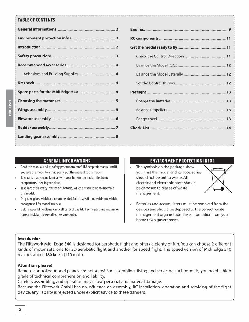
GENERAL INFORMATIONS • Read this manual and its safety precautions carefully! Keep this manual and if
you give the model to a third party, put this manual to the model. • Take care, that you are familiar with your transmitter and all electronic
components, used in your plane. • Take care of all safety instructions of tools, which are you using to assemble
this model. • Only take glues, which are recommended for the specific materials and which
are approved for model business. • Before assembling please check all parts of this kit. If some parts are missing or
have a mistake, please call our service center.
ENVIRONMENT PROTECTION INFOS • The symbols on the package show
you, that the model and its accessories should not be put to waste. All electric and electronic parts should be deposed to places of waste management.
• Batteries and accumulators must be removed from the devices and should be deposed to the correct waste management organisation. Take information from your home town government.
ENGLISH
TABLE OF CONTENTS
General informations ......................................................................2
Environment protection infos ....................................................2
Introduction ........................................................................................2
Safety precautions ...........................................................................3
Recommended accessories ..........................................................4
Adhesives and Building Supplies ............................................4
Kit check ................................................................................................4
Spare parts for the Midi Edge 540 ............................................4
Choosing the motor set .................................................................5
Wings assembly .................................................................................5
Elevator assembly.............................................................................6
Rudder assembly ...............................................................................7
Landing gear assembly ..................................................................8
Engine .....................................................................................................9
RC components ............................................................................... 11
Get the model ready to fly ......................................................... 11
Check the Control Directions ................................................ 11
Balance the Model (C.G.) ......................................................... 12
Balance the Model Laterally .................................................. 12
Set the Control Throws ............................................................ 12
Preflight .............................................................................................. 13
Charge the Batteries ................................................................. 13
Balance Propellers ..................................................................... 13
Range check ................................................................................ 13
Check-List .......................................................................................... 14
IntroductionThe Flitework Midi Edge 540 is designed for aerobatic flight and offers a plenty of fun. You can choose 2 different kinds of motor sets, one for 3D aerobatic flight and another for speed flight. The speed version of Midi Edge 540 reaches about 180 km/h (110 mph).
Attention please!Remote controlled model planes are not a toy! For assembling, flying and servicing such models, you need a high grade of technical comprehension and liability.Careless assembling and operation may cause personal and material damage.Because the Flitework GmbH has no influence on assembly, RC installation, operation and servicing of the flight device, any liability is rejected under explicit advice to these dangers.
3
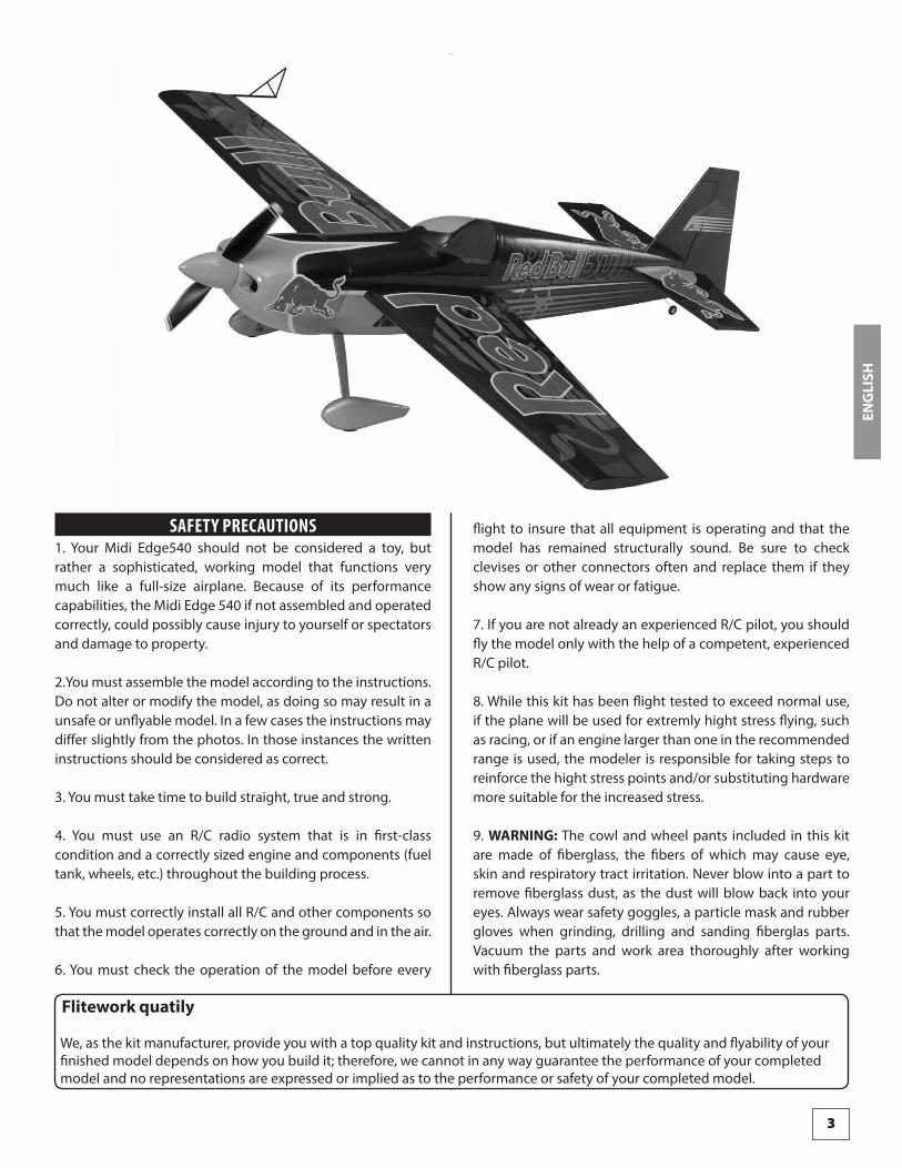
Flitework quatily
We, as the kit manufacturer, provide you with a top quality kit and instructions, but ultimately the quality and flyability of your finished model depends on how you build it; therefore, we cannot in any way guarantee the performance of your completed model and no representations are expressed or implied as to the performance or safety of your completed model.
SAFETY PRECAUTIONS1. Your Midi Edge540 should not be considered a toy, but rather a sophisticated, working model that functions very much like a full-size airplane. Because of its performance capabilities, the Midi Edge 540 if not assembled and operated correctly, could possibly cause injury to yourself or spectators and damage to property.
2.You must assemble the model according to the instructions. Do not alter or modify the model, as doing so may result in a unsafe or unflyable model. In a few cases the instructions may differ slightly from the photos. In those instances the written instructions should be considered as correct.
3. You must take time to build straight, true and strong.
4. You must use an R/C radio system that is in first-class condition and a correctly sized engine and components (fuel tank, wheels, etc.) throughout the building process.
5. You must correctly install all R/C and other components so that the model operates correctly on the ground and in the air.
6. You must check the operation of the model before every
flight to insure that all equipment is operating and that the model has remained structurally sound. Be sure to check clevises or other connectors often and replace them if they show any signs of wear or fatigue.
7. If you are not already an experienced R/C pilot, you should fly the model only with the help of a competent, experienced R/C pilot.
8. While this kit has been flight tested to exceed normal use, if the plane will be used for extremly hight stress flying, such as racing, or if an engine larger than one in the recommended range is used, the modeler is responsible for taking steps to reinforce the hight stress points and/or substituting hardware more suitable for the increased stress.
9. WARNING: The cowl and wheel pants included in this kit are made of fiberglass, the fibers of which may cause eye, skin and respiratory tract irritation. Never blow into a part to remove fiberglass dust, as the dust will blow back into your eyes. Always wear safety goggles, a particle mask and rubber gloves when grinding, drilling and sanding fiberglas parts. Vacuum the parts and work area thoroughly after working with fiberglass parts.
ENGLISH
3
4
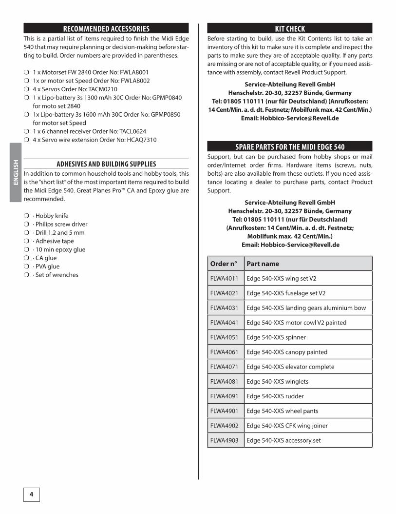
RECOMMENDED ACCESSORIESThis is a partial list of items required to finish the Midi Edge 540 that may require planning or decision-making before star-ting to build. Order numbers are provided in parentheses.
❍ 1 x Motorset FW 2840 Order No: FWLA8001 ❍ 1x or motor set Speed Order No: FWLA8002 ❍ 4 x Servos Order No: TACM0210 ❍ 1 x Lipo-battery 3s 1300 mAh 30C Order No: GPMP0840
for moto set 2840 ❍ 1x Lipo-battery 3s 1600 mAh 30C Order No: GPMP0850
for motor set Speed ❍ 1 x 6 channel receiver Order No: TACL0624 ❍ 4 x Servo wire extension Order No: HCAQ7310
ADHESIVES AND BUILDING SUPPLIESIn addition to common household tools and hobby tools, this is the “short list” of the most important items required to build the Midi Edge 540. Great Planes Pro™ CA and Epoxy glue are recommended.
❍ · Hobby knife ❍ · Philips screw driver ❍ · Drill 1.2 and 5 mm ❍ · Adhesive tape ❍ · 10 min epoxy glue ❍ · CA glue ❍ · PVA glue ❍ · Set of wrenches
KIT CHECKBefore starting to build, use the Kit Contents list to take an inventory of this kit to make sure it is complete and inspect the parts to make sure they are of acceptable quality. If any parts are missing or are not of acceptable quality, or if you need assis-tance with assembly, contact Revell Product Support.
Service-Abteilung Revell GmbH Henschelstr. 20-30, 32257 Bünde, Germany
Tel: 01805 110111 (nur für Deutschland) (Anrufkosten: 14 Cent/Min. a. d. dt. Festnetz; Mobilfunk max. 42 Cent/Min.)
Email: [email protected]
SPARE PARTS FOR THE MIDI EDGE 540Support, but can be purchased from hobby shops or mail order/Internet order firms. Hardware items (screws, nuts, bolts) are also available from these outlets. If you need assis-tance locating a dealer to purchase parts, contact Product Support.
Service-Abteilung Revell GmbH Henschelstr. 20-30, 32257 Bünde, Germany
Tel: 01805 110111 (nur für Deutschland) (Anrufkosten: 14 Cent/Min. a. d. dt. Festnetz;
Mobilfunk max. 42 Cent/Min.) Email: [email protected]
Order n° Part name
FLWA4011 Edge 540-XXS wing set V2
FLWA4021 Edge 540-XXS fuselage set V2
FLWA4031 Edge 540-XXS landing gears aluminium bow
FLWA4041 Edge 540-XXS motor cowl V2 painted
FLWA4051 Edge 540-XXS spinner
FLWA4061 Edge 540-XXS canopy painted
FLWA4071 Edge 540-XXS elevator complete
FLWA4081 Edge 540-XXS winglets
FLWA4091 Edge 540-XXS rudder
FLWA4901 Edge 540-XXS wheel pants
FLWA4902 Edge 540-XXS CFK wing joiner
FLWA4903 Edge 540-XXS accessory set
ENGLISH

5
WINGS ASSEMBLY
Glue the hinges into the slots in wing and aileron, using CA or PVA glue. The glue should be very liquid for better glueing results.
Mount the aileron servo as shown in the picture with 2 screws. Search the center position with servo tester or RC and attach the servo lever parallel to the aileron.
During assembly, look for correct angles and position of the aileron. If the aileron is in neutral position, the servo lever and the linkage should include an angel of 90 degrees.
CHOOSING THE MOTOR SETIf you choose a motor for back mount like the motor from speed motorset, you have to use the shorter motordome which is attached as milling parts in the box of accessories.The longer, just assembled motor dome is only for front mounting of brushless motors with 28mm diameter.
ENGLISH

6
ELEVATOR ASSEMBLY
For testing all matchings put all elevator parts into the section of the fuselage.
mark along the fuselage, using a fine and non permanent marker.Glue the hinges into the slots in wing and aileron, using CA or PVA glue. The glue should be very liquid for better gluing results.
Remove this film along the marks. Be careful and do not hurt the balsa wood below the film.
Before glueing the flap lever to the flap, renove the film carefully from the balsa wood. Use 10 min. Epoxy glue for mounting the levers.
Left wing, lower side Right wing, lower side
After assembly of all aileron linkages, look for the correct center position of aileron and adjust it if necessary. If position is ok, lock all screws, which blue locking agent.
ENGLISH

7
Be carefully and dont hurt the balsa wood below the film. Glue the rudder with 10 min. Epoxy into the slot of body.
Glue the hinges with CA- or PVA glue into the rudder and rudder flaps.Look for easy movement!!
Feel out the frame for rudder servo and open the frame, using a sharp hobby knife. Fix the servo like shown in the picture with servo lever pointing down.
Find the correct highness of rudder lever and mark position.
Glue the elevator in absolut symmetric position in the section of fuselage. Dont forget to put the elevator together with the steel linkage bracket for elevator flaps into the section of the fuselage.Stick the hinges into the elevator using CA or PVA glue. Afterwards glue the flaps to the linkage (epoxy) and hinges (CA or PVA). Take care, that the flaps are not distorted!!
RUDDER ASSEMBLY
Mount the rudder rectangular to the elevator and mark with a fine and non permanent marker along the fuselage.
Remove the covering film along this marks, using a sharp hobby knife.
ENGLISH
8
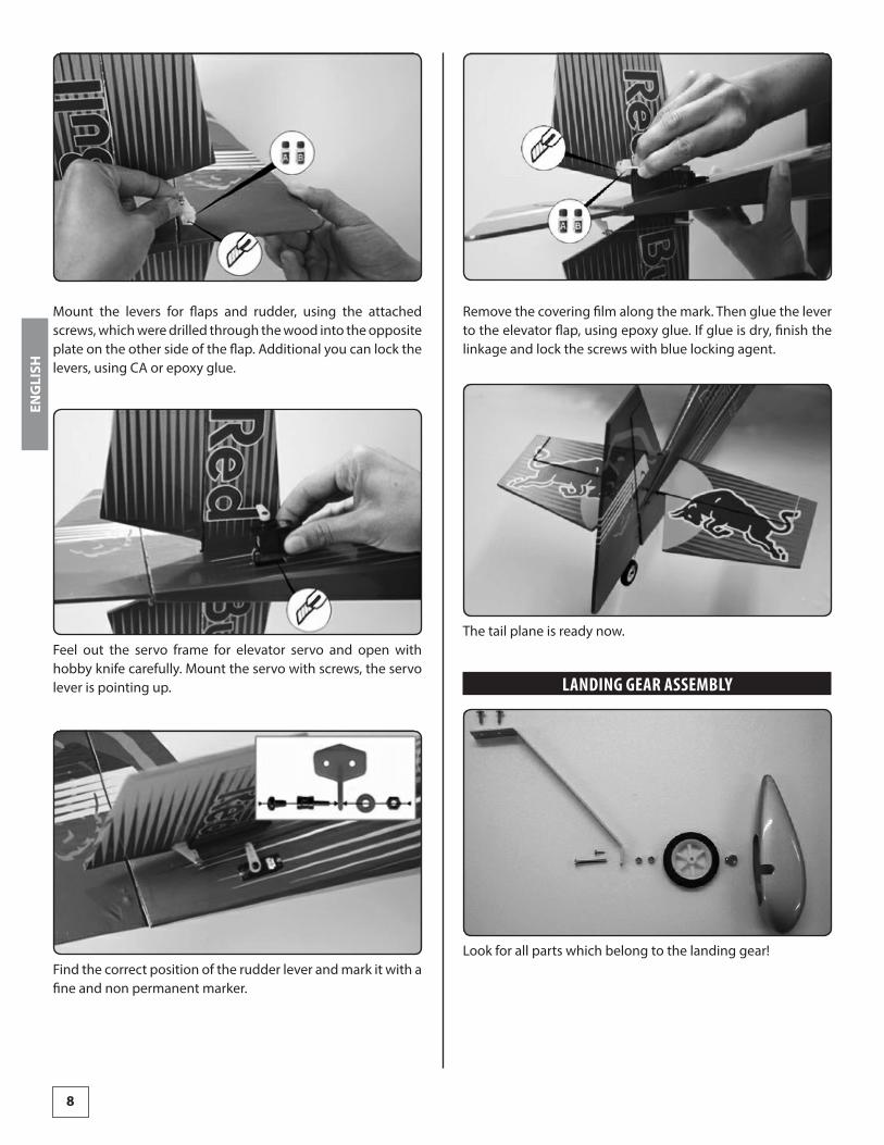
Remove the covering film along the mark. Then glue the lever to the elevator flap, using epoxy glue. If glue is dry, finish the linkage and lock the screws with blue locking agent.
The tail plane is ready now.
LANDING GEAR ASSEMBLY
Look for all parts which belong to the landing gear!
Mount the levers for flaps and rudder, using the attached screws, which were drilled through the wood into the opposite plate on the other side of the flap. Additional you can lock the levers, using CA or epoxy glue.
Feel out the servo frame for elevator servo and open with hobby knife carefully. Mount the servo with screws, the servo lever is pointing up.
Find the correct position of the rudder lever and mark it with a fine and non permanent marker.
ENGLISH

9
ENGINE
Remove the two wood tongues from the motor dome, using a sharp knife.
Put epoxy glue to the motor dome and hook it into the firewall rib. Additional put the two small triangular balsa wood rails to the right and left side of the motor dome.
Countersink the four 3 mm holes with a 5 mm drill
Assemble the landing gear as shown in the picture.
Mount the wheel pant in a position, parallel to the fuselage. Fix the pant with the attached screw.Additional to the screw, you can fix the wheel pants with silicone glue towards the aluminium legs.
At least insert the left and right landing gear into the slot of the fuselage and fix with M3 screws.Dont forget locking agent.
ENGLISH
10
The propeller, not included in the kit should be balanced as good as possible. Assemble prop and spinner. The best result for balancing you can get, if you have the possibility to balance the propeller together with the spinner.
Mount the propeller unit to the motor shaft with the 2 M3 setscrews. Lock with blue locking agent. You can make a little flat spot onto the motor shaft at the position of one setscrew. So you can get more stability.
During mounting the spinner cap do not tighten the screws to strong, because the thread could be damaged.
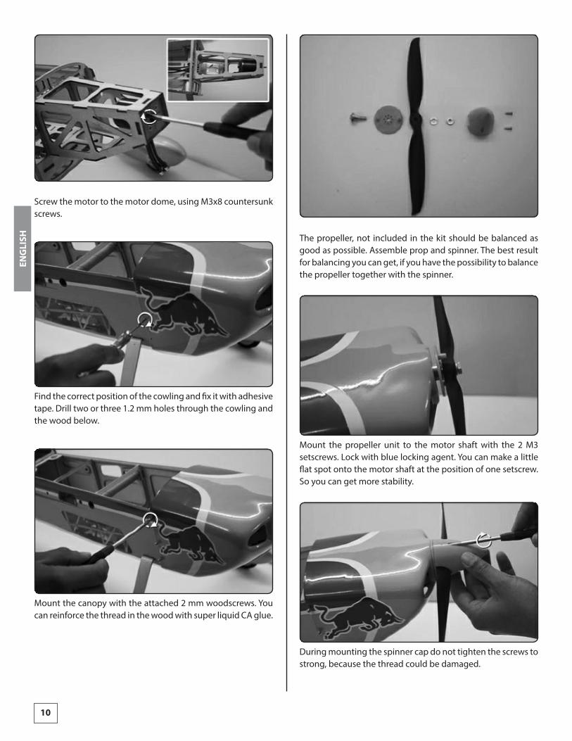
Screw the motor to the motor dome, using M3x8 countersunk screws.
Find the correct position of the cowling and fix it with adhesive tape. Drill two or three 1.2 mm holes through the cowling and the wood below.
Mount the canopy with the attached 2 mm woodscrews. You can reinforce the thread in the wood with super liquid CA glue.
ENGLISH
11
GET THE MODEL READY TO FLY
CHECK THE CONTROL DIRECTIONS
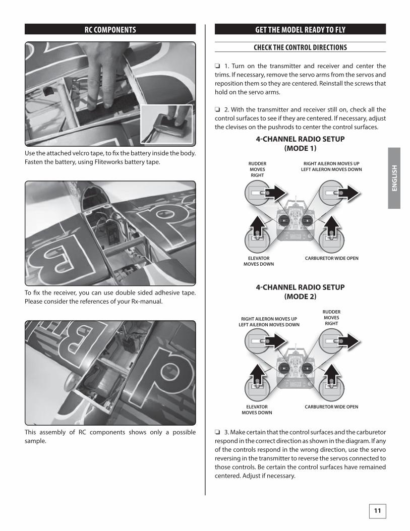
❏ 1. Turn on the transmitter and receiver and center the trims. If necessary, remove the servo arms from the servos and reposition them so they are centered. Reinstall the screws that hold on the servo arms.
❏ 2. With the transmitter and receiver still on, check all the control surfaces to see if they are centered. If necessary, adjust the clevises on the pushrods to center the control surfaces.
CARBURETOR WIDE OPEN
RUDDERMOVESRIGHT
ELEVATORMOVES DOWN
RIGHT AILERON MOVES UPLEFT AILERON MOVES DOWN
4-CHANNEL RADIO SETUP(MODE 1)
ELEVATORMOVES DOWN
RIGHT AILERON MOVES UPLEFT AILERON MOVES DOWN
CARBURETOR WIDE OPEN
RUDDERMOVESRIGHT
4-CHANNEL RADIO SETUP(MODE 2)
❏ 3. Make certain that the control surfaces and the carburetor respond in the correct direction as shown in the diagram. If any of the controls respond in the wrong direction, use the servo reversing in the transmitter to reverse the servos connected to those controls. Be certain the control surfaces have remained centered. Adjust if necessary.
RC COMPONENTS
Use the attached velcro tape, to fi x the battery inside the body. Fasten the battery, using Fliteworks battery tape.
To fi x the receiver, you can use double sided adhesive tape. Please consider the references of your Rx-manual.
This assembly of RC components shows only a possible sample.
ENG
LISH
12
BALANCE THE MODEL (C.G.)
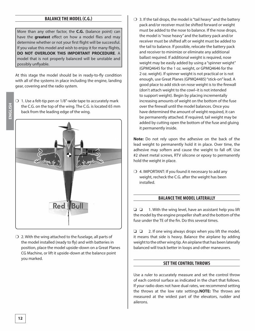
More than any other factor, the C.G. (balance point) can have the greatest effect on how a model flies and may determine whether or not your first flight will be successful. If you value this model and wish to enjoy it for many flights, DO NOT OVERLOOK THIS IMPORTANT PROCEDURE. A model that is not properly balanced will be unstable and possibly unflyable.
At this stage the model should be in ready-to-fly condition with all of the systems in place including the engine, landing gear, covering and the radio system.
❍ 1. Use a felt-tip pen or 1/8"-wide tape to accurately mark the C.G. on the top of the wing. The C.G. is located 65 mm back from the leading edge of the wing.
❍ 2. With the wing attached to the fuselage, all parts of the model installed (ready to fly) and with batteries in position, place the model upside-down on a Great Planes CG Machine, or lift it upside-down at the balance point you marked.
❍ 3. If the tail drops, the model is “tail heavy” and the battery pack and/or receiver must be shifted forward or weight must be added to the nose to balance. If the nose drops, the model is “nose heavy” and the battery pack and/or receiver must be shifted aft or weight must be added to the tail to balance. If possible, relocate the battery pack and receiver to minimize or eliminate any additional ballast required. If additional weight is required, nose weight may be easily added by using a “spinner weight” (GPMQ4645 for the 1 oz. weight, or GPMQ4646 for the 2 oz. weight). If spinner weight is not practical or is not enough, use Great Planes (GPMQ4485) “stick-on” lead. A good place to add stick-on nose weight is to the firewall (don't attach weight to the cowl–it is not intended to support weight). Begin by placing incrementally increasing amounts of weight on the bottom of the fuse over the firewall until the model balances. Once you have determined the amount of weight required, it can be permanently attached. If required, tail weight may be added by cutting open the bottom of the fuse and gluing it permanently inside.
Note: Do not rely upon the adhesive on the back of the lead weight to permanently hold it in place. Over time, the adhesive may softern and cause the weight to fall off. Use #2 sheet metal screws, RTV silicone or epoxy to permanently hold the weight in place.
❍ 4. IMPORTANT: If you found it necessary to add any weight, recheck the C.G. after the weight has been installed.
BALANCE THE MODEL LATERALLY
❏❏ ❏ 1. With the wing level, have an assistant help you lift the model by the engine propeller shaft and the bottom of the fuse under the TE of the fin. Do this several times.
❏❏ ❏ 2. If one wing always drops when you lift the model, it means that side is heavy. Balance the airplane by adding weight to the other wing tip. An airplane that has been laterally balanced will track better in loops and other maneuvers.
SET THE CONTROL THROWS
Use a ruler to accurately measure and set the control throw of each control surface as indicated in the chart that follows. If your radio does not have dual rates, we recommend setting the throws at the low rate settings.NOTE: The throws are measured at the widest part of the elevators, rudder and ailerons.
ENGLISH
13
We recommend the following control surface throws:
Elevator
3D �ight Standard �ight
45°
Up
45°
Down
20°
Up
20°
Down
Rudder 50°
Left
50°
Right
30°
Left
30°
Right
Ailerons 40°
Up
40°
Down
20°
Up
20°
Down
PREFLIGHT
CHARGE THE BATTERIESFollow the battery charging instructions that came with your radio control system to charge the batteries. You should always charge your transmitter and receiver batteries the night before you go flying and at other times as recommended by the radio manufacturer.
NOTE: Checking the condition of your receiver battery pack is highly recommended. All battery packs, whether it's a trusty pack you've just taken out of another model, or a new battery pack you just purchased, should be cycled, noting the discharge capacity. Oftentimes, a weak battery pack can be identified (and a valuable model saved!) by comparing its actual capacity to its rated capacity. Refer to the instructions and recommendations that come with your cycler. If you don't own a battery cycler, perhaps you can have a friend cycle your pack and note the capacity for you. gemessenen. Hier können große Unterschiede auftreten.
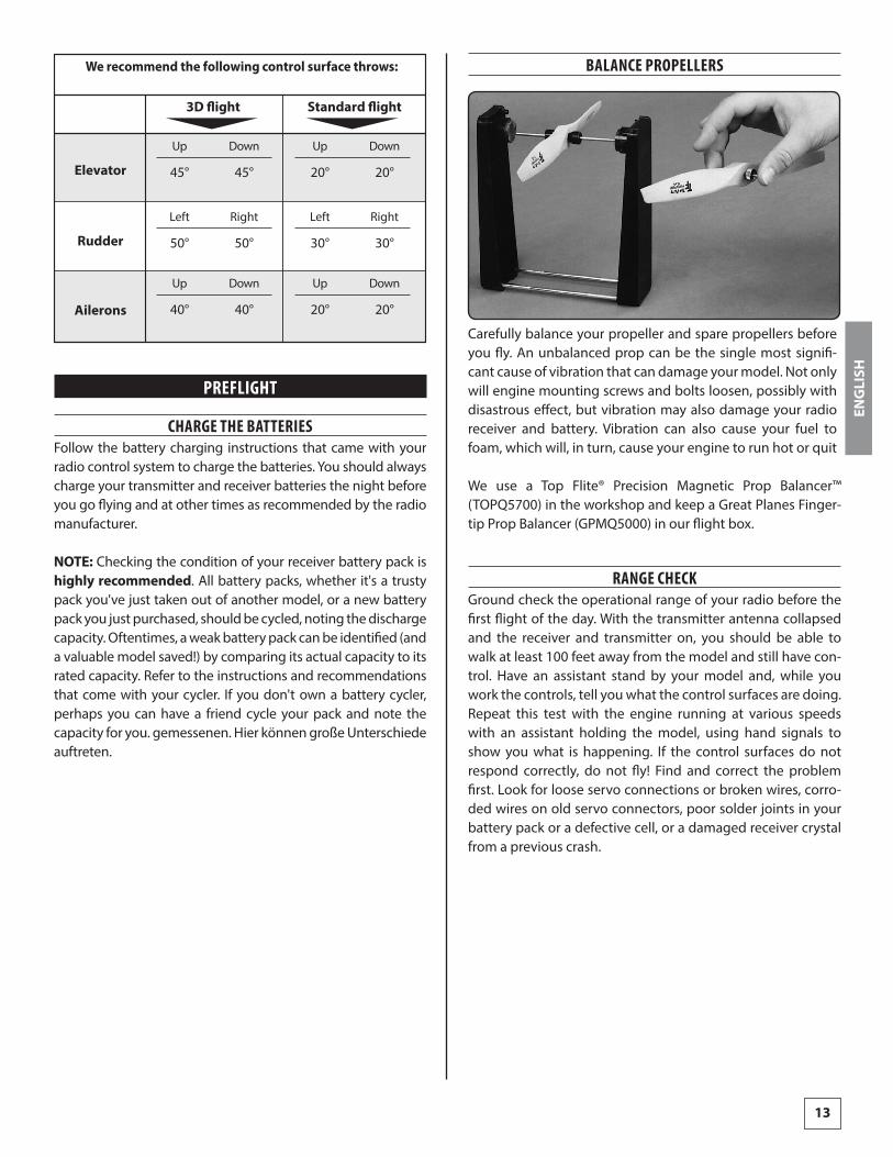
BALANCE PROPELLERS
Carefully balance your propeller and spare propellers before you fly. An unbalanced prop can be the single most signifi-cant cause of vibration that can damage your model. Not only will engine mounting screws and bolts loosen, possibly with disastrous effect, but vibration may also damage your radio receiver and battery. Vibration can also cause your fuel to foam, which will, in turn, cause your engine to run hot or quit
We use a Top Flite® Precision Magnetic Prop Balancer™ (TOPQ5700) in the workshop and keep a Great Planes Finger-tip Prop Balancer (GPMQ5000) in our flight box.
RANGE CHECKGround check the operational range of your radio before the first flight of the day. With the transmitter antenna collapsed and the receiver and transmitter on, you should be able to walk at least 100 feet away from the model and still have con-trol. Have an assistant stand by your model and, while you work the controls, tell you what the control surfaces are doing. Repeat this test with the engine running at various speeds with an assistant holding the model, using hand signals to show you what is happening. If the control surfaces do not respond correctly, do not fly! Find and correct the problem first. Look for loose servo connections or broken wires, corro-ded wires on old servo connectors, poor solder joints in your battery pack or a defective cell, or a damaged receiver crystal from a previous crash.
ENGLISH
14
CHECK-LISTDuring the last few moments of preparation your mind may be elsewhere anticipating the excitement of the first flight. Because of this, you may be more likely to overlook certain checks and procedures that should be performed before the model is flown. To help avoid this, a checklist is provided to make sure these important areas are no overlooked. Many are covered in the instruction manual, so where appropriate, refer to the manual for complete instructions. Be sure to check the items off as they are completed (that's why it's called a check list!).
❍ 1. Check the C.G. according to the measurements provided in the manual.
❍ 2. Be certain the battery and receiver are securely mounted in the fuse. Simply stuffing them into place with foam rubber is not sufficient.
❍ 3. Extend your receiver antenna and make sure it has a strain relief inside the fuselage to keep tension off the solder joint inside the receiver.
❍ 4. Balance your model laterally as explained in the instructions.
❍ 5. Use threadlocking compound to secure critical fasteners such as the set screws that hold the wheel axles to the struts, screws that hold the carburetor arm (if applicable), screw-lock pushrod connectors, etc.
❍ 6. Add a drop of oil to the axles so the wheels will turn freely.
❍ 7. Make sure all hinges are securely glued in place.
❍ 8. Reinforce holes for wood screws with thin CA where appropriate (servo mounting screws, cowl mounting screws, etc.).
❍ 9. Confirm that all controls operate in the correct direction and the throws are set up according to the manual.
❍ 10. Make sure there are silicone retainers on all the clevises and that all servo arms are secured to the servos with the screws included with your radio.
❍ 11. Secure connections between servo wires and Y connectors or servo extensions and the connection between your battery pack and the on/off switch with vinyl tape, heat shrink tubing or special clips suitable for that purpose.
❍ 12. Make sure any servo extension cords you may have used do not interfere with other systems (servo arms, pushrods, etc.).
❍ 13. Balance your propeller (and spare propellers).
❍ 14. Tighten the propeller nut and spinner.
❍ 15. Place your name, address, AMA number and telephone number on or inside your model.
❍ 16. If you wish to photograph your model, do so before your first flight.
❍ 17. Range check your radio when you get to the flying field.
Remember to think.
Have a ball!
But always stay in control and fly in a safe manner.
GOOD LUCK AND GREAT FLYING!
ENGLISH

15
PERSONAL NOTES
ENGLISH

Distributed by www.hobbico.de