FluoroMax P
12
Settrofluorimetro Horiba Jobin Yvon Fluoromax - P Scemi ottici e specifiche tecniche
-
Upload
francesca-porcelli -
Category
Documents
-
view
218 -
download
1
description
operation guide for fluoromax
Transcript of FluoroMax P

Settrofluorimetro Horiba Jobin Yvon Fluoromax - P Scemi ottici e specifiche tecniche

FluoroMax-4 v. 1.1 (20 Dec 2006)
i
FluoroMax®-4 & FluoroMax®-4P
with FluorEssence™
Operation Manual http://www.jobinyvon.com Rev. 1.1

FluoroMax-4 v. 1.1 (20 Dec. 2006) System Description
2-1
2: System Description
Introduction
A spectrofluorometer is an analytical instrument used to measure and record the fluo-rescence of a sample. While recording the fluorescence, the excitation, emission, or both wavelengths may be scanned. With additional accessories, variation of signal with time, temperature, concentration, polarization, or other variables may be monitored.
Basic theory of operation A continuous source of light shines onto an excitation monochromator, which selects a band of wavelengths. This monochromatic excitation light is directed onto a sample, which emits luminescence. The luminescence is directed into a second, emission mono-chromator, which selects a band of wavelengths, and shines them onto a detector. The signal from the detector is reported to a system controller and host computer, where the data can be manipulated and presented, using special software.
Warning: Do not open the instrument without proper training and having read this operation manual. The instrument contains dan-gerous voltages, ultraviolet, visible, and infrared radiation, and fragile light-sources. In addition, tampering with the optical com-ponents can irreversibly damage them.

FluoroMax-4 v. 1.1 (20 Dec. 2006) System Description
2-2
Optical layout
1 Xenon arc-lamp and lamp housing 1a Xenon-lamp power supply 1b Xenon flash lamp (FluoroMax®-4P only) 2 Excitation monochromator 3 Sample compartment 4 Emission monochromator 5 Signal detector (photomultiplier tube and housing) 6 Reference detector (photodiode and current-acquisition module)7 Instrument controller Host computer (not on diagram)
Illuminator (xenon arc-lamp, 1) The continuous light source is a 150-W ozone-free xenon arc-lamp. Light from the lamp is collected by a diamond-turned elliptical mirror, and then focused on the entrance slit of the excitation monochromator. The lamp housing is separated from the excitation monochromator by a quartz window. This vents heat out of the instrument, and protects against the unlikely occurrence of lamp failure.
23
1
4
5
71a
61b

FluoroMax-4 v. 1.1 (20 Dec. 2006) System Description
2-3
Left: motor and gear-box that rotate the mir-ror to switch lamps. Right: Twin sources in the FluoroMax®-4P.
CW lamp
flash lamp
In the FluoroMax®-4P, a second source, a xenon flash lamp, is available also. A FluorEssence™-controlled motor and gearbox rotate the mirror in the illumination area, in order to switch between the CW source and the flash lamp.
Monochromators (2 and 4) The FluoroMax®-4 contains Czerny-Turner monochromators for excitation and emis-sion. The Czerny-Turner design uses all-reflective optics to maintain high resolution over the entire spectral range, and minimize spherical aberrations and re-diffraction.
Gratings The essential part of a monochromator is a reflection grating. A grating disperses the incident light by means of its vertical grooves. A spectrum is obtained by rotating the gratings, and recording the intensity values at each wavelength. The gratings in the Fluoro-Max®-4 contain 1200 grooves mm–1, and are blazed at 330 nm (excitation) and 500 nm (emission). Blazing is etching the grooves at a particular angle, to optimize the grating’s reflectivity in a par-ticular spectral region. The wavelengths selected are optimal for excitation in the UV and visible, and for emission in the high-UV to near-IR. Each grating is coated with MgF2 for protection against oxidation. The system uses a direct drive for each grating, to scan the spectrum at up to 200 nm s–1, with accu-racy better than 0.5 nm, and repeatability of 0.3 nm.
Slits The entrance and exit ports of each monochromator have continuously adjustable slits controlled by FluorEssence™. The width of the slits on the excitation monochromator determines the bandpass of light incident on the sample. The emission monochroma-
Excitation monochromator. Emission monochromator.

FluoroMax-4 v. 1.1 (20 Dec. 2006) System Description
2-4
tor’s slits control the intensity of the fluorescence signal recorded by the signal detec-tor. When setting slit width, the trade-off is intensity of signal versus spectral resolu-tion. The wider the slits are, the more light falls on the sample and detector, but the resolution decreases. The narrower the slits are, the higher the resolution gets, but at the expense of signal. Set the slits for intensity toward the higher end of the detector’s lin-ear response, with sharp-enough resolution to discern desired spectral features. Slits may be set in bandpass units, or the physical width of the slit (mm). Under band-pass units, each monochromator’s slits are set simultaneously, for the bandpass is de-termined by the dispersion of the monochromator: bandpass (in nm) = slit width (in mm) × dispersion (in nm mm–1) The dispersion of FluoroMax®-4 monochromators is 4.25 nm mm–1 for gratings with 1200 grooves mm–1. Below is a table showing standard slit widths with their corre-sponding bandpasses. Slit width (mm) Bandpass (nm) Rounded bandpass (nm) 0.50 2.125 2 1.175 4.994 5 2.00 8.500 8.5
Shutters An excitation shutter, standard on the FluoroMax®-4, is located just after the excitation monochromator’s exit slit. The shutter protects samples from photobleaching or photo-degradation from prolonged exposure to the light source. FluorEssence™ controls the shutter, and can set the shutter to automatic or photobleach modes. An emission shutter is an optional accessory, placed just before the emission monochromator’s entrance, and protects the detector from bright light.
Sample compartment (3)
A toroidal mirror focuses the beam from the excitation monochromator on the sample. About 8% of this excitation light is split off, using a beam-splitter, to the reference pho-todiode. Fluorescence from the sample is then collected and directed to the emission spectrometer. The sample compartment accommodates various optional accessories, as well as fiber-optic bundles to take the excitation beam to a remote sample (or the MicroMax), and return the emission beam to the emission monochromator. See Chapter 7 for a list of accessories.
Caution: Operation of the instrument when the excita-tion shutter is disabled may expose the user to exces-sive light. Wear light-blocking goggles or face-shield, and light-blocking clothing and gloves.
FluoroMax-4 v. 1.1 (20 Dec. 2006) System Description
2-5
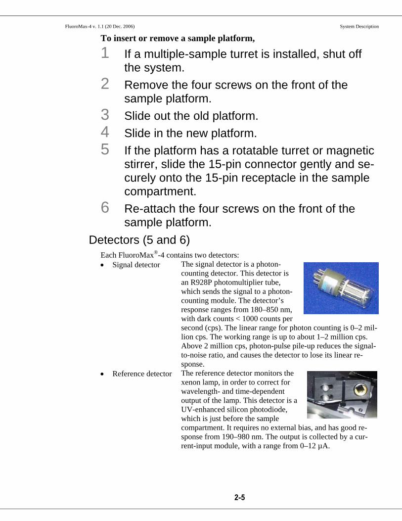
To insert or remove a sample platform,
1 If a multiple-sample turret is installed, shut off the system.
2 Remove the four screws on the front of the sample platform.
3 Slide out the old platform. 4 Slide in the new platform. 5 If the platform has a rotatable turret or magnetic
stirrer, slide the 15-pin connector gently and se-curely onto the 15-pin receptacle in the sample compartment.
6 Re-attach the four screws on the front of the sample platform.
Detectors (5 and 6) Each FluoroMax®-4 contains two detectors: • Signal detector The signal detector is a photon-
counting detector. This detector is an R928P photomultiplier tube, which sends the signal to a photon-counting module. The detector’s response ranges from 180–850 nm, with dark counts < 1000 counts per second (cps). The linear range for photon counting is 0–2 mil-lion cps. The working range is up to about 1–2 million cps. Above 2 million cps, photon-pulse pile-up reduces the signal-to-noise ratio, and causes the detector to lose its linear re-sponse.
• Reference detector The reference detector monitors the xenon lamp, in order to correct for wavelength- and time-dependent output of the lamp. This detector is a UV-enhanced silicon photodiode, which is just before the sample compartment. It requires no external bias, and has good re-sponse from 190–980 nm. The output is collected by a cur-rent-input module, with a range from 0–12 µA.

FluoroMax-4 v. 1.1 (20 Dec. 2006) System Description
2-6
Lamp power supply (1a).
Both the reference and signal detectors have correction-factor files run for them, to cor-rect for wavelength dependencies of each optical component. The files are created at HORIBA Jobin Yvon Inc. for every instrument, and may be applied to data through FluorEssence™. See Chapter 8 for more details.
Electronics and controllers (1a and 7)
The right rear and bottom of the Fluoro-Max®-4 houses the electronics for running the lamp, instrument, scans, and measure-ments.
Slave-controller electronics above the optical platform
Electronics underneath the optical platform.
Excitation monochromator control board
Emission monochro-mator control board Sample
compartment
Excitation mono-chromator direct drive
Emission monochro-mator direct drive
Emission PMT
Accessory control board may be here
Photon-counting module for PMT
AC power, DC sup-plies, and filters
FluoroMax-4 v. 1.1 (20 Dec. 2006) System Description
2-7
• Xenon-lamp power
supply (1a) This supply is a tunable 180-W-maximum power supply. It supplies a large start-up voltage to the 150-W xenon lamp, then holds the lamp steady at 12 V. The voltage is filtered, to stabilize the illumination as much as possible. The lamp is started with the left rocker-switch on the front-right panel of the instrument.
• Slave controller Located on the right rear of the FluoroMax®-4, it is com-posed of a dedicated motherboard that holds control and data-acquisition cards. A set of drivers is held in firm-ware on the motherboard, for low-level instrument con-trol. This controller is linked to the host computer via a null modem serial link. The controller houses the CTI (counter, timer, integrator) card, for all instrument con-trol and data-acquisition.
• Monochromator 180F boards and optional ac-cessory board
Underneath the optical platform, there are several control boards. They control the monochromators and any op-tional accessories connected to the sample compartment. See Chapter 12 for more details.
Computer system and software (not on diagram) Not shown on the schematic is the host computer with FluorEssence™ software. The technical specifications chapter lists the computer requirements. An optional printer or network card is useful for printing. FluorEssence™ software for Windows® controls all interaction with the spectrofluorometer. For information on FluorEssence™, see the FluorEssence™ User’s Guide and the on-line help files within FluorEssence™.

FluoroMax-4 v. 1.1 (20 Dec. 2006) Technical Specifications
11-1
11: Technical Specifications Each FluoroMax®-4 system consists of: • An excitation source • An excitation monochromator • A sampling module with reference detector • An emission monochromator • An emission detector. A FluoroMax®-4P system adds: • A motorized mirror to change between light sources • A pulsed xenon lamp • A phosphorimeter-control module Each system is controlled by an IBM-PC-compatible computer, and may include a printer for hard-copy documentation. The details and specifications for each component of the FluoroMax®-4 and Fluoro-Max®-4P series of spectrometers follow.

FluoroMax-4 v. 1.1 (20 Dec. 2006) Technical Specifications
11-2
Spectrofluorometer system
FluoroMax®-4 and FluoroMax®-4P The FluoroMax®-4 and FluoroMax®-4P spectrofluorometers consist of components controlled by the specialized software. The basic (standard) FluoroMax®-4 and Fluoro-Max®-4P spectrofluorometer systems contain of the following components:
Excitation Source 150-W xenon, continuous output, ozone-free lamp
Optics All-reflective, for focusing at all wavelengths and precise imag-ing for microsamples.
Dispersion 4.25 nm mm–1
Monochromators Single-grating excitation and emission spectrometers (standard). Monochromators are f/3.5 Czerny-Turner design with classi-cally-ruled gratings and all-reflective optics, using 1200-grooves/mm gratings:
Resolution 0.3 nm Maximum scan speed 80 nm s–1 Accuracy ±0.5 nm Step Size 0.0625–100 nm
Range 0–950 nm (physical) Gratings Excitation 330-nm blaze (220–600 nm optical range) Emission 500-nm blaze (290–850 nm optical range)
Sample Module The sample module also has a removable gap-bed assembly for sampling accessory replacement.
Detectors • Calibrated photodiode for excitation reference correction from 200–980 nm.
• Emission detector is an R928P for high sensitivity in photon-counting mode (200–850 nm). High voltage = 950 V, linear-ity to 2 × 10⁶ counts s–1, < 1000 dark counts s–1.
Sensitivity Double-distilled, de-ionized, ICP-grade water-Raman scan 3000:1 S/N at 397 nm, 5-nm bandpass, 1-s integration time, background noise first standard deviation at 450 nm. 400 000 counts s–1 using these conditions.
Excitation shutter Computer-controlled
Integration time 0.001–160 s
Slit width 0–30 nm bandpass, continuously adjustable via host computer
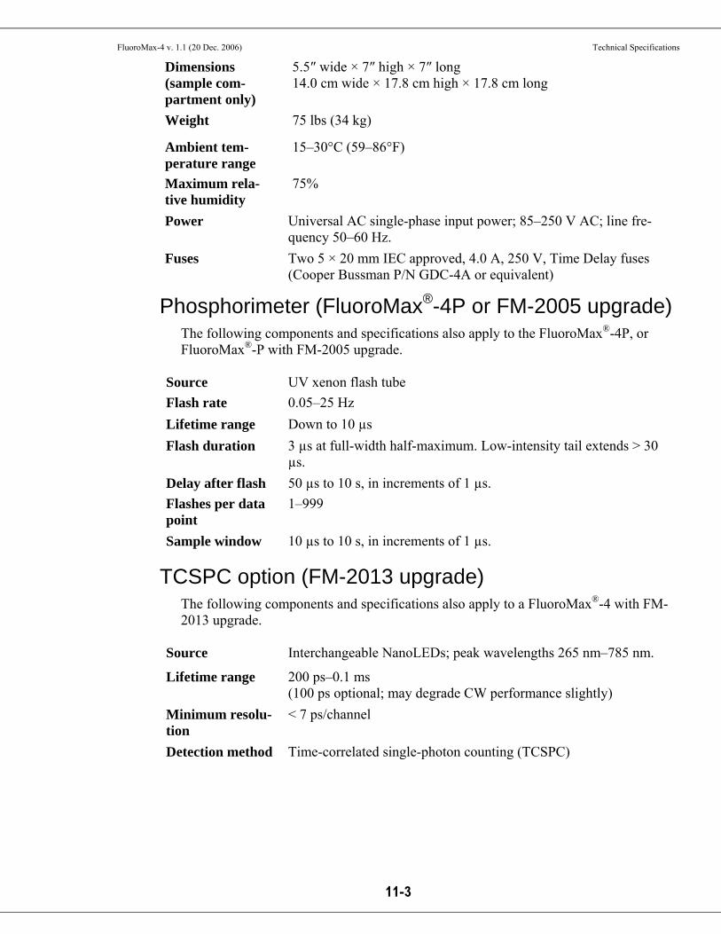
Dimensions (in-strument)
32⅝″ wide × 11⅛″ high × 19¾″ deep 82.9 cm wide × 28.3 cm high × 50.2 cm long Height needed to open sample-compartment lid: 20½″; 52.1 cm
FluoroMax-4 v. 1.1 (20 Dec. 2006) Technical Specifications
11-3
Dimensions (sample com-partment only)
5.5″ wide × 7″ high × 7″ long 14.0 cm wide × 17.8 cm high × 17.8 cm long
Weight 75 lbs (34 kg)
Ambient tem-perature range
15–30°C (59–86°F)
Maximum rela-tive humidity
75%
Power Universal AC single-phase input power; 85–250 V AC; line fre-quency 50–60 Hz.
Fuses Two 5 × 20 mm IEC approved, 4.0 A, 250 V, Time Delay fuses (Cooper Bussman P/N GDC-4A or equivalent)
Phosphorimeter (FluoroMax®-4P or FM-2005 upgrade) The following components and specifications also apply to the FluoroMax®-4P, or FluoroMax®-P with FM-2005 upgrade.
Source UV xenon flash tube Flash rate 0.05–25 Hz Lifetime range Down to 10 µs Flash duration 3 µs at full-width half-maximum. Low-intensity tail extends > 30
µs. Delay after flash 50 µs to 10 s, in increments of 1 µs. Flashes per data point
1–999
Sample window 10 µs to 10 s, in increments of 1 µs.
TCSPC option (FM-2013 upgrade) The following components and specifications also apply to a FluoroMax®-4 with FM-2013 upgrade.
Source Interchangeable NanoLEDs; peak wavelengths 265 nm–785 nm.
Lifetime range 200 ps–0.1 ms (100 ps optional; may degrade CW performance slightly)
Minimum resolu-tion
< 7 ps/channel
Detection method Time-correlated single-photon counting (TCSPC)