Fluke MDA-510 and MDA-550 Motor Drive Analyzer
10
TECHNICAL DATA Fluke MDA-510 and MDA-550 Motor Drive Analyzer Simplify complex motor-drive troubleshooting with guided test setups and automated drive measurements that provide reliable, repeatable test results. The new Fluke MDA 510 and MDA 550 Motor-Drive Analyzers save time and eliminate the hassle of setting up complex measurements, while simplifying the troubleshooting process. Simply select a test and the step-by-step guided measurements show you where to make voltage and current connections, while the preset measurement profiles ensure you will capture all the data you need for each critical motor-drive section—from the input to the output, the DC bus, and the motor itself. From basic to advanced measurements, the MDA-500 Series has you covered, and with a built-in report generator you can quickly and easily generate as-found, and as-left reports with confidence. The MDA-510 and MDA-550 are the ideal portable motor-drive analysis test tools, and can help safely locate and troubleshoot typical problems on inverter type motor-drive systems. • Measure key motor-drive parameters including voltage, current, DC Bus voltage level and AC ripple, voltage and current unbalance and harmonics (MDA-550), voltage modulation, and motor shaft voltage discharges (MDA-550). • Perform extended harmonics measurements to identify the effects of low and high order harmonics on your electrical power system. • Conduct guided measurements for motor-drive input, DC bus, drive output, motor input and shaft measurements (MDA-550) with graphical step-by-step voltage and current connection diagrams. • Use simplified measurement setup with preset measurement profiles to automatically trigger data collection based on the chosen test procedure. • Create reports quickly and easily that are perfect for documenting troubleshooting and collaborative work with others. • Measure additional electrical parameters with full 500 MHz oscilloscope, meter and recording capability for complete range of electrical and electronic measurement on industrial systems. KEY MEASUREMENTS Inverter output voltage, DC bus voltage and ripple voltage, harmonics, unbalance THREE POWERFUL TEST TOOLS IN ONE Motor-drive analyzer, waveform analyzer and recording data logger all in one HIGHEST SAFETY RATING IN THE INDUSTRY 600 V CAT IV/1000 V CAT III rated for use at the service entrance and downstream
Transcript of Fluke MDA-510 and MDA-550 Motor Drive Analyzer
TECHNICAL DATA
Fluke MDA-510 and MDA-550 Motor Drive Analyzer
Simplify complex motor-drive troubleshooting with guided test setups and automated drive measurements that provide reliable, repeatable test results.The new Fluke MDA 510 and MDA 550 Motor-Drive Analyzers save time and eliminate the hassle of setting up complex measurements, while simplifying the troubleshooting process. Simply select a test and the step-by-step guided measurements show you where to make voltage and current connections, while the preset measurement profiles ensure you will capture all the data you need for each critical motor-drive section—from the input to the output, the DC bus, and the motor itself. From basic to advanced measurements, the MDA-500 Series has you covered, and with a built-in report generator you can quickly and easily generate as-found, and as-left reports with confidence.
The MDA-510 and MDA-550 are the ideal portable motor-drive analysis test tools, and can help safely locate and troubleshoot typical problems on inverter type motor-drive systems.
• Measure key motor-drive parameters including voltage, current, DC Bus voltage level and AC ripple, voltage and current unbalance and harmonics (MDA-550), voltage modulation, and motor shaft voltage discharges (MDA-550).
• Perform extended harmonics measurements to identify the effects of low and high order harmonics on your electrical power system.
• Conduct guided measurements for motor-drive input, DC bus, drive output, motor input and shaft measurements (MDA-550)with graphical step-by-step voltage and current connection diagrams.
• Use simplified measurement setup with preset measurement profiles to automatically trigger data collection based on the chosen test procedure.
• Create reports quickly and easily that are perfect for documenting troubleshooting and collaborative work with others.
• Measure additional electrical parameters with full 500 MHz oscilloscope, meter and recording capability for complete range of electrical and electronic measurement on industrial systems.
KEY MEASUREMENTSInverter output voltage, DC bus voltage and ripple voltage, harmonics, unbalance
THREE POWERFUL TEST TOOLS IN ONEMotor-drive analyzer, waveform analyzer and recording data logger all in one
HIGHEST SAFETY RATING IN THE INDUSTRY600 V CAT IV/1000 V CAT III rated for use at the service entrance and downstream
2 Fluke Corporation Fluke MDA-510 and MDA-550 Motor Drive Analyzer
The Fluke MDA-510 and MDA-550 Motor Drive Analyzers use guided test measurements to make analysis easier than ever
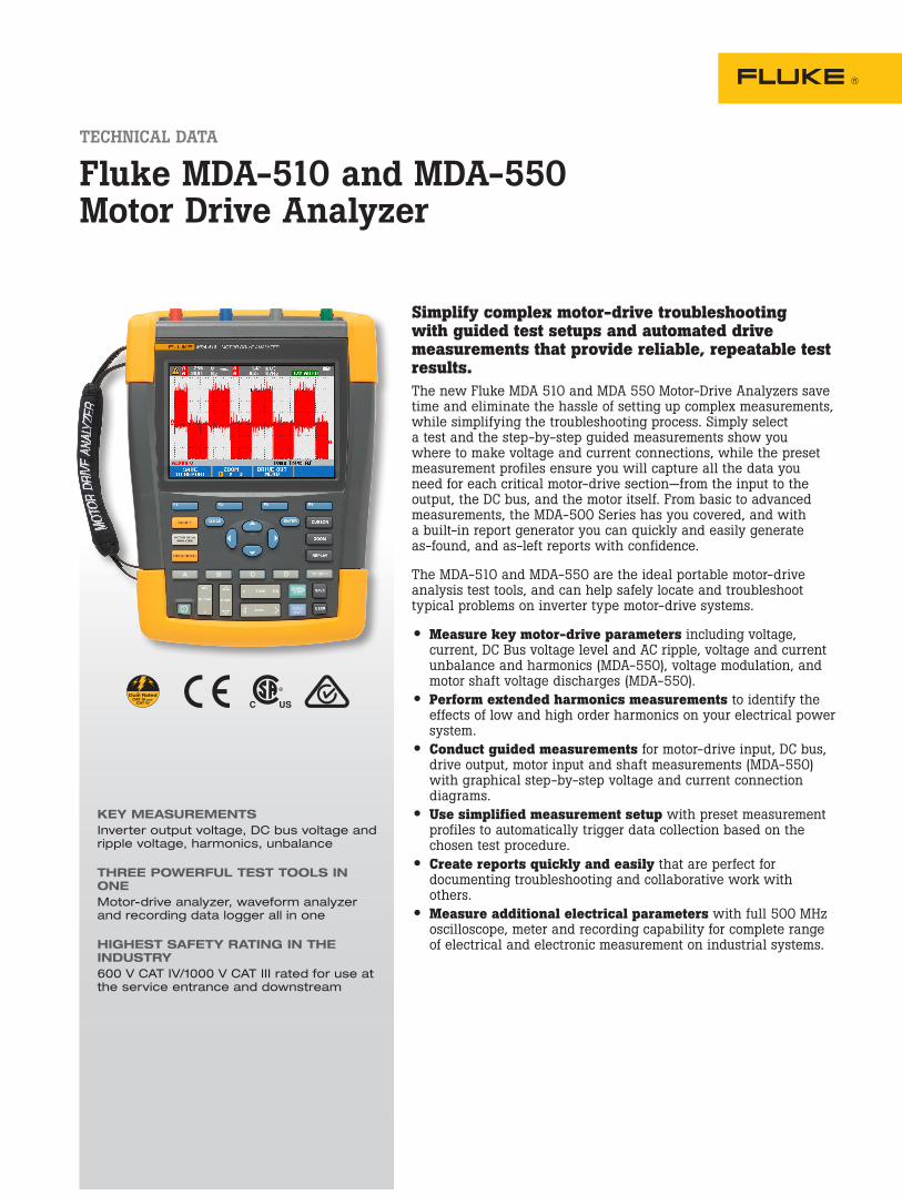
Drive inputMeasure input voltage and current to quickly see whether values are within acceptable limits by comparing the drive’s nominal rated voltage to the actual supplied voltage. Then, check the input current to determine if the current is within the maximum rating and the conductors are suitably sized. You can also check whether the harmonic distortion is within an acceptable level by visu-ally inspecting the waveform shape or by viewing the harmonics spectrum screen (MDA-550) which shows both the total harmonic distortion and individual harmonics.
Voltage and current unbalanceCheck the voltage unbalance at the input terminals so you can ensure the phase unbalance is not too high (> 6-8 %), and that the phase rotation is correct. You can also check the current unbalance, as excessive unbalance may indicate a drive rectifier problem.
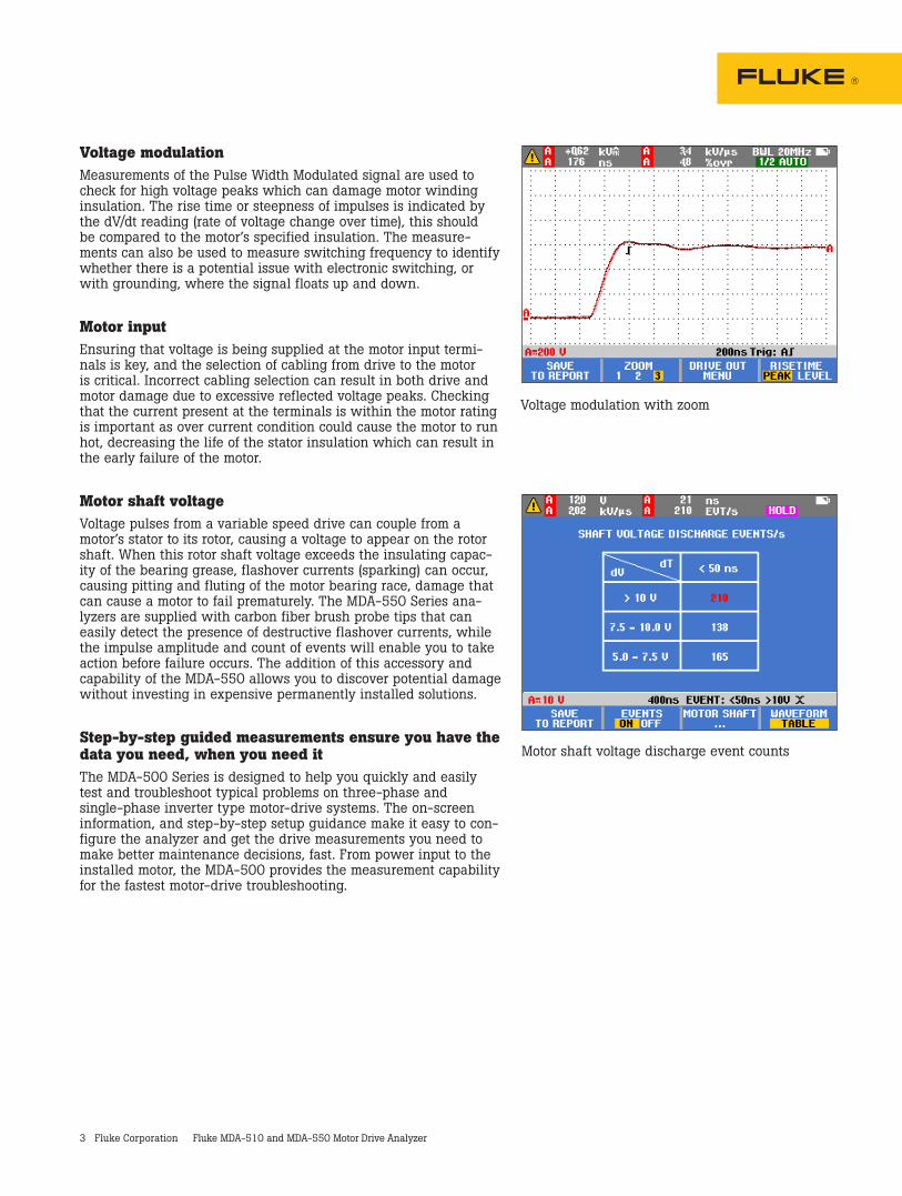
Extended harmonic measurementsExcessive harmonics are not just a threat to your rotating machines but also to other equipment connected to the electrical power system. The MDA-550 provides the ability to discover the harmon-ics of the motor-drive but can also discover the possible effects of inverter switching electronics. The MDA-550 has three harmonic ranges, 1st to 51st Harmonics, 1 to 9 kHz and 9 kHz to 150 kHz giving the ability to detect any harmonic pollution problems.
DC busIn a motor-drive the conversion of AC to DC inside the drive is critical, having the correct voltage and adequate smoothing with low ripple is required for the best drive performance. High ripple voltage may be an indicator of failed capacitors or incorrect sizing of the connected motor. The record function of the MDA-500 Series can be used to check DC bus performance dynamically in the oper-ating mode while a load is applied.
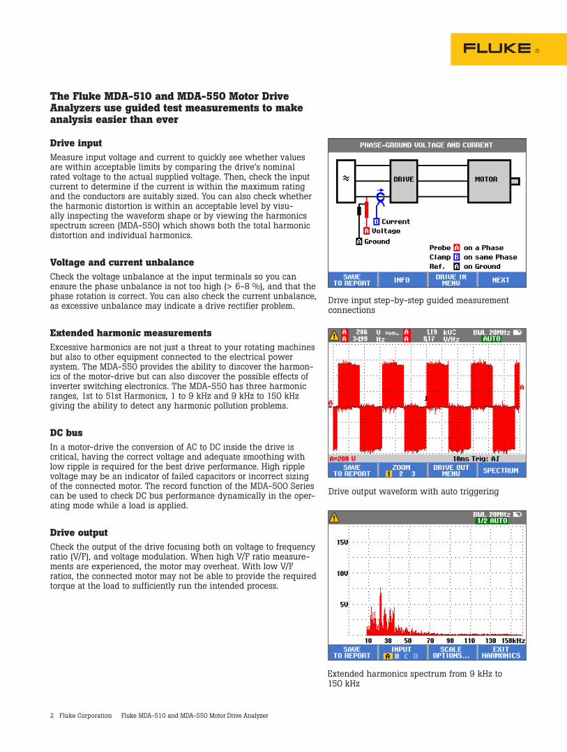
Drive outputCheck the output of the drive focusing both on voltage to frequency ratio (V/F), and voltage modulation. When high V/F ratio measure-ments are experienced, the motor may overheat. With low V/F ratios, the connected motor may not be able to provide the required torque at the load to sufficiently run the intended process.
Drive input step-by-step guided measurement connections
Drive output waveform with auto triggering
Extended harmonics spectrum from 9 kHz to 150 kHz
3 Fluke Corporation Fluke MDA-510 and MDA-550 Motor Drive Analyzer
Voltage modulationMeasurements of the Pulse Width Modulated signal are used to check for high voltage peaks which can damage motor winding insulation. The rise time or steepness of impulses is indicated by the dV/dt reading (rate of voltage change over time), this should be compared to the motor’s specified insulation. The measure-ments can also be used to measure switching frequency to identify whether there is a potential issue with electronic switching, or with grounding, where the signal floats up and down.
Motor inputEnsuring that voltage is being supplied at the motor input termi-nals is key, and the selection of cabling from drive to the motor is critical. Incorrect cabling selection can result in both drive and motor damage due to excessive reflected voltage peaks. Checking that the current present at the terminals is within the motor rating is important as over current condition could cause the motor to run hot, decreasing the life of the stator insulation which can result in the early failure of the motor.
Motor shaft voltageVoltage pulses from a variable speed drive can couple from a motor’s stator to its rotor, causing a voltage to appear on the rotor shaft. When this rotor shaft voltage exceeds the insulating capac-ity of the bearing grease, flashover currents (sparking) can occur, causing pitting and fluting of the motor bearing race, damage that can cause a motor to fail prematurely. The MDA-550 Series ana-lyzers are supplied with carbon fiber brush probe tips that can easily detect the presence of destructive flashover currents, while the impulse amplitude and count of events will enable you to take action before failure occurs. The addition of this accessory and capability of the MDA-550 allows you to discover potential damage without investing in expensive permanently installed solutions.
Step-by-step guided measurements ensure you have the data you need, when you need itThe MDA-500 Series is designed to help you quickly and easily test and troubleshoot typical problems on three-phase and single-phase inverter type motor-drive systems. The on-screen information, and step-by-step setup guidance make it easy to con-figure the analyzer and get the drive measurements you need to make better maintenance decisions, fast. From power input to the installed motor, the MDA-500 provides the measurement capability for the fastest motor-drive troubleshooting.
Voltage modulation with zoom
Motor shaft voltage discharge event counts
4 Fluke Corporation Fluke MDA-510 and MDA-550 Motor Drive Analyzer
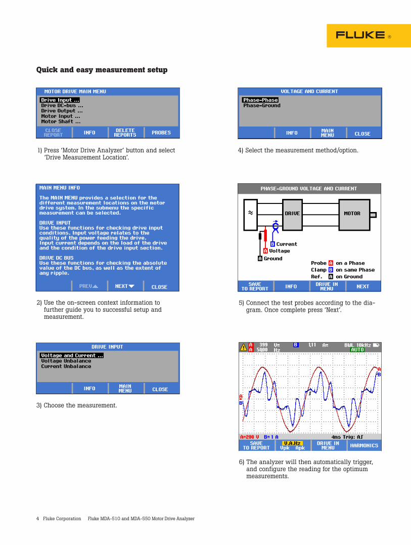
Quick and easy measurement setup
1) Press ‘Motor Drive Analyzer’ button and select ‘Drive Measurement Location’.
2) Use the on-screen context information to further guide you to successful setup and measurement.
3) Choose the measurement.
4) Select the measurement method/option.
5) Connect the test probes according to the dia-gram. Once complete press ‘Next’.
6) The analyzer will then automatically trigger, and configure the reading for the optimum measurements.
5 Fluke Corporation Fluke MDA-510 and MDA-550 Motor Drive Analyzer
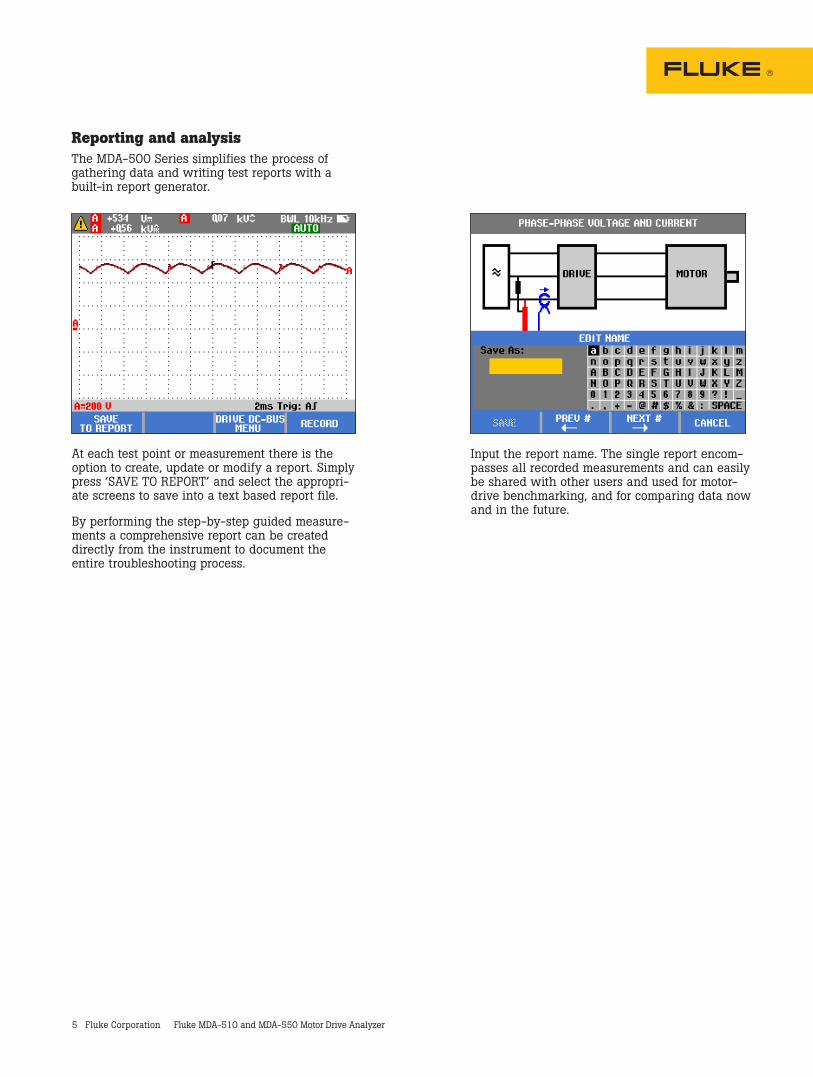
Reporting and analysisThe MDA-500 Series simplifies the process of gathering data and writing test reports with a built-in report generator.
At each test point or measurement there is the option to create, update or modify a report. Simply press ‘SAVE TO REPORT’ and select the appropri-ate screens to save into a text based report file.
By performing the step-by-step guided measure-ments a comprehensive report can be created directly from the instrument to document the entire troubleshooting process.
Input the report name. The single report encom-passes all recorded measurements and can easily be shared with other users and used for motor-drive benchmarking, and for comparing data now and in the future.
6 Fluke Corporation Fluke MDA-510 and MDA-550 Motor Drive Analyzer
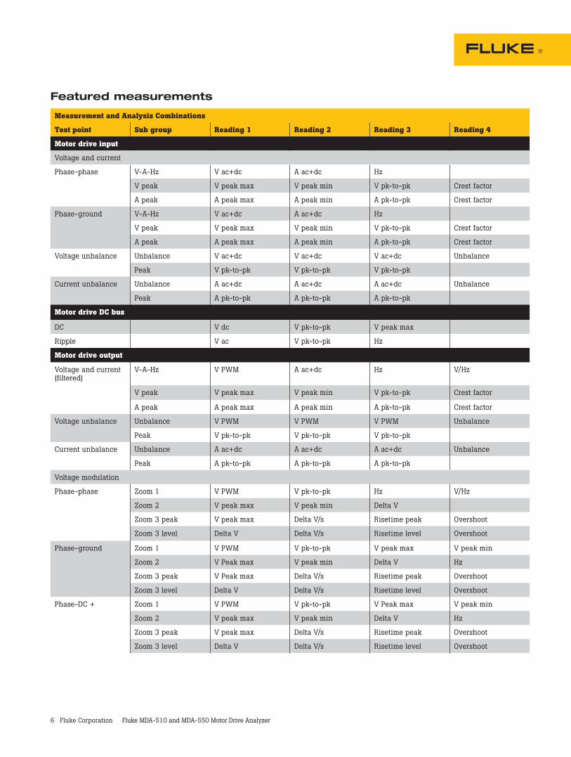
Featured measurements
Measurement and Analysis Combinations
Test point Sub group Reading 1 Reading 2 Reading 3 Reading 4
Motor drive input
Voltage and current
Phase-phase
V-A-Hz V ac+dc A ac+dc Hz
V peak V peak max V peak min V pk-to-pk Crest factor
A peak A peak max A peak min A pk-to-pk Crest factor
Phase-ground
V-A-Hz V ac+dc A ac+dc Hz
V peak V peak max V peak min V pk-to-pk Crest factor
A peak A peak max A peak min A pk-to-pk Crest factor
Voltage unbalance
Unbalance V ac+dc V ac+dc V ac+dc Unbalance
Peak V pk-to-pk V pk-to-pk V pk-to-pk
Current unbalance
Unbalance A ac+dc A ac+dc A ac+dc Unbalance
Peak A pk-to-pk A pk-to-pk A pk-to-pk
Motor drive DC bus
DC V dc V pk-to-pk V peak max
Ripple V ac V pk-to-pk Hz
Motor drive output
Voltage and current (filtered)
V-A-Hz V PWM A ac+dc Hz V/Hz
V peak V peak max V peak min V pk-to-pk Crest factor
A peak A peak max A peak min A pk-to-pk Crest factor
Voltage unbalance
Unbalance V PWM V PWM V PWM Unbalance
Peak V pk-to-pk V pk-to-pk V pk-to-pk
Current unbalance
Unbalance A ac+dc A ac+dc A ac+dc Unbalance
Peak A pk-to-pk A pk-to-pk A pk-to-pk
Voltage modulation
Phase-phase
Zoom 1 V PWM V pk-to-pk Hz V/Hz
Zoom 2 V peak max V peak min Delta V
Zoom 3 peak V peak max Delta V/s Risetime peak Overshoot
Zoom 3 level Delta V Delta V/s Risetime level Overshoot
Phase-ground
Zoom 1 V PWM V pk-to-pk V peak max V peak min
Zoom 2 V Peak max V peak min Delta V Hz
Zoom 3 peak V Peak max Delta V/s Risetime peak Overshoot
Zoom 3 level Delta V Delta V/s Risetime level Overshoot
Phase-DC +
Zoom 1 V PWM V pk-to-pk V Peak max V peak min
Zoom 2 V peak max V peak min Delta V Hz
Zoom 3 peak V peak max Delta V/s Risetime peak Overshoot
Zoom 3 level Delta V Delta V/s Risetime level Overshoot
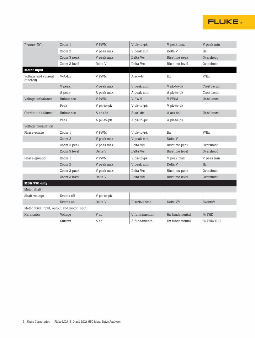
7 Fluke Corporation Fluke MDA-510 and MDA-550 Motor Drive Analyzer
Phase-DC - Zoom 1 V PWM V pk-to-pk V peak max V peak min
Zoom 2 V peak max V peak min Delta V Hz
Zoom 3 peak V peak max Delta V/s Risetime peak Overshoot
Zoom 3 level Delta V Delta V/s Risetime level Overshoot
Motor input
Voltage and current (filtered)
V-A-Hz V PWM A ac+dc Hz V/Hz
V peak V peak max V peak min V pk-to-pk Crest factor
A peak A peak max A peak min A pk-to-pk Crest factor
Voltage unbalance Unbalance V PWM V PWM V PWM Unbalance
Peak V pk-to-pk V pk-to-pk V pk-to-pk
Current unbalance Unbalance A ac+dc A ac+dc A ac+dc Unbalance
Peak A pk-to-pk A pk-to-pk A pk-to-pk
Voltage modulation
Phase-phase Zoom 1 V PWM V pk-to-pk Hz V/Hz
Zoom 2 V peak max V peak min Delta V
Zoom 3 peak V peak max Delta V/s Risetime peak Overshoot
Zoom 3 level Delta V Delta V/s Risetime level Overshoot
Phase-ground Zoom 1 V PWM V pk-to-pk V peak max V peak min
Zoom 2 V peak max V peak min Delta V Hz
Zoom 3 peak V peak max Delta V/s Risetime peak Overshoot
Zoom 3 level Delta V Delta V/s Risetime level Overshoot
MDA 550 only
Motor shaft
Shaft voltage Events off V pk-to-pk
Events on Delta V Rise/fall time Delta V/s Events/s
Motor drive input, output and motor input
Harmonics Voltage V ac V fundamental Hz fundamental % THD
Current A ac A fundamental Hz fundamental % THD/TDD
8 Fluke Corporation Fluke MDA-510 and MDA-550 Motor Drive Analyzer
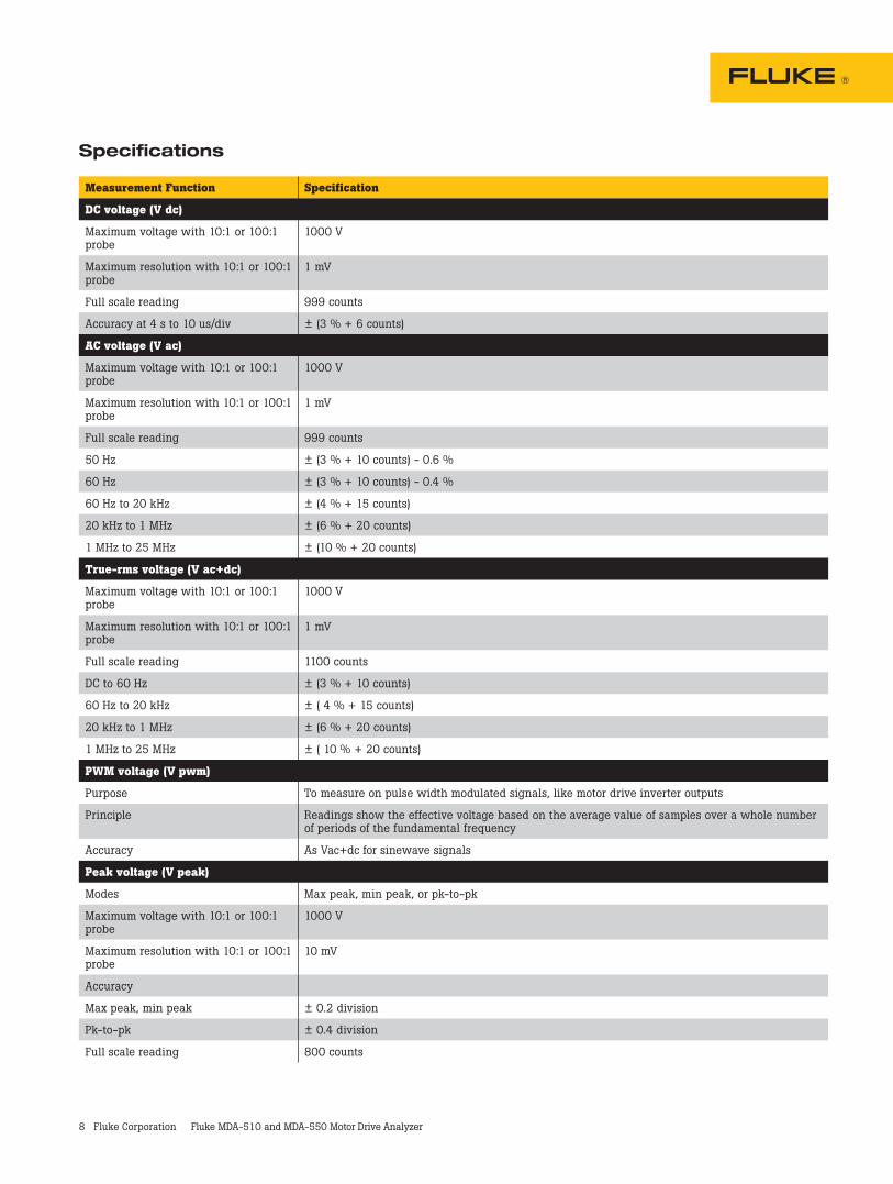
Specifications
Measurement Function Specification
DC voltage (V dc)
Maximum voltage with 10:1 or 100:1 probe
1000 V
Maximum resolution with 10:1 or 100:1 probe
1 mV
Full scale reading 999 counts
Accuracy at 4 s to 10 us/div ± (3 % + 6 counts)
AC voltage (V ac)
Maximum voltage with 10:1 or 100:1 probe
1000 V
Maximum resolution with 10:1 or 100:1 probe
1 mV
Full scale reading 999 counts
50 Hz ± (3 % + 10 counts) - 0.6 %
60 Hz ± (3 % + 10 counts) - 0.4 %
60 Hz to 20 kHz ± (4 % + 15 counts)
20 kHz to 1 MHz ± (6 % + 20 counts)
1 MHz to 25 MHz ± (10 % + 20 counts)
True-rms voltage (V ac+dc)
Maximum voltage with 10:1 or 100:1 probe
1000 V
Maximum resolution with 10:1 or 100:1 probe
1 mV
Full scale reading 1100 counts
DC to 60 Hz ± (3 % + 10 counts)
60 Hz to 20 kHz ± ( 4 % + 15 counts)
20 kHz to 1 MHz ± (6 % + 20 counts)
1 MHz to 25 MHz ± ( 10 % + 20 counts)
PWM voltage (V pwm)
Purpose To measure on pulse width modulated signals, like motor drive inverter outputs
Principle Readings show the effective voltage based on the average value of samples over a whole number of periods of the fundamental frequency
Accuracy As Vac+dc for sinewave signals
Peak voltage (V peak)
Modes Max peak, min peak, or pk-to-pk
Maximum voltage with 10:1 or 100:1 probe
1000 V
Maximum resolution with 10:1 or 100:1 probe
10 mV
Accuracy
Max peak, min peak ± 0.2 division
Pk-to-pk ± 0.4 division
Full scale reading 800 counts
9 Fluke Corporation Fluke MDA-510 and MDA-550 Motor Drive Analyzer
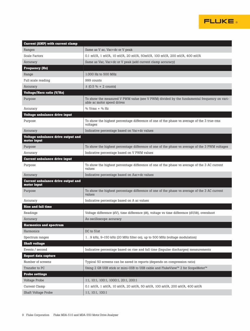
Current (AMP) with current clamp
Ranges Same as V ac, Vac+dc or V peak
Scale Factors 0.1 mV/A, 1 mV/A, 10 mV/A, 20 mV/A, 50mV/A, 100 mV/A, 200 mV/A, 400 mV/A
Accuracy Same as Vac, Vac+dc or V peak (add current clamp accuracy)
Frequency (Hz)
Range 1.000 Hz to 500 MHz
Full scale reading 999 counts
Accuracy ± (0.5 % + 2 counts)
Voltage/Herz ratio (V/Hz)
Purpose To show the measured V PWM value (see V PWM) divided by the fundamental frequency on vari-able ac motor speed drives
Accuracy % Vrms + % Hz
Voltage unbalance drive input
Purpose To show the highest percentage difference of one of the phase vs average of the 3 true-rms voltages
Accuracy Indicative percentage based on Vac+dc values
Voltage unbalance drive output and motor input
Purpose To show the highest percentage difference of one of the phase vs average of the 3 PWM voltages
Accuracy Indicative percentage based on V PWM values
Current unbalance drive input
Purpose To show the highest percentage difference of one of the phase vs average of the 3 AC current values
Accuracy Indicative percentage based on Aac+dc values
Current unbalance drive output and motor input
Purpose To show the highest percentage difference of one of the phase vs average of the 3 AC current values
Accuracy Indicative percentage based on A ac values
Rise and fall time
Readings Voltage difference (dV), time difference (dt), voltage vs time difference (dV/dt), overshoot
Accuracy As oscilloscope accuracy
Harmonics and spectrum
Harmonics DC to 51st
Spectrum ranges 1…9 kHz, 9-150 kHz (20 MHz filter on), up to 500 MHz (voltage modulation)
Shaft voltage
Events / second Indicative percentage based on rise and fall time (Impulse discharges) measurements
Report data capture
Number of screens Typical 50 screens can be saved in reports (depends on compression ratio)
Transfer to PC Using 2 GB USB stick or mini-USB to USB cable and FlukeView™ 2 for ScopeMeter™
Probe settings
Voltage Probe 1:1, 10:1, 100:1, 1000:1, 20:1, 200:1
Current Clamp 0.1 mV/A, 1 mV/A, 10 mV/A, 20 mV/A, 50 mV/A, 100 mV/A, 200 mV/A, 400 mV/A
Shaft Voltage Probe 1:1, 10:1, 100:1
10 Fluke Corporation Fluke MDA-510 and MDA-550 Motor Drive Analyzer
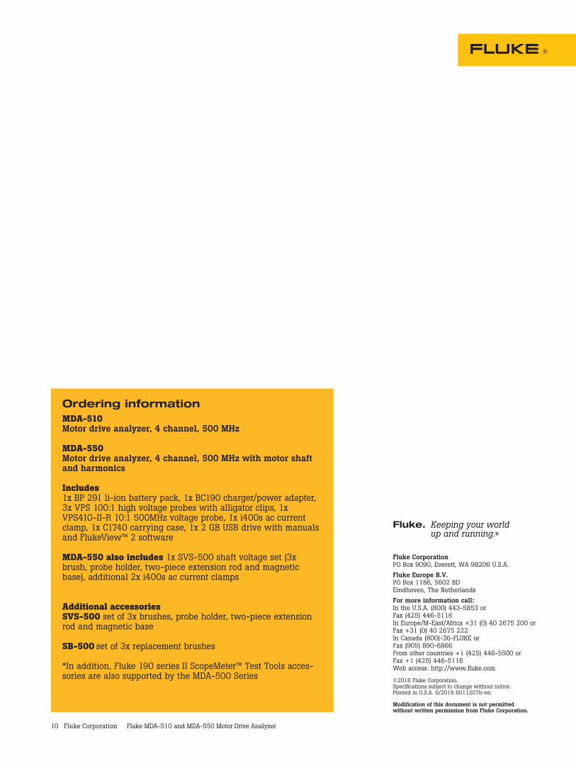
Ordering informationMDA-510 Motor drive analyzer, 4 channel, 500 MHz
MDA-550 Motor drive analyzer, 4 channel, 500 MHz with motor shaft and harmonics
Includes 1x BP 291 li-ion battery pack, 1x BC190 charger/power adapter, 3x VPS 100:1 high voltage probes with alligator clips, 1x VPS410-II-R 10:1 500MHz voltage probe, 1x i400s ac current clamp, 1x C1740 carrying case, 1x 2 GB USB drive with manuals and FlukeView™ 2 software
MDA-550 also includes 1x SVS-500 shaft voltage set (3x brush, probe holder, two-piece extension rod and magnetic base), additional 2x i400s ac current clamps
Additional accessoriesSVS-500 set of 3x brushes, probe holder, two-piece extension rod and magnetic base
SB-500 set of 3x replacement brushes *In addition, Fluke 190 series II ScopeMeter™ Test Tools acces-sories are also supported by the MDA-500 Series
Fluke Corporation PO Box 9090, Everett, WA 98206 U.S.A.Fluke Europe B.V. PO Box 1186, 5602 BD Eindhoven, The NetherlandsFor more information call: In the U.S.A. (800) 443-5853 or Fax (425) 446-5116 In Europe/M-East/Africa +31 (0) 40 2675 200 or Fax +31 (0) 40 2675 222 In Canada (800)-36-FLUKE or Fax (905) 890-6866 From other countries +1 (425) 446-5500 or Fax +1 (425) 446-5116 Web access: http://www.fluke.com
©2018 Fluke Corporation. Specifications subject to change without notice. Printed in U.S.A. 6/2018 6011207b-en
Modification of this document is not permitted without written permission from Fluke Corporation.
Fluke. Keeping your world up and running.®