Fluid-Structure Interaction Study on the Influence of ...jeffjournal.org/papers/Volume10/V10I1(19)...
12
Journal of Engineered Fibers and Fabrics 174 http://www.jeffjournal.org Volume 10, Issue 1 – 2015 Fluid-Structure Interaction Study on the Influence of Circular Gap of Parachute on Inflation Performance with Fixed Payload Lin Yang 1,2 , Lu Wang 3 , Li Yu 1 , Han Cheng 1 1 Nanjing University of Aeronautics and Astronautics, Nanjing CHINA 2 State Key Laboratory of Mechanics and Control of Mechanical Structures, Nanjing CHINA 3 Aviation Key Laboratory of Science and Technology on Aeronautical Life-Support, Xiangyang CHINA Correspondence to: Lin Yang email: [email protected] ABSTRACT In order to study the influence of circular gap controlled by the tearing force on rescue parachute inflation performance, the Arbitrary Lagrange-Euler (ALE) coupling method is utilized to simulate the inflation process of the circular gap rescue parachute with fixed payload; the contact failure model of the open of circular gap was built by the sewing force of the sewing thread. The canopy structure model influenced by fabric permeability performance is proposed, and the differential pressure of permeable fabric is described in Ergun equation through the textile material permeability test. The numerical results calculated by LS-DYNA are compared with the results of airdrop test and the empirical method of parachute-payloads dynamics, and it is shown that the steady drag coefficient and transient shape during inflation are more consistent with the airdrop test results, and the dimensionless initial inflation time and the maximum equivalent opening shock are more realistic. The stress variations of each gore unity during inflation are investigated. The most dangerous time-space state point during inflation process was discovered. With the study of the influence of the circular gap structure of parachute on inflation performance, the numerical results show the circular gap structure can reduce the opening load and adjust the time of two inflation stages, which reduces the maximum effective stress in dangerous parts and improves the safety of canopy. Keywords: parachute; circular gap; inflation process; opening load; fluid-structure interaction INTRODUCTION Maximizing the work scope of a rescue parachute is a serious challenge for all designers: on the one hand the rescue parachute should provide rapid opening and inflation at low altitude and low speed to ensure enough open height and terminate descent time, on the other hand the rescue parachute should provide slow inflation and small open shock at high altitude and high speed to ensure the safety of pilot. To solve the above conflicts, the most effective method is to utilize an adjustable ventilation structure. A number of experiments show that multi-gap adaptive gore structure can decrease open load through increasing ventilation at high speed [1]. Because of the improvement of the work scope of a rescue parachute, current adaptive gore design could not meet the requirement of higher opening velocity. The circular gap structure of a rescue parachute, which can be torn by opening force influenced by velocity, becomes an important measure to reduce the opening load at high speed and to quickly up the inflation at low speed. In order to effectively assess the influence of circular gap structure on inflation process and realize the goal of the optimization design of circular gap, the inflation process of this structure parachute is investigated by fluid-structure interaction (FSI) method. The inflation process of a parachute is an intensive FSI process. Very recently, however, we have seen successful FSI modeling of parachute inflation from one stage to mutistage (disreefing), including the new modified geometric porosity design of the main parachute [2-3]. Due to the complexity and limitations of computational resource, the inflation
Transcript of Fluid-Structure Interaction Study on the Influence of ...jeffjournal.org/papers/Volume10/V10I1(19)...

Journal of Engineered Fibers and Fabrics 174 http://www.jeffjournal.org Volume 10, Issue 1 – 2015
Fluid-Structure Interaction Study on the Influence of Circular Gap of Parachute on Inflation Performance with
Fixed Payload
Lin Yang 1,2, Lu Wang3, Li Yu 1, Han Cheng 1
1Nanjing University of Aeronautics and Astronautics, Nanjing CHINA
2State Key Laboratory of Mechanics and Control of Mechanical Structures, Nanjing CHINA
3Aviation Key Laboratory of Science and Technology on Aeronautical Life-Support, Xiangyang CHINA
Correspondence to: Lin Yang email: [email protected]
ABSTRACT In order to study the influence of circular gap controlled by the tearing force on rescue parachute inflation performance, the Arbitrary Lagrange-Euler (ALE) coupling method is utilized to simulate the inflation process of the circular gap rescue parachute with fixed payload; the contact failure model of the open of circular gap was built by the sewing force of the sewing thread. The canopy structure model influenced by fabric permeability performance is proposed, and the differential pressure of permeable fabric is described in Ergun equation through the textile material permeability test. The numerical results calculated by LS-DYNA are compared with the results of airdrop test and the empirical method of parachute-payloads dynamics, and it is shown that the steady drag coefficient and transient shape during inflation are more consistent with the airdrop test results, and the dimensionless initial inflation time and the maximum equivalent opening shock are more realistic. The stress variations of each gore unity during inflation are investigated. The most dangerous time-space state point during inflation process was discovered. With the study of the influence of the circular gap structure of parachute on inflation performance, the numerical results show the circular gap structure can reduce the opening load and adjust the time of two inflation stages, which reduces the maximum effective stress in dangerous parts and improves the safety of canopy. Keywords: parachute; circular gap; inflation process; opening load; fluid-structure interaction
INTRODUCTION Maximizing the work scope of a rescue parachute is a serious challenge for all designers: on the one hand the rescue parachute should provide rapid opening and inflation at low altitude and low speed to ensure enough open height and terminate descent time, on the other hand the rescue parachute should provide slow inflation and small open shock at high altitude and high speed to ensure the safety of pilot. To solve the above conflicts, the most effective method is to utilize an adjustable ventilation structure. A number of experiments show that multi-gap adaptive gore structure can decrease open load through increasing ventilation at high speed [1]. Because of the improvement of the work scope of a rescue parachute, current adaptive gore design could not meet the requirement of higher opening velocity. The circular gap structure of a rescue parachute, which can be torn by opening force influenced by velocity, becomes an important measure to reduce the opening load at high speed and to quickly up the inflation at low speed. In order to effectively assess the influence of circular gap structure on inflation process and realize the goal of the optimization design of circular gap, the inflation process of this structure parachute is investigated by fluid-structure interaction (FSI) method. The inflation process of a parachute is an intensive FSI process. Very recently, however, we have seen successful FSI modeling of parachute inflation from one stage to mutistage (disreefing), including the new modified geometric porosity design of the main parachute [2-3]. Due to the complexity and limitations of computational resource, the inflation

Journal of Engineered Fibers and Fabrics 175 http://www.jeffjournal.org Volume 10, Issue 1 – 2015
process of a parachute is usually studied utilizing semi-theoretical methods [1,4] which some parachute parameters, such as the drag characteristics, and additional mass factors, need to rely on empirical formulas or data. The parachute–payload system is divided into several objects described by particle or rigid body in these methods. And the trajectory, load, and other parameters of research objects are obtained, but the canopy shape and stress, the flow field surrounding the parachute, and other dynamic characteristic cannot be obtained. The FSI mechanical mechanism of the parachute inflation process cannot be revealed. The FSI problem of parachute inflation process is highly unsteady and nonlinear, which is very difficult and complex. The solution involves large grid deformation, a key problem of numerical calculation of the contact of coupling interface, and huge computational consumption in space-time discrete calculation. The computational fluid dynamics/mass spring damper (CFD/ MSD) model is used in the earlier FSI method based on time-space dispersing. In this model, the parachute is dispersed into a series of mass points connected by the springs and dampers. And their movement is controlled by flow field force, spring force and damping force. The two-dimensional parachute inflation process was simulated utilizing this method in literature [5-7]. At present, one of the most commonly used methods in 3D parachute FSI modeling is the deforming – spatial - domain/stabilized space-time (DSD/SST) method [8-9]. Based on the DSD/SST method, which was used for 3D computations [10-11] soon after its development, FSI modeling of several kinds of parachutes were carried out, including ram-air parachutes [12], solid round parachutes [13], solid cross parachutes [14], and complex solid parachute designs [15]. With the new generation DSD/SST formulations and space-time FSI techniques [16], many additional 3D computational challenges involved in parachute FSI were addressed, including the ringsail parachutes [17,-18], reefed ringsail parachutes [19], Orion spacecraft parachutes [20], spacecraft parachute clusters [21-22], inflation of spacecraft parachutes from reefed stages [2, 3, 23], spacecraft parachutes with modified geometric porosity [24], parachutes for spacecraft cover separation [25], and clusters of
spacecraft parachutes with modified geometric porosity [26]. In 2005, Tutt and Taylor made good progress for 3D FSI problem of parachute utilizing LS-DYNA [27-28]. The same method is also used in simulating the inflation process of flat circular parachute and bottom-stretching parachute in [29-30]. In recent FSI modeling of inflation (disreefing) of spacecraft parachutes reported in [2-3], the canopy shapes change dramatically as the parachutes disreef from one stage to another, the shapes of the geometric porosities change also dramatically, the fabric porosity is taken into account, and the fabric stresses during the inflation process are computed and reported. In this paper, a new contact failure equation is presented to simulate the open of the circular gap, and the canopy stress model influenced by fabric permeability described in Ergun equation is built. Some parameters of Ergun equation is obtained through the textile material permeability test. The FSIs of inflation processes of asymmetric parachute with and without circular gap are simulated using the transient dynamic finite element code LS-DYNA, and the canopy transient stress distribution is obtained. The numerical results are compared with air drop tests to verify the validity of this method. On this basis, the differences of inflation shape, inflation time, open load and stress distribution on canopy surface of parachutes with and without circular gap are compared. The results confirm that circular gap design has good effect of inflation adjustment and reduce the opening load which greatly improves the safety performance of canopy. MATHEMATICAL MODEL Governing Equations In the inflation process of flexible canopy, the flow field grids near structure will have large deformation. In order to avoid severe deformation, the Arbitrary Lagrangian Eulerian (ALE) method is utilized in calculation of parachute inflation process [31-32]. Flow field governing equations are:
F FF
F F F , F F
0
( 1,2,3)
ii
i i
i ii ij j i
j
v wt x x
v vw b jt x
∂∂ ∂ + + = ∂ ∂ ∂ ∂ ∂ + = + = ∂ ∂
ρ ρρ
ρ ρ σ ρ
(1)

Journal of Engineered Fibers and Fabrics 176 http://www.jeffjournal.org Volume 10, Issue 1 – 2015
Structure (coupling surface) governing equation is:
2S,
S S , S S2
dd
iij j i
ub
t= +ρ σ ρ (2)
In the above equation, the subscripts F, S represent fluid domain and structure domain. ρ is the
density. iv and iw represent flow velocities relative
to spatial domain and reference domain,
respectively. S,iu represents the displacement of
coupling structure surface. ijσ is the stress. ib
represents volume force. In this paper the space discretization is based on updated Lagrangian format, the mesh tracks material domain boundary, the mass is automatic in conservation, and the inertia force in control surface is 0 (the influence of convective term is negligible). In this way, the governing equations of flow field and structure (1), (2) can be simplified into the following format:
int ext ( 1, 2,3)A Aj Aj AjM u F F j+ = = (3)
From the left to right in Eq. (3), the three terms represent inertia force, internal force and external force. A is node number, j is the coordinate direction. Eq. (3) is discrete by finite element method, the central difference explicit dynamics numerical algorithm is utilized to obtain the material node displacement of next moment, and then find the node coordinates, element stress, strain and other state parameters. To ensure the stability of convergence, the time step is given by the following equation:
min( / )ct t L cα∆ < ∆ = (4)
In the above equation,
minL is the minimum element
edge length, c is the sound velocity of the material, α is the scaling factor (0.7 in this paper).
Fabric Permeability Model For the thin membrane two-dimensional canopy fabric, the stress can be expressed as:
( )S n p nσ τ σ⋅ = + − + ⋅ (5)
In the above equation, τ is the force except aerodynamic force, ,p σ are flow field pressure and frictional force, respectively. The fabric flow field pressure combined with performance data of fabric permeability can be calculated by penalty function method.
F
S
Fn
Sn
FvSv
n
FIGURE 1. The permeable model of computational domain.
The adjacent primary and secondary nodes F S,n n
are separately defined in flow field domain (F) and structure domain(S). n is the exterior normal direction of two-dimensional fabric surface element (Figure 1). In the moment of i, the penetration
displacement pid
between primary and secondary
nodes is described by the following equation:
t i= ,121
p p rel Δii i t−−= + ⋅d d v
(where1 1 12 2 2
rel S F
i i in n
− − −= −v v v ) (6)
When p 0i⋅ <n d , the pressure of internal and
external flow field (coupling force) is obtained by numerical calculation from Ergun equation of fabric permeability:
Journal of Engineered Fibers and Fabrics 177 http://www.jeffjournal.org Volume 10, Issue 1 – 2015
2rel rel[ ( ) ]p a b e= ⋅ ⋅ + ⋅ ⋅ ⋅v n v n (7)
Where, a, b represent viscosity coefficient and inertia coefficient respectively, which describe the fabric permeability, e is the canopy thickness. These parameters of Eq. (7) are obtained by the textile material permeability test. Variable Slotted Structure Model The open loads and inflation times vary considerably at different altitudes and speeds; the design requirement of parachute is difficult to satisfy different working conditions simultaneously. To improve the work scope of rescue parachute, the canopy with tear belt is designed, as shown in Figure 2. The tear belt between i ring and i+1 ring will be torn under the high speed and large open load, the canopy circular gap will appeared, then the structure permeability will increase and the open load will decrease.
i+1 ring
i ring
Constrained point 1
Constrained point 2
Sewing thread
Constrained point 1Constrained point 2
FIGURE 2. Canopy with tear belt.
The open of ventilation structure was free of restraint. And the structure contact failure equation for opening tear belt is built based on the working principle. The structure constrained point is set on the joint of tear belt, i ring and i+1 ring of the canopy. When the load applied on the structure constrained point is large than the sewing force of the sewing thread, the circular gap will open, and the failure equation can be expressed as:
2 2
1n s
n s
f fS S
+ ≥
(8)
In the equation,
,n sf f are the normal force and
tangential force. ,n sS S are the normal force and
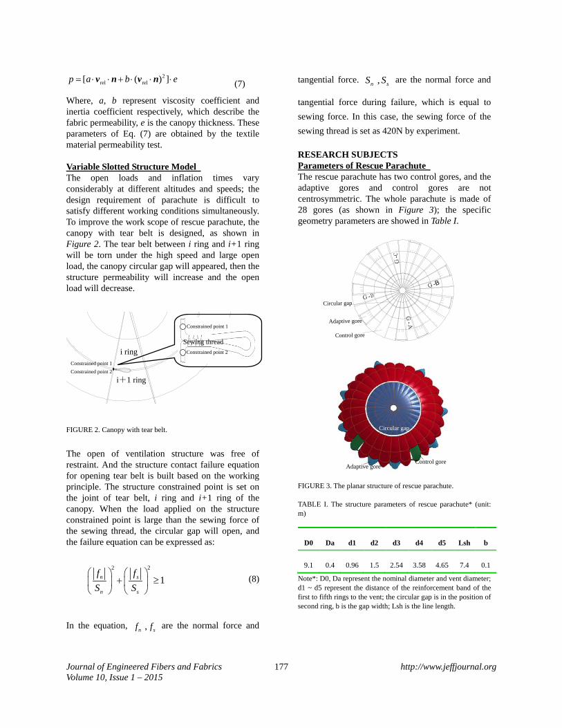
tangential force during failure, which is equal to sewing force. In this case, the sewing force of the sewing thread is set as 420N by experiment. RESEARCH SUBJECTS Parameters of Rescue Parachute The rescue parachute has two control gores, and the adaptive gores and control gores are not centrosymmetric. The whole parachute is made of 28 gores (as shown in Figure 3); the specific geometry parameters are showed in Table I.
Adaptive gore
Control gore
Circular gap
G-A
G-C
G-B
G-D
Adaptive goreControl gore
Circular gap
FIGURE 3. The planar structure of rescue parachute. TABLE I. The structure parameters of rescue parachute* (unit: m)
D0 Da d1 d2 d3 d4 d5 Lsh b
9.1 0.4 0.96 1.5 2.54 3.58 4.65 7.4 0.1
Note*: D0, Da represent the nominal diameter and vent diameter; d1 ~ d5 represent the distance of the reinforcement band of the first to fifth rings to the vent; the circular gap is in the position of second ring, b is the gap width; Lsh is the line length.

Journal of Engineered Fibers and Fabrics 178 http://www.jeffjournal.org Volume 10, Issue 1 – 2015
In order to accommodate larger open load, the upper and lower part of circular gap of this rescue parachute are made of elastic silk and brocade silk material respectively, and the elasticity modulus of which are 2.9e9 Pa and 4.62e8 Pa respectively. Fabric permeability is fitted as Ergun equation
through test [16-17]: 2( )q qP av bv e∆ = +
Where pv is the flow velocity through the canopy
fabric, △P is differential pressure from the canopy fabric test. Through air permeability test, the viscosity coefficient a and inertia coefficient b of these two fabrics can be obtained: Upper canopy:
5 3 4 45.99 10 / , 6.36 10 /a kg m s b kg m= × ⋅ = × ;
Lower canopy: 5 3 5 42.19 10 / , 2.5 10 /a kg m s b kg m= × ⋅ = × .
Numerical Model The parachute inflation is greatly influenced by many parameters such as weight and dimension of payload, the structure and dimension of parachute, flying attitude and speed, end etc. The influence by payload and flight status should be neglected in order to better assess the influence of circular gap structure on rescue parachute inflation performance. The test working condition in wind tunnel is used as calculation working condition, in which the influence of payload and flight status doesn’t exist. With the condition of the same parachute type and ring width, the FSI numerical calculation of inflation process of parachutes with (the nominal area is 65.2 m2) and without (the nominal area is 64.5 m2) circular gap are carried out. In this calculation, the inflation speed is set as 40m/s, the air density is set as 1.0kg/m3, the sewing force of circular gap is set as 420N. The parachute initial shape is in the straight state, the canopy is established as 3 nodes thin-membrane element, and the line and reinforcement band are set as rod elements, as shown in Figure 4. The flow field is hexahedral element, the computational domain along axial, normal, lateral direction of parachute are 6D0×3D0×3D0 (D0 is the canopy nominal diameter, where the wake length is about
4D0). The parachute canopy mesh of two structures are exactly the same, 32,156 triangle elements are established. For each reinforcement band of circular gap of parachute, 4 elements increase. And the whole canopy increases 122 rod elements. The rod elements are respectively 3900 and 3788. The flow field grid number is about 690,000. The time step size is only 6.7e-6 second and the termination time is set as 2 seconds, while, the number of iterations of solving structure and fluid equations is 1 and 50 respectively. The coupling calculation is performed on the DELL T5500 workstation of 12-core, 32G-memory, the time step is set as two seconds, the consumed calculation time are respectively 198,030 seconds and 192,548 seconds.
FIGURE 4. (color online) surface mesh of the rescue parachute canopy.
The initial conditions of the calculation are
0 0, ;F in Fv v p const= = 0 00, 0S Sv σ= = . ( In this case,
inv is equal to 40m/s) The boundary conditions of flow field: inlet, in=v v ;
outlet, 0 0pn n∂ ∂
= =∂ ∂v ; wall, 0
n∂
=∂v .
The boundary conditions of coupling surface:
s=v v ( sv is the movement speed of coupling
surface). The boundary conditions of intersection point of
lines: , 0S Nu = .
NUMERICAL SIMULATION ANALYSIS Analysis Method The nominal area of rescue parachute used in this paper is almost 65 m2, which can’t be tested in wind tunnel. Because the permeability and structural mechanics of scale model cannot be similar with

Journal of Engineered Fibers and Fabrics 179 http://www.jeffjournal.org Volume 10, Issue 1 – 2015
that of actual parachute, the great difference of the open performances and aerodynamic performances between the scale model and actual parachute are exist. The data measured is very limited and the trajectory and speed also will change in airdrop test, which is not agreed with the calculation conditions. The test results cannot be directly utilized to verify the calculation results. Therefore, the numerical results are analyzed to verify the reasonableness according to parachute theory. According to the parachute theory, it is the case of infinite mass inflation when the speed barely changes in the inflation process; other cases are finite mass inflation cases. In this calculation condition, it is infinite mass case. However, in the cases of parachute-load dynamics and airdrop test, it is finite mass case, so direct comparison between these two cases is difficult. But the maximum open load for these two cases can be calculated as follows: Infinite mass:
inf 2max
1 ( )2k dF v CA Kρ= (8)
Finite mass:
fin 2max
1 ( ) ( 1)2k L d j jF v CA K K Kρ= ≤ (9)
In above equations, ,L d jv K K, are straighten speed,
dynamic load factor and finite mass correction coefficient, respectively. Kd is mainly influenced by parachute types, the values of which in the two cases are equal. Kj is influenced by load per unit area of parachute, and usually it is set as 0.03 for the ordinary parachute used by people [2].
The parachute-payload system will achieve equilibrium eventually in the case of airdrop test. The aerodynamic coefficients in the case of finite mass will agree with that in the case of infinite mass. The reasonability of the numerical results is analyzed through the comparison of open load and steady aerodynamic coefficients by FSI method, classical parachute-payload dynamics method [2] and airdrop test method. Numerical Results Analysis Taking a parachute with circular gap as research object, the calculation state of parachute-payload dynamics is consistent with airdrop test state, and the open speed is 650km/h, open height is 4000m and payload mass is 100kg. In the airdrop test, high-speed cameras, force sensors and speed sensors are utilized to measure the shape, load and speed. Fourth-order Rugge-Kutta method is utilized to obtain the performance curve (Figure 5) of opening stage of parachute-payload system. The initial inflation speeds obtained in these two cases are 161m/s and 160m/s, respectively. The main parameters in opening stage of parachute are shown in Table II.
0.0 0.2 0.4 0.6 0.8 1.0 1.2 1.4
20
40
60
80
100
120
140
160
180
t/s
v/m·
s-1
velocity-deployment phase velocity-inflation phase load-deployment phase load-inflation phase
0
5000
10000
15000
20000
25000
30000
35000
F/N
FIGURE 5. The velocity curve of parachute opening.

Journal of Engineered Fibers and Fabrics 180 http://www.jeffjournal.org Volume 10, Issue 1 – 2015
TABLE II. Main parameters in parachute opening stage.
Note1: rigid reverse pull model [2] is utilized in deployment stage in classical method, inflation distance method [2] is utilized in inflation stage (initial inflation distance coefficient is set as 1.7, full inflation distance coefficient is set as 8.0), aerodynamic coefficient as input is set as 0.9. Note2: inflation time from test is obtained through high-speed camera imaging method. Drag coefficient is input in classical method, which needs to rely on experience, and the accuracy of calculation depends on the accuracy of aerodynamic coefficient. The aerodynamic performance is calculated by interaction of structure and flow field in coupling analysis method, which reflects the actual mechanical mechanism. The steady drag coefficients from coupling calculation are exactly close to test results, as shown in Table II. The difference of opening shock is very great compared with the result between FSI method and airdrop test method, because there are different working conditions. According to Eq. (7) and Eq. (8), the opening shock ratio of the two working condition is 2.604, and the equivalent opening shock is 19.3 KN in airdrop condition by FSI method. The error of FSI method compared with airdrop test method is only 13.8%. However, the error of classical parachute-load dynamics method compared with airdrop test method is 18.9%. This shows that the coupling numerical results are more accurate.
Full inflation times obtained from FSI method and classical method are both shorter than actual full inflation time of airdrop test. The main reasons are as follows: the parachute is light and large, in actual working condition the parachute inflation is greatly influenced by meteorological wind, environmental disturbance and other complex external factors which will deteriorate the inflation condition and prolong inflation time. Due to the simplification of parachute as a particle in classical parachute-payload dynamics model, the transient shape cannot be obtained, and dimensionless initial inflation time (the ratio of initial inflation time and full inflation time) is pretty different with actual situation. The influence of dimension and material parameters are fully considered in FSI method and the time allocation of two stages in inflation process is more consistent with actual situation.

Journal of Engineered Fibers and Fabrics 181 http://www.jeffjournal.org Volume 10, Issue 1 – 2015
THE INFLUENCE OF CIRCULAR GAP ON INFLATION PERFORMANCE The Transient Canopy Shape
FIGURE 6. Transient canopy shape during inflation. The computational results were obtained with fixed payload and at inflow speed of 40 m/s. The top, test figure; the middle, with circular gap; the bottom, without circular gap.
0.0 0.2 0.4 0.6 0.8 1.0 1.2 1.4
0
1
2
3
4
5
6
7
t/s
Dinlet/m
without circular gap with circular gap
FIGURE 7. The projection diameter of inlet.
0.0 0.2 0.4 0.6 0.8 1.0
0.0
0.1
0.2
0.3
0.4
Dapex/m
t/s
without circular gap with circular gap
FIGURE 8. The projection diameter of vent.
TABLE III. Characteristic parameter of inflation process.
Initial
inflation time (/s)
Full inflation time (/s)
Dimensionless initial
inflation time
Steady inlet
diameter (/m)
With circular
gap 0.435 0.82 0.53 5.95
Without circular
gap 0.324 0.783 0.41 5.93
The FSI numerical calculations are carried out for the structures with and without circular gap, respectively. Figure 6 is the shape comparison of two calculation conditions with airdrop test under dimensionless inflation time (the ratio of inflation time and full inflation time), the projection diameter curves of canopy inlet and vent (Figure 7~ Figure 8) are obtained through numerical calculation, and the main character parameters are shown in Table III. The results show that: (1) The change of canopy shape experience three
stages: first, the canopy skirt opens first and the inlet area increase. Second, the canopy will inflate from apex to skirt while the column

Journal of Engineered Fibers and Fabrics 182 http://www.jeffjournal.org Volume 10, Issue 1 – 2015
shape is formed, the canopy skirt will shrink and the inlet area will decrease. At last, the internal pressure distribution becomes more average, the inlet area increase until the canopy is completely full.
(2) The canopy shape change regular with circular gap structure is not obvious. The internal pressure gradient in the canopy with circular gap is smaller because of the larger structure permeability, and the shrink of lower canopy is not obvious, as shown in Figure 7.
(3) The canopy shape of these two structures is very close, as shown in Figure 6 and Figure 7. The inlet equivalent diameters of full inflation are almost equal, and the nominal diameter ratios are 0.653 and 0.654, respectively, the difference is only 0.15%.
(4) Breathe phenomenon of opening and shrinkage also emerges in vent, but appears in the initial inflation stage, while breathe phenomenon in canopy skirt usually after the canopy is full is not obvious in this examples of both structures.
(5) The inflation time and dimensionless initial inflation time of the structure with circular gap are longer, it indicates that the circular gap not only extend inflation time but also extend the initial inflation time which is just the phase with high speed and large load. The prolonged inflation time can bring the good offload effect.
The Opening Load
FIGURE 9. The opening load during inflation. Figure 9 is the curve of opening load of parachute of two structures in inflation process. In infinite mass case, the opening shocks of two structures are 50.2KN and 52.04KN, respectively, which appear in full inflation stage. While in initial inflation stage,
load fluctuation emerges because of breathe phenomenon and oscillation of the upper canopy. The steady drag coefficients of two structures are 0.92 and 0.95. This result shows that the circular gap has certain offloading effect, while the steady drag coefficient slightly reduces.
The Stress Distribution of Canopy
1 2 3 4 5 6 7 8 9 10 11 12 13 14
FIGURE 10. Research elements of canopy gore. Because the number of canopy elements is more than 30,000, in order to more effectively analyze the stress change and distribution in canopy surface, four symmetrical gores are selected (Figure 3, GA~GD). 14 elements are researched in each gore, and they are located in 120mm distance to the adjacent latitudinal reinforcement lines and the center of trapezoidal blocks, as shown in Figure 10. The transient stress distribution along gore radial direction is analyzed by the average value of four gores.
FIGURE 11. Transient stress of different elements with circular gap.

Journal of Engineered Fibers and Fabrics 183 http://www.jeffjournal.org Volume 10, Issue 1 – 2015
FIGURE 12. Transient stress of different elements without circular gap.
Figure 11 and 12 are the transient stress distribution of 14 elements in the radial direction of the canopy with and without circular gap. The maximum stress and the average stress in a relatively stable state of these elements (1~ 14) are obtained, as shown in Figure 13 and 14. The following conclusions can be obtained according to the numerical results. 1) Stress pulsation is very intense in each element. The maximum stress of upper canopy appears in initial inflation stage, while appears in full inflation stage nearby canopy skirt. 2) When the vent nearly open, canopy stress peak is large and focus on element 2 to 4, which are the most dangerous time-space state point during inflation process. The general safety performance of the parachute can be improved just to improve strength of these parts of canopy. 3) Circular gap has large influence on the maximum effective stress, the maximum effective stress in upper gores all decrease, especially near the circular gap (Element 5~ Element 7). The maximum effective stress of Element 6 is reduced by 38%, which will greatly improve the overall safety performance of parachute. 4) After full inflation, the average effective stress in upper part of circular gap decrease along the radial direction, while it shows ‘V’ trend in lower part of circular gap along the radial direction. The maximum effective stress appears in the middle part (Element 10~ Element 12) in full inflation process, as shown in Figure 14. 5) Circular gap has little influence on effective stress in a stable state. When the air flow through circular gap, the stress in upper canopy will reduces, but it is not affected to canopy skirt.
CONCLUSION In this paper, the FSI coupling calculation of a rescue parachute with variable slotted structure is presented. The numerical result is compared with that of test method and classical parachute-payload dynamics method. It shows that the FSI method has some advantages, such as high accuracy, large amount of information, and does not need to know aerodynamic properties of parachute in advance.. Some conclusions are as follows: 1) Although circular gap has little influence on canopy shape in a stable state, it could prolong inflation time, especially the initial inflation time, which has obvious effect to control and adjustment the inflation time. 2) Circular gap has good offloading effect, but it would slightly decrease the steady drag coefficient. 3) In inflation process, stress pulsation is very intense in each element. When the vent nearly open, the load in upper canopy is large, and that part is most prone to damage. The general safety performance of the parachute can be improved just to improve strength of these parts of canopy. 4) Circular gap could greatly reduce the maximum effective stress near circular gap and greatly improve the safety performance of the parachute. But the influence on average effective stress in a stable state is not significant. ACKNOWLEDGMENT This project was supported by the National Natural Science Foundation of China (Grant No. 11172137) and the Fund of Aeronautics Science (Grant No. 20122910001) REFERENCES [1] Wang L R 1997 Parachute Theory and
Application (Beijing: Astronautics Publishing House) 1997:187-229. (in Chinese)
[2] K. Takizawa, M. Fritze, D. Montes, T. Spielman and T.E. Tezduyar, "Fluid-Structure Interaction Modeling of Ringsail Parachutes with Disreefing and Modified Geometric Porosity", Computational Mechanics, 50 (2012) 835-854.
[3] K. Takizawa, T.E. Tezduyar, C. Boswell, R. Kolesar and K. Montel, "FSI Modeling of the Reefed Stages and Disreefing of the Orion Spacecraft Parachutes", Computational Mechanics, published online DOI: 10.1007/s00466-014-1052-y (2014).

Journal of Engineered Fibers and Fabrics 184 http://www.jeffjournal.org Volume 10, Issue 1 – 2015
[4] Peng Y, Cheng W K, Song X M, et al. Summary for the Research Methods of Parachute Inflation Process [J]. Chinese Space Science and Technology, 2004, (3): 38-44. (in Chinese)
[5] Stein K R, Benney R J and Steeves E C 1993 A computational model that couples aerodynamic structural dynamic behavior of parachutes during the opening process (Natick: United States Army Natick Research, Development And Engineering Center) [R] NASA-ADA264115,1993p.5
[6] Yu L and Ming X 2007 Study on transient aerodynamic characteristics of parachute opening process [J]. Acta Mechanica Sinica,2007, 23(6): 627-633.
[7] Yu L, Shi X L and Ming X 2007 Numerical Simulation of Parachute During Opening Process[J].Acta Aeronautica et Astronautica Sinica, 2007,28(1):52-57.(in Chinese)
[8] Tezduyar TE, Behr M, Mittal S. A new strategy for finite element computations involving moving boundaries and interfaces-the deforming-spatial-domain/space–time procedure: I. The concept and the preliminary numerical tests. Comput Methods Appl Mech Eng 1992; 94(3):339–351.
[9] Tezduyar TE, Behr M, Mittal S, Liou J. A new strategy for finite element computations involving moving boundaries and interfaces-the deforming-spatial-domain/space–time procedure: II. Computation of free-surface flows, two-liquid flows, and flows with drifting cylinders. Comput Methods Appl Mech Eng 1992; 94(3):353–371.
[10] Tezduyar TE, Aliabadi S, Behr M, Johnson A and Mittal S, "Parallel Finite Element Computation of 3D Flows", Computer, 26 (1993) 27-36.
[11] Tezduyar TE, Aliabadi SK, Behr M and Mittal S, "Massively Parallel Finite Element Simulation of Compressible and Incompressible Flows", Computer Methods in Applied Mechanics and Engineering, 119 (1994) 157-177.
[12] Kalro V and Tezduyar TE 2000 A parallel 3D computational method for fluid–structure interactions in parachute systems [J]. Comput Methods Appl Mech Eng, 2000, 190:321–332.
[13] Stein K, Benney R, Kalro V, et al. Parallel computation of parachute fluid-structure interactions[R]. Proceedings of the 14th AIAA Aerodynamic Decelerator Technology Conference, San Francisco, AIAA-97-1505, 1997. p.277
[14] Stein K, Benney R, Tezduyar TE, Potvin J. Fluid–structure interaction of a cross parachute: numerical simulation. Comput Methods Appl Mech Eng 2001; 191(6–7):673–87.
[15] Sathe S, Benney R, Charles R, Doucette E, Miletti J, Senga M, Stein K and Tezduyar TE, "Fluid-Structure Interaction Modeling of Complex Parachute Designs with the Space-Time Finite Element Techniques", Computers & Fluids, 36 (2007) 127-135.
[16] Tezduyar TE and Sathe S, "Modeling of Fluid-Structure Interactions with the Space-Time Finite Elements: Solution Techniques", International Journal for Numerical Methods in Fluids, 54 (2007) 855-900.
[17] Tezduyar TE, Sathe S, Pausewang J, Schwaab M, Christopher J and Crabtree J, "Interface Projection Techniques for Fluid-Structure Interaction Modeling with Moving-Mesh Methods", Computational Mechanics, 43 (2008) 39-49.
[18] Tezduyar TE, Sathe S, Pausewang J, Schwaab M, Christopher J, Crabtree J. Fluid–structure interaction modeling of ringsail parachutes. Comput Mech 2008; 43(1):133–142.
[19] Tezduyar TE, Takizawa K, Moorman C, Wright S and Christopher J, "Space-Time Finite Element Computation of Complex Fluid-Structure Interactions", International Journal for Numerical Methods in Fluids, 64 (2010) 1201-1218.
[20] Takizawa K, Moorman C, Wright S, Spielman T and Tezduyar TE, "Fluid-Structure Interaction Modeling and Performance Analysis of the Orion Spacecraft Parachutes", International Journal for Numerical Methods in Fluids, 65 (2011) 271-285.
[21] Takizawa K, Wright S, Moorman C and Tezduyar TE, "Fluid-Structure Interaction Modeling of Parachute Clusters", International Journal for Numerical Methods in Fluids, 65 (2011) 286-307.

Journal of Engineered Fibers and Fabrics 185 http://www.jeffjournal.org Volume 10, Issue 1 – 2015
[22] Takizawa K, Spielman T and Tezduyar TE, "Space-Time FSI Modeling and Dynamical Analysis of Spacecraft Parachutes and Parachute Clusters", Computational Mechanics, 48 (2011) 345-364.
[23] Takizawa K, Bazilevs Y, Tezduyar TE, Hsu M.-C, Oiseth O, Mathisen KM, Kostov N and McIntyre S, "Engineering Analysis and Design with ALE-VMS and Space-Time Methods", Archives of Computational Methods in Engineering, published online, DOI: 10.1007/s11831-014-9113-0 (2014).
[24] Takizawa K and Tezduyar TE, "Computational Methods for Parachute Fluid-Structure Interactions", Archives of Computational Methods in Engineering, 19 (2012) 125-169.
[25] Takizawa K, Montes D, Fritze M, McIntyre S, Boben J and Tezduyar TE, "Methods for FSI Modeling of Spacecraft Parachute Dynamics and Cover Separation", Mathematical Models and Methods in Applied Sciences, 23 (2013) 307-338.
[26] Takizawa K, Tezduyar TE, Boben J, Kostov N, Boswell C and Buscher A, "Fluid-Structure Interaction Modeling of Clusters of Spacecraft Parachutes with Modified Geometric Porosity", Computational Mechanics, 52 (2013) 1351-1364.
[27] Benjamin A. Tutt, Anthony P. Taylor. The use of LS-DYNA to Simulate the Inflation of a Parachute Canopy[C].18th AIAA Aerodynamic Decelerator Systems Technology Conference and Seminar. AIAA-2005-1608.
[28] Benjamin A. Tutt, Anthony P. Taylor. The Use of LS-DYNA to Assess the Performance of Airborne Systems North America Candidate ATPS Main Parachutes[C].18th AIAA Aerodynamic Decelerator Systems Technology Conference and Seminar. AIAA-2005-1609.
[29] Yves Coquet, Pascal Bordenave. Improvements in Fluid Structure Interaction Simulation of Parachute using LS-Dyna[C]. 21st AIAA Aerodynamic Decelerator Systems Technology Conference and Seminar. AIAA-2011-2590.
[30] Cheng H, Yu L and Xia G 2013 A study on“bottleneck”phenomenon during parachute inflation [J]. JOURNAL OF NATIONAL UNIVERSITY OF DEFENSE TECHNOLOGY. 35(1) 48-52.(in Chinese).
[31] YU L,Cheng H, Zhan Y N, Li S T. Study of parachute inflation process using fluid–structure interaction method [J]. Chinese Journal of Aeronautics, (2014), 27(2):272-279.
[32] Cheng H, Zhang X H, Yu L, Chen M. Study of velocity effects on parachute inflation performance based on fluid-structure interaction method [J]. Applied Mathematics and mechanics, (2014). 35(9) :1177-1188
[33] Jia H, Rong W and Chen G L 2009 Spacecr. Recovery Remote Sens.30 15(in Chinese).
[34] Cheng H, Yu L, Rong W, etc. A Numerical Study of Parachute inflation Bases on a Mixed Method [J]. Aviation, 2012, 16(4):115–123.
AUTHORS’ ADDRESSES Lin Yang Li Yu Han Cheng Nanjing University of Aeronautics and Astronautics Nanjing CHINA
Lu Wang Aviation Key Laboratory of Science and Technology on Aeronautical Life-Support Xiangyang CHINA