Fluid Mechanics - MechFamilymechfamilyhu.net/download/uploads/mech1444817076343.pdf · This chapter...
66
Fluid Mechanics Chapter Three: Fluid Statics Dr. Amer Khalil Ababneh
Transcript of Fluid Mechanics - MechFamilymechfamilyhu.net/download/uploads/mech1444817076343.pdf · This chapter...
Fluid Mechanics
Chapter Three: Fluid Statics
Dr. Amer Khalil Ababneh
This chapter deals with mechanics of fluids by
introducing concepts related to pressure and by
describing how to calculate forces associated with
distributions of pressure. This chapter is restricted to
fluids that are in hydrostatic equilibrium.
As shown in Fig. 3.1, the hydrostatic condition
involves equilibrium of a fluid particle. A fluid particle, is defined as a body of fluid having finite mass and
internal structure but negligible dimensions. Thus, a
fluid particle is very small, but large enough so that the
continuum assumption applies. The hydrostatic condition means that each fluid particle is in force
equilibrium with the net force due to pressure
balancing the weight of the fluid particle.
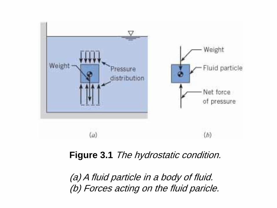
Figure 3.1 The hydrostatic condition. (a) A fluid particle in a body of fluid. (b) Forces acting on the fluid paricle.
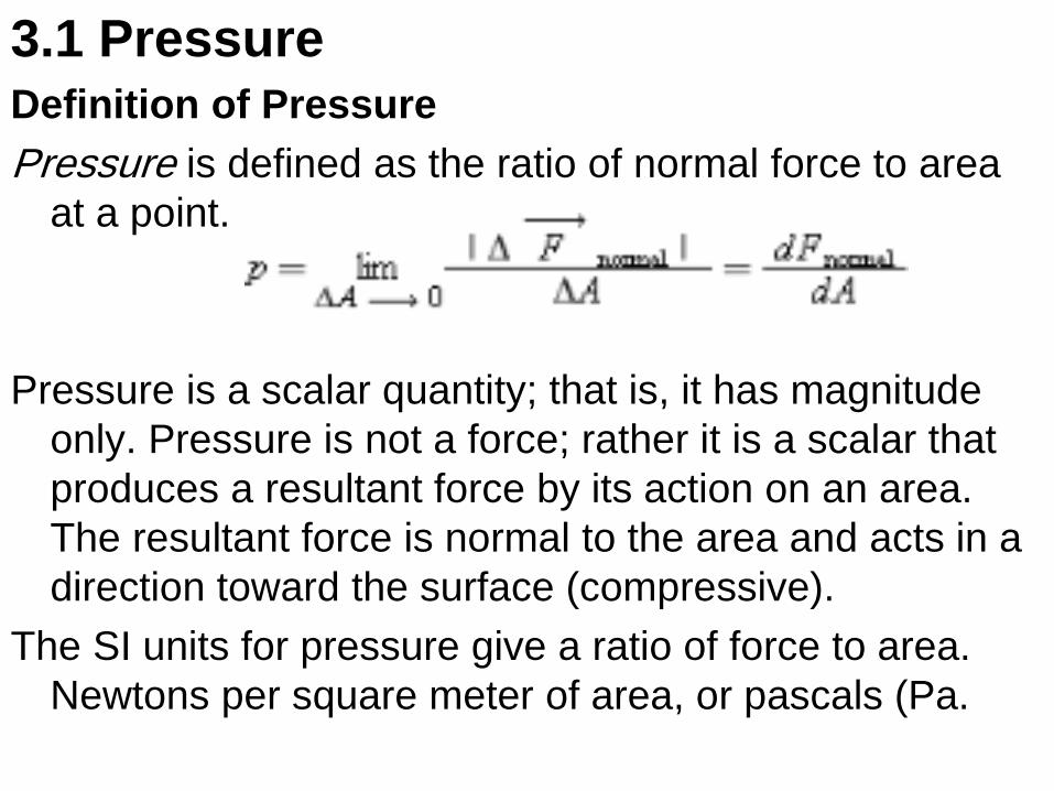
3.1 Pressure Definition of Pressure
Pressure is defined as the ratio of normal force to area
at a point.
Pressure is a scalar quantity; that is, it has magnitude
only. Pressure is not a force; rather it is a scalar that
produces a resultant force by its action on an area.
The resultant force is normal to the area and acts in a
direction toward the surface (compressive).
The SI units for pressure give a ratio of force to area.
Newtons per square meter of area, or pascals (Pa.
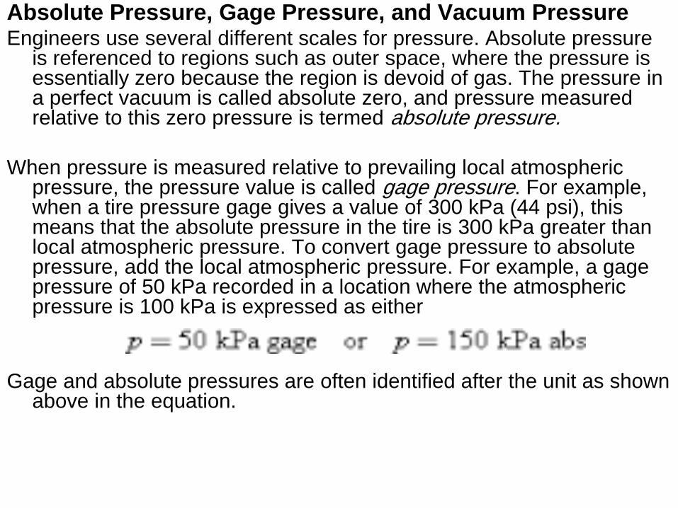
Absolute Pressure, Gage Pressure, and Vacuum Pressure Engineers use several different scales for pressure. Absolute pressure
is referenced to regions such as outer space, where the pressure is essentially zero because the region is devoid of gas. The pressure in a perfect vacuum is called absolute zero, and pressure measured relative to this zero pressure is termed absolute pressure.
When pressure is measured relative to prevailing local atmospheric
pressure, the pressure value is called gage pressure. For example, when a tire pressure gage gives a value of 300 kPa (44 psi), this means that the absolute pressure in the tire is 300 kPa greater than local atmospheric pressure. To convert gage pressure to absolute pressure, add the local atmospheric pressure. For example, a gage pressure of 50 kPa recorded in a location where the atmospheric pressure is 100 kPa is expressed as either
Gage and absolute pressures are often identified after the unit as shown above in the equation.
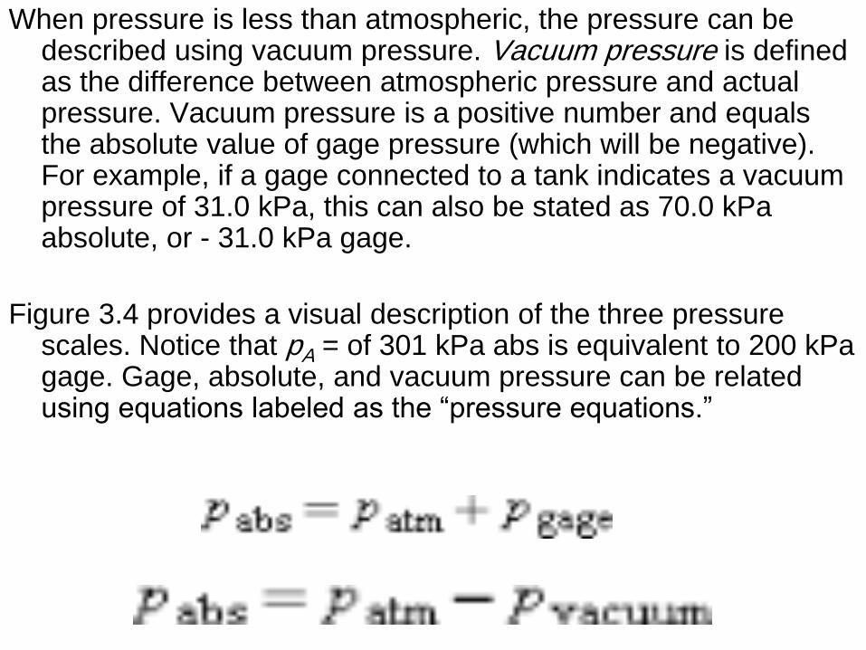
When pressure is less than atmospheric, the pressure can be described using vacuum pressure. Vacuum pressure is defined as the difference between atmospheric pressure and actual pressure. Vacuum pressure is a positive number and equals the absolute value of gage pressure (which will be negative). For example, if a gage connected to a tank indicates a vacuum pressure of 31.0 kPa, this can also be stated as 70.0 kPa absolute, or - 31.0 kPa gage.
Figure 3.4 provides a visual description of the three pressure scales. Notice that pA = of 301 kPa abs is equivalent to 200 kPa gage. Gage, absolute, and vacuum pressure can be related using equations labeled as the “pressure equations.”
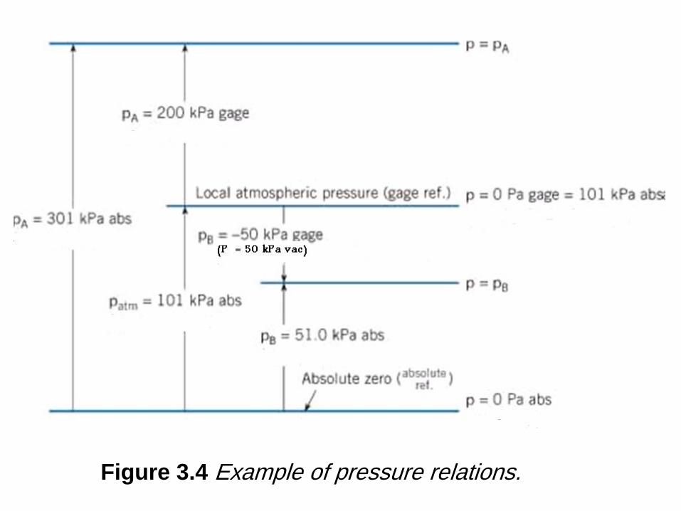
Figure 3.4 Example of pressure relations.
• Hydraulic Machines
• A hydraulic machine uses components such as pistons, pumps, and hoses to transmit forces and energy using fluids. Hydraulic machines are applied, for example, to braking systems, forklift trucks, power steering systems, and airplane control systems 3. Hydraulic machines provide an example of Pascal's law. This law states that pressure applied to an enclosed and continuous body of fluid is transmitted undiminished to every portion of that fluid and to the walls of the containing vessel.
• Hydraulic machines provide mechanical advantage. For example, a person using a hydraulic jack can lift a much larger load, as shown in Example 3.1.
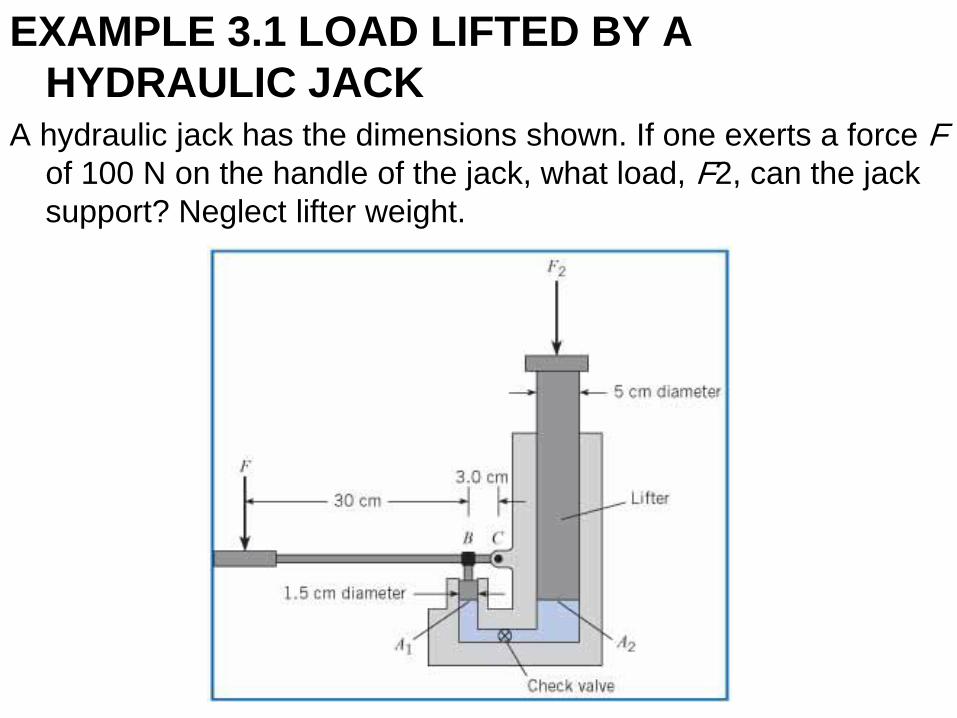
EXAMPLE 3.1 LOAD LIFTED BY A
HYDRAULIC JACK A hydraulic jack has the dimensions shown. If one exerts a force F
of 100 N on the handle of the jack, what load, F2, can the jack
support? Neglect lifter weight.
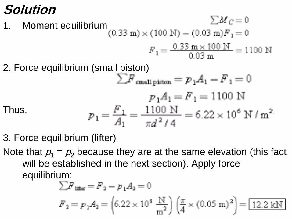
Solution 1. Moment equilibrium
2. Force equilibrium (small piston)
Thus,
3. Force equilibrium (lifter)
Note that p1 = p2 because they are at the same elevation (this fact
will be established in the next section). Apply force
equilibrium:
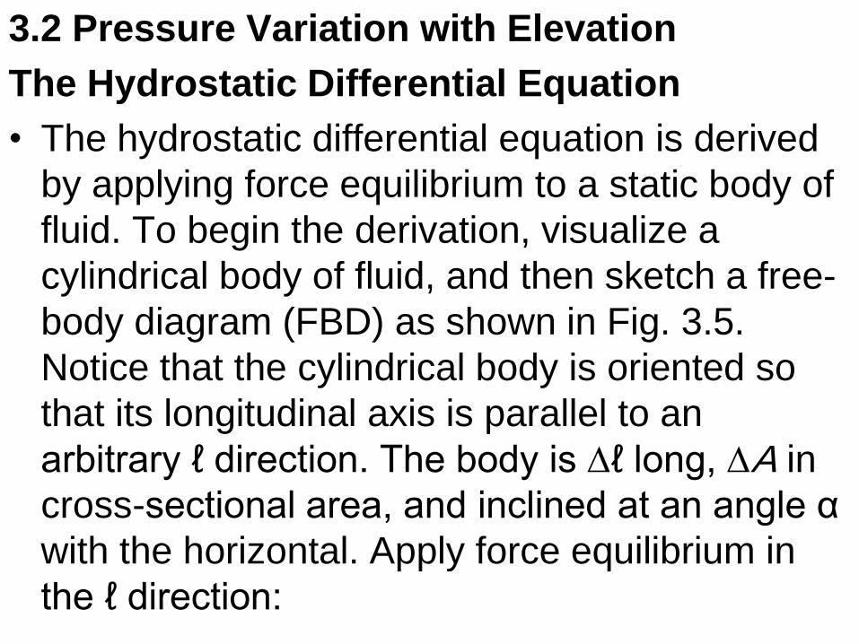
3.2 Pressure Variation with Elevation
The Hydrostatic Differential Equation
• The hydrostatic differential equation is derived
by applying force equilibrium to a static body of
fluid. To begin the derivation, visualize a
cylindrical body of fluid, and then sketch a free-
body diagram (FBD) as shown in Fig. 3.5.
Notice that the cylindrical body is oriented so
that its longitudinal axis is parallel to an
arbitrary ℓ direction. The body is Dℓ long, DA in
cross-sectional area, and inclined at an angle α
with the horizontal. Apply force equilibrium in
the ℓ direction:
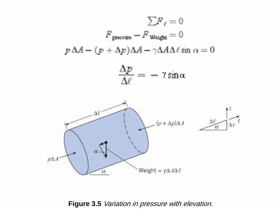
Figure 3.5 Variation in pressure with elevation.
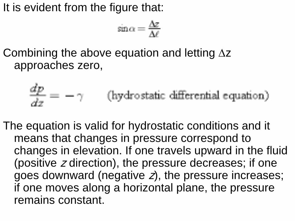
It is evident from the figure that:
Combining the above equation and letting Dz approaches zero,
The equation is valid for hydrostatic conditions and it means that changes in pressure correspond to changes in elevation. If one travels upward in the fluid (positive z direction), the pressure decreases; if one goes downward (negative z), the pressure increases; if one moves along a horizontal plane, the pressure remains constant.
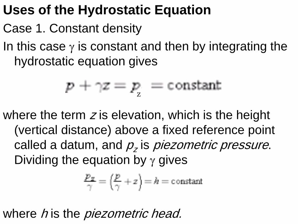
Uses of the Hydrostatic Equation
Case 1. Constant density
In this case g is constant and then by integrating the
hydrostatic equation gives
where the term z is elevation, which is the height
(vertical distance) above a fixed reference point
called a datum, and pz is piezometric pressure.
Dividing the equation by g gives
where h is the piezometric head.
Since h is constant in the previous equation, then
where the subscripts 1 and 2 identify any two points in a static fluid of constant density. Multiplying the equation by g gives
The hydrostatic equation is given by either of the above equations are equivalent, because any one of the equations can be used to derive the other. The hydrostatic equation is valid for any constant density fluid in hydrostatic equilibrium.
To calculate piezometric head or piezometric pressure, an engineer identifies a specific location in a body of fluid and then uses the value of pressure and elevation at that location
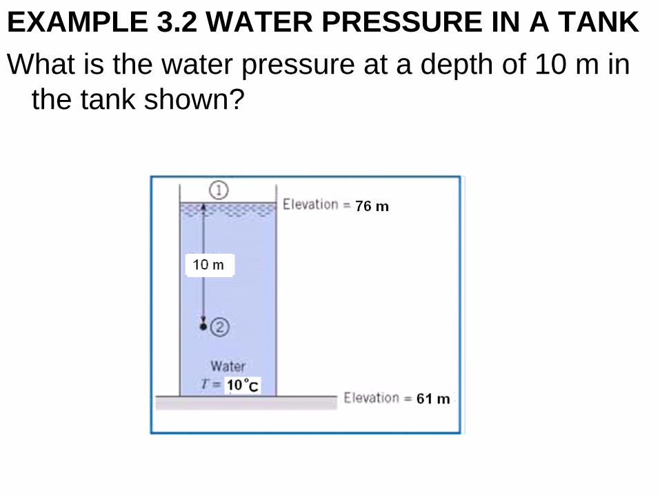
EXAMPLE 3.2 WATER PRESSURE IN A TANK
What is the water pressure at a depth of 10 m in
the tank shown?
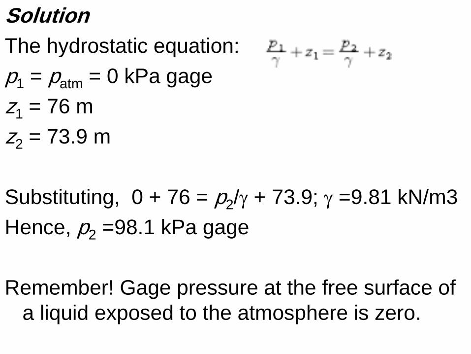
Solution
The hydrostatic equation:
p1 = patm = 0 kPa gage
z1 = 76 m
z2 = 73.9 m
Substituting, 0 + 76 = p2/g + 73.9; g =9.81 kN/m3
Hence, p2 =98.1 kPa gage
Remember! Gage pressure at the free surface of
a liquid exposed to the atmosphere is zero.
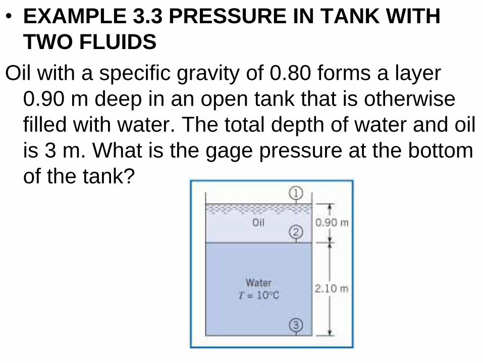
• EXAMPLE 3.3 PRESSURE IN TANK WITH
TWO FLUIDS
Oil with a specific gravity of 0.80 forms a layer
0.90 m deep in an open tank that is otherwise
filled with water. The total depth of water and oil
is 3 m. What is the gage pressure at the bottom
of the tank?
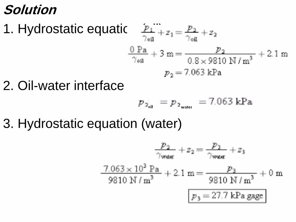
Solution
1. Hydrostatic equation (oil)
2. Oil-water interface
3. Hydrostatic equation (water)
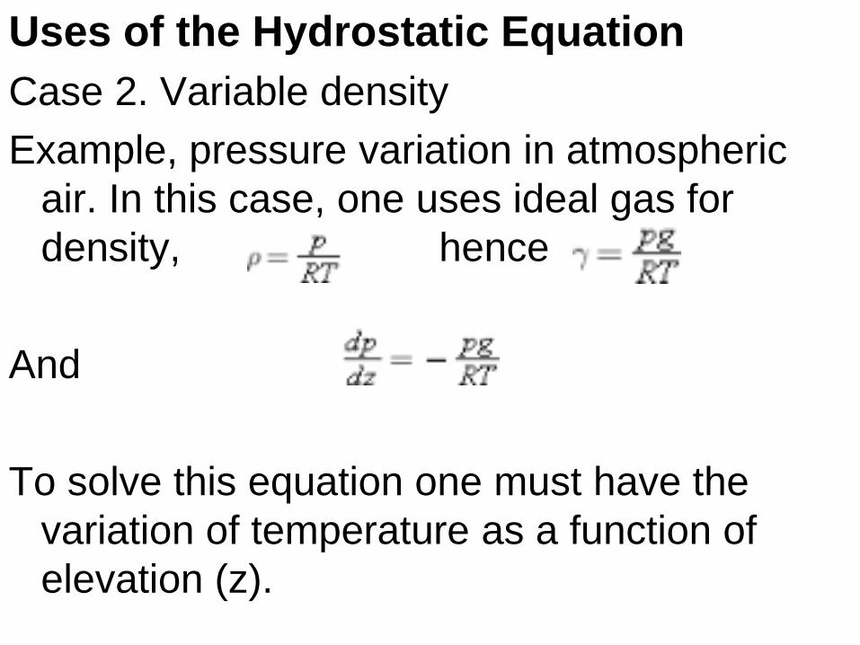
Uses of the Hydrostatic Equation
Case 2. Variable density
Example, pressure variation in atmospheric
air. In this case, one uses ideal gas for
density, hence
And
To solve this equation one must have the
variation of temperature as a function of
elevation (z).
3.3 Pressure Measurements
This section describes five scientific instruments for measuring pressure: the barometer, Bourdon-tube gage, piezometer, manometer, and transducer.
1) Barometer
An instrument that is used to measure atmospheric pressure is called a barometer. The most common types are the mercury barometer and the aneroid barometer. A mercury barometer is made by inverting a mercury-filled tube in a container of mercury as shown in Fig. 3.8. The pressure at the top of the mercury barometer will be the vapor pressure of mercury, which is very small: pv = 2.4 × 10⁻⁶ atm at 20°C. Thus, atmospheric pressure will push the mercury up the tube to a height h. The mercury barometer is analyzed by applying the hydrostatic equation:
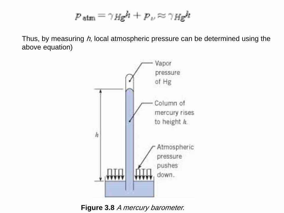
Figure 3.8 A mercury barometer.
Thus, by measuring h, local atmospheric pressure can be determined using the
above equation)
2) Bourdon-Tube Gage
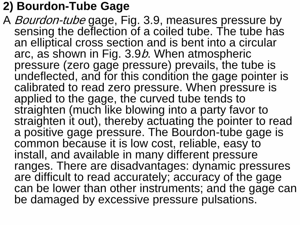
A Bourdon-tube gage, Fig. 3.9, measures pressure by sensing the deflection of a coiled tube. The tube has an elliptical cross section and is bent into a circular arc, as shown in Fig. 3.9b. When atmospheric pressure (zero gage pressure) prevails, the tube is undeflected, and for this condition the gage pointer is calibrated to read zero pressure. When pressure is applied to the gage, the curved tube tends to straighten (much like blowing into a party favor to straighten it out), thereby actuating the pointer to read a positive gage pressure. The Bourdon-tube gage is common because it is low cost, reliable, easy to install, and available in many different pressure ranges. There are disadvantages: dynamic pressures are difficult to read accurately; accuracy of the gage can be lower than other instruments; and the gage can be damaged by excessive pressure pulsations.
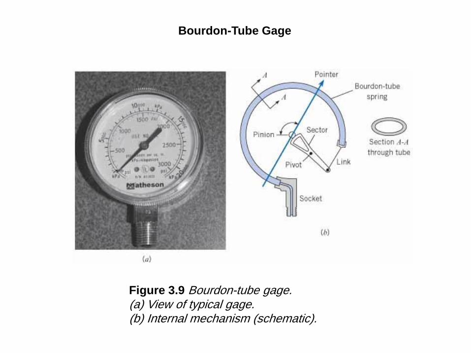
Figure 3.9 Bourdon-tube gage. (a) View of typical gage. (b) Internal mechanism (schematic).
Bourdon-Tube Gage
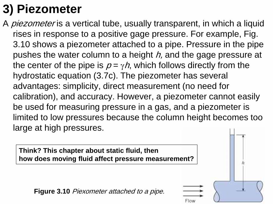
3) Piezometer A piezometer is a vertical tube, usually transparent, in which a liquid
rises in response to a positive gage pressure. For example, Fig.
3.10 shows a piezometer attached to a pipe. Pressure in the pipe
pushes the water column to a height h, and the gage pressure at
the center of the pipe is p = gh, which follows directly from the
hydrostatic equation (3.7c). The piezometer has several
advantages: simplicity, direct measurement (no need for
calibration), and accuracy. However, a piezometer cannot easily
be used for measuring pressure in a gas, and a piezometer is
limited to low pressures because the column height becomes too
large at high pressures.
Figure 3.10 Piexometer attached to a pipe.
Think? This chapter about static fluid, then
how does moving fluid affect pressure measurement?
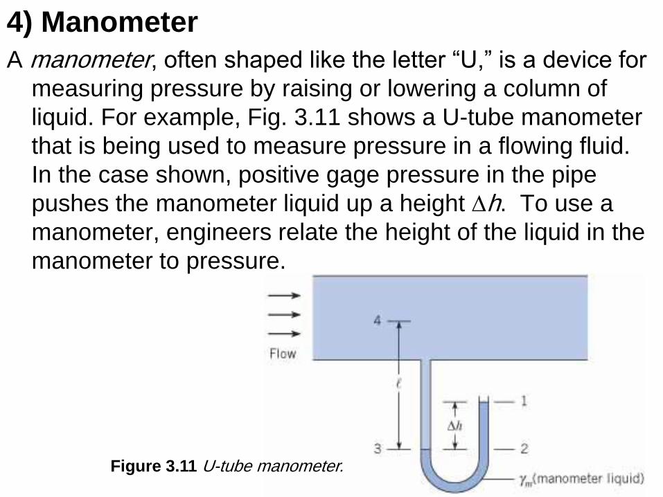
4) Manometer
A manometer, often shaped like the letter “U,” is a device for
measuring pressure by raising or lowering a column of
liquid. For example, Fig. 3.11 shows a U-tube manometer
that is being used to measure pressure in a flowing fluid.
In the case shown, positive gage pressure in the pipe
pushes the manometer liquid up a height Dh. To use a
manometer, engineers relate the height of the liquid in the
manometer to pressure.
Figure 3.11 U-tube manometer.
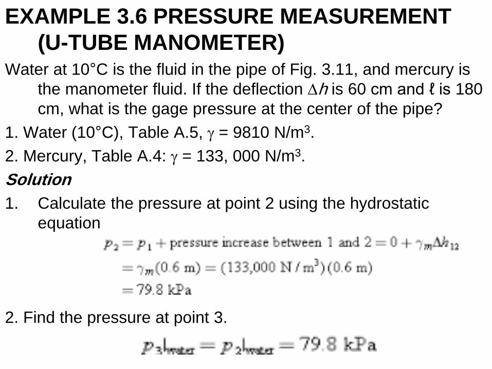
EXAMPLE 3.6 PRESSURE MEASUREMENT
(U-TUBE MANOMETER) Water at 10°C is the fluid in the pipe of Fig. 3.11, and mercury is
the manometer fluid. If the deflection Dh is 60 cm and ℓ is 180
cm, what is the gage pressure at the center of the pipe?
1. Water (10°C), Table A.5, g = 9810 N/m3.
2. Mercury, Table A.4: g = 133, 000 N/m3.
Solution
1. Calculate the pressure at point 2 using the hydrostatic
equation
2. Find the pressure at point 3.
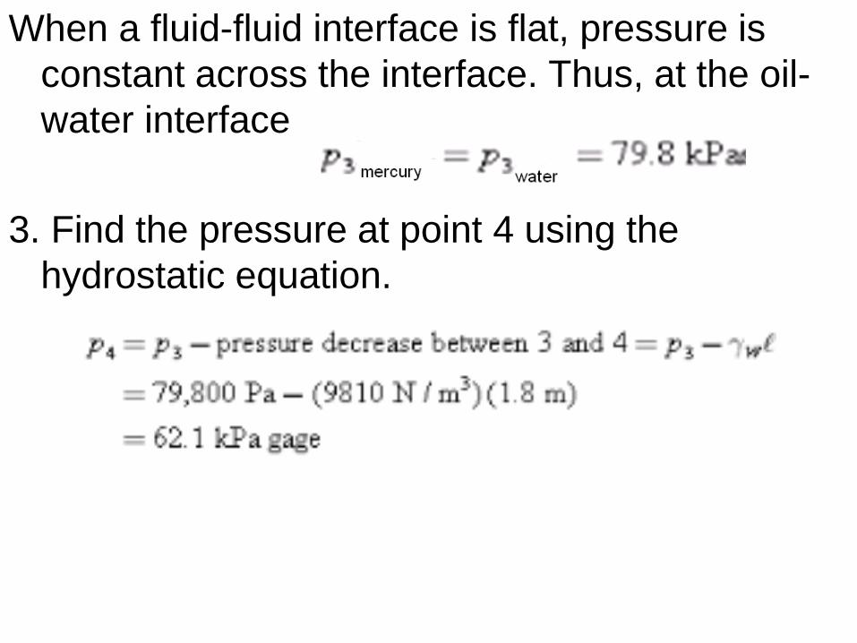
When a fluid-fluid interface is flat, pressure is
constant across the interface. Thus, at the oil-
water interface
3. Find the pressure at point 4 using the
hydrostatic equation.
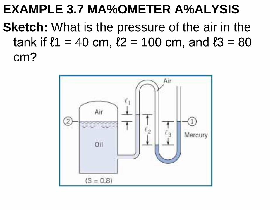
EXAMPLE 3.7 MA%OMETER A%ALYSIS
Sketch: What is the pressure of the air in the
tank if ℓ1 = 40 cm, ℓ2 = 100 cm, and ℓ3 = 80
cm?
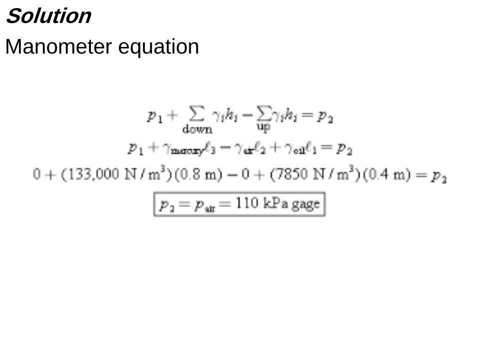
Solution
Manometer equation
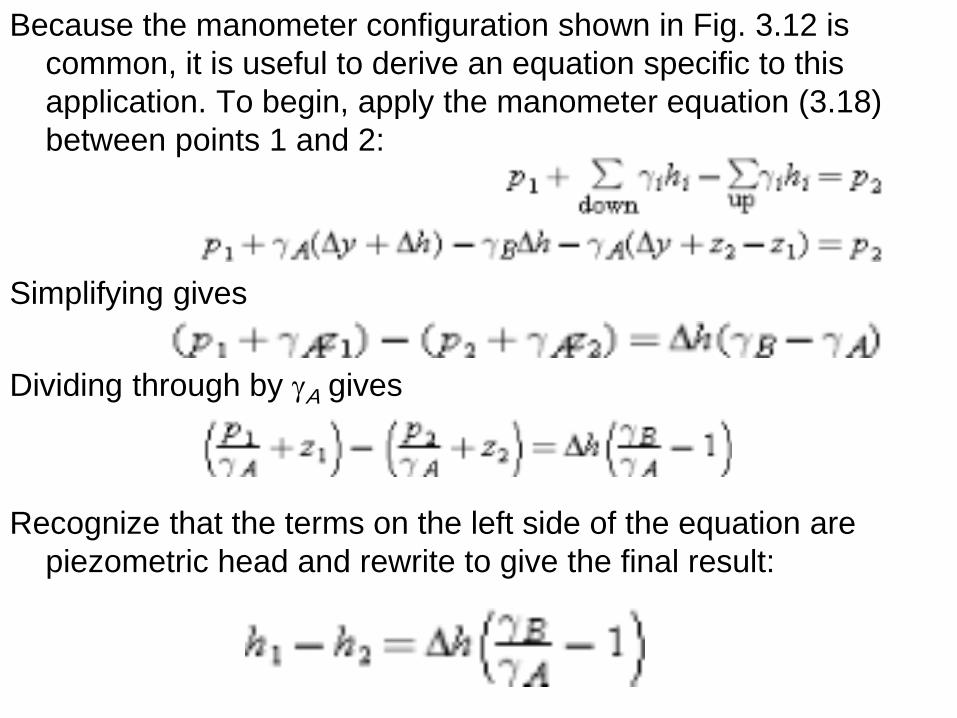
Because the manometer configuration shown in Fig. 3.12 is
common, it is useful to derive an equation specific to this
application. To begin, apply the manometer equation (3.18)
between points 1 and 2:
Simplifying gives
Dividing through by gA gives
Recognize that the terms on the left side of the equation are
piezometric head and rewrite to give the final result:
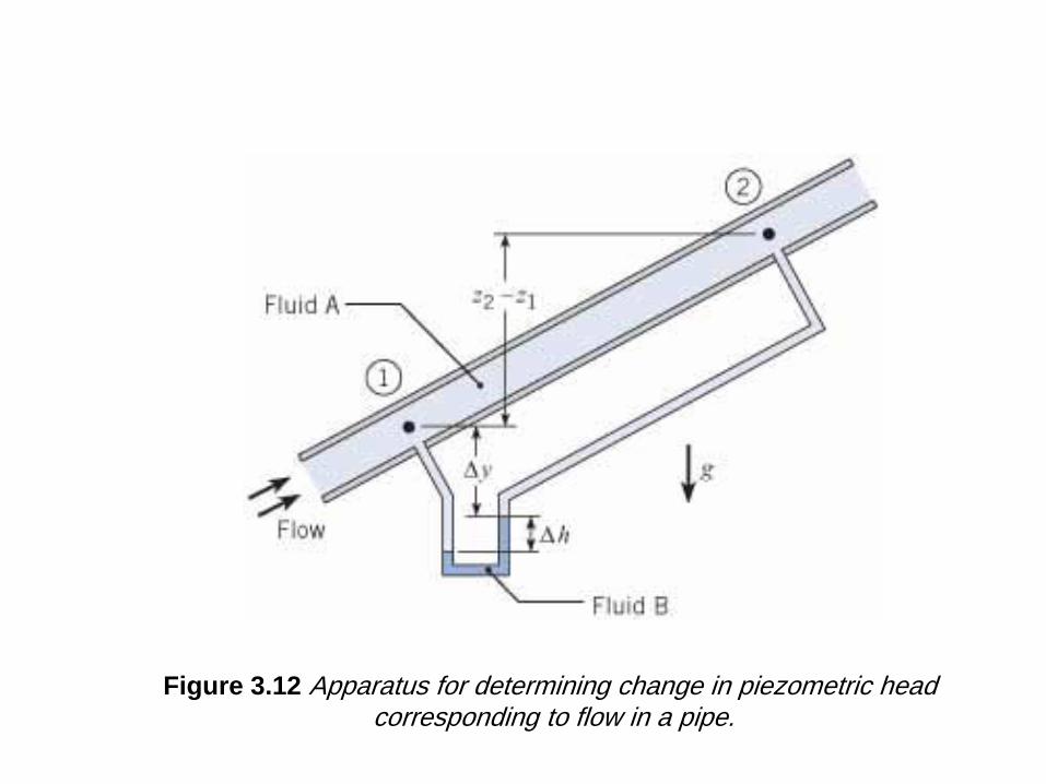
Figure 3.12 Apparatus for determining change in piezometric head corresponding to flow in a pipe.
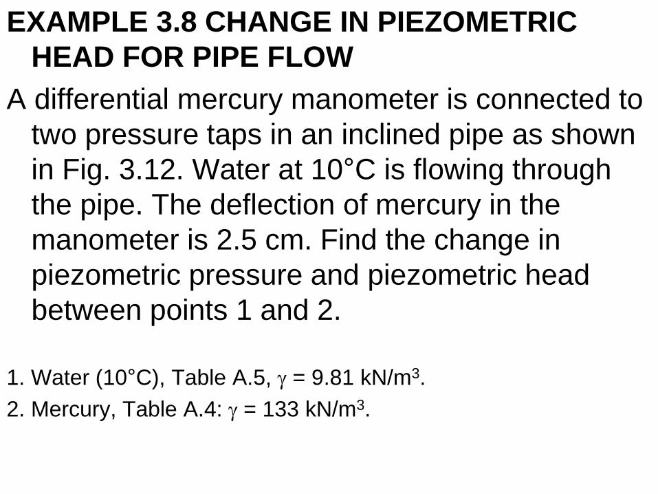
EXAMPLE 3.8 CHANGE IN PIEZOMETRIC
HEAD FOR PIPE FLOW
A differential mercury manometer is connected to
two pressure taps in an inclined pipe as shown
in Fig. 3.12. Water at 10°C is flowing through
the pipe. The deflection of mercury in the
manometer is 2.5 cm. Find the change in
piezometric pressure and piezometric head
between points 1 and 2.
1. Water (10°C), Table A.5, g = 9.81 kN/m3.
2. Mercury, Table A.4: g = 133 kN/m3.
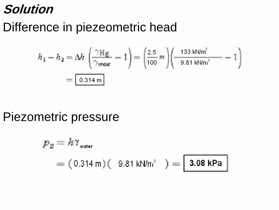
Solution
Difference in piezeometric head
Piezometric pressure
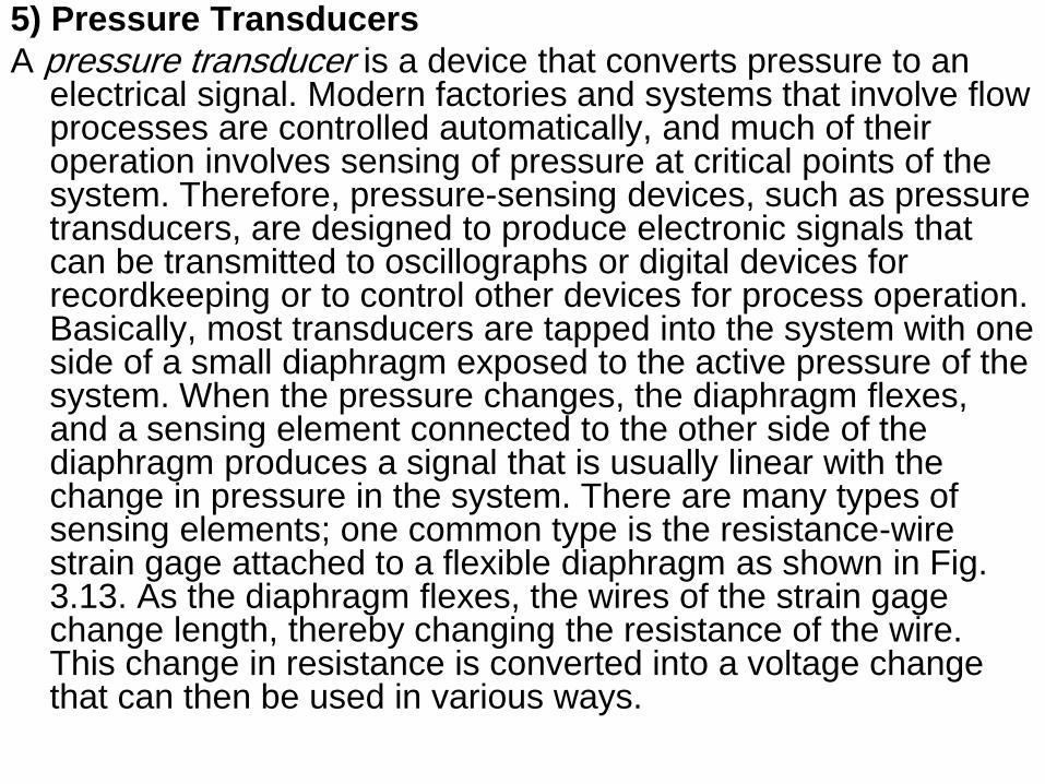
5) Pressure Transducers
A pressure transducer is a device that converts pressure to an electrical signal. Modern factories and systems that involve flow processes are controlled automatically, and much of their operation involves sensing of pressure at critical points of the system. Therefore, pressure-sensing devices, such as pressure transducers, are designed to produce electronic signals that can be transmitted to oscillographs or digital devices for recordkeeping or to control other devices for process operation. Basically, most transducers are tapped into the system with one side of a small diaphragm exposed to the active pressure of the system. When the pressure changes, the diaphragm flexes, and a sensing element connected to the other side of the diaphragm produces a signal that is usually linear with the change in pressure in the system. There are many types of sensing elements; one common type is the resistance-wire strain gage attached to a flexible diaphragm as shown in Fig. 3.13. As the diaphragm flexes, the wires of the strain gage change length, thereby changing the resistance of the wire. This change in resistance is converted into a voltage change that can then be used in various ways.
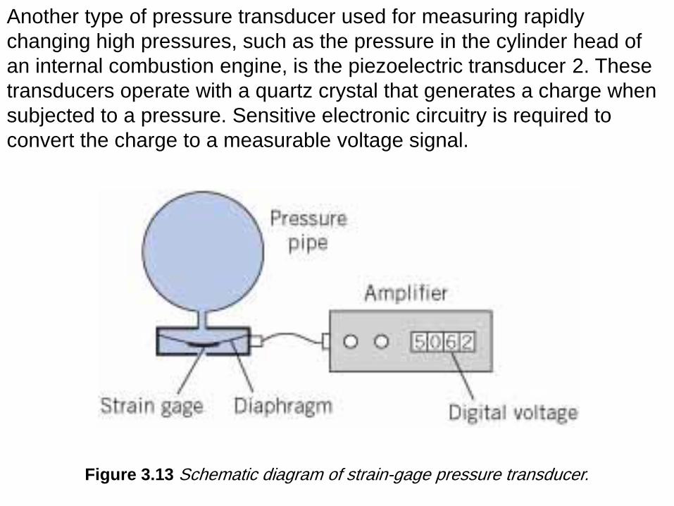
Figure 3.13 Schematic diagram of strain-gage pressure transducer.
Another type of pressure transducer used for measuring rapidly
changing high pressures, such as the pressure in the cylinder head of
an internal combustion engine, is the piezoelectric transducer 2. These
transducers operate with a quartz crystal that generates a charge when
subjected to a pressure. Sensitive electronic circuitry is required to
convert the charge to a measurable voltage signal.
3.4 Forces on Plane Surfaces (Panels)
This section explains how to represent hydrostatic pressure
distributions on one face of a panel with a resultant force that
passes through a point called the center of pressure.
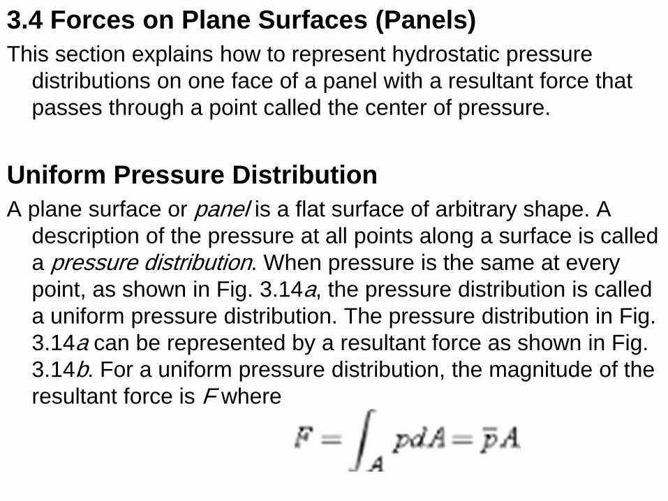
Uniform Pressure Distribution
A plane surface or panel is a flat surface of arbitrary shape. A
description of the pressure at all points along a surface is called
a pressure distribution. When pressure is the same at every
point, as shown in Fig. 3.14a, the pressure distribution is called
a uniform pressure distribution. The pressure distribution in Fig.
3.14a can be represented by a resultant force as shown in Fig.
3.14b. For a uniform pressure distribution, the magnitude of the
resultant force is F where
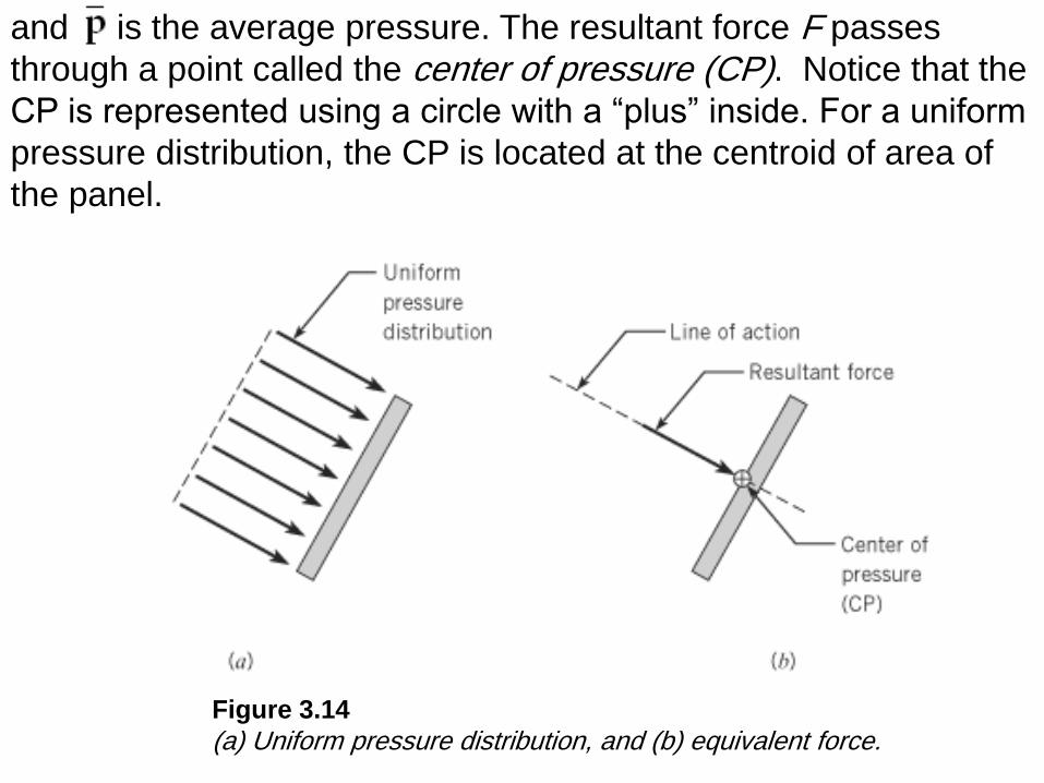
Figure 3.14
(a) Uniform pressure distribution, and (b) equivalent force.
and is the average pressure. The resultant force F passes
through a point called the center of pressure (CP). Notice that the
CP is represented using a circle with a “plus” inside. For a uniform
pressure distribution, the CP is located at the centroid of area of
the panel.
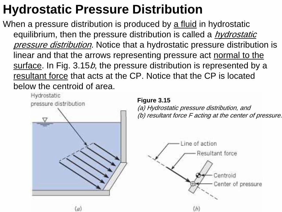
Hydrostatic Pressure Distribution When a pressure distribution is produced by a fluid in hydrostatic
equilibrium, then the pressure distribution is called a hydrostatic pressure distribution. Notice that a hydrostatic pressure distribution is
linear and that the arrows representing pressure act normal to the
surface. In Fig. 3.15b, the pressure distribution is represented by a
resultant force that acts at the CP. Notice that the CP is located
below the centroid of area.
Figure 3.15
(a) Hydrostatic pressure distribution, and (b) resultant force F acting at the center of pressure.
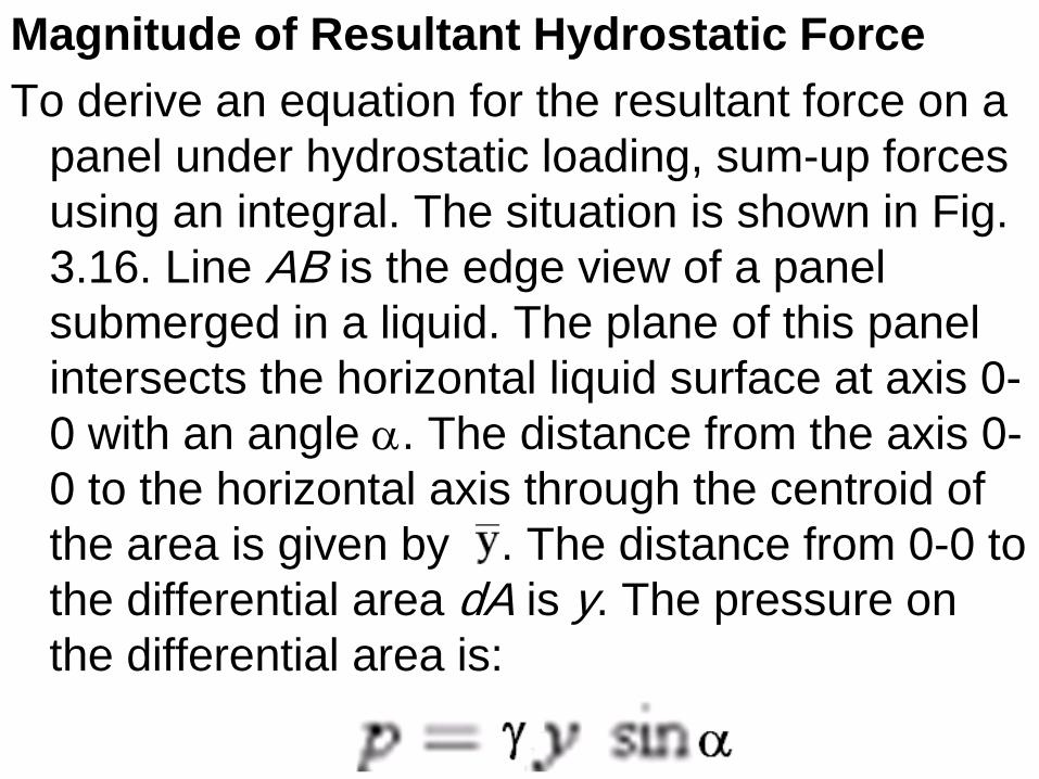
Magnitude of Resultant Hydrostatic Force
To derive an equation for the resultant force on a
panel under hydrostatic loading, sum-up forces
using an integral. The situation is shown in Fig.
3.16. Line AB is the edge view of a panel
submerged in a liquid. The plane of this panel
intersects the horizontal liquid surface at axis 0-
0 with an angle a. The distance from the axis 0-
0 to the horizontal axis through the centroid of
the area is given by . The distance from 0-0 to
the differential area dA is y. The pressure on
the differential area is:
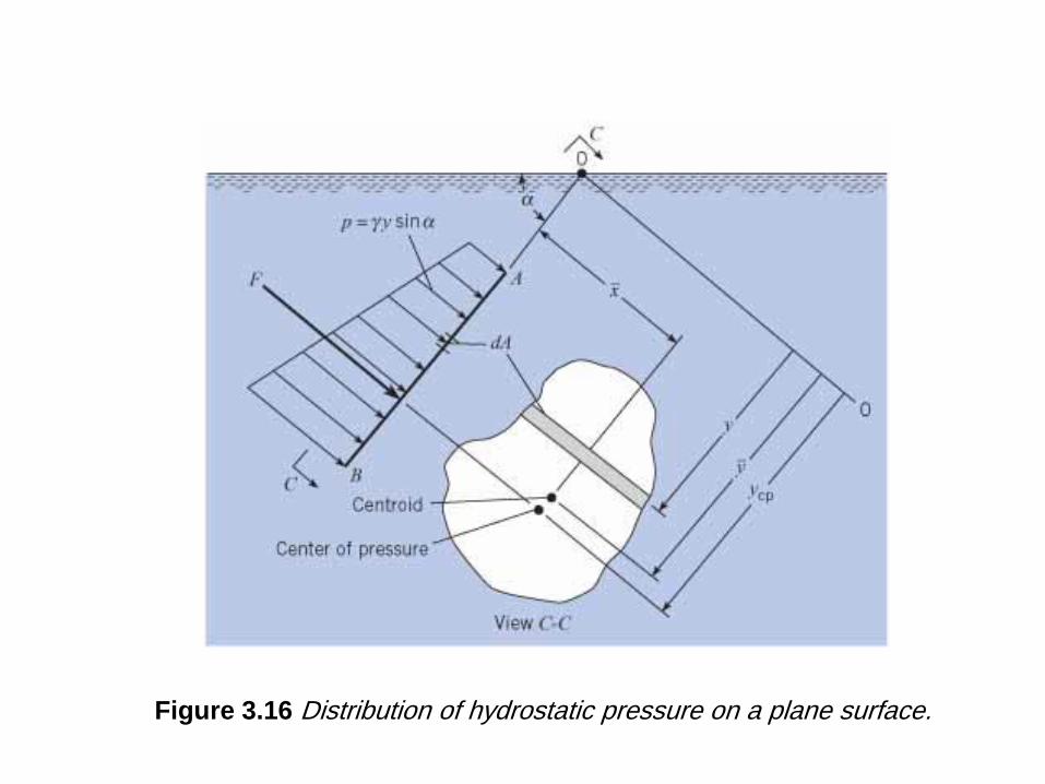
Figure 3.16 Distribution of hydrostatic pressure on a plane surface.
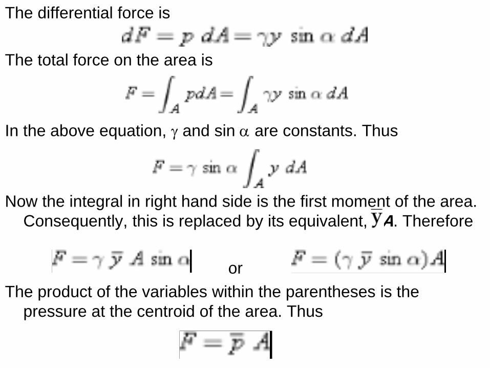
The differential force is
The total force on the area is
In the above equation, g and sin a are constants. Thus
Now the integral in right hand side is the first moment of the area.
Consequently, this is replaced by its equivalent, A. Therefore
or
The product of the variables within the parentheses is the
pressure at the centroid of the area. Thus
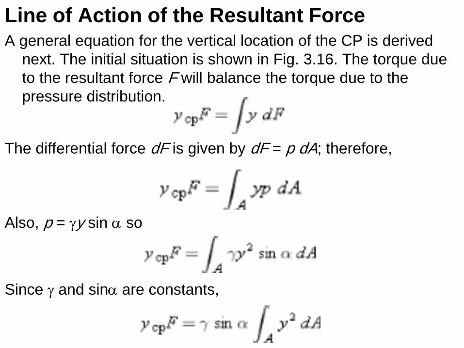
Line of Action of the Resultant Force A general equation for the vertical location of the CP is derived
next. The initial situation is shown in Fig. 3.16. The torque due
to the resultant force F will balance the torque due to the
pressure distribution.
The differential force dF is given by dF = p dA; therefore,
Also, p = gy sin a so
Since g and sina are constants,
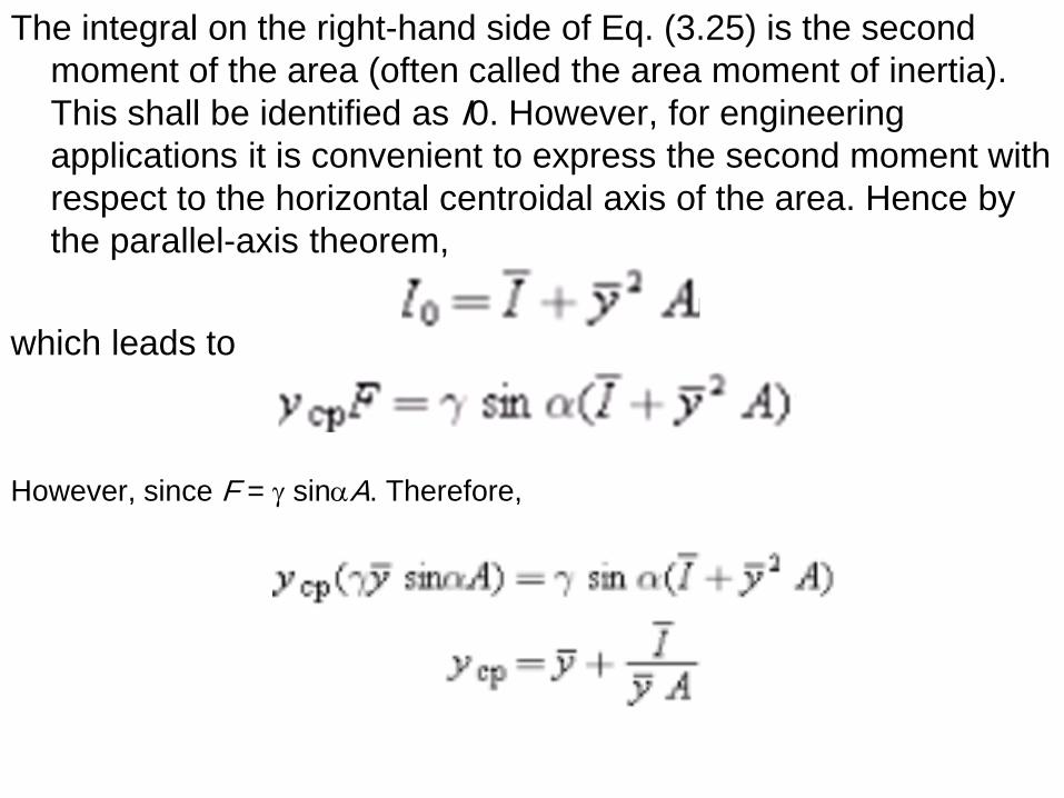
The integral on the right-hand side of Eq. (3.25) is the second
moment of the area (often called the area moment of inertia).
This shall be identified as I0. However, for engineering
applications it is convenient to express the second moment with
respect to the horizontal centroidal axis of the area. Hence by
the parallel-axis theorem,
which leads to
However, since F = g sinaA. Therefore,
Notes on previous equations The area moment of inertia is taken about a horizontal axis that
passes through the centroid of area. Formulas for are presented in Fig. A.1. The slant distance measures the length from the surface of the liquid to the centroid of the panel along an axis that is aligned with the “slant of the panel” as shown in Fig. 3.16.
It is seen that the Center of Pressure (CP) will be situated below the centroid. The distance between the CP and the centroid depends on the depth of submersion, which is characterized by
and on the panel geometry, which is characterized by /A.
Due to assumptions in the derivations, there are several limitations on the previous equations. First, they only apply to a single fluid of constant density. Second, the pressure at the liquid surface needs to be p = 0 gage to correctly locate the CP. Third, the last equation gives only the vertical location of the CP, not the lateral location.
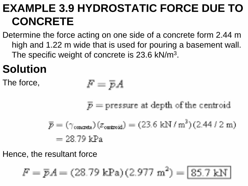
EXAMPLE 3.9 HYDROSTATIC FORCE DUE TO
CONCRETE Determine the force acting on one side of a concrete form 2.44 m
high and 1.22 m wide that is used for pouring a basement wall.
The specific weight of concrete is 23.6 kN/m3.
Solution The force,
Hence, the resultant force
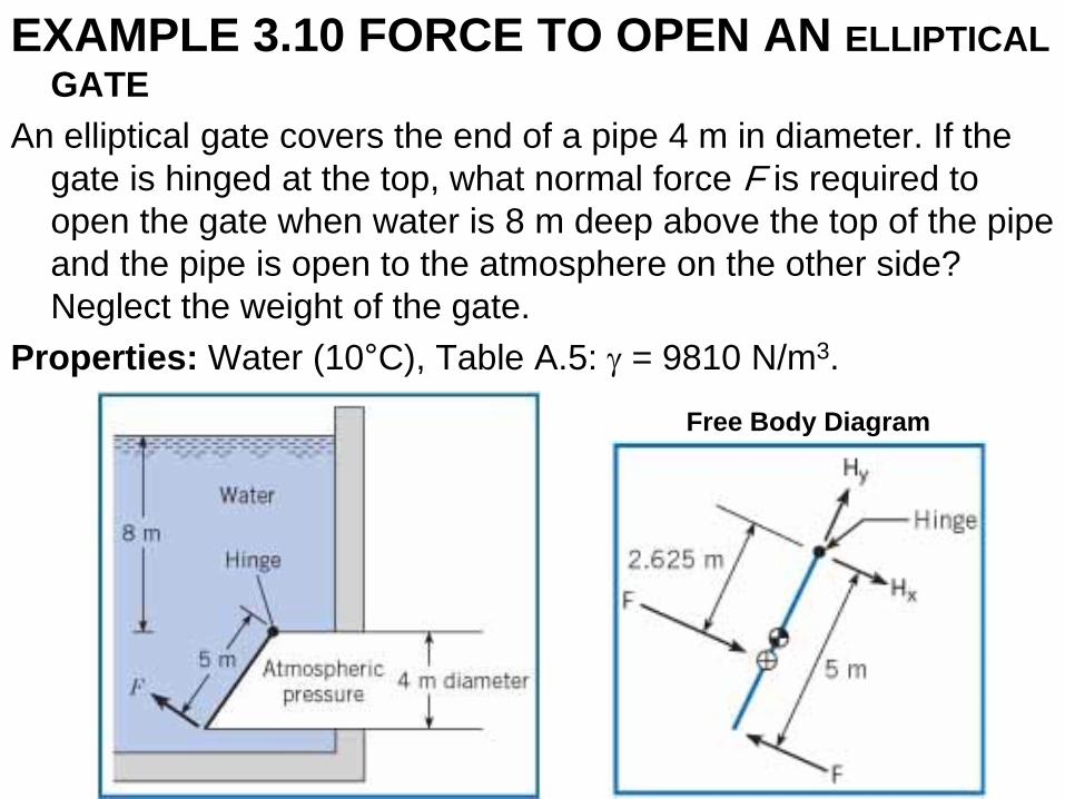
EXAMPLE 3.10 FORCE TO OPEN AN ELLIPTICAL
GATE
An elliptical gate covers the end of a pipe 4 m in diameter. If the
gate is hinged at the top, what normal force F is required to
open the gate when water is 8 m deep above the top of the pipe
and the pipe is open to the atmosphere on the other side?
Neglect the weight of the gate.
Properties: Water (10°C), Table A.5: g = 9810 N/m3.
Free Body Diagram
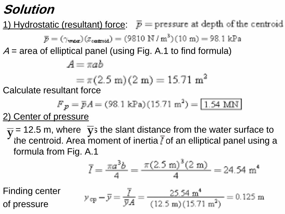
Solution 1) Hydrostatic (resultant) force:
A = area of elliptical panel (using Fig. A.1 to find formula)
Calculate resultant force
2) Center of pressure
= 12.5 m, where is the slant distance from the water surface to
the centroid. Area moment of inertia of an elliptical panel using a
formula from Fig. A.1
Finding center
of pressure
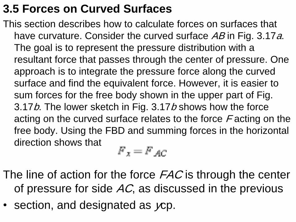
3.5 Forces on Curved Surfaces
This section describes how to calculate forces on surfaces that
have curvature. Consider the curved surface AB in Fig. 3.17a.
The goal is to represent the pressure distribution with a
resultant force that passes through the center of pressure. One
approach is to integrate the pressure force along the curved
surface and find the equivalent force. However, it is easier to
sum forces for the free body shown in the upper part of Fig.
3.17b. The lower sketch in Fig. 3.17b shows how the force
acting on the curved surface relates to the force F acting on the
free body. Using the FBD and summing forces in the horizontal
direction shows that
The line of action for the force FAC is through the center
of pressure for side AC, as discussed in the previous
• section, and designated as ycp.
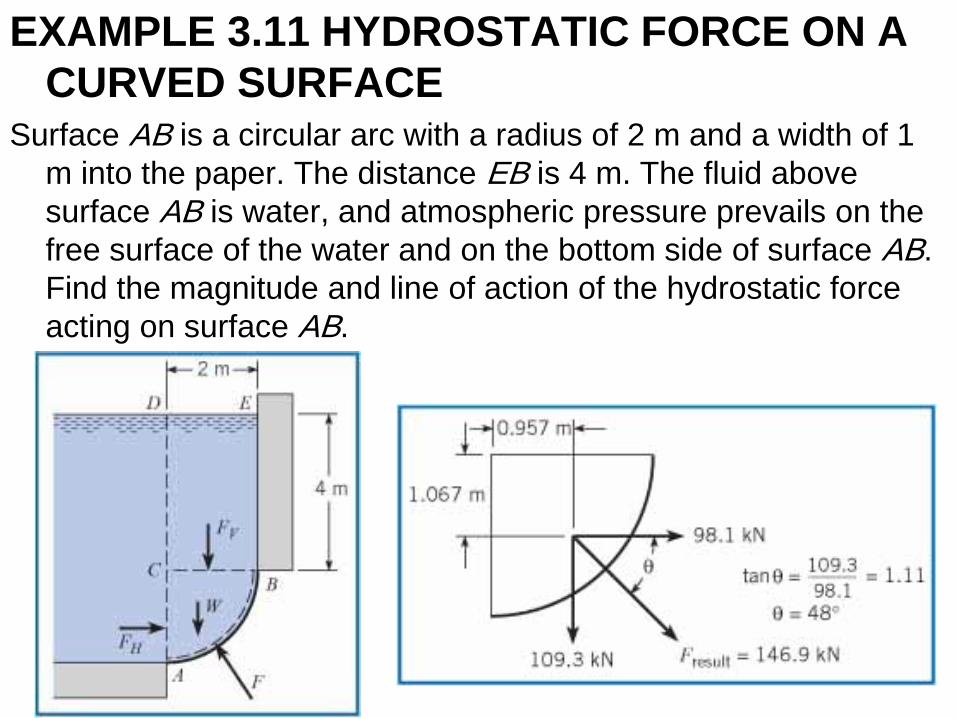
EXAMPLE 3.11 HYDROSTATIC FORCE ON A
CURVED SURFACE Surface AB is a circular arc with a radius of 2 m and a width of 1
m into the paper. The distance EB is 4 m. The fluid above
surface AB is water, and atmospheric pressure prevails on the
free surface of the water and on the bottom side of surface AB.
Find the magnitude and line of action of the hydrostatic force
acting on surface AB.
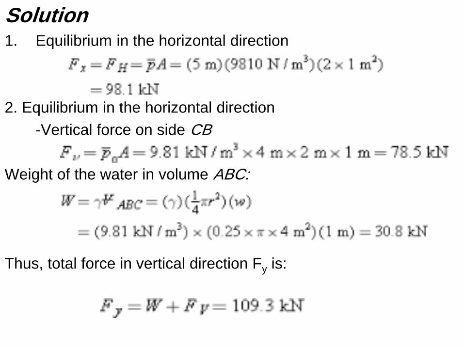
Solution 1. Equilibrium in the horizontal direction
2. Equilibrium in the horizontal direction
-Vertical force on side CB
Weight of the water in volume ABC:
Thus, total force in vertical direction Fy is:
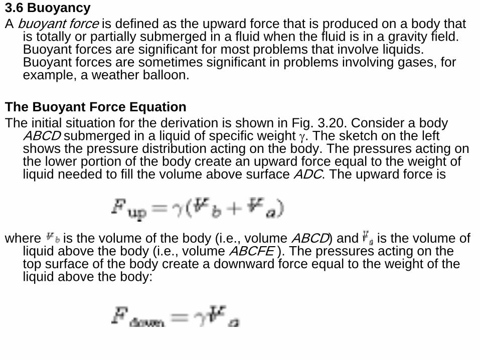
3.6 Buoyancy
A buoyant force is defined as the upward force that is produced on a body that is totally or partially submerged in a fluid when the fluid is in a gravity field. Buoyant forces are significant for most problems that involve liquids. Buoyant forces are sometimes significant in problems involving gases, for example, a weather balloon.
The Buoyant Force Equation
The initial situation for the derivation is shown in Fig. 3.20. Consider a body ABCD submerged in a liquid of specific weight g. The sketch on the left shows the pressure distribution acting on the body. The pressures acting on the lower portion of the body create an upward force equal to the weight of liquid needed to fill the volume above surface ADC. The upward force is
where is the volume of the body (i.e., volume ABCD) and is the volume of liquid above the body (i.e., volume ABCFE ). The pressures acting on the top surface of the body create a downward force equal to the weight of the liquid above the body:
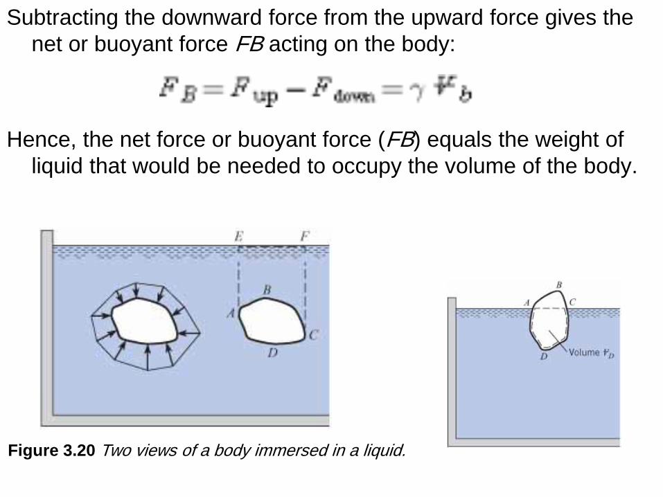
Subtracting the downward force from the upward force gives the
net or buoyant force FB acting on the body:
Hence, the net force or buoyant force (FB) equals the weight of
liquid that would be needed to occupy the volume of the body.
Figure 3.20 Two views of a body immersed in a liquid.
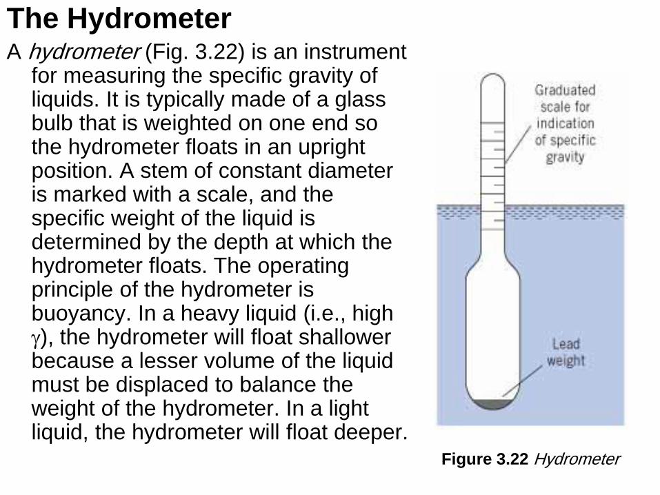
The Hydrometer A hydrometer (Fig. 3.22) is an instrument
for measuring the specific gravity of liquids. It is typically made of a glass bulb that is weighted on one end so the hydrometer floats in an upright position. A stem of constant diameter is marked with a scale, and the specific weight of the liquid is determined by the depth at which the hydrometer floats. The operating principle of the hydrometer is buoyancy. In a heavy liquid (i.e., high g), the hydrometer will float shallower because a lesser volume of the liquid must be displaced to balance the weight of the hydrometer. In a light liquid, the hydrometer will float deeper.
Figure 3.22 Hydrometer
3.7 Stability of Immersed and Floating Bodies
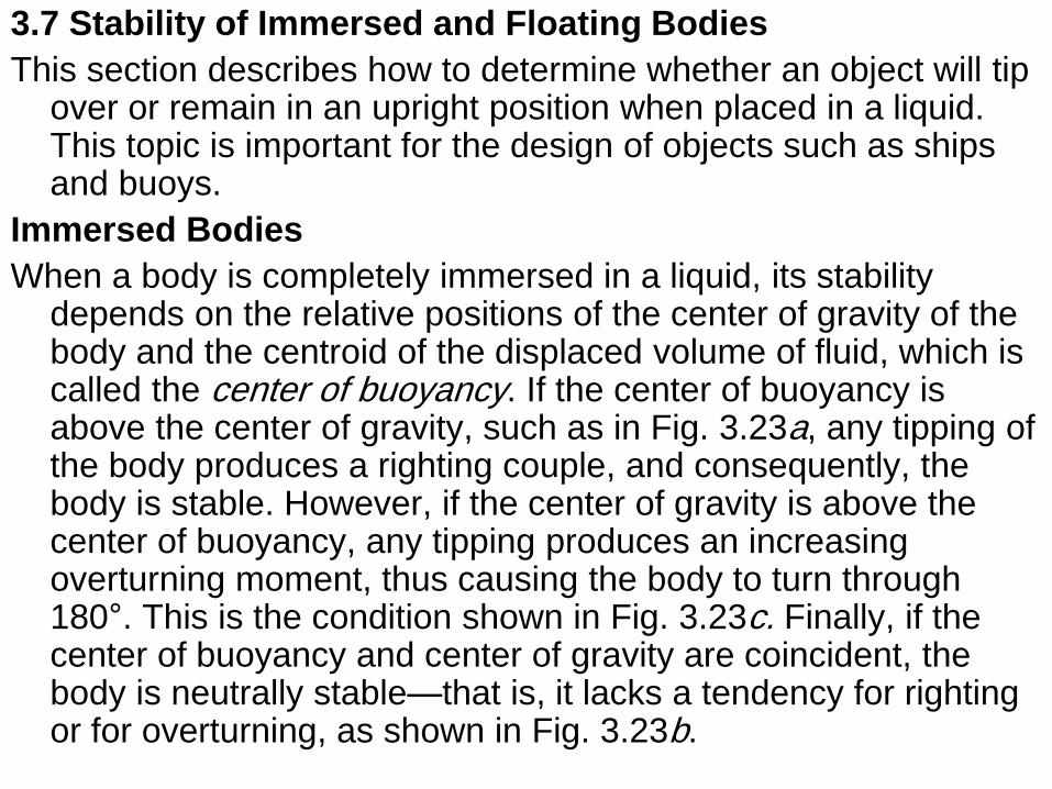
This section describes how to determine whether an object will tip over or remain in an upright position when placed in a liquid. This topic is important for the design of objects such as ships and buoys.
Immersed Bodies
When a body is completely immersed in a liquid, its stability depends on the relative positions of the center of gravity of the body and the centroid of the displaced volume of fluid, which is called the center of buoyancy. If the center of buoyancy is above the center of gravity, such as in Fig. 3.23a, any tipping of the body produces a righting couple, and consequently, the body is stable. However, if the center of gravity is above the center of buoyancy, any tipping produces an increasing overturning moment, thus causing the body to turn through 180°. This is the condition shown in Fig. 3.23c. Finally, if the center of buoyancy and center of gravity are coincident, the body is neutrally stable—that is, it lacks a tendency for righting or for overturning, as shown in Fig. 3.23b.
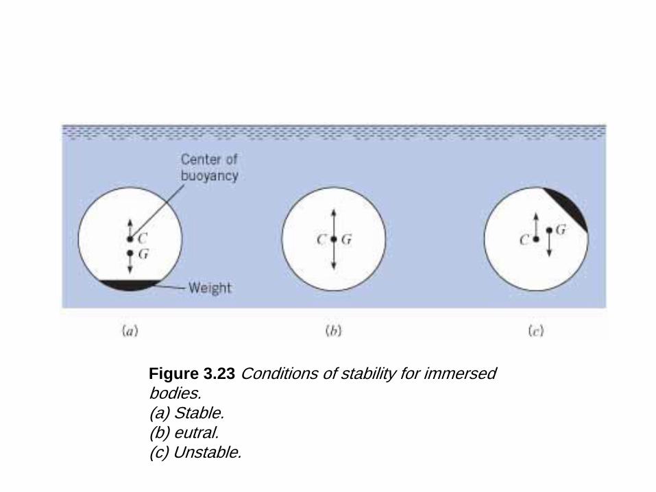
Figure 3.23 Conditions of stability for immersed bodies. (a) Stable. (b) eutral. (c) Unstable.
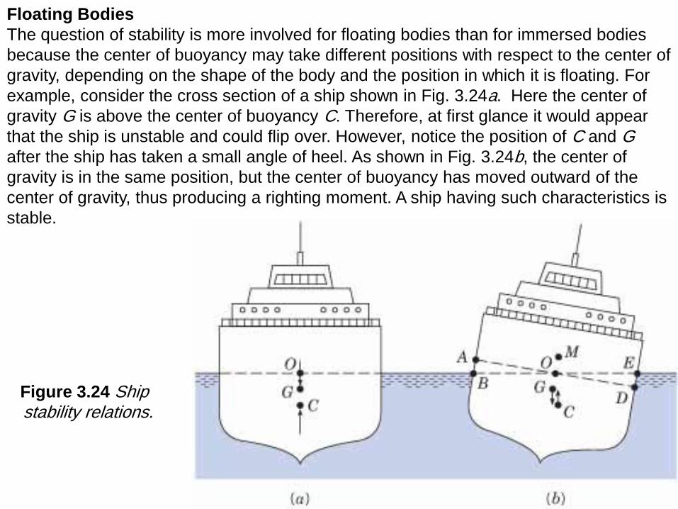
Figure 3.24 Ship stability relations.
Floating Bodies
The question of stability is more involved for floating bodies than for immersed bodies
because the center of buoyancy may take different positions with respect to the center of
gravity, depending on the shape of the body and the position in which it is floating. For
example, consider the cross section of a ship shown in Fig. 3.24a. Here the center of
gravity G is above the center of buoyancy C. Therefore, at first glance it would appear
that the ship is unstable and could flip over. However, notice the position of C and G after the ship has taken a small angle of heel. As shown in Fig. 3.24b, the center of
gravity is in the same position, but the center of buoyancy has moved outward of the
center of gravity, thus producing a righting moment. A ship having such characteristics is
stable.
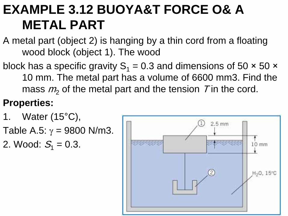
EXAMPLE 3.12 BUOYA&T FORCE O& A
METAL PART A metal part (object 2) is hanging by a thin cord from a floating
wood block (object 1). The wood
block has a specific gravity S1 = 0.3 and dimensions of 50 × 50 ×
10 mm. The metal part has a volume of 6600 mm3. Find the
mass m2 of the metal part and the tension T in the cord.
Properties:
1. Water (15°C),
Table A.5: g = 9800 N/m3.
2. Wood: S1 = 0.3.
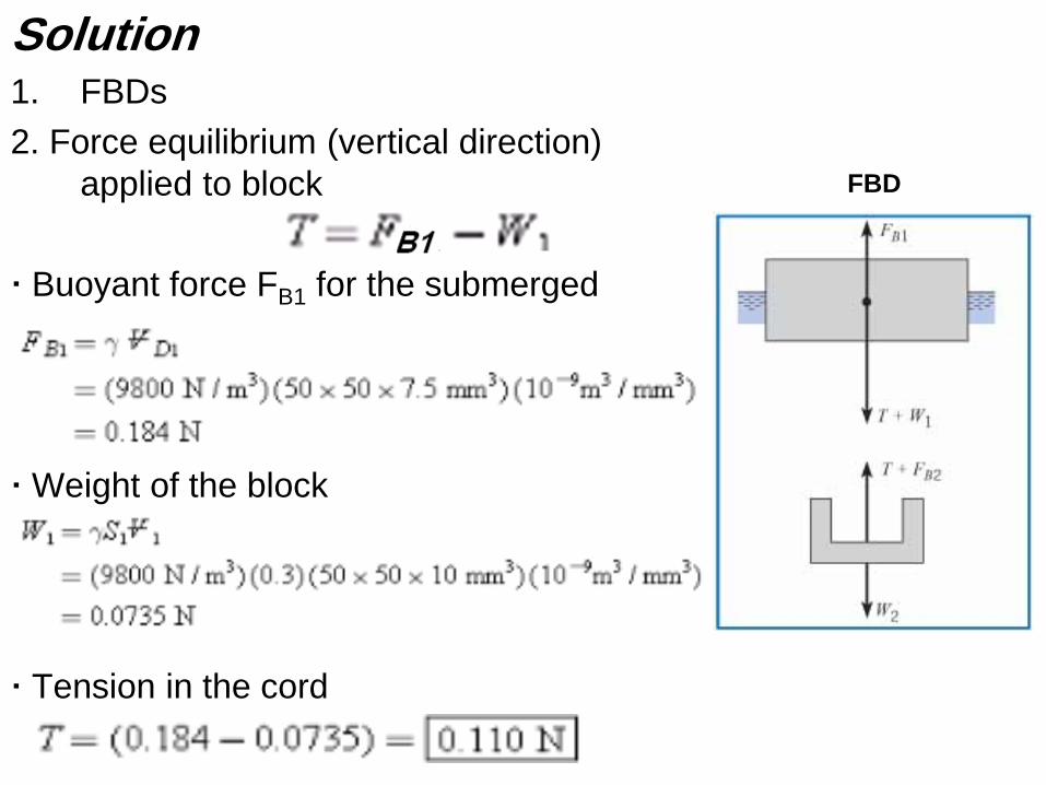
Solution 1. FBDs
2. Force equilibrium (vertical direction)
applied to block
· Buoyant force FB1 for the submerged
· Weight of the block
· Tension in the cord
FBD
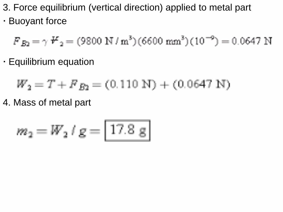
3. Force equilibrium (vertical direction) applied to metal part
· Buoyant force
· Equilibrium equation
4. Mass of metal part

Suggested Problems
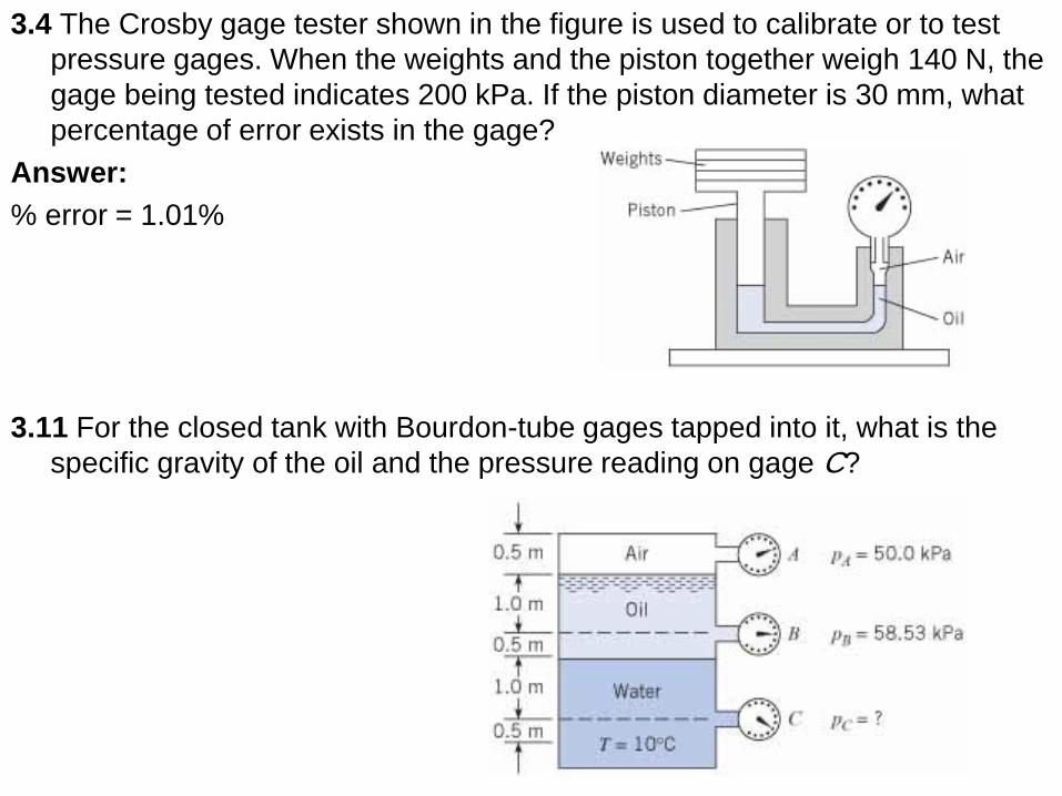
3.4 The Crosby gage tester shown in the figure is used to calibrate or to test
pressure gages. When the weights and the piston together weigh 140 N, the
gage being tested indicates 200 kPa. If the piston diameter is 30 mm, what
percentage of error exists in the gage?
Answer:
% error = 1.01%
3.11 For the closed tank with Bourdon-tube gages tapped into it, what is the
specific gravity of the oil and the pressure reading on gage C?
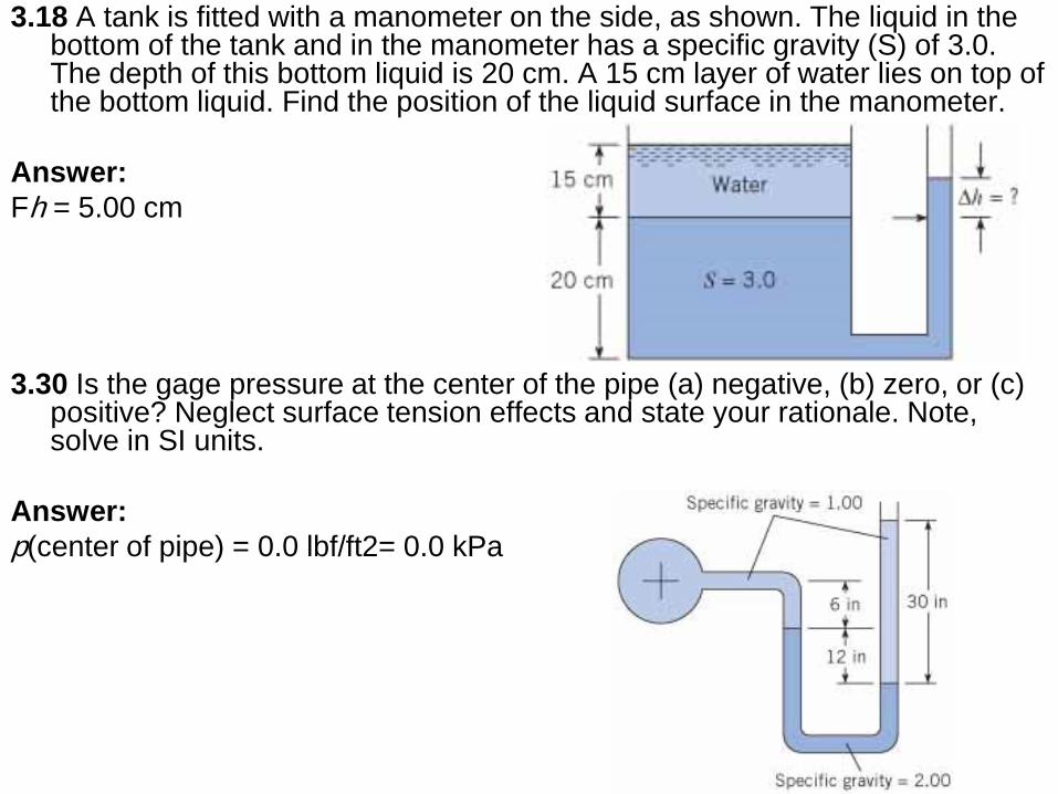
3.18 A tank is fitted with a manometer on the side, as shown. The liquid in the bottom of the tank and in the manometer has a specific gravity (S) of 3.0. The depth of this bottom liquid is 20 cm. A 15 cm layer of water lies on top of the bottom liquid. Find the position of the liquid surface in the manometer.
Answer:
Fh = 5.00 cm
3.30 Is the gage pressure at the center of the pipe (a) negative, (b) zero, or (c) positive? Neglect surface tension effects and state your rationale. Note, solve in SI units.
Answer:
p(center of pipe) = 0.0 lbf/ft2= 0.0 kPa
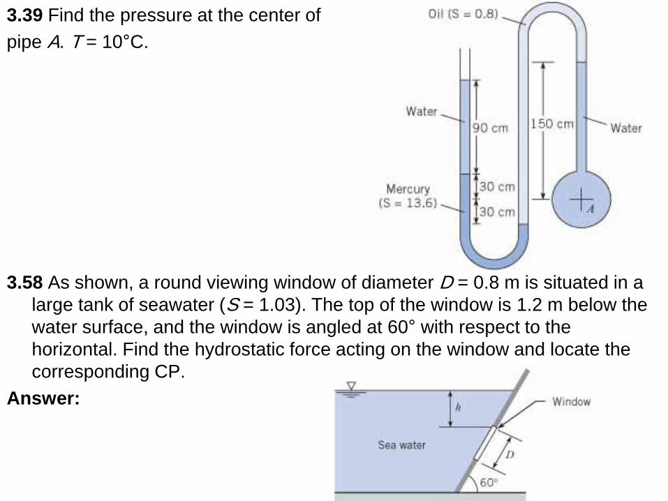
3.39 Find the pressure at the center of
pipe A. T = 10°C.
3.58 As shown, a round viewing window of diameter D = 0.8 m is situated in a
large tank of seawater (S = 1.03). The top of the window is 1.2 m below the
water surface, and the window is angled at 60° with respect to the
horizontal. Find the hydrostatic force acting on the window and locate the
corresponding CP.
Answer:
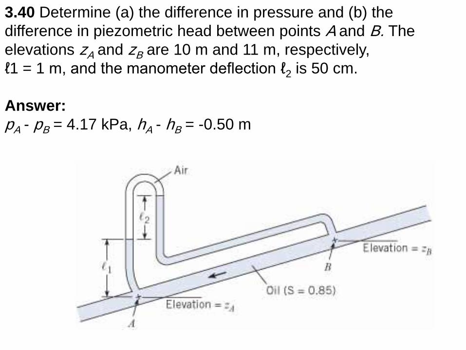
3.40 Determine (a) the difference in pressure and (b) the
difference in piezometric head between points A and B. The
elevations zA and zB are 10 m and 11 m, respectively,
ℓ1 = 1 m, and the manometer deflection ℓ2 is 50 cm.
Answer:
pA - pB = 4.17 kPa, hA - hB = -0.50 m
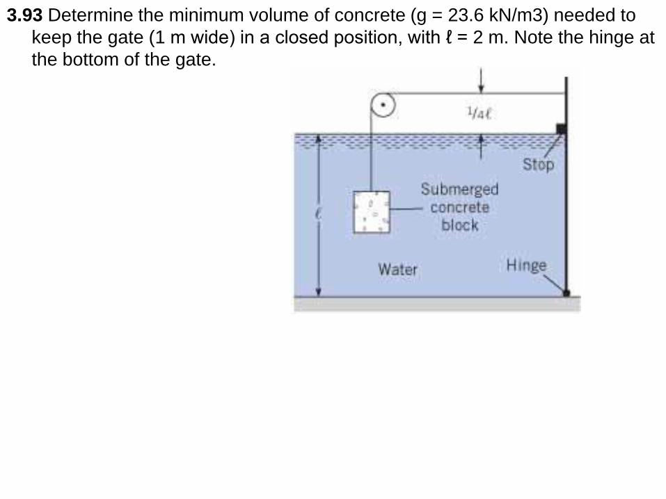
3.93 Determine the minimum volume of concrete (g = 23.6 kN/m3) needed to
keep the gate (1 m wide) in a closed position, with ℓ = 2 m. Note the hinge at
the bottom of the gate.