
Fluid Mechanics Lab Manual
81
Fluid Mechanics & Machinery Lab III SEMESTER
-
Upload
shan-mugam -
Category
Documents
-
view
142 -
download
0
Transcript of Fluid Mechanics Lab Manual
Fluid Mechanics & Machinery LabIII SEMESTER

CONTENTS
S.NO. DESCRIPTIONPAGE
NO.
1 STUDY OF FLOW METERS 01
2STUDY OF HYDRAULIC PUMPS
03
3 STUDY OF TURBINES 07
4 FLOW THROUGH PIPES—ORIFICEMETER 10
5 FLOW THROUGH PIPES—VENTURIMETER 13
6 CALIBRATION OF ROTA METER 16
7 FLOW THROUGH PIPES – MAJOR LOSSES 18
8 PERFORMANCE TEST ON A SINGLE STAGE CENTRIFUGAL PUMP 21
9 PERFORMANCE TEST ON A SUBMERSIBLE PUMP 24
10PERFORMANCE TEST ON A DOUBLE ACTING RECIPROCATING PUMP 27
11 PERFORMANCE TEST ON A GEAR OIL PUMP 31
12 PERFORMANCE TEST ON PELTON WHEEL TURBINE 34
13 PERFORMANCE TEST ON FRANCIS TURBINE 38
14 PERFORMANCE TEST ON KAPLAN TURBINE 41
15 VIVA (SAMPLE QUESTIONS) 44

SYLLABUS
FLUID MECHANICS AND MACHINERY LAB 0 0 3 2 (Common to Mechanical & Production)
LIST OF EXPERIMENTS
1. Determination of the Coefficient of discharge of given Orifice meter.
2. Determination of the Coefficient of discharge of given Venturi meter.
3. Calculation of the rate of flow using Rota meter.
4. Determination of friction factor for a given set of pipes.
5. Conducting experiments and drawing the characteristic curves of centrifugal pump/
submergible pump
6. Conducting experiments and drawing the characteristic curves of reciprocating pump.
7. Conducting experiments and drawing the characteristic curves of Gear pump.
8. Conducting experiments and drawing the characteristic curves of Pelton wheel.
9. Conducting experiments and drawing the characteristics curves of Francis turbine.
10. Conducting experiments and drawing the characteristic curves of Kaplan turbine.
LIST OF EQUIPMENT
(For a batch of 30 students)1. Orifice meter setup
2. Venturi meter setup
3. Rota meter setup
4. Pipe Flow analysis setup
5. Centrifugal pump/submergible pump setup
6. Reciprocating pump setup
7. Gear pump setup
8. Pelton wheel setup
9. Francis turbine setup
10. Kaplan turbine setup

FLUID MECHANICS
It deals behavior of fluids under rest as well as in motion.
Fluid is a substance, which is capable of flowing (both gases and liquids).
SIGNIFICANCE OF FLUID MECHANICS
Fluid mechanics encompassed a great many fascinating areas like,
Design of wide range of hydraulic structures (dams, canals, weirs etc) and machinery
(pumps& turbines)
Design of a complex network of pumping and pipelines for transporting liquids; flow of
water through pipes and its distribution to domestic service lines.
Fluidic control devices: both pneumatic & hydraulic.
Power generation from conventional methods such as hydroelectric, Steam and gas
turbine, to newer ones involving magneto fluid dynamics.
Methods and devices or the measurement of various fluids at rest or in motion.
Study of man’s environment in subject like oceanography and geology.
Human circulatory system, ie, flow of blood in veins and the pumping action of the heart.
BUOYANCY
BUOY means- lift, buoyancy force means- lifting force
Fluid experience an upward thrust due to fluid pressure –force is called buoyancy force.
ARCHIMEDES PRINCIPLE.
A body immersed in a fluid is buoyed / lifted up by a force equal to the weight of the
fluid displaced by the body .The body apparently losses as much of its weight of the fluid
displaced by it a floating body displaced the volume of fluid just sufficient to balance its weight
BERNOULLI’S EQUATION
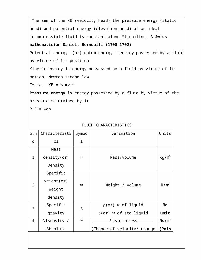
The sum of the KE (velocity head) the pressure energy (static head) and potential energy
(elevation head) of an ideal incompressible fluid is constant along Streamline. A Swiss
mathematician Daniel, Bernoulli (1700-1702)
Potential energy (or) datum energy – energy possessed by a fluid by virtue of its position
Kinetic energy is energy possessed by a fluid by virtue of its motion. Newton second law
F= ma. KE = ½ mv 2
Pressure energy is energy possessed by a fluid by virtue of the pressure maintained by it
P.E = wgh

FLUID CHARACTERISTICS
S.no Characteristics Symbol Definition Units
1Mass density(or)
Density Mass/volume Kg/m3
2Specific weight(or)
Weight densityw Weight / volume N/m3
3 Specific gravity S(or) w of liquid
(or) w of std.liquidNo unit
4
Viscosity /
Absolute viscosity /
Dynamic viscosity
Shear stress
(Change of velocity/ change of distance)Ns/m2
(Poise)
5 Kinematic viscosity = / m2/s
(Stoke)
Note:
VISCOSITY:
It is the property of the fluid, which offers resistance to flow.
It is a measure of internal fluid friction, which causes resistance to flow.
It’s due to cohesion and molecular momentum exchange between fluid layers.
MEASUREMENT
SPECIFIC GRAVITY
- Pygronometer
- Hydrometer (density measurement)
VISCOSITY
- Capillary tube viscometer
- Efflux (say bolt, redwood)
- Falling sphere viscometer
- Rotating cylinder viscometer,
VELOCITY
- Pitot tube
- Hot wire anemometer
- Cup & vane anemometer
- Current and turbine meters.
SOME BASIC UNIT CONVERSIONS
1. To convert kg in to N
1kg = 9.81 N 10 N
W = m gKg x m/s2 = 1N
2. Absolute Viscosity
1 Poise = dyne.sec/cm2
= 1/10 Ns/m2
1 Centi poise = 1/100 poise = 1x 10⁻³ Ns/m2
3.Kinematic viscosity
1 stoke = cm2 /sec =(1/100) 2 m2/ sec = 1x 10⁻⁴ m2/ sec
4.Standard atmospheric pressure.
1 atm = 760 mm of Hg = 1.033 kg/cm2
= 10.33 m of water
Vacuum Pressure in to Vacuum head
760 mm of Hg = 10.33 m of water1mm of Hg = 10.33/ 760 mwc (meter of water column)
5. Pressure in to pressure head
If P is in(N/m 2 ) If P is in kg/cm 2 P = w (or) x H H = P/w H = P/w kg/cm2 / N/m3
= N/m2 / N/m3 = 9.81x 10⁴ N/m2
= m 9.81x 10³ N/m3
= 10 mNote: 1 kg/cm2 = 1 bar
1 kg/cm2 = (1x10) N (1kg = 10N, 1 cm2 = 10-4m2) (10-4) m2
= 1x10⁵ N/m2 = 1bar

STUDY OF FLOW METERS
Flow meter is device used to measure the discharge of any liquid flowing through a
Pipeline,tank, Reservoir, Open Channel etc...
1. Orifices & mouthpieces – from a tank /reservoir
2. Weir & notch –open channel
3. Venturi, orifice plates, nozzles – pipelines
4. Rotameter, elbow meters
5. Electro magnetic flow meters - non contact type
6. Ultra sonic flow meter
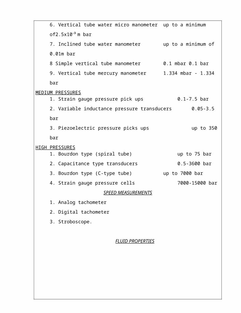
PRESSURE MEASURING DEVICES AND THEIR RANGESLOW PRESSURES
1. Pirani gauges 10-5-1.3 m bar
2. Mcleod gauges 10-4-0.1 m bar
3. Diaphragm gauges up to a minimum of 10-3 m bar
4. Low-pressure bourdon gauges up to a minimum of 10 m bar
5. Inclined tube water micro manometers up to a minimum of 5x10⁻⁴ m bar
6. Vertical tube water micro manometer up to a minimum of2.5x10-3 m bar
7. Inclined tube water manometer up to a minimum of 0.01m bar
8 Simple vertical tube manometer 0.1 mbar 0.1 bar
9. Vertical tube mercury manometer 1.334 mbar - 1.334 bar
MEDIUM PRESSURES1. Strain gauge pressure pick ups 0.1-7.5 bar
2. Variable inductance pressure transducers 0.05-3.5 bar
3. Piezoelectric pressure picks ups up to 350 bar
HIGH PRESSURES1. Bourdon type (spiral tube) up to 75 bar
2. Capacitance type transducers 0.5-3600 bar
3. Bourdon type (C-type tube) up to 7000 bar
4. Strain gauge pressure cells 7000-15000 bar
SPEED MEASUREMENTS
1. Analog tachometer
2. Digital tachometer
3. Stroboscope.

FLUID PROPERTIES
COMPARISION OF FLOW METERS

STUDY OF HYDRAULIC PUMPS
PUMPSPump is a device used for lifting liquids from a lower level to higher level. It converts mechanical energy into hydraulic energy.
CLASSIFICATION.:
1. Positive displacement pumps.(Reciprocating pumps, gear pumps) 2 .Non Positive displacement pumps. or ( centrifugal pumps)
A positive displacement pump increases the fluid pressure while a Non positive pump
only transfers only the fluid.
RECIPROCATING PUMPS
Working principle: -Movement of the piston or plunger creates a vacuum and atmospheric pressure
force the water up through the suction pipe into the cylinder.Reciprocating pumps are generally operates at low speeds and is therefore to be
coupled to an electric motor with v-belts.
Application The reciprocating pump is best suited for relatively small capacities and high
heads. In oil drilling operations, this type of pump is very common.
Pneumatic pressure system, feeding small boiler condensate returns and light oil pumping.
DOUBLE ACTING RECIPROCATING PUMP
The pump is said to be a double acting when the liquid pressure acts on both sides of the piston or plunger. When the crank rotates, the piston or plunger reciprocates inside the cylinder.Therefore, when the piston moves from left to right suction is taking place on the left side of the piston, while the delivery on the right side. Similarly, when the piston moves from right to left vice versa action takes place.
Thus, the discharge of double acting pump is continuous. AIR VESSEL:
Air vessel is a closed chamber fitted on the suction as well as on the delivery side, near the pump cylinder to reduce the accelerating heads. It acts like an intermediate reservoir.Air vessels are fitted with suction and delivery pipes to reduce the acceleration head.
FUNCTIONS:
Suction Side: Reduces the possibility of separation. Pump can be run at higher speed. Length of the suction pipe below the air vessel can be increased.
Delivery Side: A large amount of power consumed in supplying accelerating head can be shared. Constant rate of discharge can be ensured.
CENTRIFUGAL PUMPS
A pump, which lifts the liquid from lower to higher level by means of centrifugal force, called as centrifugal pump.
Main parts- Spiral casing made of cast iron having suction and delivery arrangement Impeller having backward curved vanes keyed to the shaft
WORKING PRINCIPLE: A centrifugal pump works on the principle that when a certain mass of fluid is rotated by an external source, it is thrown away from the central axis of rotation and a centrifugal head is impressed, which enables it to rise to a higher level.Priming
Before starting the centrifugal pump, to remove any air, gas or vapour from casing, suction pipe of the pump is called priming.
If a pump is not primed before starting, air pockets inside the impeller may give to vortices and cause-- discontinuity of flow.
Further dry running of the pump may result in rubbing and seizing of the Wearing rings and cause serious damage.
CLASSIFICATON OF CENTRIFUGAL PUMP:
Based on working head: - Low head pumps: head up to 15m Medium head pumps: head between 15 to 40m High head pumps: head above 40m
Based on type of casing: - Volute casing pump Vortex casing pump Turbine pump or diffusion pump
Base on direction of flow:- Radial flow Axial flow Mixed flow

Based on number of impeller shafts:- Single stage pump Multi stage pump
Based on the position of shaft:- Horizontal pump Vertical pump
FUNCTION OF CASING:To convert the kinetic energy of the liquid flowing through the casing into pressure
energy
PRIMING:-Removal of air present in the casing, impeller and suction pipe by filling in the pump
with liquid is known as priming.
IMPELLER :-Closed impeller used for handling non viscous pure liquid such as water oil, chemicals
and acids. Semi open impeller used for handling viscous liquids .Open impeller used for handling liquids having coarse debris as in sewage disposal, mud
and clay.EFFICIENCIES OF CENTRIFUGAL PUMP:
Manometric efficiency O/p of pump
Work done by the impeller
Mechanical efficiencyWork done by the impellerWork supplied by the motor
Over all efficiencyOut put of the pumpWork supplied by the motor
SUBMERSIBLE PUMP (or) DEEP WELL PUMP The pump is connected to a electric motor. The pump together with electric motor operates below the liquid surface,
-A pump used for pumping liquids from deep wells is known as deep well pump.-Turbine pumps are extensively used for deep well pumping -these pumps are generally multistage pumps with vertical shafts.-these are capable of pumping water against heads up to 350 m and capacities up to 550lps.-Working as that of multistage c/f pumps-It finds it application in irrigation as well as other deep well sources.

JET PUMP
It is a combination of centrifugal pump and an ejector, which is commonly referred to as the jet. A jet pimp consists of a conventional radial flow C/F pump with a jet nozzle at the suction end. It helps to increase the suction lift beyond the normal limit 6 to 8 m of water head. With the use of jet assembly it is possible to increase the suction lift up to 60m.
WORKING PRINCIPLE: A stream of high-pressure water from the delivery pipe of the pump is allowed to flow through the suction jet nozzle. The pressure energy is converted in to kinetic energy due to which local pressure drop takes place. Due to this a partial vacuum is created and water is sucked from the well. APPLICATIONS:
1. It can be used to take the muddy water from the excavation trenches.2. To lift the water from wells of smaller bores.3. Employed for mining and for pumping oil.
Advantages: - Simple in design No lubrication problem No reciprocating parts
GEAR PUMP
Gear pump is a constant delivery positive displacement pump
CLASSIFICATON OF GEAR PUMP: External gear pump Internal gear pump
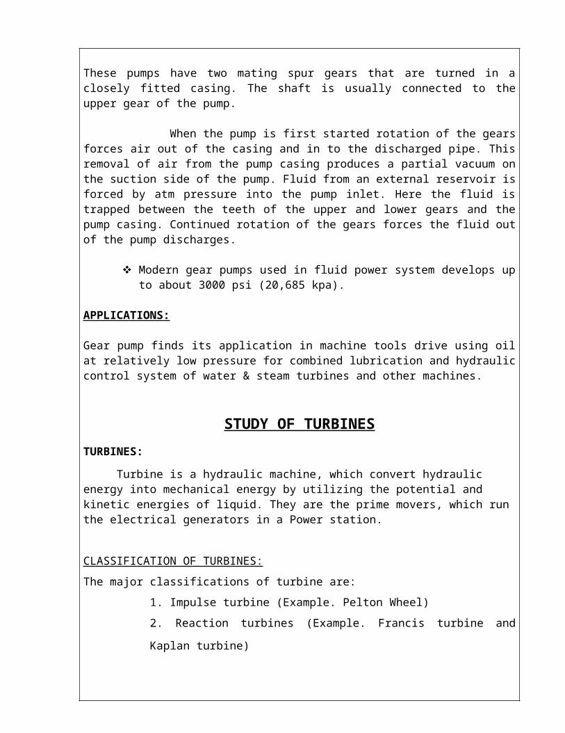
These pumps have two mating spur gears that are turned in a closely fitted casing. The shaft is usually connected to the upper gear of the pump.
When the pump is first started rotation of the gears forces air out of the casing and in to the discharged pipe. This removal of air from the pump casing produces a partial vacuum on the suction side of the pump. Fluid from an external reservoir is forced by atm pressure into the pump inlet. Here the fluid is trapped between the teeth of the upper and lower gears and the pump casing. Continued rotation of the gears forces the fluid out of the pump discharges.
Modern gear pumps used in fluid power system develops up to about 3000 psi (20,685 kpa).
APPLICATIONS :
Gear pump finds its application in machine tools drive using oil at relatively low pressure for combined lubrication and hydraulic control system of water & steam turbines and other machines.

STUDY OF TURBINES
TURBINES:
Turbine is a hydraulic machine, which convert hydraulic energy into mechanical energy by utilizing the potential and kinetic energies of liquid. They are the prime movers, which run the electrical generators in a Power station.
CLASSIFICATION OF TURBINES:
The major classifications of turbine are:
1. Impulse turbine (Example. Pelton Wheel)
2. Reaction turbines (Example. Francis turbine and Kaplan turbine)
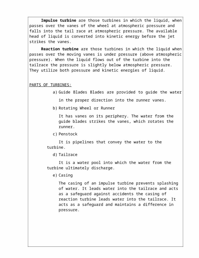
Impulse turbine are those turbines in which the liquid, when passes over the vanes of the wheel at atmospheric pressure and falls into the tail race at atmospheric pressure. The available head of liquid is converted into kinetic energy before the jet strikes the vanes.
Reaction turbine are those turbines in which the liquid when passes over the moving vanes is under pressure (above atmospheric pressure). When the liquid flows out of the turbine into the tailrace the pressure is slightly below atmospheric pressure. They utilize both pressure and kinetic energies of liquid.
PARTS OF TURBINES:
a) Guide Blades Blades are provided to guide the water in the proper direction
into the runner vanes.
b) Rotating Wheel or Runner
It has vanes on its periphery. The water from the guide blades strikes the vanes, which rotates the runner.
c) Penstock
It is pipelines that convey the water to the turbine.
d) Tailrace
It is a water pool into which the water from the turbine ultimately discharge.
e) Casing
The casing of an impulse turbine prevents splashing of water. It leads water into the tailrace and acts as a safeguard against accidents the casing of reaction turbine leads water into the tailrace. It acts as a safeguard and maintains a difference in pressure.

1. PELTON WHEEL :
It is named after its inventor, L.A.Peltion, an American Engineer. It is used for high heads of water. The flow of water is tangential to the wheel.
The runner of the pelton wheel turbine has a number of hemispherical twin cups called buckets, with a dividing wall called splitter. The jet of water imp rings on the bucket with a high velocity it after flowing over the vanes leaves with a low velocity. The pressure of water is atmospheric. The splitter splits the jet into two parts and it glides over the buckets. After performing work on the buckets, water is discharged into the tail race.
In General, Pelton turbines have only a single jet. When a single jet could not develop the required power more number of jets may be provided by evenly spacing them around the same runner.
2. FRANCIS TURBINE:
It is named after its designer. James Francis, English engineer. It is an inward mixed flow reaction turbine under medium head with medium discharge. The jet of water enters radially at the outer periphery and leaves axially at the centre. The turbine consists of stationary guide blades, which guide the water to enter the wheel at the correct angle without shock. The guide blades can be rotated around a pivot at each of its centre. The runner consists of two annular plates placed parallel with a number of vanes. In this turbine, the pressure at the inlet is more than that at the outlet. After doing the work, water is discharged to the tailrace through a closed tube called draft tube.
3. KAPLAN TURBINE:
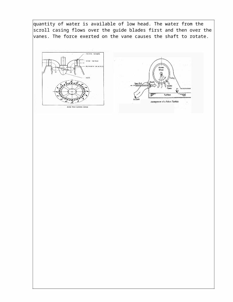
It is named after its inventor, Dr.Victor Kaplan, a Germart Scientist. It is a low head, high discharged reaction turbine with axial flow. The runner resembles the propeller of a ship. Hence it is also called an improved propeller turbine. The flow of water is parallel to the shaft. It is very ideal when a large quantity of water is available of low head. The water from the scroll casing flows over the guide blades first and then over the vanes. The force exerted on the vane causes the shaft to rotate.

15

Ex. No: 01Date: FLOW THROUGH PIPES—ORIFICEMETER
AIM:
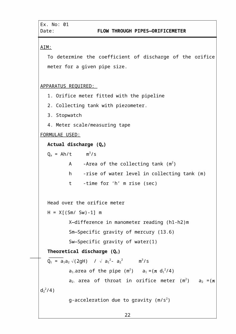
To determine the coefficient of discharge of the orifice meter for a given pipe size.
APPARATUS REQUIRED:
1. Orifice meter fitted with the pipeline
2. Collecting tank with piezometer.
3. Stopwatch
4. Meter scale/measuring tape
FORMULAE USED:
Actual discharge (Qa)
Qa = Ah/t m3/s
A -Area of the collecting tank (m2)
h -rise of water level in collecting tank (m)
t -time for ‘h’ m rise (sec)
Head over the orifice meter
H = X[(Sm/ Sw)-1] m
X—difference in manometer reading (h1-h2)m
Sm—Specific gravity of mercury (13.6)
Sw—Specific gravity of water(1)
Theoretical discharge (Qt)
Qt = a1a2 Ö(2gH) / Ö a12- a2
2 m3/s
a1-area of the pipe (m2) a1 =( d12/4)
a2- area of throat in orifice meter (m2) a2 =( d22/4)
g-acceleration due to gravity (m/s2)
H-head over the orifice meter (m)
d1-diameter of the pipe (m)
d2-diameter of the orifice(m)
16
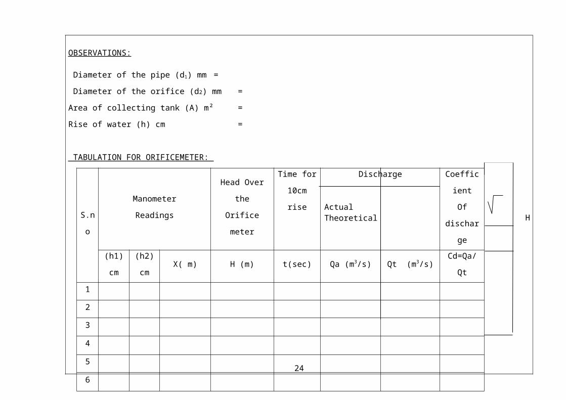
OBSERVATIONS:
Diameter of the pipe (d1) mm =
Diameter of the orifice (d2) mm =
Area of collecting tank (A) m² =
Rise of water (h) cm =
TABULATION FOR ORIFICEMETER:
H
S.no
Manometer
Readings
Head Over the
Orifice meter
Time for
10cm rise
Discharge
Actual Theoretical
Coefficient
Of
discharge
(h1)cm (h2)cm X( m) H (m) t(sec) Qa (m3/s) Qt (m3/s) Cd=Qa/Qt
1
2
3
4
5
6
17
PROCEDURE:
1. The diameter of the pipe and internal cross section area of collecting tank are noted
down.
2. Close all the cocks except manometer cocks.
3. Then open the corresponding cocks of a given pipe size.
4. Start the motor and adjust the gate valve at exit to maintain steady flow for desired
head.
5. Note the manometer readings and note the time for ‘h’ cm rise of water level in
collecting tank.
6. Repeat the above procedure for different manometer heads by adjusting the gate
valve.
GRAPH:
Head (ÖH) Vs Actual discharge (Qa)
RESULT:
The coefficient of discharge of an orifice meter for a given pipe size
1) From observation ---------
2) From graph---------
18

Ex. No: 02Date: FLOW THROUGH PIPES—VENTURIMETER
AIM:
To determine the coefficient of discharge of the venturimeter for a given pipe size
APPARATUS REQUIRED:
1. Venturimeter fitted with the pipeline
2. Collecting tank with piezometer
3. Stopwatch
4. Meter scale/measuring tape
FORMULAE USED:
Actual discharge (Qa)
Qa = Ah/t m3/s
A -Area of the collecting tank (m2)
h -rise if water level in collecting tank (m)
t -time for ‘h’ m rise (sec)
Head over the venturimeter
H = X[(Sm/ Sw)-1] m
X—difference in manometer reading (h1-h2)
Sm—Specific gravity of mercury (13.6)
Sw—Specific gravity of water (1).
Theoretical discharge (Qt)
Qt = a1a2 Ö(2gH) / Ö a12- a2
2 m3/s
a1- area of the pipe (m2) a1 = ( d12/4)
a2- area of throat in venturimeter (m2) a2 = ( d22/4)
g- acceleration due to gravity (m/s2)
H-head over the venturimeter (m)
d1- diameter of the pipe (m)
d2- diameter of the venturi (m)
19
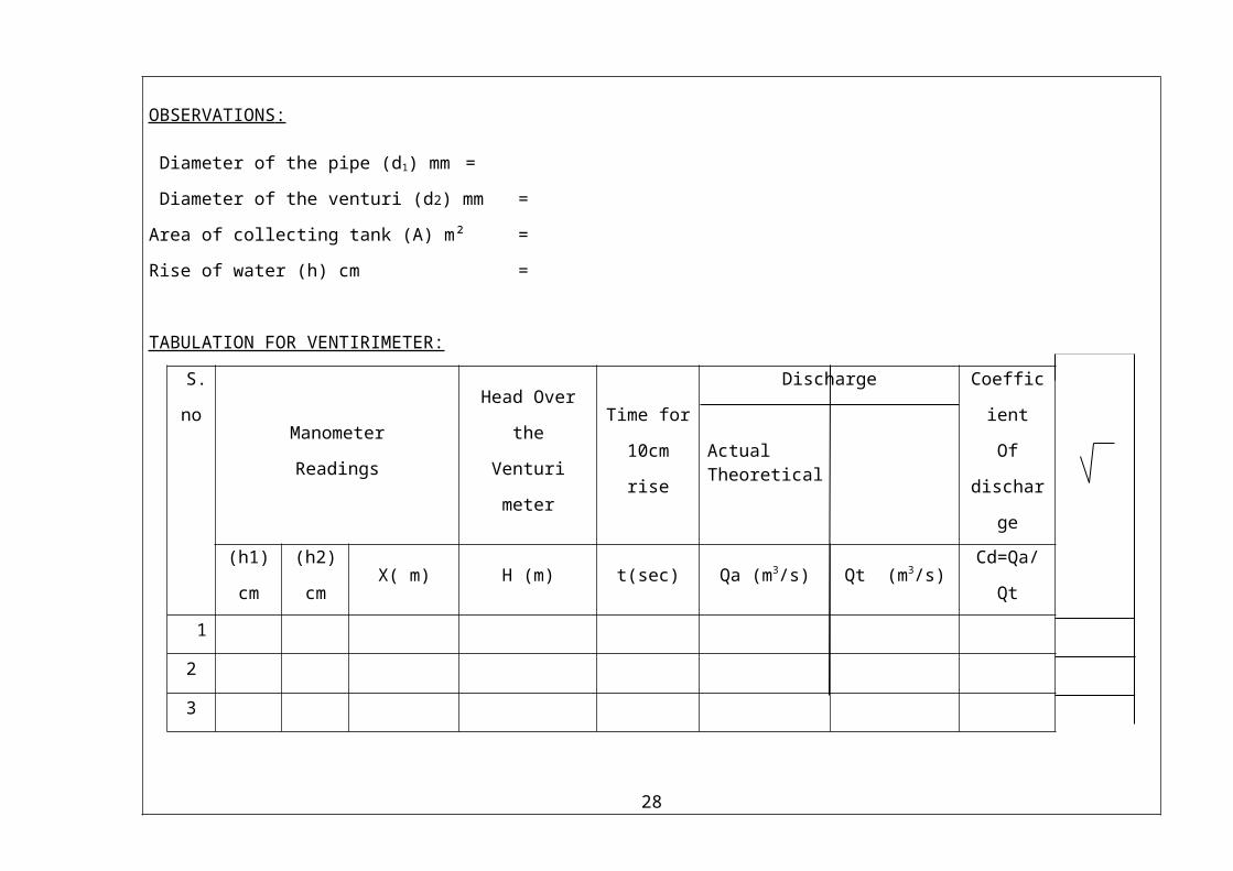
OBSERVATIONS :
Diameter of the pipe (d1) mm =
Diameter of the venturi (d2) mm =
Area of collecting tank (A) m² =
Rise of water (h) cm =
TABULATION FOR VENTIRIMETER:
S.n
oManometer
Readings
Head Over the
Venturi meter
Time for
10cm rise
Discharge
Actual Theoretical
Coefficient
Of
discharge
(h1)cm (h2)cm X( m) H (m) t(sec) Qa (m3/s) Qt (m3/s) Cd=Qa/Qt
1
2
3
4
5
6
20
PROCEDURE:
1. The diameter of the pipe and internal cross section area of collecting tank are noted
down
2. Close all the cocks except manometer cocks.
3. Then open the corresponding cocks of a given pipe size.
4. Start the motor and adjust the gate valve at exit to maintain steady flow for desired
head.
5. Note the manometer readings and note the time for ‘h’ cm rise of water level in
collecting tank.
6. Repeat the above procedure for different manometer heads by adjusting the gate
valve.
GRAPH:
Head (ÖH) Vs Actual discharge (Qa)
RESULT:
The coefficient of discharge of the venturimeter for a given pipe size
1) From observation ---------
2) From graph---------
21
Ex. No: 03Date: CALIBRATION OF ROTA METER
AIM:
To calibrate the given rota meter and to determine the percentage of error.
APPARATUS REQUIRED :
1. Collecting tank with piezometer
2. Rota meter fitted in pipeline
3. Stopwatch
4. Meterscale /measuring tape
FORMULAE USED :
Actual discharge
Qa= Ah/t m3/s
Where
A -Area of collecting tank
h -rise of water collecting tank (m)
t -time for ‘h’m rise of water (sec)
Theoretical discharge
Qt= (Rota meter reading)/ (1000x60x60) m3/s
Calibration error
Cerror =[ (Qt-Qa)/Qt ]x100
22

TABULATION FOR ROTAMETER:
S.noRota meter
reading (LPH)
Time for
‘h’cm rise of
water (t) sec
Actual
Discharge
(Qa) m3/s
Theoretical
Discharge
(Qt ) m3/s
Calibration of
Error (%)
[(Qt-Qa)/Qt ]
x100
1
2
3
4
5
6
OBSERVATION:
Area of collecting tank (A) m² =
Rise of water (h) cm =
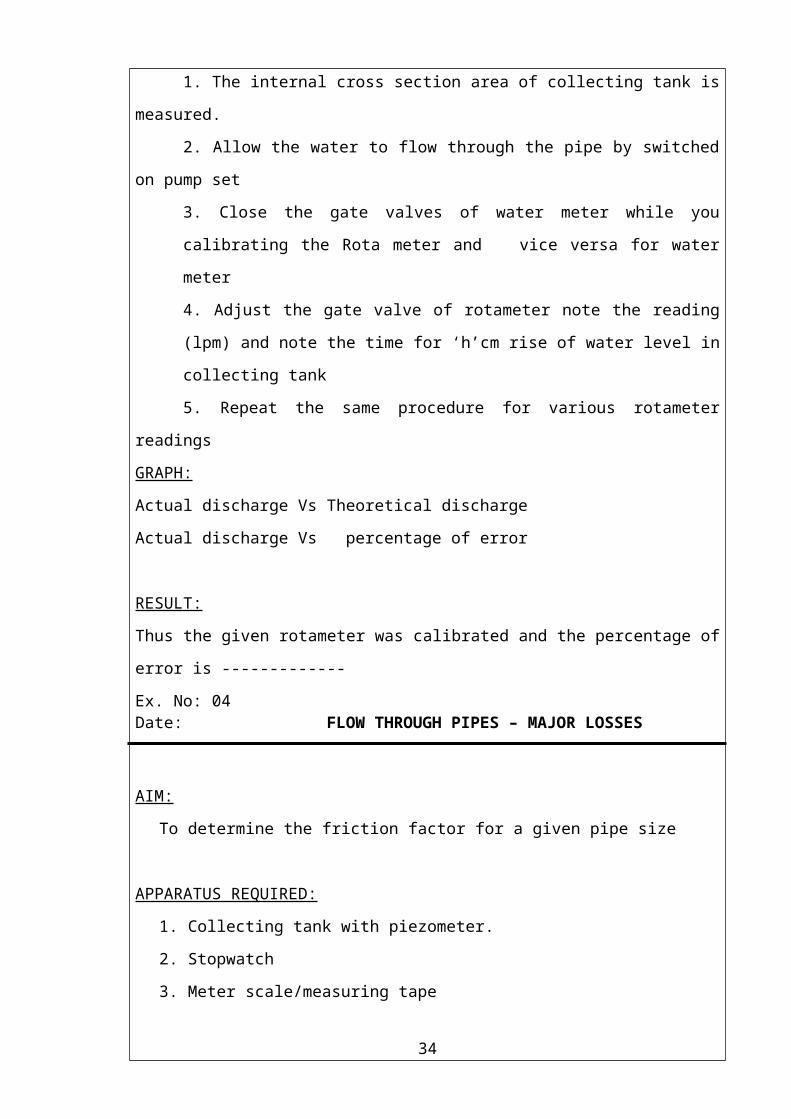
PROCEDURE :
1. The internal cross section area of collecting tank is measured.
2. Allow the water to flow through the pipe by switched on pump set
3. Close the gate valves of water meter while you calibrating the Rota meter and
vice versa for water meter
4. Adjust the gate valve of rotameter note the reading (lpm) and note the time for
‘h’cm rise of water level in collecting tank
5. Repeat the same procedure for various rotameter readings
GRAPH:
Actual discharge Vs Theoretical discharge
Actual discharge Vs percentage of error
RESULT:
Thus the given rotameter was calibrated and the percentage of error is -------------
23
Ex. No: 04Date: FLOW THROUGH PIPES – MAJOR LOSSES
AIM:
To determine the friction factor for a given pipe size
APPARATUS REQUIRED:
1. Collecting tank with piezometer.
2. Stopwatch
3. Meter scale/measuring tape
FORMULAE USED:
Actual discharge (Qa)
Qa = Ah/t m3/s
A -Area of the collecting tank(m2)
h -rise if water level in collecting tank (m)
t -time for ‘h’ m rise (sec)
Head loss due to friction (hf)
hf = X[(Sm/ Sw)-1] m
X -difference in manometer reading (h1-h2) m.
Sm -Specific gravity of mercury (13.6)
Sw -Specific gravity of water (1)
Darcy’s friction factor (f)
hf = flv2 / 2gd
f = hf.2.g.d / l v2
d -diameter of pipe (m)
l -length of the pipe (m)
v -velocity of the liquid (m/s) v=Qa/a
g -acceleration due to gravity (m/s2)
a -area of the pipe (m2) a = ( d2)/4
Reynolds number (Re)
Re = (vd)/V -velocity of the water (m/s)d -diameter of he pipe (m) -kinematic viscosity of water (m2/s) (1.002x10 – 6)
24

OBSERVATION:
Length of the pipe (l) -----------m
Diameter of the pipe (d) --------m
Area of collecting tank (A) -----m2
TABULATION FOR MAJOR LOSS :
S.no Manometer
Readings
h1 cm h2 cm x m
Head
loss
hf (m)
Time for 10 cm
rise of water (t)
sec
Discharge
Q (m3/s)
Velocity
V (m/s) V2
Friction
Factor‘f ’
Reynolds
Number
Re = (vd)/
1
2
3
4
5
6
25

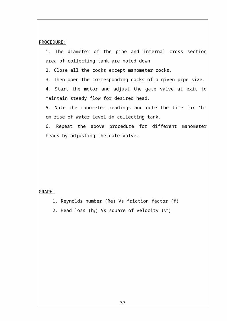
PROCEDURE:
1. The diameter of the pipe and internal cross section area of collecting tank are noted
down
2. Close all the cocks except manometer cocks.
3. Then open the corresponding cocks of a given pipe size.
4. Start the motor and adjust the gate valve at exit to maintain steady flow for desired
head.
5. Note the manometer readings and note the time for ‘h’ cm rise of water level in
collecting tank.
6. Repeat the above procedure for different manometer heads by adjusting the gate
valve.
GRAPH:
1. Reynolds number (Re) Vs friction factor (f)
2. Head loss (hf) Vs square of velocity (v2)
RESULT:
Friction factor for a given pipe size---------
26

Ex. No: 05Date: PERFORMANCE TEST ON A SINGLE STAGE CENTRIFUGAL PUMP
AIM:To conduct and study the performance 2.H.P.three phase single stage centrifugal pump.
TEST BED REQUIREMENTS:1. Bourdon type vacuum gauge for measuring the suction pressure.2. Bourdon type pressure gauge for measuring the delivery pressure.3. Three phase energy meter for measuring input power.4. Collecting tank of known cross section with piezometer and stop watch to measure the flow rate.5. Measuring tape or scale to find the difference in height of pressure and vaccum gauges.
DESCRIPITION:
Centrifugal pump is a device, which raises the liquid from lower level to higher level by the action of centrifugal force.Components:1) Impeller: Impeller is a rotating element (Rotor) with a series of backward curved blades (vanes). It is mounted on a shaft usually coupled with an electric motor. 2) Casing: It is an airtight chamber surrounding the pump impeller it contains a suction and delivery arrangements3) Suction pipe: The pipe which connects the center / eye of the impeller to the sump from which liquid is to be lifted.4) Delivery pipe: The pipe, which is connected at the outlet of the pump and it, delivers the liquid to required height.5) Foot valve: It acting as a non-return valve. It allows the water to raise in one direction only.6) Strainer: It prevents the entry of mud, sediments and other foreign particles in to the suction pipe.
FORMULAE USED :
1. Discharge (Q)
Q= Ah/t m3/sA -internal cross sectional area of collecting tank (m2)h -rise of water oil level in collecting tank (m)t -time taken for h-m rise. (Sec)
2. Total head (H)
H = Hs + Hd + X mwc
Hs - Vacuum (suction) head =(Vx10.33)/760Hd -pressure (delivery) head = (Px10)X -difference in level of pressure & vacuum gauges.
27
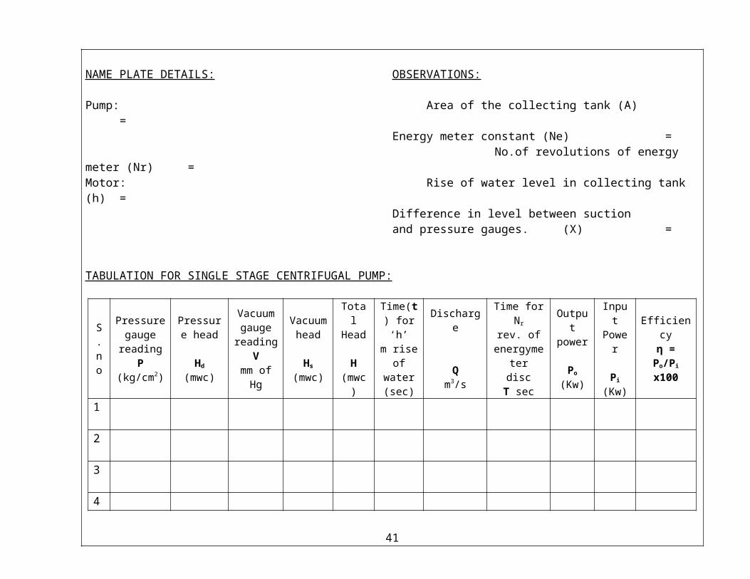
NAME PLATE DETAILS: OBSERVATIONS:
Pump: Area of the collecting tank (A) =Energy meter constant (Ne) =
No.of revolutions of energy meter (Nr) =Motor: Rise of water level in collecting tank (h) =
Difference in level between suctionand pressure gauges. (X) =
TABULATION FOR SINGLE STAGE CENTRIFUGAL PUMP:
S.no
Pressure gauge
readingP
(kg/cm2)
Pressure head
Hd
(mwc)
Vacuum gauge
readingV
mm of Hg
Vacuum head
Hs
(mwc)
TotalHead
H(mwc)
Time(t) for ‘h’
m rise of water(sec)
Discharge
Qm3/s
Time forNr rev. of
energymeterdisc
T sec
Output power
Po
(Kw)
InputPower
Pi
(Kw)
Efficiencyη = Po/Pi
x100
1
2
3
4
5
6
28
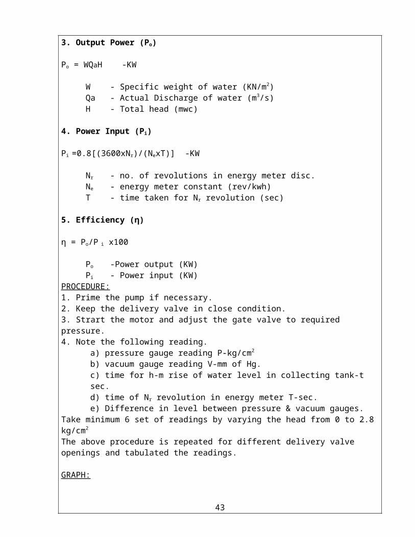
3. Output Power (Po)
Po = WQaH -KW
W - Specific weight of water (KN/m2) Qa - Actual Discharge of water (m3/s)H - Total head (mwc)
4. Power Input (Pi)
Pi =0.8[(3600xNr)/(NexT)] -KW
Nr - no. of revolutions in energy meter disc.Ne - energy meter constant (rev/kwh)T - time taken for Nr revolution (sec)
5. Efficiency (η)
η = Po/P i x100
Po -Power output (KW)Pi - Power input (KW)
PROCEDURE:1. Prime the pump if necessary.2. Keep the delivery valve in close condition.3. Strart the motor and adjust the gate valve to required pressure.4. Note the following reading.
a) pressure gauge reading P-kg/cm2
b) vacuum gauge reading V-mm of Hg.c) time for h-m rise of water level in collecting tank-t sec.d) time of Nr revolution in energy meter T-sec.e) Difference in level between pressure & vacuum gauges.
Take minimum 6 set of readings by varying the head from 0 to 2.8 kg/cm2
The above procedure is repeated for different delivery valve openings and tabulated the readings.
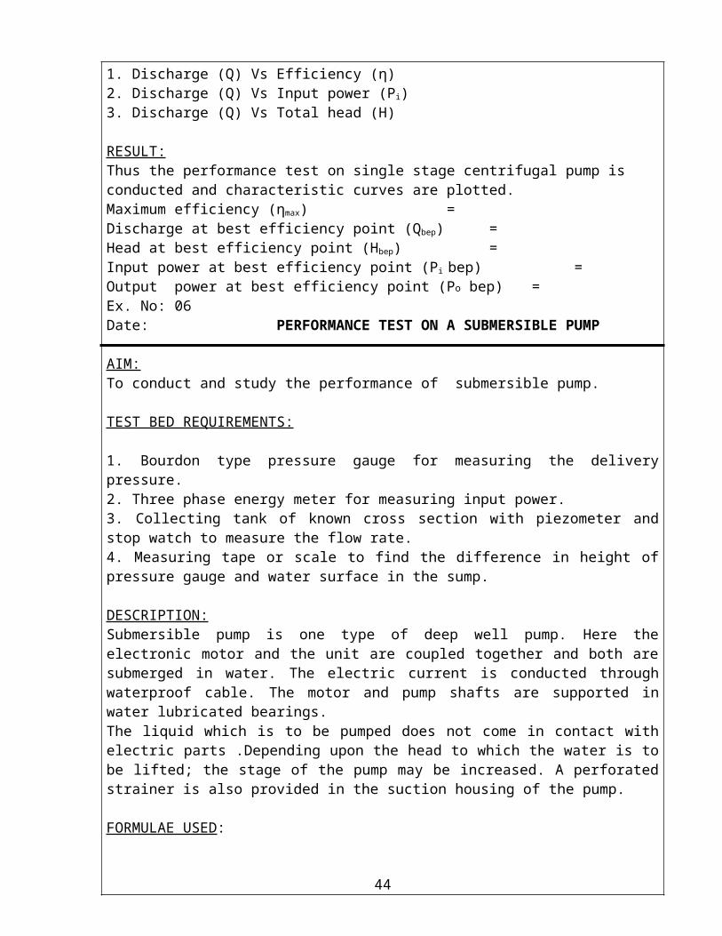
GRAPH:1. Discharge (Q) Vs Efficiency (η)2. Discharge (Q) Vs Input power (Pi)3. Discharge (Q) Vs Total head (H)
RESULT:Thus the performance test on single stage centrifugal pump is conducted and characteristic curves are plotted.Maximum efficiency (ηmax) =Discharge at best efficiency point (Qbep) =Head at best efficiency point (Hbep) =Input power at best efficiency point (Pi bep) =Output power at best efficiency point (Po bep) =
29

Ex. No: 06Date: PERFORMANCE TEST ON A SUBMERSIBLE PUMP
AIM:To conduct and study the performance of submersible pump.
TEST BED REQUIREMENTS:
1. Bourdon type pressure gauge for measuring the delivery pressure.2. Three phase energy meter for measuring input power.3. Collecting tank of known cross section with piezometer and stop watch to measure the flow rate.4. Measuring tape or scale to find the difference in height of pressure gauge and water surface in the sump.
DESCRIPTION:Submersible pump is one type of deep well pump. Here the electronic motor and the unit are coupled together and both are submerged in water. The electric current is conducted through waterproof cable. The motor and pump shafts are supported in water lubricated bearings.The liquid which is to be pumped does not come in contact with electric parts .Depending upon the head to which the water is to be lifted; the stage of the pump may be increased. A perforated strainer is also provided in the suction housing of the pump.
FORMULAE USED:
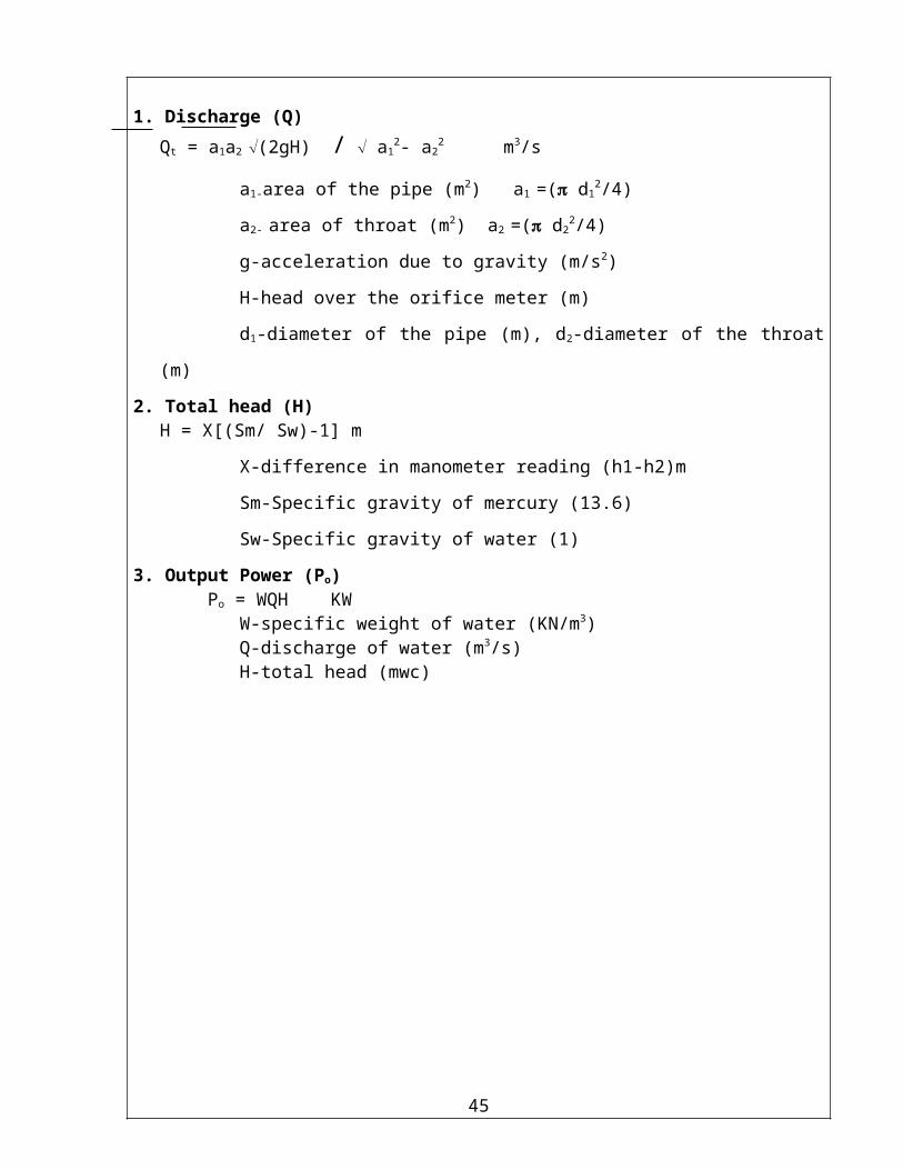
1. Discharge (Q)
Qt = a1a2 Ö(2gH) / Ö a12- a2
2 m3/s
a1-area of the pipe (m2) a1 =( d12/4)
a2- area of throat (m2) a2 =( d22/4)
g-acceleration due to gravity (m/s2)
H-head over the orifice meter (m)
d1-diameter of the pipe (m), d2-diameter of the throat (m)
2. Total head (H)H = X[(Sm/ Sw)-1] m
X-difference in manometer reading (h1-h2)m
Sm-Specific gravity of mercury (13.6)
Sw-Specific gravity of water (1)
3. Output Power (Po) Po = WQH KW
W-specific weight of water (KN/m3) Q-discharge of water (m3/s)H-total head (mwc)
30
NAME PLATE DETAILS: OBSERVATIONS:
Pump: Area of the collecting tank(A) =Energy meter constant (Ne) =
No. of revolutions of energy meter (Nr) =Motor: Diameter of the pipe(d1) =
Diameter of the throat(d2) =Difference in level of water and pressure gauge (Z) =
TABULATION FOR SUBMERSIBLE PUMP:
S.No
Pressure gauge reading
P(kg/cm2)
Pressure head
Hd
(mwc)
Manometer reading
h1 h2 X(cm) (cm) (m)
Total Time for Head Nr rev. H Discharge of(mwc) Q energy (m³/s) meter disc T (sec)
Output power
Po
(Kw)
InputPower
Pi
(Kw)
Efficiency
η =
[Po/Pi]x100
1
2
3
4
5
6
31

4. Power Input (Pi)
Pi = 0.8[(3600xNr)/(NexT)] -KW
Nr –no. of revolutions in energy meter disc.Ne- energy meter constant (rev/kwh)T-time taken for Nr revolution (sec)
5. Efficiency (η)
η = [Po/P i ]x 100
Po-Power output (KW)Pi- Power input (KW)
PROCEDURE:
1. Keep the delivery valve in full open condition.2. Start the motor and adjust the gate valve to required opening.3. Note the following reading.
a) pressure gauge reading P-kg/cm2
b) Time for h-m rise of water level in collecting tank-t sec.c) Time of Nr revolution in energy meter T-sec.d) Difference in level between pressure gauge and water.
Take minimum 12 set of readings by varying the head from 0 to 5 kg/cm2
The above procedure is repeated for different delivery valve openings and tabulated the readings.
GRAPH:
1. Total head (H) Vs Efficiency (η)2. Total head (H) Vs Input power (Pi)3. Total head (H) Vs Discharge (Q)
RESULT:
Thus the performance test on Submersible Pump is conducted and characteristic curves are plotted.Maximum efficiency (ηmax) =Discharge at best efficiency point (Qbep) =Head at best efficiency point (Hbep) =Input power at best efficiency point (Pi bep) =
32

Ex. No: 07Date: PERFORMANCE TEST ON A DOUBLE ACTING RECIPROCATING PUMP
AIM:
To conduct and study the performance of double acting reciprocating pump.
TEST BED REQUIREMENTS:
1 Bourdon type vacuum gauge for measuring the suction pressure.2. Bourdon type pressure gauge for measuring the delivery pressure.3. Single phase energy meter for measuring input power.4. Collecting tank of known cross section with piezometer and stop watch to measure the flow rate.5. Measuring tape or scale to find the difference in height of pressure and vacuum gauges.
DESCRIPTION:
It is an positive displacement pump, as it sucks and raises the liquid by actually displacing it with a piston or plunger that executes reciprocating motion in a closely fitting cylinder.
FORMULA USED:
1. Discharge (Q)
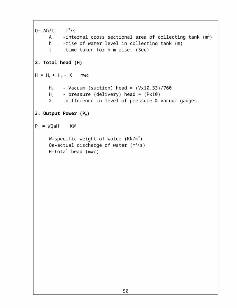
Q= Ah/t m3/sA -internal cross sectional area of collecting tank (m2)h -rise of water level in collecting tank (m)t -time taken for h-m rise. (Sec)
2. Total head (H)
H = Hs + Hd + X mwc
Hs - Vacuum (suction) head = (Vx10.33)/760Hd - pressure (delivery) head = (Px10)X -difference in level of pressure & vacuum gauges.
3. Output Power (Po)
Po = WQaH KW
W-specific weight of water (KN/m2) Qa-actual discharge of water (m3/s)H-total head (mwc)
33
NAME PLATE DETAILS: OBSERVATIONS
Pump: Area of the collecting tank (A) =Energy meter constant (Ne) =
No.of revolutions of energy meter (Nr) =Motor: Rise of water level in collecting tank (h) =
Speed of Crank Wheel (N) =Difference in level of pressure & vaccum gauge (X) =Diameter of piston (d) =Length of stroke (L) =
TABULATION FOR DOUBLE ACTING RECIPROCATING PUMP:
S.no
Pressure gauge
readingP
kg/cm2
Pressure head
Hd
(mwc)
Vacuum gauge
readingV
mm of Hg
Vacuum head
Hs
(mwc)
TotalHead
H(mwc
Time(t) for h cmrise of water sec
ActualDischarge
Qa
m3/s
Time forNr rev. of
energy meterdisc
T sec
Theoretical discharge
Qt
m3/s
% of
slip
Output power
Po
(Kw)
InputPower
Pi
(Kw)
Efficiency
η = Po/Pi
x100
1
2
3
4
5
6
34

35

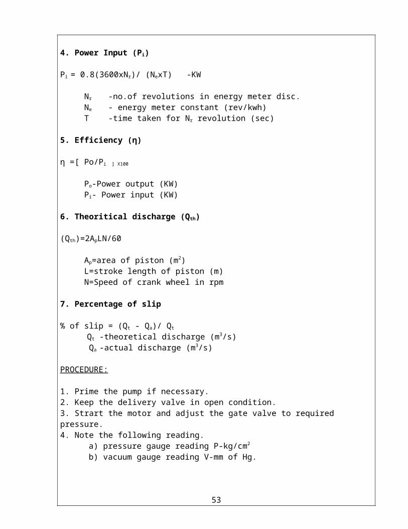
4. Power Input (Pi)
Pi = 0.8(3600xNr)/ (NexT) -KW
Nr -no.of revolutions in energy meter disc.Ne - energy meter constant (rev/kwh)T -time taken for Nr revolution (sec)
5. Efficiency (η)
η =[ Po/Pi ] X100
Po-Power output (KW)Pi- Power input (KW)
6. Theoritical discharge (Qth)
(Qth)=2ApLN/60
Ap=area of piston (m2)L=stroke length of piston (m)N=Speed of crank wheel in rpm
7. Percentage of slip
% of slip = (Qt - Qa)/ Qt
Qt -theoretical discharge (m3/s) Qa -actual discharge (m3/s)
PROCEDURE:
1. Prime the pump if necessary.2. Keep the delivery valve in open condition.3. Strart the motor and adjust the gate valve to required pressure.4. Note the following reading.
a) pressure gauge reading P-kg/cm2
b) vacuum gauge reading V-mm of Hg.c) time for h-m rise of water level in collecting tank-t sec.d) time of Nr revolution in energy meter T-sec.e) Difference in level between pressure & vacuum gauges.
Take minimum 6 set of readings by varying the head from 0 to 3 kg/cm2
The above procedure is repeated for different delivery valve openings and tabulated the readings.
36
GRAPH:
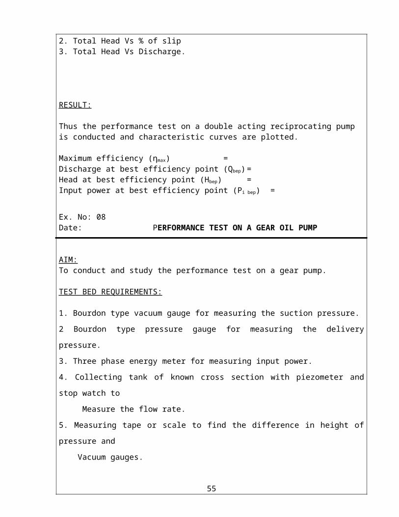
1. Total Head Vs Efficiency (η)2. Total Head Vs % of slip3. Total Head Vs Discharge.
RESULT:
Thus the performance test on a double acting reciprocating pump is conducted and characteristic curves are plotted.
Maximum efficiency (ηmax) =Discharge at best efficiency point (Qbep) =Head at best efficiency point (Hbep) =Input power at best efficiency point (Pi bep) =
37

Ex. No: 08Date: PERFORMANCE TEST ON A GEAR OIL PUMP
AIM:To conduct and study the performance test on a gear pump.
TEST BED REQUIREMENTS:
1. Bourdon type vacuum gauge for measuring the suction pressure.
2 Bourdon type pressure gauge for measuring the delivery pressure.
3. Three phase energy meter for measuring input power.
4. Collecting tank of known cross section with piezometer and stop watch to
Measure the flow rate.
5. Measuring tape or scale to find the difference in height of pressure and
Vacuum gauges.
DESCRIPTION:It is external gear pump and it comes under the positive displacement category. This consists of two spur gears, which are meshed externally with each other. They run in close contact within the casing and the fluid is trapped between the gears&casing and discharge in to the delivery pipe.Advantage.1. it handles viscous or heavy fluids2. Develops high pressure.3. Discharge at uniform rate (without fluctuations)
Limitation.Gear pumps cannot be used with outlet valve in fully closed condition. In such condition the pressure developed will either stop the pump or cause breakage.
FORMULAE USED :
1. Discharge (Q)
Q= Ah/t m3/sA -internal cross sectional area of collecting tank (m2)h -rise of oil level in collecting tank (m)t -time taken for h-m rise. (Sec)
2. Total head (H)
H = Hs +Hd +X mocHs -vacuum (suction) head= (vx10.33)/ (760xSp.gr of oil)Hd -Pressure (delivery) head= (px10)/Sp.gr of oilX - Deference in level of pressure & vacuum gauges.
38

NAME PLATE DETAILS: OBSERVATIONS:
Pump: Area of the collecting tank (A) =Energy meter constant (Ne) =
specific gravity of oil (s) =No.of revolutions of energy meter (Nr) =
Motor: Rise of oil level in collecting tank (h) =Difference in level between suctionand pressure gauges. (X) =
TABULATION FOR GEAR OIL PUMP:
S.no
Pressure gauge
readingP
(kg/cm2)
Delivery head
Hd
(moc)
Vacuumgauge
readingv
(mm of Hg)
VacuumheadHs
(moc)
Total head
H(moc)
Time(t) for ‘h’
cm rise of oil sec
Discharge
Qm3/s
Time for Nr
rev. of energy meter
discT sec
Output power
Po
(Kw)
InputPower
Pi
(Kw)
Efficiency
η = Po/Pi
x1001
2
3
4
5
6
39

3. Output Power (Po)Po = WQH
W -Specific weight of Oil (KN/m3)Q -Discharge of oil (m3/s)H -Total head (moc)
4. Power Input (Pi)Pi = 0.8(3600xNr)/ (NexT) KW
Nr -no. of revolutions in energy meter disc.Ne - energy meter constant (rev/kwh)T -time taken for Nr revolution (sec)
5. Efficiency (η)η= (po /pi )x` 100
po -Power output (KW)Pi -Power input (KW)
PROCEDURE:1. Prime the pump if necessary.
2. Keep the delivery valve in full open condition.
3. Start the motor and adjust the gate valve to required opening.
4. Note the following reading.
a) pressure gauge reading P-kg/cm2
b) Vacuum gauge reading. V-mm of Hg.
c) Time for h-m rise of oil level in collecting tank-t sec.
d) Time of Nr revolution in energy meter T-sec.
e) Difference in level between pressure& vacuum gauges. X-m
Take minimum 8 set of readings by varying the head from 0 to 4 kg/cm2
The above procedure is repeated for different delivery valve openings and tabulated the
readings.
GRAPH:1. Total Head Vs Efficiency (η)2. Total Head Vs power input (pi)3. Total Head Vs Discharge (Q)
RESULT:Thus the performance test on gear pump is conducted and characteristic curves are plotted.Maximum efficiency (ηmax) =Discharge at best efficiency point (Qbep) =Head at best efficiency point (Hbep) =Input power at best efficiency point (Pi bep) =
40
Ex. No: 09Date: PERFORMANCE TEST ON PELTON WHEEL TURBINE
AIM:
To study the characteristics of Pelton wheel turbine.
TEST BED REQUIREMENTS:
1 Pelton wheel turbine coupled with mechanical break drum.
2. Orificemeter fitted with pressure gauge in a pipeline for measuring flow rate.
3. Bourdon type pressure for measuring head over the turbine.
4. Spring balance and set of weight for loading the turbine.
5. Tachometer for measuring the speed of Francis turbine.
6. Measuring tape to measure the circumference of brake drum.
DESCRIPTION:
Pelton wheel turbine is a impulse type turbine, used to utilize the high heads for
generating power. All the available pressure energy is converted in to kinetic energy by means of
nozzle and spear arrangement. The water leaves the nozzle in the form of jet, this jet of water
strikes the buckets of the pelton wheel runner these buckets are in shape of double hemispherical
cup or bowl jointed at the middle portion by a wall known as splitter. The jet of water deflected
through more than 160-170 degree causing the change in momentum of jet and hence an
impulsive force is supplied to the cups, due to which the runner rotates. The specific speed of the
pelton wheel varies from 10-100.
41

FORMULAE USED:
1) Discharge.(Q)
Q = [a1a2 Ö(2gh) / Ö a12- a2
2 ] xCd m3/s
a1-area of the pipe (m2) a1 =( d12/4)
a2- area of throat (m2) a2 =( d22/4)
g-acceleration due to gravity (m/s2)
h-pressure difference in (m)
2) Total head (H)
H =( Px10)-[(V x 10.33) /760) mwcP-pressure gauge reading (kg/cm2)V-Vacuum gauge reading (mm of Hg)
3) Pressure difference (h)
h = X[(Sm/ Sw)-1] m
X—difference in manometer reading (h1-h2)m
Sm—Specific gravity of mercury (13.6)
Sw—Specific gravity of water(1)
4) Torque (T)
(W1ہW2) xRxg Nm
5) Input Power (Pi)
Pi = ρ gQH (KW) 1000
ρ- density of waterQ- Discharge (m3/s)H- Total head (mwc)
4) Output power (Po)
Po = 2NT/ (1000x60) KWT –torque (Nm); N- Speed of turbine (rpm)
5) Efficiency (η)
η = (Po/Pi)x100
42
NAME PLATE DETAILS: OBSERVATIONS:
Pump: Nozzle opening position =Radius of Break drum (R) m =
Diameter of inlet pipe (d1) m =Diameter of throat pipe (d2) m =
Turbine:
TABULATION FOR PELTON WHEEL TURBINE :
S.no
Pressure gauge
readingP
kg/cm2
VacuumGauge reading
Vmm of
Hg
TotalHead
Hm of water
manometer readings (m)
h1 h2 h cm cm m
Flowrate
Qm3/s
Speed
Nrpm
weight
W1 W2(kg) (kg)
W=W1ہW2(kg)
Torque
T(Nm)
Output power
Po
(Kw)
InputPower
Pi
(Kw)
Efficiency
η = Po/Pi
x100
1
2
3
4
5
6
43
PROCEDURE:
1. Keep the nozzle opening at required opening
2. Prime the pump if necessary.
3. Close the sluice and start the pump.
4. The start button should be kept pressed for 5-10 seconds and then released.
5. Open the delivery valve for required pressure.
6. Load the turbine by adding the weight to the hanger.
7. Note the load on the hanger, spring balance load, orificemeter pressure gauge reading, speed
& inlet pressure gauge reading.
8. Repeat the experiment for various loads.
GRAPH:
1. Speed (N) Vs Efficiency (η)2. Speed (N) Vs Input power (Pi)3. Speed (N) Vs Discharge (Q)
RESULT:
Thus the performance test on a Kaplan turbine is conducted and characteristic curves are plotted.
Maximum efficiency (ηmax) =Discharge at best efficiency point (Qbep) =Head at best efficiency point (Hbep) =Input power at best efficiency point (Pi bep) =Output power at best efficiency point (Po bep) =
44
Ex. No: 10Date: PERFORMANCE TEST ON FRANCIS TURBINE
AIM:To study the characteristics of Francis turbine.
TEST BED REQUIREMENTS:
1 Francis turbine coupled with mechanical break drum.2. Orifice meter fitted with pressure gauge in a pipeline for measuring flow rate.3. Bourdon type pressure for measuring head over the turbine.4. Spring balance and set of weight for loading the turbine.5. Tachometer for measuring the speed of Francis turbine.6. Measuring tape to measure the circumference of brake drum.
DESCRIPTION:Francis turbine is an inward flow reaction turbine used in dams and reservoirs of low
height to convert hydraulic energy in to mechanical energy. They are best suited for low heads say 50 to 250 m.
Water under pressure from pump enters through the volute casing and the guide vanes in to the runner. While passing through the spiral casing and guide vanes, a portion of pressure energy (potential energy) is converted in to velocity energy (kinetic energy).Water thus enters the runner at a high velocity and as it passes through the runner vanes, the remaining potential energy is converted in to kinetic energy. Due to then curvature of the vanes, the kinetic energy is transformed in to mechanical energy i.e., the water head is converted in to mechanical energy and hence runner rotates. The water from the runner is discharged in to the tailrace, the discharge through runner can be regulated by the operating guide vanes also.
FORMULAE USED:
1) Discharge.(Q)
Q = [a1a2 Ö(2gh) / Ö a12- a2
2 ] xCd m3/s
a1-area of the pipe (m2) a1 =( d12/4)
a2- area of throat (m2) a2 =( d22/4)
g-acceleration due to gravity (m/s2)
h-pressure difference in (m)
2) Total head (H)
H =( Px10)-[(V x 10.33) /760) mwcP-pressure gauge reading (kg/cm2)V-Vacuum gauge reading (mm of Hg)
45

3) Pressure difference (h)
h = X[(Sm/ Sw)-1] m
X—difference in manometer reading (h1-h2)m
Sm—Specific gravity of mercury (13.6)
Sw—Specific gravity of water(1)
4) Torque (T)
(W1ہW2) xRxg Nm
5) Input Power (Pi)
Pi = ρ gQH (KW) 1000
ρ- density of waterQ- Discharge (m3/s)H- Total head (mwc)
4) Output power (Po)
Po = 2NT/ (1000x60) KW
T –torque (Nm)N- Speed of turbine (rpm)
5) Efficiency (η)
η = (Po/Pi)x100
46

NAME PLATE DETAILS: OBSERVATIONS:
Pump: Radius of Break drum (R) m = Diameter of inlet pipe (d1) m =
Diameter of throat pipe (d2) m =Turbine:
TABULATION FOR FRANCIS TURBINE:
S.no
Pressure gauge
readingP
kg/cm2
VacuumGauge reading
Vmm of
Hg
TotalHead
Hm of water
manometerpressure gauge readings (m)
h1 h2 h cm cm m
Flowrate
Qm3/s
Speed
Nrpm
weight
W1 W2(kg) (kg)
W=W1ہW2(kg)
Torque
T(Nm)
Output power
Po
(Kw)
InputPower
Pi
(Kw)
Efficiency
η = Po/Pi
x100
1
2
3
4
5
6
47

PROCEDURE:1) Keep the guide vane opening at required opening2) Prime the pump if necessary.3) Close the gate valve and start the pump.4) The start button should be kept pressed for 5-10 seconds and then released.5) Open the delivery valve for required pressure.6) Load the turbine by adding the weight to the hanger.7) Note the load on the hanger, spring balance load, orifice meter pressure gauge reading,
speed & inlet pressure gauge reading.8) Repeat the experiment for various loads.
GRAPH:1. Discharge (Q) Vs Efficiency (η)2. Discharge (Q) Vs Input power (Pi)3. Discharge (Q) Vs Speed (N)
RESULT:
Thus the performance test on a Francis turbine is conducted and characteristic curves are plotted.
Maximum efficiency (ηmax) =Discharge at best efficiency point (Qbep) =Head at best efficiency point (Hbep) =Input power at best efficiency point (Pi bep) =Output power at best efficiency point (Po bep) =
48

Ex. No: 11Date: PERFORMANCE TEST ON KAPLAN TURBINE
AIM:To study the characteristics of Kaplan turbine.
TEST BED REQUIREMENTS:
1 Kaplan turbine coupled with mechanical break drum.2. Orificemeter fitted with manometer in a pipe line for measuring flow rate.3. Bourdon type pressure for measuring head over the turbine.4. Spring balance and set of weight for loading the turbine.5. Tachometer for measuring the speed of Kaplan turbine.6. Measuring tape to measure the circumference of brake drum.
DESCRIPTION:
Kaplan turbine is an axial flow reaction turbine used in dams and reservoirs of low height to convert hydraulic energy in to mechanical energy. They are best suited for low heads say 10 to 50 m. The specific speed ranges 200 to 1000.
Water under pressure from pump enters through the volute casing and the guide vanes in to the runner. While passing through the spiral casing and guide vanes, a portion of pressure energy(potential energy) is converted in to velocity energy (kinetic energy).Water thus enters the runner at a high velocity and as it passes through the runner vanes, the remaining potential energy is converted in to kinetic energy. Due to then curvature of the vanes, the kinetic energy is transformed in to mechanical energy i.e., the water head is converted in to mechanical energy and hence runner rotates. The water from the runner is discharged in to the tail race, the discharge through runner can be regulated by the operating guide vanes also.
FORMULA USED:
1) Discharge.(Q)
Q = [a1a2 Ö(2gh) / Ö a12- a2
2 ] xCd m3/s
a1-area of the inlet pipe (m2) a1 =( d12/4)
a2- area of throat (m2) a2 =( d22/4)
g-acceleration due to gravity (m/s2)
h-pressure difference (m)
2) Total head (H)
H = (Px10)-[(V x 10.33) /760)] mwcP-pressure gauge reading (kg/cm2)V-Vacuum gauge reading (mm of Hg)
49
3) Pressure difference (h)
h = X[(Sm/ Sw)-1] m
X—difference in manometer reading (h1-h2) m
Sm—Specific gravity of mercury (13.6)
Sw—Specific gravity of water (1)
4) Torque (T)
(W1ہW2) xRxg NmR- radius of brake drum
5) Input Power (Pi)
Pi = ρ gQH (KW) 1000
ρ- density of waterQ- Discharge (m3/s)H- Total head (mwc)
4) Output power (Po)
Po = 2NT/ (1000x60) KW
T –torque (Nm)N- Speed of turbine (rpm)
5) Efficiency (η)
η = (Po/Pi)x100
50

NAME PLATE DETAILS: OBSERVATIONS:
Pump: Radius of Break drum (R) m = Diameter of inlet pipe (d1) m =
Turbine: Diameter of throat pipe (d2) m =
TABULATION FOR KAPLAN TURBINE:
S.no
Pressure gauge
readingP
kg/cm2
VacuumGauge reading
Vmm of
Hg
TotalHead
Hm of water
manometerreadings (m)
h1 h2 h cm cm m
Flowrate
Qm3/s
Speed
Nrpm
weight
W1 W2(kg) (kg)
W=W1ہW2(kg)
Torque
T(Nm)
Output power
Po
(Kw)
InputPower
Pi
(Kw)
Efficiency
η = Po/Pi
x100
1
2
3
4
5
6
51
PROCEDURE:
1) Keep the guide vanes opening at required opening.2) Prime the pump if necessary.3) Close the gate valve and start the pump.4) The start button should be kept pressed for 5-10 seconds and then released.5) Open the delivery valve for required pressure.6) Load the turbine by adding the weight to the hanger.7) Note the load on the hanger, spring balance load, manometer reading, speed,
pressure & vacuum gauge reading.8) Repeat the experiment for various loads.
GRAPH:
1. Discharge (Q) Vs Efficiency (η)2. Discharge (Q) Vs Input power (Pi)3. Discharge (Q) Vs Speed (N)
RESULT:
Thus the performance test on a Kaplan turbine is conducted and characteristic curves are plotted.
Maximum efficiency (ηmax) =Discharge at best efficiency point (Qbep) =Head at best efficiency point (Hbep) =Input power at best efficiency point (Pi bep) =Output power at best efficiency point (Po bep) =
52
VIVA (SAMPLE QUESTIONS)
1) Define flow meters.
2) What are the types of flow meters?
3) What is the principle of orifice meter?
4) What are the advantages of orifice meter over than flow meters?
5) What is vena-contraction?
6) What is the use of rotameter?
7) Write the Bernoulli’s equation between inlet and orifice plate?
8) What is the use of venturimeter?
9) What are the important components of venturimeter?
10) Why is the length of diverging zone greater than that of converging zone in case of
venturimeter?
11) Compare the Cd of venturimeter with other flow meters.
12) What is meant by diameter ratio in venturimeter and orifice meter?
13) Determination of pipe Friction Factor
14) Losses in pipe flow due to change of section and change of direction.
15) Why does pressure along a horizontal pipe go on decreasing?
16) On what factors Darcy’s friction factor depending?
17) What are HGL and TEL?
18) Difference major and minor losses?
19) Define Pump.
20) What is jet pump?
21) What is the specific use of jet pump?
22) Under what circumstances it is very useful?
23) What is the energy conservation that takes place in the case of a pump?
24) What is the working principle of centrifugal pump?
25) Define specific speed of a pump?
26) What is NPSH of a pump?
27) What is the purpose of foot valve?
28) What is meant by priming?
53

29) Give the working principle of reciprocating pump?
30) What is the difference between SARP and DARP?
31) What is the use of air vessel?
32) What is indicator diagram?
33) Which type of pump is used for general day to day purpose?
34) What is multi-stage pump?
35) How many impellers are there in the submersible pump?
36) What is the signifance of specific speed?
37) Mention the importance characteristics of submersible pump?
38) Define turbine.
39) What is an impulse turbine?
40) In what way is it different from reaction turbine?
41) What is the need for casing in pelton wheel?
42) Define specific speed?
43) Differentiate between impulse and reaction turbine.
44) When the load on shaft changes, why does discharge entering the turbine change
and how?
45) What is the purpose of a draft tube?
46) Define specific speed of a turbine?
47) State the function of spiral casing.
48) Give the working principle of gear pump & Give its uses.
49) What are the other rotary pumps?
50) What is the maximum Pressure that can be developed by the gear pump?
54
REFERENCES:
1. Fluid mechanics and Machinery - R.K.Bansal.
2. Engineering Fluid mechanics - K.L.Kumar.
3 Fluid mechanics and Machinery - D.S.Kumar.
4. Fluid Mechanics, Hydraulics and Fluid Machines - S.Ramamirtham
5. Fluid mechanics - Streeter and Wylie.
6. Fluid mechanics and Machinery - R.K.Rajput.
7. Introduction to Fluid mechanics - Fox McDonald.
8. Fluid mechanics - Modi and Sethi.
9. Hydraulic Machines – Jagdish Lal.
10. Fundamentals of Compressible Flow - S.M.Yahya.
55


