Fluid Machines - Edutalks.orgClassification of pumps In positive displacement pumps, fluid is drawn...
31
Fluid Machines Prepared by: AREEF A AP/ ME AL AMEEN ENGINEERING COLLEGE Shoranur Areef A Al- Ameen Engg. College www.edutalks.org
Transcript of Fluid Machines - Edutalks.orgClassification of pumps In positive displacement pumps, fluid is drawn...
Fluid Machines
Prepared by: AREEF A
AP/ ME
AL AMEEN ENGINEERING COLLEGE
Shoranur
Areef A Al- Ameen Engg. College
www.edutalks.org
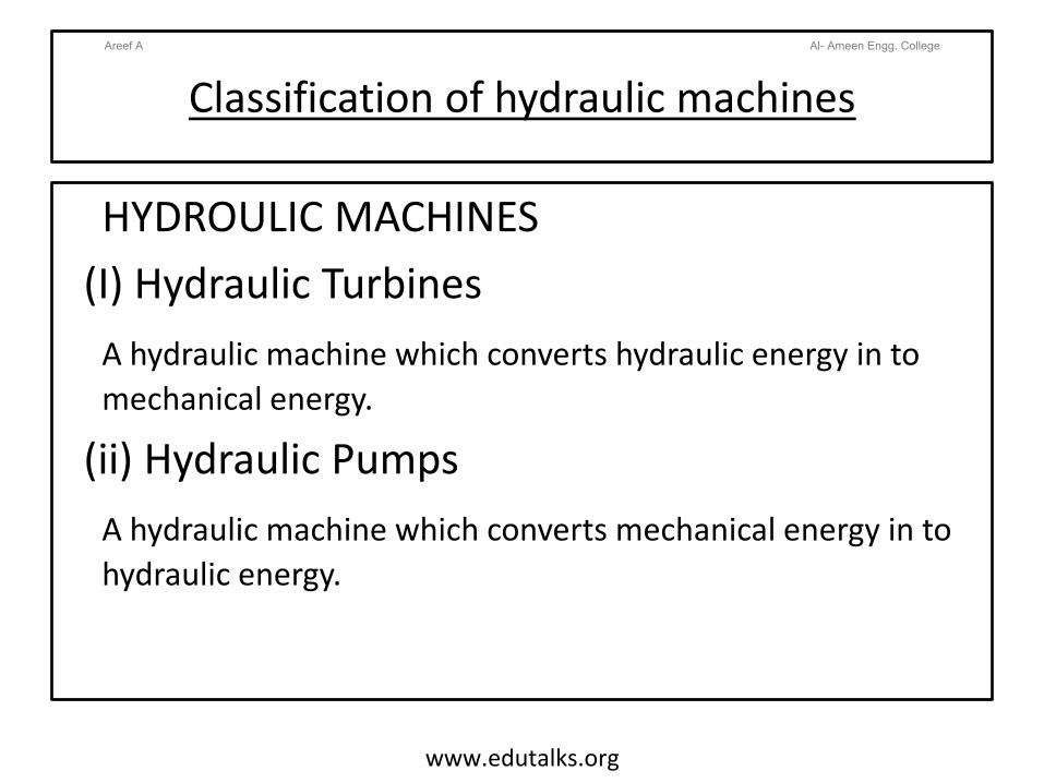
Classification of hydraulic machines
HYDROULIC MACHINES(I) Hydraulic Turbines
A hydraulic machine which converts hydraulic energy in to mechanical energy.
(ii) Hydraulic PumpsA hydraulic machine which converts mechanical energy in to hydraulic energy.
Areef A Al- Ameen Engg. College
www.edutalks.org
Pumps
• A pump is a machine which is used to raise or
transfer the fluids.
•It is also used to maintain the constant flow rate
or constant pressure.
•It is normally driven by a engine or a motor.
• Pumps are rated by the horse power (hp).
Areef A Al- Ameen Engg. College
www.edutalks.org
CLASSIFICATION OF PUMPSAreef A Al- Ameen Engg. College
www.edutalks.org
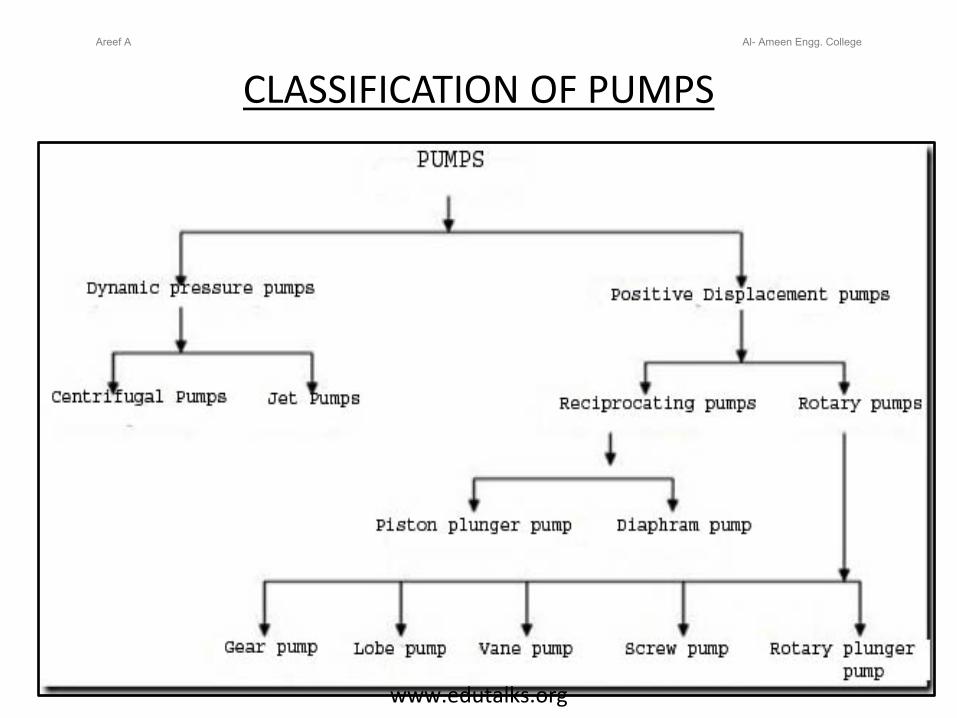
Classification of pumps
In positive displacement pumps, fluid is drawn or forced into a finite space and it is sealed.It is then forced out and the cycle is repeated.
In dynamic pressure pumps, centrifugal force is used to move the fluid into a pipe.
Areef A Al- Ameen Engg. College
www.edutalks.org
Reciprocating Pumps
It is a positive displacement pump
It uses a piston and cylinder
arrangement with suction and delivery
valves integrated with the pump.
Areef A Al- Ameen Engg. College
www.edutalks.org

Reciprocating Pumps
It is a positive displacement pump
It sucks and raises the liquid by actually
displacing it with a piston/plunger that
executes a reciprocating motion in a
closely fitting cylinder.
Areef A Al- Ameen Engg. College
www.edutalks.org

Working of single acting Reciprocating Pump
Single Acting Reciprocating Pump
Areef A Al- Ameen Engg. College
www.edutalks.org

Working of single acting Reciprocating Pump
During suction stroke the piston moves to the left, causing the inlet valve to open.Water is admitted into the cylinder through the inlet valve. During the discharge stroke the piston moves to the right closes the suction valve and opens the out let valve. Through the outlet valve the volume of liquid moved out of the cylinder.
Areef A Al- Ameen Engg. College
www.edutalks.org
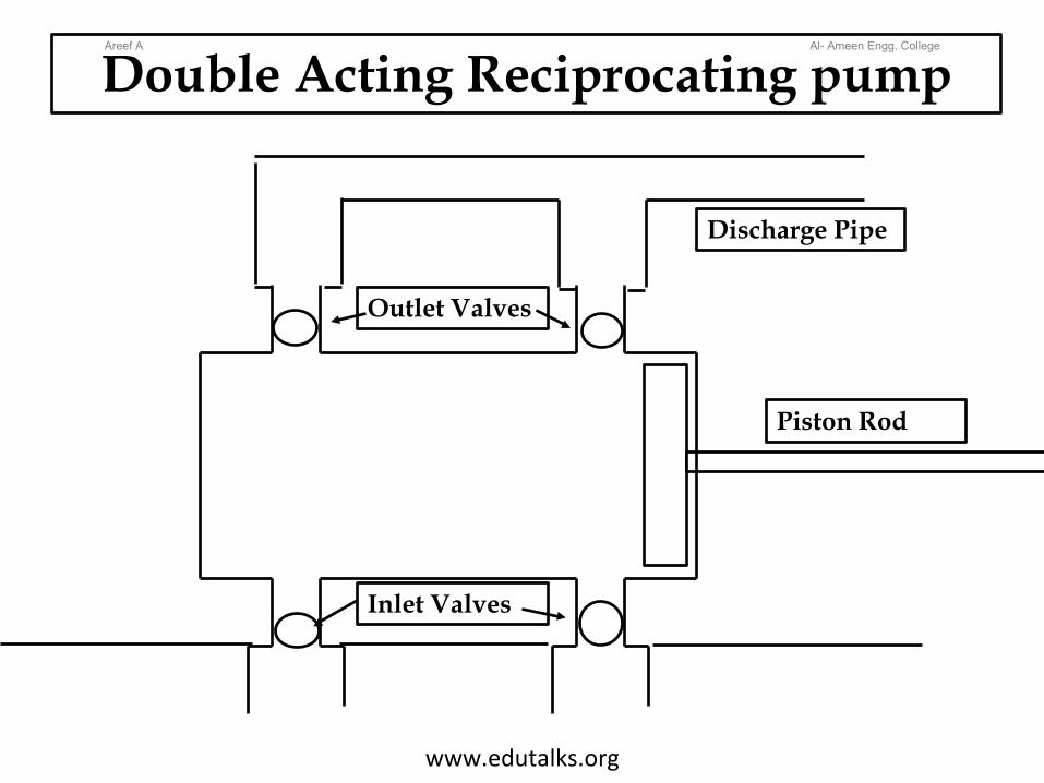
Double Acting Reciprocating pump
Discharge Pipe
Piston Rod
Inlet Valves
Outlet Valves
Areef A Al- Ameen Engg. College
www.edutalks.org
Double Acting Reciprocating Pump -Working
• Each cycle consists of two strokes.• Both the strokes are effective, hence it is known as double acting pump• Liquid is filled at one end and discharged at other end during forward stroke.• During the return stroke, end of cylinder just emptied is filled and the end just filled is emptied.
Areef A Al- Ameen Engg. College
www.edutalks.org
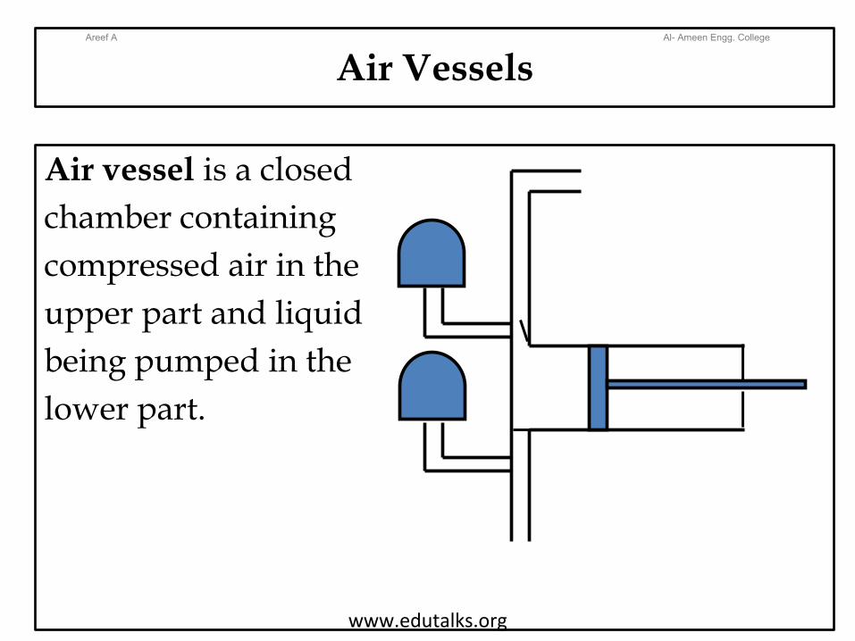
Air Vessels
Air vessel is a closed chamber containing compressed air in the upper part and liquid being pumped in the lower part.
Areef A Al- Ameen Engg. College
www.edutalks.org
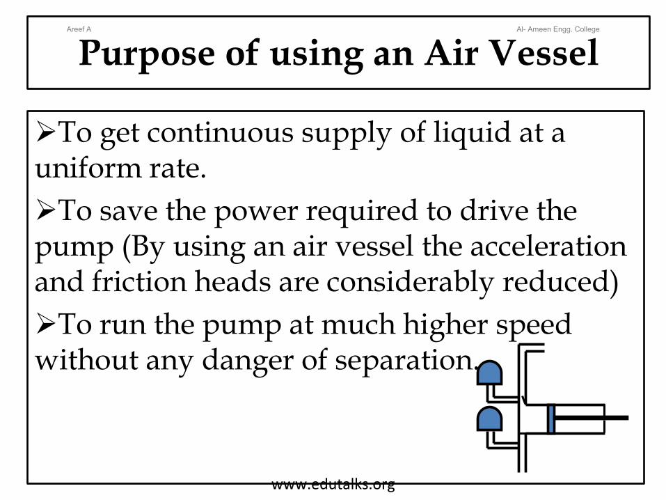
Purpose of using an Air Vessel
To get continuous supply of liquid at a uniform rate.To save the power required to drive the pump (By using an air vessel the acceleration and friction heads are considerably reduced)To run the pump at much higher speed without any danger of separation.
Areef A Al- Ameen Engg. College
www.edutalks.org
Advantages of reciprocating pump
• Relatively compact design
• High viscosity performance
• Ability to handle high differential
pressure.
Areef A Al- Ameen Engg. College
www.edutalks.org
Centrifugal PumpsAreef A Al- Ameen Engg. College
www.edutalks.org
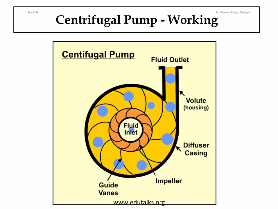
Centrifugal Pump - WorkingAreef A Al- Ameen Engg. College
www.edutalks.org

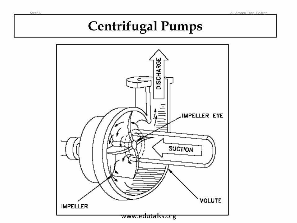
Components of Centrifugal pump
A rotating component comprising of an impeller and a shaft.
A stationery component comprising a volute (casing).
Delivery pipe
Suction pipe
Areef A Al- Ameen Engg. College
www.edutalks.org
Working Principle of Centrifugal pump
The delivery valve is closed and the pump is primed, so that no air pocket is left.
Keeping the delivery valve still closed the electric motor is started to rotate the impeller.
The rotation of the impeller is gradually increased till the impeller rotates at its normal speed.
After the impeller attains the normal speed the delivery valve is opened when the liquid is sucked continuously up to the suction pipe.
Areef A Al- Ameen Engg. College
www.edutalks.org

Working Principle of Centrifugal pumpIt passes through the eye of the casing and enters the impeller at its centre.
The liquid is impelled out by the rotating vanes and it comes out at the outlet tips of the vanes into the casing.
Due to the impeller action the pressure head as well as the velocity heads are increased.
From the casing the liquid passes into the pipe and lifted to the required height.When pump is to be stopped the delivery valve is to be first closed, other wise there may be some backflow of water into the reservoir.
Areef A Al- Ameen Engg. College
www.edutalks.org
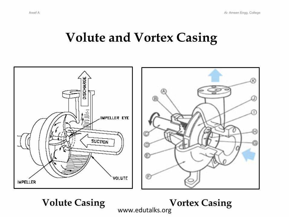
Volute and Vortex Casing
Volute Casing Vortex Casing
Areef A Al- Ameen Engg. College
www.edutalks.org
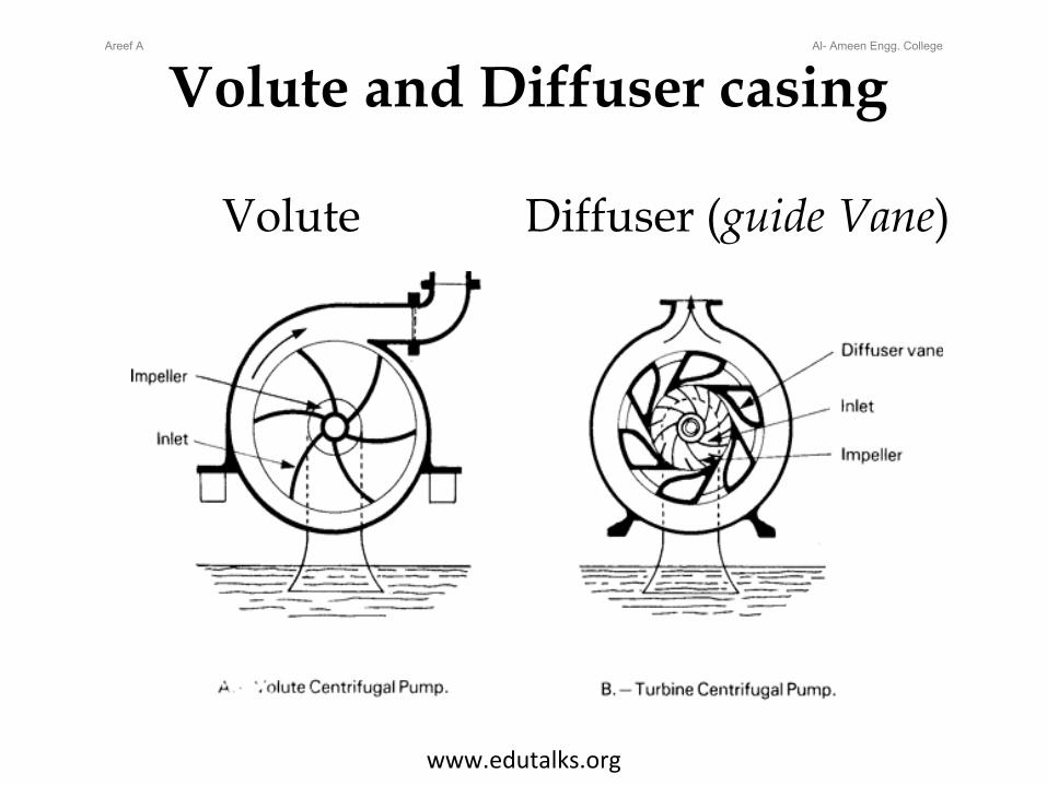
Volute and Diffuser casing
Volute Diffuser (guide Vane)
Areef A Al- Ameen Engg. College
www.edutalks.org

Volute and Diffuser casing
Volute Casing: In this type of casing the area of flow gradually increases from the impeller outlet to the delivery pipe.Vortex Casing: If a circular chamber is provided between the impeller and volute chamber the casing is known as Vortex Chamber.Diffuser C : The impeller is surrounded by a diffuser.The guide vanes are designed in such a way that the water from the impeller enters the guide vanes without shock. It reduces the vibration of the pump. Diffuser casing, the diffuser and the outer casing are stationery parts.
Areef A Al- Ameen Engg. College
www.edutalks.org
Priming of a centrifugal Pump
The operation of filling the suction pipe, casing and a portion of delivery pipe with the liquid to be raised, before starting the pump is known as PrimingIt is done to remove any air, gas or vapour from these parts of pump.If a Centrifugal pump is not primed before starting air pockets inside impeller may give rise to vortices and causes discontinuity of flow
Areef A Al- Ameen Engg. College
www.edutalks.org

TURBINES
Turbines are defined as the hydraulicmachines which convert Hydraulic energy in toMechanical energy.
Areef A Al- Ameen Engg. College
www.edutalks.org
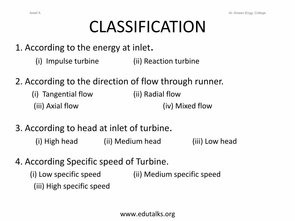
CLASSIFICATION1. According to the energy at inlet.
(i) Impulse turbine (ii) Reaction turbine
2. According to the direction of flow through runner.(i) Tangential flow (ii) Radial flow (iii) Axial flow (iv) Mixed flow
3. According to head at inlet of turbine.(i) High head (ii) Medium head (iii) Low head
4. According Specific speed of Turbine.(i) Low specific speed (ii) Medium specific speed
(iii) High specific speed
Areef A Al- Ameen Engg. College
www.edutalks.org
IMPULSE TURBINEAreef A Al- Ameen Engg. College
www.edutalks.org
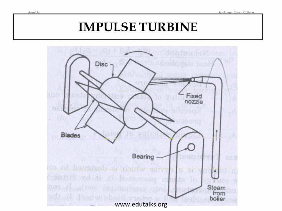
IMPULSE TURBINE
• The steam coming out at a very high velocity through the nozzle impinges on the blades fixed on the periphery of rotor.• The blades change the direction of steam flow without change in pressure.• The resulting force causes the rotation of the turbine.E.g Pelton wheel.
Areef A Al- Ameen Engg. College
www.edutalks.org
REACTION TURBINE
Areef A Al- Ameen Engg. College
www.edutalks.org
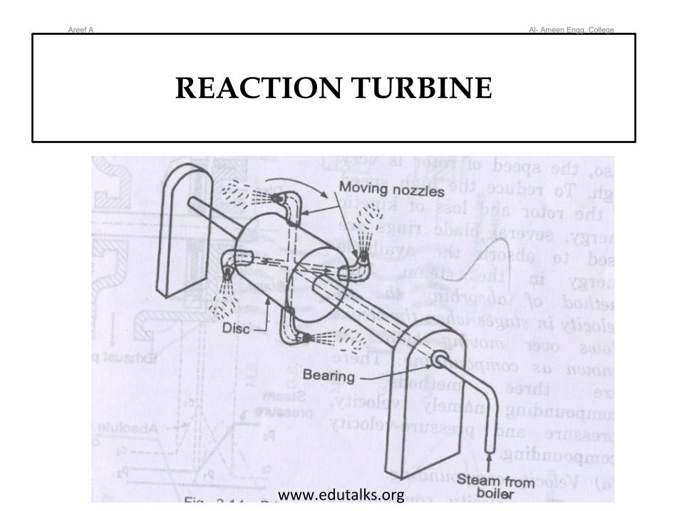
REACTION TURBINE
• The high pressure steam from the boiler is passed through the nozzles.• When the steam comes out through these nozzles, the velocity of steam increases relative to the rotating disc.• The resulting force of steam on nozzle gives the rotating motion to the disc and the shaft.• The shaft rotates in opposite direction of the steam.E.g Francis Turbine, Kaplan Turbine.
Areef A Al- Ameen Engg. College
www.edutalks.org
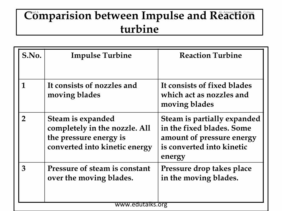
Comparision between Impulse and Reaction turbine
S.No. Impulse Turbine Reaction Turbine
1 It consists of nozzles and moving blades
It consists of fixed blades which act as nozzles and moving blades
2 Steam is expanded completely in the nozzle. All the pressure energy is converted into kinetic energy
Steam is partially expanded in the fixed blades. Some amount of pressure energy is converted into kinetic energy
3 Pressure of steam is constant over the moving blades.
Pressure drop takes place in the moving blades.
Areef A Al- Ameen Engg. College
www.edutalks.org
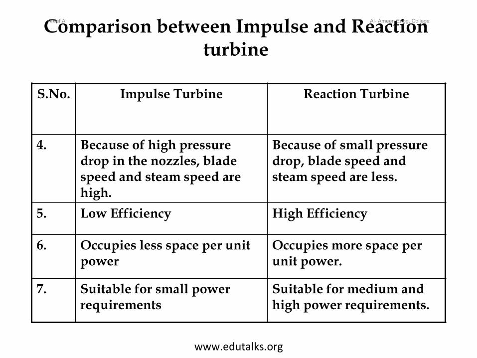
Comparison between Impulse and Reaction turbine
S.No. Impulse Turbine Reaction Turbine
4. Because of high pressure drop in the nozzles, blade speed and steam speed are high.
Because of small pressure drop, blade speed and steam speed are less.
5. Low Efficiency High Efficiency
6. Occupies less space per unit power
Occupies more space per unit power.
7. Suitable for small power requirements
Suitable for medium and high power requirements.
Areef A Al- Ameen Engg. College
www.edutalks.org