FLUID COUPLINGS KR, KS…, EK...FLUID COUPLINGS INSTALLATION AND MAINTENANCE 4 FIG. 7 57 150 GB -...
16
INSTALLATION AND MAINTENANCE BEFORE ASSEMBLING AND OPERATING THE FLUID COUPLING, CAREFULLY READ ALL THE SAFETY AND OPERATING INSTRUCTIONS REPORTED IN THIS MANUAL. ALWAYS FOLLOW ALL THE INSTRUCTIONS AND ASSURE THAT ALL THE OPERATORS STANDING BY THE MACHINERY ARE WEARING ALL THE PROTECTIVE EQUIPMENT NECESSARY FOR THE JOB TYPE AND APPLICATION BEING PERFORMED. DO NOT USE THE MACHINERY IF YOU DO NOT UNDERSTAND THESE INSTRUCTIONS, AND IMMEDIATELY REFER TO THE MANUFACTURER OR THE CUSTOMER SERVICE DESK FOR ASSISTANCE. THE COUPLING MUST BE PROTECTED BY A CONVENIENT COVER GUARD TO AVOID PERSONAL INJURY TO PEOPLE. AXIAL AND RADIAL VENTILATION OPENINGS SHOULD BE INCORPORATED IN THE GUARD FOR HEAT EXCHANGE. IF THE COUPLING IS FITTED WITH FUSIBLE PLUGS, THE SAID OPENINGS SHOULD NOT BE DIRECTED TOWARDS OPERATORS OR ANY HOT OR ELECTRICAL INSTALLATION. FLUID COUPLINGS ...KR..., ...KS…, EK
Transcript of FLUID COUPLINGS KR, KS…, EK...FLUID COUPLINGS INSTALLATION AND MAINTENANCE 4 FIG. 7 57 150 GB -...

INSTALLATION AND MAINTENANCE
BEFORE ASSEMBLING AND OPERATING THE FLUID COUPLING,CAREFULLY READ ALL THE SAFETY AND OPERATINGINSTRUCTIONS REPORTED IN THIS MANUAL.
ALWAYS FOLLOW ALL THE INSTRUCTIONS AND ASSURE THAT ALLTHE OPERATORS STANDING BY THE MACHINERY ARE WEARINGALL THE PROTECTIVE EQUIPMENT NECESSARY FOR THE JOBTYPE AND APPLICATION BEING PERFORMED.
DO NOT USE THE MACHINERY IF YOU DO NOT UNDERSTANDTHESE INSTRUCTIONS, AND IMMEDIATELY REFER TO THEMANUFACTURER OR THE CUSTOMER SERVICE DESK FORASSISTANCE.
THE COUPLING MUST BE PROTECTED BY A CONVENIENT COVERGUARD TO AVOID PERSONAL INJURY TO PEOPLE.AXIAL AND RADIAL VENTILATION OPENINGS SHOULD BEINCORPORATED IN THE GUARD FOR HEAT EXCHANGE.
IF THE COUPLING IS FITTED WITH FUSIBLE PLUGS, THE SAIDOPENINGS SHOULD NOT BE DIRECTED TOWARDS OPERATORSOR ANY HOT OR ELECTRICAL INSTALLATION.
FLUID COUPLINGS...KR..., ...KS…, EK
copertina 150 GB 17-11-2010 11:22 Pagina 2
1
FLUID COUPLINGS
INSTALLATION AND MAINTENANCE
150 GB - 1010
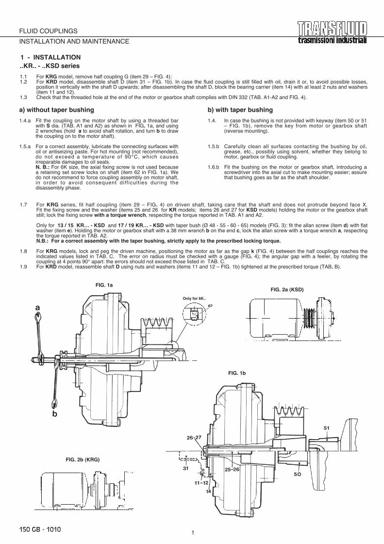
1 - INSTALLATION
a) without taper bushing
1.4.a Fit the coupling on the motor shaft by using a threaded barwith S dia. (TAB. A1 and A2) as shown in FIG. 1a, and using2 wrenches (hold a to avoid shaft rotation, and turn b to drawthe coupling on to the motor shaft).
1.5.a For a correct assembly, lubricate the connecting surfaces withoil or antiseizing paste. For hot mounting (not recommended),do not exceed a temperature of 90°C, which causesirreparable damages to oil seals.N. B.: For 6K size, the axial fixing screw is not used becausea retaining set screw locks on shaft (item 62 in FIG. 1a). Wedo not recommend to force coupling assembly on motor shaft,in order to avoid consequent diff icult ies during thedisassembly phase.
b) with taper bushing
1.4. In case the bushing is not provided with keyway (item 50 or 51– FIG. 1b), remove the key from motor or gearbox shaft(reverse mounting).
1.5.b Carefully clean all surfaces contacting the bushing by oil,grease, etc., possibly using solvent, whether they belong tomotor, gearbox or fluid coupling.
1.6.b Fit the bushing on the motor or gearbox shaft, introducing ascrewdriver into the axial cut to make mounting easier; assurethat bushing goes as far as the shaft shoulder.
..KR.. - ..KSD series
1.1 For KRG model, remove half coupling G (item 29 – FIG. 4); 1.2 For KRD model, disassemble shaft D (item 31 – FIG. 1b). In case the fluid coupling is still filled with oil, drain it or, to avoid possible losses,
position it vertically with the shaft D upwards; after disassembling the shaft D, block the bearing carrier (item 14) with at least 2 nuts and washers(item 11 and 12).
1.3 Check that the threaded hole at the end of the motor or gearbox shaft complies with DIN 332 (TAB. A1-A2 and FIG. 4).
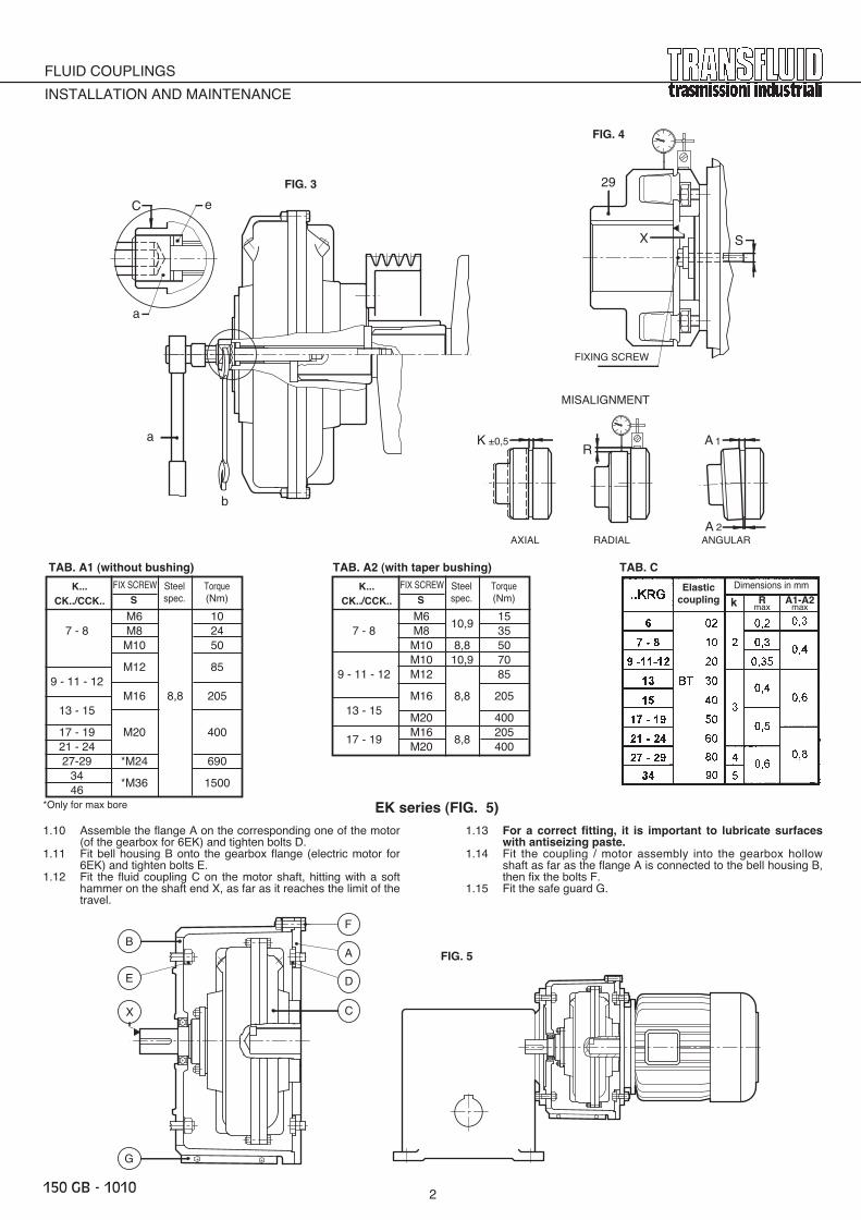
1.7 For KRG series, fit half coupling (item 29 – FIG. 4) on driven shaft, taking care that the shaft end does not protrude beyond face X.Fit the fixing screw and the washer (items 25 and 26 for KR models; items 26 and 27 for KSD models) holding the motor or the gearbox shaftstill; lock the fixing screw with a torque wrench, respecting the torque reported in TAB. A1 and A2.
Only for 13 / 15 KR… - KSD and 17 / 19 KR… - KSD with taper bush (Ø 48 - 55 - 60 - 65) models (FIG. 3): fit the allan screw (item d) with flatwasher (item e). Holding the motor or gearbox shaft with a 38 mm wrench b on the end c, lock the allan screw with a torque wrench a, respectingthe torque reported in TAB. A2.N.B.: For a correct assembly with the taper bushing, strictly apply to the prescribed locking torque.
1.8 For KRG models, lock and peg the driven machine, positioning the motor as far as the gap k (FIG. 4) between the half couplings reaches theindicated values listed in TAB. C. The error on radius must be checked with a gauge (FIG. 4); the angular gap with a feeler, by rotating thecoupling at 4 points 90° apart: the errors should not exceed those listed in TAB. C.
1.9 For KRD model, reassemble shaft D using nuts and washers (items 11 and 12 – FIG. 1b) tightened at the prescribed torque (TAB. B).
FIG. 1a
FIG. 1b
FIG. 2a (KSD)
FIG. 2b (KRG)
Only for 6K..
150 GB 1010 17-11-2010 9:19 Pagina 1
FLUID COUPLINGS
INSTALLATION AND MAINTENANCE
2150 GB - 1010
1.10 Assemble the flange A on the corresponding one of the motor(of the gearbox for 6EK) and tighten bolts D.
1.11 Fit bell housing B onto the gearbox flange (electric motor for6EK) and tighten bolts E.
1.12 Fit the fluid coupling C on the motor shaft, hitting with a softhammer on the shaft end X, as far as it reaches the limit of thetravel.
1.13 For a correct fitting, it is important to lubricate surfaceswith antiseizing paste.
1.14 Fit the coupling / motor assembly into the gearbox hollowshaft as far as the flange A is connected to the bell housing B,then fix the bolts F.
1.15 Fit the safe guard G.
TAB. A1 (without bushing) TAB. A2 (with taper bushing) TAB. C
EK series (FIG. 5)
kK...
CK../CCK..
FIX SCREW
SSteelspec.
Torque(Nm)
M610,9
157 - 8 M8 35
M10 8,8 50M10 10,9 70
9 - 11 - 12 M12 85
M16 8,8 20513 - 15
M20 400
17 - 19M16
8,8205
M20 400
K...CK../CCK..
FIX SCREW
SSteelspec.
Torque(Nm)
M6 107 - 8 M8 24
M10 50
9 - 11 - 12M12 85
M16 8,8 20513 - 15
17 - 19 M20 40021 - 2427-29 *M24 690
34*M36 1500
46
Rmax
A1-A2max
150 IT_02
ANGOLARERADIALEASSIALE
DISALLINEAMENTO
FIG. 4
TIRANTE
FIG. 3 29
X
1
2
RK
A
A±0,5
S
b
a
a
C e
150 IT_02
FIG. 5
X
G
E
B
F
A
D
C
FIG. 3
FIG. 4
FIG. 5
*Only for max bore
MISALIGNMENT
ANGULARRADIALAXIAL
Elasticcoupling
Dimensions in mm
FIXING SCREW
150 GB 1010 17-11-2010 9:19 Pagina 8

FLUID COUPLINGS
INSTALLATION AND MAINTENANCE
3150 GB - 1010
..KRM series (FIG. 4a)
1.16 Assemble fluid coupling as reported in par. 1.1 to 1.71.17 Fit the hub (item 29a) on the driven shaft, lock and peg the
driven machine. Position the motor as far as dimension Kbetween hub (item 29a) and flange (item 27a) is within thevalues reported in TAB. C1.
1.18 Check dimensions A1 - A2 with convenient gauge and R withcomparator, by rolling the coupling and reading values at 90°.Errors must not overcome the values reported in TAB. C1.
1.19 Fit the elastic element (item 28a) with the screws (item 59),according to the locking torque reported in TAB. C1.
..KRG3 series
1.20 Remove the half coupling (item 29 -91 Fig. 4b) and proceedas described from paragraph 1.3 to 1.6 on p. 1 of manual 150GB.
1.21 Assemble the half coupling (pos. 29 -91 Fig. 4b) on the drivenmachine, ensuring that its end does not protrude from thesurface X (Fig. 4b). Mount the rod and the washer (pos.25 and26 - FIG. 1b) while holding the shaft of the electric motor orgearbox, lock the bolt with a torque wrench, according to thespecified torque in the TAB. A1 and A2.
1.22 Lock and peg the driven machine, positioning the motor as faras the gap k (item 4c) between the two half-couplings reachesthe values indicated in TAB. C2. The radial error R must bechecked with a comparator; the angular gap A1-A2 with athickness gauge turning the coupling of 360° making readingsevery 90°.The errors should not exceed values indicated in TAB.C2.
TAB. C1
TAB. C2
ELASTIC
COUPLINGscrew
item 59
Locking
torque
Nm
Alignment tolerances (mm)
αα°k A1-A2
...KRG3ELASTIC Alignment tolerances (mm)
COUPLING k R A1 - A2B3T (max) (max)
17-19 503 0.5
0.621-24 6027-29 80 4
0.60.8
34 90 5(1) 46 100 7 0.8 1.1
TAB. C3
...KRG3Locking torque
item 48 item 48a item 92screw Nm screw Nm screw Nm
17-19 M10 84.6 M12 14.321-24
– –– – M10 84.6
27-29 M14 22834 M16 288 M14 135 M20 674
(1) 46 M20 410 M20 410 M20 410
(1) only for CCKRG3150_IT_03
ASSIALE
DISALLINEAMENTO
RADIALE ANGOLARE
59
GIUNTI OLEODINAMICI
INSTALLAZIONE AND MANUTENZIONE
FIG. 4b
ANGOLARERADIALEASSIALE
DISALLINEAMENTO
46CCKRG3Solo per
4849
4849
4849
34KRG3Solo per
17-19..KRG3Solo per
34C../CCKRG3Solo per
4849
48a49a
48a49a
21-24-27-29..KRG3Solo per
FIG. 4c
27a
28a
92
91
93 29 28 27
29a
28
TIRANTE
TIRANTE
R °
K
1
2
RK
A
A±0,5
S
A2
R A1
XS
FIG. 4a
FIG. 4b
FIG. 4c
MISALIGNMENT
ANGULARRADIALAXIAL
FIXING SCREW
Only for
Only for
Only for
Only for
Only for
FIXING SCREW
MISALIGNMENT
ANGULARRADIALAXIAL
150 GB 1010 17-11-2010 9:19 Pagina 3

FLUID COUPLINGS
INSTALLATION AND MAINTENANCE
4
FIG. 7
57
150 GB - 1010
58
2 - FLUID COUPLINGS FILLING INSTRUCTIONS
KR… - KSD - EK SERIES
Transfluid fluid couplings are not supplied with oil.Therefore it is necessary to achieve the following procedure:
2.1 Position the coupling axis horizontally (FIG. 6), turn it until the Xmark cast into the housing gets at the top vertical (maximumfill), so that the oil plug (item 13) is inclined as shown in thepicture.
2.2 Fill with oil until it overflows out of the filler hole. While filling,gently rock the coupling on its axis to make sure all air excess isvented out of the circuit, or, if possible, remove also the caplocated in correspondence on the other rotor. The quantities tobe introduced are those reported in TAB. D1.
2.3 Screw the cap (or both caps) at the prescribed torque (TAB. E)and make sure no leakages occur; otherwise use thread sealanton filler plug threads.
2.4 The fillings marked X-1-2-3-4 may be chosen by the operatorsto meet the best performance in terms of start-up and steadyrunning operation.With the maximum fill X a condition of minimum slip andmaximum performance is achieved: the starting torque /nominal torque ratio gets higher (values generally comprisedbetween 1.8 and 2.0); decreasing the oil quantity inside thecoupling (fill 1-2-3-4), the opposite result is obtained.
2.5 High slip causes overheating of oil contained in the workingcircuit, with a consequent decrease in overall performance.
2.6 For normal operating conditions, use only ISO HM 32 (orequivalent SAE 10W) oil types listed in TAB. D. At low ambienttemperatures (near 0°C), it is recommended to use ISO FD 10(or equivalent SAE 5W) oil. For temperatures below –10°C, askTransfluid.
2.7 For vertical mounted applications, the couplings recommendedoil fills are reported in TAB. D1.
CKR… / CCKR… – CKSD… / CCKSD… SERIES
Fluid couplings with delayed fill chamber (CK series) have the mainpurpose of reducing the starting torque / nominal torque ratio tovalues up to 1.6 . This aspect is improved enlarging the delayed fillchamber further (CCK series) up to values of 1.3 the above ratio.
2.8 The starting torque limitation can be achieved by reducing theoil quantity into the working circuit (fill 2-3-4) without increasingthe slip value at rated speed. In standstill position, the delayedfill chamber actually contains part of the oil fill that flows to theworking circuit during start up.
2.9 The oil passes from the delayed fill chamber to the workingcircuit through calibrated orifices (FIG. 7) by centrifugal force.Starting from size 15CK/CCK, such orifices diameters can bemodified even when the coupling is already assembled, simplyby replacement of the whole valve pos. 57. When reassemblingthe valve, always remember to fit the copper seal (item 58).Tighten screw with torque indicated in TAB. E. Then inspect forleakage.This technical solution allows a very simple and easyoperation, to be achieved in a very short time and (what ismore important) without disassembling the fluid coupling.
2.10 For each starting torque / nominal torque ratio, Transfluid cangive the exact oil fill. The fluid couplings with a delay fillchamber are generally foreseen with fill 2 (TAB. D2), while theones equipped with a double delay fill chamber with fill 3(TAB. D3). As fluid couplings are supplied without oil, follow the instructionsreported at par. 2.1 – 2.2 – 2.3 – 2.6.
2.11 For vertical mounted applications, the couplings recommendedoil fills are reported in TAB. D2 and D3. Due to delayed fillchamber peculiarity, for vertical mounting the chamber must bedownward.
TAB. D
FIG. 6
RYKON OILS AW-32
RECOMMENDED OIL: ISO HM 32 (SAE 10W) CLASSIFICATION
VALVE items 57torque (Nm)Dia
TAB. D3 OIL QUANTITY (lt.)
CCK… 3 415 9.30 8.0017 16.36 14.8619 18.76 16.8621 27.30 24.3024 35.43 31.6327 59.35 55.1529 70.60 65.2034 96.70 86.4046 215 200
TAB. D2 OIL QUANTITY (lt.)
CK… 2 3 411 3.350 3.050 2.75012 4.800 4.200 3.60013 5.800 5.200 4.70015 8.600 7.700 6.40017 13.60 12.80 11.7019 16.50 15.20 14.0021 23.00 21.30 19.3024 31.20 28.60 26.0027 50.00 46.50 43.0029 63.00 59.00 54.0034 92.50 88.50 83.50
TAB. D1
TAB. E
OIL QUANTITY (lt.)
K… X 1 2 3 46 0.505 0.480 0.455 0.425 0.3907 0.920 0.860 0.800 0.730 0.6508 1.510 1.405 1.295 1.190 1.0809 1.950 1.820 1.690 1.550 1.40011 2.750 2.550 2.350 2.100 1.85012 4.100 3.875 3.575 3.250 2.90013 5.200 4.850 4.450 4.050 3.60015 7.650 7.150 6.600 6.000 5.40017 11.70 10.90 10.00 9.100 8.20019 14.20 13.30 12.30 11.20 10.0021 19.00 17.80 16.40 15.00 13.5024 28.40 26.50 24.60 22.60 20.5027 42.00 39.00 36.00 33.50 31.5029 55.00 51.00 47.00 44.00 41.5034 82.50 76.60 70.60 66.20 62.5046 189 170 158 148 135
DIM.13 - 13a
N. 7018.. Torque (Nm) D. nom.
6 AB 12 1/8"7-8-9
BB 23 1/4"11-1213-1517-19 CB 29 3/8"21-2427-29
DB 44 1/2"3446 EB 69 1”
DIM.
15 M8 717-1921-2427-29 M12 20
3446 M16 45
150 GB 1010 17-11-2010 9:19 Pagina 10

FLUID COUPLINGS
INSTALLATION AND MAINTENANCE
5150 GB - 1010
3 - OPERATION AND MAINTENANCE
3.1 The normal operating procedures have to be carried on keepingbalance and temperature under control.All seals are in Viton but it is recommended that the working oiltemperature does not exceed 90°C.As evidenced in TAB. F where the causes and the relativeremedies are reported, a high temperature value may be causedby the following conditions:a) Insufficient oil fillb) Higher absorbed power than motor rated powerc) High ambient temperature d) High starting frequency per houre) Excessive starting timef) Too many consecutive start-upsg) Inadequate air ventilation due to cover guard.TRANSFLUID can supply all operating data upon request.
3.2 After the first 20 days operation, check the oilfill (this operation to be carried out withcold oil), the tightening of the screws, themotor and the driven machine.
3.3 Repeat the above checks every 6 months –For the KRG models, check the gap k (TAB.C) of the elastic coupling. If the torsional gapis excessive (about 2°), replace the rubberelements.
3.4 Fluid couplings are supplied with fusible plugat 140°C (120°C and 198°C settings areavailable upon request) as shown in FIG. 14.If the fusible plug blows at regular intervalsduring normal service, then check a), f) in par.3.1, and relative TAB. F should be considered.
3.5 In case the switching pin or the electronicoverload controller are mounted, check thatthe distances shown in FIG. 9 and 11 arewithin the values imposed during the assemblyphase.
3.6 Oil should be replaced after 4000 hoursoperation.
4 - DISASSEMBLY
4.1 Disassemble the fixing screw (item 25 for KR models; item 26for KSD models), and set screw (item 62 for 6KR../KSD..).
4.2 Screw threaded bar into tapped hole at the end of the fluidcoupling and proceed as shown in FIG. 8. The said threaded bar(dimensions Q reported in TAB. G) will push the coupling off themotor shaft.
4.3 For the couplings assembled with a taper bush, a very smalldisplacement is sufficient to disengage the coupling from itsseat. In case the taper bushing is to be removed too, ascrewdriver may be used to push into the keyway cut. Do not force the taper bushing to avoid damaging thecontact surfaces which may compromise the correctreassembly of the part.
FIG. 8TAB. G
TAB. F
SYMPTOM CAUSE REMEDY
INSUFFICIENT OIL LEVEL Check level and possibly top up
TOO MANY CONSECUTIVE START-UPS Wait for cooling before restarting, or reduce number of start-ups
HIGHER ABSORPTIONS THAN SPECIFIED ON TAG Remove causes and/or review motor/coupling dimensioning
HIGH AMBIENT TEMPERATURE Improve coupling ventilation
JAMMED OR OVERLOADED DRIVEN MACHINE Remove causes
TOO NEAR HEAT SOURCE Remove source or introduce a shield
TOO CLOSE PROTECTION COVER Introduce convenient air passages to improve heat exchange
OIL LEVEL Check oil level and fill with the right type if necessary
OIL TYPE SPECIFICATIONReplace if necessary (tab. D of page 4)
Verify whether responding to recommended oil specifications
AMBIENT TEMPERATURE LOWER THAN O°C Use correct oil type (see par. 2.6 at page 4)
FAULTY MOTOR Check motor rotating speed (if electric, check connections)
STAR / DELTA INSERTION TIME If required time is too long, reduce it to 3 s max
JAMMED OR BRAKED DRIVEN MACHINE Remove causes
ALIGNMENT Check alignment (page 1 par. 1.8)
FAULTY BEARINGS Disassemble, check, replace bearings (and relative seals)
ELASTIC COUPLING ELEMENTS WORN Substitute worn elements
PROTECTION COVER Avoid small air passages between cover and machine
TOO HIGHTEMPERATURE
FUSIBLE PLUGINTERVENTION
PERFORMANCEDECREASE
INSUFFICIENT OPERATINGSPEEDAND/OR
EXCESSIVE SLIP
NOISE AND
VIBRATION
WHISTLE
K../ CK.. D
19 M127 - 8 24 M1228 M1438
38 M169-11-12 42 M20 M20
4848
13 - 15 55 M276065 M2765
17 - 19 758080
21 - 24 90 M36 –100100
27 - 29 120 M45135
34 15046 180 M52
Qwithoutbushing
withbushing
150 GB 1010 17-11-2010 9:19 Pagina 5

FLUID COUPLINGS
INSTALLATION AND MAINTENANCE
6150 GB - 1010
5. ACCESSORIES
The fluid coupling can be equipped, beyond the standard fusibleplug, with similar safety devices avoiding oil to escape, and that, inthe case of the electronic overload controller, can manage a fewmore parameters too.The fusible plug is present as an element of further safety, thoughbeing set at a higher temperature value.
5.1 SWITCHING PIN (FIG. 9)This device is made of a fusible plug equipped with a metallicpin inserted in the fusible alloy material of the plug.In case the intervention temperature is reached, the alloymaterial melts making the pin free so that it escapes due tothe centrifugal force, intercepting the cam of the switch,activating it and supplying the relevant output signal, that canbe used as alarm or motor trip.In case of external impeller as a driver, indicated in Fig. 9, theswitching pin operates in every condition, while in case ofexternal impeller as a driven part, it can be activated correctlyonly in case of increase of the slip due to overload or toexcessive absorption.Install f irmly the switch to the base unit according todimensions of table Tab.G1, taking into account that the pin ofthe fusible plug, in case of intervention, escapes by 16.5 mmand it shall move the cam of the switch.It is possible to install this system on all fluid couplings fromsize 13K even in case it has been not included as initialsupply.For couplings 7K ÷ 12K, switching pins must be installed byTRANSFLUID.The package includes: percussion fusible plug, gasket, conicalplug, switch complete with fixing holder, counterweight forbalancing, glue, instruction for installation.The electrical connection of the switch shall be realisedwith voltage not greater than 230 V and current max. 6 A.
NOTE: Regarding dimensions and further details, refer tothe relevant supplied instructions (TF5728D).
5a SWITCHING PIN REACTIVATION (Fig. 10)
5a.1 Unscrew white cover and take pin A out together with thescarps of the melted material.
5a.2 Fit the fusible ring B on the pin, paying attention to the rightchoice of the temperature value of the fusible alloy.
5a.3 Insert pin with the fusible alloy into the cap C.5a.4 By means of a tool D similar to that shown in the picture,
bump the fusible ring in the bottom of the seat.5a.5 Make sure that the pin is steady into its seat.5a.6 Screw the white cover on cap again.
NOTE: The said operations must be performed when thefluid coupling is at ambient temperature.
5.2 ELECTRONIC OVERLOAD CONTROLLER formed by aproximity sensor and a speed controller detects the outputspeed of the fluid coupling continuously.When the load torque increases, slip increases too and speedconsequently decreases.If the speed reduces down to the set threshold for a longertime than specified, this is signalled by the intervention of theinternal relay.The said electronic device can be mounted on all non installedO.E.M. fluid coupling. Only 2 bolts positioned at 180° aroundthe external crown must be replaced (as shown in Fig. 11)with 2 special ones having a longer screw and nut.
14901490 RPMRPM
150 IT _06
Fig.11
CA B
Fig.10
Tab.G1Tab.G1
Solo per 46..KR..
GIUNTI OLEODINAMICI
INSTALLAZIONE AND MANUTENZIONE
Y 16.5
3010
50 70
902.5
ø 9
1030°
Z
Fig.9
610
M18x1
5
30°
60
ø7
D 25
ø3.25
2.5
X (..KR)X3 (..KSD)
90
6
10
70 50
5
40
20ø9
(Y)
455.5(X)
D
150_IT _06
27
34
29
15
24
17
21
19
11
12
13
9
XDIM
8
7
Z
-
16
15
9
8
12
4
16
8
4
9
Dimensioni indicative
Tab.G1 X 3
Y
217
256
209
143
197
150
174
160
115
124
296
346
271
256
187
148
261
336
236
357
228
417
425
-
163
24
Dia.
28
460
491
584
524
335
382
423
358
323
272
287.5
262
Y
471
471
300.5
400.5
per Dia.100 +35mm per Dia.100 +40mm
(2) (2)
(2)
solo per K..(CK.. a richiesta)
TAB. G1
FIG. 9
FIG. 10
FIG. 11
Reference dimensions
only for K.. (CK.. on request)for Dia. 100 +35 mmfor Dia. 100 +40 mm
Only for 46..KR..
150 GB 1010 17-11-2010 9:19 Pagina 6

FLUID COUPLINGS
INSTALLATION AND MAINTENANCE
7150 GB - 1010
5.2 ELECTRONIC OVERLOAD CONTROLLERAs shown in FIG. 11, it is necessary to position the proximitysensor in line with the 2 bolts at 180°, at a lower distance than5 mm, while the controller can be fitted in the most convenientplace, chosen by the user, within a maximum distance of 20 m(making the proximity connecting wire adequately longer).Before connecting to the electrical power supply, alwaysverify the voltage.The electrical connections must be made according to theschematic shown in the detailed instructions of the sameelectronic device, setting and/or adjusting all the functions onthe control panel, as shown in FIG. 12:a) Blind time for starting TC, with a screw regulation up to 120
s, avoiding the intervention of the alarm during the startingphase.
b) Speed range DS , by means of a Dip-Switch to beprogrammed on 5 and 8 positions, setting relay condition,proximity type, reset system, acceleration or deceleration.
c) Speed threshold SV to be screw regulated from 1 to 10. The value 10 corresponds to full range set with dip-switch.
d) Reset R, locally executable with a manual switch or remoteconnections.
e) Delay time T setting screw regulation up to 30 s. Thisfunction delays possible alarms caused by sudden torque variations.
The function of the timers respect to the state of the relays isdiagrammed in FIG. 13.
Leds (FIG. 12) permitting to keep some vital functions undercontrol are also present on the panel:f) Speed level overtaken SS with a red light switching on as
soon as the set threshold is overcome.g) Red alarm A lighting up when the internal relay switches
on.h) Green supply led ON pointing out that the device is
electrically supplied.i) Yellow supply led ENABLE, signalling that the device is
ready to operate.
N.B.: For further details concerning electronic features andconnections, refer to the specific instructions suppliedwith the device.
5.3 INFRARED TEMPERATURE CONTROLLER
This is a non contacting system to check fluid coupling temperature.It is reliable and easy-mounting.It has 2 adjustable thresholds with a logical alarm on the former,and a relay alarm on the latter.
The proximity sensor must be positioned near the fluid couplingouter impeller or cover, according to one of the layouts shown inFig. 13.It is adviced to place it in A or C positions, as the air flow generatedby the fluid coupling during rotation helps to remove possible dirtparticles that may lay on the sensor lens.The distance between the sensor and the fluid coupling must beabout 15-20 mm (cooling fins do not disturb the correct operation ofthe same sensor).To avoid the bright surface of the fluid coupling to reflect light, andthus compromise a correct temperature reading, it is necessary topaint the surface which is directly facing the sensor of a flat blackcolour (a stripe of 6-7 cm is sufficient).The sensor cable has a standard length of 90 cm. In case of need,a longer one may be used only if plaited and shielded as per type“K” thermocouples.
N.B.: For further details concerning electronic features andconnections, refer to the specific instructions suppliedwith the device.
FIG. 13
FIG. 12
150 GB 1010 17-11-2010 9:19 Pagina 9

FLUID COUPLINGS
INSTALLATION AND MAINTENANCE
8150 GB - 1010
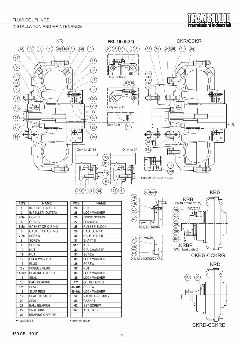
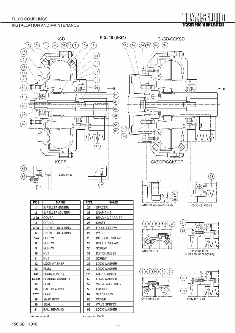
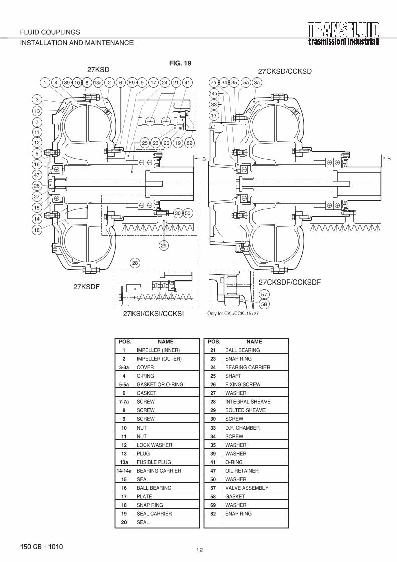
6 - RECOMMENDED SPARE PARTS (FIG. 16 - 17 - 18 - 19)When ordering spare parts, always specify model and spec. nr. marked on external impeller in the positions shown in FIG. 15 or in theopposite side (cover) 27K, 29K and 34K and 46K have got a plate reporting serial nr. too.(With painted couplings the bom number is stamped on the bearing carrier).
6.1 Seal kit for …KR / …KSD items 4-5 (5a for C…/CC…versions)-6-15-20-41 (item 41 only for 27÷46, item 58 only for 15÷46, item 90 only for 46...KR)
6.2 Fusible plug item 13a6.3 Rubber element (for ...KRG only) item 28
N.B.: Code numbers for possible orders are shown on TAB. H
FIG. 14
TAB. K
K...CK..
CCK..
LOCKING TORQUEitem
7-7a 9 10 11-37 30 34 60-70-88 72 78screw
screw Nm screw Nm nut Nm or nut Nm screw Nm screw Nm screw Nm screw Nm screw Nm6
M6 10M5 6 – –
M6 10 – –7-8 M6 10 M7 13
9-11-12M8 24 M8 24
M8 24M8 24 M8 24
13 M10 50
15-17-19 M10 50 M10 50 M10 50 M10 50 – –
21 – – M12 85M14 135
M10 50 – – – –
24M14 135 M14
115 M14 135
27 135M16 205
29 M16 205
34K M14 135 M14 135
34KRD M16 205 M20 400M16 205
– –M6 10
34C e CCK
46 M22 332 M20 400 M20 400 – – M18 283 M22 532 M18 410
TAB. H
6 A 8 BT-A
7B
W(3)– BT-B
8C
X(3) 129 D
– BA BB BC – –
11 EA EB BT-C12KR.. FA FB12KSD GA GB – –
13 HA HB15 KA KB
BT-C
17 LA LBCE CA CB CC BT-D 1219 MA MB 16 BT-P
21 NA NBBT-P 1624 OA OB
27..KR.. PA PB DE BT-T 16 BT-T27..KSD YA YB – DA DB DC – – – –
29 QA QB DE 16 BT-T 16 BT-T34 RA RB 12 BT-I 12 BT-I
46..KR.. ZA ZB EE EA EB EC – – 40 LU...MMD4000(4)
GASKET KIT VITON FUSIBLE PLUG RUBBER BLOCK Item 282395
K.. CK… CCK… N7018(°C)
109 120 140 198BT B3T
N° CODE N° CODEDIM.
(3) For version with metric taper bush(4) Specify the type of material (SN, SP, ...).
150_IT_03
GIUNTI OLEODINAMICI
INSTALLAZIONE AND MANUTENZIONE
7 - O-RINGS AND BEARINGS REPLACEMENT (FIG.16-17-18)
N.B.: To hit the surfaces described in the following, always useplastic hammers.
7.1 Drain oil from coupling by unscrewing the caps (item 13) oncover and delayed fill chamber, and fusible plug item 13a.
7.2 If the fluid coupling is supplied with a delayed fill chamber,remove it after unscrewing item 34.
only for 6 K.. ÷ 34..K...7.3 Unscrew nuts (item 11), insert 2 screw-drivers in the slot
between bearing carrier (item 14) and cover (item 3), and act topush bearing carrier and seal (item 15) out.
7.4 Unscrew bolts (items 8 – 10), tap over the cover (item 3) toremove it. pos. 29 (only for 27KS… remove the snap ring pos.82, the seal carrier pos.19 including seals pos. 20 and 41, snapring pos. 25)
7.5 Remove bearing (item 16) with an extractor, as well as the oilretainer (item 47).
7.6 Remove the snap ring (item 18) and then the impeller (item 1).7.7 Remove screws item 9 and plate washer item 17. Bump on
plane B of the shaft (item 24 for ..KR, item 25 for ..KSD) andslide the bearing carrier (item 23 for ..KR, item 24 for ..KSD)away with the seal (item 20).
only for 46K.. e CCK..7.8 Take away 2 screw pos.7 (diametrally opposite) all bolts pos. 8-
10 or remove the cover pos.3(KR) or pos. 3a (CCKR ) bysuitable extractor using the 2 holes made free of the screwspos.7. The cover will include the seal carrier pos.74 (KR…) or74a (CCKR), seals pos.15 and 90, plate pos.85 (KR) or 85a(CCKR) and screws pos.70.
7.9 Remove the bearing pos.16 or bearing carrier pos.14(KR..) or14a(CCKR..) by extractor.
7.10 Remove the inner impeller (complete with hub pos.75, spacerpos.76, screws pos.2 carrying off the screws pos.9. The impellerwill include the seal carrier pos.19, seals pos.20 and 41, screwspos.60 or 88.
7.11 Remove the outer impeller item 2 taking away the screws item 9;the impeller will include: seal carrier item 19, seals items 20 and41, screws items 60 or 88.
7.12 Remove the snap ring pos.22 and spacer pos.83.7.13 Remove the bearing pos.21, bearing carrier pos.23 and gasket pos.6.7.14 For all couplings (6K.. ÷ 46..K..) when reassembling, proceed
backward replacing the bearings and all seals. Insert sealant(Loctite 518) between the disc plate pos. 17 and the impeller,pos. 2.
N.B. About locking torques of screws, nuts and plugs, pleaserefer to following tables: tab.C1 (pos.59) - tab.C3 (pos. 48-48a-92) - tab. E (pos.13-13a-57) - tab. K (pos. 7-7a-9-10-11-30-34-37-60-70-72-78-88)
FIG. 15
FUSIBLE PLUG
Fusible alloy
120°C
140°C 198°C
Pag.8
328328
783-BA783-BA
10031003 Spec. nr.
Date (month + year)
Production date(week + year)
109°C
150 GB 1010 17-11-2010 9:19 Pagina 4
Solo per 6 62
12
11
7 6
17
9
18
213a3941313 810 7a 34 3533 5a 3a
36
37
38
5
47
8 10
Solo per 6-7-8
2 8 10 1 3
FIG. 16 (6÷34)KR CKR/CCKR
16
26
25
24
22
21
20
23
14
13
15 Solo per 9-11
Solo per CK../CCK..15÷34
CKRG-CCKRG
KRD
..KRBP(Con disco freno)
KRB(Con fascia freno)
KRG
CKRD-CCKRD
30
27
29
31.1 31
CAMERA DI RITARDO
DISCO
GUARNIZIONE O GOMMINO OR
GUARNIZIONE O GOMMINO OR
ANELLO ELASTICO
CUSCINETTO A SFERE
ANELLO DI TENUTA
TAPPO CONICO
DADO
VITE
GOMMINO OR
COPERCHIO
DADO
PORTATENUTA
ANELLO ELASTICO
CUSCINETTO A SFERE
ANELLO DI TENUTA
PORTACUSCINETTO
TAPPO CONICO FUSIBILE
RONDELLA
VITE
VITE
GIRANTE ESTERNA
GIRANTE INTERNA
DENOMINAZIONE
2122
2019
14-14a
16
18
15
4
1213
13a
1110
7-7a
5-5a
89
6
3-3a
POS.
21
DADO
RONDELLA
RONDELLA
VITE
RONDELLA
SCHERMO
393837
26
GOMMINO
VITE
VITE
LINGUETTA
RONDELLA
ALBERO D
SEMIGIUNTO B
SEMIGIUNTO G
FLANGIA G
31.1
343536
33
293031
2827
TIRANTE
ALBERO
2524
VALVOLA COMPLETA5758 GUARNIZIONE
23 PORTACUSCINETTO
POS. DENOMINAZIONE
62 VITE GRANO
67 ADATTATORE
48-48a49-49a
**1747 *
** escluso 6 * solo per 15÷34
14a
58
57
9
4041623
Solo per 27-29 solo per 34
19
60
61
28
30a
Solo per 34KRG
27
48
49
48a 49a
67
48
49
27
Solo per 34CKRG/CCKRG
B
B
623
RONDELLA
FLUID COUPLINGS
INSTALLATION AND MAINTENANCE
9150 GB - 1010
FIG. 16 (6÷34)
POS. NAME1 IMPELLER (INNER)2 IMPELLER (OUTER)
3-3a COVER4 O-RING
5-5a GASKET OR O-RING6 GASKET OR O-RING
7-7a SCREW8 SCREW9 SCREW10 NUT11 NUT12 LOCK WASHER13 PLUG13a FUSIBLE PLUG
14-14a BEARING CARRIER15 SEAL16 BALL BEARING
17** PLATE18 SNAP RING19 SEAL CARRIER20 SEAL21 BALL BEARING22 SNAP RING23 BEARING CARRIER
POS. NAME24 SHAFT25 LOCK WASHER26 FIXING SCREW27 FLANGE G28 RUBBER BLOCK29 HALF JOINT G30 HALF JOINT B31 SHAFT D
31.1 KEY33 D.F. CHAMBER34 SCREW35 LOCK WASHER36 SCREW37 NUT38 LOCK WASHER39 LOCK WASHER47* OIL RETAINER
48-48a SCREW49-49a LOCK WASHER
57 VALVE ASSEMBLY58 GASKET62 SET SCREW67 ADAPTOR
** excluded 6 * only for 15÷34
Only for 6-7-8
Only for 9-11
Only for 6
Only for 27-29 Only for 34
Only for CK../CCK..15÷34
(With brake drum)
(With brake disc)
Only for 34KRG
Only for 34CKRG/CCKRG
150 GB 1010 17-11-2010 9:19 Pagina 7

10
FLUID COUPLINGS
INSTALLATION AND MAINTENANCE
150 GB - 1010
FIG. 17
150 IT 10150 IT_10
46..KR..20 87
78 77
71
70
90
57 58
74
16
75 13 3 1 8 10 39
9
69
6
21
22
23
24
2
13a
4
25
26
85
7
12
72
73
14
76
5
343a 355a 14a33
INSTALLAZIONE AND MANUTENZIONE
46KRFIG. 17
46CCKR
85a
74a
61
60
88
89
41
19
40
83
93
91
4929 28 27
48a
48
49a
92
CCKRG3
CCKRB3 / CCKRBP3
67a
30
30a
15
B
B
FIG. 17
POS. NAME1 IMPELLER (INNER)2 IMPELLER (OUTER)
3-3a COVER4 O-RING
5-5a GASKET OR O-RING6 GASKET OR O-RING7 SCREW8 SCREW9 SCREW10 NUT12 LOCK WASHER13 PLUG13a FUSIBLE PLUG
14-14a BEARING CARRIER15 SEAL16 BALL BEARING19 SEAL CARRIER20 SEAL21 BALL BEARING22 SNAP RING23 BEARING CARRIER24 SHAFT25 FIXING SCREW26 WASHER27 FLANGE G28 RUBBER BLOCK29 HALF JOINT G
30-30a BRAKE DRUM - BRAKE DISC33 D.F. CHAMBER34 SCREW
POS. NAME35 LOCK WASHER39 LOCK WASHER40 PLATE41 O-RING
48-48a SCREW49-49a LOCK WASHER
57 VALVE ASSEMBLY58 GASKET60 SCREW61 LOCK WASHER67a ADAPTOR69 LOCK WASHER70 SCREW71 LOCK WASHER72 SCREW73 LOCK WASHER
74-74a SEAL CARRIER75 HUB76 PLATE77 CLAMPING DEVICE78 SCREW83 SPACER
85-85a PLATE87 PLATE88 SCREW89 LOCK WASHER90 O-RING91 HUB92 SCREW93 LOCK WASHER
150 GB 1010 17-11-2010 9:19 Pagina 2
11
FLUID COUPLINGS
INSTALLATION AND MAINTENANCE
150 GB - 1010
PORTACUSCINETTOPORTACUSCINETTO
DENOMINAZIONEDENOMINAZIONE
CUSCINETTO A SFERECUSCINETTO A SFERE
ANELLO ELASTICOANELLO ELASTICO
PULEGGIA INCORPORATAPULEGGIA INCORPORATA
CAMERA DI RITARDOCAMERA DI RITARDO
PULEGGIA FLANGIATAPULEGGIA FLANGIATA
DISCODISCO
GUARNIZIONE O GOMMINO ORGUARNIZIONE O GOMMINO OR
GUARNIZIONE O GOMMINO ORGUARNIZIONE O GOMMINO OR
TAPPO CONICOTAPPO CONICO
DADODADO
GOMMINO ORGOMMINO OR
COPERCHIOCOPERCHIO
DADODADO
ANELLO ELASTICOANELLO ELASTICO
CUSCINETTO A SFERECUSCINETTO A SFERE
ANELLO DI TENUTAANELLO DI TENUTA
PORTACUSCINETTOPORTACUSCINETTO
TAPPO CONICO FUSIBILETAPPO CONICO FUSIBILE
RONDELLARONDELLA
GIRANTE ESTERNAGIRANTE ESTERNA
GIRANTE INTERNAGIRANTE INTERNA
DENOMINAZIONEDENOMINAZIONE
1010
14-14a14-14a
1818
1616
1515
1313
13a13a
1212
1111
7-7a7-7a
5-5a5-5a
3-3a3-3a
9
8
6
VITEVITE
VITEVITE
VITEVITE
4
2
1
POS.POS.
2929
VITEVITE
SCHERMOSCHERMO
RONDELLARONDELLA
RONDELLARONDELLA
RONDELLARONDELLA
VITEVITE3434
5050
3535
3939
3333
3030
RONDELLARONDELLA
TIRANTETIRANTE
ALBEROALBERO
DISTANZIALEDISTANZIALE
2424
2727
2828
2525
2626
2323
2222
2121
POS.POS.
ANELLO DI TENUTAANELLO DI TENUTA2020
VALVOLA COMPLETAVALVOLA COMPLETA
GUARNIZIONEGUARNIZIONE
5757
5858
6262 VITE GRANOVITE GRANO
6565
1717 **
4747 *
* escluso 6escluso 6 * solo per 15÷34solo per 15÷34
RONDELLARONDELLA6969
MOLLA ONDULATAMOLLA ONDULATA
COPERCHIETTOCOPERCHIETTO
6666
*
KSD
Solo per 6-7-8
2 8 10 1
Solo per 9-11
8 10
Solo per 17-21
22
69
Solo per CK../CCK..15÷27
58
57
7a 34 3533 5a 3a
13
14a
12
11
7
16 24
6
17
9
18
213a3941313 810
15
5
47
26
27
14
25
23
21
20
62
66
65 Solo per 6
FIG. 18 (6÷24)
150 IT 11150 IT_11
28
KSI/CKSI/CCKSI
Solo per 19-24(17-21 solo appl. gravose)
69
21213
3
CKSD/CCKSD
KSDF CKSDF/CCKSDF
50
30
29
B B
FIG. 18 (6÷24)
POS. NAME
1 IMPELLER (INNER)
2 IMPELLER (OUTER)
3-3a COVER
4 O-RING
5-5a GASKET OR O-RING
6 GASKET OR O-RING
7-7a SCREW
8 SCREW
9 SCREW
10 NUT
11 NUT
12 LOCK WASHER
13 PLUG
13a FUSIBLE PLUG
14-14a BEARING CARRIER
15 SEAL
16 BALL BEARING
17*** PLATE
18 SNAP RING
20 SEAL
21 BALL BEARING
POS. NAME
22 SPACER
23 SNAP RING
24 BEARING CARRIER
25 SHAFT
26 FIXING SCREW
27 WASHER
28 INTEGRAL SHEAVE
29 BOLTED SHEAVE
30 SCREW
33 D.F. CHAMBER
34 SCREW
35 LOCK WASHER
39 LOCK WASHER
47** OIL RETAINER
50 LOCK WASHER
57 VALVE ASSEMBLY
58 GASKET
62 SET SCREW
65 COVER
66 WAVE SPRING
69 LOCK WASHER
*** excluded 6 ** only for 15÷34
Only for CK../CCK..15÷27
Only for 9-11
Only for 6
Only for 6-7-8 Only for 17-21
Only for 19-24(17-21 only for heavy duty)
150 GB 1010 17-11-2010 9:19 Pagina 11
12
FLUID COUPLINGS
INSTALLATION AND MAINTENANCE
150 GB - 1010
27KSD
27KSDF
27CKSD/CCKSDFIG. 19 (27)
27CKSDF/CCKSDF
11
7
12
13
47
15
16
27
26
5
14
39 213a1 10
3
4
18
69 9
27KSI/CKSI/CCKSI
17
23 20 19
24
25
4121
30 50
28
29
Solo per CK../CCK..15÷27
58
57
34 5a
14a
35
13
3a7a
33
PORTACUSCINETTO
DENOMINAZIONE
CUSCINETTO A SFERE
ANELLO ELASTICO
PULEGGIA INCORPORATA
CAMERA DI RITARDO
PULEGGIA FLANGIATA
DISCO
TAPPO CONICO
DADO
GOMMINO OR
COPERCHIO
DADO
ANELLO ELASTICO
CUSCINETTO A SFERE
ANELLO DI TENUTA
PORTACUSCINETTO
TAPPO CONICO FUSIBILE
RONDELLA
GIRANTE ESTERNA
GIRANTE INTERNA
10
14-14a
18
16
15
13
13a
12
11
7-7a
5-5a
3-3a
9
8
6
VITE
VITE
VITE
4
2
1
POS.
29
VITE
SCHERMO
RONDELLA
RONDELLA
RONDELLA
VITE34
50
35
39
33
30
RONDELLA
TIRANTE
ALBERO
24
27
28
25
26
23
21
POS.
ANELLO DI TENUTA20
VALVOLA COMPLETA
GUARNIZIONE
57
58
17
47
82 ANELLO ELASTICO
GOMMINO OR
GUARNIZIONE
PORTATENUTA19
GOMMINO OR41
82
6
B B
8
DENOMINAZIONEDENOMINAZIONE
FIG. 19
POS. NAME
1 IMPELLER (INNER)
2 IMPELLER (OUTER)
3-3a COVER
4 O-RING
5-5a GASKET OR O-RING
6 GASKET
7-7a SCREW
8 SCREW
9 SCREW
10 NUT
11 NUT
12 LOCK WASHER
13 PLUG
13a FUSIBLE PLUG
14-14a BEARING CARRIER
15 SEAL
16 BALL BEARING
17 PLATE
18 SNAP RING
19 SEAL CARRIER
20 SEAL
POS. NAME
21 BALL BEARING
23 SNAP RING
24 BEARING CARRIER
25 SHAFT
26 FIXING SCREW
27 WASHER
28 INTEGRAL SHEAVE
29 BOLTED SHEAVE
30 SCREW
33 D.F. CHAMBER
34 SCREW
35 WASHER
39 WASHER
41 O-RING
47 OIL RETAINER
50 WASHER
57 VALVE ASSEMBLY
58 GASKET
69 WASHER
82 SNAP RING
Only for CK../CCK..15÷27
150 GB 1010 17-11-2010 9:19 Pagina 12

CKRGW-CCKRGW
KRDWKRGW
CKRDW-CCKRDW
KRW
CKRW/CCKRW
(a)(b)
B
PASTASIGILLANTE (a) solo per 34
79
80
78
9a 69
grasso
grasso
81
69
79
9a
78
80
(a) solo per 27-29
grasso grasso80
(b) solo per 34
grasso
97
95
96
94
81(tipo Loctite 518)
13
FLUID COUPLINGS
INSTALLATION AND MAINTENANCE
150 GB - 1010
FIG. 20 (13÷34)
The fluid couplings serie... KR...W are working by using mixed distilled water instead of mineral oil. The bearings are greasedfor life by ROCOL SAPPHIRE AQUA 2 grease or equivalent.The installation and maintenance manual 150 GB is also valid for fluid couplings serie ...KR...W, except the table D (page 4)concerning the working fluid (water instead of oil).The water is mixed to a special liquid (AGIP ECOFREEZER or equivalent) on the basis of inhibited propilic glicole which is normallyused in a closed cooling circuit of internal combustion engines: it is BIODEGRADABLE – ANTIFOAM - UNFLAMABLE. Appropriatelymixed (with 50% water and 50% special liquid) it increases the boiling point and reduces the freezing point (see table L).The fluid couplings ...KR...W are supplied with fusible plug at 109°C .It is recommended to check periodically the fluid level and adjust it, if necessary, according to instructions given on p. 4.For replacement of seals and bearings, see item 7 on page 8 considering the below variations:7.5 Remove the bearing pos.16 and seal pos.817.7 Remove the screws pos. 9a, the retainer pos.79, gasket and seal pos.78 and 807.8 When reassembling, proceed backward replacing the bearings and all seals, putting grease ROCOL SAPPHIRE AQUA 2 (or
equivalent) between bearings and seals as indicated in fig. (a) and (b).
TAB. L
Volume Boiling Freezing% point point
50 104°C -33°C60 106°C -48°C80 118°C -54°C100 160°C -60°C
TAB. M TAB. N
15-17-19 M10 50 – –
21-24M14 135
– –
27-29 – –
34 M16 205 M8 24
POS. NAME
9a SCREW
69 LOCK WASHER
78 GASKET
79 SEAL CARRIER
80 SEAL
POS. NAME
81 SEAL
94 SEAL CARRIER
95 SCREW
96 LOCK WASHER
97 O-RING
Locking torquePos. 9a Pos. 96
Screw Nm Screw NmDIM
only for 27-29 only for 34
grease
grease
grease grease grease
SEALANT(type Loctite 518) only for 34
150 GB 1010 17-11-2010 11:04 Pagina 13

14
FLUID COUPLINGS
INSTALLATION AND MAINTENANCE
150 GB - 1010
ADDITIONAL RULES FOR USE IN HAZARDOUS AREAS OF FLUID COUPLINGS
1 - INSTALLATIONRadial misaligment (R), must be measured with a dial indicator as shown on Fig. 4 of the manual.Misalignment values stated on Tab. C - C1 and C2 are subject to the following limitations:radial misalignment (R) : max 0,2 mmangular misalignment (A1-A2) : reduce indicated valued by 50%distance between coupling halves (k) : dimensional tolerance is ± 0,5 mm
2 - OPERATION
- After first start-up verify the tightening of the drive and driven machines screws, however it’srecommended also to check the tightening of them periodically.
- Check again misalignment according to the manual: paragraph 1.8 (KRG) - 1.17 (KRM) - 1.22 (KRG3)
It is recommended:- to use a strong coupling guard, preferably in “no-spark” material which is equipped with openings for
ventilation. The openings must be smaller than the smallest nut installed on the fluid coupling in orderto avoid emission of metallic parts caused by centrifugation of the rotating coupling which may causesparks.
- a careful cleaning of surfaces of the fluid coupling before every system start.- to check if aluminium material of the fluid coupling is compatible with the working atmosphere (in case
of uncertainty please contact TRANSFLUID).- to use drive belts suitable for the pulley (if present) for potentially explosive atmospheres.- the correct installation and proper use of joints alignment (see documents TF6429 - TF6429A).- a periodic review and possible replacement of the rubber elements of TRANSFLUID elastic couplings.
For BT and BM models, check that the machining of holes in the joints were carried out byTRANSFLUID.
Verify every 6 months:- the condition of the O-rings and Viton oil seals. Replace them immediately if they are broken or show
signs of wear.- the wear conditions of the rubber elements (if present), that the rotational gap is always lower than 2°
(as described in paragraph 3.3 of the manual).- there are no oil leaks. If leaks are found, overhaul the fluid coupling immediately.
3 - ELECTRIC DEVICE
Check every 6 months the functionality of the electric device (if installed).
4 - MAINTENANCE
Any overhaul and repair of the fluid coupling must be carried out by an official TRANSFLUIDservice centre that will document modifications performed.
150 GB 1010 17-11-2010 9:19 Pagina 14

TRANSFLUID s.r.l. ■ Via Guido Rossa, 4 ■ 21013 Gallarate (VA) Italy ■ Tel. +39-0331.28421 ■ Fax +39-0331.2842911 ■ e-mail: [email protected] ■ www.transfluid.eu
1010 - 150 GB
BASIC GUARANTEE TERMS AND CONDITIONS
1) PreambleTRANSFLUID guarantees that at the time of dispatch, its productscomply with the specifications published in its catalogues ortechnical documents, which were valid at the time of dispatch,and that the products are free from defects in material andworkmanship. These terms of guarantee substitute all otherguarantees, including legal, expressed or implicit guarantees,including but not limited to, guarantees of saleability andsuitability for a particular use (and any other implicit guaranteearising during the course of the services, negotiations orcommercial use). Except in the event of serious negligence andfraud, under no circumstances will TRANSFLUID be held liable fordirect, indirect, consequential, fortuitous or extra contractualdamage based upon claims for compensation by the Buyer forviolation of the guarantee, contract or objective responsibility.Under no circumstances can the compensation by TRANSFLUIDexceed the amount paid by the Buyer for the product supplied byTRANSFLUID.
2) Duration and limits of the guaranteea) The duration of the guarantee is equal to eighteen (18)
months from the time the product supplied by TRANSFLUIDis commissioned, and nonetheless, no more than twenty-four(24) months from the date of dispatch of the original productfrom TRANSFLUID’s plant.
b) Product that are not used and stored for a long period must bekept and handled in keeping with the guidelines, which areavailable upon request, drawn up by TRANSFLUID accordingto product type.
c) The wear or tear of parts, which is particularly due toconditions of use (tension of the belts, environmentalconditions, unforeseen knocks and overloading), or to thesensitivity of the operator (use within the approved limits) or toexternal circumstances (jamming of the machine), is notcovered by the guarantee if these parts have been used (arenot new), unless the Buyer can clearly prove themanufacturing defect, which is ascribable to TRANSFLUID.Typical parts subject to wear or tear include:- Filters, seals and gaskets- Springs, screws, plugs- Switches and fuses- Material and friction surfaces- Belts and chains- Lubricants in general
d) Installation and maintenance of TRANSFLUID products mustbe carried out following the installation, use and maintenancemanual, which is always supplied with each product.
e) With regard to the supply of loose/disassembled parts, theguarantee solely and exclusively covers faults of thecomponents themselves, related to the material ormechanical workmanship carried out by TRANSFLUID.
f) The guarantee is no longer valid when:
b) Excluded from the guarantee and remaining at the Buyer’sexpense are the costs resulting from:- Removal of the TRANSFLUID product from the machinery
onto which it is fitted, and recommissioning;- Suitable packing and charges resulting from the return
transport of the material;- Restoration of lubricants in general, piping, sound proof
canopies, guards, etc.- All other costs not expressly approved in writing by
TRANSFLUID.c) The Buyer can request the support of a specialised technician
to disassemble/re-install/recommission the product bysending a standard purchase order. TRANSFLUID will invoicethe work, applying the current ASSIOT rates (ItalianAssociation of Gears and Transmission ElementsManufacturers, a member of EUROTRANS).
d) TRANSFLUID cannot be held liable for lost or reduced profit,costs for replaced machinery, still machinery, damage toequipment or property caused by failure of its products.
4) Conditions for requesting services under guarantee a) If the Buyer intends to take advantage of the guarantee, he
must inform TRANSFLUID in writing within 7 (seven) days ofdiscovering a fault, stating:- Product description;- Series number (where foreseen), specification number or
article code;- Reference to the date and document of purchase or delivery;- Reasonable proof that the fault falls within the conditions of
guarantee, together with a detailed description of theirregularity or failure and where possible, supported byphotographs.In the event of failure after commissioning the product, thefollowing must also be communicated:
- Type of application;- Power and engine rpm (stating also the make and model for
endothermic engines);- Diameter, type, number of races and position of pulley (if
foreseen by the application);- Hours of operation.
b) TRANSFLUID will indicate whether the product must bedelivered or sent free port to an authorised centre or directlyto its own plant depending on the product concerned, thefailure indicated and the urgency of the intervention.
c) On receiving the product, TRANSFLUID or the authoriseddistributor will carry out a thorough analysis; if the product isdeemed to be covered by the guarantee:- TRANSFLUID will repair or replace the parts needed to
restore full and safe working at no cost;If the product is NOT deemed to be covered by the guarantee,TRANSFLUID:- will send a technical report explaining its decision;- will draw up an estimate for the repair;- will carry out the repair upon receipt of the order from the
Buyer.d) The repaired products will be returned to the Buyer freight
collect, by the same means of transport that was used for thearrival (unless stated otherwise).
e) Should the Buyer decide not to accept the estimate for therepair, he must communicate his decision in writing, explicitlyasking for the parts to be scrapped or returned; the parts willbe sent in their current state.
- the product is used exceeding the limits stated in thecatalogues or installation manuals, or in applications that arenot approved by TRANSFLUID;
- breakage results from abuse, negligence, omission orinadequate maintenance, failed connection or control of theprotection devices or as a result of accidents;
- the product is modified or disassembled withoutTRANSFLUID’S written approval.
3) Services included/excluded in the guaranteea) In TRANSFLUID’S final decision, products or components,
whose faults are covered by the guarantee, will be repaired orreplaced at no extra cost, with the exception of thesubsequent points. The replaced parts will be covered fromthe remaining period of the original guarantee, which stays inforce for the product initially supplied (a new guarantee periodwill therefore not come into effect).
copertina 150 GB 17-11-2010 11:22 Pagina 1