Fluid Control Express - ESMA Industrial Enterprisesesmagroup.com/products/Automation/Solenoid...
30
Fluid Control Express Modular Solenoid Valves Shipped Next Day
Transcript of Fluid Control Express - ESMA Industrial Enterprisesesmagroup.com/products/Automation/Solenoid...

Fluid Control ExpressModular Solenoid Valves Shipped Next Day

AEROSPACEKey Markets• Aircraft engines• Business & general aviation• Commercial transports• Land-based weapons systems• Military aircraft• Missiles & launch vehicles• Regional transports• Unmanned aerial vehicles
Key Products• Flight control systems & components• Fluid conveyance systems• Fluid metering delivery & atomization devices• Fuel systems & components• Hydraulic systems & components• Inert nitrogen generating systems• Pneumatic systems & components• Wheels & brakes
ELECTROMECHANICALKey Markets• Aerospace• Factory automation• Food & beverage• Life science & medical• Machine tools• Packaging machinery• Paper machinery• Plastics machinery & converting• Primary metals• Semiconductor & electronics• Textile• Wire & cable
Key Products• AC/DC drives & systems• Electric actuators• Controllers• Gantryrobots• Gearheads• Human machine interfaces• Industrial PCs• Inverters• Linear motors, slides and stages• Precision stages• Stepper motors• Servo motors, drives & controls• Structural extrusions
HYDRAULICSKey Markets• Aerospace• Aerial lift• Agriculture• Construction machinery• Forestry• Industrial machinery• Mining• Oil & gas• Power generation & energy• Truck hydraulics
Key Products• Diagnostic equipment• Hydraulic cylinders & accumulators• Hydraulic motors & pumps• Hydraulic systems• Hydraulic valves & controls• Power take-offs • Rubber & thermoplastic hose & couplings• Tube fittings & adapters• Quick disconnects
FILTRATIONKey Markets• Food & beverage• Industrial machinery• Life sciences• Marine• Mobile equipment• Oil & gas• Power generation• Process• Transportation
Key Products• Analytical gas generators• Compressed air & gas filters• Condition monitoring• Engine air, fuel & oil filtration & systems• Hydraulic, lubrication & coolant filters• Process, chemical, water & microfiltration filters• Nitrogen, hydrogen & zero air generators
SEALING & SHIELDINGKey Markets• Aerospace• Chemical processing• Consumer• Energy, oil & gas• Fluid power• Generalindustrial• Information technology• Life sciences• Military• Semiconductor• Telecommunications• Transportation
Key Products• Dynamic seals• Elastomeric o-rings • EMI shielding• Extruded & precision-cut, fabricated elastomeric seals• Homogeneous & inserted elastomeric shapes • High temperature metal seals• Metal & plastic retained
composite seals• Thermal management
FLUID & GAS HANDLINGKey Markets• Aerospace• Agriculture• Bulk chemical handling• Construction machinery• Food & beverage• Fuel & gas delivery• Industrial machinery• Mobile• Oil & gas• Transportation• Welding
Key Products• Brass fittings & valves• Diagnostic equipment • Fluid conveyance systems• Industrial hose• PTFE & PFA hose, tubing & plastic fittings• Rubber & thermoplastic hose & couplings• Tube fittings & adapters• Quick disconnects
PNEUMATICSKey Markets• Aerospace• Conveyor & material handling• Factory automation• Food & beverage• Life science & medical• Machine tools• Packaging machinery• Transportation & automotive
Key Products• Air preparation• Compact cylinders• Field bus valve systems• Grippers• Guidedcylinders• Manifolds• Miniature fluidics• Pneumatic accessories• Pneumatic actuators & grippers • Pneumatic valves and controls• Rodless cylinders• Rotary actuators• Tie rod cylinders• Vacuum generators, cups &
sensors
PROCESS CONTROLKey Markets• Chemical & refining• Food, beverage & dairy• Medical & dental• Microelectronics• Oil & gas• Power generation
Key Products• Analytical sample conditioning products & systems• Fluoropolymer chemical delivery fittings, valves & pumps• High purity gas delivery fittings, valves & regulators• Instrumentation fittings,
valves & regulators• Medium pressure
fittings & valves• Process control manifolds
Parker’s Motion & Control TechnologiesAt Parker, we’re guided by
a relentless drive to help
our customers become more
productive and achieve
higher levels of profitabil-
ity by engineering the best
systems for their require-
ments. It means looking at
customer applications from
many angles to find new
ways to create value. What-
ever the motion and control
technology need, Parker has
the experience, breadth of
product and global reach
to consistently deliver. No
company knows more about
motion and control technol-
ogy than Parker. For further
info call 1 800 C-Parker
(1 800 272 7537).
CLIMATE CONTROLKey Markets• Agriculture• Air conditioning• Food, beverage & dairy• Lifesciences&medical• Precision cooling• Processing• Transportation
Key Products• CO2 controls• Electronic controllers• Filter driers• Hand shut-off valves• Hose & fittings• Pressure regulating valves• Refrigerant distributors• Safety relief valves• Solenoid valves• Thermostatic expansion valves

PARKER FLUID CONTROL DIVISIONOur HistoryFor over 60 years, Parker Hannifin, as a global leader in motion and control technologies, has been a lead innovator and supplier in the solenoid valve industry for a variety of installations and applications. Our valves are supplied by Parker under the Jackes Evans, Skinner® and Gold Ring™ trade names and are capable of on/off control for a wide variety of liquids and gases.
MarketsOur products and solutions are typically designed for Process Control, Transportation, Commercial Equipment, Cooling & Climate Control, Food & Beverage and Industrial & Automation markets.
Features and BenefitsWith our modular concept of valves, coils and electrical components, we can help you achieve greater flexibility for your inventory and work in process with limited stock.
Who We AreWe are the Fluid Control Division and are part of the Climate and Industrial Control Group of Parker Hannifin Corporation. Our primary product offerings are solenoid valves and systems used for the control of liquid and gas medias.
With both the Skinner® and Gold Ring™ product lines, we are able to tackle a wide variety of tough applications demanding high performance and long life, while also providing the flexibility to service your MRO and OEM replacements.
Where We AreThe Fluid Control Division of North America (FCD) is headquartered in New Britain, CT. Along with Customer Service, Product Engineering, Research and Development, Marketing, Application Support, and Product Management, we manufacture the Skinner® Valve product line at this location.
In our Madison, MS, Facility, we manufacture our core Gold Ring™ valve offering and support a full line of specialty valves, value added assemblies, and manifolds.
The Fluid Control Division of Parker Hannifin Corporation has a global manufacturing and sales presence through our European Headquarters and manufacturing in Geneva, Switzerland, and Gessate, Italy, and also through manufacturing locations in Korea, China, and Brazil.
Fluid Control Division Headquarters, New Britain, CT. Fluid Control Division Facility, Madison, MS.
i

Parker Hannifin CorporationFluid Control Division1 800 825 8305 www.parker.com/[email protected]
Navigation: 5 Easy Steps
The pressure vessel and solenoid coil are boxed and shipped separately. Quantities of 10 pieces or less will ship next day. Quantities of 11-50 pieces will ship in 5 working days.Quantities greater than 51 pieces may be scheduled.
Flip out the tab attached to the back cover to reveal Coil Chart.The stated wattage represents a nominal value. The actual wattage may vary depending on coil/pressure vessel selection.
HOW TO USE THE CATALOG
1. Choose your pressure vessel2. Choose your coil reference number3. Find your coil reference number on the Coil Chart4. Place order for pressure vessel and coil as separate items.5. Request distributor to place order via PHConnect.
Please refer to the coil chart number reference within the catalog to find the Fluid Control Express coil.
Please refer to the coil chart number within the catalog to find the correct coil in the chart below.
COILS
Gold RingTM Voltage 1/2” NPT Conduit* DIN43650A/ISO4400
CHART 16 watts, Class F
24/60120/60-110/50240/60-220/50
AF4C01AF4C05AF4C15
-AFPH05AFPH15
Gold RingTM Voltage 1/2” NPT Conduit* DIN43650A/ISO4400
CHART 411 watts, Class F
24/60120/60-110/50240/60-220/50
CF4C01CF4C05CF4C15
-CFPH05CFPH15
CHART 516 watts, Class F
24/60120/60-110/50240/60-220/50
DF4C01DF4C05DF4C15
-DFPH05DFPH15
CHART 611.5 watts, Class F
12VDC24VDC
3F4C753F4C80
3FPH753FPH80
* 18” Lead Wires, Nema 1, 2, 3, 4, 4X** Hazardous location coil approval: Class I, Div I & II, Groups A, B, C, D; Class II, Div I & II, Groups E, F, G; Class III, Div I.*** 8.5 Watt For 2 - Way Normally Closed AC
Skinner® Voltage 1/2” NPT Conduit* DIN43650A/ISO4400 18” Leads
CHART 9AC 10 watts***
DC 8 wattsClass F
24/60120/60-110/50240/60-220/50
12VDC24VDC
C4EC4FC4GC4AC4B
-----
B4EB4FB4GB4AB4B
CHART 9AC 10 watts***
DC 8 wattsClass H
24/60120/60-110/50240/60-220/50
12VDC24VDC
-----
D6ED6FD6GD6AD6B
-----
Skinner® Voltage 1/2” NPT Conduit* DIN 43650A/ISO4400 Hazardous**
CHART 710 watts, Class F
24/60120/60-110/50240/60-220/50
12VDC24VDC
C111B2 C111P3C111Q3C111C1C111C2
D100B2D100P3D100Q3D100C1D100C2
-H111P3H111Q3H111C1H111C2
CHART 710 watts, Class H
120/60-110/50240/60-220/50
12VDC24VDC
C222P3 C222Q3C222C1C222C2
----
H222P3H222Q3
-H222C2
CHART 822 watts, Class H
120/60-110/5012VDC24 VDC
C322P3C322C1C322C2
---
H322P3H322C1H322C2
1 2
3
Images shown in this catalog are representative only.
HOW TO USE THE CATALOG
ii
Parker Hannifin CorporationFluid Control Division1 800 825 8305 www.parker.com/[email protected]
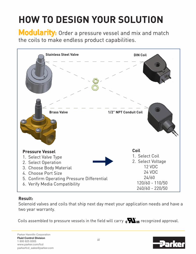
Modularity: Order a pressure vessel and mix and match the coils to make endless product capabilities.
HOW TO DESIGN YOUR SOLUTION
DIN Coil
1/2” NPT Conduit Coil
Stainless Steel Valve
Brass Valve
Pressure Vessel1. Select Valve Type2. Select Operation3. Choose Body Material4. Choose Port Size5. Confirm Operating Pressure Differential6. Verify Media Compatibility
Coil1. Select Coil2. Select Voltage 12 VDC 24 VDC 24/60 120/60 - 110/50 240/60 - 220/50
Coils assembled to pressure vessels in the field will carry recognized approval.
Result: Solenoid valves and coils that ship next day meet your application needs and have a two year warranty.
iii

Parker Hannifin CorporationFluid Control Division1 800 825 8305 www.parker.com/[email protected]
iv
Together, we cancontrol virtually any media, in any application, under any condition.
Process Control• Valve Actuation • Oil & Gas• Chemical Processing• Pharmaceutical
Transportation• Trucks • Trains• Bus & Coach• Marine• Agriculture
Industrial & Automation• Compressors • Blow Molding• Textile
Cooling & Climate Control• Water Dispensing • Cooling Systems• Irrigation
Commercial Equipment• Medical Equipment• Water Purification• Sterilizers• Welding
Food & Beverage• Coffee Machines • Sparkling Water• Beverage Dispensing• Water Dispensing

Parker Hannifin CorporationFluid Control Division1 800 825 8305 www.parker.com/[email protected]
2 Way Section................................................................................................ 1-8 2 Way Normally Closed Direct Acting 1-2 2 Way Normally Open Direct Acting 3 2 Way Normally Closed Steam and Hot Water 4 2 Way Normally Closed Pilot-Operated 5-7 2 Way Normally Open Pilot-Operated 8
3 Way Section................................................................................................ 9-12 3 Way Normally Closed Direct Acting 9 3 Way Normally Open Direct Acting 10 3 Way Multipurpose Direct Acting 11 3 Way Normally Closed Pilot-Operated 12
4 Way Section................................................................................................ 13 4 Way Single Solenoid Internally Pilot-Operated 13 Repair Kits..................................................................................................... 14
Parker - FCD Safety Guide....................................................................... 15-16
Offer of Sale................................................................................................... 17
Favorites......................................................................................................... 18
Phone Numbers........................................................................................... 19
Notes..................................................................................................Inside Back Cover
Coils..................................................................................Flip Out Tab On Back Cover
For complete valve specifications including materials of construction, consultthe General Purpose Solenoid Valves Catalog FCDFL0911, available for download at www.parker.com/fcd, under Literature.
TABLE OF CONTENTS
v

2-W
ay
Parker Hannifin CorporationFluid Control Division1 800 825 8305 www.parker.com/[email protected]
2-Way Direct Acting - Normally Closed - Brass
Port Size NPT
Orifice Size in.
Flow Factor
Cv
Operating Pressure Differential (MOPD) PSI
Watt
Max. Media Temp.
°F SealPressure Vessel
NumberCoil
ChartMin.
Air, Inert Gas Water
Light Oil
AC VOLTAGE
1/8 1/8 .31 0 365 365 365 10 165 PCTFE 7121KBN1NF00 7
1/4 1/8 .31 0 365 365 365 10 165 PCTFE 7121KBN2NF00 7
1/4 1/8 .31 0 145 145 145 10 185 FKM 7121KBN2NV00 7
1/4 5/32 .52 0 120 120 120 10 185 FKM 7121KBN2QV00 7
1/4 13/64 .76 0 80 80 80 10 185 FKM 7121KBN2SV00 7
1/2 7/16 2.5 0 17.5 17.5 17.5 10 185 FKM 7121KBN44V00 7
DC VOLTAGE
1/8 1/8 .31 0 125 125 125 10 165 PCTFE 7121KBN1NF00 7
1/4 1/8 .31 0 125 125 125 10 165 PCTFE 7121KBN2NF00 7
1/4 1/8 .31 0 125 125 125 10 185 FKM 7121KBN2NV00 7
1/4 5/32 .52 0 60 60 60 10 185 FKM 7121KBN2QV00 7
1/4 13/64 .76 0 30 30 30 10 185 FKM 7121KBN2SV00 7
1/2 7/16 2.5 0 5 5 5 10 185 FKM 7121KBN44V00 7
1

2-W
ay
Parker Hannifin CorporationFluid Control Division1 800 825 8305 www.parker.com/[email protected]
2-Way Direct Acting - Normally Closed - Stainless Steel
Port Size NPT
Orifice Size in.
Flow Factor
Cv
Operating Pressure Differential (MOPD) PSI
Watt
Max. Media Temp.
°F SealPressure Vessel
NumberCoil
ChartMin.
Air, Inert Gas Water
Light Oil
AC VOLTAGE
1/8 1/8 .28 0 200 200 200 10 185 NBR 71215SN1MN00 7
1/8 3/64 .06 0 950 950 950 8.5 240 FKM 20CC02EV4 9
1/8 1/16 .10 0 625 625 625 8.5 240 FKM 20CC02GV4 9
1/8 3/32 .22 0 320 320 320 8.5 240 FKM 20CC02LV4 9
1/8 7/64 .28 0 245 245 245 8.5 240 FKM 20CC02MV4 9
1/8 1/8 .32 0 175 175 175 8.5 240 FKM 20CC02PV4 9
1/8 5/32 .38 0 100 100 100 8.5 240 FKM 20CC02QV4 9
1/4 1/32 .02 0 3000 3000 3000 10 185 Nylon 71216SN2BL00 7
1/4 3/64 .037 0 1500 1500 1500 10 185 PTFE 71216SN2FU00 7
1/4 3/64 .06 0 450 450 450 10 185 NBR 71215SN2EN00 7
1/4 1/16 .10 0 350 350 350 10 185 NBR 71215SN2GN00 7
1/4 3/32 .18 0 275 275 275 10 185 NBR 71215SN2KN00 7
1/4 1/8 .28 0 200 200 200 10 185 NBR 71215SN2MN00 7
1/4 5/32 .40 0 110 110 110 10 185 NBR 71215SN2QN00 7
1/4 3/16 .50 0 80 80 80 10 185 NBR 71215SN2SN00 7
1/4 1/4 .75 0 40 40 40 10 185 NBR 71215SN2VN00 7
1/4 5/16 1.1 0 20 20 20 10 185 NBR 71215SN21N00 7
3/8 3/8 2.0 0 6 6 6 10 185 NBR 71215SN33N00 7
DC VOLTAGE
1/8 1/8 .28 0 150 150 150 10 185 NBR 71215SN1MN00 7
1/8 3/64 .06 0 390 390 390 8 240 FKM 20CC02EV4 9
1/8 1/16 .10 0 255 255 255 8 240 FKM 20CC02GV4 9
1/8 3/32 .22 0 130 130 130 8 240 FKM 20CC02LV4 9
1/8 7/64 .28 0 100 100 100 8 240 FKM 20CC02MV4 9
1/8 1/8 .32 0 60 60 60 8 240 FKM 20CC02PV4 9
1/8 5/32 .38 0 30 30 30 8 240 FKM 20CC02QV4 9
1/4 3/64 .06 0 450 450 450 10 185 NBR 71215SN2EN00 7
1/4 1/32 .02 0 2500 2500 2500 10 185 Nylon 71216SN2BL00 7
1/4 1/32 .02 0 3000 3000 3000 22 185 Nylon 71216SN2BL00 8
1/4 3/64 .037 0 1000 1000 1000 10 185 PTFE 71216SN2FU00 7
1/4 3/64 .037 0 1500 1500 1500 22 185 PTFE 71216SN2FU00 8
1/4 1/16 .10 0 350 350 350 10 185 NBR 71215SN2GN00 7
1/4 3/32 .18 0 275 275 275 10 185 NBR 71215SN2KN00 7
1/4 1/8 .28 0 150 150 150 10 185 NBR 71215SN2MN00 7
2

2-W
ay
Parker Hannifin CorporationFluid Control Division1 800 825 8305 www.parker.com/[email protected]
2-Way Direct Acting - Normally Open - Brass
Port Size NPT
Orifice Size in.
Flow Factor
Cv
Operating Pressure Differential (MOPD) PSI
Watt
Max. Media Temp.
°F SealPressure Vessel
NumberCoil
ChartMin.
Air, Inert Gas Water
Light Oil
AC VOLTAGE
1/4 3/32 .17 0 300 250 230 11 180 NBR 04F20O1106ACF 4
1/4 3/32 .21 0 175 175 175 10 165 PCTFE 7122KBN2LF00 7
1/4 9/32 .96 0 30 25 20 11 180 NBR 04F20O2118ACF 4
DC VOLTAGE
1/4 3/32 .21 0 175 175 175 10 165 PCTFE 7122KBN2LF00 7
2-Way Direct Acting - Normally Open - Stainless Steel
Port Size NPT
Orifice Size in.
Flow Factor
Cv
Operating Pressure Differential (MOPD) PSI
Watt
Max. Media Temp.
°F SealPressure Vessel
NumberCoil
ChartMin.
Air, Inert Gas Water
Light Oil
AC VOLTAGE
1/8 3/64 .06 0 230 230 230 10 240 FKM 20CF02EV4 9
1/8 3/32 .20 0 80 80 80 10 240 FKM 20CF02LV4 9
1/4 3/32 .15 0 250 250 250 10 185 NBR 71295SN2KNJ1 7
DC VOLTAGE
1/8 3/64 .06 0 230 230 230 8 240 FKM 20CF02EV4 9
1/8 3/32 .20 0 80 80 80 8 240 FKM 20CF02LV4 9
1/4 3/32 .15 0 250 250 250 10 185 NBR 71295SN2KNJ1 7
3

2-W
ay
Parker Hannifin CorporationFluid Control Division1 800 825 8305 www.parker.com/[email protected]
2-Way Normally Closed Steam and Hot Water - Brass
Port Size NPT
Orifice Size in.
Flow Factor
Cv
Operating Pressure Differential (MOPD) PSI
Watt
Max. Media Temp.
°F SealPressure Vessel
NumberCoil
ChartMin.
Hot Water (PSI)
Steam(PSI)
Lt. Oil300 SSU
(PSI)AC VOLTAGE
1/2 5/8 4.0 0 150 50 - 11 300 EPDM 08FS3C2340ACF 4
1/2 1/2 3.6 1 - 125 - 11 353 PTFE 08FS5C2432ACH Below
3/4 3/4 5.0 0 150 50 - 11 300 EPDM 12FS3C2348ACF 4
3/4 5/8 5.0 0 100 - - 10 210 EPDM 72218BN5VE00 7
3/4 3/4 7.4 1 - 125 - 11 353 PTFE 12FS5C2448ACH Below
1 1 8.8 1 - 125 - 11 353 PTFE 16FS5C2464ACH Below
1 1 11.7 0 150 - - 10 210 EPDM 7221GBN64E00 7
1 1/2 1 1/2 22.5 5 150 50 - 6 300 EPDM 24FS4C2380AAF 1
Gold Ring TM Voltage 1/2” NPT Conduit*
11 WattsClass H
24/60120/60240/60
CH4C01CH4C05CH4C15
* 18” Lead Wires, Nema 1, 2, 3, 4, 4X
4

2-W
ay
Parker Hannifin CorporationFluid Control Division1 800 825 8305 www.parker.com/[email protected]
2-Way Internally Pilot Operated & Direct Lift - Normally Closed - Brass
Port Size NPT
Orifice Size in.
Flow Factor
Cv
Operating Pressure Differential (MOPD) PSI
Watt
Max. Media Temp.
°F SealPressure Vessel
NumberCoil
ChartMin.
Air, Inert Gas Water
Light Oil
AC VOLTAGE
1/4 7/16 2.0 3 150 150 150 10 180 NBR 7321KBN2RN00 7
1/4 1/4 .76 5 1500 1500 1500 10 210 PTFE 73216BN2MT00 7
1/4 1/4 .76 5 300 300 300 10 185 NBR 73212BN2MN00 7
1/4 11/32 1.2 5 300 300 300 6 180 NBR 04F25C2122CAF 1
3/8 7/16 2.5 3 150 150 150 10 185 NBR 7321KBN3SN00 7
3/8 5/8 3.0 5 200 135 135 6 180 NBR 06F22C2140AAF 1
3/8 5/8 4.0 0 150 150 150 11 180 NBR 06F23C2140ACF 4
1/2 1/2 2.8 5 300 300 300 10 185 NBR 73212BN4TN00 7
1/2 5/8 4.0 5 200 135 135 6 180 NBR 08F22C2140AAF 1
1/2 19/32 4.4 0 230 230 230 10 185 NBR 7221GBN4VN00 7
1/2 5/8 4.0 5 150 150 150 10 185 NBR 73218BN4UN00 7
1/2 5/8 4.0 0 150 150 150 11 180 NBR 08F23C2140ACF 4
3/4 3/4 5.0 5 125 125 125 6 180 NBR 12F22C2148AAF 1
3/4 3/4 5.0 5 150 150 150 10 185 NBR 73218BN5VN00 7
3/4 3/4 5.0 0 150 150 150 11 180 NBR 12F23C2148ACF 4
3/4 19/32 5.5 0 230 230 230 10 185 NBR 7221GBN51N00 7
1 1 13 5 150 150 100 6 180 NBR 16F24C2164AAF 1
1 1 11.7 0 230 230 230 10 185 NBR 7221GBN64N00 7
1 1 11.7 0 230 230 230 10 185 FKM 7221GBN64V00 7
1 1 12.5 5 230 230 230 10 185 NBR 7321GBN64N00 7
1 1/4 1 1/8 15 5 150 125 100 6 180 NBR 20F24C2172AAF 1
1 1/2 1 1/4 22.5 5 150 125 100 6 180 NBR 24F24C2180AAF 1
2 1 9/16 38.6 5 230 230 230 10 185 NBR 7321GBN99N00 7
5

2-W
ay
Parker Hannifin CorporationFluid Control Division1 800 825 8305 www.parker.com/[email protected]
2-Way Internally Pilot Operated & Direct Lift - Normally Closed - Brass
Port Size NPT
Orifice Size in.
Flow Factor
Cv
Operating Pressure Differential (MOPD) PSI
Watt
Max. Media Temp.
°F SealPressure Vessel
NumberCoil
ChartMin.
Air, Inert Gas Water
Light Oil
DC VOLTAGE
1/4 7/16 2.0 3 60 60 60 10 185 NBR 7321KBN2RN00 7
1/4 1/4 .76 5 800 800 800 10 210 PTFE 73216BN2MT00 7
1/4 1/4 .76 5 300 300 300 10 185 NBR 73212BN2MN00 7
1/4 11/32 1.2 5 275 275 275 11.5 150 NBR 04F25C2122C3F 6
3/8 7/16 2.5 3 60 60 60 10 185 NBR 7321KBN3SN00 7
3/8 5/6 3.0 5 125 100 100 11.5 150 NBR 06F22C2140A3F 6
1/2 19/32 4.4 0 100 100 100 22 185 NBR 7221GBN4VN00 8
1/2 5/8 4.0 5 150 150 150 10 185 NBR 73218BN4UN00 7
1/2 1/2 2.8 5 300 300 300 10 185 NBR 73212BN4TN00 7
1/2 5/8 4.0 5 125 100 100 11.5 150 NBR 08F22C2140A3F 6
3/4 3/4 5.0 5 100 90 75 11.5 150 NBR 12F22C2148A3F 6
3/4 3/4 5.0 5 150 150 150 10 185 NBR 73218BN5VN00 7
3/4 19/32 5.5 0 100 100 100 22 185 NBR 7221GBN51N00 8
1 1 13.0 5 125 125 125 11.5 150 NBR 16F24C2164A3F 6
1 1 11.7 0 85 85 85 22 185 NBR 7221GBN64N00 8
1 1 11.7 0 85 85 85 22 185 FKM 7221GBN64V00 8
1 1 12.5 5 230 230 230 10 185 NBR 7321GBN64N00 7
1 1/4 1 1/8 15.0 5 125 125 125 11.5 150 NBR 20F24C2172A3F 6
1 1/2 1 1/4 22.5 5 125 125 125 11.5 150 NBR 24F24C2180A3F 6
2 19/16 38.6 5 200 200 200 10 185 NBR 7321GBN99N00 7
6

2-W
ay
Parker Hannifin CorporationFluid Control Division1 800 825 8305 www.parker.com/[email protected]
2-Way Direct Lift - Normally Closed - Stainless Steel
Port Size NPT
Orifice Size in.
Flow Factor
Cv
Operating Pressure Differential (MOPD) PSI
Watt
Max. Media Temp.
°F SealPressure Vessel
NumberCoil
ChartMin.
Air, Inert Gas Water
Light Oil
AC VOLTAGE
1/2 5/8 4.0 0 150 150 150 11 180 NBR 08F23C6140ACF 4
1/2 5/8 4.0 0 100 100 100 10 185 FKM 72218RN4UV00 7
3/4 3/4 5.0 0 150 150 150 11 180 NBR 12F23C6148ACF 4
DC VOLTAGE
1/2 5/8 4.0 0 40 40 40 22 185 FKM 72218RN4UV00 8
7

2-W
ay
Parker Hannifin CorporationFluid Control Division1 800 825 8305 www.parker.com/[email protected]
2-Way Direct Lift - Normally Open - Brass
Port Size NPT
Orifice Size in.
Flow Factor
Cv
Operating Pressure Differential (MOPD) PSI
Watt
Max. Media Temp.
°F SealPressure Vessel
NumberCoil
ChartMin.
Air, Inert Gas Water
Light Oil
AC VOLTAGE
1/2 5/8 4.0 0 150 150 150 11 180 NBR 08F23O2140ACF 4
3/4 3/4 5.5 0 150 150 150 11 180 NBR 12F23O2148ACF 4
DC VOLTAGE
1/2 5/8 4.0 0 125 125 80 11.5 150 NBR 08F23O2140A3F 6
2-Way Direct Lift - Normally Open - Stainless Steel
Port Size NPT
Orifice Size in.
Flow Factor
Cv
Operating Pressure Differential (MOPD) PSI
Watt
Max. Media Temp.
°F SealPressure Vessel
NumberCoil
ChartMin.
Air, Inert Gas Water
Light Oil
AC VOLTAGE
1/2 5/8 4.0 0 125 125 125 22 185 FKM 72228RN4UV00 8
DC VOLTAGE
1/2 5/8 4.0 0 125 125 125 22 185 FKM 72228RN4UV00 8
8

3-W
ay
Parker Hannifin CorporationFluid Control Division1 800 825 8305 www.parker.com/[email protected]
3-Way Direct Acting - Normally Closed - Brass
Port Size NPT
Orifice Size in.
Flow Factor Cv
Operating Pressure Differential (MOPD) PSI
Watt
Max. Media Temp.
°F SealPressure Vessel
NumberCoil
ChartMin.
Air, Inert Gas Water
Light OilIn Exh. In Exh.
AC VOLTAGE
1/4 5/64 3/32 .17 .24 0 150 150 150 10 185 FKM 7131KBN2JV00 7
1/4 5/64 1/8 .17 .31 0 150 150 150 10 185 FKM 7131TBN2JV00 7
1/4 3/32 9/64 .24 .38 0 110 110 110 10 185 FKM 7131TBN2LV00 7
DC VOLTAGE
1/4 5/64 3/32 .17 .24 0 150 150 150 10 185 FKM 7131KBN2JV00 7
1/4 5/64 1/8 .17 .31 0 150 150 150 10 185 FKM 7131TBN2JV00 7
1/4 3/32 9/64 .24 .38 0 110 110 110 10 185 FKM 7131TBN2LV00 7
3-Way Direct Acting - Normally Closed - Stainless Steel
Port Size NPT
Orifice Size in.
Flow Factor Cv
Operating Pressure Differential (MOPD) PSI
Watt
Max. Media Temp.
°F SealPressure Vessel
NumberCoil
ChartMin.
Air, Inert Gas Water
Light OilIn Exh. In Exh.
AC VOLTAGE
1/8 1/16 1/16 .11 .095 0 200 200 200 10 185 NBR 71315SN1GNJ1 7
1/8 3/64 3/64 .05 .05 0 200 200 200 10 240 FKM 30CC02EV4 9
1/8 1/16 1/16 .09 .10 0 130 130 130 10 240 FKM 30CC02GV4 9
1/8 7/64 3/32 .25 .20 0 50 50 50 10 240 FKM 30CC02MV4 9
1/4 3/64 1/16 .062 .095 0 250 250 250 10 185 NBR 71315SN2ENJ1 7
1/4 1/16 1/16 .11 .095 0 200 200 200 10 185 NBR 71315SN2GNJ1 7
1/4 3/32 3/32 .17 .17 0 125 125 125 10 185 NBR 71315SN2KNJ1 7
1/4 1/8 3/32 .23 .17 0 90 90 90 10 185 NBR 71315SN2MNJ1 7
DC VOLTAGE
1/8 1/16 1/16 .11 .095 0 200 200 200 10 185 NBR 71315SN1GNJ1 7
1/8 3/64 3/64 .05 .05 0 200 200 200 8 240 FKM 30CC02EV4 9
1/8 1/16 1/16 .09 .10 0 130 130 130 8 240 FKM 30CC02GV4 9
1/8 7/64 3/32 .25 .20 0 50 50 50 8 240 FKM 30CC02MV4 9
1/4 3/64 1/16 .062 .095 0 250 250 250 10 185 NBR 71315SN2ENJ1 7
1/4 1/16 1/16 .11 .095 0 200 200 200 10 185 NBR 71315SN2GNJ1 7
1/4 3/32 3/32 .17 .17 0 125 125 125 10 185 NBR 71315SN2KNJ1 7
1/4 1/8 3/32 .23 .17 0 90 90 90 10 185 NBR 71315SN2MNJ1 7
9

3-W
ay
Parker Hannifin CorporationFluid Control Division1 800 825 8305 www.parker.com/[email protected]
3-Way Direct Acting - Normally Open - Stainless Steel
Port Size NPT
Orifice Size in.
Flow Factor Cv
Operating Pressure Differential (MOPD) PSI
Watt
Max. Media Temp.
°F SealPressure Vessel
NumberCoil
ChartMin.
Air, Inert Gas Water
Light OilIn Exh. In Exh.
AC VOLTAGE
1/8 3/64 3/64 .05 .05 0 230 230 230 10 185 FKM 30CF02EV4 9
1/4 3/64 1/16 .05 .10 0 250 250 250 10 185 NBR 71395SN2ENJ1 7
1/4 1/16 1/8 .10 .28 0 150 150 150 10 185 NBR 71395SN2GNJ1 7
DC VOLTAGE
1/8 3/64 3/64 .05 .05 0 230 230 230 8 185 FKM 30CF02EV4 9
1/4 3/64 1/16 .05 .10 0 250 250 250 10 185 NBR 71395SN2ENJ1 7
1/4 1/16 1/8 .10 .28 0 150 150 150 10 185 NBR 71395SN2GNJ1 7
10

3-W
ay
Parker Hannifin CorporationFluid Control Division1 800 825 8305 www.parker.com/[email protected]
3-Way Direct Acting - Multipurpose - Brass
Port Size NPT
Orifice Size in.
Flow Factor Cv
Operating Pressure Differential (MOPD) PSI
Watt
Max. Media Temp.
°F SealPressure Vessel
NumberCoil
ChartMin.
Air, Inert Gas Water
Light OilN.C. N.O. N.C. N.O.
AC VOLTAGE
1/4 5/64 5/64 .17 .17 0 100 100 100 10 185 FKM 7133TBN2JV00 7
DC VOLTAGE
1/4 5/64 5/64 .17 .17 0 100 100 100 10 185 FKM 7133TBN2JV00 7
3-Way Direct Acting - Multipurpose - Stainless Steel
Port Size NPT
Orifice Size in.
Flow Factor Cv
Operating Pressure Differential (MOPD) PSI
Watt
Max. Media Temp.
°F SealPressure Vessel
NumberCoil
ChartMin.
Air, Inert Gas Water
Light OilN.C. N.O. N.C. N.O.
AC VOLTAGE
1/8 3/64 3/64 .05 .05 0 150 150 150 10 185 FKM 30CU02EV4 9
1/8 1/16 1/16 .09 .10 0 100 100 100 10 185 FKM 30CU02GV4 9
1/4 1/32 1/32 .024 .024 0 400 400 400 10 185 NBR 71335SN2ANJ1 7
1/4 3/64 3/64 .052 .052 0 180 180 180 10 185 NBR 71335SN2ENJ1 7
1/4 1/16 1/16 .095 .095 0 115 115 115 10 185 NBR 71335SN2GNJ1 7
1/4 3/32 3/32 .17 .17 0 80 80 80 10 185 NBR 71335SN2KNJ1 7
DC VOLTAGE
1/8 3/64 3/64 .05 .05 0 150 150 150 8 185 FKM 30CU02EV4 9
1/8 1/16 1/16 .09 .10 0 100 100 100 8 185 FKM 30CU02GV4 9
1/4 1/32 1/32 .024 .024 0 400 400 400 10 185 NBR 71335SN2ANJ1 7
1/4 3/64 3/64 .052 .052 0 180 180 180 10 185 NBR 71335SN2ENJ1 7
1/4 1/16 1/16 .095 .095 0 115 115 115 10 185 NBR 71335SN2GNJ1 7
1/4 3/32 3/32 .17 .17 0 80 80 80 10 185 NBR 71335SN2KNJ1 7
11

3-W
ay
Parker Hannifin CorporationFluid Control Division1 800 825 8305 www.parker.com/[email protected]
3-Way Internally Pilot Operated - Normally Closed - Brass
Port Size NPT
Orifice Size in.
Flow Factor
Cv
Operating Pressure Differential (MOPD) PSI
Watt
Max. Media Temp.
°F SealPressure Vessel
NumberCoil
ChartMin.
Air, Inert Gas Water
Light Oil
AC VOLTAGE
1/4 1/4 1.20 30 150 - - 10 167 NBR 73317BN2PN00 7
3/8 3/8 2.1 10 180 180 180 10 185 NBR 73312BN3RNJ0 7
1/2 1/2 3.6 10 180 180 180 10 185 NBR 73312BN4UNJ0 7
3/4 3/4 7.3 10 180 180 180 10 185 NBR 73312BN52NJ0 7
DC VOLTAGE
1/4 1/4 1.20 30 150 - - 10 167 NBR 73317BN2PN00 7
3/8 3/8 2.1 10 180 180 180 10 185 NBR 73312BN3RNJ0 7
1/2 1/2 3.6 10 180 180 180 10 185 NBR 73312BN4UNJ0 7
3/4 3/4 7.3 10 180 180 180 10 185 NBR 73312BN52NJ0 7
3-Way Internally Pilot Operated - Normally Closed - Aluminum
Port Size NPT
Orifice Size in.
Flow Factor
Cv
Operating Pressure Differential (MOPD) PSI
Watt
Max. Media Temp.
°F SealPressure Vessel
NumberCoil
ChartMin.
Air, Inert Gas Water
Light Oil
AC VOLTAGE
NAMUR .27 1.2 37 150 - - 5 122 FKM U341N05* Below
DC VOLTAGE
NAMUR .27 1.2 37 150 - - 5 122 FKM U341N05* Below
Voltage DIN43650B Hazardous
12 VDC24 VDC 24/60120/60240/60
120/50 - 60 240/50 - 60
ND1AND1BND1E
--
ND1FND1G
NH1ANH1B
-NH1CNH1D
--
* Function of valve is dependent on the position of the conversion plate.
12

4-W
ay
Parker Hannifin CorporationFluid Control Division1 800 825 8305 www.parker.com/[email protected]
4-Way 2 Position Single Solenoid - Aluminum
Port Size NPT
Orifice Size in.
Flow Factor
Cv
Operating Pressure Differential (MOPD) PSI
Watt
Max. Media Temp.
°F SealPressure Vessel
NumberCoil
ChartMin.
Air, Inert Gas Water
Light Oil
AC VOLTAGE
NAMUR .27 1.2 37 150 - - 5 122 FKM U341N05* Below
NAMUR .27 1.2 37 150 - - 5 122 FKM U341N03 Below
1/4 1/4 1.0 30 150 - - 10 165 NBR 73419AN2NNM0 7
1/4 1/4 1.0 30 150 - - 10 165 NBR 73419AN2NN00 7
DC VOLTAGE
NAMUR .27 1.2 37 150 - - 5 122 FKM U341N05* Below
NAMUR .27 1.2 37 150 - - 5 122 FKM U341N03 Below
1/4 1/4 1.0 30 150 - - 10 165 NBR 73419AN2NNM0 7
1/4 1/4 1.0 30 150 - - 10 165 NBR 73419AN2NN00 7
4-Way 2 Position Single Solenoid - Brass
Port Size NPT
Orifice Size in.
Flow Factor Cv
Operating Pressure Differential (MOPD) PSI
Watt
Max. Media Temp.
°F SealPressure Vessel
NumberCoil
ChartMin.
Air, Inert Gas Water
Light OilIn Exh. In Exh.
AC VOLTAGE
1/4 1/16 3/32 .09 .09 10 150 150 150 11.5 104 NBR 04F48S2106ACF 4
1/4 1/4 1/14 1.2 1.2 30 150 - - 10 167 NBR 73417BN2PN00 7
DC VOLTAGE
1/4 1/4 1/4 1.2 1.2 30 150 - - 10 167 NBR 73417BN2PN00 7
Voltage DIN43650B
Hazardous
12 VDC24 VDC 24/60120/60240/60
120/50 - 60240/50 - 60
ND1AND1BND1E
--
ND1FND1G
NH1ANH1B
-NH1CNH1D
--
* Function of valve is dependent on the position of the conversion plate.
13

Repair K
its
Parker Hannifin CorporationFluid Control Division1 800 825 8305 www.parker.com/[email protected]
Pressure Vessel Kit
71215SN1MN00 7K502 71215SN21N00 7K538 71215SN2EN00 7K502 71215SN2GN00 7K502 71215SN2KN00 7K502 71215SN2MN00 7K502 71215SN2QN00 7K538 71215SN2SN00 7K538 71215SN2VN00 7K538 71215SN33N00 7K510 71216SN2BL00 None 71216SN2FU00 None 7121KBN1NF00 7KK01 7121KBN2NF00 7KK01 7121KBN2NV00 7KK03 7121KBN2QV00 7KK04 7121KBN2SV00 7KK04 7121KBN44V00 7KK05 7122KBN2LF00 7KK06 71295SN2KNJ1 7K514
71315SN1GNJ1 7K516 71315SN2ENJ1 7K516 71315SN2GNJ1 7K516 71315SN2KNJ1 7K516 71315SN2MNJ1 7K518 7131KBN2JV00 7KK08 7131TBN2JV00 7KT05 7131TBN2LV00 7KT05 71335SN2ANJ1 7K522 71335SN2ENJ1 7K522 71335SN2GNJ1 7K523 71335SN2KNJ1 7K523 7133TBN2JV00 7KT06 71395SN2ENJ1 7K525 71395SN2GNJ1 7K525 72218BN5VE00 7K804 72218RN4UV00 7K803 7221GBN4VN00 7KG03 7221GBN51N00 7KG03 7221GBN64E00 7KG02
Pressure Vessel Kit
Pressure Vessel Kit
20CC02EV4 4R001 20CC02GV4 4R001 20CC02LV4 4R001 20CC02MV4 4R001 20CC02PV4 4R001
7221GBN64N00 7KG05 7221GBN64V00 7KG18 72228RN4UV00 7K808 73212BN2MN00 7K201 73212BN4TN00 7K209 73216BN2MT00 7K601 73218BN4UN00 7K815 73218BN5VN00 7K816 7321GBN64N00 7KG08 7321GBN99N00 7KG10 7321KBN2RN00 7KK12 7321KBN3SN00 7KK12 73312BN3RNJ0 7K215 73312BN4UNJ0 7K216 73312BN52NJ0 7K217 73317BN2PN00 7K701 73417BN2PN00 7K701 73419AN2NN00 7K901 73419AN2NNM0 7K901
Pressure Vessel Kit
04F20O1106ACF 04F20O1106ACFR04F20O2118ACF 04F20O2118ACFR04F25C2122C3F 04F25C2122C3FR04F25C2122CAF 04F25C2122CAFR04F48S2106ACF 04F48S2106ACFR06F22C2140A3F 06F22C2140A3FR06F22C2140AAF 06F22C2140AAFR06F23C2140ACF 06F23C2140ACFR08F22C2140A3F 08F22C2140A3FR08F22C2140AAF 08F22C2140AAFR08F23C2140ACF 08F23C2140ACFR08F23C6140ACF 08F23C6140ACFR08F23O2140A3F 08F23O2140A3FR08F23O2140ACF 08F23O2140ACFR08FS3C2340ACF 08FS3C2340ACFR08FS5C2432ACH 08FS5C2432ACHR
Pressure Vessel Kit
12F22C2148A3F 12F22C2148A3FR12F22C2148AAF 12F22C2148AAFR12F23C2148ACF 12F23C2148ACFR12F23C6148ACF 12F23C6148ACFR12F23O2148ACF 12F23O2148ACFR12FS3C2348ACF 12FS3C2348ACFR12FS5C2448ACH 12FS5C2448ACHR16F24C2164A3F 16F24C2164A3FR16F24C2164AAF 16F24C2164AAFR16FS5C2464ACH 16FS5C2464ACHR20F24C2172A3F 20F24C2172A3FR20F24C2172AAF 20F24C2172AAFR24F24C2180A3F 24F24C2180A3FR24F24C2180AAF 24F24C2180AAFR24FS4C2380AAF 24FS4C2380AAFR
Pressure Vessel Kit
20CC02QV4 4R001 20CF02EV4 4R002 20CF02LV4 4R002 30CC02EV4 4R002 30CC02GV4 4R002
Pressure Vessel Kit
30CC02MV4 4R002 30CF02EV4 4R003 30CU02EV4 4R004 30CU02GV4 4R004
Pressure Vessel Kit
REPAIR KITS
14

Technic
al
Refe
rence
Parker Hannifin CorporationFluid Control Division1 800 825 8305 www.parker.com/[email protected]
Parker Safety Guide for Selecting and Using Fluid Control Division Products including Valves, Assemblies and Related Accessories
WARNING: Failure or improper selection or improper use of Parker Fluid Control Division Products, including valves, assemblies or related accessories (“Products”) can cause death, personal injury and property damage. Possible consequences of failure or improper selection or improper use of these Products include but are not limited to:
• Gas leakage leading to explosion or rupture of a pressure vessel. • Leakage or other release of toxic or otherwise hazardous liquids or gases. • Unintended or mistimed cycling or motion of machine members. Or failure of machine members to cycle. • Sudden moving or falling objects. • Work piece or component parts being thrown off at high speeds. • Failure of a device to function properly. For example, failure to clamp or unclamp an associated item or device. • Electrical shorts, burns, burn out of equipment or �res.
Before selecting or using any of these Products, it is impotant that you read and follow the instructions below.
1.0 GENERAL INSTRUCTIONS1.1. Scope: This safety guide is designed to cover general guidelines on the selection, installation, operation, and maintenance of these Products. This safety guide is a supplement to and is to be used with the speci�c Parker publication for the valve, assembly or related accessory being considered for use. Parker publications are available at www.parker.com or by calling 1-800-CPARKER. 1.2. Fail-Safe: All Products can and do fail without warning for many reasons. Design all systems in a fail-safe mode so that failure of the Products will not endanger persons or property. 1.3 Distribution: Provide a copy of this safety guide to each person that is responsible for installation, operation, and maintenance of these Products. Do not select or use these Products without thoroughly reading and understanding this safety guide as well as the speci�c Parker publications for the Products considered or selected. 1.4 User Responsibility: Due to the wide variety of operating conditions and applications for these Products, Parker and its distributors do not represent or warrant that any particular Parker Fluid Control Product is suitable for any speci�c end use system. This safety guide does not analyze all technical parameters that must be considered in selecting a Product. The user, through its own analysis and testing, is solely responsible for:
• Making the �nal selection of the Product; • Assuring that the user’s requirements are met and that the application presents no health or safety hazards; • Providing all appropriate health and safety warnings on the equipment on which the Products are used; and • Assuring compliance with all applicable government and industry standards.
1.5 Additional Questions: Call the appropriate Parker technical service department if you have any questions or require any additional information. See the Parker publication for the Product being considered or used, or call 1-800-CPARKER, or go to www.parker.com for telephone numbers of the appropriate technical service department.
2.0 PRODUCT SELECTION INSTRUCTIONS2.1 Selection: Consult the speci�c Parker Fluid Control publication for the Product being considered for use. Con�rm the choice of Product with Parker Fluid Control’s technical consultants prior to placing orders for the Product or installing and using the Product. 2.2 Chemical Compatibility: Elastomer seal material used in the Products must be properly selected based on compatibility with the gases, liquids or additives being conveyed in the Product. Any exposure to non-compatible gases, liquids or additives may result in failure or degradation of the seals and leakage from the Product. Such failure or degradation could happen immediately or at any time over the life of the Product.
3.0 PRODUCT ASSEMBLY AND INSTALLATION INSTRUCTIONS3.1 Inspection: Prior to assembly, all components must be checked for correct style, part number, and physical properties such as size or the presence of physical damage. Do NOT use any component that displays any signs of nonconformance. 3.1.1 A careful examination of the Unit Valve and Unit Solenoid must be performed. If you purchase a Unit Valve and a Unit Solenoid, be sure that the last two digits of the Unit Valve match the �rst two digits of the Unit Solenoid. If they do notmatch then do not install. 3.1.2 Check nameplate for correct catalog number, pressure, voltage and service. Do not install if unsuitable. 3.1.3 Valves to be installed in Hazardous Locations must be out�tted with Hazardous Location coils only. Verify nameplate data and coil part number before installing the valve. 3.2 Product Assembly: Do not assemble, install or use a Parker Fluid Control Division Product in any end use or application that exceeds the speci�ed operating parameters as listed by Parker such as but not limited to, pressure, voltage and frequency, and medium. Do not mix components or solenoids from a Parker valve with valves or solenoidsfrom another manufacturer. Do not mix components or solenoids from one Parker valve with components or solenoids from another Parker valve.
15

Technic
al
Refe
rence
Parker Hannifin CorporationFluid Control Division1 800 825 8305 www.parker.com/[email protected]
3.2.1 Threaded Connections: Proper procedures for the application of tape or liquid pipe sealant or thread compound must be followed so these contaminants do not enter the Product. 3.2.2 Sweating or Brazing: Products requiring the sweating or brazing of pipe connections must have precautions taken to protect the internal product components from excessiv e heat during the sweating or br azing operation. Follow the directions in the speci�c Parker Fluid Control Division publication for the Product in question. 3.2.3 Mounting: Check the speci�c Parker Fluid Control Division publication for the Product in question for limitations on mounting prior to mounting the Product. 3.2.4 Electrical Connection: Turn off electrical power before connecting or disconnecting the Product to the power source. Wiring must comply with local and national electrical codes. 3.2.5 Voltage: Some coils contain solid state components that can be damaged by voltage spikes, transient voltage, over temperature, over voltage, or improper assembly. To protect against premature failure, please read the instructions in the speci�c Parker Fluid Control Division publication for the Product in question. 3.2.6 Port Connection: Parker Product operating parameters assume that the user connects the �uid to the proper inlet, outlet and exhaust ports. Connecting to the wrong ports may result in a complete failure or degraded performance. Use caution when applying and activating the �uid connection. Take the necessary precautions to protect personnel and property from injury and damage when turning on the �uid to the Product. Make sure the voltage is in the correct state (on or off) to control the applied pressure as required for the application in question. 3.2.7 Screw Terminal Coil and Terminal Box Assembly: When the DIN or screw terminal coils are used with the terminal box assembly, be sure to apply a wrench to the wrench �ats on the conduit hub when installing electrical conduit. 3.2.8 Pressure: Turn off line pressure and bleed off trapped pressure from the lines before installing, removing or disassembling the Product.
4.0 PRODUCT AND SYSTEM OPERATION INSTRUCTIONS4.1 Pressure Differential: Pressure differential dependent Products require a minimum pressure differential to operate properly. Make sure the chosen Product is sized properly for the application to ma intain the required pressure differential across the Product. 4.2 System Check-out: Once installed, the Product installation must be tested to insure proper operation and that no external leakage exists. All safety equipment must be in place including but not limited to safety glasses, helmets, ear protection, splash guards, coveralls and any shields on the equipment. All air entrapment must be eliminated and the system pressurized to the maximum system pressure (at or below the Product maximum working pressure) and checked for proper function and freedom from leaks. Personnel must stay out of potentially hazardous areas while testing and using.
5.0 PRODUCT MAINTENANCE AND REPLACEMENT INSTRUCTIONS5.1 Maintenance: Even with proper selection and installation, Product life or performance may be signi�cantly reduced without a continuing maintenance program. The severity of the application, risk potential from a possible Product failure, and experience with any Product failures in the application or in similar applications should determine the frequency of the inspection and the replacement for the Products so that Products are replaced before any failure occurs. A maintenance program must be established and followed by the user and, at minimum, must include instru ctions 5.1.1 through 5.1.3. 5.1.1 Product Lubrication and Filtration: Almost all products require �ltration. Consult the speci�c Parker Fluid Control Division publication for the Product in question. Note, too, that some Products require lubrication or �ltration or both as a regular maintenance item due to the nature of the application’s environment. Consult the speci�c Fluid Control Division publication for the Product in question to determine this. Other Products, such as proportional valves, do not require any maintenance if the �uid is properly �ltered. If a failure should occur, then these proportional valves should not be repaired but replaced. 5.1.2 Cleaning: Do not expose plastic or elastomeric materials to any type of commercial cleaning �uid. Parts should be cleaned with a mild soap and water solution. 5.1.3 Fluid Spills: Necessary precautions should be taken during maintenance to avoid exposing personnel or the surrounding area to any spilled �uid if the �uid is regulated, harmful, or damaging when exposed to or in contact with personnel or the surrounding environment. 5.2 Service and Repair: 5.2.1 General: Do not repair Products unless the speci�c Fluid Control Division publication for the Product in question allows this procedure. Not all Products can be safely repaired in the �eld. Repair and replacement must be in accordance with the speci�c Parker Fluid Control Division publication for the Product in question and any Parker replacement kit instructions. 5.2.2 Replacement Parts: If you purchase any replacement parts they must be original equipment manufactured by Parker Fluid Control Division. 5.2.3 Lock-Out / Tag-Out: Follow all lock-out and tag-out procedures before undertaking service or repairs. This includes de-energizing all electrical, �uid and mechanical energy sources. 5.2.4 Hazardous Location Coils - When replacing coils, Products equipped with Hazardous Location coils must use Hazardous Location replacement coils only. Verify nameplate data and coil part number before installing the replacement coil.
16
Technic
al
Refe
rence
Parker Hannifin CorporationFluid Control Division1 800 825 8305 www.parker.com/[email protected]
05/12
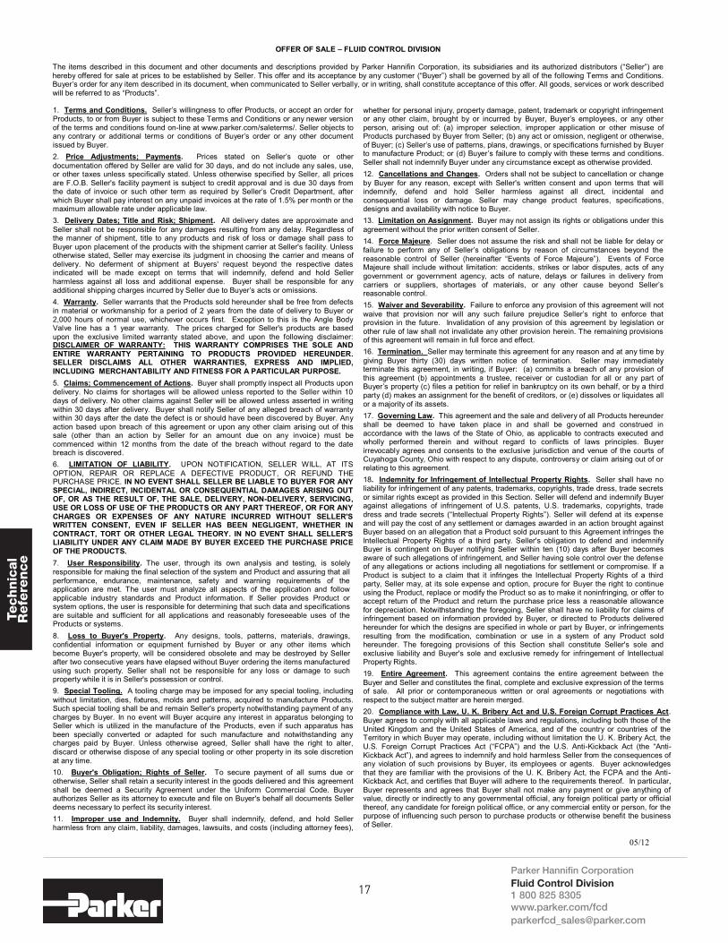
OFFER OF SALE – FLUID CONTROL DIVISION
The items described in this document and other documents and descriptions provided by Parker Hannifin Corporation, its subsidiaries and its authorized distributors (“Seller”) are hereby offered for sale at prices to be established by Seller. This offer and its acceptance by any customer (“Buyer”) shall be governed by all of the following Terms and Conditions. Buyer’s order for any item described in its document, when communicated to Seller verbally, or in writing, shall constitute acceptance of this offer. All goods, services or work described will be referred to as “Products”.
1. Terms and Conditions. Seller’s willingness to offer Products, or accept an order for Products, to or from Buyer is subject to these Terms and Conditions or any newer version of the terms and conditions found on-line at www.parker.com/saleterms/. Seller objects to any contrary or additional terms or conditions of Buyer’s order or any other document issued by Buyer. 2. Price Adjustments; Payments. Prices stated on Seller’s quote or other documentation offered by Seller are valid for 30 days, and do not include any sales, use, or other taxes unless specifically stated. Unless otherwise specified by Seller, all prices are F.O.B. Seller's facility payment is subject to credit approval and is due 30 days from the date of invoice or such other term as required by Seller’s Credit Department, after which Buyer shall pay interest on any unpaid invoices at the rate of 1.5% per month or the maximum allowable rate under applicable law. 3. Delivery Dates; Title and Risk; Shipment. All delivery dates are approximate and Seller shall not be responsible for any damages resulting from any delay. Regardless of the manner of shipment, title to any products and risk of loss or damage shall pass to Buyer upon placement of the products with the shipment carrier at Seller's facility. Unless otherwise stated, Seller may exercise its judgment in choosing the carrier and means of delivery. No deferment of shipment at Buyers' request beyond the respective dates indicated will be made except on terms that will indemnify, defend and hold Seller harmless against all loss and additional expense. Buyer shall be responsible for any additional shipping charges incurred by Seller due to Buyer’s acts or omissions. 4. Warranty. Seller warrants that the Products sold hereunder shall be free from defects in material or workmanship for a period of 2 years from the date of delivery to Buyer or 2,000 hours of normal use, whichever occurs first. Exception to this is the Angle Body Valve line has a 1 year warranty. The prices charged for Seller's products are based upon the exclusive limited warranty stated above, and upon the following disclaimer: DISCLAIMER OF WARRANTY: THIS WARRANTY COMPRISES THE SOLE AND ENTIRE WARRANTY PERTAINING TO PRODUCTS PROVIDED HEREUNDER. SELLER DISCLAIMS ALL OTHER WARRANTIES, EXPRESS AND IMPLIED, INCLUDING MERCHANTABILITY AND FITNESS FOR A PARTICULAR PURPOSE. 5. Claims; Commencement of Actions. Buyer shall promptly inspect all Products upon delivery. No claims for shortages will be allowed unless reported to the Seller within 10 days of delivery. No other claims against Seller will be allowed unless asserted in writing within 30 days after delivery. Buyer shall notify Seller of any alleged breach of warranty within 30 days after the date the defect is or should have been discovered by Buyer. Any action based upon breach of this agreement or upon any other claim arising out of this sale (other than an action by Seller for an amount due on any invoice) must be commenced within 12 months from the date of the breach without regard to the date breach is discovered. 6. LIMITATION OF LIABILITY. UPON NOTIFICATION, SELLER WILL, AT ITS OPTION, REPAIR OR REPLACE A DEFECTIVE PRODUCT, OR REFUND THE PURCHASE PRICE. IN NO EVENT SHALL SELLER BE LIABLE TO BUYER FOR ANY SPECIAL, INDIRECT, INCIDENTAL OR CONSEQUENTIAL DAMAGES ARISING OUT OF, OR AS THE RESULT OF, THE SALE, DELIVERY, NON-DELIVERY, SERVICING, USE OR LOSS OF USE OF THE PRODUCTS OR ANY PART THEREOF, OR FOR ANY CHARGES OR EXPENSES OF ANY NATURE INCURRED WITHOUT SELLER'S WRITTEN CONSENT, EVEN IF SELLER HAS BEEN NEGLIGENT, WHETHER IN CONTRACT, TORT OR OTHER LEGAL THEORY. IN NO EVENT SHALL SELLER'S LIABILITY UNDER ANY CLAIM MADE BY BUYER EXCEED THE PURCHASE PRICE OF THE PRODUCTS. 7. User Responsibility. The user, through its own analysis and testing, is solely responsible for making the final selection of the system and Product and assuring that all performance, endurance, maintenance, safety and warning requirements of the application are met. The user must analyze all aspects of the application and follow applicable industry standards and Product information. If Seller provides Product or system options, the user is responsible for determining that such data and specifications are suitable and sufficient for all applications and reasonably foreseeable uses of the Products or systems. 8. Loss to Buyer's Property. Any designs, tools, patterns, materials, drawings, confidential information or equipment furnished by Buyer or any other items which become Buyer's property, will be considered obsolete and may be destroyed by Seller after two consecutive years have elapsed without Buyer ordering the items manufactured using such property. Seller shall not be responsible for any loss or damage to such property while it is in Seller's possession or control. 9. Special Tooling. A tooling charge may be imposed for any special tooling, including without limitation, dies, fixtures, molds and patterns, acquired to manufacture Products. Such special tooling shall be and remain Seller's property notwithstanding payment of any charges by Buyer. In no event will Buyer acquire any interest in apparatus belonging to Seller which is utilized in the manufacture of the Products, even if such apparatus has been specially converted or adapted for such manufacture and notwithstanding any charges paid by Buyer. Unless otherwise agreed, Seller shall have the right to alter, discard or otherwise dispose of any special tooling or other property in its sole discretion at any time. 10. Buyer's Obligation; Rights of Seller. To secure payment of all sums due or otherwise, Seller shall retain a security interest in the goods delivered and this agreement shall be deemed a Security Agreement under the Uniform Commercial Code. Buyer authorizes Seller as its attorney to execute and file on Buyer's behalf all documents Seller deems necessary to perfect its security interest. 11. Improper use and Indemnity. Buyer shall indemnify, defend, and hold Seller harmless from any claim, liability, damages, lawsuits, and costs (including attorney fees),
whether for personal injury, property damage, patent, trademark or copyright infringement or any other claim, brought by or incurred by Buyer, Buyer’s employees, or any other person, arising out of: (a) improper selection, improper application or other misuse of Products purchased by Buyer from Seller; (b) any act or omission, negligent or otherwise, of Buyer; (c) Seller’s use of patterns, plans, drawings, or specifications furnished by Buyer to manufacture Product; or (d) Buyer’s failure to comply with these terms and conditions. Seller shall not indemnify Buyer under any circumstance except as otherwise provided. 12. Cancellations and Changes. Orders shall not be subject to cancellation or change by Buyer for any reason, except with Seller's written consent and upon terms that will indemnify, defend and hold Seller harmless against all direct, incidental and consequential loss or damage. Seller may change product features, specifications, designs and availability with notice to Buyer. 13. Limitation on Assignment. Buyer may not assign its rights or obligations under this agreement without the prior written consent of Seller. 14. Force Majeure. Seller does not assume the risk and shall not be liable for delay or failure to perform any of Seller’s obligations by reason of circumstances beyond the reasonable control of Seller (hereinafter “Events of Force Majeure”). Events of Force Majeure shall include without limitation: accidents, strikes or labor disputes, acts of any government or government agency, acts of nature, delays or failures in delivery from carriers or suppliers, shortages of materials, or any other cause beyond Seller’s reasonable control. 15. Waiver and Severability. Failure to enforce any provision of this agreement will not waive that provision nor will any such failure prejudice Seller’s right to enforce that provision in the future. Invalidation of any provision of this agreement by legislation or other rule of law shall not invalidate any other provision herein. The remaining provisions of this agreement will remain in full force and effect. 16. Termination. Seller may terminate this agreement for any reason and at any time by giving Buyer thirty (30) days written notice of termination. Seller may immediately terminate this agreement, in writing, if Buyer: (a) commits a breach of any provision of this agreement (b) appointments a trustee, receiver or custodian for all or any part of Buyer’s property (c) files a petition for relief in bankruptcy on its own behalf, or by a third party (d) makes an assignment for the benefit of creditors, or (e) dissolves or liquidates all or a majority of its assets. 17. Governing Law. This agreement and the sale and delivery of all Products hereunder shall be deemed to have taken place in and shall be governed and construed in accordance with the laws of the State of Ohio, as applicable to contracts executed and wholly performed therein and without regard to conflicts of laws principles. Buyer irrevocably agrees and consents to the exclusive jurisdiction and venue of the courts of Cuyahoga County, Ohio with respect to any dispute, controversy or claim arising out of or relating to this agreement. 18. Indemnity for Infringement of Intellectual Property Rights. Seller shall have no liability for infringement of any patents, trademarks, copyrights, trade dress, trade secrets or similar rights except as provided in this Section. Seller will defend and indemnify Buyer against allegations of infringement of U.S. patents, U.S. trademarks, copyrights, trade dress and trade secrets (“Intellectual Property Rights”). Seller will defend at its expense and will pay the cost of any settlement or damages awarded in an action brought against Buyer based on an allegation that a Product sold pursuant to this Agreement infringes the Intellectual Property Rights of a third party. Seller's obligation to defend and indemnify Buyer is contingent on Buyer notifying Seller within ten (10) days after Buyer becomes aware of such allegations of infringement, and Seller having sole control over the defense of any allegations or actions including all negotiations for settlement or compromise. If a Product is subject to a claim that it infringes the Intellectual Property Rights of a third party, Seller may, at its sole expense and option, procure for Buyer the right to continue using the Product, replace or modify the Product so as to make it noninfringing, or offer to accept return of the Product and return the purchase price less a reasonable allowance for depreciation. Notwithstanding the foregoing, Seller shall have no liability for claims of infringement based on information provided by Buyer, or directed to Products delivered hereunder for which the designs are specified in whole or part by Buyer, or infringements resulting from the modification, combination or use in a system of any Product sold hereunder. The foregoing provisions of this Section shall constitute Seller's sole and exclusive liability and Buyer's sole and exclusive remedy for infringement of Intellectual Property Rights. 19. Entire Agreement. This agreement contains the entire agreement between the Buyer and Seller and constitutes the final, complete and exclusive expression of the terms of sale. All prior or contemporaneous written or oral agreements or negotiations with respect to the subject matter are herein merged. 20. Compliance with Law, U. K. Bribery Act and U.S. Foreign Corrupt Practices Act. Buyer agrees to comply with all applicable laws and regulations, including both those of the United Kingdom and the United States of America, and of the country or countries of the Territory in which Buyer may operate, including without limitation the U. K. Bribery Act, the U.S. Foreign Corrupt Practices Act (“FCPA”) and the U.S. Anti-Kickback Act (the “Anti-Kickback Act”), and agrees to indemnify and hold harmless Seller from the consequences of any violation of such provisions by Buyer, its employees or agents. Buyer acknowledges that they are familiar with the provisions of the U. K. Bribery Act, the FCPA and the Anti-Kickback Act, and certifies that Buyer will adhere to the requirements thereof. In particular, Buyer represents and agrees that Buyer shall not make any payment or give anything of value, directly or indirectly to any governmental official, any foreign political party or official thereof, any candidate for foreign political office, or any commercial entity or person, for the purpose of influencing such person to purchase products or otherwise benefit the business of Seller.
17

Technic
al
Refe
rence
Parker Hannifin CorporationFluid Control Division1 800 825 8305 www.parker.com/[email protected]
FAVORITES
18

Technic
al
Refe
rence
PHONE NUMBERS
19

NOTES

Please refer to the coil chart number within the catalog to find the correct coil in the chart below.
COILS
Gold RingTM Voltage 1/2” NPT Conduit* DIN43650A/ISO4400
CHART 16 watts, Class F
24/60120/60-110/50240/60-220/50
AF4C01AF4C05AF4C15
-AFPH05AFPH15
Gold RingTM Voltage 1/2” NPT Conduit* DIN43650A/ISO4400
CHART 411 watts, Class F
24/60120/60-110/50240/60-220/50
CF4C01CF4C05CF4C15
-CFPH05CFPH15
CHART 516 watts, Class F
24/60120/60-110/50240/60-220/50
DF4C01DF4C05DF4C15
-DFPH05DFPH15
CHART 611.5 watts, Class F
12VDC24VDC
3F4C753F4C80
3FPH753FPH80
* 18” Lead Wires, Nema 1, 2, 3, 4, 4X** Hazardous location coil approval: Class I, Div I & II, Groups A, B, C, D; Class II, Div I & II, Groups E, F, G; Class III, Div I.*** 8.5 Watt For 2 - Way Normally Closed AC
Skinner® Voltage 1/2” NPT Conduit* DIN43650A/ISO4400 18” Leads
CHART 9AC 10 watts***
DC 8 wattsClass F
24/60120/60-110/50240/60-220/50
12VDC24VDC
C4EC4FC4GC4AC4B
-----
B4EB4FB4GB4AB4B
CHART 9AC 10 watts***
DC 8 wattsClass H
24/60120/60-110/50240/60-220/50
12VDC24VDC
-----
D6ED6FD6GD6AD6B
-----
Skinner® Voltage 1/2” NPT Conduit* DIN 43650A/ISO4400 Hazardous**
CHART 710 watts, Class F
24/60120/60-110/50240/60-220/50
12VDC24VDC
C111B2 C111P3C111Q3C111C1C111C2
D100B2D100P3D100Q3D100C1D100C2
-H111P3H111Q3H111C1H111C2
CHART 710 watts, Class H
120/60-110/50240/60-220/50
12VDC24VDC
C222P3 C222Q3C222C1C222C2
----
H222P3H222Q3
-H222C2
CHART 822 watts, Class H
120/60-110/5012VDC24 VDC
C322P3C322C1C322C2
---
H322P3H322C1H322C2

Together, we cancontrol virtually any media,in any application, under any condition.Parker Fluid Control’s 2-Way, 3-Wayand 4-Way valves are designed tooffer customers the ultimate inperformance, versatility and quality.
www.parker.com/fcd
Flip Out To Reveal Coil Chart

CAT FCDEXP0912 September 2012© 2012 Parker Hannifin CorporationParker Hannifin CorporationFluid Control Division
95 Edgewood Avenue New Britain, CT 060511-800-825-8305 [email protected]/fcd