Flue Gas Analyzer 716 / 716N - Test Products International
26
Test Products International, Inc. 9615 SW Allen Blvd., Ste. 104 Beaverton, OR 97005 Tel: 503-520-9197 Fax: 503-520-1225 www.tpi-thevalueleader.com Test Products International, Ltd. 342 Bronte Road South, Unit #9 Milton Ontario Canada L9T5B7 Tel: 905-693-8558 Fax: 905-693-0888 716 / 716N Flue Gas Analyzer The Value Leader TM www.tpi-thevalueleader.com
Transcript of Flue Gas Analyzer 716 / 716N - Test Products International

Test Products International, Inc.9615 SW Allen Blvd., Ste. 104
Beaverton, OR 97005Tel: 503-520-9197 Fax: 503-520-1225
www.tpi-thevalueleader.com
Test Products International, Ltd.342 Bronte Road South, Unit #9Milton Ontario Canada L9T5B7
Tel: 905-693-8558 Fax: 905-693-0888
716 / 716NFlue Gas Analyzer
The Value LeaderTM
www.tpi-thevalueleader.com

Contents
Introduction........................................................1General Overview.................................................1, 2Instrument Overview............................................. 3 ~ 7
Front View...............................................3Keypad...................................................4Back View...............................................5Side Views..............................................6Top View................................................ 7
Basic Analyzer Functions....................................... 8 ~ 10Charging The Analyzer................................ 8Turning The Analyzer On ............................ 9Turning The Analyzer Off............................. 10Display Backlight..................................... 10
Combustion Analysis Overview.................................11Measurements.................................................... 12 ~ 28
Flue Gas................................................ 12 ~ 21Typical Test Results...................................22Temperature & Pressure.............................23 ~ 24Tightness Test......................................... 25 ~ 26CO Room Test..........................................27Combustible Gas Leak Detection...................28
Menu Navigation................................................. 29 ~ 32Memory................................................ 29Fuel Type................................................30Analyzer Setup.........................................31Units of Measure, Sensor Info, Instrument Info. 32
Specifications..................................................... 33 ~ 34 Calibration & Service............................................ 35Warranty........................................................... 35Appendix A General Maintenance & Function Tests............36 ~ 38Appendix B A773 Sulfur Filter Installation & Maintenance....39 ~ 40Appendix C Error Codes and Troubleshooting....................41~ 42Appendix D Testing for Carbon Monoxide in Ambient Air......43Appendix E Carbon Monoxide Limits in Ambient Air Chart....44Appendix F Carbon Monoxide Facts...............................45Appendix G Battery Replacement..................................46
Notes:
Notes:Introduction
Thank you for purchasing TPI brand products. The TPI 716 Flue GasAnalyzer is a state of the art, easy to use analyzer designed not only todisplay and calculate the required readings from a flue but also tocover most of the other measurements associated with combustion.The instrument is ruggedly constructed and comes with a 3 Year unitand 2 Year sensor Guarantee.
General Overview
The TPI 716 combustion analyzer uses state of the art electrochemicalsensors. This sensor technology provides the longest lasting, mostaccurate and reliable means for performing combustion tests. The sen-sors in your analyzer will need to be replaced periodically and calibra-tion is recommended once every year.
Electrochemical sensors by nature are always active. Therefore thetime the analyzer is off and not being used must be taken into accountwhen determining sensor life. The sensors in your analyzer are war-ranted for two years. This warranty does not cover sensors damagedthrough misuse of the analyzer.
You should keep the battery of your 716 charged so power is constant-ly being supplied to your sensors.
The following guidelines will help prevent damage to your sensors:
Always use the mini pump filter when testing flue gases.Always periodically check and replace the mini pump filter as needed.Always make sure the in-line filter / water trap is installed properly.Always periodically check and replace the in-line filter as needed.Always remove water or condensation from the inside of the in-line fil-ter / water trap assembly prior to performing tests.Always use the optional oil filter (p/n A773) when performing tests onoil burning equipment unless you are using the 716N. Do not use theA773 with the 716N because the A773 will filter out NitricOxide (NO). 1

General Overview (Continued)
Never over saturate your sensors by performing tests on equipmentwith gas levels beyond the capability of you analyzer.
Always keep the A795 water trap / filter assembly clean and replace thefilter as necessary. Replacement filter part number is A794F.
This manual will guide you through the functions of the TPI 716 whichwill give you many years of reliable service.
Your TPI 716 Flue Gas Analyzer comes complete with the followingstandard accessories:
( ) Denotes part number
• TPI 716 Analyzer• Combustible Gase Leak Probe (A806)• Rubber Boot (A765) 1 each installed on analyzer• Soft Carrying Case (A768) - 1 each• Flue Sampling Probe (A770) - 1 each• In-Line Filter / Water Trap installed on Flue probe (A795) - 1 each• Disc water filter installed in water trap (A794W) - 1 each• Spare In-Line Filter - 1 each (A794F is a package of 5 filters)• Temperature Probe (GK11M) - 1 each• Battery Charger (A766) - 1 each• Mini Pump Protection Filter Assembly (A763) - 1 each• Exhaust Spigot Removable (A764) - 1 each• Pressure Tubing (A774) - 1 each 6’ piece• Static Pressure Tips (A776) - 2 each• 1/4” barbed to 1/8” NPT fitting (A603) - 2 each• Gas Valve Adapter (A611) - 1 each• Adapter Tubing (A791) - 1 each 4” piece• Instruction Manual
Your TPI 716 Flue Gas Analyzer has the following options available: • A807 PC Software and cable for communication to a PC. • A740 infrared printer (Included with 716A740)
2
Notes:

Appendix G: Battery ReplacementWhen the battery in your analyzer will no longer charge, no longer hold acharge, or if beeping is heard while charging this is usually an indication thebattery pack requires replacement.
For best results use a TPI replacement battery part number A007. The battery inyour analyzer is 3.6V NiMH 1600mAh rated. Never replace the battery with anyother type of battery or damage to the charge circuit will result.
The battery pack is replaced as follows:
1. Turn the analyzer over and locate the phillips head battery cover screw. Seepicture below.
2. Loosen the screw. Pull out on the screw to remove the battery cover.
3. Remove the old battery pack from the battery compartment. Pull the batterywire out of the connector.
4. Install the new battery pack by inserting the connector from the battery packinto the connector on the analyzer. Install the battery pack into the battery com-partment.
4. Re-install the battery cover by fitting the bottom part in first.
5. Tighten the battery cover screw.
Battery Cover
Battery Cover Screw
46
Instrument Overview
Front View
Rubber Boot Protects the instrument from accidental damage
Display Large graphical backlit LCD Display
Keypad Selects all available functions
RubberBoot
LCDDisplay
Keypad
NOTE: When selecting oil as fuel be sure to use the optionaloil filter (A773) or readings could become erratic. SeeAppendix E for installation instructions.
Do NOT use the A773 with the 716N analyzer. 3

Keypad
4
Blue Soft Keys - The function of these keys is shown in thelower part of the display and changes depending on whatmenu the analyzer is in.
In the picture center soft key controls the start function andthe left and right soft keys are disabled.
Up Arrow Key -This key is usedto scroll up inmenus.
Down ArrowKey - This keyis used to scrolldown in menus.
Home Key - This key isused to return to theMain Menu from anyother menu.
Back Key - This key isused to go back onemenu level.
On/Off Key - This key isused to turn the analyz-er on and off.
Appendix F: CARBON MONOXIDE FACTS
Carbon Monoxide (CO) is invisible, odorless, and tasteless. It is the byproduct ofcombustion and levels are elevated when there is incomplete combustion.
Sources of CO include: Unvented kerosene and gas space heatersLeaking chimneys & furnaces Gas water heaters Back drafting from furnaces Wood stoves& fireplaces Gas Stoves Automobile exhaust Tobacco smoke
Carbon Monoxide is picked up quickly in the body by red blood cells. At high lev-els of CO the body replaces oxygen with carbon monoxide.
The most common symptoms of CO poisoning are headache, dizziness, weak-ness, nausea, vomiting, chest pain, and confusion. High levels of CO inhalationcan cause loss of consciousness and death. Unless suspected, CO poisoning canbe difficult to diagnose because the symptoms mimic other illnesses.
People who are sleeping or intoxicated can die from CO poisoning before everexperiencing symptoms.
Please see the next page for a list of exposure times and symptoms.
45

Appendix E: Carbon Monoxide in Ambient Air Chart
This chart contains maximum exposure levels and times for carbon monoxide.This is a general guideline only. It is recommended you check with your localgovernment for guidelines in your area.
44
Back View
Calibration and Information Label: Displays calibration information andserial number
Battery Compartment: Holds rechargeable battery
Rubber Boot Protects the instrument
5
Calibration andInformationLabel
BatteryCompartment
RubberBoot

Side Views
Exhaust Port Port for connection of Exhaust Adapter
Infrared Window Window for sending stored data to IR Printer
Rubber Boot Protects the instrument from accidental damage
Measurements - Temperature & Pressure
ExhaustPort
InfraredWindow
RubberBoot
6
Appendix D: Testing for Carbon Monoxide in Ambient Air
The 716 can be used to test for carbon monoxide in ambient air. For exampletests can be performed in work spaces and living areas like offices and housesto ensure safety.
1. Following the steps outlined on page 8, turn the analyzer on in a clean airenvironment away from the area to be tested,
2. Select “Measurement” from the Main Menu. Select “Flue gas” from theMeasurements Menu. After a purge cycle the display below will be seen.
Ambient CO levels will be seen in the top lineof the display. (CO in ppm)
3. Connect the Pump Protection filter to the analyzer.
4. Begin testing for carbon monoxide. Move from space to space to detect anyCO that may be present. The CO reading will be seen in the top part of the dis-play.
5. If necessary, the flue probe can be attached to test in ducts and plenums.
6. Refer to the chart on page 50 for a list of exposure times and levels of carbonmonoxide in ambient test applications and page 51 for carbon monoxide facts.
7. When testing is complete, turn the analyzer off as outlined on page 8.
43

Problem Possible Cause Corrective Action
Efficiency reading incorrect NET efficiency selected.
Ambient temperature probe notplugged in to T2.
Incorrect fuel selected.
Select GROSS efficiency. See page13.
Plug ambient probe into T2. Seepage 14.
Select the proper fuel for the equip-ment being tested. See page 13.
Readings are erratic when workingon oil fired equipment.
Oil filter not installed or installedincorrectly (716 only).
Make sure the optional sulfur filter(A773) is installed. See Appendix B.
One or all of the following parame-ters; Ratio, CO air free, excess air,and efficiency read and print dashes.
Measured values are such that thecalculated values of these parame-ters are out of range.
Redo combustion test. Since theseare calculated values, the measurevalues must be within certain levelsfor these to display. If the measuredoxygen level is above 19.9% theseparameters won’t read.
These parameters might not displayor be applicable in some tests.
Pressure prints as “N/A” on my com-bustion analysis print out.
During combustion analysis if a pres-sure measurement is not being madethis parameter will print as not beingused.
Perform the combustion test andalso connect the manometer andmonitor pressure.
Battery will not charge or hold acharge.
Defective charger or battery. Replace the charger or battery.
Send to TPI for service.
Beeping noise heard during charg-ing.
Defect in charging circuit or shortedbattery.
Disconnect from the charger andcontact TPI at 800-368-5719.
Analyzer won’t turn off Oxygen and/or carbon monoxide lev-els outside limits.
Allow the analyzer to purge longer.
Appendix C: ERROR CODES & TROUBLESHOOTING (Continued)
Pressure sensor will not zero. Pressure sensor needs to be reset. Send to TPI for calibration.
42
Charger Socket Connection for 220V/115V charger
T1 Socket Connection for thermocouple plug on flue probe
Connection for any 'K' type thermocouple probe
T2 Socket Connection for ambient 'K' type thermocouple probe
Connection for any 'K' type thermocouple probe
Gas Sample Port Connection for Mini Pump Protection Filter and Flue Probe
P (+) Port Connections for Pressure Tubing P (-) Port
USB Port Connection for optional A807 cable for communicationto a PC or connection for A806 combustible gas leakdetection probe.
Top View
7
ChargerSocket
USB Port
P(+)Port
P(-)Port
GasSamplePort
T1 SocketT2 Socket
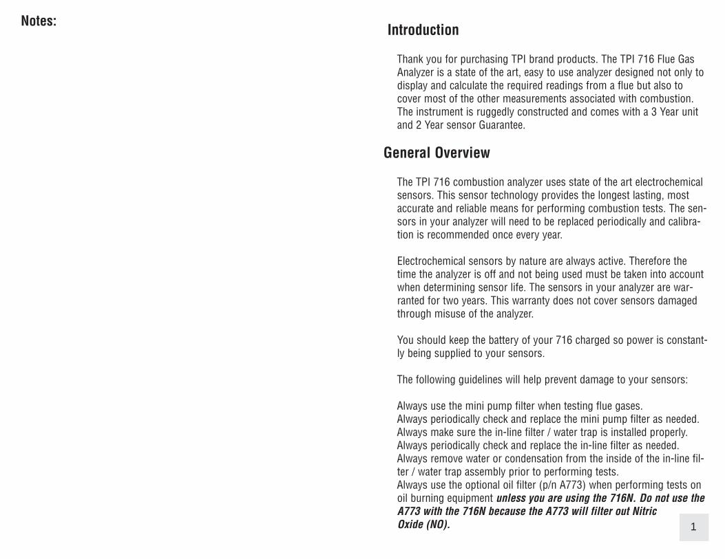
BASIC ANALYZER FUNCTIONSCharging The AnalyzerPlug the charger into the charger socket on the instrument (see page 7).When the charger is plugged in the battery level display will turn on. This dis-play indicates the analyzer is being charged and the status of the charge.
8
The plug symbol confirms the analyz-er is connected to the charger. Thebattery symbol shows the chargelevel when the analyzer is on too.
The charge level is represented ingraph form as well. The charge is dis-played in percentage. (0 to 100%)
During operation the analyzer will display charge status and battery condition inthe top right corner of the display.
Battery is at full capacity.
Battery is at 2/3 capacity.
Battery is at 1/3 capacity. The charger should be connected soon.
Battery is very low and needs to be recharged immediately
Indicates the analyzer is connected to the charger.
If a beeping noise is heard during charging disconnect the charger. This is anindication the battery pack needs to be replaced. Please see Appendix G for bat-tery replacement instructions.
Appendix C: ERROR CODES & TROUBLESHOOTINGCode
DisplayedCode Definition Possible Causes Corrective Action
FlowError
Pump not drawing sample atcorrect flow rate.
Blockage / kink in flue probehose.
Dirty or blocked filter(s).
Worn pump.
Check and rectify. SeeAppendix A.
Replace filter(s). SeeAppendix A.
Return to TPI for service.
InItO2Err
Oxygen sensor failed to ini-tialize
Flue probe connected to 716prior to power up.
716 did not purge completelyfrom last sample.
Worn or defective oxygensensor.
Disconnect probe andrestart.
Purge for 20 minutes andrestart.
Return to TPI for sensorreplacement.
InItCOErr
Carbon monoxide sensorfailed to initialize.
Flue probe connected to 716prior to power up.
716 did not purge completelyfrom last sample.
Worn or defective carbonmonoxide sensor.
Disconnect probe andrestart.
Purge for 20 minutes andrestart.
Return to TPI for sensorreplacement.
Lobat
Low battery. Battery needs to be charged. Charge battery. If the batterywon’t hold a charge, replacethe battery.
oFL Overflow indication. Thepressure being measured isoutside the maximum mea-surement capability.
Pressure being measured istoo high or low.
Pressure sensor damaged ordefective.
Remove pressure source.
Return to TPI for service.
oFL Overflow indication. The tem-perature being measured isoutside the maximum mea-surement capability.
Temperature being measuredis too high or low.
Remove pressure source.
oPEn Unable to read thermocouple(temperature).
Temperature probe not con-nected to input.Worn temperature sensor.
Connect temperature probeto analyzer.Replace temperature probeor flue probe.
41
Appendix B: A773 SULFUR FILTER INSTALLATION & MAINTENANCE
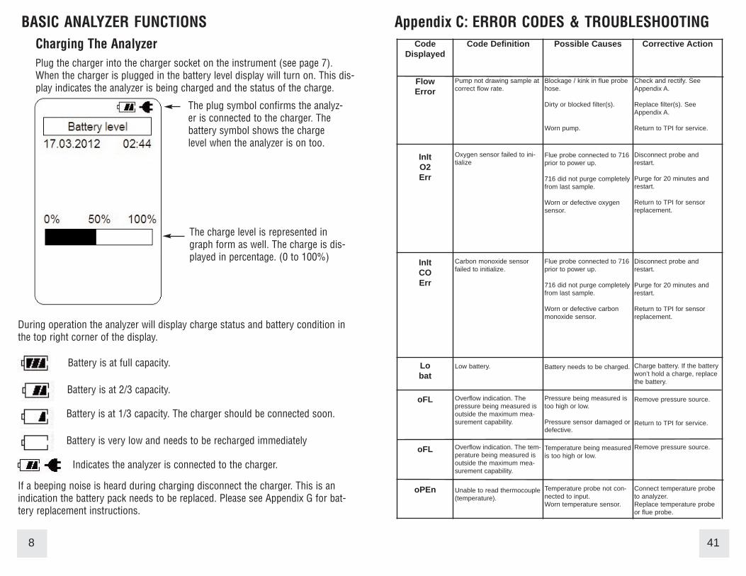
4. Beginning on the “Flue Probe” side of the A773 sulfur filter, pull the yellowthermocouple cord out of the channel of the flue probe tube. Pull out approx-imately the length of the water trap that was removed.
5. Being careful not to cut the yellow cord, cut out a section of the flue probetubing the length of the water trap on the “Flue Probe” side of the A773 sul-fur filter. (See picture below)
6. Install the water trap in the flue probe hose where the piece was cut out. Makesure the water trap is positioned correctly. The water trap lid should face the“Hose End” side of the hose. (See picture below)
A773 SULFUR FILTER MAINTENANCE:
The A773 should be replaced when most of the pellets become discolored, usual-ly white or black.
If the A773 begins to trap condensate and fill with water but the pellets are notdiscolored to the point replacement is required, it should be removed and allowedto dry. Once it is dry it can be reused.
40
Turning The Analyzer OnAlways: - Before turning on please ensure nothing is connected to the GasSample Port (see page 7)
Press and hold the ON/OFF key down for approximately 3 seconds. The 716will beep and the initial start up screen will be displayed.
After the initial start up screen displays for approximately 5 seconds the Mainmenu will be displayed.
The initial start up screen displays thefollowing information:
Model number of the analyzer
Firmware versionFirmware dateSerial number of the analyzer
Last calibration date of the sensors
Note: The NO sensor calibration datewill only display for 716N models.
The main menu displays the followinginformation:
Battery status
Date (dd.mm.yyyy format) and time(24hr clock)
Menu Selections
Left blue soft key activates Bluetooth(Only models equipped with this option.)
Center blue soft key confirms selection
9

Turning The Analyzer Off
Always: - Before turning off return the instrument to a clean air environmentand allow the Carbon Monoxide level to return below 15ppm and the Oxygenlevel to return to 20.9% (± 0.3%) Press the Power Key to turn the instrumentoff:- NOTE The Instrument will not allow itself to be switched off if the CO isabove 15ppm
When the 716 is turning off the following screen is seen:
Display Backlight
The display backlight is factory set to Auto. A sensor located on the side ofthe analyzer detects the amount of ambient light and automatically adjuststhe backlight intensity.
The backlight can be manually adjusted to a desired level by the user. Pleaserefer to Menu Navigation - Analyzer Setup on page 31.
10
The instrument has an auto shut off facto-ry set for 10 minutes should no keys havebeen pressed for this period and the COlevel is below 15ppm. The auto power offcan be set to a different time or disabled.Please refer to Menu Navigation - AnalyzerSetup on page 31.
If the CO level is close enough to 0ppmand the O2 level is close enough to 20.9%the analyzer will display “Skip”. Thisallows you to skip the purge by pressingthe middle soft key.
Appendix B: A773 SULFUR FILTER INSTALLATION & MAINTENANCE
USE THE A773 ONLY WITH THE 716. DO NOT USE WITH THE 716N.
When using a 716 and performing combustion tests on oil fired equipment itis important to use the optional A773 sulfur filter. Failure to do so can resultin incorrect and readings. This filter also protects the sensors from theaffects of sulfur. The A773 does not have to be removed when working withother types of fuels.
PROCEDURE
1. Begin with the water trap section of the flue probe oriented as shown in thepicture below.
2. Remove the water trap from the flue probe hose. (See picture below)
3. Insert the A773 sulfur filter flue probe tube where the water trap wasremoved. (See picture below)
39

Appendix A: General Maintenance (continued)
Flue Probe Integrity Check
NOTE: Perform this check after performing the Pump Operation Check outlinedon the previous page.
1. Turn the analyzer on as outlined on page 8. Do not connect anything to theinlet. Wait until the analyzer has completed the initial purge and sensor checkand is operating normally prior to proceeding to step 2.
2. Connect the A763 mini pump protection filter and flue probe assembly to theinlet of the analyzer and the yellow thermocouple connector to input T1.
3. Repeatedly press the Scroll/Enter key until temperature is displayed. If thedisplayed temperature is approximately the ambient temperature the thermo-couple is operating properly and you may proceed to the next step to continuethe test. If the displayed temperature is “OL” the thermocouple is open and theprobe is in need of factory service.
4. Cover the end of the flue probe with a small piece of tube and pinch the endclose. After a short period of time the analyzer should display “Flow Error” anda rapid beeping should be heard. If this happens the flue probe his operatingproperly and the integrity test is complete. If the analyzer does not display “FlowError” this is an indication of a possible leak somewhere in the flue probe andyou may proceed to the next step for further tests.
5. Pinch the hose below the handle of the flue probe. If the analyzer displays“Flow Error” there is a leak in the handle assembly and the probe needs to befactory serviced. If the analyzer does not display “Flow Error” proceed to thenext step for further tests.
6. Pinch the hose between the analyzer and the water trap. If “Flow Error” stilldoes not display there may be an internal leak, pump problem, or other issueand the analyzer needs to be factory serviced. If “Flow Error” is displayed thereis a leak in the water trap assembly and the water trap assembly should bechecked as outlined on page 36 & 37.
38
COMBUSTION ANALYSIS OVERVIEWPerforming combustion analysis is very important to the overall safety andefficiency of heating equipment. The following guidelines and descriptions aregeneric and meant to provide you with a basic understanding of combustiontesting. TPI always recommends you contact the manufacturer of the deviceunder test, obtain information specific to the device, and follow the proce-dures and safety guidelines for performing tests and affecting repairs.
In general, for most applications, flue gas samples should be taken prior tothe draft diverter or any other opening that allows room air to enter the sys-tem. This prevents room air from mixing with gases in the flue and dilutingthe test sample. To ensure accurate and consistent combustion tests, it isimportant gas and temperature samples be taken at the same location. This iseasy with the TPI flue probe because the temperature sensor is an integralpart of the probe.
Prior to taking a sample, the device under test should be on and operating.Putting the flue probe in the sample area prior to starting the device maycause saturation of the sensors due to the higher initial concentration of car-bon monoxide that may be encountered upon start up. If this happens, allowyour analyzer to purge in fresh air until the carbon monoxide level returns to0 ppm and the oxygen level returns to 20.9%. This may take more than anhour depending on how saturated the sensors are.
The figures on pages 16 through 18 show locations for performing tests oncommonly encountered equipment. Remember to consult with the manufac-turer of the device under test for specific test information.Pressing the Func Key enables access to the different functions available onthe 716. The default function is Combustion Analyzer. Other available func-tions are: Thermometer, Manometer/Tightness Test, Combustible Gas LeakDetector, and Date / Time display.
11

MEASUREMENTS - Flue GasNote: It is recommended you perform routine general maintenance on youranalyzer to ensure proper function. Please refer to Appendix A for generalmaintenance schedule and function tests.
12
The pump will start and the Zeroing screen will display. The analyzer is initializing and self testing the sensors during this 30 second cycle.
The selected fuel type will be displayed and can be changed as necessary (see pg 13).
The selected unit of efficiency is displayed and can be changed as necessary (see pg 13).
If the analyzer is ready for use, “Skip” will appear above the center soft key. Pressing this will bypass the 30 second countdown.
Turn the 716 on as outlined on page 8. After the initial start up screen the Main Menu will be displayed.
Using the Arrow keys select Measurements by highlighting it.
Press the Enter key (center soft key) to con-firm the selection.
The Measurements menu will be displayed.
Using the Arrow keys select Flue gas by highlighting it.
Make sure the analyzer is in a clean air environ-ment with only the pump protection filter con-nected to the input.
Press the Enter key (center soft key) to confirm the selection.
Appendix A: General Maintenance (continued)Filter Check Continued
The other two filters are located in the water trap. The main filter is the A794Fparticle filter. This filter stops debris and dust from traveling down to the analyz-er. The secondary filter is the A794W water block filter. This filter stops flow inthe event the water trap fills with condensate. Refer to the picture below.
Open the water trap and look at the A794F particle filter. The filter will typicallyget dirty from the inside first. If the filter is dark on the inside a replacement fil-ter should be installed.
If the A794F is clean but saturated with water a replacement should be installedto ensure proper flow. The saturated filter can be left to dry and reused later.
Pump Operation Check
1. Turn the analyzer on as outlined on page 8. Do not connect anything to theinlet. Wait until the analyzer has completed the initial purge and sensor checkand is operating normally prior to proceeding to step 2.
2. Cover the analyzer inlet with your finger. The analyzer should display “FLOERR” and a rapid beeping should be heard.
If the analyzer does not beep and display “FLO ERR” this may be an indicationthe flow sensor requires calibration, the pump is faulty, or there is an internalleak. The analyzer should be returned for factory service.
Water trap bowl. A794water trap pictured. A795water trap is similar butlonger
A794FParticle Filter
A794WWaterBlock Filter
Water trap lid. O-ring islocated in the lid recess
A794D FilterSpacer Disc
37

Appendix A: General MaintenanceAll combustion analyzers use consumable items such filters and probes. Theseitems are user serviceable and can be taken care of by the operator.
The consumable items that will require operator attention are the water trap / fil-ter assembly, flue probe, pump protection filter, and ambient temperature probe.
The recommended maintenance schedule for your analyzer is as follows:
Maintenance Performed FrequencyWater trap Check Once per week (Once per day for analyzersFilter Check that see heavy use or are used in oil fired
applications) Pump Operation Check Once per month (More often for analyzersFlue Probe Integrity Check that see heavy use or are used in oil firedThermocouple Probe Check applications)
Water Trap CheckVisually check the water trap for:
1. Cracks in the bowl.2. Broken ears on the bowl where the lid locks on.3. Broken ears on the lid.4. Worn out o-ring on the lid.5. Loose connection to the flue probe tubing.
Filter Check
Signs of dirty or water saturated filters are a slow pump, flow error displayedwhen the flue probe is connected, and measurements that take longer than nor-mal.
TPI analyzers use three filters to protect the pump and sensors. The first filter tocheck is the A763 mini pump protection filter. (see picture below)
Inspection Window
Pump Protection Filter
Look in the inspection window to check the filter. When the filter materialbecomes dark, pull the black nose cone out of the tubing and replace the ball fil-ter inside.
36
MEASUREMENTS - Flue Gas (continued)
As necessary, the fuel type can be changed tomatch the fuel type of the equipment under test.The fuel type is used in the efficiency calculationand therefore it is important the fuel type is cor-rect in order for the calculation to be accurate.
To change the fuel type use the Arrow keys tohighlight “Fuel change”.
Press the Chang key (left soft key) and the fuelmenu will display.
The Arrow keys are used to scroll through theavailable fuel types.
The available fuels are Natural gas, Light oil,Heavy oil, LPG, Bituminous coal, Anthracite coal,Coke, Butane, Wood (dry), and Bagasse.
Once the desired fuel type is highlighted pressthe center soft key (OK) to confirm the selection.
The analyzer will return to the Zeroing displayand the countdown will continue.
The unit of efficiency can be changed as neededbetween Nett and Gross. Nett eficiency doesn’ttake into account wet losses while Gross efficien-cy does. In the USA Gross efficiency is used. IfNett is selected the efficiency will be displayed asmuch higher than it is.
Press the right soft key (Next) to highlight“Efficiency” in the display.
Press the Chang key (left soft key) and the effi-ciency menu will display.
Use the Arrow keys to select the desired efficien-cy unit and press the center soft key (OK) to con-firm the selection.
13

After the initial purge cycle is complete or skip ispressed the Flue gas measurement screen willdisplay.
This screen displays all combustion parametersincluding temperature and pressure.
MEASUREMENTS - Flue Gas (continued)
Connect the Pump Protection Filter assembly and Flue Probe Tubing completewith In-Line Filter to the Gas Sample Port and the 'K' Type Thermocouple Plugfrom the Flue Probe into Thermocouple (T1) Socket. The GK11M ambient airtemperature probe is connected to the (T2) socket. (See below & page 7)WARNING: - Ensure the 'K' type thermocouple probes are inserted into the sock-ets correctly (see page 7). The plugs are polarity marked and forcing the plug intothe socket the wrong way may result in damage to the instrument.
In-line FilterAssembly
Ambient AirConnection (T2)
Flue ProbeTubing
GK11M ProbeThermocoupleConnection fromFlue Probe
Pump Protection Filter
Press the center Blue Soft Key (Start) and the pump will start.
14
CALIBRATION & SERVICE
It is recommended that your analyzer be calibrated every 12 months. Please consult Test Products International for further details or send your analyzer to the address below for service.
TPI / Attn. Repair9615 SW Allen Blvd. Suite 104Beaverton, OR 97005
Please include your name, contact information, return address, and a briefdescription of the service required.
The following are consumable parts for the instrument:
In-Line Filter Element (pkg of 5) User Replaceable A794FDisc water filter User Replaceable A794WMini Pump Protection Filter Assem. User Replaceable A763 **Oxygen Sensor User / Factory Replaceable A761**Carbon Monoxide Sensor User / Factory Replaceable A760**Nitric Oxide Sensor User / Factory Replaceable A793**Sensor replacement requires calibration gas.
These items require periodic replacement as the analyzer is used.Please see Appendix A on page 37 for general maintenance informa-tion.
WARRANTY
Your TPI 716 Flue Gas Analyzer is guaranteed free from defects in materialsand workmanship for 3 Years from the date of purchase. The sensors carry a2 Year warranty. This guarantee does not affect your statuary rights. For addi-tional information please refer to the included warranty card or contact TPI at800-368-5719.
To obtain warranty performance or maintenance on your analyzer: - Includewith the product your name, address, phone number, written description ofthe problem and proof of purchase date. Carefully package and return to:
TPI / Attn. Repair9615 SW Allen Blvd. Suite 104Beaverton, OR 97005
35

SPECIFICATIONS (Continued)
Gases Range Resolution AccuracyOxygen 0-25% 0.1% +/- 0.3%
Carbon Monoxide 0-10,000 ppm 1 ppm +/- 5 ppm or 5%Whichever is greater
Nitric Oxide * 0-5000ppm 1ppm +/- 5ppm (<100ppm)+/- 5% (<1000ppm)+/- 10% (>1000ppm)
Carbon Dioxide 0-25% 0.1% Calculated
CO/CO2 Ratio 0-0.999 0.001 Calculated
Combustion Efficiency 0-100% 0.1% Calculated
Gas Leak Sensor 100-10,000 ppm (calibrated to methane)
*716N Model Only
Pressure MeasurementSelectable Ranges mbar, psi, inH2O, mH2O, kPa, hPa,
inHg, mmHg
Range - 150 mbar to + 150 mbar-15 kPa to + 15 kPa-60 inH2O to 60 inH2O
Resolution 0.01 mbar, 0.001 kPa, 0.001 inH2O
Accuracy +/- 0.5% fsd
Temperature MeasurementInput Type K-Type thermocouple
Range -58°F to 1832°F (-50°C to 1000°C)*
Resolution 1°F (1°C)
Accuracy +/- (0.3% of rdg + 2°F) or +/- (0.3% of rdg + 1°C)
* The thermocouple supplied (GK11M) has the ability to measure tempera-tures in the -50°F to 950°F range.
34
IMPORTANT: Prior to taking a sample, the device under test should be on andat operating temperature. Putting the flue probe in the sample area prior tostarting the device may cause saturation of the sensors due to the higherinitial concentration of carbon monoxide that may be encountered uponstart up. If this happens, allow your analyzer to purge in fresh air until thecarbon monoxide level returns to 0 ppm and the oxygen level returns to20.9%. This may take more than an hour depending on how saturated thesensors are.
Drill a 1/4 inch hole into the flue of the device under test. For most applica-tions, flue gas samples should be taken prior to the draft diverter or anyother opening that allows room air to enter the system. This prevents roomair from mixing with gases in the flue and diluting the test sample.
It is important to use manufacturers recommended test locations wheneverpossible.
Refer to the figure below for calculating the sample hole location. The figures on the following pages show typical test locations on commonlyencountered equipment.
15
MEASUREMENTS - Flue Gas (continued)

MEASUREMENTS - Flue Gas (continued)
TYPICAL TEST LOCATIONS
Atmospheric Gas Fired Fan Assist Boiler / Furnace
Typical Test Locations
Figure 1
It is important to use manufacturers recommended test locationswhenever possible.
16
SPECIFICATIONS
InstrumentOperating Temperature Range 14°F to +122°F (-10°C to +50°C)
Battery / Battery Life Rechargeable Ni-MH / > 6 Hours
Charger Input Voltage 115V or 230V : 50/60 Hz AC
Fuels Natural Gas, LPG, Light Oil, Heavy Oil,Bituminous Coal, Anthracite Coal, Coke, Butane, Wood, Bagasse
Pressure Ranges mbar, psi, inH2O, mH2O, kPa, hPa, inHg, mmHg
Display Backlit Graphic LCD
Data Storage 100 sets of readings, multiple pages
Single Logging 150 sets of time stamped readings
Time & Date 24 Hour Real Time Clock
Dimensions 7.8” (200mm) x 3.5” 90mm x 2.4” (60mm)
Weight 1.1lbs (500g)
Conforms to BS7927 (and the draft BS7967)
Flue Temperature ProbeConstruction Pistol Grip with Stainless Steel Shaft
Hose Length 8.2’ (2500mm)
Insertion Length 7.9” (200mm)
'K' Type Thermocouple Accuracy +/- 0.3% of fullscale, +/- 2°F (1°C)
Maximum Temperature 1472°F (800°C)
33

Menu Navigation - Units of Measure
1. From the main menu use the Arrow keys to select “Units of Measure” andpress the “Enter” key (center blue soft key).
2. The Units of Measure menu will display. The following parameters are accessi-ble in this menu. Use the Arrow keys and center blue soft key to select the appro-priate parameter.
Temperature - Select between °C and °F for temperature measurements.
Pressure - Select between mbar, psi, inH2O, mmH2O, kPa, hPa, inHg, and mmHgunits of measure for pressure readings..
Efficiency - Select between Nett and Gross efficiency. Gross efficienc is used inthe USA and factors in wet losses. Using Nett efficiency in the USA will result inabnormally high efficiencies.
Menu Navigation - Sensor Info
Allows the user to see the last and next calibration date of the sensors that areinstalled in the 716.
Menu Navigation - Instrument Info
Provides the serial number, firmware version, and firmware date for reference.Also shows the last calibration date of the unit and batter voltage / condition.
Menu Navigation - Calibration Mode
This is for factory use only.
32
Condensing Boiler / Furnace
Typical Test Locations
Figure 2
It is important to use manufacturers recommended test locationswhenever possible.
17
MEASUREMENTS - Flue Gas (continued)
TYPICAL TEST LOCATIONS

Test all exhaust ports at thetop of the heat exchanger.
Atmospheric Forced Air Furnace
Typical Test Locations
Figure 3
It is important to use manufacturers recommended test locationswhenever possible.
18
MEASUREMENTS - Flue Gas (continued)
TYPICAL TEST LOCATIONS
Menu Navigation - Analyzer Setup
1. From the main menu use the Arrow keys to select “Analyzer Setup” and pressthe “Enter” key (center blue soft key).
2. The Analyzer Setup menu will display. The following parameters are accessiblein this menu. Use the Arrow keys and center blue soft key to select the appropri-ate parameter.
Display type - Allows the display to be switched between 8 line and 4 line.
Date / Time - Used to set the current date and time. The date is in dd:mm:yyyyformat and the time is a 24 hour clock.
Contrast - Lighten or darken the display contrast.
Backlight - Adjust the backlight level from off to full brightness or set it to autoand the 716’s internal sensor will control the backlight brightness depending onambient light.
Alarm limits - Set the level at which the CO alarm sounds. The level is adjustablefrom 10ppm to 3000ppm and can be turned off. Default level is 2000ppm.
Print Header - Enables the two line header on printouts to the infrared printer tobe set with your companies information. After pressing “Enter” you will be askedfor a password. Enter “7160” and press “OK”. Select Header Line 1 and then usethe Arrow keys to enter line one of the header. Press “Enter” then repeat theprocess for line 2 of the header.
Auto Power - Enables the auto power off time to be set. The timer can be disabledor set to one of the following times; 5, 10, 20, 30, or 60 minutes. If a key has notbeen pressed during the time set, the analyzer will automatically begin to turn off.
Memory - Enables memory maintenance as outlined on page 29.
31

Menu Navigation - Fuel Type
1. From the main menu use the Arrow keys toselect “Fuel Type” and press the “Enter” key (cen-ter blue soft key).
30
2. Use the Arrow keys to select the fuel type. Scrolling down displays the rest ofthe available fuel types.
3. press the “OK” key (center blue soft key) to confirm the selection.
Fuel type can also be changed from the flue gas zeroing screen as outlined earlierin this instruction manual.
MEASUREMENTS - Flue Gas (continued)
Insert the flue probe into the sample hole of the device under test. The probe tipshould be in the middle of the flue pipe or exhaust stream.
Ensure the In-Line Filter / Water Trap hangs below the analyzer in the proper ver-tical position when readings are being taken. Failure to comply reduces the effec-tiveness of the water trap and may result in damage to the instrument. Refer tothe pictures below for correct and incorrect use.
WARNING: - Should the CO reading rise above 2,000ppm a continuous series ofAlarm Beeps will be heard. The Probe should immediately be disconnected fromthe instrument and the instrument returned to a clean air environment. This Alarmalerts the user that there is a high concentration of CO, and this procedure willprotect the sensors within the instrument. The alarm level can be changed. Pleasesee Appendix D
Make sure to check the water trap periodically during testing to ensure it does notfill with condensate and empty it as necessary. If the filter begins to fill during atest, open the lid and empty out the condensate. After closing the lid, allow read-ings to stabilize again.
IMPORTANT: The water trap is fitted with a water block filter (p/n A794W) in thelid to prevent water from flowing down into the pump. If the water trap fills thewater block filter will stop the flow to the analyzer and FLO ERR will display. Thewater trap should be emptied immediately if this happens. The water block filtermay need to be dried out or replaced before testing can resume.
19
MEASUREMENTS - Flue Gas (continued)
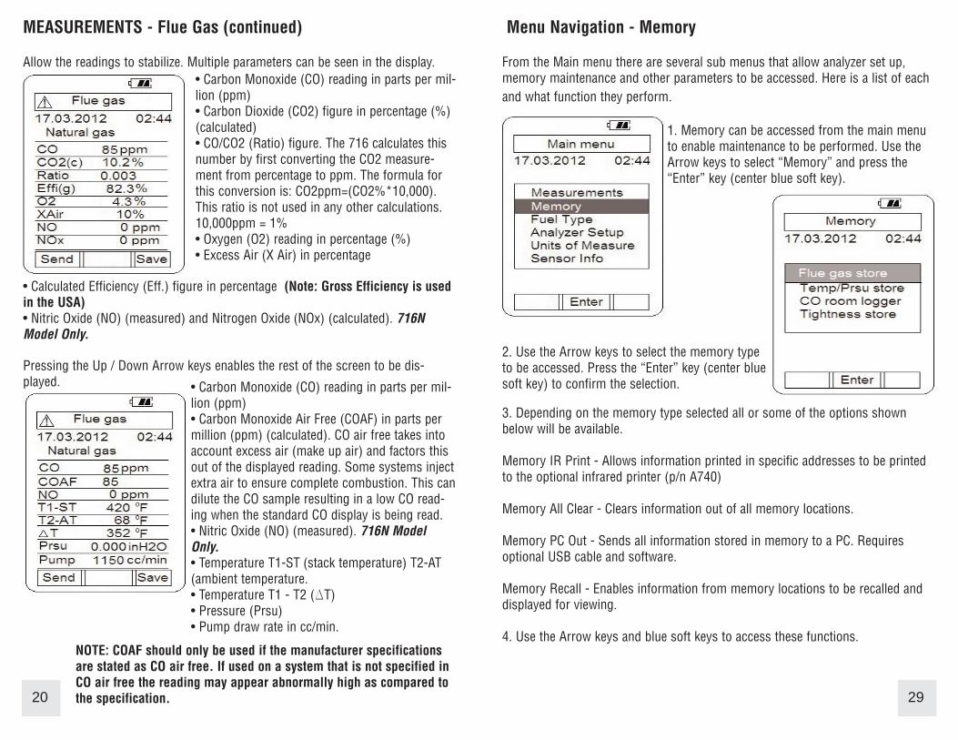
Allow the readings to stabilize. Multiple parameters can be seen in the display.
Pressing the Up / Down Arrow keys enables the rest of the screen to be dis-played.
20
• Carbon Monoxide (CO) reading in parts per mil-lion (ppm)• Carbon Dioxide (CO2) figure in percentage (%)(calculated)• CO/CO2 (Ratio) figure. The 716 calculates thisnumber by first converting the CO2 measure-ment from percentage to ppm. The formula forthis conversion is: CO2ppm=(CO2%*10,000).This ratio is not used in any other calculations.10,000ppm = 1%• Oxygen (O2) reading in percentage (%)• Excess Air (X Air) in percentage
• Carbon Monoxide (CO) reading in parts per mil-lion (ppm)• Carbon Monoxide Air Free (COAF) in parts permillion (ppm) (calculated). CO air free takes intoaccount excess air (make up air) and factors thisout of the displayed reading. Some systems injectextra air to ensure complete combustion. This candilute the CO sample resulting in a low CO read-ing when the standard CO display is being read. • Nitric Oxide (NO) (measured). 716N ModelOnly.• Temperature T1-ST (stack temperature) T2-AT(ambient temperature.• Temperature T1 - T2 (DT)• Pressure (Prsu)• Pump draw rate in cc/min.
• Calculated Efficiency (Eff.) figure in percentage (Note: Gross Efficiency is usedin the USA)• Nitric Oxide (NO) (measured) and Nitrogen Oxide (NOx) (calculated). 716NModel Only.
NOTE: COAF should only be used if the manufacturer specificationsare stated as CO air free. If used on a system that is not specified inCO air free the reading may appear abnormally high as compared tothe specification.
Menu Navigation - Memory
From the Main menu there are several sub menus that allow analyzer set up,memory maintenance and other parameters to be accessed. Here is a list of eachand what function they perform.
1. Memory can be accessed from the main menuto enable maintenance to be performed. Use theArrow keys to select “Memory” and press the“Enter” key (center blue soft key).
29
2. Use the Arrow keys to select the memory typeto be accessed. Press the “Enter” key (center bluesoft key) to confirm the selection.
3. Depending on the memory type selected all or some of the options shownbelow will be available.
Memory IR Print - Allows information printed in specific addresses to be printedto the optional infrared printer (p/n A740)
Memory All Clear - Clears information out of all memory locations.
Memory PC Out - Sends all information stored in memory to a PC. Requiresoptional USB cable and software.
Memory Recall - Enables information from memory locations to be recalled anddisplayed for viewing.
4. Use the Arrow keys and blue soft keys to access these functions.

Measurements - Leak DetectionThe Leak Detection function enables the 716 to test for combustible gas leaks ingas valves and fittings using the included gooseneck probe.
1. Connect the combustible gas probe to the USB connector located on the top ofthe 716. See picture below.
2. From the main menu select “Measurement” asoutlined on page 12. From the “Measurements”menu select “Leak detection” and the followingscreen will display.
3. The 716 will begin to countdown from 30.During this time the combustible sensor is beingwarmed up and prepared for use. A light in thesensor cage will illuminate and can be used to aidin seeing fittings in dark areas.
4. After the warm-up period is complete the Leakdetection screen will display and a constant tickwill be heard. Use the combustible gas probe tobegin looking for leaks.
5. When a leak is encountered the tick rate willincrease and the Low to High bar graph will visu-ally indicate a leak. Press the “Zero” key (left bluesoft key) to reset (nullify) the tick and continuelooking for the leak. Repeat this process until theprobe is directly over the source of the leak.
6. Press the “Exit” key (center blue soft key) toreturn the 716 to the “Measurements” menu.
28
Connect the com-bustible leakprobe here.
Combustible Gas Probe (A806)
MEASUREMENTS - Flue Gas (continued)
21
Test data can be saved to a memory location ifrequired.
1. Press the Save key (right blue soft key) and“Real Data Save” and “Address:” will be dis-played.
2. Using the Up and Down Arrow keys select thememory location to save the data.
3. Press the OK key (center blue soft key) tosave the data.
Test data can be sent to an optional infrared print-er (p/n A740) or to a PC using optional cable andsoftware.
1. Press the Send key (left blue soft key) and“Real Data Print” and “Real Data PC Out” will bedisplayed.
2. Using the Up and Down arrow keys select thetype of output you require. If printing data to theprinter, align the window of the analyzer with thewindow on the printer about 6 to 8 inches apart.If sending data to a PC, connect the USB cable tothe analyzer and computer and run the 716 PCsoftware.
3. Press the OK key (center blue soft key) to printor send data to a PC.

Typical Test Results
Actual test results vary depending on the equipment undertest. TPI recommends you check with the manufacturer of theequipment being tested to determine specific acceptableresults.
Oxygen 3% to 6%
Carbon Monoxide Less than 100ppm (air free)
Stack Temperature 300°F to 500°F
Draft -0.15 inH2O
Oxygen 4% to 7%
Carbon Monoxide Less than 100ppm (air free)
Stack Temperature 325°F to 625°F
Draft -0.15 inH2O
Power Burners (Gas Fired)
Power Burners (Oil Fired)
Oxygen 7% to 9%
Carbon Monoxide Less than 100ppm (air free)
Stack Temperature 325°F to 500°F
Draft -0.15 inH2O to -0.4 inH2O
Gas Fired Burners (Atmospheric / Fan Assist)
22
Measurements - CO Room TestThe CO room test function enables the 716 to monitor and log ambient CO levelsin a room or office space at 1 minute intervals. This data can be retrieved later viathe optional infrared printer or serial cable and software.
1. Begin with the 716 in a fresh air environmentoutside of the test area. From the main menuselect “Measurement” as outlined on page ##.From the “Measurements” menu select “CO roomtest” and the zeroing screen will display.
2. If “Skip” is displayed the analyzer sensor iszeroed and ready for use. Press the center bluesoft key to move to the next screen. If “Skip” isnot displayed, wait for the zero process to finishand the next screen will be displayed automatical-ly.
3. After the zero process the CO room test displaywill appear. At this time the page address wherethe data will be stored can be changed as neces-sary. Press the “Chang” key (left blue soft key)and use the Arrow keys to change the addresslocation.
4. Press the “Start” key (center blue soft key) tobegin CO monitoring. The pump will start and the716 will begin storing readings every minute. Thenumber of readings stored can be seen at the bot-tom of the screen. The real, minimum, maximum,and average CO measured will be displayed too.
5. When the desired number of readings havebeen taken press the “Stop” key (center blue softkey).
6. Stored readings can be sent to a PC or printerby pressing the “Send” key (left blue soft key) andselecting “Print Out” or “PC Out”.
27
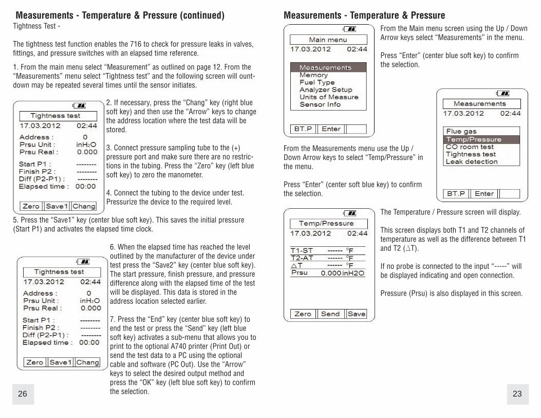
Measurements - Temperature & Pressure (continued)Tightness Test -
The tightness test function enables the 716 to check for pressure leaks in valves,fittings, and pressure switches with an elapsed time reference.
1. From the main menu select “Measurement” as outlined on page 12. From the“Measurements” menu select “Tightness test” and the following screen will ount-down may be repeated several times until the sensor initiates.
2. If necessary, press the “Chang” key (right bluesoft key) and then use the “Arrow” keys to changethe address location where the test data will bestored.
3. Connect pressure sampling tube to the (+)pressure port and make sure there are no restric-tions in the tubing. Press the “Zero” key (left bluesoft key) to zero the manometer.
4. Connect the tubing to the device under test.Pressurize the device to the required level.
5. Press the “Save1” key (center blue soft key). This saves the initial pressure(Start P1) and activates the elapsed time clock.
6. When the elapsed time has reached the leveloutlined by the manufacturer of the device undertest press the “Save2” key (center blue soft key).The start pressure, finish pressure, and pressuredifference along with the elapsed time of the testwill be displayed. This data is stored in theaddress location selected earlier.
7. Press the “End” key (center blue soft key) toend the test or press the “Send” key (left bluesoft key) activates a sub-menu that allows you toprint to the optional A740 printer (Print Out) orsend the test data to a PC using the optionalcable and software (PC Out). Use the “Arrow”keys to select the desired output method andpress the “OK” key (left blue soft key) to confirmthe selection.26
Measurements - Temperature & Pressure
23
From the Main menu screen using the Up / DownArrow keys select “Measurements” in the menu.
Press “Enter” (center blue soft key) to confirmthe selection.
From the Measurements menu use the Up /Down Arrow keys to select “Temp/Pressure” inthe menu.
Press “Enter” (center soft blue key) to confirmthe selection.
The Temperature / Pressure screen will display.
This screen displays both T1 and T2 channels oftemperature as well as the difference between T1and T2 (DT).
If no probe is connected to the input “-----” willbe displayed indicating and open connection.
Pressure (Prsu) is also displayed in this screen.

Measurements - Temperature & Pressure (continued)
Measuring Temperature -
1. Ensure you have a 'K' type probe connected to one or both of the thermo-couple sockets T1 / T2 (refer to figure below)
WARNING: - There is ONLY one correct way to connect the 'K' type thermo-couple plug into the socket (see page 7). Forcing the plug into the socket thewrong way may result in damage to the instrument.
2. Touch the temperature probe to the item under test and read the displayedtemperature.
24
Other Features:
• Pressing “Send” (center blue soft key) acti-vates a sub-menu and allows information to besent to the optional A740 infrared printer or to aPC using the optional USB interface cable andsoftware.
• Pressing “Save” (right blue soft key) activatesa sub-menu that allows the screen data to besaved in a memory location (0 to 99) for laterretrieval.
• Pressing “Zero” (left blue soft key) zeros themanometer. This is used prior to measuringpressure.
NOTE: Analyzer shown in picture above with optional secondGK11M probe. Analyzer ships with one GK11M as standard.
Measurements - Temperature & Pressure (continued)
Measuring Pressure -
1. Ensure you have Pressure Sampling Tube connected to one or both of thePressure Ports and there are no restrictions in the tubing (see figure below)
2. Zero the display by pressing the “Zero” Key (left blue soft key).3. Connect the tube(s) to the device under test and read the pressure on the
display.
The 716 incorporates a differential manometer. Pressure applied to the (-) port issubtracted from the pressure applied to the (+) port. Examples of pressuresbeing measured: (+) port = 10”H2O, (-) port = Not Connected, Displayed reading = 10”H2O(+) port = 10”H2O, (-) port = 5”H2O, Displayed reading = 5”H2O
25
Other Features:
• Pressing “Send” (center blue soft key) acti-vates a sub-menu and allows information to besent to the optional A740 infrared printer or to aPC using the optional USB interface cable andsoftware.
• Pressing “Save” (right blue soft key) activatesa sub-menu that allows the screen data to besaved in a memory location (0 to 99) for laterretrieval.
• Pressing “Zero” (left blue soft key) zeros themanometer. This is used prior to measuringpressure.