
Flue Gas Analysis Computer Type: MULTILYZER STx Read manual before use! ... 5.4 Leakage test of the...
90
SYSTRONIK Elektronik u. Systemtechnik GmbH Gewerbestrasse 57 D-88636 Illmensee Tel.: +49 (0) 7558 / 9206-0 Fax: +49 (0) 7558 / 9206-20 E-Mail: [email protected] Internet: www.systronik.com Read manual before use! Observe all safety information! Keep manual for future use! 04.2018 524271 Instruction Manual Flue Gas Analysis Computer Type: MULTILYZER ® STx
Transcript of Flue Gas Analysis Computer Type: MULTILYZER STx Read manual before use! ... 5.4 Leakage test of the...

SYSTRONIK Elektronik u. Systemtechnik GmbH Gewerbestrasse 57 D-88636 Illmensee Tel.: +49 (0) 7558 / 9206-0 Fax: +49 (0) 7558 / 9206-20 E-Mail: [email protected] Internet: www.systronik.com
Read manual before use!
Observe all safety information!
Keep manual for future use!
04.2018 524271
Instruction Manual
Flue Gas Analysis Computer Type: MULTILYZER® STx

MULTILYZER® STx

MULTILYZER® STx 3
Contents
1 About this instruction manual .................................................................................. 5 1.1 Warning Terms ............................................................................................. 5 1.2 Explanation of symbols and typeface ........................................................... 5
2 Safety ....................................................................................................................... 6 2.1 Intended use ................................................................................................. 6 2.2 Incorrect use ................................................................................................. 6 2.3 Safe handling ............................................................................................... 6 2.4 Qualification of personnel ............................................................................. 7 2.5 Calibration .................................................................................................... 7 2.6 Modifications to the product ......................................................................... 7 2.7 Usage of spare parts and accessories ......................................................... 7 2.8 Liability information ....................................................................................... 7
3 Product description .................................................................................................. 8 3.1 Control panel ................................................................................................ 8 3.2 Package contents ......................................................................................... 9 3.3 Measurement and calculation parameters ................................................. 10 3.4 Measuring methods .................................................................................... 11 3.5 Technical specifications ............................................................................. 13 3.6 Calculation formulae (extract) .................................................................... 17 3.7 Approvals, tests and conformities .............................................................. 18
4 Transportation and storage ................................................................................... 19
5 Commissioning ...................................................................................................... 20 5.1 Connection diagram ................................................................................... 20 5.2 Use of the IR-printer ................................................................................... 21 5.3 Use of the Bluetooth Smart printer ............................................................. 22 5.4 Leakage test of the flue gas probe (Option) ............................................... 24
6 Operation ............................................................................................................... 25 6.1 Menu structure ........................................................................................... 25 6.2 Measuring mode ......................................................................................... 29 6.3 Generate QR-CODE. ................................................................................. 33 6.4 Data Logger function (Option) .................................................................... 33 6.5 Fluegas measurement program ................................................................. 36 6.6 CO-Measurement program ........................................................................ 43 6.7 Temperature-Measurement program ......................................................... 46 6.8 "Pressure / Draft measurement" program .................................................. 49 6.9 Pressure Loss / Let-By / Tightness Test program ..................................... 53 6.10 "Leakage measurement" program (option) ................................................ 55 6.11 "Leakage rate measurement" program (option) ......................................... 57

MULTILYZER® STx
6.12 Pitot Measurement program .......................................................................63
7 Settings configuration menu ..................................................................................65 7.1 Set Time / Date ...........................................................................................66 7.2 Set Display .................................................................................................66 7.3 Set Favorite button .....................................................................................69 7.4 Set Sound Levels .......................................................................................69 7.5 Show device information ............................................................................70
8 Memory mode & memory structure .......................................................................71 8.1 Create a customer database ......................................................................71 8.2 Use of the memory .....................................................................................76 8.3 Enter the user's address .............................................................................79
9 Battery management .............................................................................................80 9.1 Battery mode/charging mode .....................................................................80 9.2 Charging the batteries ................................................................................80
10 Maintenance ..........................................................................................................81
11 Troubleshooting .....................................................................................................82
12 Shutting down and disposal ...................................................................................83
13 Spare parts and accessories .................................................................................84
14 Warranty ................................................................................................................85
15 Copyright ................................................................................................................85
16 Customer satisfaction ............................................................................................85
17 Addresses ..............................................................................................................85
18 Certification ............................................................................................................86 18.1 DIN EN 50379-Certificate ...........................................................................86 18.2 Option: „Dust measurement“ (Emission-measurement) .............................87

MULTILYZER® STx 5
1 About this instruction manual This instruction manual is part of the product.
Read this manual before using the product.
Keep this manual during the entire service life of the product and always have it readily available for reference.
Always hand this manual over to future owners or users of the product.
1.1 Warning Terms
WARNING TERM
The type and source of danger is shown here.
Precautions to take in order to avoid the danger are shown here.
There are three different levels of warning:
Warning term Meaning
DANGER Imminent danger!
Failure to observe the information will result in
death or serious injuries.
WARNING Possible imminent danger!
Failure to observe the information may result in
death or serious injuries.
CAUTION Dangerous situation!
Failure to observe the information may result in
minor or serious injuries as well as damage to
property.
1.2 Explanation of symbols and typeface
Symbol Meaning
m Prerequisite for an activity
Activity consisting of a single step
1. Activity consisting of several steps
Result of an activity
Bulleted list
Text Indication on a display
Highlighting Highlighting

MULTILYZER® STx
2 Safety
2.1 Intended use The flue gas analysis computer MULTILYZER® STx is exclusively suitable for:
Professional settings and control measurements at all small combustion systems (low temperature and burner value boilers and thermal systems) for gas, oil and solid fuel systems.
Any use other than the application explicitly permitted in this instruc-tion manual is not permitted.
2.2 Incorrect use The MULTILYZER® STx flue gas analysis computer must never be used in the following cases:
Hazardous area (Ex) If the device is operated in hazardous areas, sparks may cause deflagrations, fires or explosions
Use as a safety (alarm) unit or continuous measuring device
Ambient air monitoring
Use in humans and animals
2.3 Safe handling This product represents state-of-the-art technology and is made ac-cording to the pertinent safety regulations. Each device is subjected to a function and safety test prior to shipping.
Operate this product when it is in perfect condition. Always ob-serve the operating instructions, all pertinent local and national directives and guidelines as well as the applicable safety regula-tions and directives concerning the prevention of accidents.
Perform an overall visual inspection of the measuring device (including any accessories) prior to each operation of the MULTILYZER® STx in order to ensure proper operation of the device.
Protect the product against impact
Use the product only indoor
Insulate the product from moisture
WARNING
Severe burns or death due to live parts.
Do not touch live parts with the instrument or sensors.

MULTILYZER® STx 7
2.4 Qualification of personnel The product may only be installed, commissioned, operated, main-tained, shut down and disposed of by qualified, specially trained per-sonnel.
Electrical work may only be carried out by qualified electricians in accordance with local and national regulations.
2.5 Calibration The flue gas analysis computer MULTILYZER® STx have to be cali-brated annually by a recognized, relevant authority.
2.6 Modifications to the product Changes or modifications made to the product by unauthorised per-sons may lead to malfunctions and are prohibited for safety reasons.
2.7 Usage of spare parts and accessories Usage of unsuitable spare parts and accessories may cause dam-age to the product.
Use only the manufacturer’s genuine spare parts and accesso-ries of the manufacturer.
2.8 Liability information The manufacturer shall not be liable in any direct or consequential damage resulting from failure to observe the technical instructions, guidelines and recommendations.
The manufacturer or the sales company shall not be liable for costs or damages incurred by the user or by third parties in the use or application of this device, in particular in case of improper use of the device, misuse or malfunction of the connection, malfunction of the device or of connected devices. The manufacturer or the sales company shall not be liable for damage resulting from any use other than the use explicitly stated in this instruction manual.
The manufacturer shall not be liable for misprints.
MULTILYZER® STx
3 Product description The MULTILYZER® STx flue gas analysis computer is a multiple-function analyser with integrated calculating functions. Measure-ments are in accordance with the general regulations set forth by the German “BImSchV” at all kinds of combustion plants within the framework of the monitoring of exhaust systems.
The MULTILYZER® STx flue gas analysis computer has an infrared printer interface, a Bluetooth® interface (Bluetooth® low energy) and can be fitted with a memory card (MicroSD).
User-friendly, color-coded menus support improved and intuitive op-eration. The individual measuring programs, configuration menus, etc. are assigned distinctive colors.
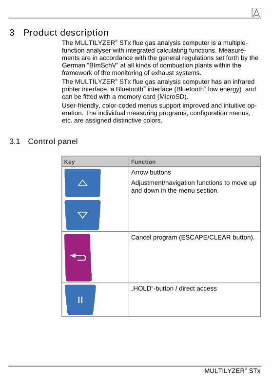
3.1 Control panel
Key Function
Arrow buttons
Adjustment/navigation functions to move up
and down in the menu section.
Cancel program (ESCAPE/CLEAR button).
„HOLD“-button / direct access

MULTILYZER® STx 9
Key Function
Confirm selection (ENTER button).
Switch on and off
„Print“ - button
„Favorite“ - button
3.2 Package contents The Product contains:
Flue gas analysis computer
Protective sleeve with magnet
Flue gas probe with gas treatment and condensate cartridge
Air temperature sensor
Replace filter
USB power-supply
Calibration certificate
Instruction manual

MULTILYZER® STx
3.3 Measurement and calculation parameters
Table 1: Measured Values
Value Measured medium Unit
Tgas Flue gas temperature °C, °F
Tair Air temperature °C, °F
O2 Oxygen concentration Vol.-%
CO Carbon monoxide concentration ppm, mg/m³,
mg/kWh, mg/MJ,
Vol.-%
NO Nitrogen monoxide concentration
(Option)
ppm, mg/m³,
mg/kWh, mg/MJ
SO2 Sulfur dioxide concentration
(Option)
ppm, mg/m³,
mg/kWh, mg/MJ
NO2 Nitrogen dioxide concentration
(Option)
ppm, mg/m³,
mg/kWh, mg/MJ
CO+ Carbon monoxide high (Option) Vol.-%
Draft Draft Pa, hPa, kPa,
mbar, bar,
mmWs, mmHg,
inHg, psi
Barometer Barometric pressure hPa
Table 2: Calculated values
Value Calculated medium Unit
CO2 Carbon dioxide Vol.-%
COref Carbon monoxide referenced to an O2
reference value
ppm
Eta Combustion efficiency value %
Lambda Excess air value
qA Flue gas loss %
Dewpnt Fuel-specific dew point °C, °F
T.Diff Differential temperature (TG - TL) °C, °F
NOx Nitrogen oxide (Option) ppm, mg/m³,
mg/kWh, mg/MJ

MULTILYZER® STx 11
Value Calculated medium Unit
NOref. Nitrogen oxide referenced to an O2
reference value
ppm, mg/m³,
mg/kWh, mg/MJ
NOx ref. Nitrogen oxides referenced to an O2
reference value (Option)
ppm, mg/m³,
mg/kWh, mg/MJ
SO2 ref Sulfur dioxide referenced to an O2
reference value (Option)
ppm, mg/m³,
mg/kWh, mg/MJ
NO2 ref Nitrogen dioxide referenced to an O2
reference value (Option)
ppm, mg/m³,
mg/kWh, mg/MJ
3.4 Measuring methods
Table 3: Measuring procedure
Function Explanation
Temperature meas-
urement
Thermocouple NiCr-Ni (type K)
O2 measurement Electrochemical measuring cell
CO measurement Electrochemical measuring cell
CO+ measurement
(Option)
Electrochemical measuring cell
NO measurement
(Option)
Electrochemical measuring cell
SO2 measurement
(Option)
Electrochemical measuring cell
NO2 measurement
(Option)
Electrochemical measuring cell
Pressure/draft Piezo-resistive sensor with internal tem-
perature compensation
Measuring duration Short-term, stable measurements of max.
60 minutes are possible, followed by a
new calibration phase with ambient air.
Flue gas measurement Via an external water separator and filter,
the flue gas is supplied to the sensors by
means of a gas pump.

MULTILYZER® STx
Function Explanation
Sensor calibration After switching on the instrument, there is
a calibration phase that takes 30 seconds
after a cold start.
CO Sensor protection The standard CO sensor with dynamic H2
compensation is protected automatically
by separate flushing pump. When the
permissible concentration of CO is
reached (>10,000 ppm), the additional
CO pump turns on and flushes the sensor
with fresh air. The measurement starts
again automatically when the CO concen-
tration drop below 8,000 ppm. With an
additional CO+ sensor the flushing pump
will start at 4,000 ppm and stop at 1,600
ppm.
Flue gas sampling Flue gas sampling is done by means of a
probe which enables either a “one-point
measurement” (combi probe) or a “multi-
point measurement” (multi-hole probe).
WARNING
The life of the sensors depends essentially on utilization and use of the instrument. The expected life of the gas sensors is about 24-60 months.

MULTILYZER® STx 13
3.5 Technical specifications
Table 4: Device description
Parameter Value
General Specifications
Dimensions housing
including protective
sleeve (W x H x D)
90 x 53 x 220 mm
(3,6 x 2,1 x 8,7 inch)
Weight (including pro-
tective sleeve)
Ca. 625 g - 685 g (22.05 oz – 24.20 oz)
(depends on count of sensors)
Material Protective
sleeve
Polyamid (PA)
Display High-resolution graphical 3,5“ TFT-
display (240 x 320).
Data communication Infrared printer interface, Bluetooth® in-
terface (Bluetooth® low energy).
Printer External infrared thermal printer
(EUROprinter)
Memory Micro-SD memory card with folder/file
structure
Temperature range
Ambient 0 °C to +40 °C (+32 °F to +104 °F)
Medium 0 °C to +40 °C (+32 °F to +104 °F)
Storage -20 °C to +50 °C (-4 °F to +122 °F)
Air pressure range
Ambient 750 hPa to +1100 hPa
Humidity range
Ambient 20 % rH to 80 % rH
Power supply
Rechargeable battery Lithium-Ion-Battery 3,6 V / 2900 mAh
Power adapter USB power supply
Electrical guard
Protection type IP 42 EN 60529

MULTILYZER® STx
Electromagnetic compatibility (EMC)
Interference DIN EN 55022 (VDE 0878-22)
Noise immunity DIN EN 61000-4-3 (VDE 0847-4-3)
ESD DIN EN 61000-4-2 (VDE 0847-4-2)
Table 5: Device specifications
Parameter Value
Flue gas temperature measurement (T1, T2 and T3)
Measuring range 0 °C to +1000 °C
Max. deviation ± 1 °C (0 °C to +300 °C)
± 1.0 % of measured value (above +300 °C)
Resolution 0.1 °C
Sensor Thermocouple NiCr-Ni (type K)
Combustion air temperature
Measuring range -20 °C to +200 °C
Max. deviation ± 3 °C + 1 digit (-20 °C to 0 °C)
± 1 °C + 1 digit (0 °C to +200 °C)
Resolution 0.1 °C
Sensor Thermocouple NiCr-Ni (type K)
Draft / pressure measurement
Measuring range ± 70 hPa (Draft) / ± 150 hPa (Diff.-Pressure)
Max. deviation ± 2 Pa + 1 Digit (<2.00 hPa)
± 1 % reading (>2.00 hPa)
Resolution ± 0.01 hPa respectively 1 Pa
Sensor Semiconductor sensor

MULTILYZER® STx 15
Pitot measurement
Measuring range 0.5 - 70 m/s
Max. deviation ±0.8 m/s
Resolution 0.1 m/s
Sensor Semiconductor sensor
O2-measurement
Measuring range 0.0 Vol. % to 21.0 Vol. %
Max. deviation ± 0.2 Vol. % by volume of measured value
Resolution 0.1 Vol. %
Sensor Electrochemical measuring cell
Response time
(T90)
30 seconds
CO2- determination
Range 0 – CO2max
Max. deviation ±0.2 Vol.%
Resolution 0.1 Vol.%
Sensor calculation from O2 value
Response time
(T90)
30 seconds
CO- measurement (with H2 compensation)
Measuring range 0 ppm to 10,000 ppm (1.0 Vol. %)
Accuracy 5 ppm (to 50 ppm)
5 % of measured value (above 50 ppm)
Resolution 1 ppm
Sensor Electrochemical measuring cell
Response time
(T90)
60 seconds

MULTILYZER® STx
Table 6: Device specifications - options
Parameter Value
NO-measurement
Measuring range 0-5,000 ppm
Accuracy 5 ppm (to 50 ppm)
5 % of measured value
Resolution 1 ppm
Sensor Electrochemical measuring cell
Response time (T90) 60 seconds
COhigh- measurement (without H2 compensation)
Measuring range 0-4.0 Vol.-% (40,000 ppm)
Accuracy 5 % of measured value (± 1 Digit)
Resolution 0.01 Vol.-%
Sensor Electrochemical measuring cell
Response time (T90) 60 seconds
SO2- measurement
Measuring range 0-5,000 ppm
Accuracy 10 ppm (to 200 ppm)
5 % of measured value (ab 200 ppm)
Resolution 1 ppm
Sensor Electrochemical measuring cell
Response time (T90) 60 seconds

MULTILYZER® STx 17
NO2- measurement
Measuring range 0-500 ppm
Accuracy 10 ppm (to 50 ppm)
10 % of measured value (at 50 ppm)
Resolution 1 ppm
Sensor Electrochemical measuring cell
Response time (T90) 60 seconds
3.6 Calculation formulae (extract)
Calculation of the CO2 value
CO2 = CO2 max * (1 - 21
O2) in %
CO2 Calculated carbon dioxide value in %
CO2max Max. CO2 value (fuel-specific) in % by volume
O2 Measured oxygen concentration in %
21 Oxygen concentration of the air in % by volume
Calculation of the flue gas loss
qA = (TG - TA) * (2
2
O21
A
+ B) in %
qA Flue gas loss in %
TG Flue gas temperature in °F or °C
TA Combustion air temperature in °F or °C
A2, B Fuel-specific factors
O2 Measured O2 value
MULTILYZER® STx
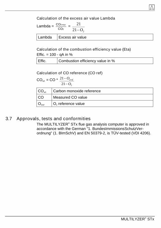
Calculation of the excess air value Lambda
Lambda = 2
max2
CO
CO =
221
21
O
Lambda Excess air value
Calculation of the combustion efficiency value (Eta)
Effic. = 100 - qA in %
Effic. Combustion efficiency value in %
Calculation of CO reference (CO ref)
COref. = CO *
2
2
21
21
O
O ref
COref. Carbon monoxide reference
CO Measured CO value
O2ref O2 reference value
3.7 Approvals, tests and conformities The MULTILYZER® STx flue gas analysis computer is approved in accordance with the German "1. BundesImmissionsSchutzVer-ordnung" (1. BImSchV) and EN 50379-2, is TÜV-tested (VDI 4206).

MULTILYZER® STx 19
4 Transportation and storage
CAUTION
Damage to the device due to improper transportation.
Do not throw or drop the device.
Transporting the device only in the device-specific case.
CAUTION
Damage to the device due to improper storage.
Protect the device from shock when storing it.
Store the device in a clean and dry environment.
Only store the device within the permissible temperature range.
Store the device away from paint, solvent and glue.
MULTILYZER® STx
5 Commissioning
WARNING
Before using the MULTILYZER® STx you have to do a visual inspection of the entire measurement equipment (Device and accessories).For a correct operation of the device.
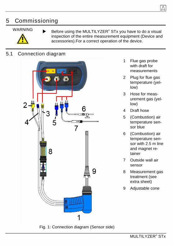
5.1 Connection diagram
1 Flue gas probe
with draft for
measurements
2 Plug for flue gas
temperature (yel-
low)
3 Hose for meas-
urement gas (yel-
low)
4 Draft hose
5 (Combustion) air
temperature sen-
sor blue
6 (Combustion) air
temperature sen-
sor with 2.5 m line
and magnet re-
tainer
7 Outside wall air
sensor
8 Measurement gas
treatment (see
extra sheet)
9 Adjustable cone
Fig. 1: Connection diagram (Sensor side)

MULTILYZER® STx 21
Fig. 2: Connection diagram (Interface side)
5.2 Use of the IR-printer
For printing, the IR interface of the MULTILYZER® STx unit must point towards the printer as shown in the following illustration, keep-ing a minimal distance of ca. 25 cm! (Max. ca. 70 cm).
Fig. 3: Positioning of the MULTILYZER® STx towards the printer
WARNING
Transmission errors if positioning is not correct
The optical transmission zone must be kept straight and free of obstacles!
Ensure Bluetooth printing option is switched off in – Settings-
BluetoothSMART menu for correct IR printer operation.
1 MicroSD-card
holder
2 USB power supply
unit (100-240 V /
50-60 Hz)
3 Speaker
4 IR-Printer-interface
(not visible from
instrument sur-
face)

MULTILYZER® STx
5.3 Use of the Bluetooth Smart printer Measuring Data could be also transferred via Bluetooth Smart to the “Thermoprinter EUROprinter-BLE”. Activate the Bluetooth Smart in the MULTILYZER® STx Settings and on the printer. To activate the Bluetooth Smart on the printer press the keys “OFF” and “ON” at once. A blue flashing LED means activated Bluetooth Smart other-wise the IR modus is activated. The Bluetooth Smart connection be-tween device and printer is described below:

MULTILYZER® STx 23
Select the detected printer to activate the printer.
The IR modus could be set by deactivating the „Bluetooth Printer“ in the settings menu. Set the printer to IR modus as well. Press the keys „OFF“ and „ON“ at once and the blue flashing LED goes out.

MULTILYZER® STx
5.4 Leakage test of the flue gas probe (Option) For Leakage test the complete probe incl. tubes and condensate trap. First tighten both tubes exits and then evacuate the air with a pump ball. The pump ball must not blow up within 20 seconds if the system is tight (under pressure principle).
Fig. 4: Setup of the leak test with the probe leak test set (Art.-Nr.: 511017)

MULTILYZER® STx 25
6 Operation
Switch on device: Briefly press the button.
6.1 Menu structure The menu is divided in different lists: Favourites, Internal, Wireless and System. Switch with the “back arrow” key between the different menu lists.
Favourites: Internal: Wireless: System:
Menu Favourites: On new devices a default favourites list is availa-ble. Measuring programs from the lists Internal, Wireless and System can be activated for the Favourites list. New Favourites programs will occur at the end of the list. Set of factory settings won’t change the favourites list. Set of factory setting with an empty favourites list, will set the default favourites list.
Menu Internal: In this list are all measuring programs which access to the internal sensors.
Menu Wireless: In this list are all measuring programs which connect to the CAPBs.
Menu System: In this list are all System information.
Edit Favourites list In every measuring program in the settings menu is the menu item “In favourites”. If this item is activated the program will occur in the favourites list. Otherwise this program isn’t available in the favourites list.

MULTILYZER® STx
CAPBs product description CAPBs are measuring instruments for different applications. CAPBs can be used to extend BlueLine measuring instruments by the measured variables provided by the CAPBs. The BlueLine measur-ing instrument or an app on a smartphone or tablet display, evaluate and log the measured values. The measured values are transferred via Bluetooth Smart technology.
The following BlueLine measuring instruments can be paired with the CAPBs: BLUELYZER ST, EUROLYZER STx, MULTILYZER STx, S4600 ST series and TMD9.
The various CAPBs allow you to measure pressure, differential pres-sure, flow, temperature and humidity. There are CAPBs for detecting gas leaks and CAPBs to measure air quality.
CAPBs are modular. This way, various sensor modules can be con-nected via different connection types. This results in numerous appli-cation solutions.
Overview
1 LED
2 Multi-purpose key
3 Magnets
4 Unlocking mecha-
nism for removing
CAPBs sens
5 Battery compartment
6 Snap-in mechanism
for CAPBs sens
1
2
3 4
5
6

MULTILYZER® STx 27
LED display
LED status Meaning
Flashing blue The measuring instrument is searching for a Bluetooth Smart connection
Flashing green The measuring instrument is connected
Flashing green, fast Measurement finished, measured data availa-ble, Hold mode
Flashing yellow, fast Settling phase
Flashing yellow Measuring mode
Flashing white Measurement finished, measured data availa-ble
Flashing magenta Data logger active
Flashing red Sensor error
Flashing red, fast Base handle connected, no CAPBs sens plugged in
Flashing magenta, fast Base handle not connected and no CAPBs sens plugged in
Flashing red and beep, every 10 seconds
Low battery
Audible signal (beep)
Depending on the application (GS10, CO30), the CAPBs base handle STm emits audible signals. The audible signal can be activated or deac-tivated in the main menu of the measurement program of the display device.
Modular system with base handle STm The CAPBs constitute a modular system consisting of the universal base handle CAPBs STm and an application-specific sensor module CAPBs sens for a wide variety of measured variables.
The base handle CAPBs STm holds the various sensor modules CAPBs sens. The base handle can be combined with any sensor module to form a complete CAPBs measuring unit. A multi-purpose key is located at the front; it is used for switching the unit on and off, for zero adjustment, for activating the Hold mode or for starting the data logger function. The multi-colour LED displays the status of the CAPBs measuring unit by means of different colours and flashing frequencies.

MULTILYZER® STx
Operation with BlueLine devices
Initial commissioning 1. For switching on, press and hold down for two seconds the multi-
purpose key of the CAPBs device.
2. Start the required CAPBs program on the measuring instrument,
designated by the Bluetooth symbol .
3. Press the "Enter" key to open the main menu in the measure-ment program.
4. Select the Bluetooth Smart search for CAPBs under "Settings Bluetooth SMART".
The Bluetooth Smart search takes approximately 30 seconds. The CAPBs must be on while the search is running. The CAPBs devices found are displayed with serial number of the base handle and the designation of the CAPBs sens.
5. Select the required CAPBs and press the "Enter" key to establish the connection.
When the connection is established, the colour of the LED at the CAPBs LED changes from blue to green. The selected CAPBs is now paired with the BlueLine device. In the future, it will connect au-tomatically. It is sufficient to switch on the CAPBs before you start the required measurement program on the BlueLine device.
CAPBs settings You can assign a function to the key of the multi-purpose key of the CAPBs via the menu item "Settings Bluetooth SMART CAPBs Key". The following functions are available (depending on the meas-urement program): Start/Stop, Hold, Zero, Reset Max/Min and Data Logger (option).
In the Direct Access menu, you can switch between different CAPBs devices via the menu item "CAPB".
MULTILYZER® STx 29
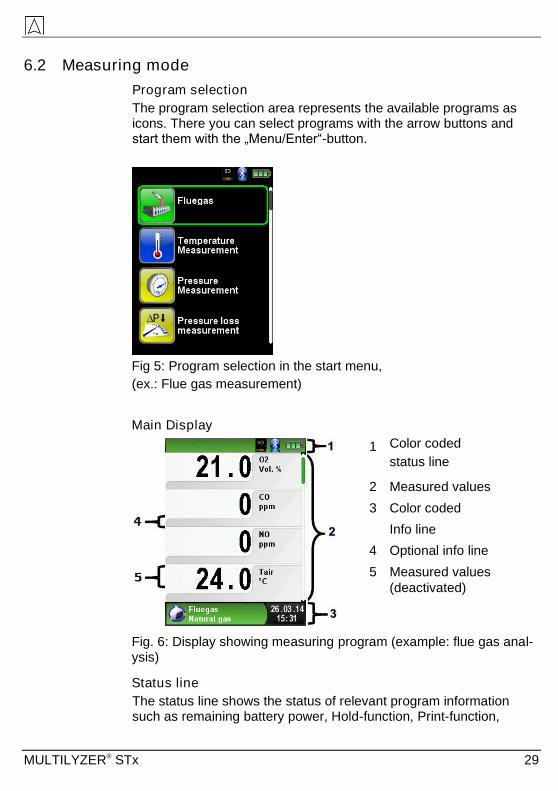
6.2 Measuring mode
Program selection
The program selection area represents the available programs as icons. There you can select programs with the arrow buttons and start them with the „Menu/Enter“-button.
Fig 5: Program selection in the start menu,
(ex.: Flue gas measurement)
Main Display
1 Color coded
status line
2 Measured values
3 Color coded
Info line
4 Optional info line
5 Measured values
(deactivated)
Fig. 6: Display showing measuring program (example: flue gas anal-ysis)
Status line
The status line shows the status of relevant program information such as remaining battery power, Hold-function, Print-function,

MULTILYZER® STx
Bluetooth®-function and operating of the MicroSD-card. The infor-mation displayed depends on the mode and function-specific criteria.
Symbol Bedeutung
MicroSD card in the device
Status battery
Active Bluetooth Smart connection
Inactive Bluetooth Smart connection
Measuring data sending to the EUROprinter
Status CAPBs battery
CAPBs searching
Flue gas temperature lower than dew point temperature
CO flushing pump
Information line
The information line provides details on the time and date, chosen fuel, service messages, etc.
Optional info line
The optional info line gives additional Information about the corre-sponding measured values, ex.: CO2max-values, Min- and Max-values etc.
Measured values (deactivated)
In an unconnected or inactive sensor measuring the corresponding measurement value is displayed in grey.
Main Display
Activate the Main Display with the „Menu-/Enter“-Button.
The Main Display include the main functions of the device.
All other functions respectively settings, are in additional submenus.

MULTILYZER® STx 31
Direct access menu
Print the measured values or Quit Measurement.
Press the "Hold" button to show the direct access menu. The cap-tured values may be either printed or saved in a report on the Mi-croSD card (option). Furthermore you can deactivate HOLD- or stop the measurement and return to the Start menu.
As soon as the print command is chosen, the record is printed paral-lel to the measuring task ( multitasking function), i.e. the meas-urement mode remains active.
Switch off the device.
Briefly press the „On-/Off“-button and confirm with the „Menu/Enter“-Button.

MULTILYZER® STx
Editor
The editor modus is used in different sub menus to set different val-ues, as example: interval time in Data Logger function.
Set interval time in Data Logger function
To change the interval time select “Interval” and start the modifica-tion with the “Enter” button. With the “Arrow-Keys” change the value. To get a zero set “---“. Begin to set the first number.
Than confirm with the “Enter” button and set the second number. Again confirm with “Enter” button and finally set the third number. Confirm the number with “Enter” button.

MULTILYZER® STx 33
6.3 Generate QR-CODE. With the QR-Code the measured values could be transferred to a Tablet or Smartphone. All available QR-Code Apps could be used. The QR-Code function is available for Flue gas, Temperature, Pres-sure and Pitot measurement program.
6.4 Data Logger function (Option) Start Data Logger function.
The function „Data Logger“ is available in different measuring pro-gram in the main menu. The Data Logger will be explained in the pressure menu. Without MicroSD card the Data Logger will not start. The MicroSD card is important to store the logged values.
Open the main menu with the “Enter” button and navigate to “Data Logger” and confirm with “Enter” button.

MULTILYZER® STx
Start the Data Logger with the “Enter” button on “Start Logger”. In the lower field of information the time progress of the logger is shown.
Stop the Data Logger with the “Enter” button on “Stop Logger”.

MULTILYZER® STx 35
The logged values will be stored on the MicroSD card in the folder „LOGGER\Date. File name is the starting time. Every 7200 lines the device will automatically create a new XLM log file. With a logger in-terval of 1 second and a 1 GB MicroSD card it is possible to log in minimum a time period of 2 months.
Set Data Logger interval.
In the editor modus the sampling rate is adjustable between 1 and 999 seconds. The setup is described on page 32.

MULTILYZER® STx
6.5 Fluegas measurement program
Start the "Fluegas" program.
(menu color: green)
After a cold start the calibration phase takes 30 seconds.
After calibration the last fuel used is selected by default and dis-played for confirmation with the “Enter-Button”, another fuel can be selected with the navigation buttons and can be confirmed with the “Enter-Button”.
Switch gas pump off or back on.
When the gas pump is switched off, the pump symbol is no longer shown in the status bar. Changes in the corresponding measured gas values cannot be ruled out, e.g. the O2 value may change as a result of lack of oxygen in the gas lines inside the device. If the gas pump remains off for a longer period of time, calibration in fresh air should be carried out before a new measurement is made.

MULTILYZER® STx 37
Print measurement record (measured values stored with HOLD)
Measured values in HOLD mode can be checked prior to printing. It is also possible to print values recorded in HOLD mode at a later point of time.
As soon as the print command is chosen, the record is printed paral-lel to the measuring task ( multitasking function), i.e. the meas-urement mode remains active.
Start Corestream search.
Small changes in temperature in the combustion air will be shown in form of bars. For constant temperature no bar is visible. The function „Corestream“ is only available in the program „Fluegas“ and for the measurement of the combustion air temperature.
Perform draft measurement (Optional)
To determine the zero point (= initial value in relation to the ambient air pressure), the air hose (with the blue connector) must be un-plugged before each draft measurement. After this, the zero point

MULTILYZER® STx
can be readjusted in case of a deviation from "0.00 hPa". Reconnect the draft hose for measurement and complete the measurement.
The measured draft is displayed continuously in the main display (red colored). After the confirmation of the draft value with “Include Draft” the value will be included in the record and will be displayed in black color.

MULTILYZER® STx 39
Change units.
The units of draft, temperature and gas can be changed as shown in the following pictures.

MULTILYZER® STx
Change O2 Reference.
The desired O2 reference may be changed, as seen on the following images.

MULTILYZER® STx 41
Entering the boiler temperature.
The desired boiler temperature may be changed, as seen on the fol-lowing images.

MULTILYZER® STx
Entering the Smoke No.
The desired Smoke No. may be changed, as seen on the following images.
Entering oil derivate
The oil derivate may be changed, as seen on the following images

MULTILYZER® STx 43
6.6 CO-Measurement program
WARNING
The MULTILYZER® STx is not intended for safety-related meas-urements!
(Power on the device) calibration only in fresh, pollutant- and CO-free ambient, meaning outside of the measurement site!
In case of harmful concentrations of CO immediately take ap-propriate measures: Leave the danger area, ventilation re-spectively provide fresh air, warn endangered people , shut off heater, fix the trouble professionally, etc.
Start the „CO- Measurement “ program.
(menu color: green)
After a cold start the calibration phase takes 30 seconds, then the
CO-Measurement is automatically started.

MULTILYZER® STx
Configure limit value.
The required limit value can be configured within the respective
(nominal) measuring range on a user-specific basis.
If the CO-Value exceeds one of the limits the speaker signals it with an alarm sound. Values exceeding the second limit are displayed in red.
Example:
1. Limit : 30 ppm (Only alarm-sound)
2. Limit : 100 ppm (Alarm-sound and red displayed values)

MULTILYZER® STx 45
Reset the COmax-value.
Acknowledge CO-Alarm.

MULTILYZER® STx
6.7 Temperature-Measurement program
Start "Temperature" program.
(menu color: Blue)
After the start of the program „Temperature“ the measured tempera-ture values and the resulting differential temperature and Min-/ Max-values are shown on the display.
From the main menu you can clear the minimum and maximum val-ues or change the temperature unit.
Reset the Min- and Max-values.

MULTILYZER® STx 47
Change the temperature unit.

MULTILYZER® STx
Print / save protocol, quit measurement.
When you press the "Clear" button the direct access menu appears. The captured values may be either printed or saved in a report on the MicroSD card (option).
Furthermore you can deactivate HOLD- or stop the measurement and return to the Start menu.

MULTILYZER® STx 49
6.8 "Pressure / Draft measurement" program
Start "Pressure" program.
(menu color: yellow)
After starting the program, "Pressure Measurement" at first the au-tomatic zeroing of the pressure sensor will occur, the zeroing phase lasts a few seconds.
After the zeroing, the font of the pressure value changes from grey to black. The black text signals the preparedness of the measuring de-vice. The zeroing of the pressure value can also be run manually from the main menu.
MULTILYZER® STx
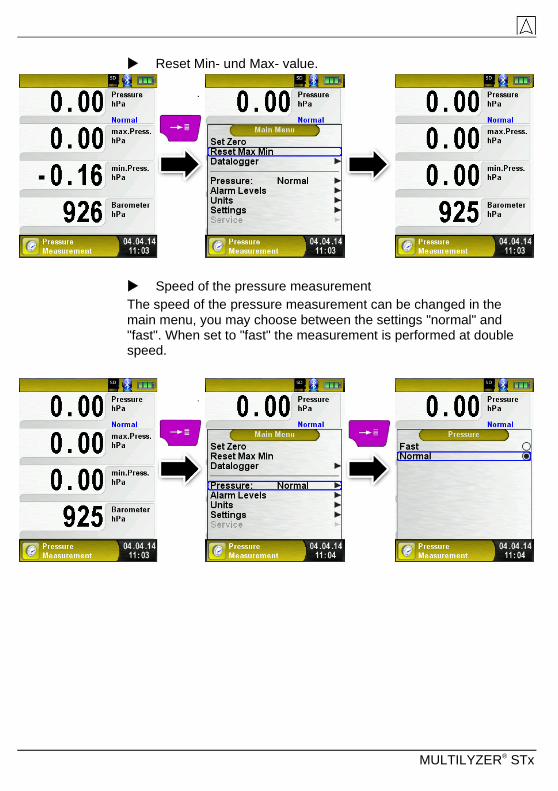
Reset Min- und Max- value.
Speed of the pressure measurement
The speed of the pressure measurement can be changed in the main menu, you may choose between the settings "normal" and "fast". When set to "fast" the measurement is performed at double speed.

MULTILYZER® STx 51
Changing the units
For the pressure measurement there are different units to choose from, as shown in the following illustration.
Configure limit value.
The required limit value can be configured within the respective (nominal) measuring range on a user-specific basis.
If the pressure value exceeds one of the limits the speaker signals it with an alarm sound and the values are displayed in red.

MULTILYZER® STx
Print measurement respectively end measurement.
After pressing the "Clear" button, the Direct Access menu appears. The captured values may be either printed or saved in a report on the MicroSD card (option).
Furthermore, you can disable the HOLD function or stop the meas-urement and return to the Start menu.
As soon as the print command is chosen, the record is printed paral-lel to the measuring task (multitasking function), i.e. the measure-ment mode remains active.

MULTILYZER® STx 53
6.9 Pressure Loss / Let-By / Tightness Test program
Start "Pressure Loss Measurement" program.
(Menu color: yellow)
After starting the program, "Pressure Loss Measurement" at first the automatic zeroing of the pressure sensor will occur, the zeroing phase lasts a few seconds.
After the zeroing, the font of the pressure value changes from grey to black. The black text indicates the device is ready to measure.
Set the Duration Time of the test.
Change the Duration Time using the “Arrow-Keys”.

MULTILYZER® STx
Connect the system with the MULTILYZER® STx.
The gas system must now be connected to the MULTILYZER® STx. Turn on and allow the appropriate pressure into the system.
With "START Pressure Loss." The pressure drop measurement is started. A counter in the main display shows the current running time in seconds and minutes.
After the set elapsed time duration a signal sounds and in the infor-mation line the message "STOP pressure loss" .The elapsed meas-urement time is also displayed. The readings are held in the main display, and you can then print the test report or save it to the Mi-croSD Card.

MULTILYZER® STx 55
6.10 "Leakage measurement" program (option) Starting the "Leakage measurement" program
When you start the "Leakage measurement" program, the pressure sensor is first zero-balanced; this takes a few seconds.
The colour of the pressure value then changes from grey to black. The black colour indicates that the device is ready for measure-ments. Zero balancing can also be performed manually via the main menu.
First set the settling time with the arrow keys.
MULTILYZER® STx
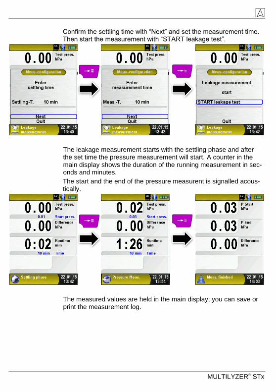
Confirm the settling time with “Next” and set the measurement time. Then start the measurement with “START leakage test”.
The leakage measurement starts with the settling phase and after the set time the pressure measurement will start. A counter in the main display shows the duration of the running measurement in sec-onds and minutes.
The start and the end of the pressure measurent is signalled acous-tically.
The measured values are held in the main display; you can save or print the measurement log.
MULTILYZER® STx 57
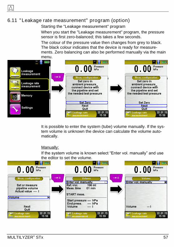
6.11 "Leakage rate measurement" program (option) Starting the "Leakage measurement" program
When you start the "Leakage measurement" program, the pressure sensor is first zero-balanced; this takes a few seconds.
The colour of the pressure value then changes from grey to black. The black colour indicates that the device is ready for measure-ments. Zero balancing can also be performed manually via the main menu.
It is possible to enter the system (tube) volume manually. If the sys-tem volume is unknown the device can calculate the volume auto-matically.
Manually:
If the system volume is known select “Enter vol. manually” and use the editor to set the volume.

MULTILYZER® STx
Automatically:
To identify the system volume connect the candidate system with the device: First connect the shut-off valve (1) with the measurement de-vice. Then connect the plug (2) with the candidate system. Open the shut-off valve (1) and with the pumpball (4) give a pressure (working pressure) to the candidate system. In this example 4.80 hPa.

MULTILYZER® STx 59
Then close the shut-off valve (1) and connect the syringe (3) to the shut-off valve (1). Best case is to connect the already air filled sy-ringe.
With “START meas.” start the measurement. Then open the shut-off valve (1) and add (or minus) the syringe (3) volume. The volume of the SYSTRONIK syringe (3) is 108 ml. Close the shut-off valve (1) and confirm the volume change with “CONFIRM change”. The calcu-lation will start and stop at the entered measuring time automatically.

MULTILYZER® STx
The device shows the calculated volume in the last line. Confirm the volume and exit the calculation menu with the “Back” key.
Set the settling time with the arrow keys, and confirm with “Next”.

MULTILYZER® STx 61
Set the measuring time with the arrow keys, and confirm with “Next”. Then set the working pressure according to the current pressure. A rough estimation of the current value is sufficient. In the next step the measured media must be selected. Available media are air and me-thane.
It is possible either to set the barometric pressure manually or meas-ure by the device. Disselect the item “Manual amb. press.” To acti-vate the automatic measurement by the device.

MULTILYZER® STx
“START meas.” will start the leakage rate measurement with the set-tling phase and after the set time the pressure measurement will start. A counter in the main display shows the duration of the running measurement in seconds and minutes.
The start and the end of the pressure measurent is signalled acous-tically.
The measured values are held in the main display; you can print save, or show the measurement log as QR code.

MULTILYZER® STx 63
6.12 Pitot Measurement program Starting the "Pitot Measurement" program
When you start the "Pitot Measurement" program, the pressure sen-sor is first zero-balanced; this takes a few seconds.
The color of the pressure value then changes from grey to black. The black color indicates that the device is ready for measurements. Zero balancing can also be performed manually via the main menu.
The main display shows the following measured values with adjusta-ble units:
Flow (m/s, km/h)
Volume (m³/h, l/s, m³/s)
Pressure (hPa, mbar, Pa, mmWs, mmHg, inHg)
Barometric pressure (hPa)
For temperature compensation of the Flow value a Type-K Tempera-ture probe must be connected to T2.
Entering measurement data (units, K factor of the Pitot tube, chimney shape, chimney size)
The values entered are used for flow measurement /volume meas-urement.
The menu "Units" allows you to set the units for the flow measure-ment / volume measurement.
The K factor of the Pitot tube can be set via the main menu; the de-fault value is 1.00.
The submenu "Volume" lets you select the chimney shapes "Round" and "Rectangular. If you select the chimney shape "Round", you can set the diameter in mm; if you select the chimney shape "Rectangu-lar, you can set the height and width in mm. If you select the menu

MULTILYZER® STx
item "Deactivated" in the submenu "Shape", volume measurement is hidden in the main display.

MULTILYZER® STx 65
7 Settings configuration menu Open “SETTINGS” configuration menu.
(menu color: purple)
The configuration menu "Settings" can be accessed from the Start menu and in the main menu of the individual measuring programs.
Settings accessible in the „Fluegas“ program.

MULTILYZER® STx
7.1 Set Time / Date Time / date setting change.
For example, to change the month, select the month-line with the ar-row buttons and confirm with the "Menu / Enter" button. The blue line indicates that you can now change the value using the arrow but-tons, use the "Menu / Enter" button to confirm. The device can han-dle leap years and summer-/wintertime.
7.2 Set Display Set display brightness.
Settable are 4 different display brightness: 25%, 50%, 75% and 100%. Depending on brightness the endurance of battery will change.
The intelligent power management of MULTILYZER® STx optimises the battery life.

MULTILYZER® STx 67
The device provides "Eco Mode". The selected setting influences the battery.
Change the displayed size.
There are two different sizes available:
4 lines: Standard setup.
8 lines: Smaller character size will show double count of values.

MULTILYZER® STx
„Autom. Measurement View“ shown in the „Pressure Measurement“ program.
Activate „Zoom Mode“.
The characters of the display will be shown in double size:
„Zoom Mode“ shown in the „Pressure Measurement“ program:

MULTILYZER® STx 69
7.3 Set Favorite button Configure Button Favorite Key.
There are different functions which could be set on the favorite but-ton: Hold, QR-Code, Save, Pump, CO Pump, Datalogger (option) and Draft.
7.4 Set Sound Levels Configure Button Sound and Alarm sound.
There are four sound levels for the touch tone and the alarm tone:
1. Off
2. Low
3. Mean
4. Loud

MULTILYZER® STx
7.5 Show device information Show Info-data.
To show device pending Info-data press the „Pause“-button in the start menu. In the “Diagnose” menu following data will be displayed: Firmware-Version, Release-Date and Serial-Nr.
Show Diagnose-data.
To show Diagnose-data press the „Pause“-button in the start menu. In the “Diagnose” menu following parameters will be displayed:
Battery-voltage, Power-supply-voltage, battery-temperature (in charging mode) and System/Status-code.

MULTILYZER® STx 71
8 Memory mode & memory structure
8.1 Create a customer database Measurements can be saved direct in the customer folder. Every folder has 8 entry lines with 20 characters. The first entry is the key word for the search function in the device. The further lines are for detailed customer information like: Street, City, Email, Phone No…
The customer information will be print out with every measurement print and shown in the protocol.
It is possible to create or modify the customer database either on the MULTILYZER® STx or on a PC.
For first use of the MicroSD card the database should be gener-ated
For new database open menu „Memory“ and choose “Create Data-base”. Confirm the warning “All entries will be deleted” with yes.
With this procedure a file named DATABASE.CSV will be generated on the MicroSD card. This file will show the database entries of the MULTILYZER® STx. This process needs a few seconds.
INFO
Existing Database will be deleted! Private files (images, docu-ments etc.) won’t be deleted!

MULTILYZER® STx
Create / modify customer database on the MULTILYZER® STx
Select „Scan“ in the menu „Memory“ and type the customer name:
Select with the “Arrow-Keys” the row with the desired character. Open the row with the „enter key“ and select the desired character using the “Arrow-Keys”. Select letter by letter in this way:

MULTILYZER® STx 73
Switch between upper and lower case letters and special characters with „<ABC>“. “Delete character“ will delete the last character. With „OK“ save the customer name. Already existing name will be shown. If the name doesn’t exist it is possible to save the customer name with „New entry“.
Now additional information could be saved. (Street, City, Email, and Phone No.):

MULTILYZER® STx
Select „OK“ to save the individual lines. Finally select “Save chang-es” to save all customer information.
To delete customers in the database there mustn’t be any measure-ments stored. Select the customer and choose „Scan“, if there are no measurements stored the request „Entry is empty delete?“ will occur. Confirm the request with “Yes“.
Create / modify customer database on PC
The customer database can be create / modify on the PC as well. Open the file “DATABASE.CSV” on the MicroSD card with the PC. Now type customer information in the table of the “DATABASE.CSV“ file. Column A is the customer name and column B – H are for addi-tional customer information. Don’t use special characters only „@“, „_“ and „.“. Maximum 20 characters per field.

MULTILYZER® STx 75
CAUTION
Incorrect editing of the „DATABASE.CSV“ could generate errors in the MULTILYZER® STx.
Finally save the „DATABASE.CSV“ and restart the MULTILYZER® STx before import the MicroSD card. In this way the database will be newly read.

MULTILYZER® STx
8.2 Use of the memory The use of Micro-SD memory cards as system-independent storage
media ensures maximum flexibility in terms of storing and handling
the measured data. The card can be read without any additional software by all SD-card-enabled data processing systems
(PCs, laptops, notebooks, etc.) using a web browser.
CAUTION
Damage to the MicroSD card slot due to improper use.
Insert the MicroSD card in the device with the contacts show-ing up, as shown in the figure.
The memory structure consists of 1,000 memory entries (customer or location), within every entry 10 measurements protocols can be stored. In total 10,000 measurements can be stored.
At the end of a measurement you can take the measurement proto-col in a free space. The file name is automatically assigned by the device and is structured as follows:
Date and time Type of measurement (ex.: Fluegas)
CAUTION
A file which has been created and saved on the card is protected against manipulation and, if manipulated, can neither be displayed by the device nor printed!
26.05.12-08:41 Fluegas

MULTILYZER® STx 77
You can view the saved file, print or override it with a new measure-ment.
The file name and the storage location is shown in the lower bar. In this example: Storage folder: MEMORY/0000 and file name 0000_01.txt:
The customer information will be shown in the header of the meas-urement report.

MULTILYZER® STx
The saved file can be opened with a web browser (z. B.: Chrome, Firefox, Explorer, Opera, etc.)

MULTILYZER® STx 79
8.3 Enter the user's address To Import the user's address you have to create the file "Address.txt" on the MicroSD-card. This is a pure text file with the file extension .txt. The text file can be created with any editor (ex: Notepad) on a PC. A maximum of 8 lines per 22 characters are possible.
NOTE
An already imported user's address will be overridden!
Copy on
MicroSD card
MULTILYZER® STx
9 Battery management
9.1 Battery mode/charging mode
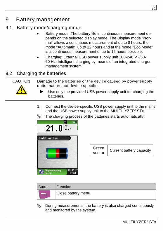
Battery mode: The battery life in continuous measurement de-pends on the selected display mode. The Display mode "Nor-mal" allows a continuous measurement of up to 8 hours, the mode "Automatic" up to 12 hours and at the mode "Eco Mode" is a continuous measurement of up to 12 hours possible.
Charging: External USB power supply unit 100-240 V~/50-60 Hz. Intelligent charging by means of an integrated charger management system.
9.2 Charging the batteries
CAUTION
Damage to the batteries or the device caused by power supply units that are not device-specific.
Use only the provided USB power supply unit for charging the batteries.
1. Connect the device-specific USB power supply unit to the mains and the USB power supply unit to the MULTILYZER® STx.
The charging process of the batteries starts automatically:
Button Function
Close battery menu.
During measurements, the battery is also charged continuously and monitored by the system.
Green
sector Current battery capacity
MULTILYZER® STx 81
As soon as the battery is fully charged and the “Charge Funct.” menu is shown the device switches off automatically, otherwise it switches to passive recharging mode (trickle charging).The “Charge Funct.” menu is no longer shown.
When recharging is finished the charger can remain connected to the MULTILYZER® STx without the battery being damaged.
Service life and capacity of the battery
The MULTILYZER® STx is equipped with a powerful Li-Ion battery. The service life and capacity of the battery are considerably affected by the way the device is charged and used. In order to make han-dling safer, the device features efficient and battery-saving charge management suitable for all applications.
The graphical charge level indicator of the MULTILYZER® STx con-sisting of three elements of a battery symbol helps the user to cor-rectly estimate the capacity of the battery. Five different battery states are detected.
During normal use it is recommended not to recharge the bat-tery until it is run down completely.
The battery can be recharged at any time given that the charge management system recognises the need to recharge the battery. Otherwise, the charge management system will not release the bat-tery for charging.
The service life of the Li-Ion battery is significantly reduced when the device is operated at temperatures below +5 °C.
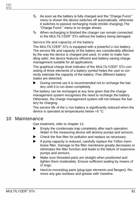
10 Maintenance Gas treatment, refer to chapter 13.
Empty the condensate trap completely after each operation. Water in the measuring device will destroy pumps and sensors.
Check the fine filter for pollution and replace as necessary.
If pump capacity is reduced, carefully replace the Teflon mem-brane filter. Damage to the filter membrane greatly decreases or eliminates the filter function and leads to the failure of expensive pumps and sensors.
Make sure threaded parts are straight when positioned and tighten them moderately. Ensure sufficient sealing by means of O rings.
Hard-to-move/plug parts (plug-type elements and flanges): Re-move any gas residues and grease with Vaseline.

MULTILYZER® STx
Replacing the battery
For technical reasons, old batteries may only be replaced by the manufacturer or an authorised service partner.
Do not short-circuit connection terminals.
To protect the environment, batteries must not be disposed of to-gether with the normal household waste. Return old batteries to the point of purchase or to a collecting point.
11 Troubleshooting Repair work may only be performed by qualified, specially trained staff.
Problem Possible cause Troubleshooting
"CO value too
high"/“CO sensor
defective“ message.
CO sensor mal-
function.
Run device without
accessories in fresh
air. CO measuring
range exceeded.
End of service
life of sensor.
Take device in for
servicing.
Incorrect measured
gas values (e.g.
measured O2 value
too high, CO2 value
too low, no CO val-
ues displayed, etc.).
Leak in measur-
ing system.
Check gas treat-
ment system for
cracks and other
damage.
Check hose system
for cracks and other
damage.
Check O rings of
gas treatment unit.
Check O ring of
external probe pipe.
Service message. Device has not
been inspected
for a longer peri-
od.
Take device in for
servicing.

MULTILYZER® STx 83
Problem Possible cause Troubleshooting
Measured gas values
are displayed slowly.
Filter in the gas
treatment system
is used up.
Check filter and
replace, if neces-
sary.
Hose system
bent.
Check hose system
Gas pump pol-
luted.
Take device to ser-
vice centre.
Flue gas temperature
unstable.
Humidity in the
probe pipe.
Clean probe.
Device automatically
switches off.
Battery empty. Charge battery.
Battery defective. Take device to ser-
vice centre.
Device does not
switch on.
Battery empty. Charge battery.
Take device to ser-
vice center.
No draft value Sensor defect Send the device to
the manufacturer.
Frozen Display – Press „on/off“-key
six seconds
Other malfunctions – Send the device to
the manufacturer.
12 Shutting down and disposal To protect the environment, this device must not be disposed of
together with the normal household waste. Dispose of the de-vice according to the local conditions and directives.
This device consists of materials that can be reused by recycling firms. The electronic inserts can be easily separated and the device consists of recyclable materials.
If you do not have the opportunity to dispose of the used device in accordance with environmental regulations, please contact us for possibilities to return it.

MULTILYZER® STx
13 Spare parts and accessories The gas treatment protect the flue gas analyzer against disturbing components like dust, carbon black and condensate.
The condensate filter cartridge in good condition is a protector for the flue gas analyzer against dirt and an important part of the measure-ment of exhaust gas.
01020305
04070809 06
Articles: Art.-Nr.
Filter spare part package (5x 520921 and 5x
520919)
O ring package for condensate filter cartridge
500208
511002
Spare parts for condensate cartridge:
(01) Inlet piece 520594
(02) Glass piston with arrow 520596
(03) Centre piece with cylinder pieces 521990
(04) Glass piston with logo 521778
(05) Infiltec fine filter 520919
(06) Intermediate piece 520592
(07) Teflon membrane 23.5 mm 520921
(08) O ring 18 x 3 520365
(09) Outlet piece 520591
CAUTION
Check the completeness and functionality of particle filter, filter disc, glass piston and O-rings. After the measurement discon-nect the probe from the analyzer, empty the condensate and exchange used filters!

MULTILYZER® STx 85
14 Warranty The manufacturer's warranty for this product is 12 months after the date of purchase. This warranty shall be good in all countries in which this device is sold by the manufacturer or its authorised deal-ers.
15 Copyright The manufacturer retains the copyright to this manual. This manual may not be reprinted, translated, copied in part or in whole without prior written consent.
We reserve the right to technical modifications with reference to the specifications and illustrations in this manual.
16 Customer satisfaction Customer satisfaction is our prime objective. Please get in touch with us if you have any questions, suggestions or problems concerning your product.
17 Addresses The addresses of our worldwide representations and offices can be
found on the Internet at www.systronik.com

MULTILYZER® STx
18 Certification
18.1 DIN EN 50379-Certificate

MULTILYZER® STx 87
18.2 Option: „Dust measurement“ (Emission-measurement)
Wireless connection to STM 225 (dust measurement device) Open menu “Dust measurement“.
The first connection to any STM 225 needs a device search. The search menu will start by choosing “Select device”:
With “Search New“ the Bluetooth search is activated and all detected devices are listed. Choose the STM 225 and the connected device will be stored by the MULTILYZER® STx automatically. The detected STM 225 will be default device for further measurements. With “Connect“ the MULTILYZER® STx will connect the chosen STM 225 and then flush the device with fresh air automatically.
MULTILYZER® STx
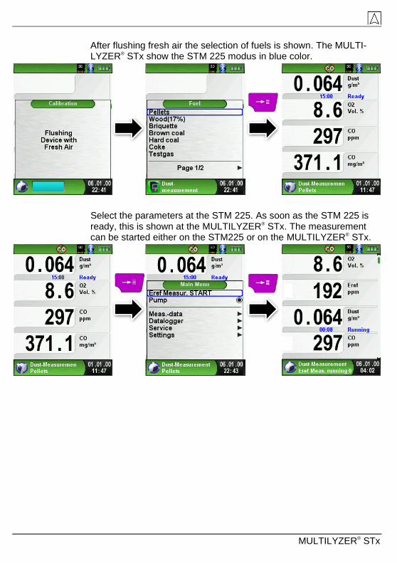
After flushing fresh air the selection of fuels is shown. The MULTI-LYZER® STx show the STM 225 modus in blue color.
Select the parameters at the STM 225. As soon as the STM 225 is ready, this is shown at the MULTILYZER® STx. The measurement can be started either on the STM225 or on the MULTILYZER® STx.

MULTILYZER® STx 89
During the emission measurement the past time is shown in minutes. The measurement stops automatically after 15 minutes. The calcu-lated emission reference values (EBco and EBdst) with the corre-sponding measurement uncertainty (Uco and Udst) are shown. Emission reference values minus measurement uncertainty (EBc-U and EBdst-U) are shown as well. These values can be printed out, saved or transferred to QR-Code.
The emissions are calculated to a 15 minutes average value referred to the 15 minutes O2 average value:
EB = EM *
2
2
21
21
O
OB
EB = Emissions, calculated to the reference O2 value
EM = Measured emissions
O2B = Reference O2
O2 = Measured O2 value
MULTILYZER® STx
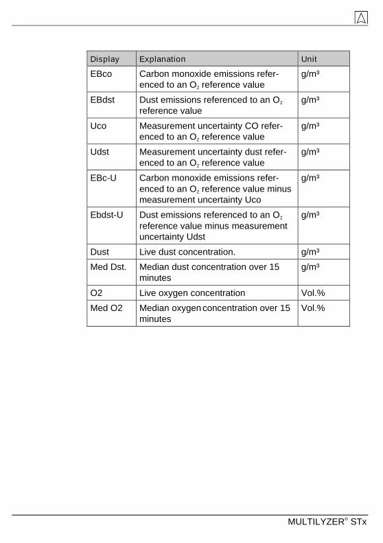
Display Explanation Unit
EBco Carbon monoxide emissions refer-
enced to an O2 reference value
g/m³
EBdst Dust emissions referenced to an O2
reference value
g/m³
Uco Measurement uncertainty CO refer-
enced to an O2 reference value
g/m³
Udst Measurement uncertainty dust refer-
enced to an O2 reference value
g/m³
EBc-U Carbon monoxide emissions refer-
enced to an O2 reference value minus
measurement uncertainty Uco
g/m³
Ebdst-U Dust emissions referenced to an O2
reference value minus measurement
uncertainty Udst
g/m³
Dust Live dust concentration. g/m³
Med Dst. Median dust concentration over 15
minutes
g/m³
O2 Live oxygen concentration Vol.%
Med O2 Median oxygen concentration over 15
minutes
Vol.%


