Fluctuation Measurements in DIII-D Edge Electron...
23
QTYUIOP Edge Electron Temperature Fluctuations in DIII-D - R. D. Lehmer APS97 - 1 Edge Electron Temperature Fluctuation Measurements in DIII-D R. D. Lehmer, J. A. Boedo, R. A. Moyer - UC-San Diego J. G. Watkins - Sandia National Laboratories K. H. Burrell - General Atomics
-
Upload
nguyenlien -
Category
Documents
-
view
217 -
download
0
Transcript of Fluctuation Measurements in DIII-D Edge Electron...

QTYUIOPEdge Electron Temperature Fluctuations in DIII-D - R. D. Lehmer APS97 - 1
Edge Electron Temperature Fluctuation Measurements in DIII-D
R. D. Lehmer, J. A. Boedo, R. A. Moyer - UC-San Diego
J. G. Watkins - Sandia National Laboratories
K. H. Burrell - General Atomics

QTYUIOPEdge Electron Temperature Fluctuations in DIII-D - R. D. Lehmer APS97 - 2
AbstractMeasurements of the electron temperature fluctuations in the edgeof tokamaks have shown that Te fluctuations can not be neglectedwhen determining the cross field heat and particle transport (Liewer,McChesney, Zweben, and Gould, Phys. Fluids 29 (1986) 309). Amodified phase compensated triple probe (Tsui, Bengtson, Li, et al.,Rev. Sci. Instrum. 63 (1992) 4608) is utilized on the existingmidplane reciprocating probe hardware on DIII-D to add phasecorrelated Te fluctuations to the existing measurement of ionsaturation current and floating potential fluctuations. With thistechnique, we are able to infer the cross field conductive heattransport and make better estimates of the particle and convectiveheat transport. The design and implementation of a high-bandwidthtriple probe measurement in a high heat flux, beam-heated tokamakdischarge will be discussed. Preliminary measurements from thediagnostic upgrade will be presented, along with comparisons of theconvective and conductive heat flux estimates up to the separatrixin L- and H- mode plasmas.

QTYUIOPEdge Electron Temperature Fluctuations in DIII-D - R. D. Lehmer APS97 - 3
Goal of Measurement
• To Improve the Understanding of the Cross Field Heat Transport Mechanisms in the Shear Layer and SOL.
Need to Compare Convective vs. Conductive Heat Transport.• Reciprocating Scanning Probe Measurements at DIII-D Have So Far
Neglected Te Fluctuations. - Unable to Infer Conductive Heat Transport.
• Correlated ne, Eθ and Te Fluctuation Measurements are Necessary to Determine Conductive Heat Flux.
• With Correlated Te Fluctuation Measurement, Improved Estimates for Local Particle Transport and Convective Heat Flux can be made.
To Measure the Turbulently Driven Heat Flux in the Edge of DIII-D

QTYUIOPEdge Electron Temperature Fluctuations in DIII-D - R. D. Lehmer APS97 - 4
Turbulently Driven Heat Fluxes are Determined from the Correlation of ne, Te, and Eθ
Ref: Liewer, McChesney, Zweben, and Gould, Phys. Fluids 29 (1986) 309
˜ Q tot = ˜ Q conv + ˜ Q cond
Q Tconv e r= 52
Γ
Γr nE B= ˜ ˜ /θ φ˜ ˜E pθ θφ= −∇
˜ φ p = ˜ φ f + α ˜ T e
˜ Q cond =5
2n ˜ T e
˜ E θ / Bφ
˜ n
n=
˜ I sat
Isat
+˜ T eTe
ConvectiveHeat Flux
ConductiveHeat Flux
Measured and First Order Inferred Quantities
Te Fluctuations Measurement Allows for Red Terms to be Estimated.

QTYUIOPEdge Electron Temperature Fluctuations in DIII-D - R. D. Lehmer APS97 - 5
Probe Methods Considered for Determining the Heat Flux in the Edge of DIII-D
• Fast Swept Probes (TJ-I, TEXT):For DIII-D: Requires ~1-3kW RF amplifier (@1-2MHz)Fit Probe Characteristics with very few points (5-10)
• Triple Probe Method (TEXT, TEXT-U, Phaedrus-T, and TBR):Passive - Requires No Sweeping or Voltage Tracking; Ease of Analysis.Capacitance Problems in DIII-D Preclude Its Use at High Frequencies (>10kHz).
• Second Harmonic Detection (TEXTOR):Uses 1kW Power Amplifier; Transmission Line Eliminates Capacitance Effects.Non-Linear Behavior about Vf Determines Amplitude of Te Fluctuations.

QTYUIOPEdge Electron Temperature Fluctuations in DIII-D - R. D. Lehmer APS97 - 6
Triple Probe Technique Will Not Work at DIII-D Because of the Construction of the Probe
• Triple Probe Technique Compares the Fluctuating Floating Potential to the Potential Fluctuations on One Tip on a Biased Double Probe.
• Triple Probe Techniques Work in Smaller Tokamaks (TEXT, TBR, etc), but Large Parasitic Capacitance in UCSD/SNLA Scanning Probe Causes Rolloff (30kHz).
• Probe Head and Drive Tube not Designed to Measure Fluctuating Potential and Current Simultaneously on the Same Pin.
• This Technique Would Require Major Vacuum Hardware Redesign.
I+
I-
Ip
Rp
Ip
V’1
Isat
V2
50Ω100kΩ
50Ω
300pF
Probe

QTYUIOPEdge Electron Temperature Fluctuations in DIII-D - R. D. Lehmer APS97 - 7
Second Harmonic Detection System for UCSD/SNLA Scanning Probe at DIII-D
• Floating Single Probe.• Driven at 400kHz to Approximately 0.5Te About Vf.• Non-Linear Response to Sweeps About Vf Generates Harmonics
in Collected Current. • Current is Analog Filtered at 1st and 2nd Harmonics (800kHz).
Bandwidth for Te Fluctuations will be About 200kHz.• Expansion of Idealized Probe Characteristic about Vf Relates Ratio
of Current in Harmonics to the Electron Temperature (for U0 < Te). First Order Solution is Te = U0(Iω/4I2ω).

QTYUIOPEdge Electron Temperature Fluctuations in DIII-D - R. D. Lehmer APS97 - 8
Schematic Diagram of Second Harmonic Detection System Power Components
50Ω
Transmission Line
MachineGround
Dummy Transmission Linefor Balanced Circuit Operationwith No Plasma.
SignalTransformer
Power Amplifier1kW Max@ 400kHz
Currentto Filters
ProbeTip
Improvement of Design Previously Used by UCSD at TEXTOR Tokamak(J. Boedo, et al., to be Submitted to RSI)

QTYUIOPEdge Electron Temperature Fluctuations in DIII-D - R. D. Lehmer APS97 - 9
Current Status: Interim Check-Out Phase
• If Balanced Circuit Design Works with Plasma, We Can Determine Average <Te> from Harmonic Detection and Compare to Equilibrium Te from Double Probe.
• Temporary Installation of Existing Power Amplifier and Electronics in Existing Isolated Rack for Scanning Probe for Up Coming Operations Period.
• In this Arrangement, Excessive Cable Lengths Will Make Correlated Fluctuation Measurements and Heat Flux Estimates Difficult - not Part of the Interim Check-Out Goals.
Goal: Test Power Supply Capacity and Balanced Circuit Design.

QTYUIOPEdge Electron Temperature Fluctuations in DIII-D - R. D. Lehmer APS97 - 10
Upgrade Scheduled to be Complete in March, ‘98

QTYUIOPEdge Electron Temperature Fluctuations in DIII-D - R. D. Lehmer APS97 - 11
Harmonic Detection System at DIII-D Will Incorporate Several Improvements
• Improvements:– Power Supply Feedback System– New 1kW Power Supply– New Electronics (Adjustable Gains, Increased Filter Bandwidth)
• Other Upgrades:– Vacuum System Upgrade (New Pump and Controls)– Piggyback Electronics Box
QTYUIOPEdge Electron Temperature Fluctuations in DIII-D - R. D. Lehmer APS97 - 12
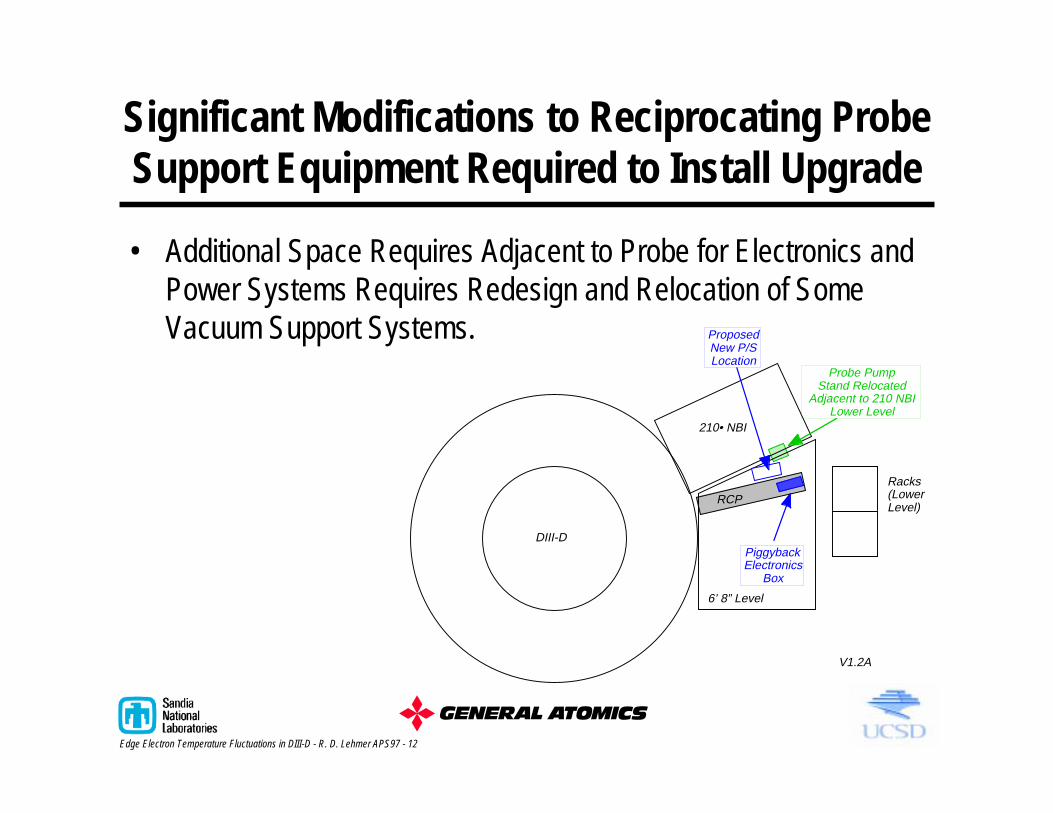
Significant Modifications to Reciprocating Probe Support Equipment Required to Install Upgrade
• Additional Space Requires Adjacent to Probe for Electronics and Power Systems Requires Redesign and Relocation of Some Vacuum Support Systems.
210• NBI
RCP
6’ 8” Level
Racks(LowerLevel)
ProposedNew P/SLocation
Probe PumpStand Relocated
Adjacent to 210 NBILower Level
DIII-DPiggybackElectronics
Box
V1.2A
QTYUIOPEdge Electron Temperature Fluctuations in DIII-D - R. D. Lehmer APS97 - 13
I2ω
Iω
UoMPY100
SRS235400kHz
Funct. Gen.(-14dBm)
ENI2100LPowerAmp.
(50dBm)
200HzLowpass
Z2
X1
OUT
AMMod.
-1.25VY1
REF10
80k10k
-+
-+
Fire Probe - Resets Integrator
-+
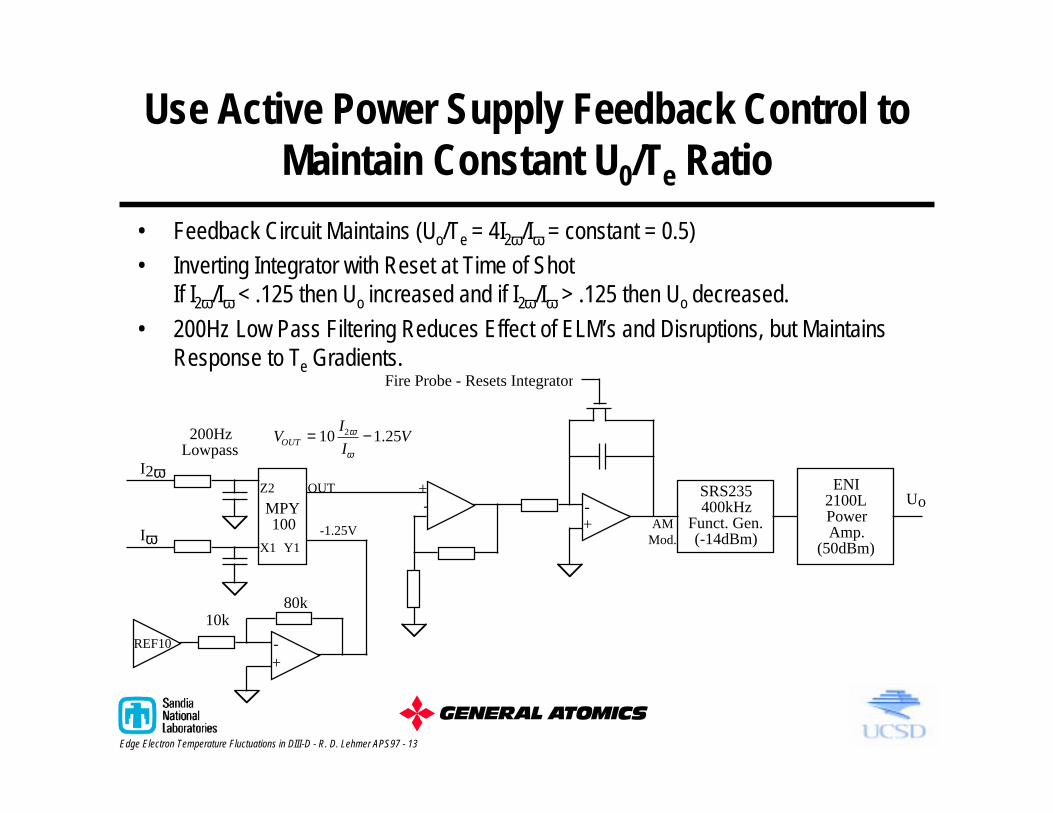
Use Active Power Supply Feedback Control to Maintain Constant U0/Te Ratio
VI
IVOUT = −10 1 252ω
ω
.
• Feedback Circuit Maintains (Uo/Te = 4I2ω/Iω = constant = 0.5)• Inverting Integrator with Reset at Time of Shot
If I2ω/Iω < .125 then Uo increased and if I2ω/Iω > .125 then Uo decreased.
• 200Hz Low Pass Filtering Reduces Effect of ELM’s and Disruptions, but Maintains Response to Te Gradients.

QTYUIOPEdge Electron Temperature Fluctuations in DIII-D - R. D. Lehmer APS97 - 14
Harmonic Detection System is not a Permanent Replacement for Base Electronics Package
• Swept Double Probe Measurement is Still the Primary Method of Determining Equilibrium Te and ne Profiles.
• Plug Compatible Systems - Allows Switch of Diagnostic Capabilities During a Pit Run.
DetachableElectronics Box
StandardElectronics Box
MezzanineLevel

QTYUIOPEdge Electron Temperature Fluctuations in DIII-D - R. D. Lehmer APS97 - 15
Comparison Studies of RMS Level of Te from Harmonic Detection and Te from Double Probe
• Conduct Preliminary Tests in Piggyback Mode on Non-Critical Run Days.• Interim Test Configuration: Replace Turbulent Isat Measurement with Te
Measurement and Retain Double Probe Capability.
B
Isat~ Vf
~
Swept Tipfor Te
Spare
B
~ Vf~Swept Tip
for Te
DoubleProbe Tips
Arrangement for Comparison Studies Normal Operating Arrangement with Te
QTYUIOPEdge Electron Temperature Fluctuations in DIII-D - R. D. Lehmer APS97 - 16
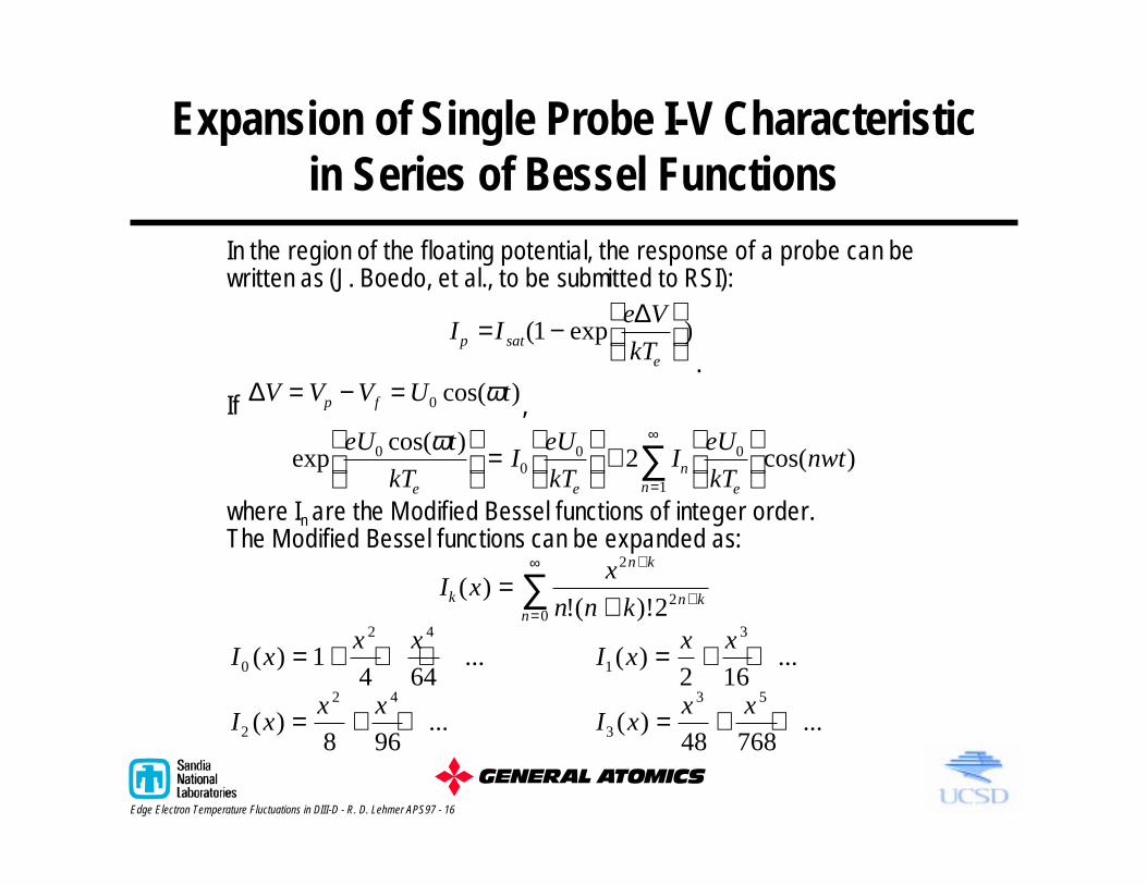
Expansion of Single Probe I-V Characteristic in Series of Bessel Functions
In the region of the floating potential, the response of a probe can bewritten as (J. Boedo, et al., to be submitted to RSI):
I Ie V
kTp sate
= −
( exp )1∆
.
If ∆V V V U tp f= − = 0 cos( )ω ,
expcos( )
cos( )eU t
kTI
eU
kTI
eU
kTnwt
e en
en
00
0 0
1
2ω
=
+
=
∞
∑where In are the Modified Bessel functions of integer order.The Modified Bessel functions can be expanded as:
I xx
n n kk
n k
n kn
( )!( )!
=+
+
+=
∞
∑2
20 2
I xx x
0
2 4
14 64
( ) ...= + + + I xx x
1
3
2 16( ) ...= + +
I xx x
2
2 4
8 96( ) ...= + + I x
x x3
3 5
48 768( ) ...= + +

QTYUIOPEdge Electron Temperature Fluctuations in DIII-D - R. D. Lehmer APS97 - 17
For Sweep Amplitudes Smaller than Te, Ratio of Bessel Functions can be Reduced to Simple Form
Given that
I xx x
0
2 4
14 64
( ) ...= + + + I xx x
1
3
2 16( ) ...= + +
I xx x
2
2 4
8 96( ) ...= + + I x
x x3
3 5
48 768( ) ...= + +
if x<<1, then (J. Boedo, et al., to be submitted to RSI):I x
I x
x2
1 4
( )
( )=
and
I x
I x
x3
1
2
24( )( )
=
Therefore, if x = eU0/kTe = 0.5, then Second Harmonic in CurrentResponse to Sweep will be about 10% of the Fundamental Harmonicand the Third Harmonic will be about 1% of the Fundamental.
QTYUIOPEdge Electron Temperature Fluctuations in DIII-D - R. D. Lehmer APS97 - 18
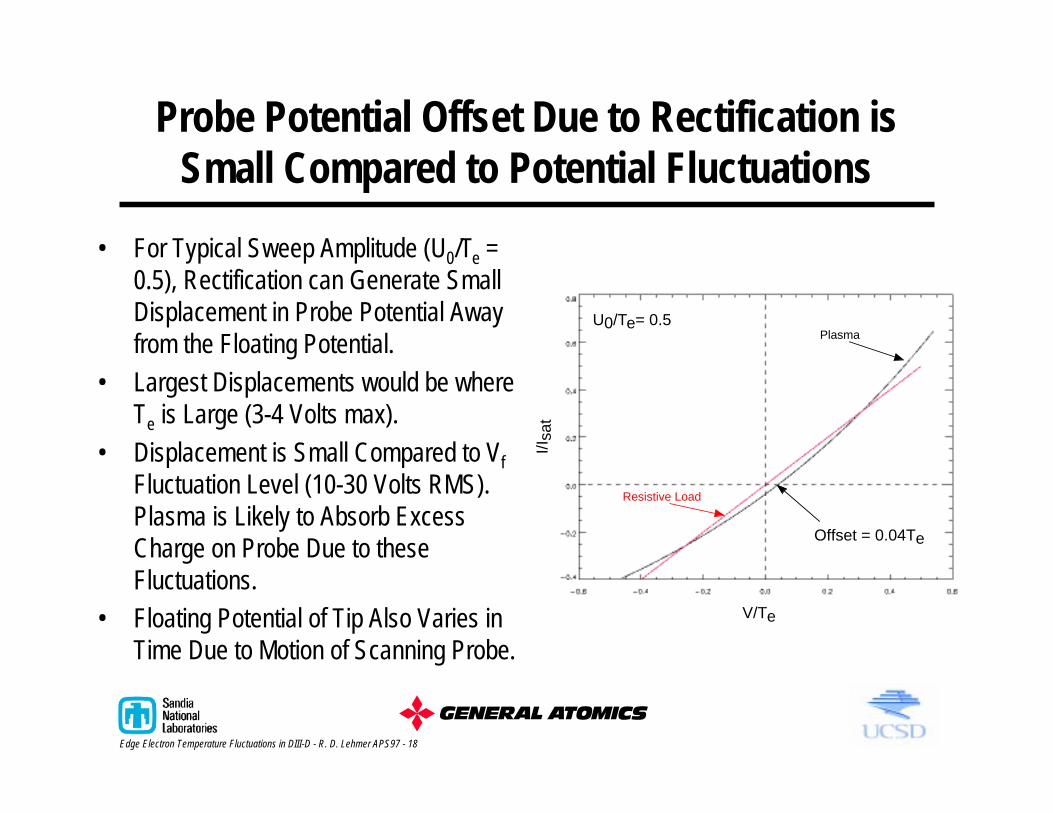
Probe Potential Offset Due to Rectification is Small Compared to Potential Fluctuations
• For Typical Sweep Amplitude (U0/Te = 0.5), Rectification can Generate Small Displacement in Probe Potential Away from the Floating Potential.
• Largest Displacements would be where Te is Large (3-4 Volts max).
• Displacement is Small Compared to Vf Fluctuation Level (10-30 Volts RMS). Plasma is Likely to Absorb Excess Charge on Probe Due to these Fluctuations.
• Floating Potential of Tip Also Varies in Time Due to Motion of Scanning Probe.
V/Te
I/Isa
t
U0/Te= 0.5
Offset = 0.04Te
Plasma
Resistive Load

QTYUIOPEdge Electron Temperature Fluctuations in DIII-D - R. D. Lehmer APS97 - 19
• Bulk of Turbulent Particle Flux is Observed to Occur Below 200kHz.
• Electron-Electron Collision Rate Places an Upper Limit on the Rate that the Electron Energy Distribution can Respond.
• For Typical DIII-D Edge/SOL Parameters:
Electrostatic Fluctuations Responsible for Turbulent Particle Flux are much Slower than νee.
νee
e
xn
T= 2 9 106
32
.ln Λ
νee x x s=( )( )
( )= −2 9 10
10 10
301 5 106
136 1
32
. .
QTYUIOPEdge Electron Temperature Fluctuations in DIII-D - R. D. Lehmer APS97 - 20
FILTER
BANDPASS
400KHZ
50Ω20Ω
1KΩ 1KΩ
50Ω 250Ω
50Ω50Ω
FILTER
BANDPASS
800KHZ
50Ω20Ω
1KΩ 1KΩ
50Ω 105Ω
50Ω50Ω
ENI250WAMP50db
50Ω Out
Probe
31mA500K
100K
1K
160pf
3.3V FastHigh VoltageClamp CKT.
1K
31mA500K
100K
1K
160pf
3.3V FastHigh VoltageClamp CKT.
1K
1K
1K
20Ω
PeakDetector
PeriodicSample &Hold Timing Circuit
PeakDetector
PeriodicSample &Hold Timing Circuit
PeakDetector
PeriodicSample &Hold Timing Circuit
20Ω
20Ω
20Ω
Z
To A/D
Z
To A/D
Z
To A/D
50Ω
50Ω
50Ω
4
15
78
4
15
78In
626
2
Out 35
6
4
15
78
4
15
78In
626
2
Out 38
3
4
15
78
4
5
7
26
3
11
26
4
5
78
WCCW
6
CW
WW
3CCWCW
CCW
WCW
2
CCW
CWW
CW
8
CCW1
3
3
3
9
2
* Not e : Inpu t A/ D is 1MΩ to avoid signal l eve l att enuated.
4
1V per Amp
OverAl l
Ove rAl l
OverAl l
9 Td=1.25us
7
1 0Khz -> 1 2Mhz
Pr obe T ip
Tokamak GND
1. Td=0
2. Td=0Av=0.10 7
Vd iv ide r
3. Td=2.5us
Td=2.5usAv=0.1 05
6. Td=2.5us
4. Td=-0.40 4us
5. Td=5.0 95us
8. Td=5.08us7. Td=-0 .276us
(4 00KHz)Td=7.1 91usAv=2 1.6
(80 0KHz)Td=6.05 4usAv=50.4
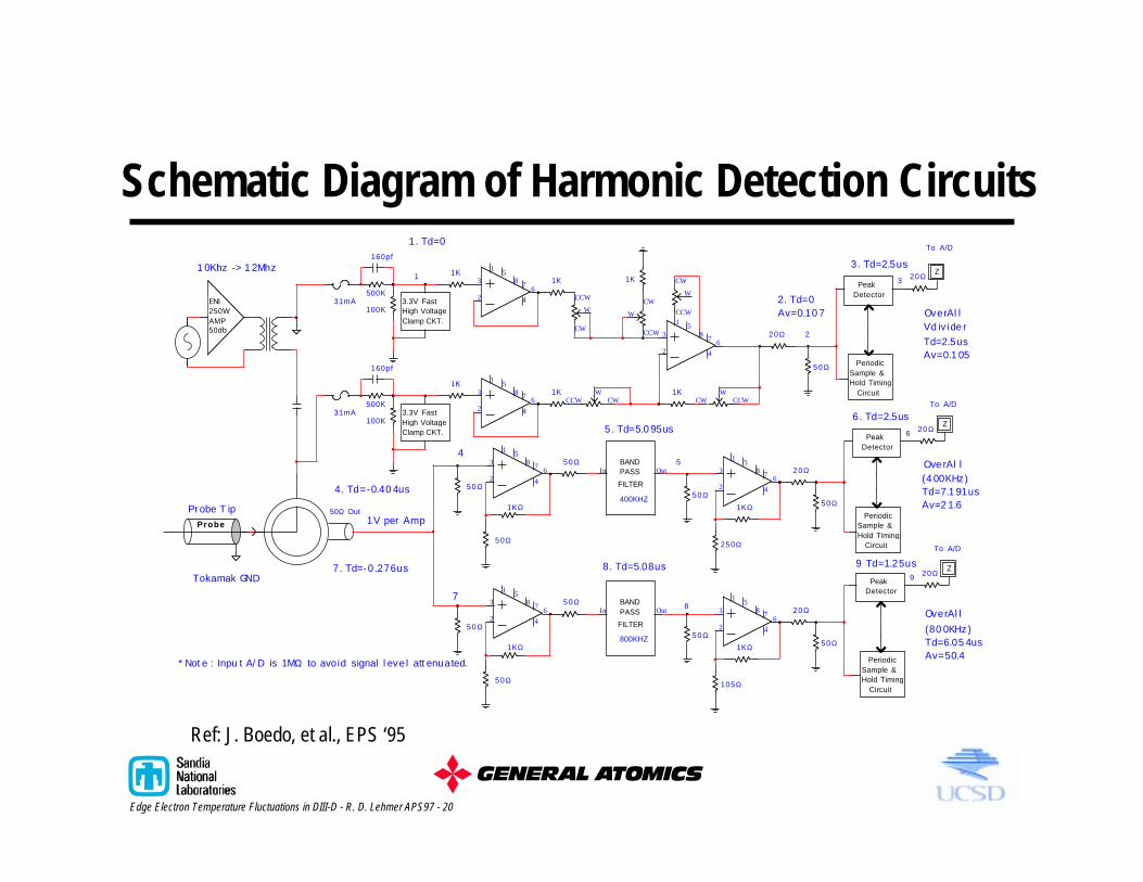
Schematic Diagram of Harmonic Detection Circuits
Ref: J. Boedo, et al., EPS ‘95

QTYUIOPEdge Electron Temperature Fluctuations in DIII-D - R. D. Lehmer APS97 - 21
Ratio of Filter Responses is Linear Over Required Bandwidth, but SNR is High
• Individual Output Amplitudes for Each Filter Begin to Roll-Off above 50kHz, however, Ratio of Amplitudes Remains Approximately Constant.
• We will Test System with this Bandwidth and Proceed to Specify Filters with Higher Bandwidth.
0
0.2
0.4
0.6
0.8
1
1.2
Ratio
: Am
p(1)
/Am
p(2)
0 50 100 150 200 250
Frequency (kHz)
0
0.25
0.5
0.75
1
1.25
Out
put A
mp/
Ref S
igna
l (re
lativ
e)
0 50 100 150 200 250
Frequency (kHz)
1st Harmonic (400kHz)2nd Harmonic (800kHz)

QTYUIOPEdge Electron Temperature Fluctuations in DIII-D - R. D. Lehmer APS97 - 22
Phase Delays in Each Harmonic are less than Characteristic Time of Sample and Hold Circuit
• Phase Delay through Circuits is Constant Up Through Maximum Frequency (200kHz):
8.5µs for 1st Harmonic6.9µs for 2nd Harmonic

QTYUIOPEdge Electron Temperature Fluctuations in DIII-D - R. D. Lehmer APS97 - 23
Harmonic Detection System at TEXTOR Characterized Turbulent and Equilibrium Edge Te
• Good Agreement with Equilibrium Te Profile from Double Probe at Edge; Divergence in SOL Due to Over Drive of Harmonic Circuit (U0/Te >1).
• Normalized RMS Fluctuation Levels (Including Te Fluctuations) Similar to Observations from TEXT and TJ-I.
MachineTEXT [1,3] 0.3-0.5 0.15-0.2 0.2-0.5 0.2 0.1 0.3-0.5TJ-1 [5] 0.3-0.5 0.4-0.5TEXTOR 0.2-0.3 0.2-0.7 0.3-0.7 0.15-0.25 0.2 0.2-0.4
n~
n
SOL
Te~
Te
SOL
V f~
kTe
SOL
n~
n
edge
Te~
Te
edge
V f~
kTe
edge
0
20
40
60
80
Te
(eV
)
45 46 47 48 49 50
Radius (cm)
Te Harmonics
Te Double Probe
Ref: J. Boedo, EPS 1995