FLOW FORMING: A REVIEW OF RESEARCH METHODOLOGIES ...
31
http://www.iaeme.com/IJMET/index.asp 285 [email protected] International Journal of Mechanical Engineering and Technology (IJMET) Volume 7, Issue 5, September–October 2016, pp.285–315, Article ID: IJMET_07_05_29 Available online at http://www.iaeme.com/ijmet/issues.asp?JType=IJMET&VType=7&IType=5 Journal Impact Factor (2016): 9.2286 (Calculated by GISI) www.jifactor.com ISSN Print: 0976-6340 and ISSN Online: 0976-6359 © IAEME Publication FLOW FORMING: A REVIEW OF RESEARCH METHODOLOGIES, PREDICTION MODELS AND THEIR APPLICATIONS Daniele Marini Department of Design, Manufacture and Engineering Management (DMEM), University of Strathclyde, United Kingdom; Technology and Innovation Centre (TIC), University of Strathclyde, United Kingdom. David Cunningham,Paul Xirouchakis and Jonathan R.Corney Department of Design, Manufacture and Engineering Management (DMEM), University of Strathclyde, United Kingdom. ABSTRACT After years of largely academic interest and niche applications, a new generation of high duty CNC machines is enabling the flow forming process find increasing application in aerospace, automotive and defense industries. The versatility of digital control has made it economically viable to deliver weight and cost savings for small to medium batch sizes while simultaneously improving quality and material proprieties. To better understand the capabilities of flow forming this review surveys the reported research over last fifty years and summarizes both theoretical models and experimental investigations. Where possible the contributions of different researchers are described and assessed in terms of the accuracy of their predictive capabilities. In some cases practice has preceded the development of theory for example: the ratio of circumferential to axial contact is widely used as a defect prediction parameter, even if the process’ failure mechanism is still not fully understood. In other areas, such as forming forces and powers, the literature provides a clear rational based on experimentally validated analytical models. In addition to summarizing current knowledge the review also identifies gaps in currently literature where more research is required. For example: the evolution of stress/strain tensors during a flow forming process has not been reported due to the high computational cost and a lack of consensus on the most appropriate finite elements modeling approach to adopt. Similarly while the final microstructure of a formed part is often evaluated models of its development (during the series of plastic deformations created by a flow forming process) have not been reported. Likewise residual stress and final material proprieties, such as corrosion behaviour, have been not studied numerically or experimentally. It is also noted that the impact of tool paths (e.g. their geometry and topology) has not been deeply explored. Lastly the authors note, the surprising observation, that only a few researchers have reported the experimental optimization and characterization of flow forming process parameters using a ‘Design of Experiments’ methodology.
Transcript of FLOW FORMING: A REVIEW OF RESEARCH METHODOLOGIES ...

http://www.iaeme.com/IJMET/index.asp 285 [email protected]
International Journal of Mechanical Engineering and Technology (IJMET) Volume 7, Issue 5, September–October 2016, pp.285–315, Article ID: IJMET_07_05_29
Available online at
http://www.iaeme.com/ijmet/issues.asp?JType=IJMET&VType=7&IType=5
Journal Impact Factor (2016): 9.2286 (Calculated by GISI) www.jifactor.com
ISSN Print: 0976-6340 and ISSN Online: 0976-6359
© IAEME Publication
FLOW FORMING: A REVIEW OF RESEARCH
METHODOLOGIES, PREDICTION MODELS AND
THEIR APPLICATIONS
Daniele Marini
Department of Design, Manufacture and Engineering Management (DMEM), University of Strathclyde,
United Kingdom;
Technology and Innovation Centre (TIC), University of Strathclyde, United Kingdom.
David Cunningham,Paul Xirouchakis and Jonathan R.Corney
Department of Design, Manufacture and Engineering Management (DMEM),
University of Strathclyde, United Kingdom.
ABSTRACT
After years of largely academic interest and niche applications, a new generation of high duty
CNC machines is enabling the flow forming process find increasing application in aerospace,
automotive and defense industries. The versatility of digital control has made it economically
viable to deliver weight and cost savings for small to medium batch sizes while simultaneously
improving quality and material proprieties.
To better understand the capabilities of flow forming this review surveys the reported research
over last fifty years and summarizes both theoretical models and experimental investigations.
Where possible the contributions of different researchers are described and assessed in terms of the
accuracy of their predictive capabilities. In some cases practice has preceded the development of
theory for example: the ratio of circumferential to axial contact is widely used as a defect
prediction parameter, even if the process’ failure mechanism is still not fully understood. In other
areas, such as forming forces and powers, the literature provides a clear rational based on
experimentally validated analytical models.
In addition to summarizing current knowledge the review also identifies gaps in currently
literature where more research is required. For example: the evolution of stress/strain tensors
during a flow forming process has not been reported due to the high computational cost and a lack
of consensus on the most appropriate finite elements modeling approach to adopt. Similarly while
the final microstructure of a formed part is often evaluated models of its development (during the
series of plastic deformations created by a flow forming process) have not been reported. Likewise
residual stress and final material proprieties, such as corrosion behaviour, have been not studied
numerically or experimentally. It is also noted that the impact of tool paths (e.g. their geometry and
topology) has not been deeply explored. Lastly the authors note, the surprising observation, that
only a few researchers have reported the experimental optimization and characterization of flow
forming process parameters using a ‘Design of Experiments’ methodology.

Daniele Marini, David Cunningham, Paul Xirouchakis and Jonathan R. Corney
http://www.iaeme.com/IJMET/index.asp 286 [email protected]
Key words: Flow forming, Review, Spinning, Design of Experiment, Process modeling
Cite this Article: Daniele Marini, David Cunningham, Paul Xirouchakis and Jonathan R.
Corney,Flow Forming: A Review of Research Methodologies, Prediction Models and their
Applications. International Journal of Mechanical Engineering and Technology, 7(5), 2016, pp.
285–315.
http://www.iaeme.com/ijmet/issues.asp?JType=IJMET&VType=7&IType=5
1. INTRODUCTION
The flow forming process manufactures rotational components using deformation forces generated by
rotating rollers that compress and stretch a blank (called a preform) though consecutive stages over a
mandrel. Despite the limited commercial applications of the process a steady stream of research into its
mechanics and characterization has been reported (mainly by German and Japanese researchers) since its
introduction in the 1950s. (Figure 2). Today flow forming is of growing importance because it:
• Produces components with good tolerance control and geometrical accuracy.
• Allows precise control of a component’s wall thicknesses and so enables the manufacture of optimized
designs.
• Supports a large range of workable materials (e.g. Steel, Alloy Steel, Titanium and Titanium Alloy, Brass,
Copper, Aluminium, Nickel, Niobium).
• Improves the mechanical properties of formed materials (through working hardening).
• Generates components with excellent surface roughness (compared with other plastic deformation
processes).
• Increases mechanical properties due to cold working (hardening) effects.
• Results in cost saving due to reduction in finish machining operations.
• Avoid material waste (compared with both classic forging or forming processes and machining).
• Costing savings due to heat treatment reduction.
The economic advantages arise from the processes ability to form material into a complicate shape that
allows the elimination of subsequent manufacturing or finishing steps. Thus a reduction of cost can be
achieved while simultaneously enabling lightweight designs with good mechanical properties.Any
comprehensive literature review for flow-forming, must address both the physical mechanisms underlying
the process and their application in the engineering of manufacturing procedures. To provide a framework
for the review that effectively distinguished between these two interacting streams of work, the
methodology proposed in Music et al.(2010) (for shear forming) has been adopted Figure 1). To identify
where the emphasis of this framework will differ from that proposed for shear forming, reviews such as
Sivanandini et al.(2012) and Wong et al.(2005) have been used to establish the appropriate scope. This
process concluded that in order to apply the framework to flow forming it should be expanded to
incorporate issues of microstructure (whose effect is fundamental to local yielding and deformation) in the
knowledge section, as initialized in Marini et al.(2015). Likewise the ‘applications’ section should be
extended to include the mechanical characteristics of the final product (because flow forming can
frequently enhance these). The following sections populates the Figure 1 framework from left to right with
Sections 2 and 3 presenting ‘knowledge’ (i.e. theory) and Section 4 detailing contributions related to
applications .
The details, within this overall structure, are as follows: the Introduction concludes with three more
sections that cover flow forming’s general features and distinguishes it from, the more common, shear and
spinning processes. Section 2 reviews the research methodologies adopted by flow-forming researchers by
dividing them in experimental and theoretical (i.e. analytical and numerical) with a sub-section dedicated
to ‘Design of Experiments’ (DoE). Section 3 summarizes the outputs available to support the prediction of

Flow Forming: A Review of Research Methodologies, Prediction Models and their Applications
http://www.iaeme.com/IJMET
flow forming issues. Section 4 summarizes the reported applications of developed knowledge in areas
ranging from the achievement of production targets to the process planning of the flow forming process.
Section 5 concludes the review by highlighting current gaps in knowledge and identifying future research
aims.
Figure 1 Review methodology developed from [Music
1.1. Flow Forming Definitions and T
Flow forming plastically deformation a hollow metal blank on a
generated by a number of moving rollers (Figure 3).The blank’s material is constrained to flow in an axial
direction by the movement (i.e. feed) of a number of rollers. Large thickness reductions of over 50% can
be achieved with multiple passes of the rollers (i.e. several repetitions of the forming process) while the
internal diameter remains almost constant.
This distinctive capability of the process is characterized by the reduction ratio (
or
Where, 0t is the initial thickness of the blank and t is the final thickne
Kudo(1979). In later sections of this review the limits
properties or machine power are frequently defined in terms of reduction ratio. For example t
“spinnability” is defined by Kalpakcioglu
This large and controlled change in the thickness of the workpiece is often cited as the crucial
difference between flow forming and conventional spinning (where the thicknes
Flow Forming: A Review of Research Methodologies, Prediction Models and their Applications
IJMET/index.asp 287
flow forming issues. Section 4 summarizes the reported applications of developed knowledge in areas
ranging from the achievement of production targets to the process planning of the flow forming process.
by highlighting current gaps in knowledge and identifying future research
Review methodology developed from [Music et al.(2010)
Flow Forming Definitions and Terminology
Flow forming plastically deformation a hollow metal blank on a rotating mandrel by means of forces
generated by a number of moving rollers (Figure 3).The blank’s material is constrained to flow in an axial
direction by the movement (i.e. feed) of a number of rollers. Large thickness reductions of over 50% can
ved with multiple passes of the rollers (i.e. several repetitions of the forming process) while the
internal diameter remains almost constant.
This distinctive capability of the process is characterized by the reduction ratio (
0
00 =
t
ttR
−
0
00 ln=
t
tR
is the initial thickness of the blank and t is the final thickness of the workpiece
. In later sections of this review the limits of flow forming processes imposed by, say, material
properties or machine power are frequently defined in terms of reduction ratio. For example t
Kalpakcioglu (1961a) as the maximum reduction achievable.
olled change in the thickness of the workpiece is often cited as the crucial
difference between flow forming and conventional spinning (where the thicknes
Flow Forming: A Review of Research Methodologies, Prediction Models and their Applications
flow forming issues. Section 4 summarizes the reported applications of developed knowledge in areas
ranging from the achievement of production targets to the process planning of the flow forming process.
by highlighting current gaps in knowledge and identifying future research
.(2010)
rotating mandrel by means of forces
generated by a number of moving rollers (Figure 3).The blank’s material is constrained to flow in an axial
direction by the movement (i.e. feed) of a number of rollers. Large thickness reductions of over 50% can
ved with multiple passes of the rollers (i.e. several repetitions of the forming process) while the
This distinctive capability of the process is characterized by the reduction ratio ( 0R ) parameter:
(1)
(2)
ss of the workpiece Hayama and
of flow forming processes imposed by, say, material
properties or machine power are frequently defined in terms of reduction ratio. For example tube
as the maximum reduction achievable.
olled change in the thickness of the workpiece is often cited as the crucial
difference between flow forming and conventional spinning (where the thickness remains essentially

Daniele Marini, David
http://www.iaeme.com/IJMET
constant) Wong et al., (2003) The flow forming process has two main variants known as forward and
reverse (or backward) flow forming. In forward flow forming, the blank is located (i.e. clamped) through
the tailstock and mandrel (requiring the blank to have a suitable
Wong et al., (2003). The arrangement constrains the workpiece material to
the roller s axial movement. In other words it is pushed ahead of the rollers as progress down the mandrel.
In backward flow forming, the workpiece is located against the headstock of the mandrel which forces the
material to “flow” in the opposite direction to roller s motion (i.e. squeezed out from under the rollers
themselves). Although this removes the need for the initial bl
al.(1990) observe that it is easier for defects to occur (compared to forward processes). This is because the
large axial deformations (material can be flowed along the length the mandrel) results in residual stress
can cause distortions and local weak
in a loss of accuracy in the axial direction
Figure 2
Flow forming, shear forming and conventional spinning have several common traits that can make it
difficult for new comers to clearly distinguish between different members of the family of rotational
forming processes. As explained in Runge
production of rotating, symmetrical, hollow components. Spinning is generally defined by workpiece
rotation through a mandrel where the component is clamped usually by tailstocks and is deformed into the
required shape by spinning tools.
The essential difference between flow forming and spinning is that, metal spinning utilizes a relatively
thinner piece of starting material than flow forming and produces the shape of the finished part from a
starting blank whose diameter is bigger than the largest diameter of the finished part. This is similar to
deep drawing, in which no reduction of the wall thickness occurs. Flow forming, on the other hand, is
based upon an precise, pre-determined reduction of the thickness of the starti
reduction Sivanandini et al.(2012).
A form of spinning that both forms sheets on to a mandrel and creates changes in material thickness is
known as shear forming. Essentially flow forming and shear forming vary in the degree of the de
mechanisms employed (e.g. reduction ratio) and the geometry of the billet (i.e. shee
flow). Gur and Tirosh (1982) differentiate between these two processes by describing flow forming as
being a combination of extrusion and
shear forming, which define the angle of available deformation of the piece through the mandrel
Daniele Marini, David Cunningham, Paul Xirouchakis and Jonathan R. Corney
IJMET/index.asp 288
The flow forming process has two main variants known as forward and
reverse (or backward) flow forming. In forward flow forming, the blank is located (i.e. clamped) through
the tailstock and mandrel (requiring the blank to have a suitable ‘flange’ geometry
The arrangement constrains the workpiece material to “flow
the roller s axial movement. In other words it is pushed ahead of the rollers as progress down the mandrel.
forming, the workpiece is located against the headstock of the mandrel which forces the
material to “flow” in the opposite direction to roller s motion (i.e. squeezed out from under the rollers
themselves). Although this removes the need for the initial blank to have a locating flange Singhal et
al.(1990) observe that it is easier for defects to occur (compared to forward processes). This is because the
large axial deformations (material can be flowed along the length the mandrel) results in residual stress
can cause distortions and local weak-points. Consequently backward flow forming is also more susceptible
in a loss of accuracy in the axial direction (Xu et al., 2001; Runge 1994).
Figure 2 Timeline of articles about flow forming process.
ing, shear forming and conventional spinning have several common traits that can make it
difficult for new comers to clearly distinguish between different members of the family of rotational
ing processes. As explained in Runge (1994), the term ‘spinning’ refers to all process for the
production of rotating, symmetrical, hollow components. Spinning is generally defined by workpiece
rotation through a mandrel where the component is clamped usually by tailstocks and is deformed into the
The essential difference between flow forming and spinning is that, metal spinning utilizes a relatively
thinner piece of starting material than flow forming and produces the shape of the finished part from a
s bigger than the largest diameter of the finished part. This is similar to
deep drawing, in which no reduction of the wall thickness occurs. Flow forming, on the other hand, is
determined reduction of the thickness of the starti
.
A form of spinning that both forms sheets on to a mandrel and creates changes in material thickness is
known as shear forming. Essentially flow forming and shear forming vary in the degree of the de
mechanisms employed (e.g. reduction ratio) and the geometry of the billet (i.e. shee
differentiate between these two processes by describing flow forming as
trusion and rolling processes. Kalpakcioglu (1961b)
shear forming, which define the angle of available deformation of the piece through the mandrel
Cunningham, Paul Xirouchakis and Jonathan R. Corney
The flow forming process has two main variants known as forward and
reverse (or backward) flow forming. In forward flow forming, the blank is located (i.e. clamped) through
geometry to enable this fixture)
flow” in the same direction as
the roller s axial movement. In other words it is pushed ahead of the rollers as progress down the mandrel.
forming, the workpiece is located against the headstock of the mandrel which forces the
material to “flow” in the opposite direction to roller s motion (i.e. squeezed out from under the rollers
ank to have a locating flange Singhal et
al.(1990) observe that it is easier for defects to occur (compared to forward processes). This is because the
large axial deformations (material can be flowed along the length the mandrel) results in residual stress that
points. Consequently backward flow forming is also more susceptible
Timeline of articles about flow forming process.
ing, shear forming and conventional spinning have several common traits that can make it
difficult for new comers to clearly distinguish between different members of the family of rotational
refers to all process for the
production of rotating, symmetrical, hollow components. Spinning is generally defined by workpiece
rotation through a mandrel where the component is clamped usually by tailstocks and is deformed into the
The essential difference between flow forming and spinning is that, metal spinning utilizes a relatively
thinner piece of starting material than flow forming and produces the shape of the finished part from a
s bigger than the largest diameter of the finished part. This is similar to
deep drawing, in which no reduction of the wall thickness occurs. Flow forming, on the other hand, is
determined reduction of the thickness of the starting blank, or preform.
A form of spinning that both forms sheets on to a mandrel and creates changes in material thickness is
known as shear forming. Essentially flow forming and shear forming vary in the degree of the deformation
mechanisms employed (e.g. reduction ratio) and the geometry of the billet (i.e. sheet for shear or tube for
differentiate between these two processes by describing flow forming as
) developed a ‘sine law’ for
shear forming, which define the angle of available deformation of the piece through the mandrel

Flow Forming: A Review of Research Methodologies, Prediction Models and their Applications
http://www.iaeme.com/IJMET/index.asp 289 [email protected]
inclination without defects. This determines the spinnability of the metal undergoing these working
conditions. With this hypothesis, Kalpakcioglu (1961a) defines the metal flow conditions for shear forming
and conclude that it is distinctly different from the flow forming process. As in Gur and Tirosh (1982),
Kalpakcioglu (1964) defines the deformation mode of flow forming as being similar to extrusion.
These observations suggest that although similar, shear forming and flow forming are based on
different deformation mechanism and should be treated separately Music et al.(2010). It is also interesting
to note that considerable effort was expended by researchers in the investigation of shear spinning of cones
during early 60s, which achieved both practical and theoretical success. However as Nagarajan et al.(1981)
points out, these models are not able to predict flow forming process behavior correctly.
Given the similarities, and difference, of the various rotational forming processes it is not surprising
that there have been a number of proposals for criteria to produce an unambiguous classification.
The only standard classification of spinning processes is the DIN 8582 standard which classifies
processes by means of the stresses generated during spinning operation. Using this criterion DIN 8584
classifies conventional spinning as processes where plastic deformations are caused by application of tri-
axial compressive and tensile stresses. Similarly flow and shear forming are defined (DIN 8583) as
processes that applies only compressive stresses. Using this classification DIN 8583 makes no distinction
between flow and shear forming. However is clear that while similar in the deformation force applied, flow
and shear forming differ in the nature of preforms and mandrels used.
But the DIN standard does not represent a consensus view, Lange(1985), for example, groups flow
forming and conventional forming with other sheet forming processes (such as deep drawing), and
classifies them as tensile-compressive. Shear forming process are grouped with bulk-forming processes
such as rolling, due to the compressive stresses applied to the workpiece. Similarly Kalpakjian and
Schimd(2009) develops a wide classification of these manufacturing processes and divide them in to bulk
and sheet forming, placing all the spinning processes in the latter. Slightly different is the definition of
Music et al.(2010). They associate metal spinning with a group of forming processes, where the common
mechanism is a plastic deformation on mandrel through single or multiple rollers in one or more stages.
In 1989, Wang, Z.R., Lu (1989) proposed a standard nomenclature for all spinning process, but as
Music et al.(2010) pointed out in 2010, it has not been widely adopted in industrial or research
environment.
In summary there is no universally accepted definition, or taxonomy, for rotational manufacturing
processes. Manufacturer and researcher use different terminology for similar equipment and working
technique, especially for the ones which involve reduction of thickness. For example the process of tube
spinning, flow forming, shear forming and power spinning are all simply classified as tube forming
process. Table 1 summarizes flow forming terminology and nomenclature found in the literature.
Table 1 Flow forming terminology and nomenclature
Term Alternatives Description
Conventional Spinning Multi-pass spinning, deep-
drawing spinning, spinning,
simple spinning (spinning
in a single pass)
Spinning process where a sheet blank is formed into
a desired axisymmetric shape without a change in
the wall thickness and with a deliberate reduction in
diameter either over the whole length or in specific
areas.
Shear spinning Shear forming, flow
forming, shear/flow turning,
power spinning,
hydrodynamic spinning
Spinning process where a sheet blank is formed by a
roller into an axisymmetric part with a desired shape
and thickness distribution. The thickness is
deliberately reduced to obtain a desired distribution
while the diameter of the part remains constant.

Daniele Marini, David Cunningham, Paul Xirouchakis and Jonathan R. Corney
http://www.iaeme.com/IJMET/index.asp 290 [email protected]
Term Alternatives Description
Flow Forming Flow turning, Tube
spinning
Spinning process where a blank is formed into a
desired axisymmetric shape with possibility of
changing in wall thickness and with a constant or
variable reduction in diameter in whole length or in
specific areas.
Roller(s) - Rigid roller that forms the sheet over a mandrel.
Tailstock - Circular disk clamping the sheet to the mandrel.
May be flat or curved to fit over the mandrel and
further support the sheet while it is being formed.
Preform Blank, cup, disk Initial workpiece with different possible shapes,
dependent on the final required shape of product.
Initial thickness ( 0t ) - Original thickness of the part.
Final thickness ( t ) - Final thickness or thicknesses if variable along the
component.
Mandrel Chuck Rigid axisymmetric tool with the profile of the final
component. Supports the workpiece during
deformation.
Roller feed rate Feed rate Linear speed of the rollers in axial direction (mm/s).
Mandrel speed Rotational Speed Rotational speed of the mandrel (rpm).
Feed ratio Feed per rotation, feed per
revolution
Stoke of the roller for every rotation (mm/rev).
Tangential force - Three mutually perpendicular components of the
Axial force - roller force.
Radial force -
Roller nose radius Nose radius Blending radius between the two flat surfaces on the
outer surface of the roller.
Roller attack angle Attack angle, leading
angle, approach angle
Angle lying between mandrel axis and inclined
surfaces of the roller.
Roller diameter - Roller main dimension (mm).
Reduction ratio ( 0R ) Degree of thinning,
thickness reduction ratio,
spinning ration, forming
ratio, maximum reduction
Proportionality between initial thickness and final
thickness.

Flow Forming: A Review of Research Methodologies, Prediction Models and their Applications
http://www.iaeme.com/IJMET
Term
Thickness reduction Diameter reduction, depth
of cut
Limit degree of thinning Limit thickness reduction,
spinnability, critical
reduction ratio
Circumferential Flow ( S ) -
Axial Flow ( L ) -
Figure 3 Flow forming param
2. RESEARCH METHODOLOGI
This section reviews the experimental and analytical methodologies adopted by flow forming researchers.
Some conventional spinning articles are presented when their findings, or theories, have also been shown
to be valid for flow forming.
2.1. Experimental Methodologies
In flow forming, empirical studies have been used to seek to correlations between inputs (e.g. the
workpiece material’s properties and process parameters such as the radial, tangential and axial forces on
the rollers) and outputs (e.g. surf
notable example of this approach are
in to backward and forward tube
reduction ratios and parameters setting (feed rate and rollers angle) on mild steel. First, they evaluate the
impact of process variables on the product s dimensional accuracy. They explicitly distinguish between
Flow Forming: A Review of Research Methodologies, Prediction Models and their Applications
IJMET/index.asp 291
Alternatives Description
Diameter reduction, depth
of cut
Reduction in thickness and diameter
rollers
Limit thickness reduction,
spinnability, critical
reduction ratio
Limit reduction ratio before failure occurring.
Length of circumferential contact between
workpiece and roller, proportional to the material
beneath the roller flowing in a circumferential
direction.
Length of axial contact between workpiece and
roller, proportional to the material beneath the roller
flowing in an axial direction.
Flow forming parameters and geometry description Chang
RESEARCH METHODOLOGIES
This section reviews the experimental and analytical methodologies adopted by flow forming researchers.
Some conventional spinning articles are presented when their findings, or theories, have also been shown
l Methodologies
In flow forming, empirical studies have been used to seek to correlations between inputs (e.g. the
s properties and process parameters such as the radial, tangential and axial forces on
the rollers) and outputs (e.g. surface roughness, mechanical properties or dimensional accuracy).
oach are Hayama and Kudo(1979b) who report an experimental investigation
in to backward and forward tube-spinning (effectively flow forming with two rollers) throu
reduction ratios and parameters setting (feed rate and rollers angle) on mild steel. First, they evaluate the
impact of process variables on the product s dimensional accuracy. They explicitly distinguish between
Flow Forming: A Review of Research Methodologies, Prediction Models and their Applications
Description
Reduction in thickness and diameter imposed by the
Limit reduction ratio before failure occurring.
Length of circumferential contact between
workpiece and roller, proportional to the material
beneath the roller flowing in a circumferential
Length of axial contact between workpiece and
roller, proportional to the material beneath the roller
flowing in an axial direction.
Chang et al.(1998)
This section reviews the experimental and analytical methodologies adopted by flow forming researchers.
Some conventional spinning articles are presented when their findings, or theories, have also been shown
In flow forming, empirical studies have been used to seek to correlations between inputs (e.g. the
s properties and process parameters such as the radial, tangential and axial forces on
ace roughness, mechanical properties or dimensional accuracy). A
who report an experimental investigation
spinning (effectively flow forming with two rollers) through different
reduction ratios and parameters setting (feed rate and rollers angle) on mild steel. First, they evaluate the
impact of process variables on the product s dimensional accuracy. They explicitly distinguish between

Daniele Marini, David Cunningham, Paul Xirouchakis and Jonathan R. Corney
http://www.iaeme.com/IJMET/index.asp 292 [email protected]
different material flow conditions using the concept of a plastic wave (created in the upper zone of contact
between the roller and the workpiece) of material displaced along the workpiece. A coefficient that defines
the size of the plastic wave is defined and used to evaluate the stability of the process. Not surprisingly
larger wave sizes are associated with an unstable process.
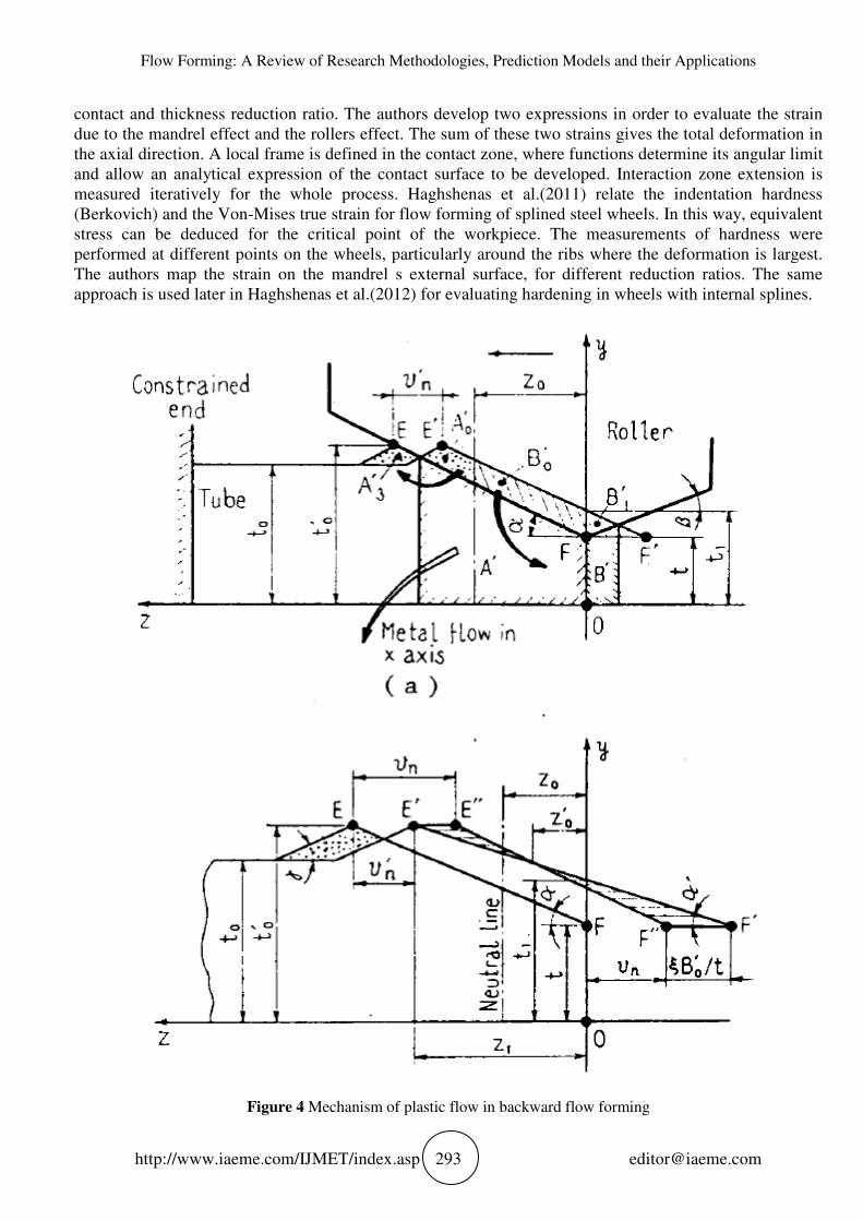
The experimental validation of an analytical model of flow forming is reported in Hayama and
Kudo(1979a) that represents the volume of material that flows in axial direction, (which is a fraction of the
volume of material involved in the deformation process). These parameters give a numerical explanation
of the physical phenomena of deformation. The results confirm the influence of thickness reduction ratio,
feed rate and roller geometry on process stability and accuracy. Figure 4 shows the reference system used
and the material flow model for backward flow forming.
Experimental work by [Jahazi and Ebrahimi(2000) also demonstrates that the axial flow must
overcome the circumferential flow in order to avoid friction phenomena and avoid defects in the final
product (e.g. waves on the external surface and thickness inhomogeneity).
Singhal et al.(1987) test these theories on hardest and low deformable materials by conducting
experiments on various alloys such as pure Titanium, Titanium alloys (Incoloy 825), Ni-Cr steel (Inconel
600) and stainless steel (AISI-304). Different reduction ratios were tested to evaluate the final material
proprieties and dimensional accuracy, as well as a microscopic investigation for evaluating the final
product hardness.
Chang et al.(1998) also investigated the forming limits of Aluminium alloys for forward and backward
flow forming, adopting different process parameters and rollers configurations. The tested materials are
two different alloys (2024 and 7075) and two different heat treatments (full-annealed and solution-treated),
giving a total of four combinations. Micro-spinnability and macro-spinnability are evaluated for these four
combinations of materials and heat treatments. The latter is evaluated by varying the thickness reduction
until failure (destructive testing) or until reaching the desired reduction ratio (non-destructive methods).
Micro-spinnability is evaluated with non-destructive methods such as microscopic techniques (TEM, SEM,
OM) and Vickers hardness measurement for detecting the presence of microcracks and microvoids on the
surface.
Jahazi and Ebrahimi(2000) investigates the effect of flow forming on steel using Vickers and Rockwell
hardness tests. By assessing yield strength and final true strain of the material, they are able to measure the
fracture resilience of the material. The trials are conducted for different rollers geometry and reduction ratios.
They also map the relationship between axial contact and circumferential contact, which are evaluated using
the S/L (equation 7 to 12) methodology Gur and Tirosh (1982). Rajan and Narasimhan(2001) investigate the
occurrence of defects in flow forming process for steel tubes. The authors use a sequence of non-destructive
and destructive investigations that consist of a proof pressure test followed by a burst pressure test, in order
to evaluate the final product proprieties. Rajan et al.(2002a) perform different tests on flow formed pressure
vessels in AISI 4130 steel in order to evaluate the effect of the heat treatments (annealing, normalizing,
quenching and tempering). Rajan et al.(2002b) also investigate on the production of flow formed pressure
vessels, applying high pressure until material failure (Svensonn model). The microstructure is investigated in
order to detect the grade of grain elongation, in comparison with thickness reduction. The authors described a
number of distinct phases of the forming process using a flowchart and apply analytical method to determine
the preform dimensions and the expected ultimate strength.
Groche and Fritsche(2006) apply flow forming to the production of a wheel with internal gears teeth.
Their description of the development of three dedicated mandrels and rollers configuration is a significant
contribution. Gupta et al.(2007) investigate flow formed crack propagation mechanism for Niobium alloys.
Material proprieties are evaluated through SEM investigation and hardness tests with visual inspection to
locate defects. Davidson et al.(2008) investigates the causes of roundness errors and variability in other
measures of flow forming quality.
Roy et al.(2009) test surface micro hardness (Berkovic) of a workpiece to map true stress and strain
resulting from forward flow forming operation. Evolution of strain is characterized by roller/mandrel
Flow Forming: A Review of Research Methodologies, Prediction Models and their Applications
http://www.iaeme.com/IJMET
contact and thickness reduction ratio. The authors develop two expressions in
due to the mandrel effect and the rollers effect. The sum of these two strains gives the total deformation in
the axial direction. A local frame is defined in the contact zone, where functions determine its angular limit
and allow an analytical expression of the contact surface to be developed. Interaction zone extension is
measured iteratively for the whole process.
(Berkovich) and the Von-Mises true strain for flow formi
stress can be deduced for the critical point of the workpiece. The measurements of hardness were
performed at different points on the wheels, particularly around the ribs where the deformation is largest.
The authors map the strain on the mandrel s external surface, for different reduction ratios. The
approach is used later in Haghshenas
Figure 4 Mechanism of plastic flow in backward flow forming
Flow Forming: A Review of Research Methodologies, Prediction Models and their Applications
IJMET/index.asp 293
contact and thickness reduction ratio. The authors develop two expressions in
due to the mandrel effect and the rollers effect. The sum of these two strains gives the total deformation in
the axial direction. A local frame is defined in the contact zone, where functions determine its angular limit
llow an analytical expression of the contact surface to be developed. Interaction zone extension is
atively for the whole process. Haghshenas et al.(2011) relate the indentation hardness
Mises true strain for flow forming of splined steel wheels. In this way, equivalent
stress can be deduced for the critical point of the workpiece. The measurements of hardness were
performed at different points on the wheels, particularly around the ribs where the deformation is largest.
The authors map the strain on the mandrel s external surface, for different reduction ratios. The
Haghshenas et al.(2012) for evaluating hardening in wheels with internal splines.
Mechanism of plastic flow in backward flow forming
Flow Forming: A Review of Research Methodologies, Prediction Models and their Applications
contact and thickness reduction ratio. The authors develop two expressions in order to evaluate the strain
due to the mandrel effect and the rollers effect. The sum of these two strains gives the total deformation in
the axial direction. A local frame is defined in the contact zone, where functions determine its angular limit
llow an analytical expression of the contact surface to be developed. Interaction zone extension is
.(2011) relate the indentation hardness
ng of splined steel wheels. In this way, equivalent
stress can be deduced for the critical point of the workpiece. The measurements of hardness were
performed at different points on the wheels, particularly around the ribs where the deformation is largest.
The authors map the strain on the mandrel s external surface, for different reduction ratios. The same
for evaluating hardening in wheels with internal splines.
Mechanism of plastic flow in backward flow forming

Daniele Marini, David Cunningham, Paul Xirouchakis and Jonathan R. Corney
http://www.iaeme.com/IJMET/index.asp 294 [email protected]
Podder et al.(2012) discuss the influence of preform heat treatment on the reduction ratio and its
influence on final strength for backward flow forming. To do this they map the true stress and strain for
different heat treatments (e.g. spheroidizing, hardening and tempering, annealing). Notarigiacomo et
al.(2009) investigate the influence of process parameters on fatigue behavior of flow formed wheels for
automotive industry. The authors develop an experimental correlation between strength and surface
proprieties of wheels. They develop and validate a FEM fatigue model which is able to predict the
increasing fatigue life associated with thickness variation.
2.1.1. Design of Experiments (DoE)
Design of experiments (DOE) is a methodology for designing programs of experiments to determine the
relationship between factors affecting processes and their output. By identifying cause-and-effect
relationships process inputs can be managed to optimize outputs.
Davidson et al.(2008) use Taguchi Orthogonal Arrays (OAs) in order to evaluate the critical factors and
their influence on the mean value of reduction ratio for an aluminum alloy. The authors also use another
statistical method, called analysis of variance (ANOVA), with the aim of quantifying the relative influence
of each parameter. Using this, a general optimization based on the selection of parameter levels is
developed. In another investigation on aluminum alloys, Nahrekhalaji(2010) use classic DoE with
fractional factorial design in order to characterize the flow formed diameter thorough a polynomial
regression equation. Although the number of variables is probably too high (related to the number of trails)
to give a robust statistical significance to the results (i.e. the error’s degree of freedom in ANOVA analysis
would be too low).
Srinivasulu et al.(2012a) develop a characterization of the process through the use of a particular
classic DoE design (Box-Behnken), which is related with RSM (response surface methodology) evaluation
of the results. Their ANOVA takes into consideration the importance of the degree of freedom. The RSM
is able to predict the internal diameter in the selected range of variables with good approximation (i.e. the
error is less than 0.08%). Jalali Aghchai et al.(2012) use fractional factorial DoE and graphical methods
(i.e. RSM) in order to characterize the variables of their model for steel. They report that Analysis of
Variance determines the reduction ratio has more influence on process than roller geometry and axial
speed. The authors propose and optimized set of the variables built by simulation trials for validation.
Wang et al. use only an interaction plot and analysis of means without producing optimization of output.
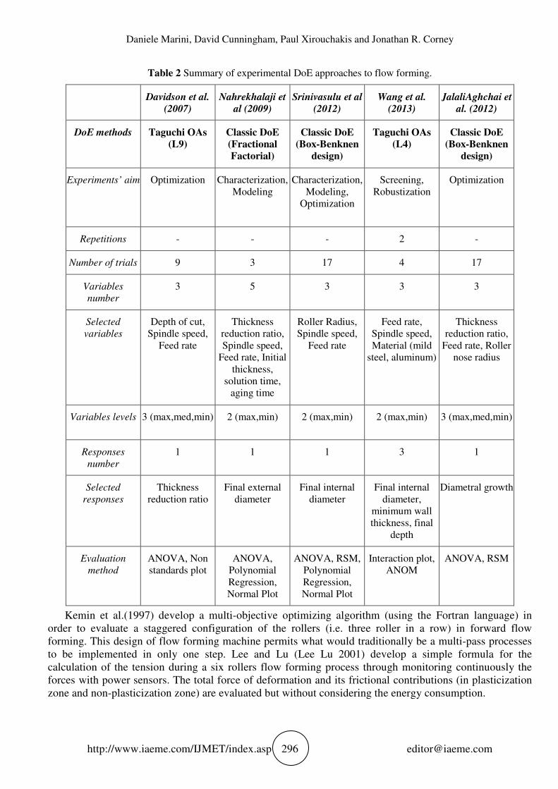
Table 2 summarizes characteristics of the reported application of DoE to investigation of flow forming
process.
2.2. Theoretical Methodologies
Theoretical methodologies are able to investigate the tension and displacement states and their evolution in
the deformed blank during the flow forming process. A combination of this knowledge with failure, or
deformation, models and criteria can predict the failure (i.e. damage accumulation) and final characteristics
of the worked piece.
2.2.1. Analytical
The main focus of analytical research is to develop a model of the flow of the metal during the flow
forming process. This would provide the means to quantify the working energies and the forces required to
form a specific geometry from a given billet. This can also give general feasibility boundaries for the
process (e.g. the maximum reduction ratio achievable in one pass for a certain kind of process and
metals). All the models start with the assumption of conservation of volume and consequently evaluate its
distribution between axial growing and radial reduction.
Mohan and Misra (1970), use a grid-lines model in order to evaluate the tri-axial state of strain during
flow forming process. Their energy based calculations of plastic work are grounded in an assumption of
linear deformation. Calculations of the displacement and knowledge of the material proprieties make it

Flow Forming: A Review of Research Methodologies, Prediction Models and their Applications
http://www.iaeme.com/IJMET/index.asp 295 [email protected]
possible to evaluate the strain tensor. The main problem of this theory is the need for point-to-point
calculation of all displacements values during the process. Using their own metal flow schematization and
volume exchanging parameters, Hayama and Kudo (1979a) develop an energy model in order to predict
the working forces and their relation with the reduction ratio. They divide the energy exchange in the
process into four main parts: plastic deformation energy (under the roller), velocity discontinuity energy
(due to the metal flow velocity discontinuities in the various worked zone), frictional energy (contacts
between mandrel/piece and piece/rollers)and blocking energy (mandrel constrains). They are able to make
a unified theory for backward and forward spinning by identifying the position of the neutral line of plastic
flow. This zone identifies the volume of material that passes from the front of the roller to the growing
zone of the worked piece. For the backward process, this zone is located at a certain distance from the
roller on the feed axis. In contrast, the forward has this point exactly under the contact point between
roller/piece. Singhal et al.(1990) simplify Hayama and Kudo (1979a) approach for stainless steels,
excluding diametral growth, which is negligible for hard materials. They evaluate power absorbance by
friction and velocity, and make the conclusion that the first (i.e. friction) has no influence. Jolly and Bedi
(2010) apply same model but with a different reference system. They use a polar coordinates system and a
circumferential force. The authors define the contact zone between rotating tools and workpiece as a
circular sector of the roller (14°), which is consider infinitely rigid. Regarding aluminum alloys, another
application of the Hayama s model is described by Molladavoudi and Djavanroodi (2010), including
diametral growth and plasticity parameters. The authors include microstructural analysis and defects
correlation with process parameters, and reach conclusions similar to other experimental evaluations.
Gur and Tirosh (1982) use an upper-bound method for analysing the contact between roller and
workpiece during flow forming process. Material may flow beneath the roller in an axial direction (L) or
circumferential direction (S). If the length of circumferential contact is much longer than the axial contact
length, then the axial plastic flow dominates the circumferential one. Axial flow must overcome the
circumferential in order to avoid huge friction phenomena and avoid defects in the final product (waves on
the external surface and thickness inhomogeneity). The authors develop simple formulas for S and L. In
this way, it is possible to evaluate S/L (equation 7 to 12:) ratio for establishing dominant flow and defect
insurgence. This methodology has been tested and validated for different conditions and materials by
several papers, through experimental and numerical method Jahazi and Ebrahimi (2000), Rajan and
Narasimhan (2001), Roy et al.(2010) Parsa et al.(2008) Jalali Aghchai et al.(2012), Podder et al.(2012)
Podder. Mathematical expressions of circumferential and axial contact are described in the ppendix.
Roy et al.(2010) extend this work in order to obtain a detailed analytical expression of contact zone.
Division of contact in various sectors allows the authors to identify different contribution of process
parameters in the contact surface area. Experimental results confirm the validity of the model and the
approximation obtained by the S/L ratio. The mathematical model has a complex geometrical approach
even if it does not include a correlation between the material and superficial proprieties.
Park et al.(1997) develop an upper-bound method built in comparison with traditional tubes ironing.
Stream functions are developed in order to evaluate the changing speed in the material during backward
and forward flow forming processes using the same approach. Plastic stream stress and working forces are
calculated taking into consideration three different type of velocity fields in the material (one trapezoidal
and two spherical).
Nagarajan et al.(1981) adopt previous models for shear forming and spinning (such as Mohan and
Misra Mohan and Misra (1970) and report a systematic evaluation of them through experiments and
empirical data to establish the effectiveness of the models. Rotarescu (1995) applies a similar approach for
the flow forming of tubes using spherical tools. Obviously, the author develops a different contact zone
model in order to evaluate the multi-balls deformation mechanism.
Daniele Marini, David Cunningham, Paul Xirouchakis and Jonathan R. Corney
http://www.iaeme.com/IJMET/index.asp 296 [email protected]
Table 2 Summary of experimental DoE approaches to flow forming.
Davidson et al.
(2007)
Nahrekhalaji et
al (2009)
Srinivasulu et al
(2012)
Wang et al.
(2013)
JalaliAghchai et
al. (2012)
DoE methods Taguchi OAs
(L9)
Classic DoE
(Fractional
Factorial)
Classic DoE
(Box-Benknen
design)
Taguchi OAs
(L4)
Classic DoE
(Box-Benknen
design)
Experiments’ aim Optimization Characterization,
Modeling
Characterization,
Modeling,
Optimization
Screening,
Robustization
Optimization
Repetitions - - - 2 -
Number of trials 9 3 17 4 17
Variables
number
3 5 3 3 3
Selected
variables
Depth of cut,
Spindle speed,
Feed rate
Thickness
reduction ratio,
Spindle speed,
Feed rate, Initial
thickness,
solution time,
aging time
Roller Radius,
Spindle speed,
Feed rate
Feed rate,
Spindle speed,
Material (mild
steel, aluminum)
Thickness
reduction ratio,
Feed rate, Roller
nose radius
Variables levels 3 (max,med,min) 2 (max,min) 2 (max,min) 2 (max,min) 3 (max,med,min)
Responses
number
1 1 1 3 1
Selected
responses
Thickness
reduction ratio
Final external
diameter
Final internal
diameter
Final internal
diameter,
minimum wall
thickness, final
depth
Diametral growth
Evaluation
method
ANOVA, Non
standards plot
ANOVA,
Polynomial
Regression,
Normal Plot
ANOVA, RSM,
Polynomial
Regression,
Normal Plot
Interaction plot,
ANOM
ANOVA, RSM
Kemin et al.(1997) develop a multi-objective optimizing algorithm (using the Fortran language) in
order to evaluate a staggered configuration of the rollers (i.e. three roller in a row) in forward flow
forming. This design of flow forming machine permits what would traditionally be a multi-pass processes
to be implemented in only one step. Lee and Lu (Lee Lu 2001) develop a simple formula for the
calculation of the tension during a six rollers flow forming process through monitoring continuously the
forces with power sensors. The total force of deformation and its frictional contributions (in plasticization
zone and non-plasticization zone) are evaluated but without considering the energy consumption.

Flow Forming: A Review of Research Methodologies, Prediction Models and their Applications
http://www.iaeme.com/IJMET/index.asp 297 [email protected]
2.2.2. Numerical
Finite Element Models (FEM) allow aspects of the flow forming process to be evaluated that are
impossible to assess analytically (e.g. roller deformation). Numerical simulation avoids the expense of
experiments and allows precise understandings of process trade-offs to be developed. However the implicit
necessity of 3-dimensional modeling and complexity of contact surfaces create difficulties in this kind of
approach. Despite this, eleven papers have reported numerical models for flow forming. Three papers use
an implicit approach Xu et al.(2001), Kemin et al.(1997b,c) meanwhile six use an explicit approach Wong
et al.(2005), Lexian and Dariani(2008), Parsa et al.(2008), Jalali Aghchai et al.(2012), Li et al.(1998),
Mohebbi and Akbarzadeh(2010)Wong et al.(2004compare both approaches. Only two papers Xu et
al.(2001), Li et al.(1998) Li, Hao, Lu and Xue model numerically the friction between roller and
workpiece, (while other authors neglects friction contributes to displacement). Most use commercial
software (e.g. ABAQUS) which has been modified to incorporate appropriate solution codes.
Wong et al.(2005) combine two different roller path and different rollers geometry (flat and with nose)
in order to evaluate their effect. The two different types of roller identified are radial and axial. These are
determined by the approach direction. Both radial and axial path are possible depending on the approach
direction taken towards the blank. In a radial approach the axis is perpendicular to the spindle axis, in an
axial paths it is parallel. The influence of these two methods on the final proprieties, working force and
defects are combined with influence of roller geometry.
Lexian and Dariani (2008) develop a non-linear model that simulates the contact surface between roller
and workpiece, excluding the friction among the parts. Surfaces are modeled with 3D-shell elements.
Kemin et al.(1997b) use 3D-bricks element in order to evaluate working forces in a three, staggered, rollers
deformation process. In contrast to all other researchers, they use the ADINA FEA software. This attempt
extends the authors previous work on 2-dimensional modeling of the flow forming process Kemin et
al.(1997c) in order to evaluate the linearity/non-linearity of the contacts in a two roller flow forming
system. The symmetry of the contact point makes it possible to model the rotating surface during the
process.
Li et al.(1998) developed a rotational transformation matrix in order to reformulate the simple hinges
model on the contact surface in polar coordinates. This coordinates transformation is applicable in both the
flow forming variants, if 3D elements are applied and allow easy definition of the constraints associated
with mandrel and rollers.
In Xu et al.(2001) the application of the differential equation to the numerical model follow a particular
methodology (Markov). The stress and strain states are evaluated and associated to different states of
tension around the contact zone for reverse and forward flow forming. Although the model is complex, the
results agree with Hayama and Kudo (1979a)’s approach (giving further validity to this model). Explicit
and implicit solutions for FEA are proposed by Wong et al. (2004) for the flow forming of lead. The
results of the analysis suggest that the implicit method gives the best correlation with the experimental
results.
However, Parsa et al. (2008) report an explicit solution, justifying this choice with the possibility of
maintain the interaction between nodes and the consequent transfer of forces with better coherency.
Mohebbi and Akbarzadeh (2010) also use an implicit solver for simulating the flow forming process. In
order to evaluate the local deformation, pins are mounted on the worjpiece to allow experimental
validation of the model. Jalali Aghchai et al.(2012) use DoE for evaluating most important factors
effecting diametral growth. The S/L (equation 7 to 12) ratio is used to validate their model s results. This is
a good example of use of a DoE methodology to structure the analysis produced by FEM investigations. In
this way only statistical relevant parameters for the selected responses are evaluated during numerical
modeling.
The above suggest that implicit code is more directly related to nature of the problem than explicit one.
The difficulty of converging solutions for the highly nonlinear process and the high computational cost of
implicit approaches have pushed researchers to select explicit methods. Overall the explicit approach seems

Daniele Marini, David Cunningham, Paul Xirouchakis and Jonathan R. Corney
http://www.iaeme.com/IJMET/index.asp 298 [email protected]
to be the best alternative because of its robustness, computational efficiency, and its ability to produce a
largely quasi-static response. Explicit code is also conditionally stable although it is affected by challenges
inherent in implementing sufficient time steps due to the process long computational cycle time. One
proposal for overcoming this computational problem is to reduce the number of increments by increasing
material density or loading speed, as expressed in Wong et al.(2004). Although, this approach may increase
computational speed effects, it will decrease solution accuracy (i.e. impacting on inertial effects).
3. PREDICTION MODELS: THE MECHANICS OF FLOW FORMING
An overview of theoretical and experimental approaches is given in this section where the flow forming
mechanism is analyzed through the models used by various authors. Papers about conventional spinning,
judged relevant to flow forming applications, are also presented in this chapter.
3.1. Prediction of Product Final Geometry
Relating the final product geometry to specific process parameters is one of the main aims of researchers
working flow forming. However the task is far from simple; For example although the final diameter is
imposed by roller distance several effects, such as springback, material proprieties and tension state also
influence the final shape of the flow formed product. Accuracy of product diameter and dimensional
tolerance are related to both process parameters and machine configuration, so researchers have
investigated how these interact to determine the final geometry. The diametral growth of formed parts is
studied analytically and numerically, but experimental approaches are mainly used for spring back and
roundness/ovality evaluation:
Diametral growth affects mainly soft material like aluminium or copper alloys Hayama and
Kudo(1979a), Singhal et al.(1990). In this case, it increases with feed rate and thickness reduction. Only in
case of highest thickness reduction and thickness reductions ratio, is it found to decrease. In case of low
and medium carbon steel, problem of diametral growth appear with high thickness reduction and also in
backward flow forming. In other words a large reduction of thickness (i.e. analogous to depth of cut in
machining terminology) combined with lower feed rates can also produce diametral growth Davidson et
al.(2008). Management of the contact ratio between circumferential and axial length (equation 7 to 12) is
primary technique for minimizing this factor Rajan and Narasimhan(2001).
There are no theoretical models available to accurately predict springback. However it is known to be
strongly effected by the amount of reduction, the strain hardening exponent of the material, the geometry
of the roller and the feed rate Rajan and Narasimhan(2001).
Roundness error is influenced by thickness reduction and feed rate. Increasing the amount of reduction
decreases workpiece roundness error, due to most uniform deformation under the roller. On the other hand,
this deformation causes other defects (e.g. waviness). So, Joseph Davidson et al.(2008) propose 2mm of
thickness reduction as optimal solution. Increasing feed rate is proportional to roundness; while defect are
only slightly correlated with variations in mandrel speed. So feed rate, thickness reduction, material
properties and roller geometry impact significantly a on product s geometrical proprieties.
However, geometrical inaccuracies evolve into defects when they overcome certain levels (e.g. out-of-
roundness). Table 4 summarizes the main effect of process parameters on the appearance of defects.
In this area, it is clear that improved FEM models, including material characterization, and
experimental models would have a great impact on accuracy of geometrical prediction. Better connection
needs to be established between analytical models, FEM and experimental validation. However for now,
the S/L (equation 7 to 12) ratio remains a good measure of the impact of process parameters on flow
forming process accuracy.
3.2. Prediction of Surface Properties
Although typical ranges of surface roughness values for different materials have been established the
precise relationship between process parameters and surface roughness is an open question in flow forming
Flow Forming: A Review of Research Methodologies, Prediction Models and their Applications
http://www.iaeme.com/IJMET/index.asp 299 [email protected]
research. Singhalet al. (1987), suggest that surface finish is independent from reduction ratio and always
less than 0.9 µm (Ra values) for stainless steel and hard to deform alloy, such as Titanium or Inconel.
Lubricant selection has impact on surface finishing of flow formed materials. For steel, surfaces are
between 0.5 and 0.8 µm and although different lubricants and reduction ratios change these values, surface
roughness never moves beyond the cited range Prakash and Singhal (1995). Increasing feed rate impacts
negatively on surface roughness, due to the associated increase in radial force. With a constant roller radius
value, Rajan and Narasimhan (2001) notice an increase in roughness (from 0.8 µm to 1.6 µm) as the feed
ratio increasing (from 50 mm/rev to 100 mm/rev). The same authors develop an empirical relationship (3)
for calculating height of the feed marks on the workpiece surface. The relationship shows that for
decreasing feed rate and increasing roller radius, superior surface roughness tends to be achieved.
2242
1= fRRh −− (3)
Where, h is the height of the mark on the workpiece (mm), f is the feed ratio (mm/rev) and R is the roller
radius (mm).
Although researchers have shown that material microstructure, feed rate and roller dimensions are
parameters with most impact on surface roughness there is still a need for further investigations into the
influence of other process characteristics on final surfaces roughness. In the future, it is likely that FEM
models will be able to use material grains as element and consequently predict surface roughness but such
a capability still needs modeling refinement and experimental validation.
3.3. Prediction of Mechanical Proprieties
In addition to the process parameters (i.e. speeds and feeds) the material properties of the formed parts
depend on the microstructure and heat treatment of the workpiece. The following investigations have
attempted to quantify these interactions. For example the, tensile strength of flow formed parts changes
between longitudinal and radial directions due to the grain structure created by cold forming. For instance,
radial ultimate tensile stress is measured as 0.93% the hoop tensile strength in Rajan et al.(2002b). Singhal
et al.(1987) register an increasing tensile strength with reduction up to 0.75 (obtainable as in (1)), for all
tested materials (steel, Titanium and Inconel). For reduction ratios beyond 0.8, however, the tensile
strength was found to decrease. In Prakash and Singhal(1995) for a blank thickness of 4mm, the tensile
strength of the stainless steel AISI-304 increased from 637 MPa to about 1421 MPa at about 0.8 reduction
and the yield strength (0.2% proof stress) form 431 MPa to about 1324 MPa. The ductility decreased to
below 0.1% and the mechanical proprieties exhibit negligible correlation with feed rate and mandrel speed
Notarigiacomo et al.(2009).
Similarly for Aluminum, Chang et al.(1998) determine that the ultimate tensile strength has a
relationship with the amount of thickness reduction (Figure 5). Hollomon’s power law (4) is deployed by
some authors Podder et al.(2012), Jalali Aghchai et al.(2012) for predicting the ultimate strength of formed
components and shows good agreement with experimental data.
( )n
uu KS ε= (4)
Where: uS , ultimate tensile strength (MPa); uε , total plastic strain; n , strain hardening exponent; K ,
strength coefficient, or strength index (MPa). In [Podder et al.(2012), true stresstrue strain curves for steel
are seen to conform closely to Hollomon s relationship.
After every deformation, variations in hardening exponent and the strength index modification make it
diffcult to predict accurately final strength values. Erasmus law (5), used in Rajan et al.(2002), is derived
from Hollomon s one. This formula, which considers section variation ( rA ) and accuracy in its prediction,
is tested by the authors.
n
r
uA
nKS
−+
1
1= (5)

Daniele Marini, David
http://www.iaeme.com/IJMET
Notarigiacomo et al.(2009) investigate the fatigue strength of flow formed components and ultimate
tensile strength of flow formed parts
between fatigue strength and surface roughness. A closer correlation is found between fatigue strength and
microcracks on surfaces generated by flow forming processes. For a reduction ratio of 0.4, a gen
improvement in fatigue life is estimated for all tested steels (from 20% to 40% of fatigue strength
increasing).
The desire to avoid further machining operations and heat treatments motivates researchers to continue
to improve proprieties prediction.
proper process design and so minimizes the need for further operations to reach acceptable levels of
product quality.
Figure 5 Left: yield stress and ultimate tensile stress for HSLA 420 for different redu
Notarigiacomo et al.(2009); Right: axial tensile properties of 7075
3.4. Prediction of Product Microstructure and its E
The ability of the flow forming process to modify and influence microstructure is an extremely important
part of the process. Material behavior plays a fundamental role in severe cold plastic formin
so a preform s microstructure and heat treatments can be significant factors in the results. Evolution of
microstructure for different process configuration has been investigated by several authors.
The anisotropy of the final flow formed
stretched along the flow forming axis and, as a consequence, the catastrophic cracks created by burst tests
happen in the hoop direction instea
elongation of the worked material grains along the feed axes is noticeable as well as the stretch of ferrite
grains in zones of large plastic deformation. These zones are usually located to the mandrel contact zone.
Generally, increasing carbon content and increasing amount of alloying elements decrease spinnability
as well as inclusion and precipitates. The literature suggests that generally, alloy steel with more than 4
of carbon should not be used Rajan
Inconel), Singhal et al.(1987) notice no significant changes in micro
At the beginning of the operation, there is increase in hardness, although at about 0.6 reducti
becomes almost constant. Microscopic examination of a 0.85 reduction sample was carried out and it was
found that the tube had developed microcracks. In
successfully with a good reduction rate (0.2
only one pass, which can compromise the structure integrity in sequent forming steps. Consequently the
authors recommend annealing treatment between the passes.
Daniele Marini, David Cunningham, Paul Xirouchakis and Jonathan R. Corney
IJMET/index.asp 300
.(2009) investigate the fatigue strength of flow formed components and ultimate
tensile strength of flow formed parts (Figure 5). Experimental investigations suggest a partial correlation
between fatigue strength and surface roughness. A closer correlation is found between fatigue strength and
microcracks on surfaces generated by flow forming processes. For a reduction ratio of 0.4, a gen
improvement in fatigue life is estimated for all tested steels (from 20% to 40% of fatigue strength
The desire to avoid further machining operations and heat treatments motivates researchers to continue
to improve proprieties prediction. In other words defining a product s final proprieties correctly ensures
proper process design and so minimizes the need for further operations to reach acceptable levels of
yield stress and ultimate tensile stress for HSLA 420 for different reduction ratios and forming speed
: axial tensile properties of 7075-O, 2024-O and 2024 aluminum tubes
reduction ratios Chang et al.(1998)
Prediction of Product Microstructure and its Effects
The ability of the flow forming process to modify and influence microstructure is an extremely important
part of the process. Material behavior plays a fundamental role in severe cold plastic formin
so a preform s microstructure and heat treatments can be significant factors in the results. Evolution of
microstructure for different process configuration has been investigated by several authors.
The anisotropy of the final flow formed structured is investigated in Rajan
stretched along the flow forming axis and, as a consequence, the catastrophic cracks created by burst tests
happen in the hoop direction instead of the axial. As observed in Haghshenas
elongation of the worked material grains along the feed axes is noticeable as well as the stretch of ferrite
grains in zones of large plastic deformation. These zones are usually located to the mandrel contact zone.
bon content and increasing amount of alloying elements decrease spinnability
as well as inclusion and precipitates. The literature suggests that generally, alloy steel with more than 4
Rajan et al.(2002a). For hard to deform material (T
.(1987) notice no significant changes in micro-hardness for various reductions ratio.
At the beginning of the operation, there is increase in hardness, although at about 0.6 reducti
becomes almost constant. Microscopic examination of a 0.85 reduction sample was carried out and it was
had developed microcracks. In Gupta et al.(2007), a niobium alloy is worked
successfully with a good reduction rate (0.2-0.25). This kind of alloy exhibits significant hardening with
only one pass, which can compromise the structure integrity in sequent forming steps. Consequently the
treatment between the passes. Chang et al.(1998) also note that
Cunningham, Paul Xirouchakis and Jonathan R. Corney
.(2009) investigate the fatigue strength of flow formed components and ultimate
imental investigations suggest a partial correlation
between fatigue strength and surface roughness. A closer correlation is found between fatigue strength and
microcracks on surfaces generated by flow forming processes. For a reduction ratio of 0.4, a general
improvement in fatigue life is estimated for all tested steels (from 20% to 40% of fatigue strength
The desire to avoid further machining operations and heat treatments motivates researchers to continue
In other words defining a product s final proprieties correctly ensures
proper process design and so minimizes the need for further operations to reach acceptable levels of
ction ratios and forming speed
O and 2024 aluminum tubes for different
The ability of the flow forming process to modify and influence microstructure is an extremely important
part of the process. Material behavior plays a fundamental role in severe cold plastic forming processes,
so a preform s microstructure and heat treatments can be significant factors in the results. Evolution of
microstructure for different process configuration has been investigated by several authors.
Rajan et al.(2002a). The grains are
stretched along the flow forming axis and, as a consequence, the catastrophic cracks created by burst tests
Haghshenas et al.(2011) for steel,
elongation of the worked material grains along the feed axes is noticeable as well as the stretch of ferrite
grains in zones of large plastic deformation. These zones are usually located to the mandrel contact zone.
bon content and increasing amount of alloying elements decrease spinnability
as well as inclusion and precipitates. The literature suggests that generally, alloy steel with more than 4%
For hard to deform material (Titanium, Incoloy and
hardness for various reductions ratio.
At the beginning of the operation, there is increase in hardness, although at about 0.6 reduction ratio it
becomes almost constant. Microscopic examination of a 0.85 reduction sample was carried out and it was
.(2007), a niobium alloy is worked
0.25). This kind of alloy exhibits significant hardening with
only one pass, which can compromise the structure integrity in sequent forming steps. Consequently the
.(1998) also note that aluminum

Flow Forming: A Review of Research Methodologies, Prediction Models and their Applications
http://www.iaeme.com/IJMET/index.asp 301 [email protected]
alloys may reach a spinnability of 0.7, which is limited only for solution-treated alloys. Figure 6 shows
alloys’ microstructures for different thickness reductions. The micro-hardness investigation shows a clear
inhomogeneity of hardness due to the anisotropy of the final structure, due to the elongated grains in axial
direction. This behavior increases exponentially with the magnitude of thickness reduction. Indeed surface
hardness demonstrate also same the relationship with thickness reduction Chang et al.(1998), Nagarajan et
al.(1981), Molladavoudi and Djavanroodi(2010).
Figure 6 Microstructure of full annealed 7075 aluminum alloy, 0.2 thickness reduction, 0.3 thickness reduction, 0.4
thickness reduction, 0.5 thickness reduction, 0.6 thickness reduction (adapted from Molladavoudi and
Djavanroodi(2010).
Different heat treatments (e.g. quenching, tempering, annealing) are evaluated in Jahazi and
Ebrahimi(2000) to establish the influence of the parameter on the final microstructure of the flow formed
parts. Annealing does not give resilience to crack propagation, less strength and hardness. But tempering
and quenching have the opposite effect although impurities and inclusions limit their usage. The authors
propose an optimum heat treatment cycle, based on an ideal combination of resulting strength and
toughness. Rajan et al.(2002) agree with the previous statement, and normalize the tested heat treatments
for steels. The annealing improves steel formability and decrease working stresses and forces but do not
provide enough tensile strength to make the final part, distinctive from the other hardening treatments.

Daniele Marini, David Cunningham, Paul Xirouchakis and Jonathan R. Corney
http://www.iaeme.com/IJMET/index.asp 302 [email protected]
Numerical modeling is still not able to reliably predict grain dimension after forming process. Heat
treatments are tested by several authors but not for the complete range of available materials and process
parameters, consequently even empirical models are unavailable.
3.5. Prediction of Power and Tool Forces
One of the early objectives of academic research was the analytical prediction of forces in flow forming
process. A total of twenty papers have reported different approaches to force prediction in flow forming
and conventional spinning (fourteen analytical, four numerical and two experimental). The forming force
is composed of three mutually orthogonal components: radial, axial and tangential (or circumferential, if a
polar reference system is adopted). In the literature the reference system always indicated axial axes as
mandrel one.
For soft materials, Hayama and Kudo(1979) develop a connection between the thickness reduction rate
and process instability by an evaluation of the wave of material by considering the variation of the
measured radial forces. Usually, the radial force is constant with the stroke of the roller. Indeed if it begins
to increase, the process is considered instable. With these criteria, it is possible to evaluate the critical
reduction ratio (called the limit degree of thinning) and feed ratio in order to obtain a steady plastic flow.
The authors assert that the forward spinning has a bigger set of stable conditions than backward. A linear
relationship is also denoted between the reduction ratio and the inverse of the feed rate. Hayama and
Kudo(1979a) also present an analytical evaluation of the working forces and how they change as a function
of the reduction ratio. The effect of the increasing of roller s attack angle is investigated in Singhal et
al.(1990) for hard materials.
Radial force in tubes spinning is bigger than axial force, that in turn is bigger than the tangential
component for every configuration and process parameters Hayama and Kudo(1979), Park et al.(1997),
Prakash and Singhal(1995), Wong et al.(2004), Parsa et al.(2008), Roy et al.(2009), Xu et al.(2001). All
three components of forming force increase with the reduction ratio and feed rate Hayama and
Kudo(1979), Singhal et al.(1990). Increasing the roller diameter increases both with radial and axial
components Singhal et al.(1987), Jolly and Bedi, (2010), with only negligible effect on tangential
component Singhal et al.(1990). Axial force recorded is higher with reducing feed rate because of the
higher real reduction achieved. Friction factor impacts on radial, axial and tangential forces but it does not
have a significant effect on power consumption Park et al.(1997) Table 3 summarizes effect of process
parameters, roller geometry and preform. Exactly how material microstructure, hardness and ductility
impacts on tool forces is still not clear and severely case dependent.
3.6. Prediction of Stresses and Strains Evolution
Prediction of instantaneous stress and accumulated strain is a necessary step in the process of forces
prediction. The same approach allows damage evolution to be assessed in the workpiece during forming
operation. Interestingly none of the authors surveyed are concerned about residual stress insurgence and
their impact on stress/strain behavior and proprieties of worked product. Material microstructure
evolution is also not studied in comparison with strain behavior during a forming process.
Roy et al.(2009) determine the maximum equivalent plastic strain from experimental measures of
surface hardness. A map of true strain is developed for all contact regions. Functions, which correlate
experimental values and maximum equivalent strain, are developed for different thickness reduction (while
keeping constant other parameters). The authors Roy et al.(2009) also get a maximum admissible strain
which allows them to map available thickness reductions for AISI 1020 steel. [Haghshenas et al.(2012) use
similar procedure for mapping equivalent strain of two aluminum alloys (6061 and 5052-O). The alloy
with greatest point-to-point difference in equivalent plastic strain on a formed workpiece has the highest
final yield stress propriety. The authors associate strain behavior only with high variability in alloy grains,
and associate yield stress increases with hardening behavior. Front tension increases with the deformation

Flow Forming: A Review of Research Methodologies, Prediction Models and their Applications
http://www.iaeme.com/IJMET/index.asp 303 [email protected]
ratio but also decreases with frictional forces increase (between workpiece and mandrel, as described by
Lee and Lu(2001) through sensor measurement during flow forming of tubes.
Table 3 Effect of process parameters on forming forces (components) and forming power.
Process parameters Force components Total forming
Axial Tangential Radial Power
Increasing feed ratio + + + +
Increasing mandrel speed negligible Negligible negligible negligible
Increasing working depth not available not available not available not available
Increasing thickness reduction
ratio
+ + + +
Increasing preform diameter + Negligible + +
Increasing roller attack angle + + - optimum exists
Increasing roller nose radius not available not available not available not available
increasing roller diameter + Negligible + +
increasing friction factor + + not clear optimum exists
Increasing preform hardness + not clear not clear not clear
Increasing preform yield strength + + + +
Increasing preform ductility not clear not clear not clear not clear
Xu et al.(2001) identify complex tensional and strain states in the contact zone. They divide contact in
three zones: metal before and behind axial direction of roller (zone A), tangential regions (zone B) and
contact zone (zone C), called radial. First one has a tri-axial compressive tensional state, which produces
compression in axial direction and tension in tangential and radial. When compression in zone B
overcomes the tension in contact zone C, it results in compression in the axial direction produces tube
reduction meanwhile tension in radial direction leads to material piling.Results of the numerical model
agree with consideration made by Hayama and Kudo(1979a).
Figure 7 shows schematically the stress and strain in the various regions of the workpiece (top) and
deformation distribution in axial, radial and tangential directions (bottom).
3.7. Prediction of Failure
Prediction of instant stresses, accumulated strains and damage evolution should lead to an understanding
of failure mechanisms and the prediction of failure Music et al.(2010) Interestingly experimental,
numerical and analytical studies all have slight different definitions of failure. Due to absence of general
connection between strain/stresses and modes of failure, later researchers have assumed that it is
associated with the manifestations of fracture and defects. For example some of the authors in this section
identify fracture as a phenomenon caused by tension in forward flow forming and buckling in backward.
Chang et al.(1998) indentified the critical reduction ratios for microcracks propagation. Exceeding this
values, the fractures become visible with a microscope. Main reason for generating of this phenomenon is
the nucleation of microvoids (due to inclusions and incoherent particles). This propagation is registered
both on surface and within the material matrix. Also if material appears to have good macro-spinnability
proprieties, microcracks eventually extend to form cracks both in axial and circumferential direction.
These defects generated on the surface will degrade the surface finish and eventually reduce the feasible
thickness reduction, even if the visual appearance of a part results defectless. Although these deformations
have little effects on ultimate tensile strength, they affect fatigue life and result in extended macrocracks
for higher reduction ratio. Microcracks and macrocracks are strictly connected with flow stability Rajan et
al.(2002a).

Daniele Marini, David
http://www.iaeme.com/IJMET
Figure 7 Microstructure of full annealed 7075 aluminum alloy, 0.2 thickness reduction, 0.3 thickness reduction, 0.4
thickness reduction, 0.5 thickness reduction, 0.6 thickness red
Excessive diametral growth (thickness variation), ovality (out
waviness), wrinkling and springback are the main forms of
process. Table 4 summarizes defects types and the effects of process issues on their insurgence.
Ovality (out-of-roundness) is influenced by feed rate and roller radius, but the defect can be minimized
through correct selection of these two parameters, as demonstrated in [Srinivasulu
Srinivasulu, Komaraiah and Rao]. Decreasing feed rate produces deformation in the radial direction, which
in turn causes an increase of ovality. The highest values of feed rate combine
produce largest ovality. Podder et al
on ovality. Wrinkling are caused by lack of proper mandrel support and excessiv
in Gupta et al.(2007) for Niobium alloys. High and complex tensional states are the main causes of these
defects. As results at tip of the wrinkles, microcrackings are generated due to combined bending and
buckling.
Fish scaling (bulging or waviness
residual stresses. A low roller attack angles and feed rates may develop
and Narasimhan(2001). Essentially a high fee rate produce wave
combination with elevate depth of cut
feed rate are responsible of this defects in back
As mentioned, the relationship between defects and th
is used by several authors. S/L ratio
parameters; therefore it represents a simple and effective instrument for obtaining indications about defects
insurgence.
Daniele Marini, David Cunningham, Paul Xirouchakis and Jonathan R. Corney
IJMET/index.asp 304
Microstructure of full annealed 7075 aluminum alloy, 0.2 thickness reduction, 0.3 thickness reduction, 0.4
uction, 0.5 thickness reduction, 0.6 thickness reduction Xu
Excessive diametral growth (thickness variation), ovality (out-of-roundness), fish scaling (or bulging or
waviness), wrinkling and springback are the main forms of defects, which may occur duri
summarizes defects types and the effects of process issues on their insurgence.
) is influenced by feed rate and roller radius, but the defect can be minimized
of these two parameters, as demonstrated in [Srinivasulu
Srinivasulu, Komaraiah and Rao]. Decreasing feed rate produces deformation in the radial direction, which
in turn causes an increase of ovality. The highest values of feed rate combine
et al.(2012) also assert the influence of heat treatments and microstructure
are caused by lack of proper mandrel support and excessiv
.(2007) for Niobium alloys. High and complex tensional states are the main causes of these
defects. As results at tip of the wrinkles, microcrackings are generated due to combined bending and
waviness) is mainly due to a non-uniform grain size, particle inclusion and
residual stresses. A low roller attack angles and feed rates may develop defects that lead to cracking Rajan
. Essentially a high fee rate produce wave-like surfaces, even more if in
tion with elevate depth of cut Davidson et al.(2008). Large attack angle in combination with high
feed rate are responsible of this defects in backward and forward tube spinning Hayama and Kudo(1979
As mentioned, the relationship between defects and the ratio of circumferential and axial contact length
S/L ratio (Appendix) expresses plastic flow quality for given of process
parameters; therefore it represents a simple and effective instrument for obtaining indications about defects
Cunningham, Paul Xirouchakis and Jonathan R. Corney
Microstructure of full annealed 7075 aluminum alloy, 0.2 thickness reduction, 0.3 thickness reduction, 0.4
Xu et al., (2001)
roundness), fish scaling (or bulging or
ay occur during flow forming
summarizes defects types and the effects of process issues on their insurgence.
) is influenced by feed rate and roller radius, but the defect can be minimized
of these two parameters, as demonstrated in [Srinivasulu et al.(2012b)
Srinivasulu, Komaraiah and Rao]. Decreasing feed rate produces deformation in the radial direction, which
in turn causes an increase of ovality. The highest values of feed rate combined with low reduction rate
.(2012) also assert the influence of heat treatments and microstructure
are caused by lack of proper mandrel support and excessive feed rate, as investigate
.(2007) for Niobium alloys. High and complex tensional states are the main causes of these
defects. As results at tip of the wrinkles, microcrackings are generated due to combined bending and
uniform grain size, particle inclusion and
defects that lead to cracking Rajan
like surfaces, even more if in
Large attack angle in combination with high
ward and forward tube spinning Hayama and Kudo(1979b).
e ratio of circumferential and axial contact length
(Appendix) expresses plastic flow quality for given of process
parameters; therefore it represents a simple and effective instrument for obtaining indications about defects

Flow Forming: A Review of Research Methodologies, Prediction Models and their Applications
http://www.iaeme.com/IJMET/index.asp 305 [email protected]
Table 4 Influences of process parameters on defects and geometrical inaccuracies (H, high; L, low; n/a, not
available; n/c not clear).
Defects types Possible Influences
-
Fee
d r
ate
-M
an
dre
l sp
eed
-D
epth
of
cut
-R
edu
ctio
n R
ati
o
-P
refo
rm i
nit
ial
thic
kn
ess
Ro
ller
Dim
ensi
on
-R
oll
er a
tta
ck
an
gle
Pre
form
mic
rost
ruct
ure
-P
refo
rm
Ha
rdn
ess
-L
ub
rica
nt
Hea
t tr
eatm
ents
Diametral
growth
Hi Lo n/c Hi Lo Hi Hi Lo Lo n/a Lo
Ovality Hi Lo Hi Hi n/c Hi n/c Hi Hi n/a Lo
Fish Scaling Hi Lo Lo Hi Hi n/c Hi Hi n/a n/a Hi
Wrinkling Hi Lo n/a Hi Hi n/c Hi n/a n/a n/c Hi
Springback Hi n/a n/a Hi Hi Hi n/a Hi Hi n/a Hi
Cracking Hi Lo Hi Hi Hi n/c Hi Hi n/c n/c Hi
Microcrackings n/c n/a n/a n/c n/c n/a n/a Hi n/c n/a n/c
If the axial contact length (L) is greater than the circumferential length (S), circumferential plastic flow
dominates (S/L<1). Consequently geometrical inaccuracies and defects emerge in this case. Increasing the
S/L ratio causes interfacial friction that enhances the axial flow. In this case (S/L>1) and most of the
material flows in axial direction and defects tend to disappear. Although, if the contact ratio becomes too
large (S/L>>1), friction coefficient become close to unity and the material flows under the roller along a
direction angle, which is smaller than attack angle. In this case, wave-like surfaces and thickness variation
in workpiece occur. Initial thickness, feed rate, roller attack angle and reduction ratio need to be balance in
order to obtain a defect less part. Using Gur and Tirosh(1982)] formula (Appendix) is possible to correctly
evaluate the influence of these parameters. Material failure is connected with tension and stress tensors,
crack propagation mechanism and process instability.
4. APPLICATIONS OF FLOW FORMING MECHANICS KNOWLEDGE
Applications of knowledge associated with flow forming applications can be classified into three
categories
• Achieving given product quality characteristics;
• Designing a flow forming process;
• Operating a flow forming process.
• The following section discuss each of these in turn.
4.1. Achieving Quality Targets
In order to achieve quality targets (i.e. dimensional accuracy, surface roughness etc.) and avoid defects,
optimum process parameters must be selected. This selection is strictly material dependent, although

Daniele Marini, David Cunningham, Paul Xirouchakis and Jonathan R. Corney
http://www.iaeme.com/IJMET/index.asp 306 [email protected]
several researchers report general methodologies and optimization process for different alloy and
configurations.
For example Hayama and Kudo Formatting Citation evaluate the accuracy of a workpieces internal
diameter. Internal diameter accuracy depends on feed rate, thickness reduction ratio and modality of
deformation. Generally, diametral growth decrease with feed ratio increasing, for forward and backward
spinning.
Feed rate selection is connected with preform diameter and thickness.
For forward flow forming, low feed rate develops a too low material flow in axial direction, producing
good surface finish and characteristics (i.e. especially combined with high rotational speed Srinivasulu et
al.(2012a). Increasing in internal diameter is consequence of this selection, as theoretically stated by
Singhal et al.(1990) and Hayama and Kudo (1979a) and experimentally tested by Jahazi and
Ebrahimi(2000). Values of internal diametral growth increase with thickness reduction for low feed ratio
(0.124, 0.249 mm/rev). A smaller feed rate produced more constant diameter reduction but machine and
tool deflection needs to be compensated in order to achieve a higher accuracy in diameter reduction Wong
et al.(2004). The surface roughness of the tube was found to be increased with feed.
For high feed rate, the surface roughness of the tube has been found to be increased with feed. High
feed rate gives enough axial flow but can be associated defects such as unevenness in thickness, diametral
variability and poor surface roughness, because, as the roller transverses the mandrel very quickly, the
plastic deformation is slowed. In high feed rate conditions (0.349 mm/rev), minimum growth has been
obtained for a reduction of 0.2. As explained in Gur and Tirosh(1982), material tends to escape from the
roller with high feed rate. Highest feed rates (more than 90 mm/min) formed the tubes with roller marks on
the surface, as deployed by Sivanandini et al.(2012) and Singhal et al.(1987). Feed rate has an optimum
value for minimizing diametral growth, which varies for material, process configuration and interaction
with other parameters.
Backward spinning presents a similar trend but with lower values than forward.
Reduction ratio’s dimensioning impacts dramatically on final product quality. Increase of thickness
reduction amplifies diametral growth Hayama and Kudo (1979a) Kemin et al.(1997b), also if too small
reductions may cause thickness variation Kemin et al.(1997b). Generally, geometrical accuracy decreases
with reduction ratio increasing. Surface roughness increases also with an increasing in thickness reduction,
on the other hand it increases product.
Respecting S/L(equation 7 to 12) ratio relationship is still most applicable rule for generating a defect
less process.
The experimental application of a Design of Experiment methodology is established as an effective
procedure for experimentally optimizing the accuracy of a flow forming process. Table 1 summarizes the
results of Jalali Aghchai et al.(2012) for minimizing diametral growth in a steel alloy case (AISI 321).
Main problem of this procedure is the case-by-case evaluation, which is necessary in this highly parameter
and material sensitive process.
Table 5 Process parameters optimization for diametral growth reduction Jalali Aghchai et al.(2012)
Process Parameters Feed rate (mm/min) Thickness reduction Roller Nose Radius
(mm)
Initial range 45-75 20-46 3-7
Optimum 65 20 3
Initial Preform Geometry: 45.5 mm - internal diameter, 1.5 mm - thickness, 65mm - initial length
Roller Geometry: 50 mm - diameter, 25- attack angle

Flow Forming: A Review of Research Methodologies, Prediction Models and their Applications
http://www.iaeme.com/IJMET/index.asp 307 [email protected]
4.2. Designing a Flow Forming Process
The parameters that influence the maximum thickness reduction before failure can be divided into two
major categories. One category consists of process parameters like feed rate, roller tip radius, and roller
attack angle. The other category includes the mechanical properties of material and metallurgical factors
such as, cleanness of the alloy, chemical composition Jahazi and Ebrahimi (2000) and average grain size
Parsa et al.(2008).
Give this complexity the choice of feed and reduction rates often require a trade-off choice between
competing process variables. Generally, low flow stress, high ultimate tensile strength to yield strength ratio, high
elongation and thickness limit reduction are decisive in order to obtain good formability in spinning processes.
Figure 8 Maximum equivalent plastic strain incurred at the roller interface found from fitted relationships versus
thickness reduction level Roy et al.(2009)
Maximization of reduction ratio minimizes number of passes but its dimensioning needs to take into
consideration different contributions. Spinnability predictions should be taken into considerations for
avoiding defects and failure. Larger reduction and higher accuracy can be obtained through several passes of
the roller. Attention should be paid to reduction ratio dimensioning. As stated in Hayama and Kudo(1979b),
a first pass can have a reduction ratio similar to acceptable limit of the material, but the second pass can
require a large radial force to operate the process. In Prakash and Singhal (1995) A total reduction of 0.8 can
be achieved without intermediate annealing. The reduction is, however, achieved in several passes for
steel.passes for steel. Chang et al.(1998) determine limit reduction ratios for four Aluminium alloys (7075-O,
7075-S, 2024-O and 2024-s). The feasible reduction ratio is limited by the appearance of surface and matrix
defects, which can be evaluated only by microscopic investigations. From 0.74, 0.5, 0.8 and 0.7 (i.e. values
calculated as in equation (1)) respectively, limit reduction ratios decade to 0.4, 0.4, 0.5 and 0.4 respectively if
the part is to have a good visual appearance. This concept could be applied to a range of materials for
defining the operational windows of reduction ratios values. In recent numerical investigations, ranges of
thickness reduction and critical reduction ratios have been used to assess the feasibility of operations.
Thickness reduction is limited by equivalent plastic flow on workpiece. This defines critical reduction ratios,
which should be avoided in order to not incur damage, as in Figure 8.
Process parameters that minimize tool forces and forming power are investigated by several authors.
Roller geometry has a significant impact on forces and consequently optimization of its geometry is the
subject of several papers.
The power consumption and forces increases as the initial preform thickness and reduction rate
increase Singhal et al.(1987). A decreasing feed rate implies a reduction in working forces, changes to

Daniele Marini, David Cunningham, Paul Xirouchakis and Jonathan R. Corney
http://www.iaeme.com/IJMET/index.asp 308 [email protected]
mandrel speed however have negligible impact. Feed rate decision need to be balanced between forces
minimization, contact surface and desired production rate. Figure 9 shows the impact of feed rate on the
S/L ratio(equation 7 to 12), which define the appearance of defects, and on axial and radial forces.
4.3. Operating a Flow Forming Process
For each application the engineer must select tool geometry, preform dimension and heat treatments as
well as lubricants. The selection of tool geometry and path has an impact on defects rates, forming forces
and other operating parameters. The preforms microstructure, and heat treatments, influence the final
product s quality and forces. Lubricant selection is also important mainly for friction and surface
roughness.
Vibration of equipment limit reduction for certain type of materials Notarigiacomo et al.(2009).
Interestingly studies of the natural vibration of flow forming machine structures do not appear to have be
reported literature.
4.3.1. Tool Geometry
Roller diameter has no significant effect on the power consumption. However, a choice of the diameter of
the roller has to be based on contact surface (i.e. S/L ratio) and on the final diameter of the product. Roller
diameter also impacts also on surface roughness.
Although the impact of roller nose radius is understood in conventional spinning, its significance is not
clear in flow forming. In spinning, nose radius degradation influence errors in tool movement
compensation by CNC machine, because it defines the contact point of roller which generates the path.
Increasing roller nose radius results in high tool forces, small thickness reduction and high surface finish
for spinning Wang and Long(2013). Varying the nose radius has a small effect on the contact surfaces
between roller and workpiece in flow forming Roy et al.(2010). In analysing steel forming, a value of 3
mm was found as optimum for reducing diametral growth Jalali Aghchai et al.(2012).
For spinning rollers, Singhal et al.(1987) discuss the influence of the roller’s land (external zone of the
roller between attack (front) and relief (back) zone, with same inclination but lower in angle than the attack
zone)on process performances, particularly on feed rate and surface finish. An increasing of the roller s land
can increase admissible feed rate but it decreases surface finish. They notice that with a certain roller s land
dimension (2 mm), it is possible to increase the speed of the process without affecting dimensional proprieties.
Roller attack angle has impact on working forces, accuracy of parts and limit degree of thinning. For
soft materials, Hayama and Kudo[Hayama and Kudo (1979a,b) demonstrate, experimentally and
analytically, that the attack roller angle must be kept between 20 and 25 degrees in order to minimize axial
forces. Generally for a given reduction, the attack angle must be selected in order to have no instability in
plastic flow Jahazi and Ebrahimi(2000). When the attack angle increases, the S/L ratio become higher due
to increasing friction between roller and workpiece. Various authors deploy different attack angles in order
to maximize the S/L ratio and minimize defects. A 30 roller produces a defect-free process Jahazi and
Ebrahimi(2000) but impacts negatively on working forces by significantly increasing the radial
component. So increasing the attack angle requires more power and decreases the efficiency of the forming
process. Therefore, an optimum balance between the percentage reduction and attack angle is necessary
Gur and Tirosh(1982). Figure 10 shows impact of attack angle on process stability and S/L ratio. As a
compromise, the roller attack angle is usually chosen to lie in a range between 20° and 25°.
4.3.2. Tool Path Design
Tool path is determined by feed rate and mandrel speed. The workpiece approach zone has impact on final
quality of the part. As determined in Wong et al.(2005), axial and radial rollers create different kinds of
problems, on the free surface during the initial contact phase. Radial path creates thin hollows on the
opposite side of the workpiece; axial path creates cup-form deformation on the part s free face.

Flow Forming: A Review of Research Methodologies, Prediction Models and their Applications
http://www.iaeme.com/IJMET
4.3.3. Lubrication
Lubricant is essential for reducing the working forces. Lubricant also has a fundamental role in decreasing
working temperature and improving the surfac
assert that different lubricants do not influence significantly the forming power and forces. A blend of
grease and fine copper is use in Singhal
between workpiece and mandrel. It plays an important role in high surface fin
authors assert that the kind of lubricants do not influence other process performances.
Figure 9 Impact of feed rate on S/L ratio, with constant roller attack angle for experiment and FEM simulation
Parsa et al.(2008). Impact of thickness reduction ratio on radial and axial forces for different feed rate
4. 4. Preform Design
Dimensional and geometric accuracy of the preform influences both the flow forming process and the final
product properties.
After deciding reduction ratio, the principle of volume constancy helps in determining the initial
dimensioning of blank hollow parts. The initial hollow tube should be fairly concentric and straight, otherwise
uneven material flow occurs which bend
in microstructural features and mechanical properties of the pre
the flow formability and the deformation homogeneity of the resultant flow formed
4.4.1. Heat Treatments
Grain size control is important because fine grain sizes are not desirable for cold forming, and large grain sizes
lead to fish scaling and cracking. Soft preform (annealing) has good formability but develops poor strength after
flow forming. On the other hand, hard preforms (resulting from normalizing and tempering) may compromise the
accuracy and final shape as well as develop cracks and defect. However, a hardened preform usually achieves the
requirements for ultimate strength after flow for
Rajan et al.(2002a). For steel, Podder
of spheroidizing treatment for obtaining the best final product mechanical proprieties of s
annealing and hardening/tempering, this heat treatment shows ultimate tensile strength and hardness similar to
latter one but with superior elongation properties, as s
alloys, increasing of hardness near microcracks, which generate fracture during flow forming, suggest there could
be benefits in annealing treatment between each deformation step
Flow Forming: A Review of Research Methodologies, Prediction Models and their Applications
IJMET/index.asp 309
Lubricant is essential for reducing the working forces. Lubricant also has a fundamental role in decreasing
working temperature and improving the surface proprieties of the material. Prakash and Singhal (1995)
ts do not influence significantly the forming power and forces. A blend of
Singhal et al.(1987) in order to avoid cold-pressure welding phenomena
between workpiece and mandrel. It plays an important role in high surface fin
authors assert that the kind of lubricants do not influence other process performances.
Impact of feed rate on S/L ratio, with constant roller attack angle for experiment and FEM simulation
mpact of thickness reduction ratio on radial and axial forces for different feed rate
Hayama and Kudo(1979).
Dimensional and geometric accuracy of the preform influences both the flow forming process and the final
After deciding reduction ratio, the principle of volume constancy helps in determining the initial
dimensioning of blank hollow parts. The initial hollow tube should be fairly concentric and straight, otherwise
uneven material flow occurs which bends the spun tube, making spinning difficult Singhal
in microstructural features and mechanical properties of the pre- forms by heat treatments significantly affects
the flow formability and the deformation homogeneity of the resultant flow formed
Grain size control is important because fine grain sizes are not desirable for cold forming, and large grain sizes
lead to fish scaling and cracking. Soft preform (annealing) has good formability but develops poor strength after
e other hand, hard preforms (resulting from normalizing and tempering) may compromise the
accuracy and final shape as well as develop cracks and defect. However, a hardened preform usually achieves the
requirements for ultimate strength after flow forming operation for alloy steel Rajan and Narasimhan(2001),
Podder et al.(2012) Podder, Mondal, Ramesh Kumar and Yadav
of spheroidizing treatment for obtaining the best final product mechanical proprieties of s
annealing and hardening/tempering, this heat treatment shows ultimate tensile strength and hardness similar to
latter one but with superior elongation properties, as showed in Figure 11. For Niobium and other low formable
sing of hardness near microcracks, which generate fracture during flow forming, suggest there could
between each deformation step Gupta et al.(2007)
Flow Forming: A Review of Research Methodologies, Prediction Models and their Applications
Lubricant is essential for reducing the working forces. Lubricant also has a fundamental role in decreasing
e proprieties of the material. Prakash and Singhal (1995)
ts do not influence significantly the forming power and forces. A blend of
pressure welding phenomena
between workpiece and mandrel. It plays an important role in high surface finish quality creation. The
authors assert that the kind of lubricants do not influence other process performances.
Impact of feed rate on S/L ratio, with constant roller attack angle for experiment and FEM simulation (left)
mpact of thickness reduction ratio on radial and axial forces for different feed rate (right)
Dimensional and geometric accuracy of the preform influences both the flow forming process and the final
After deciding reduction ratio, the principle of volume constancy helps in determining the initial
dimensioning of blank hollow parts. The initial hollow tube should be fairly concentric and straight, otherwise
Singhal et al.(1987). Variation
forms by heat treatments significantly affects
the flow formability and the deformation homogeneity of the resultant flow formed parts Podder et al.(2012)
Grain size control is important because fine grain sizes are not desirable for cold forming, and large grain sizes
lead to fish scaling and cracking. Soft preform (annealing) has good formability but develops poor strength after
e other hand, hard preforms (resulting from normalizing and tempering) may compromise the
accuracy and final shape as well as develop cracks and defect. However, a hardened preform usually achieves the
Rajan and Narasimhan(2001),
Mondal, Ramesh Kumar and Yadav express superiority
of spheroidizing treatment for obtaining the best final product mechanical proprieties of steel. Compared with
annealing and hardening/tempering, this heat treatment shows ultimate tensile strength and hardness similar to
. For Niobium and other low formable
sing of hardness near microcracks, which generate fracture during flow forming, suggest there could
.(2007).

Daniele Marini, David
http://www.iaeme.com/IJMET
Figure 10 Influence of attack angle and thickness reduction on
S/L ratio for different feed rate (
Figure 11 Comparison of mechanical properties between the preforms with different heat treatments
(SPH-spheroidizing, ANN-annealin
(a) yield strength, (b) ultimate tensile strength, (
Daniele Marini, David Cunningham, Paul Xirouchakis and Jonathan R. Corney
IJMET/index.asp 310
Influence of attack angle and thickness reduction on process stability (left). Influence of attack angle on
S/L ratio for different feed rate (right) Jahazi and Ebrahimi(2000)
Comparison of mechanical properties between the preforms with different heat treatments
annealing, HT-hardening & tempering) and corresponding flow formed tubes:
(a) yield strength, (b) ultimate tensile strength, (c) elongation, and (d) hardness
Cunningham, Paul Xirouchakis and Jonathan R. Corney
). Influence of attack angle on
) Jahazi and Ebrahimi(2000).
Comparison of mechanical properties between the preforms with different heat treatments
hardening & tempering) and corresponding flow formed tubes:
c) elongation, and (d) hardness Rajan et al.(2002a).

Flow Forming: A Review of Research Methodologies, Prediction Models and their Applications
http://www.iaeme.com/IJMET/index.asp 311 [email protected]
4.4.2. Initial Dimensioning
A preform thickness and length must be decided based on final component dimensions, percentage of
thickens reduction required and required final mechanical properties. In defining the final piece length and
thickness reduction required for achieving strength properties, it is possible to estimate initial thickness
though reduction ratio (1). Likewise by considering internal diameter constant (i.e. equal to the mandrel
diameter) and defining final part diameter, it is possible to use volume constancy to determine the initial
preform length. Equation (6) can be used for simple tube preforms, although this needs to be changed for
complicated shape.
22
1
22
001 =
i
i
DD
DDLL
−
− (6)
Where: 0D , initial external diameter (mm); 1D , final external diameter; iD , internal diameter; 1L , final
length; 0L , intial length.
5. CONCLUSION
The sensitivity of the flow forming process to material properties affects the prediction accuracy and, so
the impact, of theoretical models. This study has identified several knowledge gaps.
• Stress and strain tensors evolutions are not fully determined for a workpiece, due to the high computational
cost and the difficulty in identify the best finite elements approach.
• The ratio of circumferential to axial contact (S/L ratio) is widely used as a defects prediction parameter,
although the process failure mechanism is still not fully understood.
• Forming forces and powers can be analytically, and numerically, defined in correlation with process
parameters.
• None of the authors surveyed in this review connects microstructural evolution with instant stresses and
accumulated strains in order to obtain a general model of failure. Although final microstructure is often
evaluated for specific cases, its evolution during plastic deformation is not widely studied or understood.
• Residual stress, springback and some final material proprieties, such as corrosion behavior, have not been
studied numerically or experimentally.
• Tool path impact and alternative geometries are not deeply explored. Similarly, microcracks investigation
and causes are not well investigated.
• Process experimental optimization and characterization through Design of Experiment is still limited to a
few papers and usually not well developed.
• Lack of accurate numerical models makes it difficult to do process optimization through algorithms.
Many attempts have been made in order to predict failure and defects. The roles of material microstructure
and properties are still not well understood. Relationships between microstructure and failure are implicit and
usually misdirect researchers. As a result researchers should target the development of new theoretical and
numerical methods for prediction of stresses and strains. This would allow accurate definition of a flow forming
process window and so also combinations that will lead to failure. Consequently an empirical approach needs
to be adopted so heat treatment experiments and flow forming operation can be systematically performed in
order to achieve required properties for final component. In this regard the DoE approach has unrealized
potential for optimization of geometrical inaccuracy and final properties in many flow forming processes.
6. APPENDIX
Expression of circumferential contact (S) and axial contact (L), from Gur and Tirosh(1982).
βRRS = (7)
αtan
20
+
+−≅
f
TTL
f (8)
Daniele Marini, David Cunningham, Paul Xirouchakis and Jonathan R. Corney
http://www.iaeme.com/IJMET/index.asp 312 [email protected]
Where,
ac
bca
2cos=
222
1 −+−β (9)
MfR RTRa ++= (10)
αtan= fTRb fM ++ (11)
RRc = (12)
With, RR , roller radius (mm); MR , mandrel radius (mm); α , roller attack angle; 0T , initial thickness
(mm); fT , final thickness (mm).
ACKNOWLEDGEMENTS
The authors want to thank WARC (Weir Advanced Research Centre), Weir Group PLC and DMEM
(Design Manufacture & Engineering Management) of the University of Strathclyde for the fundamental
and continuous support in this research.
REFERENCE
[1] Chang , S C. , Huang , C a. , Yu , S Y. ,Chang , Y , Han , W C., Shieh , T S. , Chung , H C.,Yao , H T. ,
Shyu , G D. , Hou , H Y., Wang , C C., Wang , W S..Tube spinnability of AA 2024 and 7075 aluminum
alloys. J Mater Process Technol 1998; 80-81:676–682.
http://linkinghub.elsevier.com/retrieve/pii/S0924013698001745 doi: 10.1016/S0924-0136(98)00174-5 .
[2] Davidson , M J., Balasubramanian , K , Tagore , G . Experimental investigation on flow-forming of
AA6061 alloy A Taguchi approach . J Mater Process Technol 2008 ; 200 (1-3): 283–287 . URL:
http://linkinghub.elsevier.com/retrieve/pii/S0924013607008187 . doi: 10.1016/j.jmatprotec.2007.09.026
[3] Groche , P , Fritsche , D .Application and modelling of flow forming manufacturing processes for
internally geared wheels.Int J Mach Tools Manuf 2006 ;46 (11): 1261–
1265.URL:http://linkinghub.elsevier.com/retrieve/pii/S0890695506000423
.doi:10.1016/j.ijmachtools.2006.01.016 .
[4] Gupta , R K. , Ghosh , B R. , Kumar , V A. , Karthikeyan , M K. , Sinha , P P. . Investigation of Cracks
Generated During Flow Forming of Nb–Hf–Ti Alloy Sheet . J Fail Anal Prev 2007 ; 7 (6): 424–428
. URL: http://link.springer.com/10.1007/s11668-007-9089-2 . doi: 10.1007/s11668-007-9089-2 .
[5] Gur , M , Tirosh , J . Plastic flow instability under compressive loading during shear spinning process
. J Eng Ind ASME, 104 1982 ;: 17–22 .
[6] Haghshenas , M , Jhaver , M , Klassen , R , Wood , J . Plastic strain distribution during splined-mandrel
flowforming.MaterDes2011;32(6):3629–
3636.URL:http://linkinghub.elsevier.com/retrieve/pii/S0261306911000926.doi:10.1016/j.matdes.2011.0
2.014 .
[7] Haghshenas , M , Wood , J , Klassen , R . Investigation of strain-hardening rate on splined mandrel flow
forming of 5052 and 6061 aluminum alloys . Mater Sci Eng A 2012 ; 532 : 287–294 .
URL:http://linkinghub.elsevier.com/retrieve/pii/S0921509311011968 . doi: 10.1016/j.msea.2011.10.094
[8] Hayama , M , Kudo , H .Analysis of Diametral Growth and Working Forces in Tube Spinning .Bullettin
JSME 1979 a ; 22 (167): 776–784 .
[9] Hayama , M , Kudo , H . Experimental Study of Tube Spinning . Bullettin JSME 1979 b ; 22 (167):
769–775 .

Flow Forming: A Review of Research Methodologies, Prediction Models and their Applications
http://www.iaeme.com/IJMET/index.asp 313 [email protected]
[10] Jahazi , M , Ebrahimi , G . The influence of flow-forming parameters and microstructure on the quality
of a D6ac steel . J Mater Process Technol 2000 ; 103 : 362–366 .
[11] Jalali Aghchai , A , Razani , N a., Mollaei Dariani , B . Flow forming optimization based on diametral
growth using finite element method and response surface methodology . Proc Inst Mech Eng Part B J
Eng Manuf 2012 ; 226 (12): 2002–2012 .
URL:http://pib.sagepub.com/lookup/doi/10.1177/0954405412461328 . doi:10.1177/0954405412461328
[12] Jolly , S S., Bedi , D S. . Analysis of Power and Forces in the Making of Long Tubes in Hard-to-Work
Materials . Proc World Congr Eng 2010 ; II .
[13] Joseph Davidson , M , Balasubramanian , K , Tagore , G . An experimental study on the quality of
flow-formed AA6061 tubes . J Mater Process Technol 2008 ; 203 (1-3): 321–325 .
URL:http://linkinghub.elsevier.com/retrieve/pii/S0924013607009612
.doi:10.1016/j.jmatprotec.2007.10.021 .
[14] Kalpakcioglu S.. A study of shear-spinability of metals . J Eng Ind ASME (Series B) 1961a ;(83): 178–
484 .
[15] Kalpakcioglu , S . On the mechanics of shear spinning . Trans ASME, J Eng Ind 1961b ; 125-130
(83).
[16] Kalpakcioglu , S . Maximum reduction in power spinning of tubes . J Eng Ind ASME (Series B) 1964 ;
86 : 49–54 .
[17] Kalpakjian , S , Schimd , S R. . Manufacturing engineering and technology . 6th ed.Prentice Hall , 2009
. doi: 0136081681 .
[18] Kemin , X , Yan , L , Xianming , Z . A study of the rational matching relationships amongst
technical parameters in stagger spinning . J Mater Process Technol 1997 a ; 69 (1-3): 167–171 .
URL: http://linkinghub.elsevier.com/retrieve/pii/S0924013697000125 . doi: 10.1016/S0924-
0136(97)00012-5 .
[19] Kemin , X ,Yan , L , Xianming , Z . The disposal of key problems in the FEM analysis of tube stagger
spinning . J Mater Process Technol 1997 b ; 69 (1-3): 176–179
.URL:http://linkinghub.elsevier.com/retrieve/pii/S0924013697000149.doi:10.1016/S0924-
0136(97)00014-9 .
[20] Kemin , X , Zhen , W , Yan , L , Kezhi , L . Elasto-plastic FEM analysis and experimental study of
diametral growth in tube spinning . J Mater Process Technol 1997 c ; 69 (1-3): 172–175 . URL:
http://linkinghub.elsevier.com/retrieve/pii/S0924013697000137 . doi: 10.1016/S0924-0136(97)00013-7
.
[21] Lange , K . Handbook of Metal Forming . SME publications , 1985 .
[22] Lee , K S. , Lu , L . A study on the flow forming of cylindrical tubes . J Mater Process Technol 2001 ;
113 : 739–742 .
[23] Lexian , H , Dariani , B M. . An analytical contact model for finite element analysis of tube spinning
process . Proc Inst Mech Eng Part B J Eng Manuf 2008 ; 222 (11): 1375–1385 .
URL:http://pib.sagepub.com/lookup/doi/10.1243/09544054JEM1202 . doi: 10.1243/09544054JEM1202
[24] Li , K , Hao , N , Lu , Y , Xue , K . Research on the distribution of the displacement in backward
tube spinning . J Mater Process Technol 1998 ; 79 (1-3): 185–188 . URL:
http://linkinghub.elsevier.com/retrieve/pii/S0924013698000090 . doi: 10.1016/S0924-0136(98)00009-0
[25] Marini , D , Cunningham , D , Corney , J . A review of flow forming processes and mechanisms ;
volume 651-653 of Key Engineering Materials . p. 750–758 .doi:
10.4028/www.scientific.net/KEM.651-653.750 .
[26] Mohan , T , Misra , R . Studies on power spinning of tubes . Int J Prod Res 1970 ; 10 : 351–364 .
[27] Mohebbi , M , Akbarzadeh , a . Experimental study and FEM analysis of redundant strains in flow
forming of tubes . J Mater Process Technol 2010 ; 210 (2): 389–395 .

Daniele Marini, David Cunningham, Paul Xirouchakis and Jonathan R. Corney
http://www.iaeme.com/IJMET/index.asp 314 [email protected]
URL:http://linkinghub.elsevier.com/retrieve/pii/S0924013609003604
.doi:10.1016/j.jmatprotec.2009.09.028 .
[28] Molladavoudi , H R. , Djavanroodi , F . Experimental study of thickness reduction effects on
mechanical properties and spinning accuracy of aluminum 7075-O, during flow forming . Int J Adv
Manuf Technol 2010 ; 52 (9-12): 949–957 . URL: http://link.springer.com/10.1007/s00170-010-2782-4
. doi: 10.1007/s00170-010-2782-4 .
[29] Music , O , Allwood , J , Kawai , K . A review of the mechanics of metal spinning . J Mater Process
Technol 2010;210 (1):3–23URL:http://www.sciencedirect.com/science/article/pii/S0924013609003094
doi: 10.1016/j.jmatprotec.2009.08.021 .
[30] Nagarajan , H , Kotrappa , H , Mallanna , C , Venkatesh , V . Mechanics of Flow Forming . CIRP
Ann-ManufTechnol1981;30(1):159–162. .
URL:http://linkinghub.elsevier.com/retrieve/pii/S0007850607609159.doi:10.1016/S0007-
8506(07)60915-9 .
[31] Nahrekhalaji , A R.F. . Modeling and Investigation of the Wall Thickness Changes and Process Time
in Thermo-Mechanical Tube Spinning Process Using Design of Experiments . Engineering 2010 ; 02
(03):141–148
.URL:http://www.scirp.org/Journal/PaperDownload.aspx?paperID=1572&fileName=Engineering20100
300001_91204362.pdf . doi: 10.4236/eng.2010.23020 .
[32] Notarigiacomo , S , Placidi , F , Reynaert , A , Duchet , M , Valente , F , Santos , M , Perez , I .
The influence of flow-forming process parameters on the fatigue behaviour of high-strength steel wheels
for the automotive industry . Technical Report ; European Commission; Luxembourg: Office for
Official Publications of the European Communities ; 2009 . doi: 10.2777/37552 .
[33] Park , J W. , Kim , Y H. , Bae , W B. . Analysis of tube-spinning processes by the upper-bound stream-
function method . J Mater Process Technol 1997 ; 66 (1-3): 195–203 . URL:
http://www.sciencedirect.com/science/article/pii/S0924013696025198 . doi: 10.1016/S0924-
0136(96)02519-8 .
[34] Parsa , M H. , Pazooki , a M.a. , Nili Ahmadabadi , M . Flow-forming and flow formability simulation
. Int J Adv Manuf Technol 2008 ; 42 (5-6): 463–473 . URL: http://link.springer.com/10.1007/s00170-
008-1624-0 . doi: 10.1007/s00170-008-1624-0 .
[35] Podder , B , Mondal , C, Ramesh Kumar , K , Yadav , D . Effect of preform heat treatment on the
flow formability and mechanical properties of AISI4340 steel . Mater Des 2012 ; 37 : 174–181 .
URL:http://linkinghub.elsevier.com/retrieve/pii/S0261306912000106. doi 10.1016/j.matdes.2012.01.002
[36] Prakash , R , Singhal , R . Shear spinning technology for manufacture of long thin wall tubes of small
bore.JMaterProcessTechnol1995;54(1-4):186–192
.URL:http://linkinghub.elsevier.com/retrieve/pii/0924013695019405 .doi:10.1016/0924-0136(95)01940-
5 .
[37] Rajan , K M. , Deshpande , P U. , Narasimhan , K . Effect of heat treatement of preform on the
mechanical propieties of flow formed AISI 4130 - a theoretical an experimental assessment . J Manuf
Process Technol 2002 a ; 126 .
[38] Rajan , K M. , Deshpande , P U. , Narasimhan , K . Experimental studies on bursting pressure of thin-
walled flow formed pressure vessels . J Mater Process Technol 2002 b ; 125 (Citazione sotto): 228–
234 .
[39] Rajan , K M. , Narasimhan , K . An Investigation of the Development of Defects During Flow Forming
of High Strength Thin Wall Steel Tubes . Pract Fail Anal 2001 ; 1 (October): 69–76 .
[40] Rotarescu , I . A theoretical analysis of tube spinning using balls . J Mater Process Technol 1995 ; 36
(54): 224–229 .
[41] Roy , M , Klassen , R , Wood , J . Evolution of plastic strain during a flow forming process . J Mater
Process Technol 2009 ; 209 (2): 1018–

Flow Forming: A Review of Research Methodologies, Prediction Models and their Applications
http://www.iaeme.com/IJMET/index.asp 315 [email protected]
1025.URL:http://linkinghub.elsevier.com/retrieve/pii/S0924013608002252
.doi:10.1016/j.jmatprotec.2008.03.030 .
[42] Roy , M , Maijer , D , Klassen , R J. , Wood , J , Schost , E . Analytical solution of the
tooling/workpiece contact interface shape during a flow forming operation . J Mater Process Technol
2010 ; 210 (14): 1976–1985 . URL: http://linkinghub.elsevier.com/retrieve/pii/S0924013610002050 .
doi: 10.1016/j.jmatprotec.2010.07.011 .[Runge(1994. Spinning and Flow Forming . DH Pollitt,
Trans) Leif GmbH, Werkzeugmaschinenbau/Verlag Mod Ind AG, D-86895, Landsberg/Lech, 1994 ;.
[43] Singhal , R P. , Delhi , N , Saxena , P K. , Commission , N G., Prakash , R .Estimation of Power in
the Shear Spinning of Long Tubes in Hard-To-Work Materials . J Mater 1990 ; 23 : 29–40 .
[44] Singhal , R , Das , S , Prakash , R . Some Experimental Obesrvations in the Shera Spinning of Long
Tubes . J Mech Work Technol 1987 ; 14 : 149–157 .
[45] Sivanandini , M , Dhami , S S. , Pabla , B S.. Flow Forming Of Tubes-A Review . Int J 2012 ; 3 (5):
1–11 .
[46] Srinivasulu , M , Komaraiah , M , Rao , C S.K.P. Experimental studies on the characteristics of
AA6082 flow formed tubes . J Mech Eng Res 2012 a ; 4 (October): 192–198 . doi:
10.5897/JMER11.063
[47] Srinivasulu , M , Komaraiah , M , Rao , C . Experimental investigations to predict mean diameter of
AA6082 tube in flow forming process–A DOE approach . IOSR J Eng 2012 b ; 2 (6): 52–60 .
URL: http://www.academia.edu/download/30370249/H0265260.pdf .
[48] Wang, Z.R., Lu , G . A suggestion on the standardization of English technical terminology used in
rotary forming . Proc Fourth Int Conf Rotary Form 1989 ;: 38–41.
[49] Wang , L , Long , H . Roller path design by tool compensation in multi-pass conventional spinning .
Mater De2013;46:645–653URL: http://www.sciencedirect.com/science/article/pii/S0261306912007467.
doi: 10.1016/j.matdes.2012.10.048
[50] Wong , C , Dean , T , Lin , J . A review of spinning, shear forming and flow forming processes . Int
JMachToolsManuf2003;43(14):1419–1435.URL:
http://linkinghub.elsevier.com/retrieve/pii/S089069550300172X . doi: 10.1016/S0890-6955(03)00172-
X .
[51] Wong , C , Dean , T , Lin , J . Incremental forming of solid cylindrical components using flow forming
principles.JMaterProcessTechnol2004;153-154:60–66 .
URL:http://linkinghub.elsevier.com/retrieve/pii/S0924013604004236
.doi:10.1016/j.jmatprotec.2004.04.102 .
[52] Wong , C , Lin , J , Dean , T . Effects of roller path and geometry on the flow forming of solid
cylindrical components J Mater Process Technol 2005 ; 167 (2-3): 344–353 .
URL:http://linkinghub.elsevier.com/retrieve/pii/S0924013605006011.doi:
10.1016/j.jmatprotec.2005.05.039
[53] Xu , Y , Zhang , S , Li , P , Yang , K ,Shan , D , Lu , Y . 3D rigidplastic FEM numerical simulation on
tube spinning .J Mater Process Technol 2001 ; 113 (1-3): 710–713 .
URL:http://www.sciencedirect.com/science/article/pii/S0924013601006446.doi:10.1016/S0924-
0136(01)00644-6 .