Flow Control System Using Fuzzy Logic aldeen x.pdf · Fuzzy logic control (FLC) can be applied for...
14
1 Flow Control System Using Fuzzy Logic Safa Al Naimi Mazen M. Abu Khader Chemical Engineering Department Chemical Engineering Department University of Technology Al Balqaa Applied University Baghdad Jordan Abstract In this work an experimental investigation has been applied to control the liquid flow of a flow system of three liters capacity, which fitted with all the hard-ware necessary for automatic control such as ADC,DAC, and DLI-DLO system , using three different feedback control modes(P,PI and PID) . Optimum control settings have been determined and implemented using Ziegler-Nicholls tuning method. The experimental results showed that proportional-integral-derivative (PID) control modes gave better results than proportional (P) and proportional-integral (PI) control modes . Fuzzy logic control system (FLC) was used as another control strategy to compare the behavior of the control system with PID controller .FLC gave better performance with lower value of integral square of error (ISE) , and better control behavior . Key words :Flow control, Conventional control, Fuzzy logic control
Transcript of Flow Control System Using Fuzzy Logic aldeen x.pdf · Fuzzy logic control (FLC) can be applied for...
1
Flow Control System Using Fuzzy Logic
Safa Al Naimi Mazen M. Abu Khader Chemical Engineering Department Chemical Engineering Department University of Technology Al Balqaa Applied University Baghdad Jordan
UAbstract In this work an experimental investigation has been applied to control the liquid
flow of a flow system of three liters capacity, which fitted with all the hard-ware
necessary for automatic control such as ADC,DAC, and DLI-DLO system , using
three different feedback control modes(P,PI and PID) . Optimum control settings
have been determined and implemented using Ziegler-Nicholls tuning method.
The experimental results showed that proportional-integral-derivative (PID)
control modes gave better results than proportional (P) and proportional-integral
(PI) control modes .
Fuzzy logic control system (FLC) was used as another control strategy to compare
the behavior of the control system with PID controller .FLC gave better
performance with lower value of integral square of error (ISE) , and better control
behavior .
UKey words U :Flow control, Conventional control, Fuzzy logic control

2
السيطرة على تدفق السائل باستخدام المنطق الغامض
صفاء النعيمي مازن محمد ابو خضر
الجامعه التكنولوجيه -بغداد جامعه البلقاء التطبيقيه - االردن
الخالصة
في هذه الدراسة تم السيطرة على مستوى تدفق السائل باستخدام منظومة جريان السوائل حيث تم مقارنة ثالثة انماط
مختلفة للسيطرة العكسية
تم ايجاد القيم المثلى لمعامالت السيطرة باستخدام طريقة ( زيكلر-نيكوالس) وقد اظهرت النتائج العملية تفوق
طريقة السيطرة باستخدام تقنية السيطرة التناسبية-التكاملية-التفاضلية عن التقنيتين التناسبية والتناسبية- التكاملية
وقد استخدمت طريقة المنطق الغامض حيث اعطت قيم افضل لمقياس الخطا وكذلك اظهرت سلوكا افضل للسيطرة
الديناميكية عند مقارنتها مع السيطرة التناسبية-التكاملية-التفاضلية
U: الكلمات الدالة Uليسطرة على تدفق السائل ، السيطرة التقليدية، السيطرة باستخدام المنطق الغامض
3
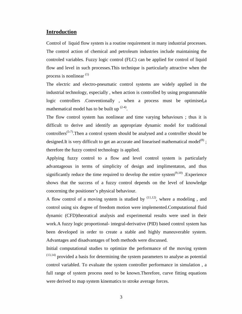
Introduction Control of liquid flow system is a routine requirement in many industrial processes.
The control action of chemical and petroleum industries include maintaining the
controled variables. Fuzzy logic control (FLC) can be applied for control of liquid
flow and level in such processes.This technique is particularly attractive when the
process is nonlinear (1)
The electric and electro-pneumatic control systems are widely applied in the
industrial technology, especially , when action is controlled by using programmable
logic controllers .Conventionally , when a process must be optimised,a
mathematical model has to be built up (2-4).
The flow control system has nonlinear and time varying behaviours ; thus it is
difficult to derive and identify an appropriate dynamic model for traditional
controllers(5-7).Then a control system should be analysed and a controller should be
designed.It is very difficult to get an accurate and linearised mathematical model(8) ;
therefore the fuzzy control technology is applied.
Applying fuzzy control to a flow and level control system is particularly
advantageous in terms of simplicity of design and implimentaton, and thus
significantly reduce the time required to develop the entire system(9,10) .Experience
shows that the success of a fuzzy control depends on the level of knowledge
concerning the positioner’s physical behaviour.
A flow control of a moving system is studied by (11,12)
Initial computational studies to optimize the performance of the moving system
, where a modeling , and
control using six degree of freedom motion were implemented.Computational fluid
dynamic (CFD)theoratical analysis and experimental results were used in their
work.A fuzzy logic proportional- integral-derivative (PID) based control system has
been developed in order to create a stable and highly maneuverable system.
Advantages and disadvantages of both methods were discussed.
(13,14) provided a basis for determining the system parameters to analyse as potential
control variabled. To evaluate the system controller performance in simulation , a
full range of system process need to be known.Therefore, curve fitting equations
were derived to map system kinematics to stroke average forces.
4
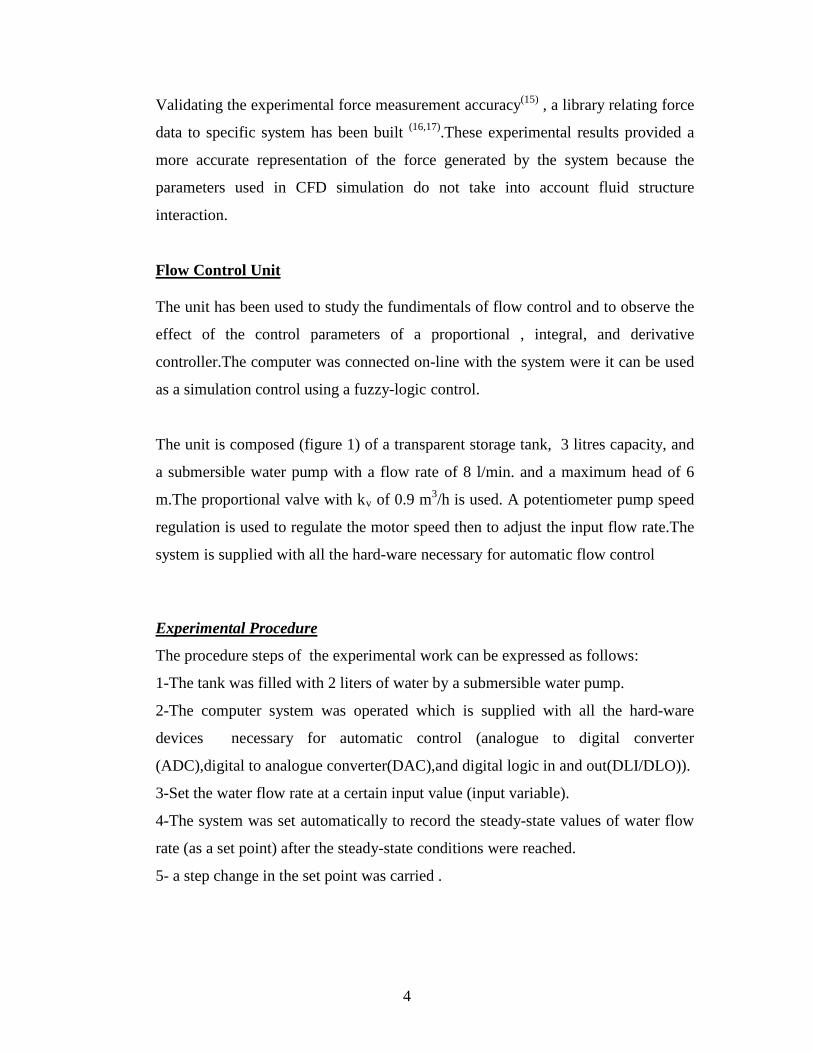
Validating the experimental force measurement accuracy(15) , a library relating force
data to specific system has been built (16,17).These experimental results provided a
more accurate representation of the force generated by the system because the
parameters used in CFD simulation do not take into account fluid structure
interaction.
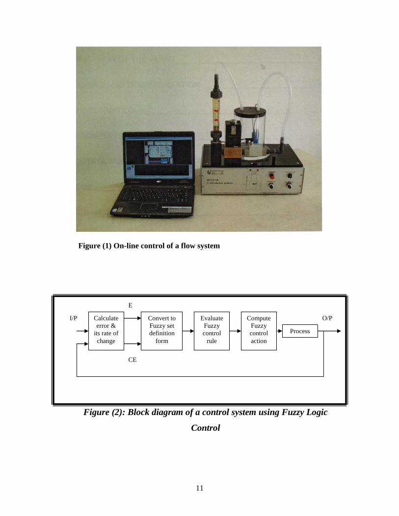
Flow Control Unit The unit has been used to study the fundimentals of flow control and to observe the
effect of the control parameters of a proportional , integral, and derivative
controller.The computer was connected on-line with the system were it can be used
as a simulation control using a fuzzy-logic control.
The unit is composed (figure 1) of a transparent storage tank, 3 litres capacity, and
a submersible water pump with a flow rate of 8 l/min. and a maximum head of 6
m.The proportional valve with kv of 0.9 m3/h is used. A potentiometer pump speed
regulation is used to regulate the motor speed then to adjust the input flow rate.The
system is supplied with all the hard-ware necessary for automatic flow control
Experimental Procedure
The procedure steps of the experimental work can be expressed as follows:
1-The tank was filled with 2 liters of water by a submersible water pump.
2-The computer system was operated which is supplied with all the hard-ware
devices necessary for automatic control (analogue to digital converter
(ADC),digital to analogue converter(DAC),and digital logic in and out(DLI/DLO)).
3-Set the water flow rate at a certain input value (input variable).
4-The system was set automatically to record the steady-state values of water flow
rate (as a set point) after the steady-state conditions were reached.
5- a step change in the set point was carried .
5
6- The control systems were operated to eleminate the error values in water flow
rate(output variable) using different control strategies (P,PI,PID, and Fuzzy-logic
control).
7- The values of the errors in the flow of water versus time were recorded and
plotted by means of a plotter for different control strategies.
Fuzzy Logic Controller:
The purpose of any plant controller is to relate the state variables to action variables.
The controller of a physical system need not itself be physical but may be purely logic.
Furthermore, where known relationships are vague and qualitative. A Fuzzy logic
controller may be constructed to implement the known heuristic. Thus in such a
controller the variables are equated to non-Fuzzy universe given the possible range of
measurement or action magnitudes. These variables, however, take on linguistic values
which are expressed as Fuzzy subset of the universe. The complete procedure of the fuzzy controller design was described (18) :
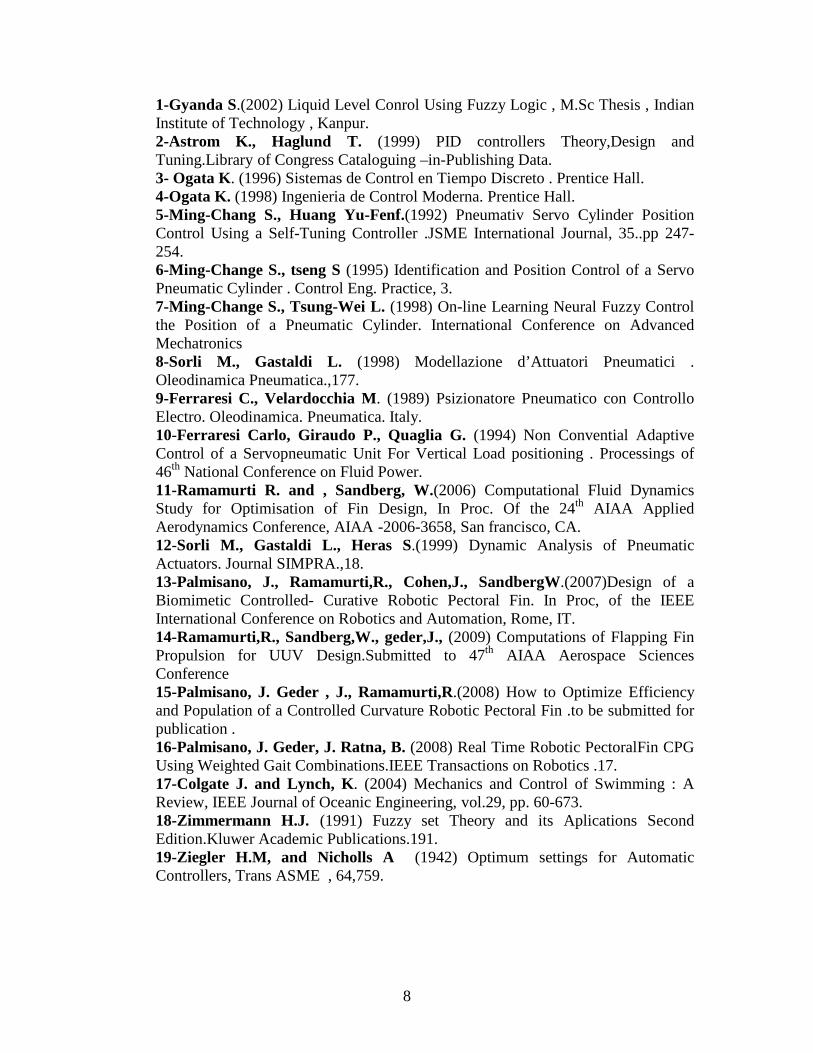
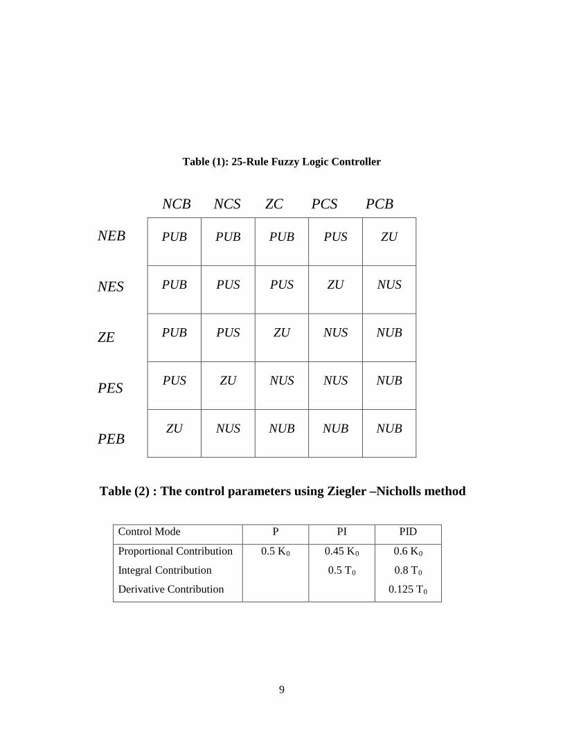
The derivation of the Fuzzy rules can be obtained directly from the phase-plane of error
and its rate of change. Table (1) shows the Fuzzy rules conclusions. The five Fuzzy sets
definition generates (25) rules Fuzzy controller.
The algorithm design steps of a Fuzzy logic controller system shown in figure (2), were
the error (Ei) and rate of change of error (CEi) defines the Fuzzy subsets with their
discrete membership functions.
Control Strategies : In this work two different control strategies were used , feedback and fuzzy logic
control , P,PI and PID controller modes were used as feedback control modes to
control the liquid flow experimentally.
The problem with designing the feedback controller will essentially lie with making
the optimum choice of the most appropriate values to be assigned to the parameters
corresponding to the three contributions "P , I , and ,D " .This choice will not always
be simple as it requires a detailed knowledge of the process to be controlled .
6
There exist several methods aimed at this purpose Ziegler – Nicholls (19) among them
.Depending on the configuration of the variable controller , the parameter shown in
table(2)
The final results will strictly depend on the dynamic behavior of the process being
controlled.
The above optimisation technique was used to determine the optimum values of the
controller parameters ( Kc,τI,and,τD ) to give the minimum value of the integral
square of error , which is defined as :
ISE=∫ E2 (t) dt ……………………………………(1)
The upper limit is t which is a finite time chosen some what arbitrarily so the integral
approaches a steady-state value. It is usually convinient to choose t as the setlling
time.
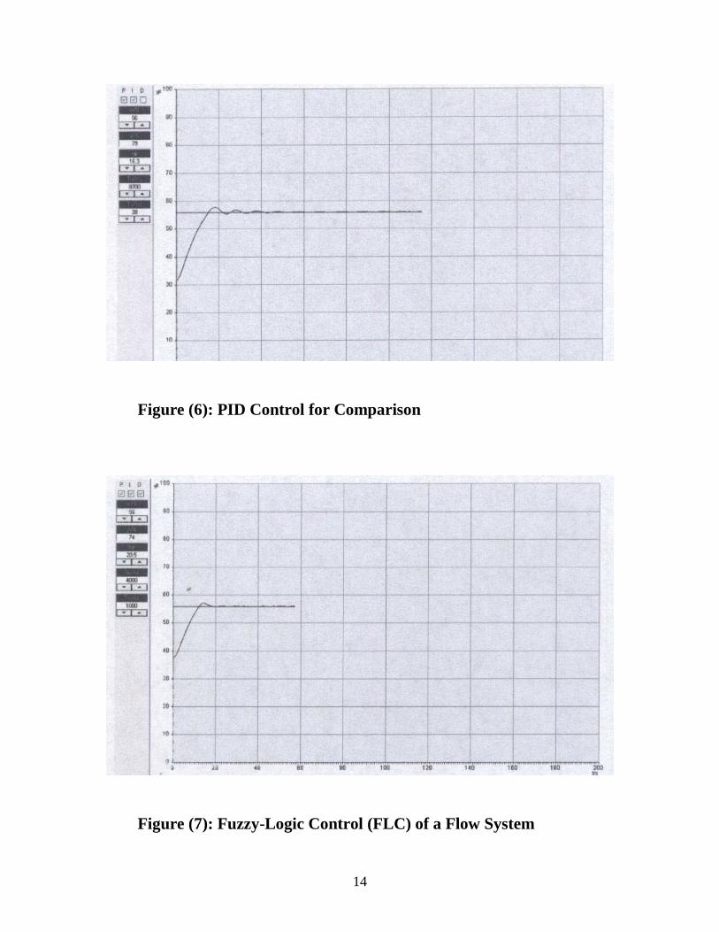
The comparison of fuzzy logic control and PID control is shown in figure(6),and
figure(7), respectively.Fuzzy logic control showed better dynamic control
Results and Discussion In this work a control system was designed and applied to control the liquid flow of a
flow system.
Feedback controllers (P, PI, PID) and fuzzy logic control system(FLC) were
implemented , the optimum control with minimum integral square of error (ISE) was
used as a criteria to compare between fuzzy logic control and PID control.
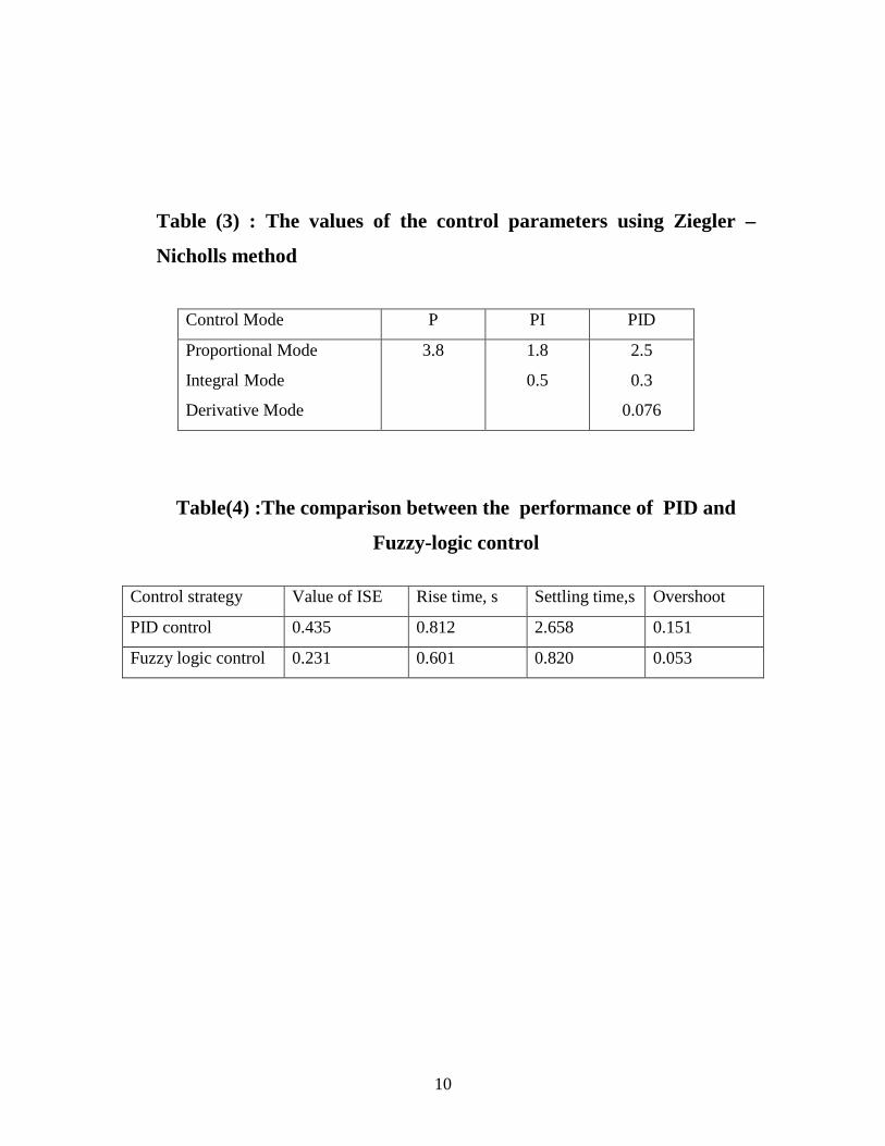
The optimum values of the P, PI, and , PID control parameters using Ziegler-Nicholls
optimum method are given in table (3).
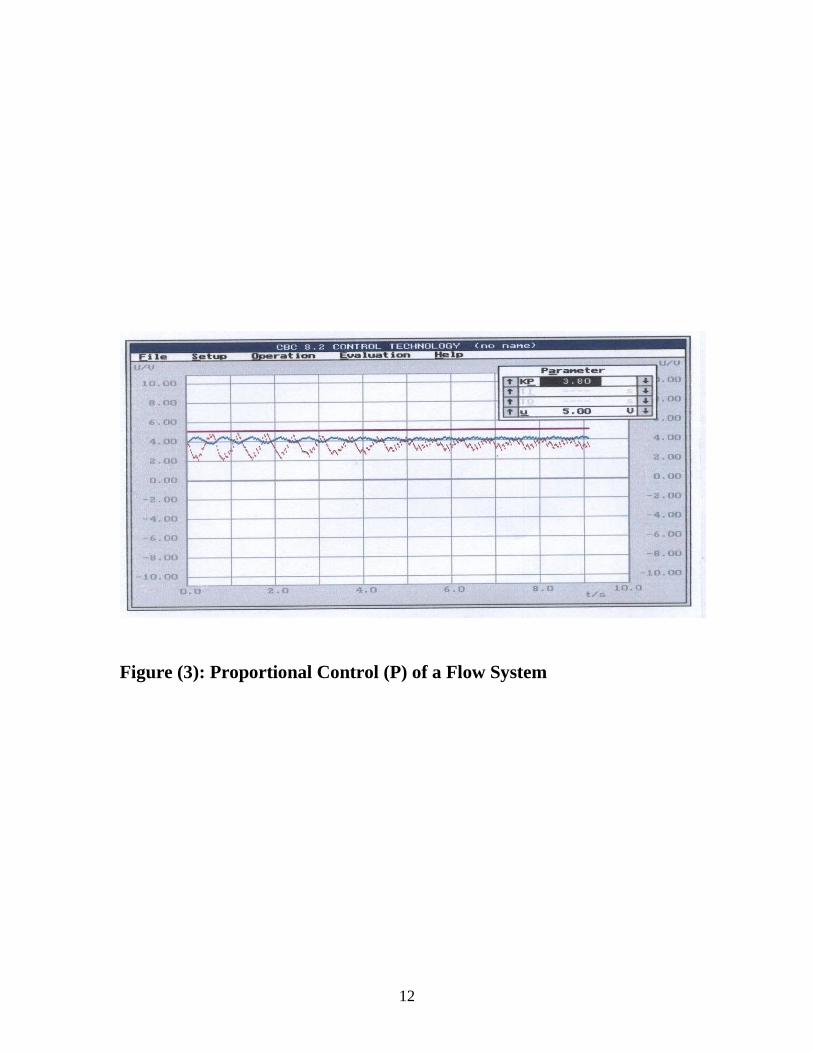
Figures(3-5) show the experimental dynamic response of different feedback control
strategies .Figure(3) shows the control response using P control which shows the
steady-state error of a rate of 0.1257 (offset) as a great disadvantage of this type of
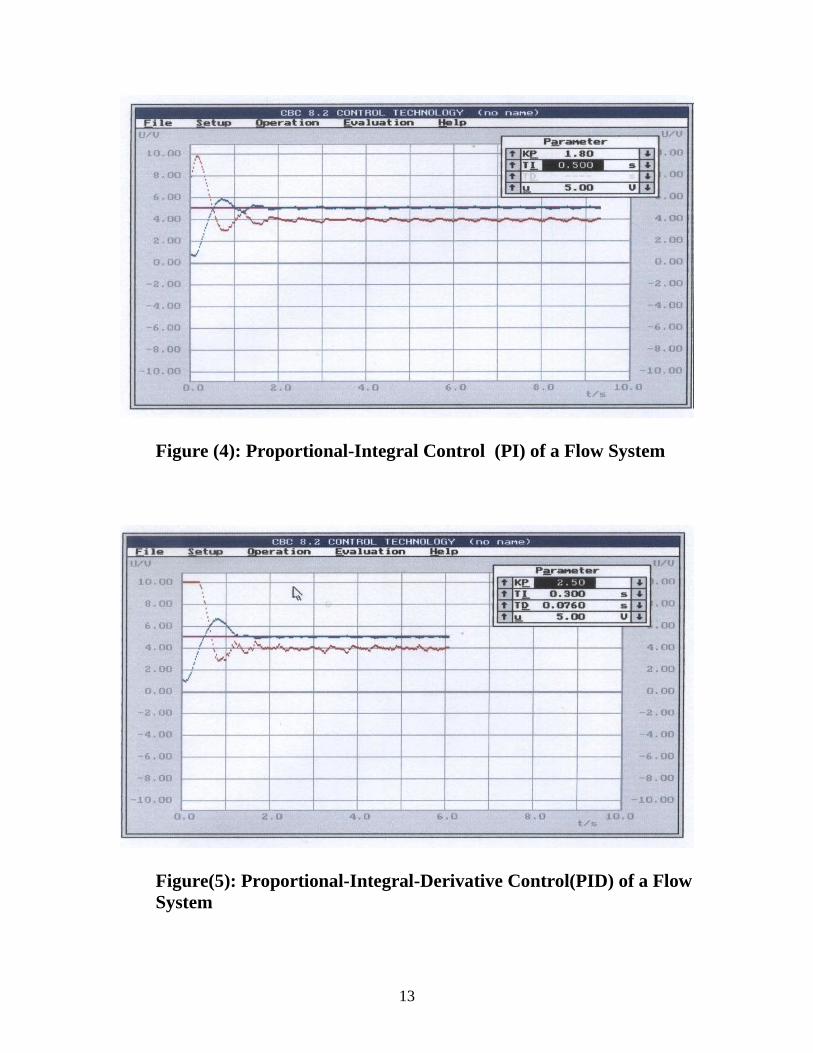
control .This disadvantage was eliminated using PI and PID controls.Figure(4) shows
the oscillation response of PI control which represent one of the disadvantages of this
type. It is clear that PID control mode(figure(5)) gives better response than P, and PI
control with better rise time and settling time.In this work the PID control was used
as a comparison mode with a Fuzzy –logic mode.

7
performance with better rise time, overshoot and response time ,also fuzzy logic
control gives better value of ISE as shown in table (4).The advantage of fuzzy logic
control is that it does not need a model to build the control settings as in the case of
PID controller.
Conclusions In this work it can be concluded that the experimental results of the control system
show that PID controller gave better results than P, and PI controllers .That was
clear from the better rise time and response time.
For the comparison between fuzzy logic control and PID controller ,FLC gave a
marked improvement over PID controller.However the fuzzy controller is
preferable since it does not require an accurate mathematical model for the process
to be controlled, while feedback controllers requires very wide knowledge about the
dynamic behavior and accurate system parameters.
Nomenclatures E : Error in the controlled variable m3/s K0 : Limit value of kp m3/s Kp : Steady-state gain m3/s Kv : Steady-state gain of a control valve m3/s T0 : Period of oscillation s Abbreviations FLC Fuzzy-logic control ISE Integral square of error P Proportional mode PI Proportional-integral mode PID Proportional-integral-derivative mode
References
8
1-Gyanda S.(2002) Liquid Level Conrol Using Fuzzy Logic , M.Sc Thesis , Indian Institute of Technology , Kanpur. 2-Astrom K., Haglund T. (1999) PID controllers Theory,Design and Tuning.Library of Congress Cataloguing –in-Publishing Data. 3- Ogata K. (1996) Sistemas de Control en Tiempo Discreto . Prentice Hall. 4-Ogata K. (1998) Ingenieria de Control Moderna. Prentice Hall. 5-Ming-Chang S., Huang Yu-Fenf.(1992) Pneumativ Servo Cylinder Position Control Using a Self-Tuning Controller .JSME International Journal, 35..pp 247-254. 6-Ming-Change S., tseng S (1995) Identification and Position Control of a Servo Pneumatic Cylinder . Control Eng. Practice, 3. 7-Ming-Change S., Tsung-Wei L. (1998) On-line Learning Neural Fuzzy Control the Position of a Pneumatic Cylinder. International Conference on Advanced Mechatronics 8-Sorli M., Gastaldi L. (1998) Modellazione d’Attuatori Pneumatici . Oleodinamica Pneumatica.,177. 9-Ferraresi C., Velardocchia M. (1989) Psizionatore Pneumatico con Controllo Electro. Oleodinamica. Pneumatica. Italy. 10-Ferraresi Carlo, Giraudo P., Quaglia G. (1994) Non Convential Adaptive Control of a Servopneumatic Unit For Vertical Load positioning . Processings of 46th National Conference on Fluid Power. 11-Ramamurti R. and , Sandberg, W.(2006) Computational Fluid Dynamics Study for Optimisation of Fin Design, In Proc. Of the 24th AIAA Applied Aerodynamics Conference, AIAA -2006-3658, San francisco, CA. 12-Sorli M., Gastaldi L., Heras S.(1999) Dynamic Analysis of Pneumatic Actuators. Journal SIMPRA.,18. 13-Palmisano, J., Ramamurti,R., Cohen,J., SandbergW.(2007)Design of a Biomimetic Controlled- Curative Robotic Pectoral Fin. In Proc, of the IEEE International Conference on Robotics and Automation, Rome, IT. 14-Ramamurti,R., Sandberg,W., geder,J., (2009) Computations of Flapping Fin Propulsion for UUV Design.Submitted to 47th AIAA Aerospace Sciences Conference 15-Palmisano, J. Geder , J., Ramamurti,R.(2008) How to Optimize Efficiency and Population of a Controlled Curvature Robotic Pectoral Fin .to be submitted for publication . 16-Palmisano, J. Geder, J. Ratna, B. (2008) Real Time Robotic PectoralFin CPG Using Weighted Gait Combinations.IEEE Transactions on Robotics .17. 17-Colgate J. and Lynch, K. (2004) Mechanics and Control of Swimming : A Review, IEEE Journal of Oceanic Engineering, vol.29, pp. 60-673. 18-Zimmermann H.J. (1991) Fuzzy set Theory and its Aplications Second Edition.Kluwer Academic Publications.191. 19-Ziegler H.M, and Nicholls A (1942) Optimum settings for Automatic Controllers, Trans ASME , 64,759.
9
Table (1): 25-Rule Fuzzy Logic Controller NCB NCS ZC PCS PCB NEB NES ZE PES PEB
Table (2) : The control parameters using Ziegler –Nicholls method
Control Mode P PI PID
Proportional Contribution
Integral Contribution
Derivative Contribution
0.5 K 0.45 K0 0
0.5 T
0.6 K
0 0
0.8 T0
0.125 T0
PUB PUB PUB PUS ZU
PUB PUS PUS ZU NUS
PUB PUS ZU NUS NUB
PUS ZU NUS NUS NUB
ZU NUS NUB NUB NUB
10
Table (3) : The values of the control parameters using Ziegler –
Nicholls method
Control Mode P PI PID
Proportional Mode
Integral Mode
Derivative Mode
3.8 1.8
0.5
2.5
0.3
0.076
Table(4) :The comparison between the performance of PID and
Fuzzy-logic control
Control strategy Value of ISE Rise time, s Settling time,s Overshoot
PID control 0.435 0.812 2.658 0.151
Fuzzy logic control 0.231 0.601 0.820 0.053
11
Figure (1) On-line control of a flow system
Figure (2): Block diagram of a control system using Fuzzy Logic
Control
Calculate error &
its rate of change
Process
Compute Fuzzy control action
Convert to Fuzzy set definition
form
Evaluate Fuzzy control
rule
E
CE
I/P O/P
12
Figure (3): Proportional Control (P) of a Flow System
13
Figure (4): Proportional-Integral Control (PI) of a Flow System
Figure(5): Proportional-Integral-Derivative Control(PID) of a Flow System
14
Figure (6): PID Control for Comparison
Figure (7): Fuzzy-Logic Control (FLC) of a Flow System