FloTHERM Release Highlights - 易富迪科技FloTHERM Release Highlights, fth12.0 1 July 2017...
55
FloTHERM ® Release Highlights Software Version fth12.0 July 2017 2017 Mentor Graphics Corporation All rights reserved. This document contains information that is proprietary to Mentor Graphics Corporation. The original recipient of this document may duplicate this document in whole or in part for internal business purposes only, provided that this entire notice appears in all copies. In duplicating any part of this document, the recipient agrees to make every reasonable effort to prevent the unauthorized use and distribution of the proprietary information.
Transcript of FloTHERM Release Highlights - 易富迪科技FloTHERM Release Highlights, fth12.0 1 July 2017...
FloTHERM® Release Highlights
Software Version fth12.0
July 2017
2017 Mentor Graphics Corporation All rights reserved.
This document contains information that is proprietary to Mentor Graphics Corporation. The original recipient of this document may duplicate this document in whole or in part for internal business purposes only, provided that this entire notice appears in all copies. In duplicating any part of this document, the recipient agrees to make every reasonable effort to prevent the unauthorized use and distribution of the proprietary information.

This document is for information and instruction purposes. Mentor Graphics reserves the right to make changes in specifications and other information contained in this publication without prior notice, and the reader should, in all cases, consult Mentor Graphics to determine whether any changes have been made.
The terms and conditions governing the sale and licensing of Mentor Graphics products are set forth in written agreements between Mentor Graphics and its customers. No representation or other affirmation of fact contained in this publication shall be deemed to be a warranty or give rise to any liability of Mentor Graphics whatsoever.
MENTOR GRAPHICS MAKES NO WARRANTY OF ANY KIND WITH REGARD TO THIS MATERIAL INCLUDING, BUT NOT LIMITED TO, THE IMPLIED WARRANTIES OF MERCHANTABILITY AND FITNESS FOR A PARTICULAR PURPOSE.
MENTOR GRAPHICS SHALL NOT BE LIABLE FOR ANY INCIDENTAL, INDIRECT, SPECIAL, OR CONSEQUENTIAL DAMAGES WHATSOEVER (INCLUDING BUT NOT LIMITED TO LOST PROFITS) ARISING OUT OF OR RELATED TO THIS PUBLICATION OR THE INFORMATION CONTAINED IN IT, EVEN IF MENTOR GRAPHICS HAS BEEN ADVISED OF THE POSSIBILITY OF SUCH DAMAGES.
U.S. GOVERNMENT LICENSE RIGHTS: The software and documentation were developed entirely at
private expense and are commercial computer software and commercial computer software
documentation within the meaning of the applicable acquisition regulations. Accordingly, pursuant to
FAR 48 CFR 12.212 and DFARS 48 CFR 227.7202, use, duplication and disclosure by or for the U.S.
Government or a U.S. Government subcontractor is subject solely to the terms and conditions set forth
in the license agreement provided with the software, except for provisions which are contrary to
applicable mandatory federal laws.
TRADEMARKS: The trademarks, logos and service marks ("Marks") used herein are the property of Mentor Graphics Corporation or other parties. No one is permitted to use these Marks without the prior written consent of Mentor Graphics or the owner of the Mark, as applicable. The use herein of a third- party Mark is not an attempt to indicate Mentor Graphics as a source of a product, but is intended to indicate a product from, or associated with, a particular third party. A current list of Mentor Graphics’ trademarks may be viewed at: www.mentor.com/trademarks.
The registered trademark Linux® is used pursuant to a sublicense from LMI, the exclusive licensee of
Linus Torvalds, owner of the mark on a world-wide basis.
End-User License Agreement: You can print a copy of the End-User License Agreement from: www.mentor.com/eula.
Mentor Graphics Corporation
8005 S.W. Boeckman Road, Wilsonville, Oregon 97070-7777. Telephone: 503.685.7000
Toll-Free Telephone: 800.592.2210 Website: www.mentor.com
SupportNet: supportnet.mentor.com/
Send Feedback on Documentation: supportnet.mentor.com /doc_feedback_form

FloTHERM Release Highlights, fth12.0 1 July 2017
Introduction This document provides a high-level summary of this release. It includes a summary of the new features in
this release, any authorization code changes required, any major installation changes, and any transitioning
issues you should be aware of before installing.
This document is located on the CD and on SupportNet. Changes may be added to this document after the
release. Refer to the Release Highlights documents on SupportNet for the most up-to-date release
information
New Features The following new features are available in this release:
Platform Support
Ref. Title Description
1.1 32-bit Operating
Systems no longer
supported
FloTHERM v12.0 does not support 32-bit operating systems.
1.2 Linux Linux Red Hat 5 is no longer supported. FloTHERM v12 only
supports Red Hat 6.

2 FloTHERM Release Highlights, fth12.0 July 2017
Command Center
Ref. Title Description
2.1 Re-implemented
Command Center
window
Command Center is a launchable window as before. The primary
functionality is spread over 5 tabs at the bottom of the window:
Input Variables: Define what model inputs can change
Output Variables: Define what results are extracted
Scenario Table: Define scenarios and view numerical results
Scenario Viewer: Visualize the defined scenarios
Solution Monitoring: Inspect Residual and Monitor Point plots.
2.2 64 bit operation Command Center is now a 64-bit application.
2.3 Scenario selection
linking
Scenarios selected in a tab are automatically selected in all other tabs
and charts. This facilitates the inspection of parametric setup and
analysis of the results.
2.4 Object Selection
Linking
Objects selected in a tab are automatically selected in all other tabs, and
also in the Project Manager. This facilitates the nomination of input
and output variables, as well as inspection of the scenarios in the
Scenario Viewer.

FloTHERM Release Highlights, fth12.0 3 July 2017
Ref. Title Description
2.5 Consistent Controls View manipulation in Command Center is identical to view
manipulation in the Drawing Board.
Node tree controls are identical as well. The same keyboard shortcuts
are supported in Command Center as well (F4-F6 to collapse-expand
the tree, F9 to toggle mouse mode, etc)
2.6 Full Undo/Redo
support
Unlimited number of undo/redo steps can be performed. Undo/Redo
commands are available in the top level toolbar.
2.7 FloSCRIPT support Every action in Command Center has an equivalent FloSCRIPT
command. All aspects of Command Center can be fully automated.
2.8 In Sync with Project
Manager model
Any change made to the base model in the Project Manager and
Drawing Board will automatically be applied to the scenarios present in
Command Center.
If the change will cause scenario results to become out of date, then the
user is prompted to save the model with a new name.
2.9 Command Center
shown in Project
Load
When input variables or output variables have been activated in
Command Center, this is indicated in the Project/Load dialog.

4 FloTHERM Release Highlights, fth12.0 July 2017
Ref. Title Description
2.10 Automatic Response
Surface Calculation
When possible, Response Surfaces are automatically calculated after
all active scenario solves are finished. Response Surfaces can be
visualized from the Chart\ Response Surface Viewer menu. See
Section 10 for additional information on Response Surfaces.
2.11 Response Surface
Prerequisites
Design Parameters are no longer a pre-requisite for response surface
creation. Any numerical input variable is supported, with the range
automatically extracted from the defined scenarios.
A cost function is no longer required for response surface creation.
2.12 Scenario File
structure
The scenario file is used to store the state of the Command Center. It is
now XML based and amenable to scripting applications.
2.13 Message Window The Command Center has a dedicated message window. All
Command Center related messages are displayed here.
2.14 Retention of Post-
Processing and CC
Setup
When a scenario is saved as a separate FloTHERM model, the state of
the Visual Editor is copied to the new project. All previously defined
post-processing plots are retained and immediately available in the new
model.
Any defined Input and Output Variables are copied to the new project
as well to facilitate further design space exploration.

FloTHERM Release Highlights, fth12.0 5 July 2017
Command Center – Input Variables
Ref. Title Description
3.1 Inputs available in
same location as
Project Manager
Objects, attributes, and model settings are presented in the same
location as in the Project Manager. The structure of the Input Variable
node tree is identical to the baseline model.

6 FloTHERM Release Highlights, fth12.0 July 2017
Ref. Title Description
3.2 Display Area The baseline model is displayed in the Input Variables tab to facilitate
object selection and parametric setup comprehension.
3.3 Input Variables
Table
All nominated input variables are placed in a table under the graphics
display area. The input variable name, type, a description, and the
defined range of the variable are presented.
The type of the input variable can be modified from the table, and
further defined in the area to the right of the table.
Input variables can be removed with the ‘-‘ button.

FloTHERM Release Highlights, fth12.0 7 July 2017
Ref. Title Description
3.4 Property Sheet
Nomination
Model parameters are nominated as input variables by checking a box
near the parameter in a property sheet. Unchecking the box
unnominates the parameter. Multiple selections are supported.
3.5 Variable Type
Support
Three types of input variables can be defined:
-Default
-Design Parameter. User must define a valid range for the parameter.
The range is used for all optimization and calibration tasks.
-Dependent Variable. User must define an expression that relates this
input variable to other existing variables.
3.6 Design Parameter In the area to the right of the table, define the minimum and maximum
values of the input variable.

8 FloTHERM Release Highlights, fth12.0 July 2017
Ref. Title Description
3.7 Dependent Variable
Equation
An equation editor is available from the area to the right of the table.
The equation editor supports addition, subtraction, multiplication, and
division of input variables and constants. Terms may be grouped with
parentheses. This enables some non-linear equations to be supported.
Note: the defined equation must be valid for the baseline model. A
constant is automatically evaluated during equation definition to ensure
this is the case.
Any Input Variable can be used, even other Dependent Variables. A
circular expression cannot be used however (i.e., a dependent variable
cannot be dependent upon itself).
FloTHERM Release Highlights, fth12.0 9 July 2017
Ref. Title Description
3.8 Network Assembly
R and C support
Network Assembly Resistances and Capacitances can be used as Input
Variables.
3.9 Compact Component
R Support
Compact Component Resistances can be used as Input Variables.
3.10 Ignored setting for
Assemblies as Input
Variable
The ignored setting for assemblies can be nominated as an Input
Variable.

10 FloTHERM Release Highlights, fth12.0 July 2017
Ref. Title Description
3.11 Non-Linear Source
Attribute: Powers
available as Input
Variables
Powers defined in a non-linear source attribute can be nominated as
Input Variables.
Note: the temperatures in this attribute cannot be nominated.
3.12 Transient
Termination Monitor
Point control as
Input Variables
Transient Termination Monitor Point control temperatures can be
nominated as Input Variables.

FloTHERM Release Highlights, fth12.0 11 July 2017
Ref. Title Description
3.13 Find Support The Find tool is fully supported in Command Center. Note that the
extension to the Find tool allowing attributes to be found (see item
19.2) is supported in Command Center as well.
Command Center – Output Variables
Ref. Title Description
4.1 Node Tree replicates
the Project Manager
The Output Variables node tree has the same structure as the baseline
model in the Project Manager. SmartParts are exceptions however,
also displaying constituent objects when appropriate.

12 FloTHERM Release Highlights, fth12.0 July 2017
Ref. Title Description
4.2 Tabbed Property
Sheet Nomination
Each object in the node tree will have a property sheet from which
Output Variables can be nominated. Multiple selections are supported.
The property sheet is categorized by Output Variable type. Each type
will have a tab present if such data is valid for a particular object.
The categories are:
• Data: Object specific data
• Heat Transfer: Conduction, convection, radiation heat flux
results
• Temperature: Surface temperatures and face based
temperature results
• Fluid Flow: Volume flow, mass flow and pressure drop results.
• Region Data: Min, Max, Mean results
• Area: Object face areas
Several categories can be filtered to reduce the number of options
displayed.
Heat Transfer for example, can be filtered by conduction, convection,
and radiation quantities.
FloTHERM Release Highlights, fth12.0 13 July 2017
Ref. Title Description
4.3 Field Summary Tab Legacy ‘Field Summary’ Output Variables are now available in a tab
above the node tree. The property sheet filters are C = Common, A =
Auxiliary Variables, and M = Miscellenaeous
4.4 Metrics Tab Legacy ‘Metrics’ Output Variables are now available in a tab above the
node tree.

14 FloTHERM Release Highlights, fth12.0 July 2017
Ref. Title Description
4.5 Output Variables
Table
A table is presented under the graphics area to list the nominated
Output Variables.
An Output Variable can be included in the Cost Function definition
from here.
4.6 Network Assembly
Node Temperatures
and Fluxes as Output
Variables
Network Assembly Node Temperatures and Fluxes are now available
as Output Variables.
Command Center – Scenario Table
Ref. Title Description
5.1 Input Variables and
Output Variables
Displayed in tabular
form
Input Variables are listed in the top section of the scenario, and Output
Variables are listed in the bottom section. The sections are separated
by the solver status and control rows.

FloTHERM Release Highlights, fth12.0 15 July 2017
Ref. Title Description
5.2 Append New
Scenario column
An Append New Scenario column is always available to the right of the
last scenario. Adding values to any of these cells will create a new
scenario. Any undefined values are inherited from the adjacent
column.
Values can be added by typing, or pasting from other cells or the
clipboard.

16 FloTHERM Release Highlights, fth12.0 July 2017
Ref. Title Description
5.3 Modify Attribute
Type Input Variables
with Drop Down
List
Input Variables that are lists (usually attribute attachments) are
modified by clicking the cell, and selecting the new value from a drop
down list that appears.
5.4 Modify numerical
input variable values
by typing
Any numerical input variable can be modified by typing the new value
into the cell.
5.5 Copy cell values Cells may be copied by selecting cells and right clicking to use the
Copy option that appears. CTRL-C is also supported.
The row and column headers can be included by ensuring that they are
included in the set of selected cells.

FloTHERM Release Highlights, fth12.0 17 July 2017
Ref. Title Description
5.6 Paste into Input
Variable cells
Data can be pasted into Input Variable cells. Incoming data will
overwrite the existing cell data.
Data can be pasted into the Append Scenario column to create new
scenarios.
If the array of data being pasted exceeds the available target cells, then
the additional data is used to create additional scenarios.
Note: Attribute names can be pasted as well, but the pasted data must
match an existing attribute or it will be ignored.
Note: Dependent variables are read-only and can never be overwritten
with pasted data.

18 FloTHERM Release Highlights, fth12.0 July 2017
Ref. Title Description
5.7 Individual Scenario
commands
Individual scenarios can be selected by clicking the column header.
Scenario commands are available via a right click.
5.8 Remove Variables Input and Output Variables may be removed via a right click with the
appropriate Scenario Table row selected.
5.9 Solution and
Initialization
controls
As in previous versions, controls are available for the level of data to be
stored for each scenario (Full, History Only, None) and to specify what
scenario is to be used for solver initialization purposes.
Note: If ‘Initialize From’ is set to ‘No Project’ for a scenario, then that
scenario will initialize based on the settings made in the ‘Initial
Variables’ section of the ‘Solver Control’ tab in the base project.
5.10 Scenario Status The solution status row displays the current status of each scenario. If
a scenario is currently being solved, a progress bar is displayed in that
scenario table cell to give a rough indication of solver progress.
5.11 Create Scenarios
Menu
A new top level menu is present that contains all of the scenario
creation tools.
• Linear Sweep [new functionality. See item 5.12]
• Add Variables [legacy functionality]
• Multiply Variables [legacy functionality]
• Design of Experiments [legacy functionality]
• Superposition [new functionality. See item 5.13]
FloTHERM Release Highlights, fth12.0 19 July 2017
Ref. Title Description
5.12 Linear Sweep Similar to the legacy ‘Linear’ variation command, but allowing
multiple variables to be considered at once. The defined linear
variation will be applied to all variables that are selected.

20 FloTHERM Release Highlights, fth12.0 July 2017
Ref. Title Description
5.13 Superposition
Scenario Creation
Tool
A tool to facilitate scenario setup for superposition analysis. The
superposition method requires that a single power be active for each
scenario.
A list of all ‘total power’ type Input Variables is displayed and can be
added to the analysis. The Create Superposition tool will create one
scenario for each Input Variable added. The user can choose a custom
power to be applied for all scenarios, or choose to take the power from
the baseline model.
Note: A supporting spreadsheet (Superposition.xlsm) is provided that
expects as input the contents of the scenario table, and produces as
output an instantaneous temperature prediction for all power sources.
5.14 Cost Function
Display via tooltip
Hovering the mouse cursor over the Cost Function row will display the
cost function definition in a tooltip.
5.15 Find Min/Max
values for any
Output Variable
The minimum or maximum value for an Output Variable can be found
with a right click on the row header. The appropriate scenario will be
selected, and the scenario table will scroll if necessary to ensure the
selection is visible on screen.

FloTHERM Release Highlights, fth12.0 21 July 2017
Ref. Title Description
5.16 User Preferences User preferences are available for:
Solving:
• Remote vs Local
• Number of Concurrent Jobs
• Number of Processors to use per job.
Results:
• Significant Figures used to display Output Variables
Command Center – Scenario Viewer
Ref. Title Description
6.1 Scenario List A list of all defined scenarios is shown on the left. Selection of a
scenario in the list will update the node tree and graphics display to
show that scenario.
6.2 Graphics Display
Area
The graphics area will display the geometry associated with the
selected scenario.
6.3 Full Model Node
and Attribute Tree
The model node tree and attribute tree will display the model definition
for the selected scenario.

22 FloTHERM Release Highlights, fth12.0 July 2017
Ref. Title Description
6.4 Grid
Display/Workplane
controls
The computational grid for a scenario can be displayed with ‘g’ key as
in the Drawing Board. The workplane can be positioned anywhere in
model using the controls in the top toolbar as in the Drawing Board.
6.5 Scenario selection
linking with other
areas
Selecting a scenario in the Scenario Viewer tab will cause that scenario
to be selected in all other tabs.

FloTHERM Release Highlights, fth12.0 23 July 2017
Command Center – Solution Monitoring
Ref. Title Description
7.1 Scenario List A list of all defined scenarios is shown on the left. Selection of a
scenario in the list will update the Profiles plots (typically Residuals
and Monitor Point plots) on the right.
7.2 Profiles plot
replicated for
scenarios
The plots defined in the Profiles window for the base model are
replicated in the Solution Monitoring tab. Plots cannot be created or
modified within Command Center.
7.3 Scenario selection
linking with other
areas
Selecting a scenario in the Solution Monitoring tab will cause that
scenario to be selected in all other tabs.

24 FloTHERM Release Highlights, fth12.0 July 2017
Command Center – Charts
Ref. Title Description
8.1 Chart Command A ‘Chart’ menu is available. This contains options for Chart creation,
Response Surface viewing [see Section 10] and a list of any previously
defined charts.
8.2 Chart Title A name can be assigned to the chart.
8.3 X-Axis Variable The x-axis variable for the chart is selected from a drop down list. The
list will contain all numerical Input Variables, all Output Variables, and
the Scenario Number.
FloTHERM Release Highlights, fth12.0 25 July 2017
Ref. Title Description
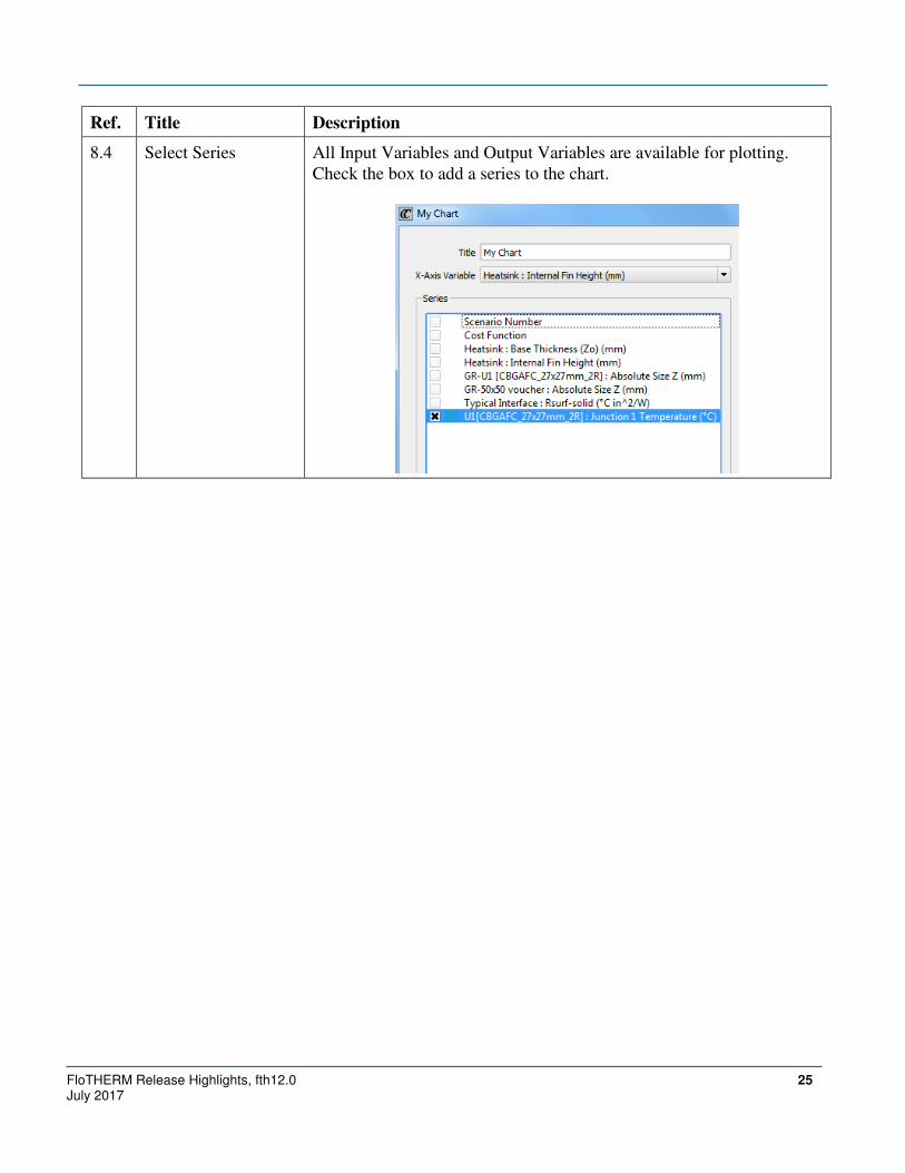
8.4 Select Series All Input Variables and Output Variables are available for plotting.
Check the box to add a series to the chart.

26 FloTHERM Release Highlights, fth12.0 July 2017
Ref. Title Description
8.5 Set Series Color The color for each series can be set. There are two options:
1. Pick a color from the provided palette.
2. Color the series scaled by the values of another Input or Output
Variable. Note: the color range for this additional scalar is not
modifiable.
FloTHERM Release Highlights, fth12.0 27 July 2017
Ref. Title Description
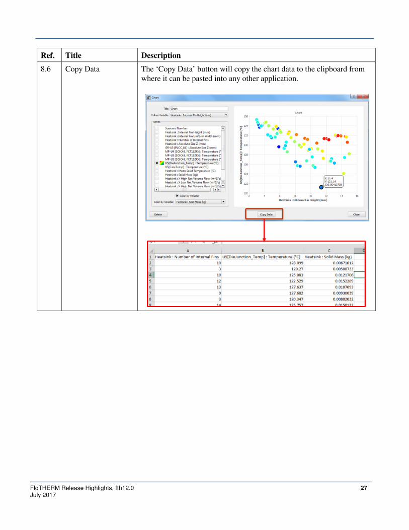
8.6 Copy Data The ‘Copy Data’ button will copy the chart data to the clipboard from
where it can be pasted into any other application.

28 FloTHERM Release Highlights, fth12.0 July 2017
Ref. Title Description
8.7 Annotate Chart
Points
Moving the mouse over a chart point will display a tool tip that
provides the XY values of the point, and also the value of the ‘color by
variable’ chosen for that series if applicable.
Double-clicking a chart marker will fix the tooltip to the chart point.
Double-clicking the fixed tooltip will remove it.
8.8 Selection linking
with other areas
Click a chart marker to select it. The associated scenario will be
selected in all the tabs.

FloTHERM Release Highlights, fth12.0 29 July 2017
Command Center – Optimization
Ref. Title Description
9.1 Legacy Functionality All legacy optimization functionality has been re-implemented.

30 FloTHERM Release Highlights, fth12.0 July 2017
Ref. Title Description
9.2 Improved input and
output constraint
interface
Input and Output constraints can be defined as in previous versions.
The definition of the constraints is now performed within the
optimization dialog, with one row used per variable in the expression.
9.3 Unsolved Scenarios
solved prior to
optimizing
Any unsolved scenarios present are automatically solved prior to
commencing the optimization method. It is no longer a pre-requisite
that all scenarios be solved before defining an optimization task.
FloTHERM Release Highlights, fth12.0 31 July 2017
Command Center – Response Surfaces
Ref. Title Description
10.1 Response Surface
Viewer
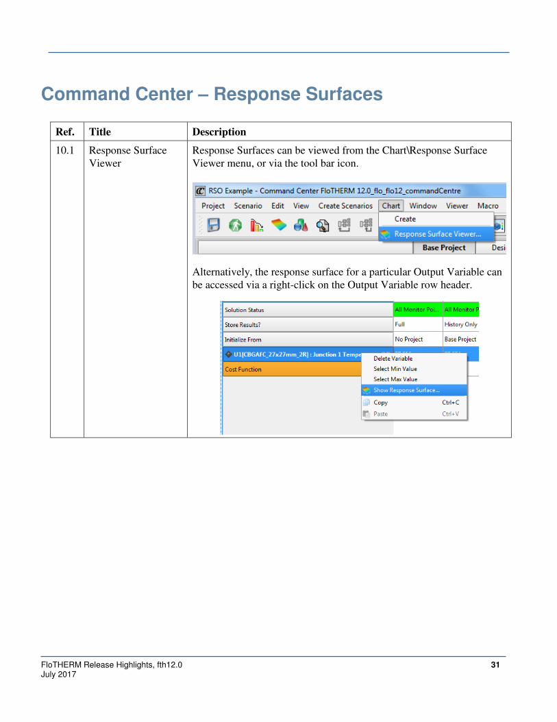
Response Surfaces can be viewed from the Chart\Response Surface
Viewer menu, or via the tool bar icon.
Alternatively, the response surface for a particular Output Variable can
be accessed via a right-click on the Output Variable row header.

32 FloTHERM Release Highlights, fth12.0 July 2017
Ref. Title Description
10.2 Available Response
Surfaces listed
All available response surfaces are listed in the Plots tab. Checking a
box will activate the display of that response surface.
FloTHERM Release Highlights, fth12.0 33 July 2017
Ref. Title Description
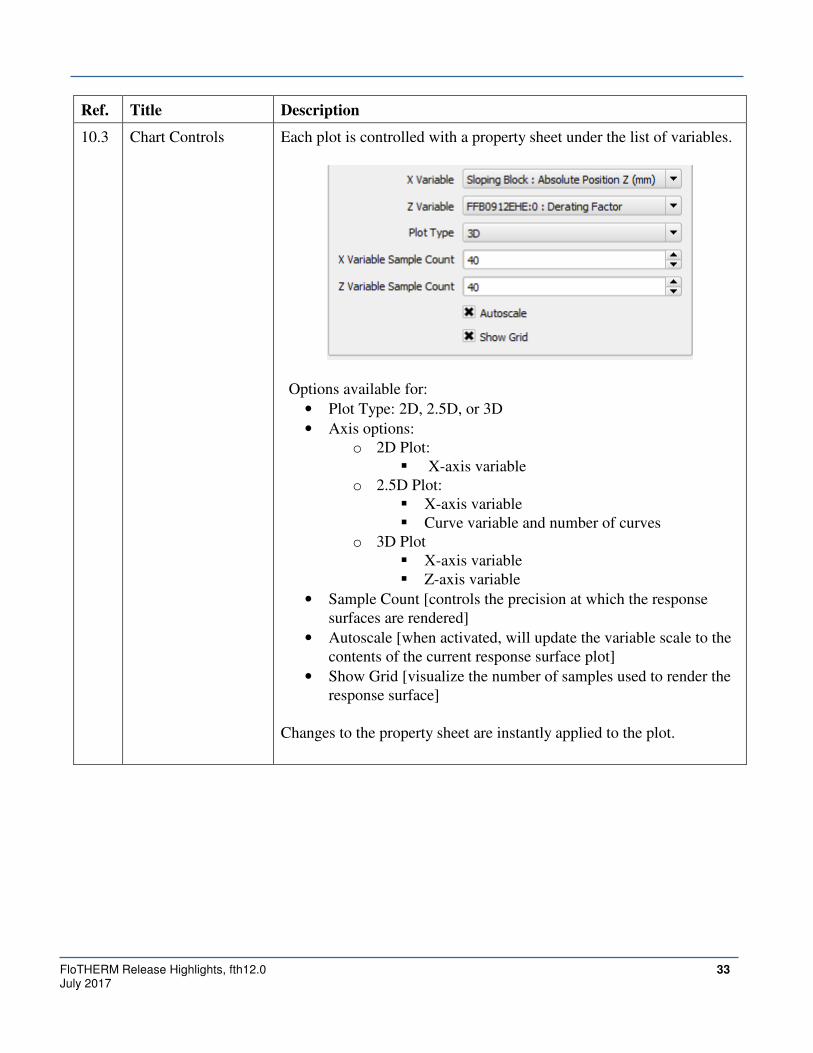
10.3 Chart Controls Each plot is controlled with a property sheet under the list of variables.
Options available for:
• Plot Type: 2D, 2.5D, or 3D
• Axis options:
o 2D Plot:
� X-axis variable
o 2.5D Plot:
� X-axis variable
� Curve variable and number of curves
o 3D Plot
� X-axis variable
� Z-axis variable
• Sample Count [controls the precision at which the response
surfaces are rendered]
• Autoscale [when activated, will update the variable scale to the
contents of the current response surface plot]
• Show Grid [visualize the number of samples used to render the
response surface]
Changes to the property sheet are instantly applied to the plot.

34 FloTHERM Release Highlights, fth12.0 July 2017
Ref. Title Description
10.4 Variable Control The values for input variables not used for a plot axis can be controlled
with slider bar inputs in the Variables tab. All response surface plots
update instanteously to any change in these values.
10.5 2D Plots

FloTHERM Release Highlights, fth12.0 35 July 2017
Ref. Title Description
10.6 2.5D Plots A 2D plot extended to show curves of various values of another input
variable. The number of curves displayed is controlled in the settings
tab.

36 FloTHERM Release Highlights, fth12.0 July 2017
Ref. Title Description
10.7 3D Plots
Clicking the surface will highlight the clicked point and produce a
tooltip with the point xyz coordinates. The slider bars in the Variable
tab will update to display the click coordinates.
10.8 Plot View
Manipulation
The view of the plots can be manipulated with the following controls:
• 2D and 2.5D Plots
o Left mouse button to draw zoom extents
o Mouse wheel dynamic zoom
o Right mouse click to reset view
• 3D Plots
o Mouse wheel dynamic zoom
o Right mouse button to rotate view
o x, y, and z keyboard shortcuts to align the view with the
corresponding axis.
FloTHERM Release Highlights, fth12.0 37 July 2017
Ref. Title Description
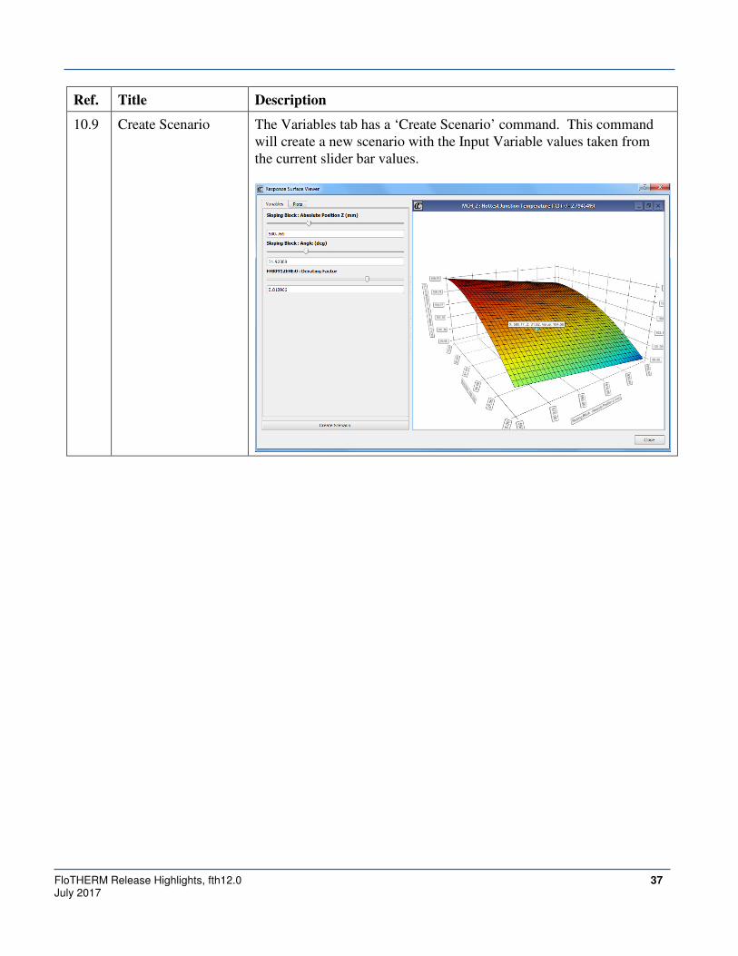
10.9 Create Scenario The Variables tab has a ‘Create Scenario’ command. This command
will create a new scenario with the Input Variable values taken from
the current slider bar values.

38 FloTHERM Release Highlights, fth12.0 July 2017
Profiles Window
Ref. Title Description
11.1 Dockable window Profiles can be docked and undocked via a toggle on the toolbar.
In the docked state, Profiles can be also be undocked by double
clicking the Profiles title bar (see image below)
11.2 Tile Plots A Tile Plots command is available to fill the available plot space within
the Profiles window with the defined plots. This can be used when the
Profiles window is resized to increase visibility of the plots.
11.3 Default Plots As in previous versions, default plots are created on model creation.
For Steady State models: Residual vs Iteration and Monitor Points vs
Iteration
For Transient models: Residual Iterations vs Time and Monitor Point
vs Time

FloTHERM Release Highlights, fth12.0 39 July 2017
Ref. Title Description
11.4 Plot Creation Profiles\Create Plot can be used to create additional plots. The plots
available match those supported in previous versions.
11.5 Monitor Point
selection linking
Selecting a Monitor Point in the model tree will cause the associated
curves and legend entries to stand out in all Monitor Point profile plots.
11.6 Scrollable Monitor
Point legend
Models with a large number of Monitor Points will have a scrollable
legend to ensure that all Monitor Points can be displayed in the plot.
11.7 Zoom Options The view extents of profile plots are controlled by:
• Right-click, choose Edit Settings or
• Use the Left Mouse Button to draw a Zoom Rectangle (a right
mouse button click will reset the view extents)
40 FloTHERM Release Highlights, fth12.0 July 2017
Ref. Title Description
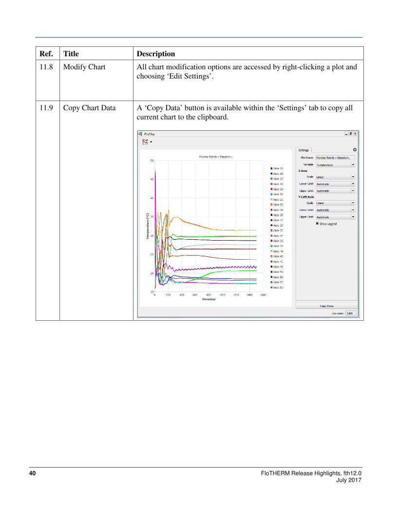
11.8 Modify Chart All chart modification options are accessed by right-clicking a plot and
choosing ‘Edit Settings’.
11.9 Copy Chart Data A ‘Copy Data’ button is available within the ‘Settings’ tab to copy all
current chart to the clipboard.
FloTHERM Release Highlights, fth12.0 41 July 2017
Phase Change Materials
Ref. Title Description
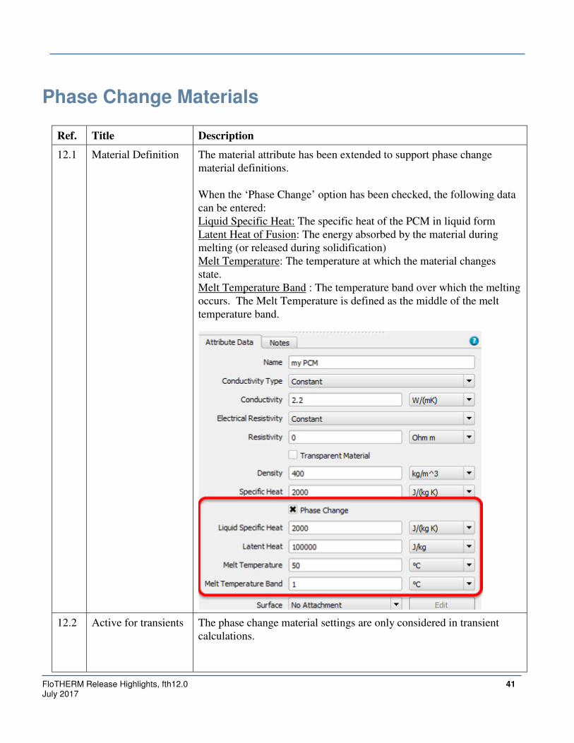
12.1 Material Definition The material attribute has been extended to support phase change
material definitions.
When the ‘Phase Change’ option has been checked, the following data
can be entered:
Liquid Specific Heat: The specific heat of the PCM in liquid form
Latent Heat of Fusion: The energy absorbed by the material during
melting (or released during solidification)
Melt Temperature: The temperature at which the material changes
state.
Melt Temperature Band : The temperature band over which the melting
occurs. The Melt Temperature is defined as the middle of the melt
temperature band.
12.2 Active for transients The phase change material settings are only considered in transient
calculations.

42 FloTHERM Release Highlights, fth12.0 July 2017
Ref. Title Description
12.3 Melt Fraction scalar
field
A ‘melt fraction’ scalar is computed during the solution and available
for post-processing. Melt Fraction has a range of 0-1, with 0 indicating
completely solid, and 1 indicating completely liquid.
Melt Fraction can be used like any other scalar in the Visual Editor and
is available for Monitor Point vs Time plots in Profiles.
12.4 Time grid
requirements
Enthalpy is solved for directly within all Phase Change Material solids.
As a result, the latent heat will be included in the results regardless of
the defined time step distribution. There is no requirement to place a
time step at the melt start or end points.
12.5 Convergence
recommendations
Convergence for models with Phase Change Materials can be better
assured when:
• Double Precision is activated
• The number of Outer Iterations is increased ( the default of 500
can be insufficient in some applications to allow convergence
for all time steps).
ODB++ Import
Ref. Title Description
13.1 FloEDA Bridge
ODB++ Import
Command
An ODB++ archive file (.tgz, .tar, .tar.gz formats) or an ODB++
directory can be imported into FloEDA Bridge.

FloTHERM Release Highlights, fth12.0 43 July 2017
Ref. Title Description
13.2 Import Layout, Stack
up, images for all
layers
Importing ODB++ data will create the board outline, component layout,
layer stack-up (including dielectric layers; see Section 14.1), and black
and white images for each layer.

44 FloTHERM Release Highlights, fth12.0 July 2017
Blind and Buried Vias
Ref. Title Description
14.1 Dielectric Layer Each layer in the stack up can now be designated as a ‘Metallic’ or
‘Dielectric’ type. Both layer types can be image processed to create a
tiled material map for that layer.
FloTHERM Release Highlights, fth12.0 45 July 2017
Ref. Title Description
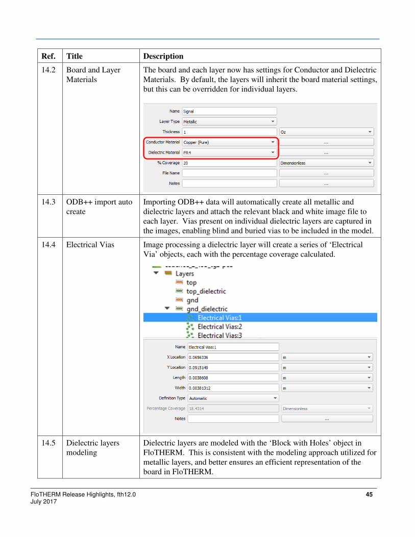
14.2 Board and Layer
Materials
The board and each layer now has settings for Conductor and Dielectric
Materials. By default, the layers will inherit the board material settings,
but this can be overridden for individual layers.
14.3 ODB++ import auto
create
Importing ODB++ data will automatically create all metallic and
dielectric layers and attach the relevant black and white image file to
each layer. Vias present on individual dielectric layers are captured in
the images, enabling blind and buried vias to be included in the model.
14.4 Electrical Vias Image processing a dielectric layer will create a series of ‘Electrical
Via’ objects, each with the percentage coverage calculated.
14.5 Dielectric layers
modeling
Dielectric layers are modeled with the ‘Block with Holes’ object in
FloTHERM. This is consistent with the modeling approach utilized for
metallic layers, and better ensures an efficient representation of the
board in FloTHERM.
46 FloTHERM Release Highlights, fth12.0 July 2017
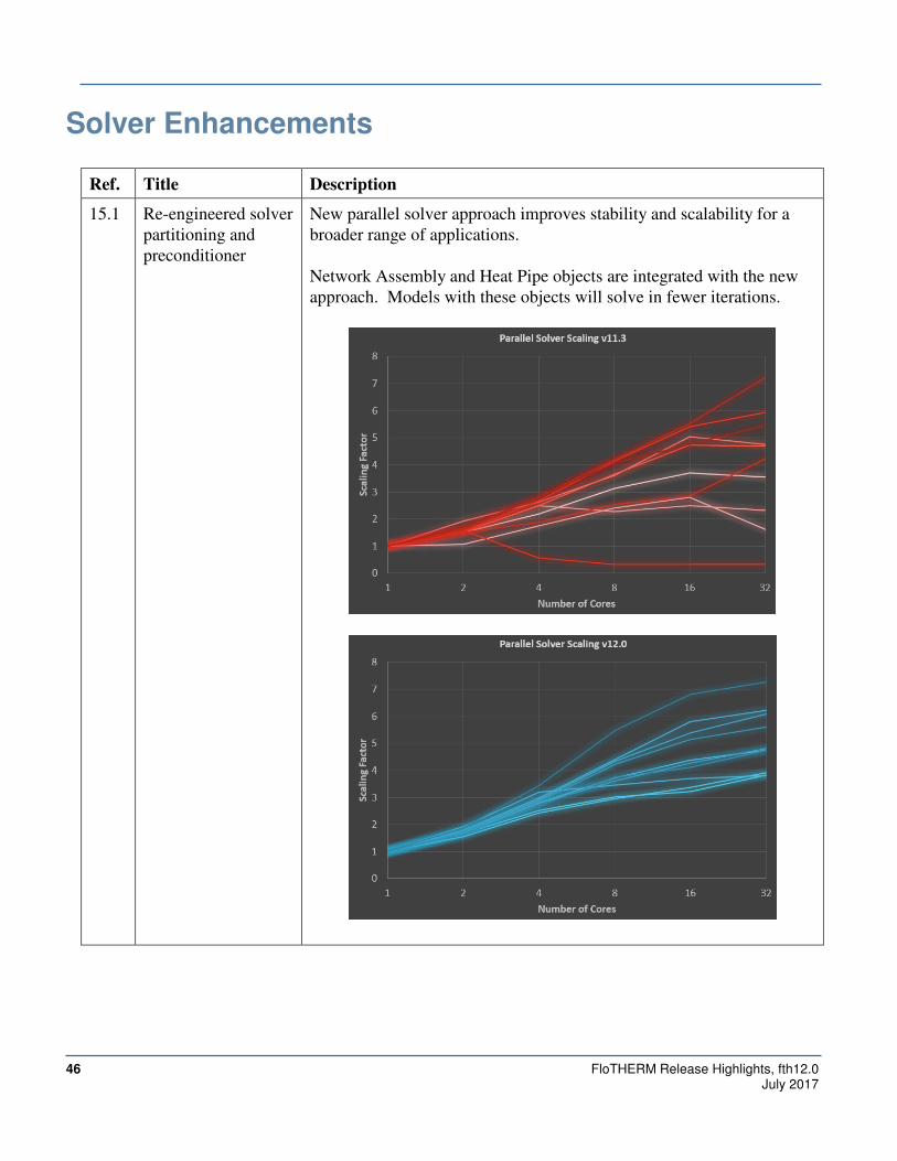
Solver Enhancements
Ref. Title Description
15.1 Re-engineered solver
partitioning and
preconditioner
New parallel solver approach improves stability and scalability for a
broader range of applications.
Network Assembly and Heat Pipe objects are integrated with the new
approach. Models with these objects will solve in fewer iterations.

FloTHERM Release Highlights, fth12.0 47 July 2017
Compact Component
Ref. Title Description
16.1 Localized Grid
interaction
The solver can now support 2-Resistor and Area Array type Compact
Components that abut or intersect a localized grid space. In previous
versions, this situation would have generated an error and denial of
solve.
16.2 Decomposed into a
Network Assembly
Compact Components can be ‘decomposed’ into a Network Assembly.
This can be used to facilitate the process of transforming a steady-state
model into a usable transient model by adding thermal capicitance to
the component.
48 FloTHERM Release Highlights, fth12.0 July 2017
FloMCAD Bridge
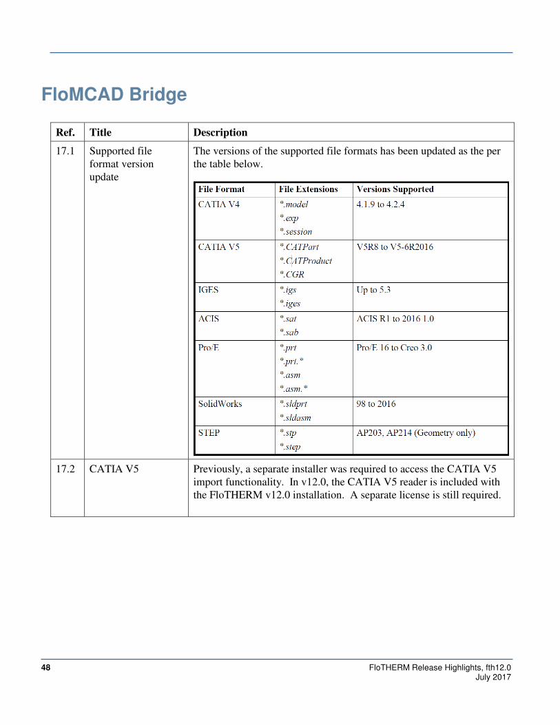
Ref. Title Description
17.1 Supported file
format version
update
The versions of the supported file formats has been updated as the per
the table below.
17.2 CATIA V5 Previously, a separate installer was required to access the CATIA V5
import functionality. In v12.0, the CATIA V5 reader is included with
the FloTHERM v12.0 installation. A separate license is still required.
FloTHERM Release Highlights, fth12.0 49 July 2017
Automation
Ref. Title Description
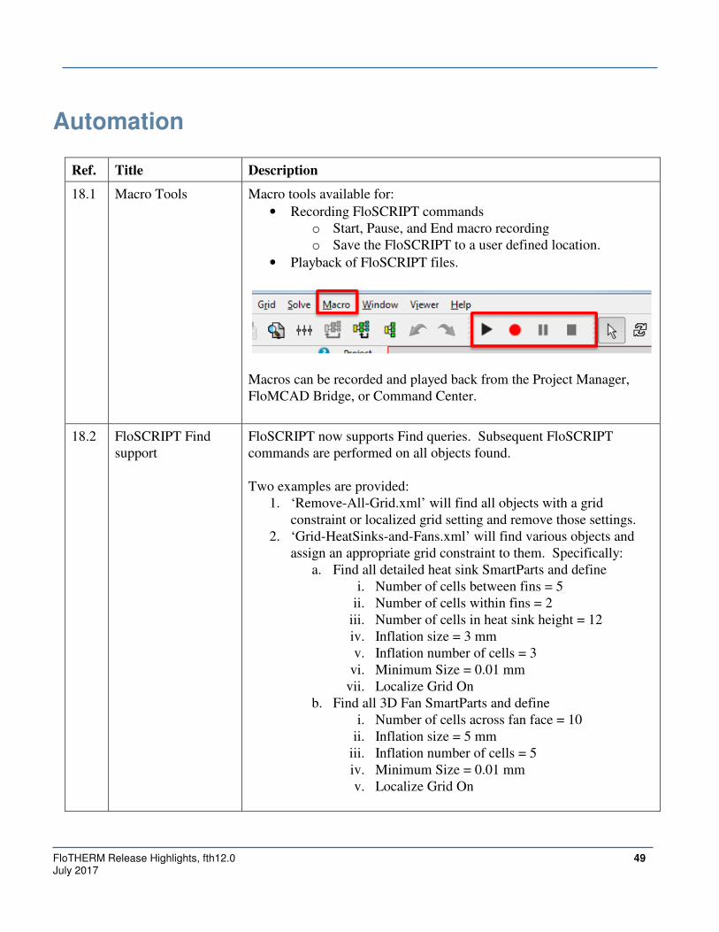
18.1 Macro Tools Macro tools available for:
• Recording FloSCRIPT commands
o Start, Pause, and End macro recording
o Save the FloSCRIPT to a user defined location.
• Playback of FloSCRIPT files.
Macros can be recorded and played back from the Project Manager,
FloMCAD Bridge, or Command Center.
18.2 FloSCRIPT Find
support
FloSCRIPT now supports Find queries. Subsequent FloSCRIPT
commands are performed on all objects found.
Two examples are provided:
1. ‘Remove-All-Grid.xml’ will find all objects with a grid
constraint or localized grid setting and remove those settings.
2. ‘Grid-HeatSinks-and-Fans.xml’ will find various objects and
assign an appropriate grid constraint to them. Specifically:
a. Find all detailed heat sink SmartParts and define
i. Number of cells between fins = 5
ii. Number of cells within fins = 2
iii. Number of cells in heat sink height = 12
iv. Inflation size = 3 mm
v. Inflation number of cells = 3
vi. Minimum Size = 0.01 mm
vii. Localize Grid On
b. Find all 3D Fan SmartParts and define
i. Number of cells across fan face = 10
ii. Inflation size = 5 mm
iii. Inflation number of cells = 5
iv. Minimum Size = 0.01 mm
v. Localize Grid On

50 FloTHERM Release Highlights, fth12.0 July 2017
General
Ref. Title Description
19.1 Multi-Select
Attributes
Multiple attributes can be selected at once in the attribute tree. A
common property sheet can then be used to apply changes to all
selected attributes.
19.2 Find Attributes The Find tool now supports attribute queries and selection.
When attributes are specified as the query target, the Type options will
display the attribute types.
19.3 Summary Columns
for fast attribute
display
Attribute icons displayed in the model summary columns can now be
clicked to have the attribute property sheet displayed.
Objects with multiple attribute attachments of the same type (e.g.,
different grid constraints attached in each direction) repeated clicks on
the icon will cycle through the attached attributes.
19.4 Project Load Speed
Up
The model load process (including import of PDML) has been
streamlined to improve performance. Large models can load up to 70x
faster compared to previous versions.

FloTHERM Release Highlights, fth12.0 51 July 2017
Ref. Title Description
19.5 Updated Thermal
Interface Material
Library
The installed interface material library has been updated to include
recent data and additional vendors.
19.6 Phase Change
Material Library
The installed Material library has been updated to include phase change
materials.
Authorization Codes
If you are updating your software from versions 8.2 – 10.0 to 12.0, no changes to authorization codes
are required for this release. You can retrieve your existing authorization codes by logging on to Licenses
section under My Account on SupportNet.
However if you are updating from any prior versions, new authorization codes are required. The older
authorization codes were generated with the Flomerics license daemon (flomerics). This has changed to the
Mentor Graphics license daemon (mgcld). We have integrated licensing for Mechanical Analysis FloTHERM
product into the standard Mentor Graphics license generator which continues to use FLEXlm, but also uses
functionality provided by MGLS/PCLS software. For further details about new authorization codes, login to
SupportNet and visit http://supportnet.mentor.com/news/Mechanical-Authcodes.cfm.
You may request new authorization codes for FloTHERM by logging in to SupportNet at
http://supportnet.mentor.com and opening a Service Request (remember to choose the "Other Request Type"
radio button, then select "New License Request"), or by contacting your local Mentor Graphics office.
If you wish to continue to use prior releases of FloTHERM, you may continue to use your current flomerics
authorization codes, but please be aware that flomerics authorization codes will not work with the latest
releases.

52 FloTHERM Release Highlights, fth12.0 July 2017
Installation Information For additional information on installation, refer to the FloTHERM_12_0_install.pdf and the help system
within the installation software. You can view this manual in the release_documents directory at the top
level of the CD.
Support Information If you have questions about this software release, please log in to SupportNet. You may search thousands of
technical solutions, view documentation, or open a Service Request online at:
http://supportnet.mentor.com/
If your site is under current support and you do not have a SupportNet login, you may easily register for
SupportNet by filling out the short form at:
http://supportnet.mentor.com/user/register.cfm
All customer support contact information can be found on our web site at:
http://supportnet.mentor.com/contacts/supportcenters/
Supported Configurations
Appendix A: Windows 64 bit
Supported operating systems:
• Windows 10 (Pro and Enterprise editions)
• Windows 8 and 8.1 (Core, Pro and Enterprise editions)
• Windows 7 (Business, Enterprise and Ultimate editions)
• Windows Server 2008 R2, Standard edition
• Windows Server 2012, Standard edition
• Windows Server 2012 R2, Standard Edition

FloTHERM Release Highlights, fth12.0 53 July 2017
Appendix B: Linux, 64 bit
Supported operating systems:
• Red Hat Enterprise Linux 6