Florida Department of Transportation District 6 · Florida Department of Transportation District 6...
216
Request for Proposal SR 836/I-395/I-95 Project December 12, 2016 December 12, 2016 Page 1 of 216 Florida Department of Transportation District 6 DESIGN-BUILD REQUEST FOR PROPOSAL for SR-836/I-395 from West of I-95 to MacArthur Causeway Bridge And I-95 Pavement Reconstruction And I-95 Southbound to SR-836 Westbound And SR-836 from West of NW 17 th Avenue to Midtown Interchange (SR-836/I-395/I-95) Miami-Dade County Financial Projects Number(s): I-395 Reconstruction 251688-1-52-01 (F.A.P. 3951- 501-I), I-95 Pavement Reconstruction 429300-2-52-01 (F.A.P. 0951-685-I), I-95 SB to SR 836 WB Connector 423126-2-52-01, MDX 423126-1-52-01, Miami Dade Water & Sewer 251688-1-56-02 MDX Work Program Number: 83611 Contract Number: E-6J53
Transcript of Florida Department of Transportation District 6 · Florida Department of Transportation District 6...

Request for Proposal
SR 836/I-395/I-95 Project December 12, 2016
December 12, 2016 Page 1 of 216
Florida Department of Transportation
District 6
DESIGN-BUILD
REQUEST FOR PROPOSAL
for
SR-836/I-395 from West of I-95 to
MacArthur Causeway Bridge
And
I-95 Pavement Reconstruction
And
I-95 Southbound to SR-836 Westbound
And
SR-836 from West of NW 17th Avenue to Midtown
Interchange (SR-836/I-395/I-95)
Miami-Dade County
Financial Projects Number(s): I-395 Reconstruction 251688-1-52-01 (F.A.P. 3951-
501-I), I-95 Pavement Reconstruction 429300-2-52-01 (F.A.P. 0951-685-I), I-95 SB to
SR 836 WB Connector 423126-2-52-01, MDX 423126-1-52-01, Miami Dade Water &
Sewer 251688-1-56-02
MDX Work Program Number: 83611
Contract Number: E-6J53

Request for Proposal
SR 836/I-395/I-95 Project December 12, 2016
December 12, 2016 Page 2 of 216
Table of Contents
I. Introduction ........................................................................................................................8
II. Instructions to Proposers ....................................................................................................9 A. Procurement Schedule ......................................................................................... 9 B. Property of the Department .............................................................................. 14 C. Improper Conduct ............................................................................................. 14 D. Federal Funding and Requirements................................................................. 14 E. Procurement Process ......................................................................................... 14
III. Technical Proposal Requirements: ..................................................................................26 A. General: .............................................................................................................. 26 B. Submittal Requirements: .................................................................................. 26 C. Evaluation Criteria: ........................................................................................... 36 D. Proposal Evaluation Criteria and Weighting .................................................. 37 E. Final Selection Process: ..................................................................................... 42 F. Stipend Awards: ................................................................................................. 43
IV. Overview ...........................................................................................................................43 Design-Build Responsibility .............................................................................. 53 Department Responsibility ................................................................................ 55
VI. Threshold Requirements ..................................................................................................55 A. Qualifications ..................................................................................................... 55 B. Joint Venture Firm ............................................................................................ 56 C. Proposal Guaranty ............................................................................................. 56 D. Utility Pre-Proposal Meeting ............................................................................ 57 E. Question and Answer Session ............................................................................ 58 F. Protest Rights ..................................................................................................... 58 H. Non-Responsive Proposals ................................................................................ 59 I. Waiver of Irregularities ..................................................................................... 60 K. Department’s Responsibilities .......................................................................... 60 L. Design-Build Contract Method of Compensation and Funding .................... 61 M. Financial Qualifications and Project Financial Plan (Financial Proposal): . 66
VII. Disadvantaged Business Enterprise (DBE) Program. ....................................................75 A. DBE Availability Goal Percentage: .................................................................. 75 B. DBE Supportive Services Providers: ............................................................... 75 C. Bidders Opportunity List: ................................................................................. 75
VIII. Project Requirements and Provisions for Work. ............................................................76 A. Governing Regulations: ..................................................................................... 76 B. Innovative Aspects: ............................................................................................ 80 C. Geotechnical Services: ....................................................................................... 87 D. Department Commitments: .............................................................................. 87 E. Environmental Permits: .................................................................................... 94 F. Railroad Coordination: ..................................................................................... 98

Request for Proposal
SR 836/I-395/I-95 Project December 12, 2016
December 12, 2016 Page 3 of 216
G. Survey: .............................................................................................................. 100 H. Verification of Existing Conditions: ............................................................... 100 I. Submittals: ........................................................................................................ 101 J. Contract Time: ................................................................................................. 111 K. Project Schedule: ............................................................................................. 111 L. Key Personnel/Staffing: ................................................................................... 114 M. Partner/Teaming Arrangement:..................................................................... 114 N. Meetings and Progress Reporting: ................................................................. 114 O. Public Involvement: ......................................................................................... 115 P. Quality Management Plan (QMP): ................................................................ 116 Q. FHWA Project Management Plan (PMP) ..................................................... 117 R. Liaison Office: .................................................................................................. 117 S. Engineers Field Office: .................................................................................... 117 T. Schedule of Values: .......................................................................................... 118 U. Computer Automation: ................................................................................... 118 V. Construction Engineering and Inspection: .................................................... 119 W. Testing: ............................................................................................................. 119 X. Value Added: .................................................................................................... 119 Y. Adjoining Construction Projects: ................................................................... 120 Z. Issue Escalation: ............................................................................................... 120
IX. Design and Construction Criteria. .................................................................................121 A. General: ............................................................................................................ 121 B. Vibration, Settlement Monitoring and Construction Noise: ........................ 121 C. Geotechnical Services: ..................................................................................... 124 D. Utility Coordination: ....................................................................................... 128 E. Roadway Plans: ................................................................................................ 135 F. Railroad/Transit Accommodations ................................................................ 146 G. Geometric Design:............................................................................................ 147 H. Design Documentation, Calculations, and Computations:........................... 150 I. Structure Plans: ............................................................................................... 150 J. Specifications:................................................................................................... 170 K. Shop Drawings: ................................................................................................ 174 L. Sequence of Construction: .............................................................................. 174 M. Stormwater Pollution Prevention Plans (SWPPP): ...................................... 176 N. Temporary Traffic Control Plan:................................................................... 176 O. Environmental Services/Permits/Mitigation: ................................................ 188 P. Signing and Pavement Marking Plans:.......................................................... 195 Q. Lighting Plans: ................................................................................................. 196 R. Signalization and Intelligent Transportation System Plans: ....................... 200 S. Landscape Architecture: ................................................................................. 206
X. Attachments ....................................................................................................................210
XI. Reference Documents .....................................................................................................213

Request for Proposal
SR 836/I-395/I-95 Project December 12, 2016
December 12, 2016 Page 4 of 216
Definitions:
The following capitalized terms, when used in this Request for Proposal, have the meaning set forth
below:
SR 836 WB Connector means the construction of a SR 9A/I-95 Southbound Ramp to
Westbound SR 836.
Approved Signature Bridge Package means the package which was submitted, passed by the
ARC, and approved by PSC per the requirements of the RFP.
Best Value Proposer (BVP) means the Proposer whose proposal is determined by the PSC to
provide the best value to the Department and MDX.
Business Day means any Calendar day excluding Saturdays, Sundays and Holidays.
Calendar day has the meaning as that term is defined in the Department’s Division I Design-
Build Specifications (Attachment A-02).
Concept Plans means the plans developed to illustrate the work required for the Total Project as
identified in the reference documents: RD-01, RD-0195, and MDXRD-01.
FDOT Contract Bonds means the FDOT Payment Bond and the FDOT Performance Bond, the
forms of which are attached to this RFP as Attachments A-40 and A-41, respectively.
Contract Documents has the meaning as that term is defined in the Department’s Division I
Design-Build Specifications (Attachment A-02).
Department Contract means the contract between the Department and the Design-Build Firm
which requires the Design-Build Firm to construct the Department Project and the MDX Project with
payment to the Design-Build Firm for construction of the Department Project, including payment of
claims for extra work arising from the Department Project. Delay damages on the Total Project will be
paid by the Department and MDX in a proportion to the amounts of the Department Contract and the
MDX Contract as it pertains to the total value of the I-395 Agreements. The amount of the Department
Contract is the total contract amount written out on the Price Proposal if MDWASD accepts the bid for
the MDWASD Work. If MDWASD does not accept the same, then the amount bid for the MDWASD
Work shall be deducted from the total contract amount written out on the Price Proposal to determine the
amount of the Department Contract. The form of the Department Contract is attached to this RFP as A-
44.
Department Commitments means those commitments listed in the PD&E, FEIS/ROD and any
Reevaluations attached as A-08, and those summarized in Section VIII.D of this RFP.
Department Project means the reconstruction of I-395 from the I-95/Midtown Interchange to the
C/L Pier 8 of the MacArthur Causeway Bridge, concrete pavement reconstruction of I-95 from NW 8th
Street to NW 29th Street, and the construction of the SR 836 WB Connector.
Establishment Period means a period of two years after final acceptance of the Department
Contract.

Request for Proposal
SR 836/I-395/I-95 Project December 12, 2016
December 12, 2016 Page 5 of 216
Florida Department of Transportation (Department or FDOT) means the agency created
under Section 20.23, Florida Statutes, and any entity succeeding to the powers, authorities and
responsibilities of the Department invoked by or under the Contract Documents.
Holidays has the meaning as that term is defined in the Department’s Division I Design-Build
Specifications (Attachment A-02).
I-395 Agreements means, collectively, the Department Contract and the MDX Contract.
MDX Contract means the contract between MDX and the Design-Build Firm for construction of
the Total Project, and for payment of construction for the MDX Project, including payment of claims for
extra work arising from the MDX Project. Delay damages on the Total Project will be paid by the
Department and MDX in a proportion to the amounts of the Department Contract and the MDX Contract
as it pertains to the total value of the I-395 Agreements. The form of the MDX Contract is attached to
this RFP as MDXA-17.
MDX Contract Bond means the MDX Design-Build Contract Bond, the form of which is
attached to this RFP as MDXA-18.
MDX Project means the reconstruction of SR 836/I-395 from west of NW 17th Ave. to the I-
95/Midtown Interchange.
Metromover Bridge means the bridge that carries the MDT Metromover that crosses over I-395
approximately 600 feet to the east of the Signature Bridge. Concept Plans have been developed and are
included in RD-01.
Miami-Dade Expressway Authority (MDX) means the expressway authority created by Miami-
Dade County Commission under Section 348.0003, Florida Statutes, and any entity succeeding to the
powers, authorities and responsibilities of MDX invoked by or under the Contract Documents.
Midtown Interchange means the I-395/SR 836/I-95 Interchange.
Price Proposal means the completed Project Specific Price Proposal included in Attachment A-
06, as submitted by the Proposer.
Project Limits means the limits of the Total Project as identified in the Concept Plans.
Proposed Contract Time means the number of Calendar days proposed by Proposer for
completion of the Total Project.
Proposer(s) or Design-Build Firm or Contractor or Bidder means the entities that submit
proposals for the Request for Proposal and also means the entity that executes the I-395 Agreements
solicited through this RFP.
Request for Proposal (RFP) means solicitation of competitive bids and proposals from Design-
Build Firms for separate contracts with the Florida Department of Transportation and the Miami-Dade
Expressway Authority. This definition replaces the definition of Request for Proposal (RFP) in the
Division I Design-Build Specifications (Attachment A-02).
Shared Use Path means the shared use path that is the pedestrian and bicycle bridge and
approaches within the existing right-of-way that will be located over the FECR. The Shared Use Path

Request for Proposal
SR 836/I-395/I-95 Project December 12, 2016
December 12, 2016 Page 6 of 216
shall comply with the FECR Perpetual Aerial Easement Agreement (See Attachment A-16: FECR
Requirements).
Signature Bridge or Signature Span means Bridge Nos. 8/9 of I-395 westbound/eastbound that
will be located over Biscayne Boulevard.
Standard Specifications has the meaning as that term is defined in the Department’s Division I
Design-Build Specifications (Attachment A-02).
Technical Scores means the scores given to the Technical Proposals.
Total Project means, collectively, the Department Project and the MDX Project.
Transition Span means the span that occurs between the approach structures and the west end of
the Signature Bridge superstructure.
Working Day has the meaning as that term is defined in the Department’s Division I Design-
Build Specifications (Attachment A-02).
Abbreviations:
The following abbreviations are used in this Request for Proposal:
AASHTO means American Association of State Highway and Transportation Officials.
AM means Aesthetics Manual.
APTE means Aesthetic Project Technical Enhancement.
ARC means Aesthetic Review Committee.
ATC means Alternative Technical Concept.
CAR means the Department’s Contamination Assessment/Remediation Contractor.
CEI means Construction Engineering and Inspection.
CPM means Critical Path Method.
CSER means Contamination Screening Evaluation Report.
DBE means Disadvantaged Business Enterprise.
F.A.C. means Florida Administrative Code.
FCP means Fracture Control Plan.
FECR means Florida East Coast Railway.
FEIS means Final Environmental Impact Statement.
FHWA means Federal Highway Administration.
FIB means Florida I-Beams.
Request for Proposal
SR 836/I-395/I-95 Project December 12, 2016
December 12, 2016 Page 7 of 216
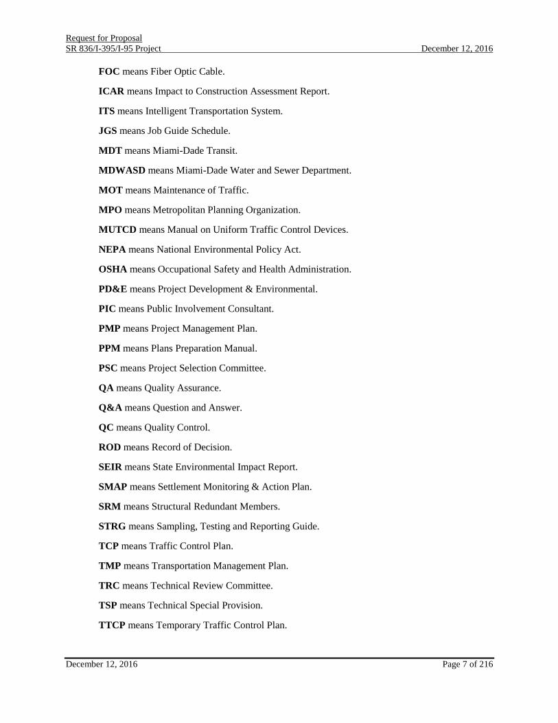
FOC means Fiber Optic Cable.
ICAR means Impact to Construction Assessment Report.
ITS means Intelligent Transportation System.
JGS means Job Guide Schedule.
MDT means Miami-Dade Transit.
MDWASD means Miami-Dade Water and Sewer Department.
MOT means Maintenance of Traffic.
MPO means Metropolitan Planning Organization.
MUTCD means Manual on Uniform Traffic Control Devices.
NEPA means National Environmental Policy Act.
OSHA means Occupational Safety and Health Administration.
PD&E means Project Development & Environmental.
PIC means Public Involvement Consultant.
PMP means Project Management Plan.
PPM means Plans Preparation Manual.
PSC means Project Selection Committee.
QA means Quality Assurance.
Q&A means Question and Answer.
QC means Quality Control.
ROD means Record of Decision.
SEIR means State Environmental Impact Report.
SMAP means Settlement Monitoring & Action Plan.
SRM means Structural Redundant Members.
STRG means Sampling, Testing and Reporting Guide.
TCP means Traffic Control Plan.
TMP means Transportation Management Plan.
TRC means Technical Review Committee.
TSP means Technical Special Provision.
TTCP means Temporary Traffic Control Plan.

Request for Proposal
SR 836/I-395/I-95 Project December 12, 2016
December 12, 2016 Page 8 of 216
UAO or UA/O means Utility Agencies/Owners.
I. Introduction
The Department, pursuant to Section 334.30, Florida Statutes, issues this RFP to solicit competitive bids
and proposals from Design-Build Firms for two separate contracts. The first contract will be the
Department Contract between the Department and the selected Proposer for the design and construction of
the Total Project. The second contract will be the MDX Contract between MDX and the selected Proposer
for the design and construction of the Total Project. The I-395 Agreements consist of the Department
Contract and the MDX Contract. The payments from the Department for the Department Project are
federally funded and which requires the Department Project to be a FHWA Federal-Aid Oversight
construction project.
Contractual Structure
The Department Contract requires the Design-Build Firm to design and construct the Total Project. The
MDX Contract requires the Design-Build Firm to design and construct the Total Project. The MDX
Contract obligates MDX to pay for the cost of the MDX Project. Valid claims for extra work on the
Department Project are solely the responsibility of the Department. Valid claims for extra work on the
MDX Project are solely the responsibility of MDX. Delay damages on the Total Project will be paid by the
Department and MDX in a proportion to the amounts of the Department Contract and the MDX Contract
as it pertains to the total value of the I-395 Agreements.
Order of Precedence
Each of the Contract Documents is an essential part of the Department Contract. The Contract Documents
are intended to be complementary and to be read together as a complete agreement.
In the event of any conflict, ambiguity or inconsistency among the Contract Documents, the order of
precedence shall be as follows:
1. Supplemental Agreements;
2. Alternative Technical Concepts;
3. Request for Proposal;
4. Project Advertisement;
5. Special Provisions;
6. Technical Special Provisions;
7. Plans;
8. Design Standards;
9. Developmental Specifications;
10. Supplemental Specifications;
11. Standard Specifications;
12. Technical and Price Proposals, except Alternative Technical Concepts contained therein;
and
13. Other Contract Documents not listed above.
Notwithstanding the order of precedence among Contract Documents set forth above, in the event of any
conflict, ambiguity or inconsistency between or among any of the provisions in the Contract Documents,

Request for Proposal
SR 836/I-395/I-95 Project December 12, 2016
December 12, 2016 Page 9 of 216
the provisions that use more stringent standards or establish the higher quality, manner or method of
performing the work for the Total Project will prevail. If the Technical Proposal or Proposer’s written
statements or transcripts or minutes of Proposer presentations, includes statements, terms, concepts or
designs that can reasonably be interpreted as offers to provide higher quality items than otherwise required
by the other Contract Documents or to perform services or meet standards in addition to or better than those
otherwise required, then Proposer’s obligations hereunder shall include compliance with all such
statements, terms, concepts and designs. Additional details in a lower priority Contract Document shall be
given effect except to the extent it irreconcilably conflicts with requirements, provisions and practices
contained in the higher priority Contract Document. Computed dimensions govern over scaled dimensions.
II. Instructions to Proposers
The Total Project is being solicited under a single procurement that will result in the award of separate
contracts. It is in the best interest of the Department and MDX to have one Design-Build Firm
simultaneously design and construct the Total Project in order to minimize negative effects of construction
on the traveling public and to maximize any savings of scale. The Instructions to Proposers and other
provisions of the RFP will establish the phases that will be utilized in this procurement to achieve the best
value to the Department and MDX. In case of failure to follow the instructions contained in the RFP, the
Department may determine the Proposer to be deemed non-responsive.
A. Procurement Schedule
The schedule of the events for this procurement process is set forth in the table immediately below. These
dates are subject to change and the Department reserves the right to make changes to the schedule. Notices
of changes (addenda) will be posted on the Department Website at:
http://www.dot.state.fl.us/contractsadministrationdistrict6/Design_Build/DesignBuild.shtm.
It is the responsibility of all potential Proposers to monitor this site for any changing information prior to
submitting your Proposals. Unless otherwise notified in writing by the Department, the dates indicated
below for submission of items or for other actions on the part of a Proposer shall constitute absolute
deadlines for those activities and failure to fully comply by the time stated shall cause a Proposer to be
disqualified.
I-395/I-95/MDX Project Schedule
Dates Event
Tuesday, February 2, 2016 Industry Forum
Wednesday, February 3, 2016 One-on-One Meetings with FDOT and DBF team
(Wednesday)
Monday, February 8, 2016 Advertisement
Monday, March 7, 2016 Letters of Response (LOR) due to District Procurement
Office (5:00PM Local Time)

Request for Proposal
SR 836/I-395/I-95 Project December 12, 2016
December 12, 2016 Page 10 of 216
Monday, April 18, 2016 Public Meeting of Selection Committee to Shortlist (10:00AM
Local Time)
Monday, April 18, 2016 Shortlist Posting (5:00PM Local Time)
Tuesday, April 26, 2016
Meeting with Aesthetic Review Committee, FDOT, and
Shortlisted Teams (One-on-One).
Meeting Duration 90 minutes per team: Day 1
Wednesday, April 27, 2016
Meeting with Aesthetic Review Committee, FDOT, and
Shortlisted Teams (One-on-One).
Meeting Duration 90 minutes per team: Day 2
Wednesday, May 11, 2016 Draft Aesthetic Bridge due to District Procurement Office
(5:00PM Local Time)
Tuesday, May 17, 2016
Meeting No. 1 Vetting ideas meeting for Aesthetic Signature
Bridge Proposal (One-on-One).
Meeting Duration 2 hours per team: Day 1
Wednesday, May 18, 2016
Meeting No. 1 Vetting ideas meeting for Aesthetic Signature
Bridge Proposal (One-on-One).
Meeting Duration 2 hours per team: Day 2
Friday, May 20, 2016
Deadline for Design-Build Firm to request participation in
Alternative Technical Concept/Alternative Project Technical
Enhancement Meeting No. 1 (4:00PM Local Time)
Friday, May 20, 2016
Deadline for Design-Build Firm to submit preliminary list of
Alternative Technical Concept/Alternative Project Technical
Enhancement prior to One-on-One Alternative Technical
Concept/Alternative Project Technical Enhancement Meeting
No. 1 (4:00PM Local Time)
Tuesday, May 24, 2016
Alternative Technical Concept/Alternative Project Technical
Enhancement Meeting No. 1:
Meeting Duration: 4 hours per team: Day 1
Wednesday, May 25, 2016
Alternative Technical Concept/Alternative Project Technical
Enhancement Meeting No. 1:
Meeting Duration: 4 hours per team: Day 2
Thursday, May 26, 2016
Alternative Technical Concept/Alternative Project Technical
Enhancement Meeting No. 1:
Meeting Duration: 4 hours per team. Day 3
Wednesday, June 1, 2016
Meeting No. 2 Vetting ideas meeting for Aesthetic Signature
Bridge Proposal (One-on-One).
Duration 2 hours per team: Day 1
Thursday, June 2, 2016
Meeting No. 2 Vetting ideas meeting for Aesthetic Signature
Bridge Proposal (One-on-One).
Duration 2 hours per team: Day 2
Thursday, June 23, 2016 Final Aesthetic (Signature) Bridge due to District
Procurement Office (5:00PM Local Time)

Request for Proposal
SR 836/I-395/I-95 Project December 12, 2016
December 12, 2016 Page 11 of 216
Tuesday, August 2, 2016
Alternative Technical Concept/Alternative Project Technical
Enhancement Meeting No. 1A (Optional): Meeting Duration:
2 hours per team: Day 1
Wednesday, August 3, 2016
Alternative Technical Concept/Alternative Project Technical
Enhancement Meeting No. 1A (Optional): Meeting Duration:
2 hours per team: Day 2
Friday, August 19, 2016
Project Selection Committee Public Meeting determining the
Pass/Fail results of the Aesthetic Signature Bridge Proposal
(10:00AM Local Time)
Wednesday, August 24, 2016
Deadline for Design-Build Firm to request participation in
Alternative Technical Concept/Alternative Project Technical
Enhancement Meeting No. 2 (4:00PM Local Time)
Wednesday, August 24, 2016
Deadline for Design-Build Firm to submit preliminary list of
Alternative Technical Concept/Alternative Project Technical
Enhancement prior to One-on-One Alternative Technical
Concept/Alternative Project Technical Enhancement Meeting
No. 2 (4:00PM Local Time)
Tuesday, August 30, 2016 Alternative Technical Concept/Alternative Project Technical
Enhancement Meeting No. 2: Duration 4 hours per team: Day 1
Wednesday, August 31, 2016 Alternative Technical Concept/Alternative Project Technical
Enhancement Meeting No. 2: Duration 4 hours per team: Day 2
Thursday, September 1, 2016 Alternative Technical Concept/Alternative Project Technical
Enhancement Meeting No. 2: Duration 4 hours per team: Day 3
Wednesday, September 28, 2016 Utility Pre-Proposal Meeting facilitated by the District Utilities
Administrator (3 Days September 28 through September 30)
Friday, September 30, 2016
Deadline for Design-Build Firm to request participation in
Alternative Technical Concept/Alternative Project Technical
Enhancement Meeting No. 3 (4:00PM Local Time)
Friday, September 30, 2016
Deadline for Design-Build Firm to submit preliminary list of
Alternative Technical Concept/Alternative Project Technical
Enhancement prior to One-on-One Alternative Technical
Concept/Alternative Project Technical Enhancement Meeting
No. 3 (4:00PM Local Time)
Monday, October 10, 2016
Alternative Technical Concept/Alternative Project Technical
Enhancement Meeting No. 3:
Duration 3.5 hours per team: Day 1
Tuesday, October 11, 2016
Alternative Technical Concept/Alternative Project Technical
Enhancement Meeting No. 3:
Duration 3.5 hours per team: Day 2
Wednesday, October 12, 2016
Alternative Technical Concept/Alternative Project Technical
Enhancement Meeting No. 3:
Duration 3.5 hours per team: Day 3
Monday, October 31, 2016 Deadline submission of all Draft ATCs.

Request for Proposal
SR 836/I-395/I-95 Project December 12, 2016
December 12, 2016 Page 12 of 216
Tuesday, November 1, 2016
Deadline for Design-Build Firm to request participation in
Alternative Technical Concept/Alternative Project Technical
Enhancement Meeting No. 4 (4:00PM Local Time)
Tuesday, November 1, 2016
Deadline for Design-Build Firm to submit preliminary list of
Alternative Technical Concept/Alternative Project Technical
Enhancement prior to One-on-One Meeting Alternative
Technical Concept/Alternative Project Technical Enhancement
Meeting No. 4 (4:00PM Local Time)
Tuesday, November 8, 2016
Alternative Technical Concept/Alternative Project Technical
Enhancement Meeting No. 4: This Alternative Technical
Concept/Alternative Project Technical Enhancement meeting is
for continuing discussion of only ATC/APTE that were
previously submitted as draft ATC/APTE submittals.
Duration 3.5 hour per team: Day 1
Wednesday, November 9, 2016
Alternative Technical Concept/Alternative Project Technical
Enhancement Meeting No. 4: This Alternative Technical
Concept/Alternative Project Technical Enhancement meeting is
for continuing discussion of only ATC/APTE that were
previously submitted as draft ATC/APTE submittals.
Duration 3.5 hour per team: Day 2
Thursday, November 10, 2016
Alternative Technical Concept/Alternative Project Technical
Enhancement Meeting No. 4: This Alternative Technical
Concept/Alternative Project Technical Enhancement meeting is
for continuing discussion of only ATC/APTE that were
previously submitted as draft ATC/APTE submittals.
Duration 3.5 hour per team: Day 3
Tuesday, December 6, 2016
Alternative Technical Concept Meeting No. 5: This Alternative
Technical Concept meeting is exclusively for the I-95
pavement design and the minimum width of lanes in direct
response to Addendum 11.
Duration 1 hour per team: Day 1
Tuesday, December 13, 2016
Deadline for Design-Build Firm to submit all draft ATC
submittals that are exclusively for the I-95 pavement design
and the minimum width of lanes in direct response to
Addendum 11.
Friday, December 16, 2016
Deadline for Design-Build Firm to submit all final ATC/APTE
submittals except those for the I-95 pavement design and the
minimum width of lanes in direct response to Addendum 11.
As a precondition to submitting a final ATC/APTE submittal,
the Design-Build Firm must have previously submitted the
ATC as a draft ATC submittal and discussed such draft ATC
submittal with FDOT at a scheduled One-on-One ATC
Meeting. (5:00PM Local Time)

Request for Proposal
SR 836/I-395/I-95 Project December 12, 2016
December 12, 2016 Page 13 of 216
Wednesday, December 21, 2016
Deadline for Design-Build Firm to submit all final ATCs that
are exclusively for the I-95 pavement design and the minimum
width of lanes in direct response to Addendum 11. As a
precondition to submitting this final ATC submittal, the
Design-Build Firm must have previously submitted the ATC as
a draft ATC submittal and discussed such draft ATC submittal
with FDOT at a scheduled One-on-One ATC Meeting.
(5:00PM Local Time)
Tuesday, January 17, 2017
Deadline for the Department to provide Design Build Team
with approved Alternative Technical Concept/Alternative
Project Technical Enhancement.
Tuesday, January 24, 2017
Deadline for submittal of questions, for which a response is
assured, prior to the submission of Technical Proposal. All
questions shall be submitted to the Pre-Bid Q&A website.
(5:00PM Local Time)
Tuesday, February 7, 2017
Deadline for the Department to post responses to the Pre-Bid
Question and Answers website for questions submitted by the
Design-Build Firms prior to the submittal of the Technical
Proposal. (5:00PM Local Time)
Tuesday, February 14, 2017 Technical Proposals due in District Procurement Office
(5:00PM Local Time)
Wednesday, March 15, 2017
Question and Answer Session. Times will be assigned during
the pre-proposal meeting. One hour will be allotted for
questions and responses.
Wednesday, March 22, 2017
Deadline for Design-Build Firms to submittal of Written
Clarification letter following Question and Answer Session
(4:00PM Local Time)
Monday, March 27, 2017
Deadline for Design-Build Firms to submit questions to the
Pre-Bid Q&A website (for which an answer is assured) in
accordance with Specification 2-4 prior to the submittal of the
Bid Price Proposal (5:00PM Local Time)
Monday, April 3, 2017
Deadline for the Department to post responses to the Pre-Bid
Q&A website for questions submitted by the Design-Build
Firms for Bid Price Proposal
Friday, April 7, 2017
Deadline for Design-Build Firm to submit Written
Confirmation letter stating that they intend to comply with all
the requirements in the Contract Document (4:00 PM Local
Time)
Friday, April 7, 2017
Technical Scores due from Technical Review Committee and
Aesthetic Review Committee (5:00PM
Local Time)
Monday, April 10, 2017 Price Proposals and Financial Plans due to District
Procurement Office (10:00AM Local Time)
Monday, April 10, 2017
Public Meeting announcing of Technical Scores and opening
of Price Proposals and Financial Proposals Posting of intended
decision (11:00AM Local Time)
Request for Proposal
SR 836/I-395/I-95 Project December 12, 2016
December 12, 2016 Page 14 of 216
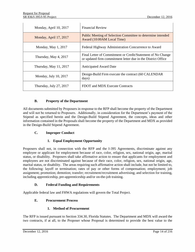
Monday, April 10, 2017 Financial Review
Monday, April 17, 2017 Public Meeting of Selection Committee to determine intended
Award (10:00AM Local Time)
Monday, May 1, 2017 Federal Highway Administration Concurrence to Award
Thursday, May 4, 2017 Final Letter of Commitment or Credit/Statement of No Change
or updated firm commitment letter due in the District Office
Thursday, May 11, 2017 Anticipated Award Date
Monday, July 10, 2017 Design-Build Firm execute the contract (60 CALENDAR
days)
Thursday, July 27, 2017 FDOT and MDX Execute Contracts
B. Property of the Department
All documents submitted by Proposers in response to the RFP shall become the property of the Department
and will not be returned to Proposers. Additionally, in consideration for the Department’s payment of the
Stipend as specified herein and the Design-Build Stipend Agreement, the concepts, ideas and other
information contained in the Proposals shall become the property of the Department and MDX as provided
in the Design-Build Stipend Agreement.
C. Improper Conduct
1. Equal Employment Opportunity
Proposers shall not, in connection with the RFP and the I-395 Agreements, discriminate against any
employee or applicant for employment because of race, color, religion, sex, national origin, age, marital
status, or disability. Proposers shall take affirmative action to ensure that applicants for employment and
employees are not discriminated against because of their race, color, religion, sex, national origin, age,
marital status, or disability. The areas requiring such affirmative action shall include, but not be limited to,
the following: layoff or termination; rates of pay or other forms of compensation; employment; job
assignment; promotion; demotion; transfer; recruitment/recruitment advertising; and selection for training,
including apprenticeship, pre-apprenticeship and/or on-the-job training.
D. Federal Funding and Requirements
Applicable federal law and FHWA regulations will govern the Total Project.
E. Procurement Process
1. Method of Procurement
The RFP is issued pursuant to Section 334.30, Florida Statutes. The Department and MDX will award the
two contracts, if at all, to the Proposer whose Proposal is determined to provide the best value to the

Request for Proposal
SR 836/I-395/I-95 Project December 12, 2016
December 12, 2016 Page 15 of 216
Department and MDX. Evaluation of Proposals will be based on information submitted in responsive
Proposals or otherwise available to the Department, and will involve an evaluation of technical and aesthetic
criteria, as further detailed in the RFP.
The Proposals will be evaluated by the following:
PSC shall select the BVP for the Total Project.
TRC to review and score the Aesthetic Volume and Technical Volume of the Technical
Proposal.
ARC to pass/fail the Aesthetic Signature Bridge Proposal options. For informational purposes
only, the individual members of the ARC will provide a ranking for each of the Aesthetic
Signature Bridge Proposal options for each Proposer.
ARC will review and score the Aesthetic Volume of the Technical Proposal.
The Department’s Project Finance Manager to pass/fail the financial aspects of the Financial
Proposal.
The procurement for the Total Project will take place in four phases:
Phase I: Short Listing
Phase II: Aesthetic Signature Bridge Submission Pass/Fail
Phase III: Technical Proposal: Technical and Aesthetic Volumes Submissions and Scoring
Phase IV: Price Proposal and Financial Proposal Submittals
Communications between the Department and Proposers during Procurement
The Department will send all Proposers a copy of the RFP, including Addenda, and other Project-related
documents and materials in electronic format at no cost.
The Department Designated Point of Contact:
The Department has designated the following individual to be its Procurement Officer:
Nadine Chinapoo
Procurement Services District 6
Florida Department of Transportation
E-mail address: [email protected]
From time to time during the procurement process of the Total Project or during the term of the I-395
Agreements, the Department may designate another Procurement Officer or other Department
representatives to carry out some or all of the Department’s obligations pertaining to the Total Project.
Rules of Contact
Proposers or persons acting on their behalf may not contact, between the Project Advertisement and the end
of the 72-hour period following the agency posting the notice of intended award, excluding Saturdays,
Sundays, and state holidays, any employee or officer of the executive or legislative branch or any employee
or officer or member of MDX or any employee or officer or member of MDT or any individual identified
in Attachment A-34 concerning any aspect of the RFP, except in writing to the Procurement Officer or as
provided in the RFP. Violation of this provision may be grounds for rejecting Proposals. In order to ensure
Request for Proposal
SR 836/I-395/I-95 Project December 12, 2016
December 12, 2016 Page 16 of 216
a fair, competitive, and open process, once the Total Project is advertised, all communications between
Proposers and the Department or MDX or MDT must be directed to the Department's Prebid Question and
Answer website. It is the responsibility of the Proposer to review the Prebid Question and Answer website
and the Project Advertisement for updates prior to the Letters of Response deadline.
Unless specifically authorized elsewhere in this RFP, the Procurement Officer, or another Department
representative designated in writing by the Procurement Officer, is the Department's single contact and
source of information for this procurement.
The rules of contact set forth in this Section shall apply during the Project procurement process. These
rules are designed to promote a fair, unbiased, and legally defensible procurement process. Contact
includes face-to-face, telephone, electronic-mail (e-mail) or formal written communication.
The specific rules of contact are as follows:
A) Unless otherwise specifically noted in this RFP or authorized by the Procurement Officer, all
Proposer communication with the Department will be between the Proposer’s identified
representatives and the Procurement Officer. All such communication must be in writing (by
mail or e-mail).
B) Under normal circumstances, the Procurement Officer will contact a Proposer in writing through
the Proposer's designated representative.
C) Commencing with the issuance of this RFP and continuing until the earliest of (1) execution
and delivery of the I-395 Agreements, (2) the Department’s rejection of all Proposals or (3)
cancellation of the Total Project procurement, neither a Proposer nor its agents may have ex
parte communications with State officials, the Department employees, members of the Project
Selection Committee, the advisory scoring committees, any other person who will evaluate
Proposals and any person identified in Attachment A-34 regarding the Project, except for
communications expressly permitted in this RFP or through the process identified above. The
foregoing restriction shall not, however, preclude or restrict communications regarding matters
unrelated to the Total Project or from participating in public meetings or any public or Proposer
workshop related to the Total Project.
D) Any contact by a Proposer determined to be improper or prohibited may result in
disqualification of the Proposer.
E) The Department will disseminate written communications regarding the Total Project from the
Department on the Department letterhead. The Procurement Officer will sign such
communications. Alternatively, the Procurement Officer may communicate via email
originating from the Department’s server.
F) The Department will not be responsible for or bound by (1) any oral communication or (2) any
other information or contact that occurs outside the official communication process specified
herein, unless confirmed in writing by the Procurement Officer.
Language and United States Dollar Requirements
All correspondence regarding the RFP, Proposal, and I-395 Agreements is to be in the English language.
If any original documents required for the Proposal, except in pre-printed or reference materials, are in any

Request for Proposal
SR 836/I-395/I-95 Project December 12, 2016
December 12, 2016 Page 17 of 216
other language, the Proposer shall provide an English translation, certified by an individual authorized as a
translator by one of the Circuit Courts of the State, which shall take precedence in the event of conflict with
the original language. The Proposer shall exclusively use inflated United States dollars in its Proposal. In
the evaluation of Proposals, the Department may choose to disregard any financial figures provided by the
Proposer in denominations other than United States dollars.
Questions and Responses Regarding the RFP
Proposers shall be responsible for reviewing the RFP and any Addenda issued by the Department prior to
the Technical Proposal Due Date, and for requesting written clarification or interpretation of any perceived
discrepancy, deficiency, ambiguity, error or omission contained therein, or of any provision which the
Proposer fails to understand. Proposers shall submit, and the Department will respond to, such requests in
accordance with this RFP. Proposers shall direct all questions to the Departments Question and Answer
website:
https://www3b.dot.state.fl.us/BidQuestionsAndAnswers/Proposal.aspx/SearchProposal
Timing of Requests
Proposers must submit any requests under this RFP prior to the deadline for such requests in this RFP. The
Department does not commit to answer any questions submitted by the Proposers after this deadline.
Addenda
The Department may, by issuing an addendum, modify conditions or requirements of the RFP at any time
after its formal issuance.
Examination of the Request for Proposals Package and Work Site
Proposers are expected to carefully examine the project site and the complete RFP package, including
Reference Documents, before submitting a Proposal.
Each Proposer shall, by submission of a Proposal, be deemed to have made such examination and to have
satisfied itself as to the conditions to be encountered in performing the work on the Total Project.
2. Short List
In order to be considered as a short list candidate, a Proposer must submit to the Department a Letter of
Response. Staff will develop a written analysis of the submitted Letter of Response and provide the analysis
to each member of the PSC.
The Letter of Response package shall include only photos of substantially completed projects/structures
in which the Proposer has been involved; digital images or sketches of proposed bridge structure(s) or
proposed streetscape for the Total Project shall not be included in the Letter of Response. Proposers must
identify which entity of the team was involved in the bridge/structure and the type of procurement, such
as design-bid-build, design-build, P3 public private partnership. The Department may determine a Letter
of Response to be deemed non-responsive if it includes such images, sketches or streetscape.
The Letter of Response is limited to fifteen (15) pages of 8 1/2” x 11’ in size, not including resumes,
affidavit from bonding company, and letter from Chief Financial Officer(s)/Treasurer(s). All font
(including in graphics, tables, and captions on photos) must be standard Arial Narrow, 11 point, single

Request for Proposal
SR 836/I-395/I-95 Project December 12, 2016
December 12, 2016 Page 18 of 216
line spacing with no modification of font or spacing allowed. ½” clear margin on all sides must be
maintained on all pages. Character styling such as use of color, bold, and italics are allowed. Use of a
table is recommended for text boxes.
Provide in the Letter of Response one (1) page resumes for each of the following sixteen (16) key staff
positions, as applicable:
a. Construction Project Manager;
b. Construction Design-Build Coordinator;
c. Construction Roadway Superintendent;
d. Construction Structures Superintendent (segmental bridge);
e. Construction Structures Superintendent (steel bridge);
f. Construction Structures Superintendent (Signature Bridge);
g. Design Project Manager;
h. Design Roadway Engineer of Record;
i. Design Structures Engineer of Record (non-Signature Bridge);
j. Design Structures Engineer of Record (Signature Bridge);
k. Contractor's Engineer of Record (Signature Bridge);
l. Design Engineer of Record (segmental bridge);
m. Design Engineer of Record (steel bridge);
n. Individuals Performing Aeroelastic Model Testing;
o. Signature Bridge architect; and
p. Licensed Landscape Architect or urban designer.
In addition to the above sixteen (16) resumes, the Design-Build Firm may submit five (5) additional
resumes for additional personnel to be evaluated.
By submittal of the Letter of Response the Proposer certifies that all information provided in the Letter of
Response is true and accurate. The Proposer further affirms that the individuals proposed as staff are
currently employed by the firm(s) identified, or the Proposer has provided a statement of when the
individual will become employed by the identified firm(s).
Fifteen (15) copies of the Letters of Response and two (2) CD’s for the Letters of Response shall be
delivered by the submission deadline on the Letters of Response Due Date to:
Nadine Chinapoo
Procurement Office, District 6
1000 NW 111th Ave., Room #6202
Miami, FL 33172
Acknowledgement of receipt of the Letter of Response will be evidenced by the issuance of a receipt by a
member of the Department staff. The Department will not accept facsimile or other electronically submitted
Letters of Response.
The Department will not accept any Letter of Response delivered after the Letters of Response Due Date.
Proposers are solely responsible for ensuring that the Department receives their Letter of Response by the
Letters of Response Due Date at the address listed above. The Department shall not be responsible for any
delays in delivery caused by weather, difficulties experienced by couriers or delivery services, misrouting
of packages by courier or delivery services, improper, incorrect or incomplete addressing of deliveries, and

Request for Proposal
SR 836/I-395/I-95 Project December 12, 2016
December 12, 2016 Page 19 of 216
other occurrences beyond the control of the Department.
Contractors who are members of the Design-Build Firm and the lead design Consultant of the Design-Build
Firm shall not team with other Proposers to submit more than one Technical Proposal in response to this
RFP. The Design-Build Firm or proposed key staff of the Design-Build Firm shall not be changed after
submittal of the Letter of Response without written consent of the Department. Failure to receive approval
on such a change may result in the Technical Proposal being declared non-responsive.
The PSC will evaluate each submission based on the following criteria:
a. Approach to projects:
Understanding of the critical project issues;
Approach to critical project issues; and
Summarize Proposer’s strategy for ensuring quality.
b. Design Experience in the last fifteen (15) years on Similar projects with:
High level of aesthetics (Level 3 in accordance with the PPM);
Structures in dense urban environment; and
Suspender/Cable support main spans of at least 550-ft. in length.
c. Construction Experience in the last fifteen (15) years on Similar projects with:
High level of aesthetics (Level 3 in accordance with the PPM);
Construction in dense urban environment; and
Suspender/Cable support main spans of at least 550-ft. in length.
d. For each project referenced under b. or c. above the Design-Build Firm shall include:
a) Starting date
b) Completion date or anticipated completion date
c) Budget
d) Owner performance evaluation (if available)
e) References
f) Points of contact
g) Telephone numbers of Owner
h) Safety record
i) Time delays
j) Incidents of litigation/disputes history
k) Current Safety Modifier Index and OSHA violations within the last five (5) years.
e. Resumes of Key Staff.
f. An affidavit from a bonding company that certifies the Design-Build Firm has the financial means
and capacity to bond 100% payment and performance for the face amount of $616,139,180 for the
Department Project and for the face amount of $186,000,000 for the MDX Project.
g. Letter from the Chief Financial Officer or treasurer of the Design-Build Firm or any partners of the
Design-Build Firm that speaks to the Design-Build Firm’s ability to obtain financing for the Total
Project and any material financial matters that may affect the ability to obtain financing.

Request for Proposal
SR 836/I-395/I-95 Project December 12, 2016
December 12, 2016 Page 20 of 216
A public meeting will be held for the final analysis and selection of the teams that have the highest
likelihood of being selected the BVP.
3. Aesthetic Signature Bridge Proposals Pass/Fail
Each shortlisted firm will be given the option to submit draft Aesthetic Signature Bridge Proposals, pursuant
to the Procurement Schedule, for review and comment by Department Staff, prior to final submission of
Aesthetic Signature Bridge Proposals for ARC evaluation. Each shortlisted firm may submit up to three
(3) Aesthetic Signature Bridge Proposals for evaluation by the ARC. Each ARC member will independently
pass or fail each option submitted. Each ARC member will also rank the options provided by a Proposer
against the other options provided by the same Proposer. An example of the pass-fail/ranking sheet that
will be provided to the ARC members is provided as a reference document, RD-08, to this RFP.
Although the ARC members will rank the different options against the other options provided by a Proposer,
these rankings are purely for informational purposes only, and will have no direct impact on the Pass/Fail
decision or on the evaluation of the Proposer’s Technical Proposal.
In a public meeting, as outlined on the Procurement Schedule, the pass/fail results will be opened and
confirmed by the PSC. In order for an option to be “passed,” it must receive four (4) out of five (5) “passes”
from the ARC members.
If after all the options from all the Proposers have been scored, less than three (3) teams have received an
option that “passed,” the PSC will recalculate the options based on “passing” being lowered to three (3) out
of five (5) passes from the ARC members.
Proposers must receive at least one “pass” rating on at least one option to advance to Phase III of the
procurement. Each Proposer that receives more than one (1) “passing” option must choose one of the
“passed” options to incorporate in the Technical Proposals in Phase III of the procurement.
Aesthetic Signature Bridge Proposals and Draft Aesthetic Signature Bridge Proposals shall be delivered by
the submission deadline on the Procurement Schedule to:
Nadine Chinapoo
Procurement Office, District 6
1000 NW 111th Ave, Room #6202
Miami, FL 33172
Acknowledgement of receipt of the Aesthetic Signature Bridge Proposals and Draft Aesthetic Signature
Bridge Proposals will be evidenced by the issuance of a receipt by a member of the Department staff. The
Department will not accept facsimile or other electronically submitted Aesthetic Signature Bridge Proposals
or Draft Aesthetic Signature Bridge Proposals.
The Department will not accept any Aesthetic Signature Bridge Proposals and/or Draft Aesthetic Signature
Bridge Proposals delivered after the Aesthetic Signature Bridge Proposal Due Date. Proposers are solely
responsible for ensuring that the Department receives their Proposals by the Aesthetic Signature Bridge
Proposal Due Date at the address listed above. The two submissions of the Draft Aesthetic Signature Bridge
Proposals must be made to the Department by the date listed in the Procurement Schedule. The Department
shall not be responsible for any delays in delivery caused by weather, difficulties experienced by couriers
or delivery services, misrouting of packages by courier or delivery services, improper, incorrect or
incomplete addressing of deliveries, and other occurrences beyond the control of the Department.

Request for Proposal
SR 836/I-395/I-95 Project December 12, 2016
December 12, 2016 Page 21 of 216
Vetting Meeting for the Aesthetic Signature Bridge Proposals
The Department will meet with each Proposer twice to discuss the submitted Draft Aesthetic Signature
Bridge Proposals as outlined below. These meetings will be held in order to discuss any concerns the
Proposers and/or the Department may have about the Proposers Draft Aesthetic Signature Bridge Proposals.
For these vetting meetings only, there is no limit to number of Signature Bridge Options that may be
submitted. No decisions will be made by the Department concerning ATCs, or other binding approvals, and
no member of the PSC, TRC, or the ARC will attend the Vetting Meetings. The meetings are solely to
have an open discussion with the Department concerning its understanding and completeness of the Draft
Aesthetic Signature Bridge Proposals prior to the Proposers Final Submission of the Aesthetic Signature
Bridge Proposal. If a Proposers Aesthetic Signature Bridge Proposal is such that it will require an ATC to
be approved in order for it to be in compliance with the RFP, the Proposer may still submit the Aesthetic
Signature Bridge Proposal for evaluation, but the Department makes no commitment through the Vetting
Meeting or any other correspondence that the ATC will be approved. A Passing Score by the ARC does
not relieve the Proposer from seeking approval for any ATCs that may be required due to the design.
Aesthetic Signature Bridge Proposal Requirements
The following requirements shall be used for the submission of the Aesthetic Signature Bridge(s) from
each Proposer. There are two submissions for this phase of Procurement – Draft and Final Submittals.
The items described below that are applicable at each submittal are denoted after each bullet with a (D)
for Draft and/or an (F) for Final. Only items listed below as an (F) label will be permitted to be included
in the Final Submittal to the Aesthetic Review Committee, any extra information will be removed prior to
the packet being delivered to the ARC, and such a submittal may cause the Proposer to be held non-
responsive.
Separate each proposed Signature Bridge Option and label Option A, B, C in accordance with the
requirements described herein. The 11” x 17” submittal shall be bound separately from the 24” x
26” submittal. (F)
For each proposed Signature Bridge Option: Reference any requirements of the RFP which are
inconsistent with the proposed Signature Bridge Option, include an explanation of the nature of
the deviations from the requirements along with suggested changes to the requirements of the
RFP which would allow the Signature Bridge Option. (D)
See Attachment A-35 for preset backgrounds and camera view coordinates used to develop the
preset background views. (D) and (F)
For each proposed Signature Bridge Option, provide one 24” x 36” color composite rendering
package as described below (D) and (F):
o A minimum of fourteen (14) renderings are required for each Signature Bridge Option as
defined below. Three (3) additional team renderings per proposed Signature Bridge
Option are permitted as long as they are captured from a point of view that is a real
photograph that is taken at the site. The additional team renderings may be a night or day
time depiction at the discretion of the Proposer but the background must be obtained from
a photograph captured on site. These team renderings must be labeled as “Team
Templates.”

Request for Proposal
SR 836/I-395/I-95 Project December 12, 2016
December 12, 2016 Page 22 of 216
o Each rendering in the package shall include the Proposer name, the Signature Bridge
Option and all Team Templates. All non-Team Templates shall include the
corresponding template name in Attachment A-35. For all nighttime renderings add only
the baseline Signature Structure Aesthetic Lighting as defined in Section 6.5.3.1 of the
Aesthetics Manual (Attachment A-18). All nighttime renderings shall only include white
light.
o For templates 1 thru 5 and template 8, the composite renderings shall be made up of the
digital 3-D model of the proposed Signature Bridge Option and the preset background
that is provided. This includes both day and night views. The templates provided by the
Department shall not be re-sized or cropped.
o For Templates 6 and 7:
Provide daytime renderings for each template consisting of the digital 3-D model
of the proposed Signature Bridge without a background. Show the ground
surfaces and roadway surfaces under the bridge, however, do not show any
background components, underdeck features, streetscape, landscape, figures,
vehicles, or entourage features in the rendered image beyond what is given in the
preset backgrounds.
Position Camera under the proposed Signature Bridge Span(s) and locate 6 ft.
above the proposed ground surface looking west such that both the bottom side
of the Signature Bridge, and Transition Span is visible. Also, position camera
view so that the western most Signature Substructure Element(s) are visible.
o 11” x 17” composite renderings shall not be submitted.
o Include Signature Bridge and adjacent Transition Span surface textures, colors, and
shading. Any underdeck features, streetscape, landscape, or figures beyond what is given
in the preset background image are strictly prohibited. The renderings may include the
approach spans (portion of bridge viaduct beyond Signature Bridge Spans and Transition
Spans), however these portions should be grayed-out (light gray for daytime renderings
and dark gray for nighttime renderings) and will not be considered part of the submission. o Do not add the Metromover to any of the renderings. Also, do not modify the
Metromover Bridge shown in Template 5. o The 3D model for both the Signature Bridge Spans and Transition Span shall illustrate
the following bridge components:
All load carrying member sizes, and shapes,
Configuration of all load carrying member,
Suspender/Cable/stay arrangement and pattern,
Surface colors and textures,
Templates 1 through 8 shall only use white lights for the night views. For the
three (3) additional Team Templates, colored lighting may be shown consistent
with the performance of the fixtures being provided.
Design-Build Firms to provide for each proposed Signature Bridge Option a Bridge Typical
Section (11” x 17”) Plan Sheet(s) at the maximum bridge height location in accordance with
Chapter 17 of the Structures Detailing Manual, including the plan sheet border. The Bridge
Typical Section shall include the full cross section including pylons, arches, cable/stays, bridge
deck, deck support system, lane configuration, etc. Two (2) sheets maximum. Do not include
renderings. (D) and (F)
Design-Build Firms to provide for each proposed Signature Bridge Option a General Plan and
Elevation (11” x 17”) Plan Sheet(s) of the Signature Bridge and adjacent Transition Span located

Request for Proposal
SR 836/I-395/I-95 Project December 12, 2016
December 12, 2016 Page 23 of 216
west of the Signature Bridge in accordance with Chapter 7 of the Structures Detailing Manual,
including the plan sheet border. Two (2) sheets maximum. The General Plan & Elevation Sheet
shall include: (D) and (F)
o All major load carrying members shapes and configurations,
o Cable/stay number, arrangement and pattern,
o Elevation of Apex height,
o Elevation of highest cable attachment to pylon or arch,
o Dimension of suspended length (clear distance measured between the first and last
suspender cable/stay along center line of the deck),
o Dimension from Signature Bridge west expansion joint to abutment.
o Dimension for all structural members or load carrying elements should be sized
conservatively. Dimensions for structural members cannot increase in size in later
submissions.
o Do not include renderings.
o Do not include aerials.
For each proposed Signature Bridge Option, include a one page (11” x 17”) Aesthetic Signature
Bridge aesthetic lighting diagram and description and placement of the lighting fixtures. Standard
FDOT plan sheet border shall be used. (D) and (F).
For each proposed Signature Bridge Option, include a one page (11” x 17”) Aesthetic Signature
Bridge aesthetic lighting diagram providing graduated lighting contours indicating the level of
illumination in foot-candles (fc) from the deck surface to the top of the element being illuminated
for all arch/pylon surfaces. Standard FDOT plan sheet borders shall be used.
Also provide graduated lighting contours indicating the level of illumination in foot-candles (fc)
from the deck surface to the top of the cable for a representative number of cables for the
Signature Bridge Option (i.e. not less than 10% of the total number of cables), including the
longest cable.
A pseudo color image with a graduated color key may be provided in lieu of the graduated
lighting contours. (F)
Provide the following graduation on contours. (F)
o Minimum line at 0.1fc
o 0.1fc to 1fc: contour lines at 0.2fc increments
o 1fc to maximum fc: contour lines at 0.5fc increments
o Provide color coded key or fc value at each contour line
For each proposed Signature Bridge Option, include one page 11” x 17” summary describing why
the Option meets the objectives and requirements of the project as described in the RFP. The
summary page shall include text only; no photos or renderings are allowed. Any deviation from
the Contract Documents shall be identified on this sheet. This shall include any ATCs that have
already been submitted. (F)
For each proposed Signature Bridge Option, include a statement that the Signature Bridge and
Transition Span depicted in the renderings are dimensionally accurate to the requirements defined
below.
A. Cable Layout +/- 3 ft.

Request for Proposal
SR 836/I-395/I-95 Project December 12, 2016
December 12, 2016 Page 24 of 216
B. Apex height +/- 3 ft.
C. Minimum height of highest cable attachment to pylon/arch +/- 3 ft.
D. Suspended span length +/- 3 ft.
E. Total Signature Bridge span length +/- 3 ft.
F. Bridge pier/arch/pylon locations +/- 3 ft.
G. Rendered member size percent difference of 10%
In no case shall the apex height, minimum height of the highest cable attachment to pylon,
suspended span length, or total Signature Bridge span length violate the requirements of the RFP.
To implement this requirement, each proposed Signature Bridge Option shall include the
following statement signed by the Design Structures Engineer of Record (Signature Bridge) and
Signature Bridge architect:
I certify that the Signature Bridge and Transition Span depicted in the renderings are
dimensionally accurate to the requirements defined below:
A. Cable Layout +/- 3 ft.
B. Apex height +/- 3 ft.
C. Minimum height of highest cable attachment to pylon/arch +/- 3 ft.
D. Suspended span length +/- 3 ft.
E. Total Signature Bridge span length +/- 3 ft.
F. Bridge pier/arch/pylon locations +/- 3 ft.
G. Rendered member size percent difference of 10% (F)
Include a statement stating that sufficient preliminary engineering has been performed to ensure
the viability of the Signature Bridge Option being proposed.
To implement this requirement, each proposed Signature Bridge Option shall include the
following statement signed by the Design Structures Engineer of Record (Signature Bridge):
I certify that sufficient preliminary engineering has been performed to ensure the viability of the
Signature Bridge Option being proposed. (F)
Also include a statement that all levels of illumination shown on the lighting sheets for the
Signature Bridge Option being proposed are viable.
To implement this requirement, each proposed Signature Bridge Option shall include the
following statement signed by the Design Structures Engineer of Record (Signature Bridge) and
the Lighting Designer:
I certify that all levels of illumination shown on the lighting sheets for the Signature Bridge
Option being proposed are viable. (F)
Also include a statement that all nighttime renderings illumination levels are shown accurately. In
addition, if color lighting is shown on any of the Team Templates, include a statement that the
renderings are shown accurately consistent with the fixtures being provided.
To implement this requirement, each proposed Signature Bridge Option shall include the

Request for Proposal
SR 836/I-395/I-95 Project December 12, 2016
December 12, 2016 Page 25 of 216
following statement signed by the Design Structures Engineer of Record (Signature Bridge) and
the Lighting Designer:
I certify that all nighttime renderings illumination levels are shown accurately. If color lighting is
shown on any of the Team Templates, I certify that the renderings are shown accurately
consistent with the fixtures being provided. (F)
Any additions or modifications to the submittals beyond what is stated herein and the RFP may
be grounds for making the Proposer Non-responsive. (F)
For the Draft Aesthetic Signature Bridge Submittal, submit the following (D):
Two (2) electronic copies
Ten (10) copies of the full draft submittal package, with the exception of the 24” x 36"
renderings. Only five (5) copies of the 24” x 36” renderings are required and they are not required
to be mounted.
For the Final Aesthetic Signature Bridge Submittal, submit the following (F):
Two (2) electronic copies.
Seven (7) copies of the full final submittal package.
The final submittal package shall not be mounted.
4. Technical and Aesthetic Submissions and Scoring
Each Proposer that passes the Aesthetic Bridge Submission may submit a Technical Proposal that consists
of the information set forth in Section III of this RFP. The Technical Proposal evaluation criteria and
weighting are set forth in Section III.C and Section III.D.
5. Price Proposal:
Price Proposals shall be submitted on the Project Specific Price Proposal form included in Attachment A-
06 and shall include five lump sum prices. One lump sum price each for I-395 Specific, I-95 Specific, SR
836 WB Connector Specific, MDWASD Work, and the MDX Specific portions of the Total Project. The
Proposer shall also submit the Proposed Contract Time. The lump sum prices shall include all costs for all
design, geotechnical surveys, architectural services, engineering services, Design-Build Firms quality plan,
construction of each project, and all other work necessary to fully and timely complete that portion of each
project in accordance with the Contract Documents, as well as all job site and home office overhead, and
profit, it being understood that payment of that amount for that portion of the Total Project will be full,
complete, and final compensation for the work required to complete that portion of each project. The
Department will not accept any Price Proposals delivered after the Price Proposal Due Date. One (1) hard
copy Price Proposal shall be hand delivered in a separate sealed package to the following:
Nadine Chinapoo
Procurement Services District 6
Florida Department of Transportation
1000 NW 111 Avenue Room 6202
Miami, Florida 33172

Request for Proposal
SR 836/I-395/I-95 Project December 12, 2016
December 12, 2016 Page 26 of 216
The package shall indicate clearly that it is the Price Proposal and shall identify clearly the Proposer’s
name, and project description. The Price Proposal shall be secured and unopened until the date
specified for opening of Price Proposals.
Acknowledgement of receipt of the Price Proposal will be evidenced by the issuance of a receipt by a
member of the Department staff. The Department will not accept facsimile or other electronically
submitted Price Proposals.
The Department will not accept any Price Proposals delivered after the Price Proposal Due Date.
Proposers are solely responsible for ensuring that the Department receives their Price Proposals by
the Price Proposal Due Date at the address listed above. The Department shall not be responsible
for any delays in delivery caused by weather, difficulties experienced by courier or delivery services,
misrouting of packages by courier or delivery services, improper, incorrect or incomplete addressing
of deliveries, and other occurrences beyond the control of the Department.
III. Technical Proposal Requirements:
A. General:
The Proposer is required to submit a Technical Proposal for the Total Project. The Technical Proposal shall
include sufficient information to enable the Department to evaluate the capability of the Proposer to provide
the desired services and be responsive to the requirements of this RFP. The data shall be significant to the
Total Project and shall be innovative, when appropriate, and practical.
B. Submittal Requirements:
Each Proposer that receives an Approved Signature Bridge Package may submit a Technical Proposal that
shall consist of the information set forth in the Contract Documents and herein. The Technical Proposal
shall be provided in two volumes: Technical Volume 1, and Aesthetic Volume 2. The two volumes of the
Technical Proposal shall be bound separately, labeled appropriately, provide information such that each
volume can be reviewed independently of one another in accordance with the submittal requirements below.
Each section within a volume shall have sequentially numbered pages and shall be separated by a divider
with a tab.
The Technical Proposal shall be bound with the information, paper size, and page limitation requirements
as listed herein. Unless otherwise specified, all written submittals must be prepared on 8½” x 11” or A4
sized, white paper. All written submittals, regardless of paper size, must be prepared on white paper and
included in the applicable binder. Any submittal requested on paper larger than 8½” x 11” or A4 format
will be considered 1 page. The Department may disregard documents not complying with the page
limitations. Proposers shall not include standard corporate brochures, awards, licenses and marketing
materials and FDOT will not evaluate such materials.
A copy of the written Technical Proposal must also be submitted in .pdf format including bookmarks for
each section on CD’s and/or DVD’s. Bookmarks which provide links to content within the Technical
Proposal are allowed. Bookmarks which provide direct links to information not included within the content
of the Technical Proposal shall not be utilized. No macros will be allowed. Minimum font size of eleven
(11) shall be used. Arial Narrow shall be the required font type with single line spacing with no modification
of font or spacing allowed. Margins shall be ½” clear on all sides and maintained on all pages.
If required by the Contract Documents or upon request by the Department, Proposer shall provide

Request for Proposal
SR 836/I-395/I-95 Project December 12, 2016
December 12, 2016 Page 27 of 216
calculations, studies and/or research to support features identified in the Technical Proposal. This only
applies during the Technical Proposal evaluation phase.
Proposers shall submit the following to the Department no later than the Technical Proposal Due Date:
one (1) original of each Volume marked “ORIGINAL”;
nine (9) copies of Volume 1;
Fourteen (14) copies of Volume 2:
Two (2) electronic copies of each Volume.
All roll plots shall be bound and provided in a roll tube. Submit Volume 1 and Volume 2 separately. Each
Volume submittal shall include all necessary requirements for that Volume and no component of a Volume
shall be submitted separately.
Technical Proposals shall be delivered by the submission deadline on the Technical Proposal Due Date to:
Nadine Chinapoo
Procurement Office, District 6
1000 NW 111th Ave, Room #6202
Miami, FL 33172
Acknowledgement of receipt of the Technical Proposals will be evidenced by the issuance of a receipt by
a member of the Department staff. The Department will not accept facsimile or other electronically
submitted Technical Proposals.
The Department will not accept any Technical Proposals delivered after the Technical Proposal Due Date.
Proposers are solely responsible for ensuring that the Department receives their Proposals by the Technical
Proposal Due Date at the address listed above. The Department shall not be responsible for any delays in
delivery caused by weather, difficulties experienced by couriers or delivery services, misrouting of
packages by courier or delivery services, improper, incorrect or incomplete addressing of deliveries, and
other occurrences beyond the control of the Department.
1. Technical Volume 1 Submittal Requirements
Proposer shall submit Technical Volume 1 of the Technical Proposal. Outline the document in project
specific components into I-395 Specific, I-95 Specific, MDX Specific, and/or Total Project specific, labeled
respectively. The SR 836 WB Connector shall be included with MDX Specific information and labeled
appropriately. All elements included in the Technical Proposal shall be considered a commitment on the
part of the Design Build Firm to be constructed as part of the Department Contract. The Design-Build
Firm’s Technical Proposal shall not include depictions on the renderings or roll plots of potential elements
related to future development which will not be designed and constructed as part of the Department
Contract.
Preliminary Plans shall be divided Technical Volume 1 into three (3) separate sections: I-395 Specific, I-
95 Specific, and MDX Specific. Each project component section shall be clearly identified with the
appropriate Financial Management number and title (i.e., Financial Management No. 251688-1-52-01, I-
395 Specific) and separated by a divider tab. Each plan sheet submitted in the Preliminary Plan shall include
the specific Financial Management number and project component title.

Request for Proposal
SR 836/I-395/I-95 Project December 12, 2016
December 12, 2016 Page 28 of 216
General items that apply to the Total Project may be submitted in one section only. Proposer shall identify
which component of the Total Project is applicable to each general item.
Proposer shall specifically state whether any approved ATCs are included in the Technical Proposal, with
reference to the ATC identification number assigned by FDOT, and shall describe how the ATC is used
and provide cross-references to other elements of the Proposal that are affected by the ATC. Include all
approved ATCs that are incorporated into Volume 1 of the Technical Proposal. Each FDOT approved ATC
that is included in the Technical Proposal must have the executed FDOT approval form as its cover sheet.
The ATCs included in Volume 1 do not count towards any page limit, although only the FDOT-approved
ATCs may be included, without modification of any kind. Including an approved ATC in the Technical
Proposal binds the Design-Build Firm to the obligations contained in the ATC, regardless whether the ATC
is explicitly mentioned in the text of the Technical Proposal. All elements of the approved ATC included
in the Technical Proposal shall be considered a commitment on the part of the Design Build Firm to be
constructed as part of the Department Contract.
1. Design / Construction Approach to Total Project
1.1. Understanding and Approach
The Technical Volume shall include an Understanding and Approach to the Total Project that:
a) describes the Proposer’s understanding of the scope of the project including any unique issues;
b) describes the Proposer’s concept of an effective and efficient design management to enhance
and expedite the design process;
c) describes the approach to segmenting the Total Project into design and construction packages;
d) describes how the Proposer will interface with the Department, Miami-Dade County, City of
Miami, MDX, regulatory agencies, utility agency owners, and other stakeholders and the public
during the construction period;
e) describes an understanding of the required collection system and conveyance system necessary
to sufficiently meet FDOT Drainage Manual criteria, based on the quantity of roadway runoff,
available and/or required storm water management facilities, and proposed typical section
within the corridor;
f) describes the extent of the Value Added proposed while maintaining or exceeding the existing
threshold requirements; and
g) describes the extent to which any additional warranties included in the Proposal beyond those
required by the Contract Documents.
1.2 Construction The Technical Volume shall include a construction narrative for the Total Project that:
a) describes an effective and comprehensive construction management concept;
b) provides sufficient information to convey construction coordination to minimize construction
changes;
c) describes quality and suitability of safety, structures, roadway, drainage, and landscaping
construction;
d) describes how the Proposer will implement the Incident Management Plan;
e) describes an effective noise mitigation to avoid noise impacts to surrounding businesses and
the public, and an understanding of the noise limitations required by the Department;
f) describes the extent to which the existing structures are in close proximity to the work; reduces
probability of damage to existing structures due to vibration or settlement; and
g) describes utility coordination and construction.

Request for Proposal
SR 836/I-395/I-95 Project December 12, 2016
December 12, 2016 Page 29 of 216
Provide a Written Schedule Narrative that describes the Design and Construction phases and illustrates how
each phase will be scheduled to meet the project needs required for this Request for Proposal. Bar and
Gantt charts are prohibited. Do not reveal or describe the Proposed Contract Time. Proposed Contract
Time shall be submitted on the Price Proposal included in Attachment A-06.
The Construction Phasing/Sequencing Plan shall provide information regarding traffic management for
Total Project, ramps and crossroads, maintenance of access and egress during all phases of construction,
indicate proposed use of properties for staging and laydown activities, and identify potential problem areas.
The Construction Phasing/Sequencing Plan shall include a narrative describing the means by which the
Design Build Firm will move vehicular, bicycle and pedestrian traffic along the Project Limits.
The Design-Build Firm shall provide a preliminary Design Quality Management Plan (QMP), which
describes the Quality Control (QC) procedures to be utilized to verify, independently check, and review all
design drawings, specifications, and other documentation prepared as a part of the contract. In addition the
QMP shall establish a Quality Assurance (QA) program to confirm that the Quality Control procedures are
followed. The Design-Build Firm shall describe how the checking and review processes are to be
documented to verify that the required procedures were followed.
The Design-Build Firm shall, without additional compensation, correct all errors or deficiencies in the
surveys, designs, drawings, specifications and/or other services.
2. Preliminary Plans and Specifications
2.1. General Component Plans Requirements
The Technical Volume shall include Proposer’s Preliminary Plans submittal. All Preliminary Plans shall be
produced in accordance with the submittal requirements set forth herein. At a minimum, the Preliminary
Plans shall conform to a uniform standard of completeness in accordance with the Department’s Roadway
Plans Preparation Manual (PPM), Vol. 2, Chapter 2; PPM, Vol. 1, Chapter 26; and Attachment A-24.
The Preliminary Plans shall represent a level of design sufficient to enable a thorough evaluation of
Proposer design concepts, shall address all elements of the proposed design, and shall be consistent with
the requirements of the Technical Proposal. The Plans shall complement the project Approach.
2.2. Preliminary Plans – Structures
MDX Specific
Provide Structure Plans in accordance with:
PPM, Volume 1, Section 26.14.3;
and the "Technical Proposal" column of Exhibit 26-DD for the following bridges:
o Bridge Nos. 870147 and 870289 – Widening Plans
o One flyover ramp for each superstructure bridge type (e.g. prestressed I-girder, steel
plate girder, steel box girder, Florida U-beam, spliced concrete u-girders, segmental)
o One EB Connector Bridge for each superstructure bridge type (e.g. steel box girder,
Florida U-beam, spliced concrete u-girders, segmental)
o One WB Connector Bridge for each superstructure bridge type (e.g. steel box girder,
Florida U-beam, spliced concrete u-girders, segmental)
For all other bridges within the project provide the following:

Request for Proposal
SR 836/I-395/I-95 Project December 12, 2016
December 12, 2016 Page 30 of 216
Plan and Elevation Sheets in accordance with PPM, Volume 1, Section 26.14.3. The plan and
elevation shall also include foundation information.
The following information may be omitted from the Plan and Elevation Sheets:
o Traffic data
o Bridge-mounted lighting, signs and signals and related station/offset information
o Roadway lighting
o Boring locations and labels
o Berm widths
Also include pier detail sheets for all unique substructure types such as straddle piers, "C" piers
and integrals caps, etc. Unique substructure types of similar size may be grouped together.
End MDX Specific
I-395 Specific
Provide Structure Plans in accordance with:
PPM, Volume 1, Section 26.14.3;
the "Technical Proposal" column of Exhibit 26-DD;
and the "Technical Proposal" column of Attachment A-24 for the following bridges:
o Signature Bridge (EB and WB) and transition span(s)
o Metromover Bridge retrofit
o One flyover ramp for each superstructure bridge type (e.g. prestressed I-girder, steel
plate girder, steel box girder, Florida U-beam, spliced concrete girders, segmental)
o Bridges carrying three or more lanes located east of NW 3rd Avenue for each
superstructure bridge type (e.g. segmental, cast-in-place concrete box girder, steel
box girder, spliced concrete girders). Include any aesthetic related details such as
bridge mounted underdeck decorative lighting or other aesthetic features.
o One bridge widening for each superstructure bridge type (e.g. prestressed I-girder,
steel plate girder)
o Proposed Pedestrian Bridges
For all other bridges within the project provide the following:
Plan and Elevation Sheets in accordance with PPM, Volume 1, Section 26.14.3. The plan and
elevation shall also include foundation information.
The following information may be omitted from the Plan and Elevation Sheets:
o Traffic data
o Bridge-mounted signs and signals and related station/offset information
o Roadway lighting
o Boring locations and labels
o Berm widths
Also include pier detail sheets for all unique substructure types such as straddle piers, "C" piers
and integrals caps, etc. Unique substructure types of similar size may be grouped together.
Provide substantially complete aesthetic signature bridge lighting diagram sheets including
fixture types and locations consistent with the Technical Proposal Volume 2 night renderings.
Also provide substantially complete signature bridge lighting sheets showing graduated lighting
contours indicating the level of illumination in foot-candles (fc) from the deck surface to the top
of the element being illuminated for all arch/pylon surfaces consistent with the Technical
Proposal Volume 2 night renderings.
End I-395 Specific

Request for Proposal
SR 836/I-395/I-95 Project December 12, 2016
December 12, 2016 Page 31 of 216
2.3. Component Plans Details
2.3.1. Plan and Profile views of the proposed improvements shall be submitted in roll-plot format. The
maximum width of the roll-plots shall be 36”. The maximum length of the roll-plot shall be 8’. Inclusion
of additional information on the roll-plot, other than depictions of the Plan and Profile views, is allowed
provided it clarifies the plan and profile views. However, the Department may determine that such
additional information is excessive and may require the Design-Build Firm to revise and resubmit the roll-
plots. If this occurs, the Design-Build Firm will have 2 Business Days to revise and resubmit the roll-plots
upon notification by the Department. All other information not included on the roll plots, such as typical
sections, special emphasis details, structure plans, etc., shall be provided on 11” x 17” sheets.
2.3.2. Minimum Component Sets
Plans shall complement the project Approach. In addition to the requirements described herein and the
Component Plans Sets required in PPM, Vol. 2, Chapter 2, Proposer shall submit the following:
Master Surface Street Plans that depict the improvements or design for the state and
municipal surface streets within the Project Limits.
Master Signalization Plans
Master Intelligent Transportation System Plan
Master Lighting Plans
Landscape Concept Plan that includes Layout Plans, Hardscape Plans, and Planting
Plans.
o Layout Plans shall provide the overall site layout and identify all proposed
features.
o Hardscape Plans shall include overall paving layout and design as well as any
other proposed hardscape features.
o Planting Plans shall include the planting layout and specific planting information,
location, and the number of plants, size, height, and species.
Right-of-Way Maps and Legal Descriptions (including area in square feet) of any
proposed additional Right-of-Way parcels if applicable and approved through the
Alternative Technical Concept (ATC) process. Provide Technical Proposal Plans in
accordance with the requirements of the Plans Preparation Manual, except as modified
herein.
Provide any Technical Special Provisions which apply to the proposed work. Paper
Size: 8½" x 11".
Tolling Master Plan for MDX
Parking Layouts for MDX
3. MDX and I-95 Project Aesthetics
Include proposed aesthetics treatments (e.g., shapes, textures and colors) for all project components within
MDX Specific and I-95 Specific portions of the Project, including but not limited to: retaining walls,
bridges, landscaping, lighting, signal and signing consistent with the MDX Enhancement Manual and the
requirements of the RFP.
4. Submittal Details
The maximum number of pages for Volume 1 shall be fifty (50) in length, excluding Transmittal Letter;
Organization Chart; Resumes; Required Forms and Documentation; and Preliminary Concept Plans. Page
size shall be 8½" x 11" sheet, except that a maximum of ten (10) 11” x 17” pages may be used within the

Request for Proposal
SR 836/I-395/I-95 Project December 12, 2016
December 12, 2016 Page 32 of 216
50-page limit, and these will count as one (1) page each. The page size for the Organizational Chart shall
not exceed 11” x 17”. These exceptions should be held to a minimum, folded neatly to 8½” x 11” and count
as one page. The resumes shall be for the same positions as set forth in Section II.E.2 and shall be two (2)
pages maximum per individual.
2. Aesthetic Volume 2 Submittal Requirements
Proposer shall select one Approved Signature Bridge Package option to include in the Technical Proposal.
Proposer shall submit Aesthetic Volume 2 of the Technical Proposal which shall describe the aesthetic
components being proposed by the Design-Build Firm and the selected Approved Signature Bridge
Package. The Aesthetic Volume 2 shall consist of a Proposer’s Aesthetics Manual which follows the
organization of the Aesthetics Manual developed by the Department where appropriate including the
following additional information: the Approved Signature Bridge Package with the formatting of the 24” x
36” color composite rendering modified to be 11” x 17”, Approved Signature Bridge Package related ATCs
being proposed, and the Aesthetics Master Plan roll plots.
The Proposer shall also include a statement that the Signature Bridge and Transition Span plan depictions
and renderings presented in the Technical Proposal (Volumes 1 and 2) are accurate within the limits
specified below as measured against the Approved Signature Bridge Package and Approved Signature
Bridge Package related ATCs:
1. Cable Layout +/- 3 ft.
2. Apex height +/- 3 ft.
3. Minimum height of highest cable attachment to pylon/arch +/- 3 ft.
4. Suspended span length +/- 3 ft.
5. Total Signature Bridge span length +/- 3 ft.
6. Bridge pier/arch/pylon locations +/- 3 ft.
7. Member size percent difference of 10%
8. Aesthetic lighting arrangement
To implement this requirement, the Technical Proposal (Volumes 1 and 2) shall include the following
statement signed by the Design Structures Engineer of Record (Signature Bridge) and Signature Bridge
architect:
“I certify that the Signature Bridge and Transition Span depicted in the renderings are dimensionally
accurate to the requirements defined below:
A. Cable Layout +/- 3 ft.
B. Apex height +/- 3 ft.
C. Minimum height of highest cable attachment to pylon/arch +/- 3 ft.
D. Suspended span length +/- 3 ft.
E. Total Signature Bridge span length +/- 3 ft.
F. Bridge pier/arch/pylon locations +/- 3 ft.
G. Rendered member size percent difference of 10%.”
Include a statement stating that sufficient preliminary engineering has been performed to ensure the
viability of the Signature Bridge included in the Technical Proposal (Volumes 1 and 2).

Request for Proposal
SR 836/I-395/I-95 Project December 12, 2016
December 12, 2016 Page 33 of 216
To implement this requirement, the Technical Proposal (Volumes 1 and 2) shall include the following
statement signed by the Design Structures Engineer of Record (Signature Bridge):
“I certify that sufficient preliminary engineering has been performed to ensure the viability of the
Signature Bridge being proposed.”
Also include a statement that all levels of illumination shown on the lighting sheets for the Signature
Bridge included in the Technical Proposal (Volume 2) are viable.
To implement this requirement, the Technical Proposal shall include the following statement signed by
the Design Structures Engineer of Record (Signature Bridge) and the Lighting Designer:
“I certify that all levels of illumination shown on the lighting sheets for the Signature Bridge being
proposed are viable.”
Also include a statement that all nighttime renderings illumination levels in the Technical Proposal
(Volume 2) are shown accurately. In addition, if color lighting is shown on any of the Team Templates,
include a statement that the renderings are shown accurately consistent with the fixtures being provided.
To implement this requirement, the Technical Proposal shall include the following statement signed by
the Design Structures Engineer of Record (Signature Bridge) and the Lighting Designer:
“I certify that all nighttime renderings illumination levels are shown accurately. If color lighting is shown
on any of the Team Templates, I certify that the renderings are shown accurately consistent with the fixtures
being provided.”
The Proposer shall include a statement in the Technical Proposal (Volumes 1 and 2) that all components
depicted in the renderings, including but not limited to the non-signature bridges, retaining walls, hardscape,
lighting components, urban design components, pier shapes, superstructure elements in this Volume are
dimensionally accurate to +/- 5%, and that the number, sizing, and orientation of the components are
accurate. This statement shall be signed by the Design Structures Engineer of Record (non-Signature
Bridge), and either the Licensed Landscape Architect or the urban designer.
All project components depicted in the Aesthetic Volume shall be considered a commitment on the part of
the Design Build Firm to be constructed as part of the Department Contract.
1. Proposer’s Aesthetics Manual
The Aesthetics Manual submitted by the Design-Build Firm will include an introduction, design intent,
renderings, and text to fully describe their design. Each zone will include a table that identifies where the
designs are compliant with the baseline requirements and the approved APTE(s). The table will include
the quantity of each approved APTE(s) and the total aggregate of the approved APTE(s) included in each
zone.
The Proposer’s Aesthetics Manual is to address the treatments in each of the zones, pier locations, and all
streetscape elements. Show shapes, textures, and colors for all project components listed below per the
aesthetic baseline requirements given in the Aesthetics Manual.
Provide a maximum of thirty (30) daytime 3D renderings for various urban design components. Provide a
maximum of twenty (20) nighttime 3D renderings for various urban design components. For each rendering

Request for Proposal
SR 836/I-395/I-95 Project December 12, 2016
December 12, 2016 Page 34 of 216
show general view camera angle and position where appropriate. Depictions of people, dogs, and bicycles
are allowed to be shown in the renderings as long as any future development or use elements as provided
in Section VIII.B.2 are not shown. Text descriptions shall be provided for each rendering to describe the
design component shown. Provide a Lighting Plan.
The Proposer’s Aesthetics Manual page limit is thirty (30) pages. This includes all renderings, text
descriptions of renderings, table, and text for introduction and design intent. The page limit does not include
Signature Bridge Submittal, approved APTEs, or approved ATCs.
Each FDOT-Approved Signature Bridge Package related ATC that is included in the Proposal must have
appended to it the executed FDOT ATC approval form. Only the Approved Signature Bridge Package and
approved APTEs and ATCs may be included, without modification of any kind except the formatting of
the 24” x 36” color composite rendering in the Approved Signature Bridge Package shall be modified to
11” x 17”.
Proposer shall specifically state whether any approved APTEs are included in Volume 2 of the Technical
Proposal, with reference to the APTE identification number assigned by FDOT, and shall describe how the
APTE is used and provide cross-references to other elements of the Proposal that are affected by the APTE.
Each FDOT-approved ATC or APTE that is included in the Technical Proposal must have the executed
FDOT approval form as its cover sheet. The ATCs included in Volume 2 do not count towards any page
limit, although only the FDOT-approved ATCs or APTEs may be included, without modification of any
kind. Including an approved ATC or APTE in the Technical Proposal binds the Design-Build Firm to the
obligations contained in the ATC or APTE, regardless of whether the ATC or APTE is explicitly mentioned
in the text of the Technical Proposal. All elements of the approved ATC or ATPE included in the Technical
Proposal shall be considered a commitment on the part of the Design Build Firm to be constructed as part
of the Department Contract.
Submittal Details:
The Aesthetic Volume 2 shall consist of the following:
Item Media (Page sizes shall be
consistent with previously
approved documents as
applicable.)
Maximum Number
of Sheets/Pages
Label
Proposer’s Aesthetics
Manual
11” x 17” Bound Report
and CD or DVD with
original electronic file
format and bookmarked
.pdfs of all items
30 pages Technical Proposal -
Aesthetic Volume 2
Approved APTEs and
Signature Bridge related
ATCs
8.5” x 11”, 11” x 17”, 24”
x 36” Bound Report
CD or DVD with original
electronic file format and
bookmarked .pdfs of all
items
N/A

Request for Proposal
SR 836/I-395/I-95 Project December 12, 2016
December 12, 2016 Page 35 of 216
I-395 Aesthetics Master
Plan
8’0” max length and 36”
max height roll plot no
smaller than 1” = 200’
Five (5) sheets
bound separately
from Volume 2
2. I-395 Aesthetics Master Plan
The Aesthetics Master Plan is an enlarged version of the plans included in the Aesthetics Manual. All
approved APTEs shall be included within the Aesthetics Master Plan.
The Aesthetics Master Plan shall provide an Urban Design Plan View similar to Aesthetics Manual Figures
4-1, 5-1, and 6-3 for the length of project.
Provide and Lighting Plan View similar to Aesthetics Manual Figures 4-5, 5-5, and 6-6 for the full length
of project. Provide no more than one (1) additional 3D rendering for each incorporated APTE. For each
rendering show general view camera angle and position where appropriate.
Provide no more than one (1) additional 3D rendering for each incorporated APTE. For each rendering
show general view camera angle and position where appropriate.
Composition of the Aesthetics Master Plan shall include a call out box on each image that describes the
baseline and enhancement treatments as well as their quantity. At a minimum should include the following
requirements:
Component / Aesthetics Manual (AM)
Reference for Baseline Requirements Requirements
APPROACH SPAN SUPERSTRUCTURE –
ZONES 1, 2, 3
Ref: Section 2.3.1
Typical Bridge Cross Sections for:
EB and WB I-395 bridges east of NW 3rd
Avenue
EB and WB Connector bridges east of NW
3rd Avenue
Bridges for Ramps B, C, E, F
APPROACH PIERS – ZONES 1, 2, 3
Ref: Section 2.4.1
Typical Pier Shapes for:
EB and WB I-395 bridges east of NW 3rd
Avenue
EB and WB Connector bridges east of NW
3rd Avenue
Bridges for Ramps B, C, E, F
Also show all non-typical approach bridge piers
within Zones 1, 2, 3.
RETAINING WALLS – ZONES A, 1, 2, 3
Ref: Section 2.5.1
Wall texture, Federal Standard (FS) color, and
patterns for all walls within Zones A, 1, 2, 3 similar
to AM Figures 2-9b and 2-9d
CONCRETE FINISH – ZONES A, 1, 2, 3
Ref: Section 2.6.1
FS Color of all concrete piers and walls
STEEL FINISH – ZONES A, 1, 2, 3
Ref: Section 2.6.3
FS Color of all structural steel High Performance
Coating Systems

Request for Proposal
SR 836/I-395/I-95 Project December 12, 2016
December 12, 2016 Page 36 of 216
ROADWAY LIGHTING – ZONES 1, 2, 3
Ref: Section 2.7.2
Photos / renderings of roadway lighting treatments
(fixtures, poles, light sources), similar to AM
Figure 2-12
STREETSCAPE LIGHTING – ZONES 1, 2, 3
Ref: Section 2.7.4
Photos / renderings of lighting treatments (fixtures,
poles, light sources), similar to AM Figures 2-13
through 2-15, for the following (per AM Section
2.7.4):
Portal Lighting
Secondary Area Lighting
Abutment Lighting
Pole-Mounted Lighting
SIGNAGE
Ref: Section 2.8.1
Signing Plan of proposed sign locations and
Standard Index Numbers.
URBAN DESIGN – ZONES A, 1, 2, 3
Ref: Section 2.9.2
Provide an urban design plan for each zone, with a
legend for baseline elements and proposed
enhancements, similar to AM Figures 4-1, 5-1, and
6-3. Include all proposed landscaping elements.
SUPERSTRUCTURE – ZONE A
Ref: Section 3.2.1
Typical Bridge Cross Sections for:
EB and WB I-395 bridges west of NW 3rd
Avenue
WB, EN, ES, and SE Connector bridges
west of NW 3rd Avenue
PIERS – ZONE A
Ref: Section 3.2.2
Typical Pier Shapes for:
EB and WB I-395 bridges west of NW 3rd
Avenue
WB, EN, ES, and SE Connector bridges
west of NW 3rd Avenue
SIGNATURE BRIDGE AESTHETIC LIGHTING
Ref: Section 6.5.3.1
Photos / renderings of lighting treatments
(fixtures, poles, light sources), specifying light
source and lighting color. Provide a 3D rendering
of the Signature Bridge with proposed lighting
colors similar to AM Figure 6-11.
SIGNATURE BRIDGE
Ref: Section 6.7.1
Typical Bridge Cross Section(s)
Visual rendering(s) of Signature Bridge, similar to
AM Figures 6-10 through 6-27. At a minimum,
include individual renderings of:
Elevation view
Deck level view
Underside view
METROMOVER BRIDGE
Ref: Section 6.6
Visual rendering(s)/sketch(es) similar to AM
Figure 6-8.
C. Evaluation Criteria:

Request for Proposal
SR 836/I-395/I-95 Project December 12, 2016
December 12, 2016 Page 37 of 216
1. Adjectival Scoring System
The Department will evaluate and score the criteria for all portions of the Proposal. For the Technical and
Aesthetic Proposals, the Department will rate the individual sections, as outlined in Section III.D, using an
adjectival (qualitative/descriptive) ratings method, as follows:
ADJECTIVE
RATING
DESCRIPTION
Excellent
The Proposal significantly exceeds stated requirements/objectives in a
beneficial way, providing advantages, benefits or added value to the Total
Project, and provides a consistently outstanding level of quality.
Very Good
The Proposal exceeds the stated requirements/objectives in a beneficial way,
providing advantages, benefits or added value to the Total Project, and offers a
significantly better than acceptable quality.
Good
The Proposal comfortably meets the stated requirements/objectives, provides
some advantages, benefits or added value to the Total Project and offers a
generally better than acceptable quality.
Fair
The Proposer has demonstrated an approach which is considered to marginally
meet stated requirements/objectives and meets a minimum level of quality.
Poor
The Proposer has demonstrated an approach which contains significant
weaknesses/deficiencies and/or unacceptable quality.
Department management, not involved in direct scoring of the Proposals, will establish the numerical
equivalents to the above adjectival ratings prior to the Technical Proposal Due Date. All persons who will
evaluate Proposals will not know the numerical equivalents assigned to the adjectival scores prior to the
conclusion of the evaluation process. Once the Department has evaluated the Proposals in accordance with
the evaluation criteria and assigned adjectival scores, Department procurement personnel will convert the
adjectival scores to numerical scores using numerical equivalents which will be rounded to the third decimal
place.
D. Proposal Evaluation Criteria and Weighting
Each Proposal will be evaluated and scored according to the criteria set forth below. The maximum score
for a Proposal is 100 points, which will be allocated as described below. The Proposer with a responsive
Proposal will be evaluated by the PSC for award of the I-395 Agreements as the Best Value Proposer as set
forth in this RFP. The order in which the evaluation criteria appear within each category is not an indication

Request for Proposal
SR 836/I-395/I-95 Project December 12, 2016
December 12, 2016 Page 38 of 216
of weighting or importance.
1. Technical Volume 1 [Up to 60 points total]
The Technical Proposal shall consist of the information set forth in this RFP. The Department will use
the following evaluation criteria to score the Technical Proposals. Each subcategory shall receive a
separate adjectival score.
a. Understanding and Approach to the Total Project [Up to 15 points total]
i. The degree to which the understanding and approach:
a) demonstrates understanding of the scope of the project including any
unique issues;
b) demonstrates an effective and efficient design management to enhance and
expedite the design process;
c) demonstrates an effective and manageable approach to segmenting the
Total Project into design and construction packages;
d) demonstrates an efficient and effective interface with the Department,
Miami-Dade County, City of Miami, MDX, regulatory agencies, utility
agency owners, and other stakeholders and the public during the
construction period; and
e) describes the Quality Assurance/Quality Control program for the Design
Work and Construction Work and demonstrates: a) efficient and effective
coordination between different firms to ensure consistency of quality and
b) efficient and effective approach to correcting any poor quality issues.
ii. The degree to which the Proposer’s Technical Proposal:
a) adheres to the stipulations and requirements contained in the RFP;
b) demonstrates an understanding of the required collection system and
conveyance system necessary to sufficiently meet FDOT Drainage
Manual criteria, based on the quantity of roadway runoff, available and/or
required stormwater management facilities, and proposed typical section
within the corridor;
c) demonstrates an understanding of the relationship between construction
phasing/sequencing and maintenance of traffic, an understanding of
temporary and permanent drainage requirements, and an understanding of
both project costs and permitting; and
d) accommodates movements, minimizes clear zone obstructions and
conflict points, including weaving sections.
iii. The degree to which the Proposer's Preliminary Plans demonstrates quality
and suitability for structures design, roadway design and safety, drainage
design, environmental design, lighting design, ITS design, design
coordination plan minimizing design changes, geotechnical investigation,
incident management plan, and utility design.;
b. Team Staffing and Experience [Up to 5 points total] i. The degree to which the Team Staffing and Experience:
a) identifies key personnel, including but not limited to, Project Manager,
Complex Structural Engineer, Bridge Architect, Roadway Engineer;
b) demonstrates effective organization of the team and functional

Request for Proposal
SR 836/I-395/I-95 Project December 12, 2016
December 12, 2016 Page 39 of 216
responsibility of each firm;
c) demonstrates staffing quality and availability;
d) demonstrates experience on similar projects; and
e) shows a comprehensive organizational structure that can successfully
execute the quality of the work through the demonstration of efficient and
effective communications lines and use qualified personnel.
c. Design-Build Value Added [Up to 4 points total] i. The degree to which Design-Build Firm Value Added:
a) broadens the extent of the Value Added features of this RFP while
maintaining or exceeding the existing threshold requirements;
b) provides additional Value Added project features proposed by the
Design-Build Firm;
c) provides for any additional warranties beyond those required by the
Contract Documents; and
d) provides a Signature Bridge with a service life of more than 75 years,
supported by specific commitments to accepted engineering
computational methods for service life design and field quality control
procedures consistent with those methods that can be reviewed by the
Department.
d. Construction Methods [Up to 10 points total]
i. The degree to which Construction Methods:
a) demonstrate an effective and comprehensive construction management
concept; b) demonstrate construction coordination to minimize construction changes;
c) demonstrate quality and suitability of safety, structures, roadway,
drainage, and landscaping construction;
d) demonstrate implementation of the Environmental design and Erosion
/Sediment Control Plan;
e) demonstrate implementation of the Incident Management Plan;
f) demonstrate an understanding of noise impacts to surrounding businesses
and the public, and an understanding of the noise limitations required by
the Department;
g) are compatible with existing structures in close proximity to the work;
reduces probability of damage to existing structures due to vibration or
settlement; and
h) demonstrate utility coordination and constructions.
e. Maintenance of Traffic [Up to 10 points total]
i. The degree to which Maintenance of Traffic:
a) minimizes impacts through construction to the environment, public,
adjacent properties, and structures;
b) shows the level of bridge construction sequencing coordination with the
Roadway Traffic Control Plans;
c) presents a comprehensive project narrative demonstrating consistency
with the traffic control plan and effectively details the project
segmentation, traffic control phasing, timing and duration of major
construction elements;

Request for Proposal
SR 836/I-395/I-95 Project December 12, 2016
December 12, 2016 Page 40 of 216
d) minimizes number of traffic phase changes, and
e) effectively presents a Construction Phasing/Sequencing Plan that
progressively and continually alleviates traffic (vehicular, bicycle and
pedestrian) congestion along project corridor (including surface streets
and ramps) throughout the construction period.
f. Innovative Aspects [Up to 10 points total]
i. The degree to which innovative aspects are introduced and implemented
in design approaches and construction techniques to address:
a) minimizing or eliminating utility relocations;
b) materials;
c) workmanship;
d) enhancing design and construction aspects related to future expansion of
transportation facility;
e) exceeds minimum material requirements to enhance durability of project
components; and
f) demonstrating unique concepts and cost savings suggestions.
g. Maintainability [Up to 5 points total]
i. The degree to which the Proposer’s Concept:
a) demonstrates a comprehensive and effective approach to addressing
maintainability and durability in the design, construction, operation and
maintenance of the Total Project;
b) demonstrates an effective life cycle cost analysis of project elements.
c) demonstrates how the Signature Bridge Health Monitoring System being
proposed will meet the objectives of the project;
d) demonstrates how the Inspection and Maintenance Manual meets the
objectives of the project;
e) demonstrates how the Signature Bridge will be detailed to provide
inspection access for all primary load-carrying components; and
f) demonstrates how the Signature Bridge aesthetic lighting features will be
easy to maintain.
h. Conformance with MDX Aesthetics Manual [Up to 1 point total]
2. Technical Volume 2 Criteria [Up to 30 points total]
Volume 2 of the Technical Proposal shall consist of the information set forth in Section III.B.2. The
Aesthetic Volume of the Technical Proposal shall be evaluated in the following areas described below.
Each area shall receive a separate adjectival score.
a. Aesthetic Treatments [Up to 20 points total] The Department will use the following evaluation criteria to score the Aesthetic
Treatment of I-395 Reconstruction portion of the Technical Proposal.
i. Signature Span [Up to 10 points total]
The degree to which the Signature Span:
a) provides a dynamic 3D cable arrangement;
b) provide a design that configures bridge elements such that the

Request for Proposal
SR 836/I-395/I-95 Project December 12, 2016
December 12, 2016 Page 41 of 216
appearance varies as a driver progresses through the structure;
c) provide a design that offers significantly different structural appearances
as viewed from various locations;
d) provides a design for two superstructures for the eastbound and
westbound directions but which combines into one single unifying
structure visually;
e) includes feature bridge lighting which provide unique views of the
structures at night; and
f) adheres to and enhances the aesthetic requirements of the Contract
Documents.
ii. Mainline and Connector Ramps [Up to 2 points total]
The degree to which the mainline and connector ramps:
a) provides for visual consistency among piers;
b) minimizes pier locations;
c) provides visual consistency of structure throughout the Total Project;
and
d) adheres to and enhances the aesthetic requirements of the Contract
Documents.
iii. Streetscape [Up to 6 points total]
The degree to which the streetscape:
a) provides visual consistency between all four zones;
b) provides landscaping in accordance with the RFP;
c) promotes Complete Streets Initiatives and traffic calming features;
d) enhances community activities; and
e) adheres to and enhances the aesthetic requirements of the Contract
Documents.
iv. Lighting [Up to 2 points total]
The degree to which the Lighting:
a) provides portal lighting at all cross street locations;
b) enhances design features in each zone; and
c) adheres to and enhances the aesthetic requirements of the Contract
Documents.
b. Aesthetic Project Technical Enhancements [Up to 10 points total] The Department will use the following evaluation criteria to score the APTE portion
of the Aesthetic Volume.
i. Additional Value [Up to 5 points total]
The degree to which the APTE provides additional value by:
a) providing additional aesthetic features beyond the minimum aesthetic
baseline requirements;
b) improving upon an existing requirement of the Concept Plans not
otherwise captured in the sub-criteria of the Aesthetic Proposal criteria;
c) furthering the Department’s goal of building a signature corridor
providing aesthetic features that exceed the requirements of the
Threshold Requirements; and

Request for Proposal
SR 836/I-395/I-95 Project December 12, 2016
December 12, 2016 Page 42 of 216
d) including additional or enhanced pedestrian and/or bicycle safety
features;
ii. Long Term Durability and Maintainability [Up to 5 points total] The degree to which the APTE incorporates long term durability and
maintainability while achieving the above stated criteria.
3. Proposed Contract Time [Up to 5 points]
The Department will score the Proposed Contract Time using the following formula:
(X divided by Y) multiplied by 5 = A
Where:
X = the lowest number of Calendar days proposed by any responsive Proposer for its Proposed
Contract Time.
Y = the number of Calendar days proposed by Proposer for its Proposed Contract Time.
A = Proposer’s Proposed Contract Time score rounded to three (3) decimal places.
The Proposed Contract Time should incorporate and set forth an aggressive but realistic time
frame for the required completion of the Total Project.
4. Price Proposal [Up to 5 points]
Proposer’s Price Proposal score is the sum of the Design-Build Firm’s bid price for the I-395
Specific, I-95 Specific and SR 836 WB Connector Specific portions of the Total Project (Scored
Price). The Department will determine the Proposer’s Price Proposal score for the Department
Project with the following formula:
(X divided by Y) multiplied by 5 points = A
Where:
X = the lowest Scored Price as proposed by any responsive Proposer.
Y = the Scored Price proposed by Proposer.
A = Proposer’s Price Proposal score rounded to three (3) decimal places.
E. Final Selection Process:
After the sealed Price Proposals are received, the Department will have a public meeting for the
announcement of the Technical Scores and opening of sealed Price Proposals. This meeting will be
recorded. At this meeting, the Department will announce the adjectival scores for each member of the TRC
and ARC, by category, for each Proposer. The adjectival scores will be converted to their numerical
equivalents which will be rounded to the third decimal place. The PSC will review the evaluations of the

Request for Proposal
SR 836/I-395/I-95 Project December 12, 2016
December 12, 2016 Page 43 of 216
Technical Proposal and the scores for the Proposed Contract Time and Scored Price Proposal for each
Proposer and make a final determination of the highest score. The PSC has the right to correct any errors
in the evaluation and selection process that may have been made. The Department is not obligated to award
the I-395 Agreements and the PSC may decide to reject all Proposals. If the PSC decides not to reject all
Proposals, the I-395 Agreements will be awarded to the Proposer determined by the PSC to be the Best
Value Proposer. Articles 3-1 and 3-1.1 of the Division I Design-Build Specifications (Attachment A-02)
are deleted. The Department reserves the right to reject all Proposals.
F. Stipend Awards:
The Department has elected to pay a stipend to the Short-Listed Design-Build Firms to offset some of the
costs of preparing the Aesthetic Signature Bridge Proposal and the Technical Proposals. The stipend will
only be payable under the terms and conditions of the Design-Build Stipend Agreement and Project
Advertisement, copies of which are provided with this RFP. This RFP does not commit the Department or
any other public agency to pay any costs incurred by an individual firm, partnership, or corporation in the
participation of this procurement except as set forth in the Design-Build Stipend Agreement. The stipend
is not intended to compensate any Short-Listed Design-Build Firm for the total cost of participating in this
procurement. As provided by the Design-Build Stipend Agreement, the Department reserves the right, upon
payment of stipend, to use any of the concepts or ideas within the Aesthetic Signature Bridge Proposal
and/or the Technical Proposals, as the Department deems appropriate.
In order for a Short-Listed Design-Build Firm to remain eligible for a stipend, the Short-Listed Design-
Build Firm must fully execute with original signatures and have delivered to the Department within one (1)
week after the Short-List protest period, four (4) originals of the Design-Build Stipend Agreement included
with this RFP. The Short-Listed Design-Build Firm shall reproduce the necessary copies. Terms of said
agreement are non-negotiable. A fully executed copy of the Design-Build Stipend Agreement will be
returned to the Proposer.
IV. Overview
The Total Project consists of four components: (1) the reconstruction of I-395 from the I-95/Midtown
Interchange to the C/L Pier 8 of the MacArthur Causeway Bridge (I-395 Specific); (2) concrete pavement
reconstruction of I-95 from NW 8th Street to NW 29th Street (I-95 Specific); (3) the construction of a SR
9A/I-95 Southbound Ramp to Westbound SR 836 (SR 836 WB Connector Specific); and (4) the
reconstruction of SR 836 from west of NW 17th Ave to the I-95/Midtown Interchange (MDX Specific).
This RFP will specify the necessary project specific requirements under a heading for I-395 Specific, I-95
Specific, SR 836 WB Connector Specific, and MDX Specific when there are requirements applicable to
these components only. Unless otherwise noted, all other sections in this RFP apply to all project
components.
The Department has set a Maximum Allowable Contract Time of 1825 Calendars days for the Total Project.
The Department and MDX desire to expedite construction on the Department Project and the MDX Project.
All Project components of the Total Project shall comply with Buy America except the following:
I-395 Specific
Galvanized strands for Cable Stay System. See Attachments A-19 and A-45.
End I-395 Specific
The Total Project shall use wage rates as specified in Attachment A-02.

Request for Proposal
SR 836/I-395/I-95 Project December 12, 2016
December 12, 2016 Page 44 of 216
I-395 Specific
The I-395 Reconstruction FPID 251688-1-52-01 consists of the reconstruction of 1.4 miles of I-395 from I-
395/SR 836/I-95 Interchange (Midtown Interchange) to the MacArthur Causeway Bridge, and the partial
widening of the EB MacArthur Causeway Bridge. This project component also includes the widening of ramps
connecting to SR 836; improvements to the N Miami Ave/NE 2nd Avenue/NE 1st Avenue/Biscayne Boulevard
intersection; and on/off ramp construction as shown in the Concept Plans. On mainline I-395 three thru lanes
in each direction and separate direct connections to and from I-95 NB and SB to/from mainline I-395 will be
included. This project component begins at Station 1015+02.06 B/L I-395 EB (M.P.11.684) and ends at Station
1090+87 B/L I-395 EB (M.P.13.048). Improvements to surface streets in areas under and adjacent to I-395 are
included as part of this project component. This project component includes Signature Bridge Span(s) over
Biscayne Blvd. and a Shared Use Path bridge. This project component includes roadway lighting, streetscape
lighting, approach span aesthetic lighting and Signature Bridge aesthetic lighting. This project component
includes Intelligent Transportation Systems, streetscape and landscape. This project component also includes
replacement of existing guardrail, shoulder gutters and barrier walls as required. The Design-Build Firm
will be responsible for incident management and emergency response during the construction period in
accordance with A-22, Road Ranger Requirements.
The reconstruction and realignment of I-395 requires the removal of one Miami-Dade Transit Metromover
Bridge Pier (P23968OB). This Pier supports spans of 152 and 94 feet. The proposed work involves the removal
of the existing Pier and the construction of a new cable-supported structure and new pier cap that will support
the existing spans. Work shall be coordinated with the Miami-Dade County Transit Department.
Ramp improvements allow direct flow of traffic from I-395 EB and I-95 NB and SB to N Miami Ave., NE 1st
Ave. and NE 2nd Ave.; from Biscayne Blvd. to I-395 EB; from NE 2nd Ave. and NE 1st Ave. to I-95 NB and
SB; from NE 2nd Ave., NE 1st Ave. and N. Miami Ave. to I-395 WB; and from I-395 WB to Biscayne
Blvd./Bayshore Court.
End I-395 Specific
I-95 Specific
The I-95 portion of the Total Project includes Pavement Reconstruction from NW 8th Street to NW 29th
Street FPID 429300-2-52-01. This project component begins at Station 24+79.69 (NB) and Station 24+82.01
(SB) and ends at Station 153+54.36. Improvements within the I-95 corridor include replacement of all concrete
and/or rigid pavement surface on SR-9/I-95 from south of NW 8th Street (M.P. 2.671) to north of NW 29th
Street (M.P 4.253) in Miami-Dade County. This project component will reconstruct 1.582 miles of SR-9A/I-
95 mainline pavement, bridge approach slabs and bridge expansion joints, shoulder pavement, on and off ramp
pavement and other improvements, drainage infrastructure improvements and rail retrofit to 4 bridges in the
corridor as depicted in the Concept Plans. This project component also includes replacement of existing
guardrail, shoulder gutters and barrier walls as required. This project component also includes Intelligent
Transportation Systems upgrades. The Design-Build Firm will be responsible for incident management and
emergency response throughout the construction period in accordance with A-22, Road Ranger Requirements.
The improvements will require removal and replacement of all concrete pavement surface on SR-9/I-95 from
south of NW 8th Street (M.P. 2.671) to north of NW 29th Street (M.P. 4.253). Concrete pavement
reconstruction shall follow the approved rigid pavement design (Attachment A-1195 Pavement Design
Package) and the approved typical section package (Attachment A-0995 Typical Section Package). Provide
diamond grinding of new concrete pavement prior to final acceptance.
End I-95 Specific
MDX SR 836 Specific

Request for Proposal
SR 836/I-395/I-95 Project December 12, 2016
December 12, 2016 Page 45 of 216
This RFP also includes improvements to 1.5 miles of the MDX SR 836 from West of NW 17th Avenue to
the Midtown Interchange. The MDX Project begins at Station 1419+25.14 (B/L SR 836) and ends at Station
1015+02.06 (B/L I-395 EB) to tie into the Department Project. The MDX improvements consist of adding
new westbound and eastbound Collector Distributor (C-D) facilities, widening the SR 836 mainline on both
sides, and adding a new exit ramp at NW North River Drive. The improvements also include the
replacement of the fender system, the replacement of substandard barrier walls, and drainage infrastructure
improvements. The improvements will require the removal and replacement of all concrete pavement
within the Project Limits as shown on the Concept Plans. Provide diamond grinding of new concrete
pavement prior to final acceptance. Improvements to surface streets in areas under and adjacent to SR 836
are included as part of the MDX Project due to the proposed piers. The MDX Project also includes roadway
lighting, Intelligent Transportation Systems, two new Open Road Tolling sites and parking facility design
and construction. This project component also includes replacement of existing guardrail, shoulder gutters
and barrier walls as required.
End MDX Specific
SR 836 WB Connector Specific
The improvements to SR 836 include building a new WB connector-distributor ramp and widening Bridge
No. 870363. The limits of improvements are Bridge No. 23 from Station 3447+45.00 to Station
3449+12.06; Bridge No. 24 from Station 3449+12.06 to Station 3468+20.00; and Bridge No. 870363 from
Station 3476+69.41 to Station 3478+02.15. This bridge work and all associated elements with the bridges
are shown on MDX Concept Plans but are part of the Department Contract. All design and aesthetic criteria
applicable to the SR 836 WB Connector is herein included under the MDX Specific sections throughout
the RFP.
End SR 836 WB Connector Specific
RIGHT-OF-WAY
All Project construction activities shall be conducted within the existing right-of-way. The Design-Build
Firm may submit a Technical Proposal that requires the acquisition of additional right-of-way if the subject
acquisition was approved during the ATC process. Any Technical Proposal that requires the acquisition of
additional right-of-way will not extend the contract duration as set forth in the RFP under any
circumstances. The Department will have sole authority to determine whether the acquisition of additional
right-of-way on the project is in the Department’s best interest, and the Department reserves the right to
reject the acquisition of additional right-of-way.
If a Design-Build Firm intends to submit a Technical Proposal that requires the acquisition of additional
right-of-way, the Design-Build Firm shall discuss such a proposal with the Department as part of the ATC
process. If a Design-Build Firm submits a Technical Proposal that requires the acquisition of additional
right-of-way and the Design-Build Firm fails to obtain Department approval as part of the ATC process,
then the Department will not consider such aspects of the Proposal during the Evaluation process and if the
acquisition is an integral part of the Proposer’s submission, in the sole discretion of the Department, the
Department may hold the Proposal non-responsive. If the Design-Build Firm’s Technical Proposal requires
additional right-of-way approved by the ATC process, the additional right-of-way will be required to be
directly acquired by the Department. The Design-Build Firm shall submit, along with the Technical
Proposal, Right-of-Way maps and legal descriptions including area in square feet of any proposed
additional right-of-way parcels in the Technical Proposal. The additional right-of-way will be acquired by
the Department in accordance with all applicable state and federal laws, specifically including but not
limited to the Uniform Relocation Assistance and Real Property Acquisition Policies for Federal and
Federally Assisted Programs (42 U.S.C. Chapter 61) and its implementing regulations. This includes
completing a SEIR/NEPA evaluation as appropriate. All costs concerning the acquisition of additional

Request for Proposal
SR 836/I-395/I-95 Project December 12, 2016
December 12, 2016 Page 46 of 216
right-of-way will be borne solely by the Design-Build Firm. These costs include, but are not limited to
consultant acquisition, appraisal services, court fees, attorney and any expert fees, property cost, etc. The
Department will have sole discretion with respect to the entire acquisition process of the additional right-
of-way.
If the Design-Build Firm’s Technical Proposal requires additional right-of-way, the acquisition of any such
right-of-way shall be at no cost to the Department, and all costs associated with securing and making ready
for use such right-of-way for the project shall be borne solely by the Design-Build Firm as a part of the
Design-Build Firm’s Lump Sum Price Bid. The Department will not advance any funds for any such right-
of-way acquisition and the Design-Build Firm shall bear all risk of delays in the acquisition of the additional
property, regardless of cause or source.
The Department will provide to the successful Design-Build Firm an estimate of all costs related to the
acquisition and use of the additional right-of-way for the Department Project. At the time the Design-Build
Firm returns the executed contract to the Department, the Design-Build Firm will provide the Department
funds equal to the amount of the Department’s estimate along with a Letter of Credit approved by the
Department in an amount equal to 100% of the Department’s estimate. If additional funds beyond the
Department’s estimate are anticipated, the Design-Build Firm shall be solely responsible for all such costs
and provide the same to the Department upon ten (10) Business Days written notice from the Department.
The Letter of Credit is for the purpose of securing the obligations of the Design-Build Firm with respect to
the acquisition and use of additional right-of-way. The Letter of Credit will be released upon the
Department’s determination that all costs related to the acquisition of and making ready for use of the
additional right-of-way have been satisfied. Any remaining funds provided will be returned to the Design-
Build Firm.
Any additional right-of-way must be acquired prior to the Department’s review of plans affecting the
subject property. The Design-Build Firm waives any and all rights or claims for information, compensation,
or reimbursement of expenses with respect to the Design-Build Firm’s payment to the Department for costs
associated with the acquisition of the additional right-of-way. The additional right-of-way cannot be used
for any construction activity or other purpose until the Department has issued an applicable parcel clear
letter or a Right-of-Way Certification for Construction.
The Design-Build Firm shall obtain any required approval(s) by a third party (e.g. a governmental entity)
for the design and construction of an ATC requiring the acquisition of additional right-of-way. The Design-
Build Firm accepts full responsibility for, and bears the full cost and schedule risk of, obtaining any such
approval(s). If the Department’s attempt to acquire the additional right-of-way is unsuccessful or if the
Design-Build Firm, fails to obtain any required approval(s) by a third party then the Design-Build Firm
shall provide a design of the project within existing right-of-way and be required to complete the project
solely for the Lump Sum Price Bid, with no further monetary or time adjustments arising therefrom. Under
no circumstances will the Department be liable for any increase in either time or money impacts the Design-
Build Firm suffers due to the Design-Build Firm’s proposed acquisition of additional right-of-way, whether
or not the acquisition is successful.
I-395 Specific
The Department has acquired all right-of-way for this component of the project. The Design-Build Firm
must comply with the restrictions and/or obligations imposed upon the Department contained within
Attachment A-25.
Parcel 5734 was transferred to Miami-Dade County. The Design-Build Firm shall not encroach into, on, or
over Parcel 5734. Miami-Dade County has future plans to construct a parking garage within Parcel 5734 at

Request for Proposal
SR 836/I-395/I-95 Project December 12, 2016
December 12, 2016 Page 47 of 216
an undetermined date. The legal description of Parcel 5734, as well as a sketch of same, is shown in Exhibit
“A” of Attachment A-25.
A Design-Build Right-of-Way certification has been provided in Attachment A-39. An additional Right-
of-Way clear letter for construction will be provided once the outstanding parcel has been obtained.
End I-395 Specific
MDX Specific
The limits of all anticipated right-of-way acquisitions and easements required for the project are provided
as part of reference document MDXRD-04. MDX intends to have all right-of-way for the MDX Project
acquired and ready for construction (right-of-way certified) by February 2017. The Design-Build Firm shall
not contact property owners.
End MDX Specific
Description of Work
I-395 Specific The Department has prepared a set of Reference Documents, which include Concept Plans. These plans
convey an established set of design objectives to which the Design-Build Firm is required to accomplish in
this component of the project. The Department’s design objectives include:
Add capacity to I-395 mainline and improve mobility
Provide 3 continuous through lanes to the I-395 Mainline in the Eastbound and Westbound direction.
Provide a Signature Bridge Span(s) over Biscayne Boulevard. (See “Structure Plans” in Section IX)
Construct Eastbound and Westbound Connectors for I-95 traffic to and from I-395 and N. Miami
Avenue/NE 1st Avenue
Satisfy and/or be consistent with all Department Commitments.
Maintain all existing surface street connections except N.W. Miami Ct. and provide the reconnection
of NW 2nd Avenue underneath I-395
Provide Improvements to the Surface Street Network as depicted in the Concept Plans. (See
Reference Document - RD-01 Concept Design)
Implementation of aesthetics designed and constructed in accordance with the Aesthetics Manual and
Concept Plans. (See Reference Documents - RD-01 Concept Design and Attachment A-18 Aesthetics
Manual)
Provide a Shared Use Path bridge within the existing right of way. (See Attachment A-16: FECR
Requirements and Attachment A-39 Right of Way – Survey.) Relocate the MDWASD water and sewer main in accordance with the Technical Special Provision
for Proposed Water & Sewer Relocations, Reference RD-07
In the Concept Plans, the mainline will consist of fifteen (15) bridges. Replacement connector ramps and
ramp widening at the Midtown Interchange consists of six (6) bridges; I-395 mainline consists of four (4)
replacement bridges; two (2) major connector ramps run parallel to the mainline bridges; two (2) new ramp
bridges at N. Miami Avenue and the widening work for the MacArthur Causeway Bridge. The following
bridge structures shall be provided:
Bridge ID Description
Bridge 1 EN Connector
Bridge 2 ES Connector
Bridge 3 SE Connector

Request for Proposal
SR 836/I-395/I-95 Project December 12, 2016
December 12, 2016 Page 48 of 216
Bridge 4 WB Connector
Bridge 5W & 5E I-395 WB
Bridge 6W & 6E I-395 EB
Bridge 7W & 7E EB Connector
Bridge 8/9 I-395 WB/EB (Signature Span)
Bridge 10 Ramp F
Bridge 11 Ramp E
Bridge 12 NW 17th St Overpass Widening
Bridge 13 SR 836 WB Widening
Bridge 14 SR 836 EB Widening
Bridge 15 MacArthur Causeway EB
Widening
See the bridge development report/bridge concept drawings (Reference Documents - RD-01) for proposed
span configuration and layout.
Ramp connections to and from I-95 and I-395 mainline shall be provided as follows:
NE 1st Avenue to northbound and southbound I-95 (Ramp F)
NE 1st Avenue to westbound I-395 (Ramp E)
N Miami Avenue to westbound I-395 (Ramp E)
N Miami Avenue from eastbound I-395 (Ramp B)
N Miami Avenue from northbound and southbound I-95 (Ramp C)
Biscayne Boulevard to eastbound I-395 (Ramp D-1)
NE 13th Street to eastbound I-395 (Ramp D-2)
Biscayne Boulevard from westbound I-395 (Ramp G)
Southbound I-95 to eastbound I-395 (NE Connector)
Northbound I-95 to eastbound I-395 (SE Connector)
Westbound I-395 to southbound I-95 (ES Connector)
Westbound I-395 to northbound I-95 (EN Connector)
Connection from NW 12th Avenue to eastbound I-395 (836 E-B Connector)
The MDT Metromover Bridge Pier No. (P23968OB) is in conflict with the proposed concept. The pier shall
be removed to allow for an additional through lane on I-395. The work will involve removing an existing
pier that is the last of a 3-span continuous steel girder unit and construction of a new cable-supported
structure and pier cap to support the existing spans. The work shall be done without interrupting
Metromover operations. A formal Safety Certification of the Metromover is required.
Other structures anticipated for this project component include a Shared Use Path bridge, demolition of the
existing mainline, traffic control, temporary and permanent retaining walls. Miscellaneous structures
include bridge mounted signs, cantilever sign structures, span sign structures, CCTV camera poles, signal
structures, and drainage structures.
The AM was developed to satisfy the project commitments and in conjunction with details from the project
Advisory Group and the Aesthetics Steering Committee. The project component was divided into four
distinct zones for the urban landscape design efforts. Zone A includes the Midtown Interchange to NW 3rd
Avenue. Zone 1 includes the Overtown Area from NW 3rd Avenue to just west of FECR rail corridor. Zone
2 is bounded by NE 1st Avenue and Biscayne Boulevard. Zone 3 is the Overtown to Omni Area from east

Request for Proposal
SR 836/I-395/I-95 Project December 12, 2016
December 12, 2016 Page 49 of 216
of FECR rail corridor to NE 1st Avenue. The AM provides prescriptive requirements the Design-Build Firm
shall adhere to.
Other major work elements include drainage, traffic signals, signing and pavement markings, lighting and
Intelligent Transportation System (ITS) integration, water mains & sewer lines relocation and landscape.
A Project Development Report and the I-395 Interchange Modification Report were completed in July
2009. The final Record of Decision was signed on July 16, 2010. A Design Change/Construction
Advertisement Reevaluation was signed on June 15, 2015.
A Signature Bridge will be located over Biscayne Boulevard. The Signature Bridge shall meet the criteria
set forth in this document.
End I-395 Specific
I-95 Specific
The 1.582 mile long project component consists of the removal of all concrete and/or rigid pavement and
all adjacent flexible asphalt shoulder pavement and the replacement of those features with new concrete
pavement, pavement marking, and attenuators. The project component also includes replacement of existing
guardrail, shoulder gutters and barrier walls as required. In addition, the bridges along the I-95 corridor have
been repaired and upgraded throughout the years but there remain existing bridge railings which are
substandard and in need of replacement to accommodate the current Department traffic rail barrier
standards and meet current crash testing requirements. Based on current FDOT Structures Design
Guidelines, bridge rail retrofit and associated end treatment attachments for are required for:
Bridge 870454 North and South Rail, I-95 Northbound over 10th St./11th St./Metrorail/11th Terr.;
Bridge 870477 North and South Rail, I-95 Northbound Ramp A over 10th St./11th St./Metrorail/11th
Terr.;
Bridge 870358 North and South Rail, I-95 Southbound over 17th St.; and
Bridge 870455 North and South Rail, I-95 Northbound over 17th St. and SR 836.
The existing approach slabs on bridges in the Project Limits exhibit longitudinal/multidirectional cracking,
spalling and differential settlement. The following bridges require approach slab and associated begin and
end bridge joint replacement:
Bridge 870450, I-95 Northbound and Southbound over 29th St.;
Bridge 870359, I-95 Southbound over 20th St.;
Bridge 870548, I-95 Southbound over 20th St.;
Bridge 870358, I-95 over 17th St.;
Bridge 870455, I-95 Northbound over 17th St. and SR 836;
Bridge 870357, I-95 Southbound over 10th St./11th St./Metrorail/11th Terr.;
Bridge 870454, I-95 Northbound over 10th St./11th St./Metrorail/11th Terr.; and
Bridge 870477, I-95 Northbound Ramp A over 10th St./11th St./Metrorail/11th Terr.
The limits of scope of the interstate reconstruction shall be the same as shown in the Concept Plans, except
where approved in an ATC.
The Department’s design objectives include:
Removal and replacement of all concrete pavement within the established Project Limits.
Removal of all asphalt shoulder pavement and replacement of asphalt shoulder pavement with full

Request for Proposal
SR 836/I-395/I-95 Project December 12, 2016
December 12, 2016 Page 50 of 216
depth concrete shoulder pavement.
End I-95 Specific
MDX Specific
MDX has prepared a set of Reference Documents for the MDX Project that includes conceptual plans.
These plans convey an established set of design objectives to which the Design-Build Firm is required to
accomplish in the MDX Contract. The MDX Specific design objectives include:
Add capacity to SR 836 mainline and to improve mobility and safety.
The addition of a 12’ travel lane in each direction as well as 10’ inside and outside shoulders on
the SR 836 mainline.
Satisfy and/or be consistent with all the Department Commitments.
Separate the traffic from northbound and southbound NW 12th Avenue to SR 836/I-395 east, I-95
southbound and I-95 northbound, through a separate eastbound CD Road, to isolate the local
movements from the system to system traffic and alleviate the current weaving conditions from the
traffic entering from NW 12th Avenue to I-95 Northbound which currently traverse the SR 836
eastbound mainline to access the existing left hand exit to I-95 northbound.
Separate traffic from SB I-95 to westbound SR 836 through a separate westbound CD Road and
provide direct exits to NW 14th Street and NW North River Drive.
Design, acquire all applicable permits, and construct a new fender system and navigation lights at
Bridge Nos. 870147 and 870298 over Miami River.
Removal and replacement of all concrete pavement within the established Project Limits. For the
area over the Wagner Creek Culvert, once the concrete slabs are removed, the top of the culvert
shall be exposed and inspected for cracks. Repair procedures shall be negotiated as additional work
between MDX and the Design-Build Firm.
Incorporate two (2) new tolling locations within the Project Limits; SR 836 westbound exit ramp
to NW North River Drive and I-95 southbound exit ramp to NW 14th Street. There are three existing
tolling locations within the project; SR 836 westbound exit ramp to NW 12th Avenue (existing
location may remain as per Concept Plans), southbound entrance ramp from NW 12th Avenue to
SR 836 eastbound connector (existing location may remain as per Concept Plans), and northbound
entrance ramp from NW 12th Avenue to SR 836 Eastbound Connector (to be replaced as per
Concept Plans). See Reference Document MDXRD-01 for the Toll Master Plan.
Modify five (5) existing parking facilities and provide two (2) temporary parking facilities.
Other major work elements include drainage, traffic signals, signing and pavement markings,
lighting and Intelligent Transportation System (ITS).
The project conceptual plans consist of 19 Bridges. The eastbound elevated CD Road consists of four (4)
bridges. The westbound elevated CD Road consists of three (3) bridges. The ramp connections to I-95
southbound and northbound from the eastbound CD consist of three (3) bridges. The mainline SR 836
bridges will be widened on both sides.
New Bridges
Bridge No. Description
Bridge 16 SR 836 EB Connector - Over NW 12 Ave.
Bridge 17 SR 836 EB Connector – Over SR 836 EB
Bridge 18 Ramp I – Into I-95 SB
Bridge 19 SR 836 EB Connector - Over SR 836 EB
Request for Proposal
SR 836/I-395/I-95 Project December 12, 2016
December 12, 2016 Page 51 of 216
Bridge 20 SR 836 EB Connector - Into SR-836/I-395 EB
Bridge 21 Ramp J - Into I-95 NB
Bridge 22 Ramp M -Into NW N. River Drive
Bridge 23 SR 836 WB Connector - Into SR-836 WB
Bridge 24 SR 836 WB Connector - From I-95 SB
Widening of Existing Bridges
Bridge Structure No. Description
870298 SR 836 EB
870300 SR 836 EB
870456 SR 836 EB
870367 SR 836 E-S Connector - SR 836 EB to I-95 SB
870370 SR 836 E-N Connector - SR 836 EB to I-95 NB
870724 Ramp L – I-95 NB to Ramp J
870147 SR 836 WB
870150 SR 836 WB
870366 SR 836 WB
870363 SR 836 WB Connector – From I-95 SB
Demolition of Existing Bridges
Bridge Structure No. Description
860165 Southbound NW 12th Ave On Ramp to SR 836
EB. – Over NW 12th Avenue
See the structural MDX Concept Plans (Reference Documents MDXRD-01) for the proposed layout.
Ramp connections to and from I-95 and SR 836 mainline shall be provided as follows:
NW 12th Avenue southbound to SR 836 eastbound (SR 836 EB Connector) NW 12th Avenue northbound to SR 836 EB Connector (Ramp H) SR 836 EB Connector to I-95 southbound (Ramp I) SR 836 EB Connector to I-95 northbound (Ramp J) I-95 southbound to SR 836 westbound (SR 836 WB Connector) SR 836 WB Connector to NW 144th Street (Ramp K) SR 836 WB Connector to NW North River Drive (Ramp M) SR 836 westbound to NW 12th Avenue SR 836 eastbound to I-95 northbound (SR 836 E-N Connector) SR 836 eastbound to I-95 southbound (SR 836 E-S Connector) SR 836 eastbound to NW South River Drive (Ramp N) SR 836 eastbound to NW 15th Avenue (Ramp O)
Four existing parking lots are impacted by the proposed conceptual design and during construction:
Lot 1 - Courthouse Parking:

Request for Proposal
SR 836/I-395/I-95 Project December 12, 2016
December 12, 2016 Page 52 of 216
Bounded by NW North River Drive/NW 11th Street to the south and west, NW 13th Avenue to
the east and NW 12th Street to the north.
Lot 2 - Jury Parking:
Bounded by NW 13th Avenue to the west, NW 11th Street to the south, NW 12th Avenue to the
east and NW 12th Street to the north.
Lot 3 - MDX Leased Parking Facility:
Bounded by NW 10th Avenue to the west and NW 14th Street to the north.
Lot 4 - Department of Corrections:
Bounded by NW 7th Avenue to the west and the I-395/SR 836/I-95 Interchange to the east.
Lot 5 - State Attorneys Parking Facility:
Bounded by NW 12th Street to the south, NW 12th Avenue to the East, and NW 13th Avenue to
the West.
End MDX Specific
Mandatory Requirements
Emergency Management Responsibilities: Any advance preparation, repairs, replacement, etc., required as
a result of natural disaster, catastrophic or emergency response event will be considered part of the Design-
Build contract responsibilities. Additional compensation for emergency management activities during a
Governor’s declared state of emergency will be at the sole direction of the District Construction Engineer
and will be subject to participation by FHWA under the Emergency Relief (ER) program or Federal
Emergency Management Agency (FEMA) under its disaster reimbursement procedures. Reimbursement
for eligible emergency response work will be handled with a separate emergency contract. Otherwise, the
Design-Build Firm will not receive any additional compensation. The Department authorizes the Design-
Build Firm to pursue damage claims of cost incurred in response to non-natural disasters against the
individual or entity which cause the damages, or their insurers. Emergency Management Responsibilities
will commence 30 Calendar days after NTP and will continue until final acceptance.
Securing the project site in the event of a tropical storm or hurricane will be considered part of the Design-
Build contract responsibilities. Also the Design Build Firm shall stabilize the Signature/Metromover Bridge
within a 24-hour notice as directed by the Engineer in accordance with the Final Signature Bridge Erection
Manual and Metromover Bridge Erection Manual. The Design Build Firm shall have on-site, the necessary
resources and materials to implement the stabilization plan within the 24-hour window.
The Design-Build Firm shall comply with Attachment A-29.
It is the intent to always preserve existing vegetation including trees and palms that do not conflict with
proposed improvements. Tree and palm protection shall comply with FDOT Standard Index 544.
Within the Project Limits it will be the responsibility of the Design-Build Firm to identify and remove all
Category 1 invasive exotics as defined by the Florida Exotic Pest Plant Council (www.fleppc.org) and as
identified in the Tree Inventory Plan.
I-395 and I-95 Specific
The Design-Build Firm should implement into their design and construction the Road Ranger Requirements
provided in Attachment A-22. The Design-Build Firm shall take over maintenance responsibilities in the
Project Limits.
End I-395 and I-95 Specific

Request for Proposal
SR 836/I-395/I-95 Project December 12, 2016
December 12, 2016 Page 53 of 216
MDX Specific
MDX shall maintain responsibility for the incident management within the MDX Project limits. The
Design-Build Firm shall take over maintenance responsibilities in the MDX Project limits.
End MDX Specific
Design-Build Firm Responsibility
The Design-Build Firm shall be responsible for survey, geotechnical investigation, design, acquisition of
all permits not acquired by the Department and MDX, preparation of any and all information required to
modify permits acquired by the Department if necessary, maintenance of traffic, incident management,
demolition, and construction, as well as any other responsibilities outlined in this document until final
acceptance of the Department Contract and the MDX Contract. The Design-Build Firm shall obtain any
required approval(s) by a third party (e.g. a governmental entity) for the design and construction of the
Total Project. The Design-Build Firm accepts full responsibility for, and bears the full cost and schedule
risk of, obtaining any such approval(s). The Design-Build Firm shall coordinate all utility relocations and
any associated utility relocation efforts. The Design-Build Firm shall be responsible for any additional
construction easements necessary for construction and all fees associated with the acquisition of said
easements.
The Design-Build Firm shall be responsible for compliance with Design and Construction Criteria (Section
IX) which sets forth requirements regarding survey, design, construction, environmental services and
maintenance of traffic during construction, requirements relative to project management, scheduling, and
coordination with other agencies and entities such as state and local government, utilities and the public.
The Design-Build Firm shall be responsible for compliance with the PD&E Studies, reevaluation (FEIS/ROD)
as well as evaluating if design changes impact the natural, physical and social environment and adhering to all
Department Commitments.
The Design-Build Firm shall comply with Section 20.055(5), Florida Statutes, and to incorporate in all
subcontracts the obligation to comply with Section 20.055(5), Florida Statutes.
Article 3-9 of the Division I Design-Build Specifications (Attachment A-02) is deleted and the following
substituted.
The Contractor shall comply with Chapter 119, Florida Statutes. Specifically, the Contractor shall:
1. Keep and maintain public records required by the Department to perform the services.
2. Upon request from the Department’s custodian of public records, provide the Department with a
copy of the requested records or allow the records to be inspected or copied within a reasonable time at a
cost that does not exceed the cost provided in Chapter 119, Florida Statutes, or as otherwise provided by law.
3. Ensure that public records that are exempt or confidential and exempt from public records
disclosure requirements are not disclosed except as authorized by law for the duration of the Department
Contract and following completion of the Department Contract if the Contractor does not transfer the records
to the Department.
4. Upon completion of the Department Contract, transfer, at no cost, to the Department, all public
records in possession of the Contractor or keep and maintain public records required by the Department
and/or MDX to perform the service. If the Contractor transfers all public records to the Department upon
completion of the Department Contract, the Contractor shall destroy any duplicate public records that are
exempt or confidential and exempt from public records disclosure requirements. If the Contractor keeps and
maintains public records upon completion of the Department Contract, the Contractor shall meet all

Request for Proposal
SR 836/I-395/I-95 Project December 12, 2016
December 12, 2016 Page 54 of 216
applicable requirements for retaining public records. All records stored electronically must be provided to
the Department, upon request from the Department’s custodian of public records, in a format that is
compatible with the information technology systems of the Department.
Failure to comply with Chapter 119, Florida Statutes, and this Article 3-9, shall be grounds for immediate
unilateral termination of this Department Contract by the Department pursuant to 8-9.1.
IF THE CONTRACTOR HAS QUESTIONS REGARDING THE
APPLICATION OF CHAPTER 119, FLORIDA STATUTES, TO THE
CONTRACTOR'S DUTY TO PROVIDE PUBLIC RECORDS RELATING
TO THIS CONTRACT, CONTACT THE CUSTODIAN OF PUBLIC
RECORDS AT:
305-470-5435
Florida Department of Transportation
District 6 – Office of General Counsel
1000 NW 111 Avenue
Miami, FL 33172-5800
I-395 Specific
See Reference Document RD-02.
End I-395 Specific
MDX Specific See Reference Document MDXRD-02 for the MDX Specific components.
End MDX Specific
The Design-Build Firm is responsible for coordinating and providing to the District Intermodal System
Development Office any engineering information for any project which may trigger a Design Change
Reevaluation of the approved FEIS and prior Reevaluations. These changes include, but are not limited to,
land use, environmental and vertical clearance. All environmental studies (i.e. noise, contamination,
archeological, etc.) and the development of the scope of service for the Reevaluation purposes are to be
conducted by the Design-Build Firm and reviewed by the District Intermodal System Development Office. The
Design-Build Firm will not be compensated for any additional costs or time associated with Reevaluation(s)
resulting from proposed design changes.
Design-Build Firm shall provide all engineering information to the Department District Intermodal Systems
Development Systems Office, Environmental Management Unit so that a Reevaluation can be submitted by
the Department to the FHWA for approval.
The Design-Build Firm shall examine the Contract Documents and the site of the proposed work carefully
before submitting a Proposal for the work contemplated and shall investigate the conditions to be encountered,
as to the character, quality, and quantities of work to be performed and materials to be furnished and as to the
requirements of all Contract Documents.

Request for Proposal
SR 836/I-395/I-95 Project December 12, 2016
December 12, 2016 Page 55 of 216
The Design-Build Firm shall examine boring data, where available, and make their own interpretation of
the subsoil investigations and other preliminary data, and shall base their bid on their own opinion of the
conditions likely to be encountered. The submission of a proposal is prima facia evidence that the Design-
Build Firm has made an examination as described in this provision.
It is the responsibility of the Design-Build Firm to obtain written clarification regarding guidelines versus
requirements. This written request for clarification shall be submitted prior to the question cutoff date, and
the clarification shall be provided to all Design-Build Firms.
The Design-Build Firm shall prepare complete construction plans and specifications, signed and sealed by
a professional engineer licensed in the State of Florida, all in accordance with the requirements of the
Contract Documents. The Design-Build Firm shall be responsible for all work necessary and incidental for
the completion of said items for this project unless otherwise noted herein. The Design-Build Firm shall be
responsible for designing and construction this project in coordination with all on-going and planned
construction projects that may impact the project.
The Design-Build Firm shall demonstrate good Project management practices while working on the Total
Project. These include communication with the Department, MDX and others as necessary, management
of time and resources, and documentation. In summary, whether implicitly or explicitly stated, the Design-
Build Firm shall comply with all directives and statements noted within this RFP, unless otherwise indicated
to be the responsibility of others.
Department Responsibility
The Department will provide contract administration, management services, construction engineering
inspection services, environmental oversight, and quality acceptance reviews of all work associated with
the development and preparation of the contract plans, Department permits, and construction of the
improvements for the Department Project. The Department will provide project specific information and/or
functions as outlined in this document.
The Department’s promise of indemnity set forth in Design-Build Specification, (8-4.9), contained in
Attachment A-02, is applicable to the Department Project and is not applicable to the MDX Project.
In accordance with 23 CFR 636.109 of the FHWA, in a Federal Aid project, the Department shall have
oversight, review, and approval authority of the permitting process.
The Department will determine if changes in the Total Project’s design will require a Reevaluation. If
necessary, the Department will coordinate with the appropriate agencies during the preparation of a
Reevaluation and submit to FHWA for approval. For additional information, refer to the RFP.
VI. Threshold Requirements
A. Qualifications
Proposers are required to be pre-qualified in all work types required for the Total Project. The technical
qualification requirements of F.A.C. Chapter 14-75 and all qualification requirements of F.A.C. Chapter
14-22, based on the applicable category of the Total Project, must be satisfied.
Qualifications of Contractor’s Engineer of Record shall be from a Prequalified Engineering Firm

Request for Proposal
SR 836/I-395/I-95 Project December 12, 2016
December 12, 2016 Page 56 of 216
prequalified under Complex Bridge Design – Concrete, 4.3.1; or Complex Bridge Design – Steel, 4.3.2 per
Rule 14-75. The Work Group designation shall match the structure type being constructed as defined in
Rule 14-75.
For Contracts $1,000,000 and greater, if the Department determines the Contractor submitted a false
certification under Section 287.135(5) of the Florida Statutes, or if the Contractor has been placed on the
Scrutinized Companies with Activities in the Sudan List, the Scrutinized Companies with Activities in the
Iran Petroleum Energy Sector List, or the Scrutinized Companies that Boycott Israel List, the Department
shall either terminate the Contract after it has given the Contractor notice and an opportunity to demonstrate
the Department’s determination of false certification was in error pursuant to Section 287.135(5)(a) of the
Florida Statutes, or maintain the contract if the conditions of Section 287.135(4) of the Florida Statutes are
met.
I-395 Specific
For the Signature Bridge, provide a Wind Engineer who is a licensed Professional and employed by a firm
specializing in climatology, wind analysis, and wind tunnel testing. The firm shall have conducted wind
tunnel testing on a minimum of three cable-supported bridges with spans of at least 400 feet. The Wind
Engineer shall be approved by the Department prior to the commencement of the work.
Proposers shall also submit the documentation required in the Memorandum of Agreement with Miami-
Dade Transit Authority as detailed in Attachment A-27.
End I-395 Specific
B. Joint Venture Firm
Two or more Firms submitting as a Joint Venture must meet the Joint Venture requirements of Section 14-
22.007, F.A.C. Parties to a Joint Venture must submit a Declaration of Joint Venture and Power of Attorney
Form No. 375-020-18, prior to the deadline for receipt of the Letter of Response.
If the Proposer is a Joint Venture, the individual empowered by a properly executed Declaration of Joint
Venture and Power of Attorney Form shall execute the proposal. The Technical Proposal shall clearly
identify who will be responsible for the engineering, quality control, and geotechnical and construction
portions of the Work. The Joint Venture shall provide an Affirmative Action Plan specifically for the Joint
Venture.
C. Proposal Guaranty
A proposal guaranty in an amount of not less than five percent (5%) of the total contract amount entered on
the Price Proposal shall accompany each Proposer’s Price Proposal. The proposal guaranty may, at the
discretion of the Proposer, be in the form of a cashier’s check, bank money order, bank draft of any national
or state bank, certified check, or surety bond, payable to the Department. If the proposal guaranty is
provided in the form of a surety bond, then the Proposer shall use the form Design-Build Proposal Bond
included in Attachment A-06. The surety on any bid bond shall be a company recognized to execute bid
bonds for contracts of the State of Florida. The proposal guaranty shall stand for the Proposer’s obligation
to timely and properly execute the Department Contract and the MDX Contract and supply all other
submittals due therewith. The amount of the proposal guaranty shall be a liquidated sum, which shall be
due in full in the event of default, regardless of the actual damages suffered. The Department will release

Request for Proposal
SR 836/I-395/I-95 Project December 12, 2016
December 12, 2016 Page 57 of 216
all Proposal Guaranties after the successful Proposer delivers the executed Department Contract and MDX
Contract, satisfactory surety bonds, and documentation evidencing all required insurance to the Department.
The Division I Design-Build Specifications (Attachment A-02) are amended as follows:
a. In the definition of Proposal Guaranty, “Contract” shall mean the Department Contract
and MDX Contract.
b. In the definition of Contract Documents, “Executed Form of Contract” shall mean State
of Florida Department of Transportation Design-Build Contract.
c. Article 2-7 is amended and restated to read as follows: The Department will not consider any Proposal unless accompanied
by a Proposal Guaranty of the character and amount indicated in the
RFP, and unless made payable to the Florida Department of
Transportation. Submit the Proposals with the understanding that the
successful Bidder shall furnish surety bonds pursuant to the
requirements of the RFP.
The Bidder’s Proposal Guaranty is binding for all projects included
in the contracts awarded to the Contractor pursuant to the RFP.
d. Article 3-4 is deleted.
If the Financial Proposal requires debt financing as a source of funds or guarantee, and the Proposer is
unable to secure a Final Letter of Commitment or statement indicating no change, the Department may,
upon determining in its sole discretion that the Proposer had at all material times during the procurement
acted in good faith and undertaken all reasonable due diligence otherwise necessary to obtain such debt
financing, permit the Proposer to withdraw its Price Proposal without forfeiture of the Proposer’s proposal
guaranty. Prior to any such consideration by the Department as to potential waiver of a bid guaranty, the
Proposer must make a written request to withdraw its Price Proposal and for return of its proposal guaranty
and therein fully explain how the Proposer has during the procurement acted in good faith and undertaken
all reasonable due diligence in attempting to secure a Final Letter of Commitment or statement indicating
no change. The Proposer must submit its request and full explanation within fourteen (14) Calendar days
after the Department’s posting of its intended award to the Proposer. The Department will notify the
Proposer in writing of its decision, which decision will be final and not subject to administrative or judicial
review. Upon the Department’s determination that the Proposer is permitted to withdraw its Price Proposal,
the Department will also release the Proposer’s proposal guaranty to the Proposer where the Department
has also determined that the Proposer has complied with the conditions precedent stated herein.
D. Utility Pre-Proposal Meetings
The Department will arrange separate meetings between a Proposer and concerned utilities. Attendance at
these meetings is mandatory. Any Proposer failing to attend may be deemed non-responsive and eliminated
from further consideration. The purpose of these meetings is to provide a forum for the Proposer to discuss
with concerned utility owners and the Department the proposed Total Project as it relates to their utility
facilities and other relevant related issues. In the event that any discussions at these meetings require, in the
Department's sole discretion, official additions, deletions, or clarifications of the RFP, the Design and
Construction Criteria, or any other document, the Department may issue a written addendum to this RFP
as the Department determines is appropriate. No oral representations or discussions that take place at these

Request for Proposal
SR 836/I-395/I-95 Project December 12, 2016
December 12, 2016 Page 58 of 216
meetings will be binding on the Department. FHWA will be invited on oversight Projects. Proposers shall
direct all questions to the Departments Question and Answer website:
https://www3b.dot.state.fl.us/BidQuestionsAndAnswers/Proposal.aspx/SearchProposal
E. Question and Answer Session
The Department will meet with each Proposer, formally, for a Question and Answer session. FHWA shall
be invited on FHWA Oversight Projects. The purpose of the Q&A session is for the Department to seek
clarification and ask questions, as it relates to the Technical Proposal, of the Proposer. The Department may
terminate the Q & A session promptly at the end of the allotted time. The Department shall record all of the
Q&A session. All recordings will become part of the Contract Documents. The Q&A session will not
constitute “discussions” or negotiations. Proposers will not be permitted to ask questions of the Department
except to ask the meaning of a clarification question posed by the Department. No supplemental materials,
handouts, etc., will be allowed to be presented in the Q&A session. No additional time will be allowed to
research answers.
By the deadline provided in the Project Schedule, the Design-Build Firm shall submit to the Department a
written clarification letter summarizing the answers provided during the Q&A session. The questions,
answers, and written clarification letter will become part of the Contract Documents and will be become part
of the Technical Proposal. The Design-Build Firm shall not include information in the clarification letter
which was not discussed during the Q&A session. In the event the Design-Build Firm includes additional
information in the clarification letter which was not discussed during the Q&A session and is not otherwise
included in the Technical Proposal, such additional information will not become part of the Technical
Proposal and will not be considered by the Department during the evaluation of the Technical Proposal.
By the deadline provided in the Project Schedule, the Design-Build Firm shall submit to the Department a
written statement as follows: “[insert name of Design-Build Firm] confirms that, despite any provision in
the Design-Build Firm’s Technical Proposal or any Q&A written clarification letter that may be inconsistent
with the other requirements of the Contract Documents, [insert name of Design-Build Firm] intends to
comply fully with the requirements otherwise provided for in the Contract Documents, except for, pursuant
to Section I - Order of Precedence - of the RFP, any [insert name of Design-Build Firm]'s statements, terms,
concepts or designs that can reasonably be interpreted as offers to provide higher quality items than
otherwise required by the other Contract Documents or to perform services or meet standards in addition
to or better than those otherwise required which such statements, terms, concepts and designs are the
obligations of [insert name of Design-Build Firm].” In case of the failure of the Design-Build Firm to timely
provide such a written statement, the Department may determine the Design-Build Firm to be deemed non-
responsive.
The Department may provide some (not necessarily all) proposed questions to each Design-Build Firm as it
relates to their technical proposal approximately 24 hours before the scheduled Q&A session.
F. Protest Rights
Any person who is adversely affected by the specifications contained in this RFP must file a notice of intent
to protest in writing within seventy-two hours of the posting of this RFP. Pursuant to Section 120.57(3),
Florida Statutes, and Rule Chapter 28-110, F.A.C., any person adversely affected by the agency decision
or intended decision shall file with the agency both a notice of protest in writing and bond within 72 hours
after the posting of the notice of decision or intended decision, or posting of the solicitation with respect to
a protest of the terms, conditions, and specifications contained in a solicitation and will file a formal written

Request for Proposal
SR 836/I-395/I-95 Project December 12, 2016
December 12, 2016 Page 59 of 216
protest within 10 days after the filing of the notice of protest. The person filing the Protest must send the
notice of intent and the formal written protest to:
Clerk of Agency Proceedings
Department of Transportation
605 Suwannee Street, MS 58
Tallahassee, Florida 32399-0458
Failure to file a notice of protest or formal written protest within the time prescribed in section 120.57(3),
Florida Statutes, or failure to post the bond or other security required by law within the time allowed for
filing a bond shall constitute a waiver of proceedings under Chapter 120, Florida Statutes.
H. Non-Responsive Proposals
Proposals found to be non-responsive shall not be considered. Proposals may be rejected if found to be in
nonconformance with the requirements and instructions herein contained. A Proposal may be found to be
non-responsive by reasons, including, but not limited to, failure to utilize or complete prescribed forms,
conditional proposals, incomplete proposals, indefinite or ambiguous proposals, failure to meet deadlines
and improper and/or undated signatures.
Other conditions which may cause rejection of Proposals include evidence of collusion among Proposers,
obvious lack of experience or expertise to perform the required work, submission of more than one Proposal
for the same work from an individual, firm, joint venture, or corporation under the same or a different name
(also included for Design-Build Projects are those Proposals wherein the same Engineer is identified in
more than one Proposal), failure to perform or meet financial obligations on previous contracts,
employment of unauthorized aliens in violation of Section 274A(e) of the Immigration and Nationalization
Act, or in the event an individual, firm, partnership, or corporation is on the United States Comptroller
General's List of Ineligible Design-Build Firms for Federally Financed or Assisted Projects.
The Department will not give consideration to tentative or qualified commitments in the Proposals. For
example, the Department will not give consideration to phrases as “we may” or “we are considering” in the
evaluation process for the reason that they do not indicate a firm commitment.
Proposals will also be rejected if not delivered or received on or before the date and time specified as the
Technical Proposal Due Date or the Price Proposal Due Date.
Technical Proposals which deviate from the ARC Passed and PSC Approved Aesthetic Signature Bridge
Package without an approved ATC or contains more than one Aesthetic Signature Bridge Package may be
non-responsive.
If the Lump Sum price exceeds the values below for each specific item, it is non-responsive:
I-395 Specific: $555,917,180
I-95 Specific: $25,222,000
SR 836 WB Connector Specific: $35,000,000
MDX Specific: $186,000,000
A Price Proposal which contains a Proposed Contract Time for the Total Project in excess of 1825 days is
non-responsive.

Request for Proposal
SR 836/I-395/I-95 Project December 12, 2016
December 12, 2016 Page 60 of 216
Proposals not in compliance with the provisions and requirements of this RFP may be deemed to be non-
responsive.
I. Waiver of Irregularities
The Department may waive minor informalities or irregularities in Proposals received where such is merely
a matter of form and not substance, and the correction or waiver of which is not prejudicial to other
Proposers. Minor irregularities are defined as those that will not have an adverse effect on the Department's
interest and will not affect the price of the Proposals by giving a Proposer an advantage or benefit not
enjoyed by other Proposers.
1. Any design submittals that are part of a Proposal shall be deemed preliminary only.
2. Preliminary design submittals may vary from the requirements of the Design and
Construction Criteria. The Department, at their discretion, may elect to consider those
variations in awarding points to the Proposal rather than rejecting the entire Proposal.
3. In no event will any such elections by the Department be deemed to be a waiving of the
Design and Construction Criteria.
4. The Proposer who is selected for the Department Project will be required to fully comply
with the Design and Construction Criteria for the price bid, regardless that the Proposal
may have been based on a variation from the Design and Construction Criteria.
5. Proposers shall identify separately all innovative aspects as such in the Technical
Proposal. An innovative aspect does not include revisions to specifications or established
Department policies. Innovation should be limited to Design-Build Firm’s means and
methods, roadway alignments, approach to the Total Project, use of new products, and
new uses for established products.
6. The Proposer shall obtain any necessary permits or permit modifications not already
provided.
7. Those changes to the Design Concept may be considered together with innovative
construction techniques, as well as other areas, as the basis for grading the Technical
Proposals in the area of innovative measures.
J. Modification or Withdrawal of Technical Proposal
Proposers may modify or withdraw previously submitted Technical Proposals at any time prior to the
Technical Proposal Due Date. Requests for modification or withdrawal of a submitted Technical Proposal
shall be in writing and shall be signed in the same manner as the Technical Proposal. Upon receipt and
acceptance of such a request, the entire Technical Proposal will be returned to the Proposer and not
considered unless resubmitted by the due date and time. Proposers may also send a change in sealed
envelope to be opened at the same time as the Technical Proposal provided the change is submitted prior
to the Technical Proposal Due Date.
K. Department’s Responsibilities
This RFP does not commit the Department to make studies or designs for the preparation of any Proposal,
nor to procure or contract for any articles or services.
The Department does not guarantee the details pertaining to borings, as shown on any documents supplied
by the Department, to be more than a general indication of the materials likely to be found adjacent to holes
bored at the site of the work, approximately at the locations indicated.

Request for Proposal
SR 836/I-395/I-95 Project December 12, 2016
December 12, 2016 Page 61 of 216
L. Design-Build Contract Method of Compensation and Funding
The Department Contract will specify the compensation for the Department Project and the MDX Contract
will specify the compensation for the MDX Project. In accordance with Section VIII.T., Project
Requirements and Provisions for Work, Schedule of Values, the Design-Build Firm will submit a separate
Schedule of Values to the Department for review and approval for the I-395 Specific, I-95 Specific, and SR
836 WB Connector Specific, MDWASD Work and the MDX Specific portions of the Total Project. No
invoices shall be submitted prior to Department and MDX approval of the respective Schedule of Values.
The Design-Build Firm shall submit bid prices for the I-395 Specific, I-95 Specific, SR 836 WB Connector
Specific, MDWASD Work, and the MDX Specific portions of the Total Project. The Schedule of Values
for the I-395 Specific, I-95 Specific, SR 836 WB Connector Specific, MDWASD Work, and the MDX
Specific portion shall be equal to the Design-Build Firm’s Lump Sum price for each area of the work
respectively. For each of the Lump Sum prices (the MDWASD Work is not included below), the Design-
Build Firm may not exceed the values below:
I-395 Specific: $555,917,180
I-95 Specific: $25,222,000
SR 836 WB Connector Specific: $35,000,000
MDX Specific: $186,000,000
I-395/I-95/SR 836 WB Connector Specific
The Design-Build Firm’s submitted Price Proposal (time and cost) is to be a Lump Sum Bid/Price Proposal
for completing the scope of work detailed in the RFP. Funds are contingent upon annual appropriation.
The Department Contract is subject to Section 334.30, Florida Statutes. Further, while not a statutory
requirement, the Department will ensure that the payments contemplated hereunder shall be included in the
Department's tentative work program developed pursuant to Section 339.135, Florida Statutes, and the long-
range transportation plan for the applicable metropolitan planning organization developed under Section
339.175, Florida Statutes, and also ensure that payments for the Department Project extending beyond one
fiscal year are prioritized ahead of new capacity projects in the development and updating of the tentative
work program.
The cash available for reimbursement will be contingent upon annual appropriation; however, subject to
annual appropriation, the Department agrees to fund the Department Project in accordance with the Cash
Availability Schedule(s) set forth below (one per each 11-digit financial Project):
Project Number 251688 - 1 - 52 -01
Fiscal Year July 1 October 1 January 1 April 1 Total
2017 34,380,690 5,000,000 39,380,690
2018 25,000,000 20,000,000 5,223,655 20,000,000 70,223,655
2019 12,473,998 20,000,000 20,000,000 20,000,000 72,473,998
2020 37,644,650 35,000,000 35,000,000 5,000,000 112,644,650
2021 19,135,698 30,000,000 30,000,000 25,000,000 104,135,698
2022 30,000,000 30,000,000 20,000,000 20,000,000 100,000,000
2023 10,000,000 10,000,000 37,058,489 57,058,489
Project Number 429300 - 2 -52 -01
Fiscal Year July 1 October 1 January 1 April 1 Total

Request for Proposal
SR 836/I-395/I-95 Project December 12, 2016
December 12, 2016 Page 62 of 216
2017 0
2018 14,526,345 14,526,345
2019 7,526,002 7,526,002
2020 2,305,351 2,305,351
2021 864,302 864,302
2022 0
2023 0
2024 0
2025 0
Project Number 423126-2-52-01
Fiscal Year July 1 October 1 January 1 April 1 Total
2017 0
2018 0
2019 0
2020 14,000,000 14,000,000
2021 14,000,000 14,000,000
2022 7,000,000 7,000,000
2023 0
2024 0
2025 0
Incentive – Disincentive provisions in Attachment A-04 apply to the Total Project for a total of $9,800,000;
$7,700,000 on the Department Contract and $2,100,000 on the MDX Contract. On the Department Contract
$7,000,000 is for I-395 Specific, FPN 251688-1-5A-01 and $700,000 is for I-95 Specific, FPN 429300-2-
5A-01. The total incentive-disincentive provision is applicable only for the Total Project. The payment will
be paid by the Department Contract and the MDX Contract.
For the Department Contract on the Department Project, all price adjustments made pursuant to Division I
Design-Build Specifications (Attachment A-02) Subarticles 9-2.1.1 and 9-2.1.2 shall only be made on the
final payment. For the Department Contract and the MDX Contract, the Division I Design-Build
Specifications (Attachment A-02) Subarticles 9-2.1.1 and 9-2.1.2 shall not apply on the MDX Project.
Reimbursement shall be made to the Design-Build Firm by warrant mailed to the Project Specific Escrow
Account using a unique vendor number sequence. The Design-Build Firm shall complete form number
700-011-16 Request for Project Specific Escrow Account and submit it to the Department’s Comptroller at
605 Suwannee Street MS 24, Tallahassee, FL 32399-0424 to set up the unique vendor number sequence.
This Project Specific Escrow Account payment process shall be irrevocable unless mutual written request
to the Department (using form number 700-011-17 Request for Direct Payment to Firm’s Primary Vendor)
is made by the Design-Build Firm, its Surety(ies) and its Lender(s)/Financier(s), and thereafter approved
by the Department. The Design-Build Firm may, with the express written consent of the Surety(ies) and the
Lender(s)/Financier(s), sell, assign or pledge any monies paid into the Project Specific Escrow Account by
the Department in favor of third parties and including but not limited to the Design-Build Firm’s Surety(ies)
and Lender(s)/Financier(s); however, any such sale, assignment or pledge must only attach to payments
made by the Department after such funds have been paid by warrant mailed to the Project Specific Escrow
Account, and no sale, assignment or pledge of any receivable from the Department is authorized nor will
be permitted by the Department.

Request for Proposal
SR 836/I-395/I-95 Project December 12, 2016
December 12, 2016 Page 63 of 216
NOTE: THE CASH AVAILABLITY SCHEDULE(S) (MAXIMUM ALLOWED TO BE
INVOICED) IS BASED ON THE FUNDING AS ORIGINALLY PROGRAMMED. IN THE
EVENT THAT THE PRICE PROPOSAL IS LOWER THAN THE TOTAL AMOUNT OF FUNDS
AVAILABLE FOR PAYMENT, THE ABOVE APPROPRIATE CASH AVAILABILITY
SCHEDULE(S) WILL BE MODIFIED WITH THE LAST AVAILABLE FUNDS BEING
REDUCED.
Invoicing the Department:
1. Each month, on a predetermined schedule of monthly cut-off dates, the Department shall determine
the Design-Build Firm’s monthly progress and certify the value of work that the Design-Build Firm
has completed for the Department Project.
The amount established by each approved and certified monthly progress estimate of the
Department shall not be subject to set-off, deduction, reduction, or withholding for any reason by
the Department, including but not limited to defective work, liquidated damages, default,
termination, latent defects, or warranty claims. Rather, any set-off, deduction, reduction or
withholding of payment shall be applied only to subsequent monthly progress estimates or the final
estimate, as such may not yet be certified by the Department. The amount established by the
approved and certified final estimate of the Department shall not be subject to set-off, deduction,
reduction, or withholding for any reason by the Department, including but not limited to defective
work, liquidated damages, default, termination, latent defects, or warranty claims.
2. Each month, the Department’s monthly estimate shall include:
a. The total value of Contract work to-date for the Department Project.
b. The total value of any adjustments for the Department Project.
3. The Design-Build Firm may invoice the Department monthly for actual work completed and the
delivery of certain materials as authorized by the Department Contract and per the monthly progress
estimate, up to the amount established and remaining available for the then-current quarter in the
applicable Cash Availability Schedule (Fiscal Year is July to June). The monthly invoice will be
reduced by the amount the cumulative payments and current invoice are in excess of the then-
current quarter’s Cash Availability Schedule funds plus any prior quarter’s cash not previously
paid. Any such reduction should be billed by the Design-Build Firm on the next monthly invoice,
or as otherwise outlined above.
4. Section 337.145 of the Florida Statutes, providing for offsetting payments, is not applicable to the
Department Contract.
5. Nothing contained in this provision constitutes a waiver or release of the Design-Build Firm’s
responsibility to properly perform all of its obligations under the Department Contract.
6. Once the project is complete and has been final accepted by the Department, the Design-Build Firm
may begin or continue invoicing on a quarterly basis (at the beginning of the quarter) an amount
equal to the applicable Cash Availability Schedule plus any prior quarters’ cash not previously
paid.
The following provisions of Section 339.135(6)(a), Florida Statutes, are incorporated:

Request for Proposal
SR 836/I-395/I-95 Project December 12, 2016
December 12, 2016 Page 64 of 216
The department, during any fiscal year, shall not expend money, incur any
liability, or enter into any contract which, by its terms, involves the expenditure
of money in excess of the amounts budgeted as available for expenditure during
such fiscal year. Any contract, verbal or written, made in violation of this
subsection, is null and void, and no money may be paid on such contract. The
department shall require a statement from the comptroller of the department
that funds are available prior to entering into any such contract or other binding
commitment of funds. Nothing herein contained shall prevent the making of
contracts for periods exceeding 1 year, but any contract so made shall be
executory only for the value of the services to be rendered or agreed to be paid
for in succeeding fiscal years; and this paragraph shall be incorporated verbatim
in all contracts of the department which are for an amount in excess of $25,000
and which have a term for a period of more than 1 year.
End I-395/I-95/WB Connector Specific
MDX Specific
Partial Payment
The Design-Build Firm will request payment for Work completed and accepted by the Engineer by
submitting an Invoice. The Invoice shall be based on the approved Schedule of Values and shall include
the Procurement/Contract number, the Work Program number, the Invoice number, the Invoice date, the
period that the Invoice represents, and the required certifications.
The Design-Build Firm will receive partial payments on monthly Invoices, based on the amount of Work
completed in accordance with the Schedule of Values prepared by the Design-Build Firm and approved by
the Engineer, and Extra Work, if applicable, documented through approved Work Orders and/or executed
Supplemental Agreements. Payment to the Design-Build Firm will be made in compliance with Chapter
218, Florida Statutes, Florida Prompt Payment Act. The monthly payments will be made only for those
quantities approved by the Engineer. Invoices shall be submitted no later than twelve (12) o’clock Noon on
the pre-established MDX Work Program Invoice Submittal Dates (a copy of the current year Work Program
Invoice Submittal Dates may be found on the MDX’s website). The Design-Build Firm shall refer to the
“MDX Work Program Invoice Checklist” to ensure completeness of the Invoice. At MDX’s sole discretion,
late, incomplete and/or inaccurate monthly Invoices may be rejected and/or delayed for processing. The
following documents shall accompany all monthly Invoices. Note the latest version of these documents
can be found on MDX’s website:
a) MDX Work Program Invoice Submittal Form;
b) MDX Invoice Tracking Form;
c) Certificate of Partial/Final Payment, Waiver and Release from Contractor/Consultant;*
d) Certification of Disbursement to Subcontractors/Subconsultants/Suppliers;*
e) Construction Compliance with Specifications and Plans.
*These forms are not required with the submission of the first monthly Invoice.
Final Payment
When the Contract Work has been completed by the Design-Build Firm and the Final Inspection and final
acceptance have been given by the Department, an offer of final payment showing the value of the Work
will be prepared by the Department as soon as the necessary measurements and computations can be made.
All prior Invoices and payments will be subject to correction in the final payment. Provided that the
requirements of a) through c) of this Article have been met, the amount of the final pay estimate, less any

Request for Proposal
SR 836/I-395/I-95 Project December 12, 2016
December 12, 2016 Page 65 of 216
sums that may have been deducted or retained under the provisions of the Contract will be paid to the
Design-Build Firm as soon as practicable after final acceptance of the Work and pursuant to Chapter 218,
Florida Statutes, Florida Prompt Payment Act.
a) The Design-Build Firm has submitted written acceptance of the balance due, as determined by the
Department, as full settlement of the Design-Build Firm’s account under the Contract and of all claims in
connection therewith.
1) The Design-Build Firm shall have the option of accepting the balance due with the stipulation
that acceptance of such payment will not constitute a waiver of pending claims. In such case the
Design-Build Firm shall specifically identify the claim filed and still pending settlement. No
payments will be made under this option without the Design-Build Firm’s qualified acceptance
letter and required backup documentation.
2) By exercising this option, the Design-Build Firm agrees that any pending or future suit must be
limited to the particulars in any unresolved claims filed pursuant to the Department Contract, and
must be filed within three hundred and sixty-five (365) Calendar days from the date of final
acceptance. Failure by the Design-Build Firm to file suit within this period shall constitute full
acceptance without qualification.
b) The Design-Build Firm has furnished a sworn affidavit to the effect that all bills are paid and no suits are
pending (other than those exceptions listed if any) in connection with the Contract and that the Design-
Build Firm has not offered or made any gift or gratuity to, or made any financial transaction of any nature
with, any employee of MDX or its designee. Any tort liability exceptions, if any, shall be accompanied by
evidence of adequate insurance as required by the Department Contract.
c) The Surety on the MDX Contract Bond has consented (by completion of its portion of the affidavit and
surety release) to final payment to the Design-Build Firm and agrees that the making of such payment shall
not relieve the Surety of any of its obligations under the MDX Contract Bond.
Application for Final Payment
The Design-Build Firm’s application for final payment shall be accompanied by the following:
a) MDX Work Program Invoice Submittal form;
b) Certificate of Partial/Final Payment, Waiver and Release from Contractor/Consultant form;
c) Final MDX Invoice Tracking Form;
d) Final Schedule of Values;
e) Consent of Surety to make Final Payment and Release, signed and sealed;
f) Power of Attorney from Surety for Release of Final Payment, Signed, Sealed, and dated the same as
Consent of Surety;
g) Contractor’s/Consultant’s Final Release and Affidavit form;
h) Release of Lien from each Subcontractor/ Supplier who has filed notices of non-payment to MDX;
i) List of Subcontractors/Suppliers contact information, with telephone numbers, e-mail and location
addresses;
j) Construction Compliance with Specifications and Plans form;
k) Other special warranties as required by the Department Contract, in the name of MDX.
Waiver of Claims

Request for Proposal
SR 836/I-395/I-95 Project December 12, 2016
December 12, 2016 Page 66 of 216
The making of an offer for final payment by MDX and acceptance by the Design-Build Firm will constitute:
a) A waiver of all claims by MDX against Design-Build Firm, except claims arising from unsettled liens,
from defective Work appearing after final acceptance, from failure to comply with the Department Contract
or the terms of any special guarantees specified therein; and
b) A waiver of all claims by Design-Build Firm against MDX, other than those previously made in writing
pursuant to the Department Contract and remaining unsettled.
Offsetting Payments
If payment of any amount due MDX after settlement, or final adjudication of any claim is not made by the
Design-Build Firm within sixty (60) Calendar days, MDX may, at its sole discretion, offset such amount
from payments due the Design-Build Firm for Work performed under any other contract with MDX,
excluding amounts owed to Subcontractors/Subconsultants/Suppliers. Offsetting any amount in this manner
shall not be considered a breach of the Contract by MDX.
End MDX Specific
I-395/I-95/SR 836 WB Connector Specific
Extra Work Costs and Delay Costs:
The Department shall compensate the Design-Build Firm for amounts due for Extra Work Costs or Delay
Costs through either (a) monthly progress payments invoiced as the Extra Work is completed or Delay
Costs incurred and also acknowledged by the Department, (b) as periodic payments pursuant to a separate
Cash Availability Schedule for such Extra Work Costs or Delay Costs, or (c) a combination of the above,
in each instance as may be determined in the Department’s sole discretion. For the Department Contract,
it is the Department’s desire to look first to funding any such Extra Work Costs or Delay Costs
compensation obligations through monthly progress payments invoiced as the Extra Work is completed or
Delay Costs incurred and also acknowledged by the Department. If the Department chooses to pay such
Extra Work Costs or Delay Costs pursuant to a separate Cash Availability Schedule, the reasonable and
actual cost of financing incurred by the Design-Build Firm due to such delayed payment shall be
compensated for by the Department in addition to the compensation for such Extra Work Costs or Delay
Costs as otherwise provided pursuant to the Department Contract.
End I-395/I-95/SR 836 WB Connector Specific
M. Financial Qualifications and Project Financial Plan (Financial Proposal):
I-395/I-95/SR 836 WB Connector Specific
1. On the due date for Price Proposals and Financial Proposals as shown in the Procurement Schedule
in Section II of this RFP, each Design-Build Firm will deliver to the Department one (1) hard copy and two
(2) digital copies of its Financial Proposal, including the Project Financial Plan in Microsoft Excel. The
Department will not accept any Financial Proposals delivered after the Financial Proposal Due Date. The
Financial Proposal is required so the Department can be assured that the Design-Build Firm has sufficient
financial resources to construct the Department Project within the allotted Contract Time, based on the Cash
Availability Schedule set forth in the “Method of Compensation and Funding” in Section VI.L of this RFP.
2. The minimum required documents the Design-Build Firm must submit to the Department as part
of the Design-Build Firm’s Financial Proposal shall include, but may not be limited to, the following:
a. Project Financial Plan, including at a minimum:
i. A narrative describing all financial elements to finance the Department Project as
proposed.
ii. Provision for total projected costs to be equal to or greater than the Price Proposal amount.

Request for Proposal
SR 836/I-395/I-95 Project December 12, 2016
December 12, 2016 Page 67 of 216
iii. Project Sources and Uses of Funds. Project Sources and Uses of Funds. A statement
sufficient to serve as cash flow needs analysis for each of the I-395/I-95/SR 836 WB
Connector components as well the Department Project as a whole.
b. Financial Statements of members of the Design-Build Firm or any partners of the joint venture
that make-up the Design-Build Firm that will be responsible for the repayment of financial
support related to the Department Project or directly provides financial support related to the
Department Project. Lenders that are not members of the Design-Build Firm or partners of the
joint venture that make up the Design-Build Firm are not required to provide Financial
Statements. Financial Statements shall include:
i. For the most recent two (2) fiscal years in which audited Financial Statements are available,
audited Financial Statements prepared in accordance with U.S. Generally Accepted
Accounting Principles. Required Financial Statements shall include:
1. Opinion Letter (Auditor’s Report);
2. Balance Sheet;
3. Income Statement;
4. Statement of Retained Earnings or Changes in Stockholders Equity;
5. Statement of Cash Flows; and
6. Notes to Financial Statements (Footnotes). ii. If audited Financial Statements are unavailable for the most recently completed fiscal year,
unaudited Financial Statements, prepared in accordance with U.S. Generally Accepted
Accounting Principles, shall be provided for such fiscal year. An affirmative statement shall
be provided indicating that the Financial Statements for the most recently completed fiscal
year are still being audited. These unaudited Financial Statements shall be certified as true,
correct and complete by the Chief Financial Officer or treasurer of the entity. Requirements
for unaudited Financial Statements are the same as for audited Financial Statements, except
an Opinion Letter (Auditor’s Report) is not required.
iii. If the fiscal year end of the most current annual audited or unaudited Financial Statements
is more than four (4) months prior to the date of the submission of the Financial Proposal,
then Interim Financial Statements through the most recently completed quarter shall be
submitted. Interim Financial Statements do not have to be submitted for a quarter if the
completion of that quarter is within thirty (30) days prior to the submission of the Financial
Proposal. Interim Financial Statements shall be prepared in accordance with U.S. Generally
Accepted Accounting Principles. Interim Financial Statements may be audited or unaudited.
Unaudited Interim Financial Statements shall be certified as true, correct and complete by
the Chief Financial Officer, Treasurer, or Controller. Requirements for unaudited Financial
Statements are the same as for audited Financial Statements, except an Opinion Letter
(Auditor’s Report) is not required.
iv. If Financial Statements are prepared in accordance with principles other than U.S. Generally
Accepted Accounting Principles, a letter from a Certified Public Accountant must be
included addressing in detail the areas of the Financial Statements that would be impacted
by a conversion to U.S. Generally Accepted Accounting Principles and the financial impact
thereof.
c. Preliminary Letter(s) of Commitment and/or a Demonstration of Line(s) of Credit shall be
submitted, if the Financial Proposal requires debt financing as a source of funds or guarantee.
i. Each Letter(s) of Commitment from a Lender submitted with the Financial Proposal shall
contain, at a minimum:
a) An interest in providing financial support for the Department Project;

Request for Proposal
SR 836/I-395/I-95 Project December 12, 2016
December 12, 2016 Page 68 of 216
b) Indication that the Lender has reviewed the financial elements associated
with the Department Project;
c) The amount the Lender intends to lend; and
d) Any conditions the Letter of Commitment is subject to.
ii. Demonstration of Line(s) of Credit from Lenders submitted with the Financial Proposal
shall contain, at a minimum:
a) An interest in providing financial support for the Project;
b) Indication that the Lender has reviewed the financial elements associated
with the Project;
c) The amount of the Line of Credit;
d) The outstanding balance on the Line of Credit, if any;
e) Any conditions the Line of Credit is subject to that may impede the Design-
Build Firm’s ability to use the Line of Credit;
f) Whether the Line of Credit will only be used for the Department Project or if
the Line of Credit is used to finance working capital; and
g) The expiration of the Line of Credit and any renewal clauses.
The Letter(s) of Commitment and/or Demonstration of Line(s) of Credit should meet the
required amount identified in the Project Financial Plan.
d. Attestation by the Chief Financial Officer or treasurer as to accuracy and completeness of all
financial information provided.
e. Ownership and Organizational structure of all entities involved in the Department Project,
including financial relationships with other entities included or involved in the delivery of the
Department Project.
f. Any and all financial warranties, bonds, sureties, certifications and other commitments for the
financial security of the Department Project, as may be appropriate.
Financial Proposals shall be delivered by the submission deadline on the Financial Proposal Due Date to:
Nadine Chinapoo
Procurement Office, District 6
1000 NW 11th Ave., Room #6202
Miami, FL 33172
Acknowledgement of receipt of the Financial Proposal will be evidenced by the issuance of a receipt by a
member of the Department staff. The Department will not accept facsimile or other electronically
submitted Financial Proposals.
The Department will not accept any Financial Proposals delivered after the Financial Proposal Due Date.
Proposers are solely responsible for ensuring that the Department receives their Proposals by the
Financial Proposal Due Date at the address listed above. The Department shall not be responsible for any
delays in delivery caused by weather, difficulties experienced by couriers or delivery services, misrouting
of packages by courier or delivery services, improper, incorrect or incomplete addressing of deliveries,
and other occurrences beyond the control of the Department.
3. The Design-Build Firm may not submit a Project Financial Plan that includes a tax exempt solution
as part of its Financial Proposal for the Department Project. The Department may deem any Financial

Request for Proposal
SR 836/I-395/I-95 Project December 12, 2016
December 12, 2016 Page 69 of 216
Proposal as non-responsive should it include a tax exempt solution.
4. The Department’s review of the Financial Proposal shall neither create, nor modify, nor activate
any legal rights or obligations of the Department. The Department’s evaluation of a Financial Proposal is
solely for the benefit of the Department and not for the benefit of the Design-Build Firm, any entity related
thereto, the public or any member thereof, nor create any third party rights. A claim for damages may not
be maintained against the Department based on or arising out of the Department’s review of the Financial
Proposal. The Department’s evaluation of each Financial Proposal will be on a pass/fail basis. Analysis of
the Design-Build Firm’s Financial Proposal by the Department will include, but not be limited to, the
following:
a. Review of the Design-Build Firm’s Project Financial Plan to determine if the Plan includes all
financial elements to finance the Department Project as proposed;
b. Review and determination if the Design-Build Firm’s Project Financial Plan demonstrates the
Design-Build Firm’s ability to meet the cash flow needs of the Department Project consistent
with the Department’s Cash Availability Schedule;
c. Review of the Financial Statements and Interim Financial Statements;
d. Review of the Lender Letter(s) of Commitment or Demonstration of Line(s) of Credit to
determine if it meets the financing needs established in the Project Financial Plan;
e. Review of the attestation by the Design-Build Firm’s Chief Financial Officer as to accuracy and
completeness of all financial information provided;
f. Review of the financial relationships and responsibilities of Ownership and Organizational
Structure of all of the entities involved; and
g. Review of any and all financial warranties, bonds, sureties, certifications and other commitments
for the financial security of the Department Project, as may be appropriate.
The Department reserves the right to request any additional information or pursue other actions required to
meet its obligation to complete the financial due diligence.
5. No later than fifteen (15) days following the Department’s posting of Intent to Award, or, in the
event that a Notice of Protest of the Department’s posted Intent to Award is filed with the Department,
within two (2) business days following the Department’s notice to the impacted Proposers of the
Department’s final agency action as to such protest, the Best Value Proposer shall submit:
a. Final Letter(s)of Commitment, each of which shall contain at a minimum:
i. A statement from the Lender stating that the Lender is providing financial support for the
Project;
ii. The amount the Lender intends to lend; and
iii. Any conditions the Final Letter of Commitment is subject to.
b. Final Demonstration of Line(s) of Credit, which shall contain at a minimum:
i. The amount of the Line of Credit;
ii. The outstanding balance on the Line of Credit, if any;
iii. Any conditions the Line of Credit is subject to that may impede the ability to use the Line
of Credit;
iv. Whether the Line of Credit will only be used for the Department Project or if the Line of
Credit is used to finance working capital;
v. The expiration of the Line of Credit and any renewal clauses; and
vi. Statement indicating there have been no changes with the letters submitted with the

Request for Proposal
SR 836/I-395/I-95 Project December 12, 2016
December 12, 2016 Page 70 of 216
Financial Proposal.
End I-395/I-95/WB Connector Specific
6. Execution of Department and MDX Contracts and Payment and Performance Bonds. Upon award of
the Department Contract, the Best Value Proposer shall furnish to the Department at the time of
execution of the Department Contract, the FDOT Contract Bonds. Upon award of the MDX Contract,
the Best Value Proposer shall furnish to the Department at the time of execution of the MDX Contract,
the MDX Contract Bond. The form of the MDX Contract is attached to this RFP as Attachment
MDXA-17. The form of the MDX Contract Bond is attached to this RFP as Attachment MDXA-18.
I-395/I-95/SR 836 WB Connector Specific
The Division I Design-Build Specifications (Attachment A-02) are amended as follows:
a. In the definition of Surety, “Contract Bond” shall mean FDOT Contract Bonds and
“Contract” shall mean Department Contract.
b. The definition of Contract Bond shall mean FDOT Contract Bonds.
c. The reference in Article 2-7 to “Contract Bond” shall mean FDOT Contract Bonds.
d. Subarticle 3-2.1 is amended and restated to read as follows:
Prior to award of the Department Contract by the Department, a
Contractor must provide proof of authorization to do business in the
State of Florida.
e. Article 3-5 is amended and restated to read as follows:
3-5 FDOT Contract Bonds Required.
3-5.1 General Requirements of the FDOT Contract Bonds: Upon award, furnish to
the Department, and maintain in effect throughout the life of the Department Contract,
acceptable FDOT Contract Bonds in sums at least equal to the amount of the Department
Contract. Execute such FDOT Contract Bonds on the forms attached to this RFP as
Attachments A-40 and A-41. Obtain the FDOT Contract Bonds from Sureties licensed
to conduct business in the State of Florida, meeting all of the requirements of the laws of
Florida and the regulations of the Department, and having the Department’s approval.
Ensure that the surety’s Florida Licensed Insurance Agent’s name, address, and
telephone number is clearly stated on the face of each of the FDOT Contract Bonds.
3-5.2 Continued Acceptability of Surety: Provide FDOT Contract Bonds that remain
acceptable to the Department throughout the life of the Department Contract. In the event
that the surety executing a FDOT Contract Bond, although acceptable to the Department
at the time of execution of the Department Contract, subsequently becomes insolvent or
bankrupt, or becomes unreliable or otherwise unsatisfactory due to any cause that
becomes apparent after the Department’s initial approval of the company, then the
Department may require that the Contractor immediately replace the FDOT Contract
Bond with a similar bond issued by a Surety that is reliable and acceptable to the
Department. In such an event, the Department will bear all costs of the premium for the

Request for Proposal
SR 836/I-395/I-95 Project December 12, 2016
December 12, 2016 Page 71 of 216
new bond, after deducting any amounts that are returned to the Contractor from his
payment of premium on the original bond.
3-5.3 Default by Contractor: In case of default on the part of the Contractor, the
Department will charge against the FDOT Performance Bond, the form of which is
Attachment A-41 to this RFP, all expenses for services incidental to ascertaining and
collecting losses under same, including accounting, engineering, and legal services,
together with any and all costs incurred in connection with renegotiation of the
Department Contract.
3-5.4 Surety to Furnish Legal Defense as to Payment and Performance Claims or
Suits: The Surety shall indemnify and provide defense for the Department when called
upon to do so for all claims or suits against the Department, by third parties, pertaining
to Contractor payment or performance issues arising out of the Department Contract
where the Contractor has failed to timely do so. It is expressly understood that the
monetary limitation on the extent of the indemnification shall be the approved
Department Contract amount, which shall be the original Department Contract amount
as may be increased by subsequent Supplemental Agreements.
3-5.5 Liability for Wrongful or Criminal Act by Contractor: The principal and Surety
or sureties executing the FDOT Contract Bonds shall be liable to the State in any civil
action that might be instituted by the Department or any officer of the State authorized
in such cases, for double any amount in money or property the State might lose, or be
overcharged, or otherwise be defrauded of by any wrongful or criminal act of the
Contractor, his agent or his employees.
f. Article 3-6 Title is amended to read: “Execution of Contract and FDOT Contract Bonds.” Article 3-6 is deleted and the following substituted:
Within 60 Calendar days after award of the I-395 Agreements, execute the necessary
agreements to enter into contracts with the Department and MDX and return the
Department Contract and MDX Contract along with satisfactory surety bonds and
documentation evidencing all required insurance to the Department’s Contracts Office.
For each Calendar day that the successful Bidder is late in delivering to the Department’s
Contracts Office all required documents in properly executed form, the Department will
deduct one day from the allowable Contract Time as specified in 8-7. The Department
will not be bound by any proposal until it executes the Department Contract.
The Department will execute the Department Contract within 15 Business Days, after
receipt of the signed I-395 Agreements, necessary agreements, FDOT Contract Bonds,
MDX Contract Bond, and all other required documents from the Contractor.
g. Article 3-7 is amended and restated to read as follows:
3-7 Failure by Contractor to Execute Contracts and Furnish Bonds. In the event that
the Contractor fails to execute the awarded Department Contract and MDX Contract and to
submit acceptable surety bonds within 60 Calendar days, of receipt of the award of the
Department Contract and MDX Contract, both the Department and MDX may annul the
award of their respective contracts, causing the Contractor to forfeit the Proposal Guaranty

Request for Proposal
SR 836/I-395/I-95 Project December 12, 2016
December 12, 2016 Page 72 of 216
to the Department and any rights of receiving a stipend as liquidation of damages sustained.
The Department may then award the Department Contract and MDX may then award the
MDX Contract to the next lowest responsible Bidder, re-advertise, or accomplish the Work
using alternate resources.
h. The reference in Subarticle 4-3.1 to “surety bond” shall mean FDOT Contract Bonds.
i. The reference in Subarticle 5-9.3 to “the Contract bond” shall mean the FDOT
Performance Bond, the form of which is Attachment A-41 to this RFP.
j. The reference in Subarticle 7-12.2 to “the Contractor’s bond” shall mean the FDOT
Payment Bond, the form of which is Attachment A-40 to this RFP.
k. The reference in Subarticle 8-9.1 (10) to “the surety executing the bond” shall mean the
surety or sureties executing the FDOT Contract Bonds.
l. The reference in Article 8-11 to “bond” shall mean FDOT Contract Bonds.
m. The reference in Subarticle 9-8.4 to “surety on the Contract bond consents” shall mean
surety or sureties on the FDOT Contract Bonds consent and the reference to “surety of
any of its obligations under the bond” shall mean surety or sureties of any of its
obligations under the FDOT Contract Bonds.
n. Subarticle 7-13.2 is amended and restated to read as follows:
7-13.2 Commercial General Liability Insurance: Carry Commercial General Liability insurance
providing continuous coverage for all work or operations performed under the Contract. Such
insurance shall be no more restrictive than that provided by the latest occurrence form edition of
the standard Commercial General Liability Coverage Form (ISO Form CG 00 01) as filed for use
in the State of Florida. Cause the Department to be made an Additional Insured as to such
insurance. Such coverage shall be on an “occurrence” basis and shall include Products/Completed
Operations coverage. The coverage afforded to the Department as an Additional Insured shall be
primary as to any other available insurance and shall not be more restrictive than the coverage
afforded to the Named Insured. The limits of coverage shall not be less than $2,000,000 for each
occurrence and not less than a $5,000,000 annual general aggregate, inclusive of amounts provided
by an umbrella or excess policy. The limits of coverage described herein shall apply fully to the
work or operations performed under the Contract, and may not be shared with or diminished by
claims unrelated to the contract. The policy/ies and coverage described herein may be subject to a
deductible. Pay all deductibles as required by the policy. No policy/ies or coverage described
herein may contain or be subject to a Retention or a Self-Insured Retention. Prior to the execution
of the Contract, and at all renewal periods which occur prior to final acceptance of the work, the
Department shall be provided with an ACORD Certificate of Liability Insurance reflecting the
coverage described herein. The Department shall be notified in writing within ten days of any
cancellation, notice of cancellation, lapse, renewal, or proposed change to any policy or coverage
described herein. The Department’s approval or failure to disapprove any policy/ies, coverage, or
ACORD Certificates shall not relieve or excuse any obligation to procure and maintain the
insurance required herein, nor serve as a waiver of any rights or defenses the Department may
have.
End I-395/I-95/SR 836 WB Connector Specific

Request for Proposal
SR 836/I-395/I-95 Project December 12, 2016
December 12, 2016 Page 73 of 216
MDX Specific
The Division I Design-Build Specifications (Attachment A-02) are amended as follows and incorporated
into the MDX Contract:
a. In the definition of Surety, “Contract Bond” shall mean MDX Contract Bond and
“Contract” shall mean MDX Contract.
b. The definition of Contract Bond shall mean MDX Contract Bond.
c. The reference in Article 2-7 to “Contract Bond” shall mean MDX Contract Bond.
d. Subarticle 3-2.1 is amended and restated to read as follows:
Prior to award of the MDX Contract by MDX, a Contractor must
provide proof of authorization to do business in the State of Florida.
e. Article 3-5 is amended and restated to read as follows:
3-5 MDX Contract Bond Required.
3-5.1 General Requirements of the MDX Contract Bond: Upon award, furnish to
MDX and the Department, and maintain in effect throughout the life of the MDX
Contract, an acceptable MDX Contract Bond in a sum at least equal to the amount of the
MDX Contract. Execute such MDX Contract Bond on the form attached to this RFP as
Attachments MDXA-18. Obtain the MDX Contract Bond from a Surety licensed to
conduct business in the State of Florida, meeting all of the requirements of the laws of
Florida and the regulations of MDX, and has MDX’s approval. Ensure that the surety’s
Florida Licensed Insurance Agent’s name, address, and telephone number is clearly
stated on the face of the MDX Contract Bond.
3-5.2 Continued Acceptability of Surety: Provide a MDX Contract Bond that remains
acceptable to MDX throughout the life of the MDX Contract. In the event that the Surety
executing a MDX Contract Bond, although acceptable to MDX at the time of execution
of the MDX Contract, subsequently becomes insolvent or bankrupt, or becomes
unreliable or otherwise unsatisfactory due to any cause that becomes apparent after
MDX’s initial approval of the company, then MDX may require that the Contractor
immediately replace the MDX Contract Bond with a similar bond issued by a Surety that
is reliable and acceptable to MDX. In such an event, MDX will bear all costs of the
premium for the new bond, after deducting any amounts that are returned to the
Contractor from his payment of premium on the original bond.
3-5.3 Default by Contractor: In case of default on the part of the Contractor, MDX will
charge against the MDX Contract Bond, the form of which is Attachment MDXA-18 to
this RFP, all expenses for services incidental to ascertaining and collecting losses under
same, including accounting, engineering, and legal services, together with any and all
costs incurred in connection with renegotiation of the MDX Contract.
3-5.4 Surety to Furnish Legal Defense as to Payment and Performance Claims or
Suits: The Surety shall indemnify and provide defense for MDX when called upon to do
so for all claims or suits against MDX, by third parties, pertaining to Contractor payment

Request for Proposal
SR 836/I-395/I-95 Project December 12, 2016
December 12, 2016 Page 74 of 216
or performance issues arising out of the MDX Contract where the Contractor has failed
to timely do so. It is expressly understood that the monetary limitation on the extent of
the indemnification shall be the approved MDX Contract amount, which shall be the
original MDX Contract amount as may be increased by subsequent Supplemental
Agreements.
3-5.5 Liability for Wrongful or Criminal Act by Contractor: The principal and Surety
executing the MDX Contract Bond shall be liable to MDX in any civil action that might
be instituted by MDX or any officer of MDX authorized in such cases, for double any
amount in money or property MDX might lose, or be overcharged, or otherwise be
defrauded of by any wrongful or criminal act of the Contractor, his agent or his
employees.
f. Article 3-6 Title is amended to read: “Execution of Contract and Contract Bond.”
Article 3-6 is deleted and the following substituted:
Within 60 Calendar days after award of the I-395 Agreements, execute the necessary
agreements to enter into contracts with the Department and MDX and return the
Department Contract and MDX Contract along with satisfactory surety bonds and
documentation evidencing all required insurance to the Department’s Contracts Office.
For each Calendar day that the successful Bidder is late in delivering to the Department’s
Contracts Office all required documents in properly executed form, the Department will
deduct one day from the allowable Contract Time as specified in 8-7. MDX will not be
bound by any proposal until it executes the MDX Contract.
MDX will execute the MDX Contract within 15 Business Days after receipt of the signed
MDX Contract, necessary agreements, MDX Contract Bond, and all other required
documents.
g. Article 3-7 is amended and restated to read as follows:
3-7 Failure by Contractor to Execute Contracts and Furnish Bonds. In the event that
the Contractor fails to execute the awarded Department Contract and MDX Contract and to
submit acceptable surety bonds within 60 Calendar days of receipt of the award of the
Department Contract and MDX Contract, both the Department and MDX may annul the
award of their respective contracts, causing the Contractor to forfeit the Proposal Guaranty
to the Department and any rights of receiving a stipend as liquidation of damages sustained.
The Department may then award the Department Contract and MDX may then award the
MDX Contract to the next lowest responsible Bidder, re-advertise, or accomplish the Work
using alternate resources.
h. The reference in Subarticle 4-3.1 to “surety bond” shall mean MDX Contract Bond.
i. The reference in Subarticle 5-9.3 to “the Contract bond” shall mean the MDX Contract
Bond, the form of which is Attachment MDXA-18 to this RFP.
j. The reference in Subarticle 7-12.2 to “the Contractor’s bond” shall mean the MDX
Contract Bond, the form of which is Attachment MDXA-18 to this RFP.

Request for Proposal
SR 836/I-395/I-95 Project December 12, 2016
December 12, 2016 Page 75 of 216
k. The reference in Subarticle 8-9.1 (10) to “the surety executing the bond” shall mean the
surety executing the MDX Contract Bond.
l. The reference in Article 8-11 to “bond” shall mean MDX Contract Bond.
m. The reference in Subarticle 9-8.4 to “surety on the Contract bond consents” shall mean
surety on the MDX Contract Bond consents and the reference to “surety of any of its
obligations under the bond” shall mean surety of any of its obligations under the MDX
Contract Bond.
End MDX Specific
VII. Disadvantaged Business Enterprise (DBE) Program.
A. DBE Availability Goal Percentage:
The Department of Transportation has an overall, race-neutral DBE goal. This means that the State’s goal
is to spend a portion of the highway dollars with Certified DBE’s as prime Design-Build Firms or as
subcontractors. Race-neutral means that the Department believes that the overall goal can be achieved
through the normal competitive procurement process. The Department has reviewed the Department
Project and assigned a DBE availability goal shown in the Project Advertisement and on the bid
blank/contract front page under “% DBE Availability Goal.” The Department has determined that this DBE
percentage can be achieved on the Department Project based on the number of DBE’s associated with the
different types of work that will be required.
Under 49 CFR Part 26, if the overall goal is not achieved, the Department may be required to return to a race-
conscious program where goals are imposed on individual contracts. The Department encourages Design-
Build Firms to actively pursue obtaining bids and quotes from Certified DBE’s.
The Department is reporting to the Federal Highway Administration the planned commitments to use DBE’s.
This information is being collected through the Department’s Equal Opportunity Compliance (EOC) system.
B. DBE Supportive Services Providers:
The Department has contracted with a consultant, referred to as DBE Supportive Services Provider, to provide
managerial and technical assistance to DBE’s. This consultant is also required to work with prime Design-
Build Firms, who have been awarded contracts, to assist in identifying DBE’s that are available to participate
on the Department Project. The successful Design-Build Firm should meet with the DBE Supportive Services
Provider to discuss the DBE’s that are available to work on the Department Project. The current DBE
Supportive Services Provider for the State of Florida can be found in the Equal Opportunity website
at: http://www.dot.state.fl.us/equalopportunityoffice/serviceproviders.shtm
C. Bidders Opportunity List:
The Federal DBE Program requires States to maintain a database of all Firms that are participating, or
attempting to participate, on DOT-assisted contracts. The list must include all Firms that bid on prime
contracts or bid or quote subcontracts on DOT-assisted Projects, including both DBE’s and Non-DBE’s.
A Bid Opportunity List should be submitted through the Equal Opportunity Compliance system which is
available at the Equal Opportunity Office Website. This information should be returned to the Equal

Request for Proposal
SR 836/I-395/I-95 Project December 12, 2016
December 12, 2016 Page 76 of 216
Opportunity Office within 3 days of submission.
VIII. Project Requirements and Provisions for Work.
A. Governing Regulations:
The services performed by the Design-Build Firm shall be in compliance with all applicable Manuals and
Guidelines including the Department, FHWA, AASHTO, and additional requirements specified in this
document. Except to the extent inconsistent with the specific provisions in this document, the current
edition, including updates, of the following Manuals and Guidelines shall be used in the performance of
this work. Current edition is defined as the edition in place and adopted by the Department at the date of
advertisement of this contract with the exception of the Standard Specifications for Road and Bridge
Construction (Divisions II & III), Special Provisions and Supplemental Specifications, Manual on Uniform
Traffic Control Devices (MUTCD), Design Standards and Revised Index Drawings. The Design-Build
Firm shall use the edition of the Standard Specifications for Road and Bridge Construction (Divisions II &
III), Special Provisions and Supplemental Specifications, Design Standards and Revised Index Drawings
in effect at the time the Price Proposals are due in the District Office. The Design-Build Firm shall use the
2009 edition of the MUTCD (as amended in 2012). It shall be the Design-Build Firm's responsibility to
acquire and utilize the necessary Manuals and Guidelines that apply to the work required to complete this
Project. The services will include preparation of all documents necessary to complete the Project as
described in this RFP. The services performed by the Design-Build Firm shall be in compliance with:
1. Florida Department of Transportation Roadway Plans Preparation Manuals (PPM)
http://www.dot.state.fl.us/rddesign/PPMManual/PPM.shtm
2. Florida Department of Transportation Specifications Package Preparation Procedure http://www.dot.state.fl.us/programmanagement/PackagePreparation/Handbooks/630-010-
005.pdf
3. Florida Department of Transportation Design Standards and Instructions for Design Standards http://www.dot.state.fl.us/rddesign/DesignStandards/Standards.shtm
4. Florida Department of Transportation Standard Specifications for Road and Bridge Construction (Divisions II & III), Special Provisions and Supplemental Specifications http://www.dot.state.fl.us/programmanagement/Implemented/SpecBooks/default.shtm
5. Florida Department of Transportation Surveying Procedure http://www.dot.state.fl.us/proceduraldocuments/procedures.shtm
6. Florida Department of Transportation EFB User Handbook (Electronic Field Book) http://www.dot.state.fl.us/surveyingandmapping/doc_pubs.shtm
7. Florida Department of Transportation Drainage Manual http://www.dot.state.fl.us/rddesign/Drainage/ManualsandHandbooks.shtm
8. Florida Department of Transportation Bridge Hydraulics Handbook
http://www.dot.state.fl.us/rddesign/Drainage/files/BridgeHydraulicsHB.pdf
9. Florida Department of Transportation Storm Drain Handbook http://www.dot.state.fl.us/rddesign/Drainage/files/StormDrainHB.pdf
10. Florida Department of Transportation Optional Pipe Material Handbook http://www.dot.state.fl.us/rddesign/Drainage/files/Opt-Pipe-HB.pdf

Request for Proposal
SR 836/I-395/I-95 Project December 12, 2016
December 12, 2016 Page 77 of 216
11. Florida Department of Transportation Open Channel Handbook
http://www.dot.state.fl.us/rddesign/Drainage/files/OpenChannelHB.pdf
12. Florida Department of Transportation Stormwater Management Facility Handbook http://www.dot.state.fl.us/rddesign/Drainage/files/StrmWtrMgmtFacHB.pdf
13. Florida Department of Transportation Culvert Design Handbook http://www.dot.state.fl.us/rddesign/Drainage/files/CulvertHB.pdf
14. Florida Department of Transportation Temporary Drainage Design Handbook http://www.dot.state.fl.us/rddesign/Drainage/files/TemporaryDrainageHB.pdf
15. Florida Department of Transportation Soils and Foundations Handbook
http://www.dot.state.fl.us/structures/Manuals/SFH.pdf
16. Florida Department of Transportation Structures Manual http://www.dot.state.fl.us/structures/DocsandPubs.shtm
17. Florida Department of Transportation Current Structures Design Bulletins http://www.dot.state.fl.us/structures/Memos/currentbulletins.shtm
18. Florida Department of Transportation Computer Aided Design and Drafting (CADD)
Manual http://www.dot.state.fl.us/ecso/downloads/publications/Manual/default.shtm
19. AASHTO – A Policy on Geometric Design of Highways and Streets https://bookstore.transportation.org/collection_detail.aspx?ID=110
20. 2009 MUTCD with Revision Numbers 1 and 2 incorporated, dated May 2012
http://mutcd.fhwa.dot.gov/
21. Safe Mobility for Life Program Policy Statement http://fdotwp1.dot.state.fl.us/ProceduresInformationManagementSystemInternet/FormsAndProcedures/ViewDocument?topicNum=000-750-001
22. Traffic Engineering and Operations Safe Mobility for Life Program http://www.dot.state.fl.us/trafficoperations/Operations/SafetyisGolden.shtm
23. Florida Department of Transportation American with Disabilities Act (ADA) Compliance – Facilities Access for Persons with Disabilities Procedure (No. 625-020-015) http://www.dot.state.fl.us/proceduraldocuments/procedures.shtm
24. Florida Department of Transportation Florida Sampling and Testing Methods http://www.dot.state.fl.us/statematerialsoffice/administration/resources/library/publications/fstm/disclaimer.shtm
25. Florida Department of Transportation Flexible Pavement Coring and Evaluation Procedure
http://www.dot.state.fl.us/statematerialsoffice/administration/resources/library/publications/materialsmanual/documents/v1-section32-clean.pdf
26. Florida Department of Transportation Design Bulletins and Update Memos http://www.dot.state.fl.us/rddesign/Bulletin/Default.shtm
27. Florida Department of Transportation Utility Accommodation Manual
http://www.dot.state.fl.us/programmanagement/utilities/UAM.shtm
28. AASHTO LRFD Bridge Design Specifications

Request for Proposal
SR 836/I-395/I-95 Project December 12, 2016
December 12, 2016 Page 78 of 216
https://bookstore.transportation.org/category_item.aspx?id=BR
29. Florida Department of Transportation Flexible Pavement Design Manual http://www.dot.state.fl.us/rddesign/PM/publicationS.shtm
30. Florida Department of Transportation Rigid Pavement Design Manual
http://www.dot.state.fl.us/rddesign/PM/publicationS.shtm
31. Florida Department of Transportation Pavement Type Selection Manual http://www.dot.state.fl.us/rddesign/PM/publicationS.shtm
32. Florida Department of Transportation Right -of –Way Procedures Manual
http://www.dot.state.fl.us/rightofway/Documents.shtm
33. Florida Department of Transportation Traffic Engineering Manual http://www.dot.state.fl.us/TrafficOperations//Operations/Studies/TEM/TEM.shtm
34. Florida Department of Transportation Intelligent Transportation System Guide Book http://www.dot.state.fl.us/TrafficOperations/Doc_Library/Doc_Library.shtm
35. Federal Highway Administration Checklist and Guidelines for Review of Geotechnical
Reports and Preliminary Plans and Specifications http://www.fhwa.dot.gov/engineering/geotech/pubs/reviewguide/checklist.cfm
36. AASHTO Guide for the Development of Bicycle Facilities
https://bookstore.transportation.org/collection_detail.aspx?ID=116
37. Federal Highway Administration Hydraulic Engineering Circular Number 18 (HEC 18). http://www.fhwa.dot.gov/engineering/hydraulics/library_arc.cfm?pub_number=17
38. Florida Department of Transportation Manual of Uniform Minimum Standards for Design,
Construction and Maintenance for Streets and Highways http://www.dot.state.fl.us/rddesign/FloridaGreenbook/FGB.shtm
39. Florida Department of Transportation Project Development and Environment Manual, Parts 1 and 2 http://www.dot.state.fl.us/emo/pubs/pdeman/pdeman1.shtm
40. Florida Department of Transportation Driveway Information Guide
http://www.dot.state.fl.us/planning/systems/programs/sm/accman/pdfs/driveway2008.pdf
41. AASHTO Highway Safety Manual http://www.highwaysafetymanual.org/
42. NFPA 70, National Electric Code
https://www.nfpa.org/codes-and-standards/document-information-
pages?mode=code&code=70
43. NFPA 780, Standard for the Installation of Lightning Protection Systems
http://www.nfpa.org/codes-and-standards/document-information-
pages?mode=code&code=780
44. PTI DC45.1-12, Recommendations for Stay Cable Design, Testing, and Installation
http://www.post-tensioning.org/store/PTI_DC45.1-12:_Recommendations_for_Stay-
Cable_Design,_Testing,_and_Installation

Request for Proposal
SR 836/I-395/I-95 Project December 12, 2016
December 12, 2016 Page 79 of 216
45. AASHTO Bridge Security Guidelines
https://bookstore.transportation.org/item_details.aspx?ID=1911
46. Florida Highway Landscape Guide
http://www.dot.state.fl.us/projectmanagementoffice/highwaybeautification/beauty/LandA
rch/Landscape-Guide.pdf
47. Florida Department of Transportation Maintenance Rating Program Handbook
http://www.dot.state.fl.us/statemaintenanceoffice/MaintRatingProgram.shtm
48. Model Guide Specifications – Asbestos Abatement and Management in Buildings,
National Institute for Building Sciences (NIBS)
http://www.wbdg.org/ccb/browse_cat.php?c=135
49 AASHTO Roadside Design Guide
http://bookstore.transportation.org/collection_detail.aspx?ID=105
50 Florida Department of Transportation Construction Project Administration Manual –
Section 10.4
http://www.dot.state.fl.us/construction/manuals/cpam/CPAMManual.shtm
51. AASHTO Standard Specifications for Structural Supports for Highway Signs,
Luminaires, and Traffic Signals
https://bookstore.transportation.org/collection_detail.aspx?ID=126
52. AASHTO Manual for Bridge Evaluation (MBE)
https://bookstore.transportation.org/Item_details.aspx?id=1750
53. Florida Department of Transportation Bridge Load Rating Manual
http://www.dot.state.fl.us/statemaintenanceoffice/STR/LR/2014_Load_Rating_Manual_0
1-01-14.pdf
54. City of Miami Public Works Manual
http://web.miamibeachfl.gov/publicworks/engineering/engineeringmanual.aspx
55. Environmental Resource Permit Information Manual Volume IV
http://www.sfwmd.gov/portal/page/portal/xrepository/sfwmd_repository_pdf/erp_vol_iv_
manual.pdf
56. MDT Adjacent Construction Safety Manual – Attachment A-13
57. MDT’s System Safety & Security Certification Program Plan (Rev. 5, June 2011) –
Attachment A-15
58. MDC - The Traffic Control Equipment Specifications and Standards for the Metro
Traffic Control System Miami-Dade County 2000 Edition. Miami-Dade County.
http://www.miamidade.gov/publicworks/traffic-signals.asp

Request for Proposal
SR 836/I-395/I-95 Project December 12, 2016
December 12, 2016 Page 80 of 216
59. Modifications to Traffic Control Equipment Specifications and Standards for the Metro
Traffic Control System Miami-Dade County 2000 Edition.
http://www.miamidade.gov/publicworks/traffic-signals.asp 60. Miami MetroMover Brickell Extension, Basis for Design (Dec. 1989) – Attachment A-14
61. Structures Design Bulletin 16-07.
http://www.dot.state.fl.us/officeofdesign/bulletins/SDB16-07.pdf
MDX and SR 836 WB Connector Specific
In addition to the above, the Design-Build Firm shall use the MDX Enhancements Manual and the MDX
Standard Lighting System Asset Identification Tags attached as MDXA-06 and MDXA-08 for MDX
Specific components only.
End MDX and SR 836 WB Connector Specific
B. Innovative Aspects:
All innovative aspects shall be identified separately as such in the Technical Proposal. An innovative aspect
does not include revisions to specifications, standards or established Department policies. Innovative
aspects may include, but are not limited to, the Design-Build Firm’s means and methods, roadway
alignments, approach to Project, use of new products, and new uses for established products. Innovative
aspects included in the Design-Build Firm’s Proposal must take into consideration the additional time which
may be required for reviews and approvals. ATCs and APTEs are considered innovative aspects.
1. Alternative Technical Concept Proposals and Aesthetic Project Technical
Enhancements
The ATC process allows innovation, flexibility, time and cost savings on the design and construction of
Design-Build Projects while still meeting the Department Commitments. Any deviation from the
requirements of the RFP that the Design-Build Firms seeks to obtain approval to utilize prior to Technical
Proposal submission is, by definition, an ATC and therefore must be submitted to the Department for
consideration through the ATC process. Any proposed material or technology not addressed by the RFP is
considered an ATC and therefore must be submitted to the Department for consideration through the ATC
process.
One-on-One ATC discussion meetings may be held in order for the Design-Build Firm to describe proposed
changes to supplied basic configurations, Project scope, design criteria, and/or construction criteria. Each
Design-Build Firm with proposed changes may request to attend one of the previously scheduled One-on-
One ATC discussions meeting to describe the proposed changes. The Design-Build Firm shall provide, by
the deadline shown in the Schedule of Events of this RFP, a preliminary list of ATC proposals to be
reviewed and discussed during the One-on-One ATC discussion meetings. This list may not be inclusive
of all ATCs to be discussed but it should be sufficiently comprehensive to allow the Department to identify
appropriate personnel to participate in the One-on-One ATC discussion meetings. The purpose of the One-
on-One ATC discussion meeting is to discuss the ATC proposals, answer questions that the Department
may have related to the ATC proposal, review other relevant information and when possible establish
whether the proposal meets the definition of an ATC thereby requiring the submittal of a formal ATC
submittal. The meeting should be between representatives of the Design-Build Firm and/or the Design-
Build Engineer of Record and District/Central Office staff as needed to provide feedback on the ATC
Request for Proposal
SR 836/I-395/I-95 Project December 12, 2016
December 12, 2016 Page 81 of 216
proposal.
An APTE is a specific type of ATC, and must comply with all requirements in the RFP applicable to ATCs,
that contains features that enhances the I-395 Specific component of the Department Project beyond the
Aesthetic Baseline Requirements specified in the Aesthetics Manual (Attachment A-18). Potential APTEs
are provided in the Aesthetics Manual in boxed text for various project components. The potential APTEs
contained within the Aesthetics Manual are intended to provide examples of possible APTEs the Proposer
may wish to consider. The examples are not intended to be exhaustive or restrictive, of possible APTEs.
The inclusion of these examples, the order in which the examples appear, or the exclusion of other possible
APTEs, is not an indication of weighting or importance. The Department reserves the right to reject APTEs
that are deemed to be difficult or costly to maintain. All proposed APTEs must be discussed and submitted
to the Department for consideration and approval through the ATC process.
All proposed ATCs shall provide an approach that is equal to or better than the requirements of the RFP,
as determined by the Department. ATC Proposals which reduce scope, quality, performance, or reliability
should not be proposed. A proposed concept does not meet the definition of an ATC if the concept is
contemplated by the RFP.
The Department retains the sole discretion to approve or deny an ATC including, but not limited to, an ATC
in which the visual appearance depicted for the Signature Bridge is noticeably different from that depicted
in the Approved Signature Bridge Package, without a need to state justification. An ATC may be given an
approval with preconditions at the sole discretion of the Department.
Pursuant to the timeframes contained in the Project Schedule in this RFP, the Proposers must submit all
final ATC submittals by December 16, 2016 5:00 PM local time except those for the I-95 pavement design
and the minimum width of lanes in direct response to the RFP dated November 21, 2016. The deadline for
final ATC submittals that are exclusively for the I-95 pavement design and the minimum width of lanes in
direct response to the RFP dated November 21, 2016 is December 21, 2016 5:00 PM local time. As a
precondition to submitting a final ATC submittal, the Proposer must have previously submitted the ATC
as a draft ATC submittal and discussed such draft ATC submittal with the Department. The Department
shall not approve any final ATC submittal that has not been previously submitted as a draft ATC submittal
and discussed at a One-on-One ATC Meeting with the Department. All draft ATC submittals must be
submitted by October 31, 2016. The final ATC submittal must be identical to the draft ATC submittal
except as modified pursuant to discussions with the Department at ATC Meeting No.4, or if the draft ATC
submittal is being submitted as a direct response to an Addendum that was issued by the Department after
October 31, 2016. A final ATC submittal must specifically identify the previously submitted draft ATC
submittal that it is based upon with, if applicable, specific notation of modifications made pursuant to prior
discussions with the Department at ATC Meeting No.4 or as a direct response to an Addendum that was
issued by the Department after October 31, 2016.
The Department will endeavor to keep all ATC submissions confidential prior to the Final Selection of the
Proposer to the fullest extent allowed by law, with few exceptions. All acceptable ATCs will be treated
one of two ways; either an addendum to the RFP will be issued and all Proposers will be made aware of the
allowance or no addendum will be issued and only the Proposer that submitted the ATC will be permitted
to utilize the ATC in its design. The Department retains the right to issue an addendum in its sole discretion,
regardless of the possibility that the addendum discloses a Design-Build Firm’s idea, in the specific cases
where an error or oversight is discovered in the RFP. Except under situations described previously, prior
to approving ATCs which would result in the issuance of an addendum, the Design-Build Firm will be
given the option to withdraw previously submitted ATC proposals. In any situation in which the Department
contemplates issuing an addendum for a submitted ATC the Department will endeavor to maintain

Request for Proposal
SR 836/I-395/I-95 Project December 12, 2016
December 12, 2016 Page 82 of 216
confidentiality of the Design-Build Firm’s submitted ATC.
Specific ATC Restrictions
I-395 Specific
All deviations, greater than those listed below, from what was depicted in the Approved Signature Bridge
Package renderings and plans greater than the thresholds defined below require an ATC.
A. Cable Layout +/- 3 ft. B. Apex height +/- 3 ft. C. Minimum height of highest cable attachment to pylon/arch +/- 3 ft. D. Suspended span length +/- 3 ft.
E. Total Signature Bridge span length +/- 3 ft. F. Bridge pier/arch/pylon locations +/- 3 ft. G. Rendered member size percent difference of 10%
Any changes to the shape of a Signature Bridge component from what was depicted in the Approved
Signature Bridge Package renderings and plans requires an ATC. All Signature Bridge component
reconfigurations, except as allowed above, require an ATC. All Signature Bridge component deletions or
additions from what was depicted in the Approved Signature Bridge Package renderings and plans require
an ATC. Any ATC submitted for the Approved Signature Bridge Package shall only be for minor design
refinements. Approved Signature Bridge Package ATCs shall include a brief description of all deviations
from the Approved Signature Bridge Package. The ATC package shall include new renderings
incorporating the proposed changes. Do not include underdeck features streetscape, landscape or figures
beyond what is given in the preset background image. Revised renderings may include the approach spans
(portion of bridge viaduct beyond Signature Bridge Spans and Transition Spans); however, these portions
should be greyed-out and will not be considered part of the submission. Include a statement certifying that
the member sizes depicted are accurate and that enough preliminary engineering has been performed to
assure that the ATC submittal is structurally viable.
End I-395 Specific
I-395 and I-95 Specific
The Design-Build Firm shall not modify the following requirements with an ATC Proposal:
Minimum design speeds
Minimum basic number of lanes as shown in Attachment A-33
Department Commitments, except for all specific Department Comments entitled “Geometry” in
the Department Commitment Table, Section VIII D.
Signature Bridge must span Biscayne Blvd.
Pavement design as shown in A-17
Pavement type as specified in A-1195
All Signature Bridge components shall be part of the structural system that carries bridge Dead
Load (DL) and Live Load (LL).
The Signature Bridge shall be designed to carry both I-395 westbound (WB) and eastbound (EB)
roadways.
The minimum apex of the Signature Bridge shall be above El. 245 ft.
Shared Use Path bridge must span FECR.
Removal of the Metromover Pier.
End I-395 and I-95 Specific

Request for Proposal
SR 836/I-395/I-95 Project December 12, 2016
December 12, 2016 Page 83 of 216
I-395 Specific
The Design-Build Firm shall not modify the following requirements with an ATC Proposal:
Minimum widths of mainline lanes and ramp lanes End I-395 Specific
MDX Specific
The Design-Build Firm shall not modify the following requirements with an ATC Proposal:
Minimum design speeds
Minimum basic number of lanes as shown in Attachment MDXA-02
Department Commitments.
Minimum widths of mainline lanes and ramp lanes
Minimum horizontal offset distance between the proposed improvements and the permanent
easement lines, measured from the back of traffic railing to the permanent easement line. A
minimum horizontal offset of four (4) feet total shall be maintained when an MSE wall is adjacent
to the permanent easement lines and ten (10) feet total shall be maintained when a bridge section
is adjacent to the permanent easement line. These minimum offset distances are required for
maintenance purposes.
Minimum Jury and Courthouse parking lot spaces, as shown in the reference document MDXRD-
01, during each phase of construction within the parking lot area and for the final configuration
(See Section IX, Roadway Plans, and Section IX, Temporary Traffic Control Plan, of the RFP).
End MDX Specific
While, subject to the restrictions of this RFP, any deviation from the requirements of the RFP can be
approved by the Department through the ATC process, the following requirements described by this RFP
may only be modified by the Design-Build Firm provided they are submitted to the Department for review
and approval through the ATC process described herein. The Department may deem a Proposal Non-
Responsive should the Design-Build Firm include a non-approved ATC in the Design-Build Firm’s
Proposal.
Deviations to Roadway Typical Sections exclusive of design speeds, lane widths, number of lanes
and shoulder widths.
Note: the Design-Build Firm must provide traffic operational documentation to support the
proposed concept is equal or better than the Concept Plans.
Deviations to horizontal and vertical alignments of more than 5’ from those depicted in the Concept
Plans.
Note: the Design-Build Firm must provide traffic operational documentation to support the
proposed concept is equal or better than the Concept Plans.
Deviations to bridge structure types or bridge materials as specified in the RFP.
Deviations to the pier shape requirements of the RFP.
Note: the Design-Build Firm must show that revised piers shapes are equal to are better than those
required in the RFP regarding aesthetics.
Deviations to pier placement requirements of the RFP.
Note: the Design-Build Firm must show that the revised pier locations are equal to or better than
those required in the RFP regarding creating less visual obstruction.
Deviations to Signature Bridge Package after acceptance by the ARC.
Deviations to Metromover Bridge concept.
Proposed Shared Use Path bridge.
Note: the Design-Build Firm must show the connection for pedestrians and bicyclists between the
streetscape and the bridge.

Request for Proposal
SR 836/I-395/I-95 Project December 12, 2016
December 12, 2016 Page 84 of 216
2. Submittal of ATC Proposals
All draft ATC submittals must be electronic. All final ATC submittals must be in writing and include
electronic copies. ATC submittals may be submitted at any time following Shortlisting, but shall be
submitted prior to the deadline shown in the Procurement Schedule of this RFP. Any ATC that references
an Aesthetic Signature Bridge Proposal must clearly state which Aesthetic Signature Bridge Option it
relates to. If an ATC modifies the areas surrounding the location of the Signature Bridge, but its application
is not limited to a specific Aesthetic Signature Bridge Option, the Proposer should note that the ATC is
applicable to all possible Aesthetic Signature Bridge Options.
ATC submittals proposing revisions to the Horizontal Layout shall be presented in two formats:
with the ATC concept overlaid in a different color over top of the RFP Horizontal Layout; and
the ATC concept shown independently. The ATC concept shall be drawn at the same scale and
shall contain the same level of detail as the RFP Horizontal Layout.
The Department and MDX may require a traffic analysis to be performed by the Design-Build Firm for
both the Layout depicted in the Concept Plans and the alternate design showing that the "operational
capacity" and "level of service" of the alternate design is equal to or better than the Concept Plans.
All ATC submittals are required to be on roll plots no larger than 36” or plan sheets and shall be sequentially
numbered and include the following information and discussions:
a) Description: A description and conceptual drawings of the configuration of the ATC or other
appropriate descriptive information, including, if appropriate, product details and a traffic
operational analysis;
b) Usage: The locations where and an explanation of how the ATC would be used on the Project;
c) Deviations: References to requirements of the RFP which are inconsistent with the proposed
ATC, an explanation of the nature of the deviations from the requirements and a request for
approval of such deviations along with suggested changes to the requirements of the RFP which
would allow the alternative proposal.;
d) Stakeholder Letter: If requested by FDOT, include a letter from relevant stakeholder(s) as
part of the ATC submittal. Any stipulations and/or requirements specified by a relevant
stakeholder(s) as part of the stakeholder letter shall be the full responsibility of the
Proposer. The Proposer shall state in the ATC submittal that it will perform the
stipulations and/or requirements specified in the stakeholder letter. The ATC submittal
shall include an implementation schedule for the performance of such obligations;
e) Analysis: An analysis justifying use of the ATC and why the deviation, if any, from the
requirements of the RFP should be allowed;
f) Impacts: A preliminary analysis of potential impacts on vehicular traffic (both during and after
construction), environmental impacts, community impacts, safety, and life-cycle Project and
infrastructure costs, including impacts on the cost of repair, maintenance, and operation;
g) Risks: A description of added risks to the Department or third parties associated with
implementation of the ATC;

Request for Proposal
SR 836/I-395/I-95 Project December 12, 2016
December 12, 2016 Page 85 of 216
h) Quality: A description of how the ATC is equal or better in quality and performance than the
requirements of the RFP;
i) Operations: Any changes in operation requirements associated with the ATC, including ease of
operations;
j) Maintenance: Any changes in maintenance requirements associated with the ATC, including ease
of maintenance. Additionally for an APTE, an estimated annual cost to operate and maintain for
the first ten (10) years after final acceptance of the Department Contract;
k) Anticipated Life: Any changes in the anticipated life of the item comprising the ATC.
l) If requested by the Department, provide a traffic analysis acceptable to the Department for the
alternate design showing that the "operational performance" and "level of service" of the alternate
design is equal to or better than the Concept Plans. Input parameters for the model shall be equal
except for those that are directly related to the geometric change. ATC submittals that include
traffic modeling and/or traffic analysis shall include CORISM and/or SYNCHRO electronic files
for the software used in the analysis and shall include a summary with comparison to the RD-01
Concept Plans in a format similar to the sample included in RD-01 Concept Plans. See A-37 for
input parameters.
m) Draft Exception or Variations submitted in an ATC shall include the following: FDOT PPM Exhibit 23-A
Description of the exception / variation including the location where it is to be used
Justification for the exception / variation
Discussion on mitigation strategies for the exception / variation condition. I-395 Specific
APTE SUBMITTALS
In addition to the ATC requirements stated above, all APTE submittals shall also include the following:
1. Safety: Description of conformance with applicable design guidelines and standards,
ADAAG/PROWAG compliance, and description of how overall safety to the public will be
addressed.
2. Product Information: Specific product information in the form of product data sheet or description
of material type, texture, and finish.
3. Description: additional description defining the element(s) in full detail and identifying the
specific location within the project such that there is a clear understanding of how the APTE will
be designed and implemented.
Do not include depictions on renderings or roll plots of potential elements related to future development
which will not be designed and constructed as part of the Department Contract. Potential elements related
to future development, including leasing of the Department right-of-way, shall not be indicated or depicted
and will not be approved by the Department through the ATC process. Also, future or proposed
sponsorships, endorsements, or contracts, including construction of structures not part of the Department
Contract, will not be approved by the Department through the ATC process. However, the Department

Request for Proposal
SR 836/I-395/I-95 Project December 12, 2016
December 12, 2016 Page 86 of 216
will consider through the ATC process the design and construction of utilities such as water and electricity
as part of the Department Contract that would facilitate future uses so long as the future uses are not
described or illustrated. All elements of an ATPE included in the Technical Proposal shall be a
commitment of the Design-Build Firm to design and construct same as part of the Department Contract.
Depictions of people, dogs, and bicycles may be shown in the renderings as long as any future development
or use elements are not shown. Do not show an increase in parking above and beyond what is shown in
Attachment A-18 within the Department’s right of way, with the exception of Zone 2 suggested
enhancement of increased parking. The suggested enhancement of pocket parking as provided in the
Aesthetics Manual in Zones 1 and 3 shall be accompanied by a Stakeholder Letter.
All draft APTE submittals shall be submitted in one package which shall be a page size of 11” by 17”
consisting of:
A matrix/spreadsheet of all APTE’s with columns for APTE Number; Location (i.e. Corridor-
wide/Zone #); APTE Name, Brief Description; Annual Cost to Operate and Maintain.
APTE Key Map showing location of each APTE and corresponding numbered legend.
A maximum of 3 pages per APTE that includes; 2 pages of the required information for ATC /
APTE in accordance with the submittal requirements; and one page of precedent images, and
renderings of the exact APTE.
In addition, two (2) sets of two (2) 24” x 36” roll plots of the full project layout for Zone 1, Zone
2, and Zone 3. One project layout shall include all pier locations, dashed lines to indicate the bridge
copings of highway above, and overall landscape plan with numbers corresponding to each APTE
location. One project layout shall include only the overall landscape plan with numbers
corresponding to at each APTE location and all pier locations.
The APTE Submittal Example shown in Reference Document RD-09 should be utilized as a guide.
The final APTEs shall be submitted individually. Do not include the matrix/spreadsheet of all the APTE’s
and the APTE Key Map. Do not re-number the APTEs.
End I-395 Specific
3. Review and Approval of ATC Submittals
After receipt of the final ATC submittal, the District Design Engineer (DDE), or designee, will
communicate with the appropriate staff (i.e., District Structures Design Engineer, District Construction
Engineer, District Maintenance Engineer, State Structures Engineer, State Roadway Design Engineer,
FHWA, as applicable) as necessary, and respond to the Design-Build Firm in writing after receipt of the
final ATC submittal. If the DDE, or designee, determines that more information is required for the review
of an ATC, questions should be prepared by the DDE, or designee, to request and receive responses from
the Design-Build Firm.
Any ATC that may require a Design Exception must be approval by FHWA, in addition to the Department.
ATCs are accepted by the Department at the Department’s discretion and the Department reserves the right

Request for Proposal
SR 836/I-395/I-95 Project December 12, 2016
December 12, 2016 Page 87 of 216
to reject any ATC submitted. The Department reserves the right to issue an addendum to the RFP based
upon a previously denied ATC Proposal, without regard to the confidentiality of the denied ATC Proposal.
The Project file will clearly document all communications with any Design-Build Firm.
4. ATC Meetings
The Department will hold ATC Meetings during the Procurement.
5. Incorporation of Approved ATCs into the Technical Proposal
The Design-Build Firm will have the option to include any Department Approved ATCs in the Technical
Proposal. The Price Proposals should reflect any incorporated ATCs. All approved ATCs that are
incorporated into the Technical Proposal must be clearly identified in the Technical Proposal Plans and/or
Roll Plots and must have appended to it the executed FDOT approval form. The Technical Proposal shall
also include a listing of the incorporated, approved ATCs. All elements of the approved ATC included in
the Technical Proposal shall be considered a commitment on the part of the Design Build Firm to be
constructed as part of the Department Contract.
By submitting a Proposal, the Design-Build Firm agrees, if it is not selected, to transfer its work product to
the Department pursuant to the Stipend Agreement, who may provide the work product to the successful
Design-Build Firm.
C. Geotechnical Services:
1. General Conditions:
The Design-Build Firm shall be responsible for identifying and performing any geotechnical investigation,
analysis and design of foundations, foundation construction, foundation load and integrity testing, and
inspection dictated by the Project needs in accordance with Department guidelines, procedures and
specifications. All geotechnical work necessary shall be performed in accordance with the Governing
Regulations. The Design-Build Firm shall be solely responsible for all geotechnical aspects of the Project.
D. Department Commitments:
The Design-Build Firm will be responsible for adhering to the Department Commitments. See Attachments
A-08, MDXA-04 and MDXA-14.
Department Commitment Table
I-395 Specific
SR-836/I-395 from just West of I-95 (Midtown Interchange) to MacArthur Causeway Bridge
Commitment (#) and Description Responsibility Status
Depart
-ment
D-B
Firm
Shared
The Department will maintain continuous
coordination with the adjacent project
communities in order to facilitate their
awareness of pertinent issues as the project
X To be implemented during
the design and construction
phases. Addressed in
Reevaluation - Page 13.

Request for Proposal
SR 836/I-395/I-95 Project December 12, 2016
December 12, 2016 Page 88 of 216
advances forward into the design and
construction phases.
Traffic and Transportation
Adequate pedestrian and bicycle connectivity
shall be maintained during all phases of
construction in order to maximize safety and
minimize delays and disruptions. The
construction sequencing plan will also address
pedestrian safety, especially in the context of the
large student population surrounding the project.
X To be implemented during
the design and construction
phases. Addressed in
Reevaluation - Page 13.
Geometry
The roadway vertical clearance along I-395
should have a minimum of 19 feet in the area
west of the FECR rail corridor and a minimum
of 25 feet east of the FECR rail corridor.
X The Design-Build Firm
shall not reduce the
minimal clearances, unless
otherwise allowed within
the RFP Addressed in
Reevaluation - Page 14.
Traffic and Transportation
A minimum distance of 150 feet between the
eastbound and westbound bridges will be
provided along NE 1st Avenue.
X This spacing has been
reduced to 45 feet in order
to eliminate stopping sight
distance exceptions. The
Design-Build Firm shall
not reduce the separation
distance below 45 feet.
Addressed in Reevaluation
- Page 14.
Geometry
A minimum of 200 feet will be provided
between the Adrienne Arsht Center (AACPA)
and the I-395 westbound bridge.
X The structure of the I-395
bridge, including the
foundations, shall not
encroach into the restricted
cross-hatched area as
shown in Attachment A-42.
Addressed in Reevaluation
– page 14.
Geometry
A minimum of 225 feet column span length will
be provided.
X The Design-Build Firm
shall not reduce the span
length, unless otherwise
allowed within the RFP.
Geometry
Due to the provision of higher structures, the
potential to reconnect NW 2nd Avenue and NE
Miami Court under the proposed I-395 facility
in order to reestablish and facilitate local street
linkage in Overtown will be further explored.
X To be implemented during
the design and construction
phases. Reconnect NW 2nd
Avenue under the proposed
I-395 facility to re-establish
and facilitate local street
linkage in the Overtown
area. Reconnection of NE
Miami Court is desirable,
but has not been
determined to be feasible
under the concept plans.

Request for Proposal
SR 836/I-395/I-95 Project December 12, 2016
December 12, 2016 Page 89 of 216
The Department will develop TSPs for work
that will occur adjacent to the AACPA in order
to minimize construction impacts to this noise
and vibration-sensitive site.
X To be implemented during
the design and construction
phases.
Traffic and Transportation
The Department commits to providing a
‘signature’ bridge design.
X To be implemented during
the design and construction
phases.
Provide a Signature Bridge
over Biscayne Boulevard
that meets requirements of
suspended span length and
structure apex height.
Landscape
The Department will provide aesthetics
enhancements (e.g., landscaping) in order to
help maximize the total integration of the
project with the adjacent community.
X The Department has
developed an Aesthetics
Manual, Attachment A-18,
for integration of the
community.
Miscellaneous
The Department will review the need to provide
a Limited Access Fence underneath the
proposed structure
X The Department will
coordinate with FHWA on
the placement of any
Limited Access Fence
required. Minimize the
Limited Access Fence
underneath the proposed
structure.
Noise
To minimize the adverse effects on air and noise
quality from construction activities, the
contractor will adhere to air quality and noise
provisions of the FDOT Standard Specifications
for Road and Bridge Construction, latest edition,
as well as appropriate Best Management
Practices.
X To be implemented during
the design and construction
phases.
The contractor shall dispose of all oil,
chemicals, fuel, etc., in an acceptable
manner according to local, state, and Federal
regulations and shall not dump these
contaminants on the ground or in sinkholes,
canals, or borrow lakes. Appropriate Best
Management Practices will be used during the
construction phase for erosion control and water
quality in order to obtain Chapter 62-25, F.A.C.
compliance. In addition, the contractor will
adhere to the FDOT Standard Specifications for
Road and Bridge Construction, latest edition.
X To be implemented during
the design and construction
phases.
Traffic and Transportation
Maintain and enhance system continuity
between SR 836/I-95 facility on the west and the
MacArthur Causeway on the east.
X To be implemented during
the design and construction
phases.

Request for Proposal
SR 836/I-395/I-95 Project December 12, 2016
December 12, 2016 Page 90 of 216
The Department will review the maintenance
issues of concern expressed during the public
hearing during the design and construction
phases of the project.
X To be implemented during
the design and construction
phases.
Traffic and Transportation
Maintain hurricane evacuation capacity from
Miami Beach, the Bay Islands and the adjacent
bay front area during the construction phase
X To be implemented during
the design and construction
phases.
Potential construction vibration impacts will be
further evaluated during the future phases of this
project
X To be implemented during
the design and construction
phases.
Stormwater management features to mitigate for
water quality impacts will be incorporated.
X To be implemented during
the design and construction
phases.
A Conceptual ERP has
been acquired for the
stormwater management
design.
A re-evaluation of contamination concerns will
be conducted prior to right-of-way acquisition,
if necessary, and/or during the design phase if
deemed necessary by the Contamination Impact
Coordinator.
X A contamination re-
evaluation of the right-of-
way acquisition areas and
project corridor has been
completed.
Traffic and Transportation
Locate new entrance and exit ramps for I-395 to
the downtown area at N Miami Avenue.
X To be implemented during
design and construction
phases. Westbound
entrance Ramp to I-95 shall
be located at NE 1st
Avenue. During the PD&E
Study for I-395 the
Department conducted a
separate analysis to
optimize the location of the
interchange. Four
alternatives were examined
and three categories with
associated factors were
used to evaluate the
alternatives: Engineering,
Environmental and Socio-
Economic and Cost. Based
on the analysis, the
proposed interchange
combining ramps at N
Miami Ave. and NE 1st
Ave. is the optimum design
for the new I-395
Reconstruction.

Request for Proposal
SR 836/I-395/I-95 Project December 12, 2016
December 12, 2016 Page 91 of 216
Maintain access to the St. John Baptist Church
and to limit lane closures during Sunday service
hours.
X To be implemented during
the design and construction
phases.
End I-395 Specific
MDX Specific: SR 836 from West of NW 17th Avenue to Just East of the I-95 (Midtown Interchange)
Commitment and Description
Responsibility
Status MDX/
Depart-ment
D-B Firm
Shared
The proposed project will incorporate stormwater management features to mitigate for water quality impacts and avoid impacts to the Biscayne Bay Aquifer.
X Part of ERP Conditions. Refer to Attachment MDXA-01. To be implemented during the design and construction phases.
Special protection and conservation measures designed to protect endangered/threatened species will be adhered to as part of the proposed project.
X D-B Firm: Part of the Department Standard Specifications Division I, Section 7, and ERP Conditions. To be implemented during the design and construction phases. MDX: Provide Benthic Resource monitoring. Refer to reference document MDXRD-02, as per Benthic Resource Study and Benthic Resource Monitoring Plan. Currently ongoing and to be implemented during construction.
If construction activities encounter contamination within the Project Limits, steps must be taken to remove or render safe the contamination prior to construction activity. Procedures specifying the Contractor’s responsibilities regarding encountering unknown petroleum contaminated soil or groundwater contamination during construction are set forth in the Generic Special Provisions for Petroleum Contaminated Soils and Groundwater plus Free Product that supplement the Standard Specifications for Road and Bridge Construction.
X Part of the Department Standard Specifications Division II, Section 120.1.2.
To be implemented during
the design and
construction phases.
A reevaluation of contamination concerns will be conducted prior to ROW acquisition, if necessary, and/or during the design phases if deemed necessary by the Contamination Impact
X Complete: Level I and Level II Contamination assessment was conducted during the

Request for Proposal
SR 836/I-395/I-95 Project December 12, 2016
December 12, 2016 Page 92 of 216
Coordinator. reevaluation.
Noise impacts associated with the improvements to SR 836 will be reevaluated during the design phase of this project.
X Complete: Design Phase Noise Study Report Addendum was conducted during the re-evaluation based on the conceptual plans. Design-Build Firm: Refer to Section IX.B. of this RFP. To be implemented for design modifications as necessary during the design and construction phases.
The Department will ensure the Contractor coordinates with any vibration sensitive locations during the construction phase of this project.
X Part of the Department Standard Specifications Division II, Section 108. In addition, refer to Section IX.B. To be implemented during the design and construction phases.
The Department will ensure the Contractor monitors all historic and archeological resources during the construction phases of this project.
X Part of the Department Standard Specifications Division II, Section 108. MDX: Provide an archaeological monitor during subsurface work with in the City of Miami Archaeological Zone. Professional Archaeologist will identify locations subject to monitoring based on review of final project plans. To be implemented during the design and construction phases. MDX/D-B Firm: Coordinate with the City of Miami and Miami-Dade County. To be implemented during the design and construction phases.

Request for Proposal
SR 836/I-395/I-95 Project December 12, 2016
December 12, 2016 Page 93 of 216
The Department: Provide FHWA with assistance in coordinating with the federally-recognized native American governments prior to commencement of any ground disturbing activities, as applicable To be implemented during the design and construction phases. For the Unanticipated Finds Plan, refer to reference document MDXRD-02, Section 106, Evaluation and Determination of Effects Case Study Report for Improvements for the SR 836 PD&E Study from NW 17th Avenue to West of the Midtown Interchange. To be implemented as applicable during the design and construction phases.
Original PD&E commitment: Archaeological testing will be conducted at new proposed column locations in all archaeologically sensitive areas including City of Miami Archaeological Conservation Areas. The results of these investigations will be coordinated through FHWA and SHPO to determine if design modifications or archaeological monitoring during construction is appropriate. Revised Commitment as per approved Reevaluation: Commitment has been modified to provide Archaeological monitoring during construction in lieu of testing.
X Refer to reference document MDXRD-02, Section 106, Effects Case Study.
Revised Commitment to be implemented during the design and construction phases.
The Department will coordinate with the City of Miami and federally recognized Native American governments prior to ground disturbing activities within the City of Miami Archaeological Conservation Area (CMACA).
X D-B Firm: Contact FDOT Cultural Resources Coordinator prior to any construction within the CMACA. To be implemented during the design and construction phases. Department: Coordinate

Request for Proposal
SR 836/I-395/I-95 Project December 12, 2016
December 12, 2016 Page 94 of 216
with City of Miami and assist FHWA with coordination with federally recognized native American Governments. To be implemented during the design and construction phases.
Turbidity will be appropriately addressed through established permit conditions and appropriate BMPs to control erosion and sedimentation during construction.
X Part of FDOT Standard Specifications Division 1, Section 7, and ERP Conditions. To be implemented during the design and construction phases.
The 2009 Standard Manatee Conditions for In-Water Work will be included in the construction documents.
X Part of ERP Conditions. To be implemented during the design and construction phases.
Design Commitments per Section 106, Effects Case Study: Minimize adverse effects to the identified historic resources, Grove Park Historic District (8DA6207) and the Tatum House (8DA5839), which are within close proximity to SR 836.
X i. Provide structural design that eliminates additional columns closer to specified homes within the Historic District. Refer to the RFP. To be implemented during the design and construction phases.
ii. Provide fencing along SR 836 outside bridge railing (EB and WB). Refer to the RFP. To be implemented during the design and construction phases.
iii. Provide TL-5 Traffic Railings along SR 836 outside railings (EB and WB). Refer to the RFP. To be implemented during the design and construction phases.
End MDX Specific
The Department Commitment Table shall be followed throughout the life of the Total Project.
E. Environmental Permits:

Request for Proposal
SR 836/I-395/I-95 Project December 12, 2016
December 12, 2016 Page 95 of 216
1. Stormwater and Surface Water:
Plans shall be prepared in accordance with Chapters 373 and 403, Florida Statutes, and Chapters 40 and 62,
F.A.C.
2. Permits:
The following Total Project permits include, but not limited to:
I-395 Specific
United States Coast Guard (USCG): Since the proposed work on the MacArthur Causeway does
not involve construction of a new travel lane and does not change the vertical or horizontal
clearance of the navigable waterway, a permit from the USCG is not required. A No Permit
Required Letter is included in Attachment A-09.
United States Army Corps of Engineers (USACE): Since no dredge and fill activities are proposed
as part of this project or due to the major design changes, no permit is required from the USACE.
A No Permit Required Letter is included in Attachment A-09.
South Florida Water Management District (SFWMD): A Conceptual Environmental Resources
Permit was acquired for the proposed stormwater management system. The Conceptual ERP (No.
13-05538-P) was issued on March 11, 2014 and expires on March 11, 2034. The permit was
recently modified to account for an updated drainage design. The modification was issued on April
8, 2015. The Design-Build Firm will be required to apply for a construction phase ERP. The
Conceptual ERP is included in Attachment A-09.
South Florida Water Management District (SFWMD): A Water Use Permit for dewatering
activities is anticipated.
Florida Department of Environmental Protection (FDEP): National Pollutant Discharge
Elimination System (NPDES) General Permit for Storm Water Discharges Associated with
Construction. A Storm Water Pollution Prevention Plan (SWPPP), as required by the NPDES
Permit, will be developed by the Design-Build Firm as required. The Design-Build Firm will
submit a Notice of Intent for the NPDES Permit at least 48 hours prior to commencement of
construction of a component of the project. This permit is valid for the time period required for
project construction.
The Design-Build Firm shall be responsible for any permits for work on City of Miami and Miami-
Dade County facilities.
For the City of Miami:
Coordination Contact:
Hermes Díaz, P.E., Chief Civil Engineer
Public Works Department
City of Miami
444 SW 2nd Avenue – 8th Floor
Miami, FL 33130
Work Phone: 305.416.1047
Refer to the following website for permit forms and standards:
http://www.miamigov.com/publicworks/
For Miami-Dade County:
Coordination Contact:

Request for Proposal
SR 836/I-395/I-95 Project December 12, 2016
December 12, 2016 Page 96 of 216
Daniel Ruiz
Permit Section Supervisor
Miami-Dade Department of Transportation and Public Works Construction Division
305-375-2135
Refer also to the following website: www.miamidade.gov/publicworks/
End I-395 Specific
MDX Specific
United States Coast Guard (USCG): Since the proposed work on the SR 836 bridges involve
construction of a new travel lane in each direction and the replacement of the Fender System within
the Miami River, a permit from the USCG is required.
United States Army Corps of Engineers (USACE): Since no dredge and fill activities are proposed
as part of this project or due to the major design changes, no permit is required from the USACE.
South Florida Water Management District (SFWMD): A Conceptual ERP was acquired for the
proposed stormwater management system. The ERP (No. 13-05910-P) was issued on July 27, 2015
and expires on August 29, 2035. The Design-Build Firm will be required to apply for a construction
phase ERP as directed by the RFP. The Conceptual ERP, MDXA-01, is included in the
Attachments.
South Florida Water Management District (SFWMD): A Notice General Permit was acquired for
the improvements within the Miami River. The Permit (Mod No. 3581) was issued on March 25,
2015 and expires on March 31, 2017. The Design-Build Firm will be required to apply for a permit
as directed by the RFP. The Notice General Permit is included in the Attachments.
South Florida Water Management District (SFWMD): A Water Use Permit for dewatering
activities is anticipated for the project component being advanced as part of this reevaluation. This
permit will be applied for by the Design-Build Firm awarded the project.
Florida Department of Environmental Protection (FDEP): National Pollutant Discharge
Elimination System (NPDES) General Permit for Storm Water Discharges Associated with
Construction. A Storm Water Pollution Prevention Plan (SWPPP), as required by the NPDES
Permit, will be developed by the Design-Build Firm as required by the RFP documents. The
Design-Build Firm will submit a Notice of Intent for the NPDES Permit at least 48 hours prior to
commencement of construction of a component of the project. This permit is valid for the time
period required for project construction.
The Design-Build Firm shall be responsible for any permits for work on City of Miami and Miami-
Dade County facilities.
For the City of Miami:
Coordination Contact:
Hermes Díaz, P.E., Chief Civil Engineer
Public Works Department
City of Miami
444 SW 2nd Avenue – 8th Floor
Miami, FL 33130
Work Phone: 305.416.1047
Refer to the following website for permit forms and standards:
http://www.miamigov.com/publicworks/

Request for Proposal
SR 836/I-395/I-95 Project December 12, 2016
December 12, 2016 Page 97 of 216
For Miami-Dade County:
Coordination Contact:
Daniel Ruiz
Permit Section Supervisor
Miami-Dade Department of Transportation and Public Works Construction Division
305-375-2135
Refer also to the following website:
www.miamidade.gov/publicworks/
End MDX Specific
The Design-Build Firm shall be responsible for applying for and acquiring a construction phase ERP based
on the final design. The Design-Build Firm shall be responsible for any necessary permit time extensions
or re-permitting in order to keep the environmental permits valid throughout the construction period. The
Design-Build Firm shall provide the Department with draft copies of any and all permit applications,
including responses to agency Requests for Additional Information, requests to modify the permits and/or
requests for permit time extensions, for review and approval by the Department prior to submittal to the
agencies.
All applicable data shall be prepared in accordance with Chapter 373 and 403, Florida Statutes, Chapters
40 and 62, F.A.C.; Rivers and Harbors Act of 1899, Section 404 of the Clean Water Act, 23 CFR 771, 23
CFR 636, and parts 114 and 115, Title 33, Code of Federal Regulations. In addition to these Federal and
State permitting requirements, any dredge and fill permitting required by local agencies shall be prepared
in accordance with their specific regulations. Preparation of all documentation related to the acquisition of
all applicable permits will be the responsibility of the Design-Build Firm. Preparation of complete permit
packages will be the responsibility of the Design-Build Firm. The Design-Build Firm is responsible for the
accuracy of all information included in permit application packages. As the permittee, the Department is
responsible for reviewing, approving, and signing, the permit application package including all permit
modifications, or subsequent permit applications. This applies whether the project is Federal or State
funded. Once the Department has approved the permit application, the Design-Build Firm is responsible
for submitting the permit application to the environmental permitting agency A copy (electronic and hard
copy) of any and all correspondence with any of the environmental permitting agencies shall be sent to the
District Environmental Permits Management Office. If any agency rejects or denies the permit application,
it is the Design-Build Firm’s responsibility to make whatever changes necessary to ensure the permit
application is approved.
The Design-Build Firm will be required to pay all permit fees. Any fines levied by permitting agencies shall
be the responsibility of the Design-Build Firm. The Design-Build Firm shall be responsible for complying
with all permit conditions.
No wetland mitigation is required in the issued permits, which are based on the Concept Plans. If any design
modifications by the Design-Build Firm propose wetland impacts that require mitigation, the Design-Build
Firm shall be responsible for providing the Department information on the amount and type of wetland
impacts as soon as the impacts are identified (including temporary impacts and/or any anticipated impacts
due to construction staging or construction methods). Prior to submitting a permit modification to a
regulatory agency, the Design-Build Firm shall provide the Department a draft of all supporting information.
The Department will have up to 15 Business Days to review and comment on the draft permit package. The

Request for Proposal
SR 836/I-395/I-95 Project December 12, 2016
December 12, 2016 Page 98 of 216
Design-Build Firm will address all comments by the Department and obtain Department approval, prior to
submittal of the draft permit. The Design-Build Firm shall be solely responsible for all time and costs
associated with providing the required information to the Department, as well as the time required by the
Department to perform its review of the permit package, prior to submittal of the permit application(s) by
the Design-Build Firm to the regulatory agency(ies).
Any additional mitigation required due to design modifications proposed by the Design-Build Firm shall
be the responsibility of the Design-Build Firm and shall be satisfied through the purchase of mitigation
bank credits. The Design-Build Firm shall purchase credits directly from a permitted mitigation bank. In
the event that permitted mitigation bank credits are unavailable or insufficient to meet the project needs,
the Design-Build Firm will be responsible for providing alternative mitigation consistent with the
provisions of Section 373.4137, Florida Statutes, and acceptable to the permitting agency(ies). The Design-
Build Firm shall be solely responsible for all costs associated with permitting activities and shall include
all necessary permitting activities in their schedule.
However, notwithstanding anything above to the contrary, upon the Design-Build Firm’s preliminary
request for extension of Contract Time, pursuant to 8-7.3, being made directly to the District Construction
Engineer, the Department reserves unto the District Construction Engineer, in their sole discretion,
according to the parameters set forth below, the authority to make a determination to grant a non-
compensable time extension for any impacts beyond the reasonable control of the Design-Build Firm in
securing permits. Furthermore, as to any such impact, no modification provision will be considered by the
District Construction Engineer unless the Design-Build Firm clearly establishes that it has continuously
from the beginning of the Project aggressively, efficiently and effectively pursued the securing of the
permits including the utilization of any and all reasonably available means and methods to overcome all
impacts. There shall be no right of any kind on behalf of the Design-Build Firm to challenge or otherwise
seek review of or appeal in any form any determination made by the District Construction Engineer under
this provision.
F. Railroad Coordination:
I-395 and I-95 Specific
The Department will conduct the required contract negotiations and plans review coordination with FECR.
Railroad/Transit coordination is anticipated for work over the FECR rail corridor and on the MDT
Metrorail/Metromover System.
End I-395 and I-95 Specific
The District Six Office Rail Contact can be reached by phone at 305-470-5333, or by fax at 305-470-5179.
The Design-Build Firm shall be responsible for making all necessary arrangements prior to any
encroachments into the FECR or MDT right-of-ways. Design-Build Firm shall be responsible for obtaining
and complying with the requirements of each railway entity for construction near or within the railways
right of ways.
Design-Build schedule should take into consideration any review time required by FECR and MDT. The
schedule should also take into account coordination with MDT regarding modification to the Metromover.
1. Florida East Coast Railway (FECR)
I-395 Specific
All required Railroad Reimbursement Agreements will be between FECR and the Department. Copies of
the approved Agreements will be made available to the Design-Build Firm. The Design-Build Firm must

Request for Proposal
SR 836/I-395/I-95 Project December 12, 2016
December 12, 2016 Page 99 of 216
comply with the terms of these Agreements. It is the Department’s policy to pay for the railroad flagging
services via an agreement that contains specific language. In order to request flagging services, the Design-
Build Firm must notify the Department two weeks in advance of the date the flagging services are to be
provided. However, if the Design-Build Firm requests flagging services and the services are not used, it
will be the Design-Build Firm’s responsibility to pay the Department for the unused flagging service days
at a rate of $1,000/day. In addition, the flagging cost is limited to a total of 10,400 hours. The cost and
coordination of any additional flagging in excess of 10,400 hours will be the responsibility of the Design-
Build Firm at the cost of $1,000/day, payable to the Department. For the purposes of this paragraph a day
consists of ten hours.
Subarticle 7-11.4 of the Division I Design-Build Specifications (Attachment A-02) is amended and restated
to read as follows:
7-11.4.1.2 Florida East Coast Railway (FEC): Submit written notification to the Chief FEC Engineer or
authorized Railway Representative at least 72 hours before beginning any operation within the limits of the
railroad right-of-way; any operation requiring movement of employees, trucks, or other equipment across
the tracks of the railroad company at other than an established public crossing; and any other work that may
affect railroad operations or property.
Contact the FEC Signal Office at 904-279-3182 at least 30 days prior to any traffic signal work within 500
feet of a signalized, at-grade, rail-highway crossing.
7-11.4.2 Contractor’s Responsibilities: Comply with requirements deemed necessary by the railroad
company’s authorized representative to safeguard the railroad’s property and operations. Do not perform
temporary lane closures, lane shifts or detour routes within the railroad company right-of-way without
railroad approval.
The Contractor is responsible for all damages, delays, or injuries and all suits, actions, or claims brought
on account of damages or injuries resulting from the Contractor’s operations within or adjacent to railroad
company right-of-way.
7-11.4.2.3 FEC: Complete the On-Track Contractor Roadway Worker Training Course for FEC Railway.
Contact FEC Railway at 1-800-342-1131 for training information.
Costs incurred by the railroad for Contractor caused delays that adversely impact railway operations will be
forwarded to the Contractor for payment. If the Contractor fails to pay said costs, the Department will deduct
the amount from payments to be made to the Contractor.
7-11.4.3 Watchman or Flagging Services: The railroad company will furnish protective services (i.e.,
watchman or flagging services) to ensure the safety of railroad operations during certain periods of the
project. Schedule work that affects railroad operations so as to minimize the need for protective services by
the railroad company.
The Design-Build Firm shall furnish the Certificate(s) of Insurance to:
Florida East Coast Railway, LLC
Attn: Joseph (Leslie) Schonder, Public Projects Engineer
Engineering Department
7150 Philips Highway
Jacksonville, Florida 32256

Request for Proposal
SR 836/I-395/I-95 Project December 12, 2016
December 12, 2016 Page 100 of 216
904-279-3196 (Office) / 904-256-0426 (Fax)
End I-395 Specific
2. Miami-Dade Transit (MDT)
The Design-Build Firm must obtain written authorization or a permit from MDT granting access and
authorization to perform work on or adjacent to the Transit facility. The Design-Build Firm is also required
to establish a Reimbursement Agreement directly with MDT for any cost that may arise from working
adjacent to the Transit facility. Copies of the approved authorizations and agreements must be made
available to the Department. All communications with MDT shall be handled through the designated MDT
Coordinator.
The Design-Build Firm shall furnish Certificate(s) of Insurance to:
Miami-Dade Transit
Attn: Carol Wilson, MDT Coordinator
Miami-Dade County Transit Right-of-Way & Utility Division
MDT-Overtown Transit Village
701 NW 1st Court, 1700 Floor
Miami, FL 33136
G. Survey:
The Design-Build Firm shall perform all surveying and mapping services necessary to complete the Project.
All field survey data will be furnished to the District Surveyor in a Department approved digital format,
readily available for input and use in CADD Design files. All surveying and mapping work must be
accomplished in accordance with the Department’s Surveying Procedure, Topic Nos. 550-030-101; Right-
of-Way Mapping Procedure, Topic No. 550-030-015; Aerial Surveying Standards for Transportation
Projects Procedure, Topic No. 550-020-002.
The Design-Build Firm will be responsible for all photogrammetric work necessary to interpret measure,
digitize and compile, by stereoscopic techniques, the mapping and survey data from the aerial photography,
as required for this Project.
H. Verification of Existing Conditions:
The Design-Build Firm shall be responsible for verification of existing conditions, including research of all
existing Department records and other information.
By execution of the Department Contract and the MDX Contract, the Design-Build Firm specifically
acknowledges and agrees that the Design-Build Firm is contracting and being compensated for performing
adequate investigations of existing site conditions sufficient to support the design developed by the Design-
Build Firm and that any information is being provided merely to assist the Design-Build Firm in completing
adequate site investigations. Notwithstanding any other provision in the Contract Documents to the
contrary, no additional compensation will be paid in the event of any inaccuracies in the Reference
Documents.
The Design-Build Firm shall fully document and take every precaution during construction to protect the
existing Metromover system, existing roadway infrastructure, including existing signs, sign structures,

Request for Proposal
SR 836/I-395/I-95 Project December 12, 2016
December 12, 2016 Page 101 of 216
signal heads, signal structures, lighting, utilities, stormwater facilities and other items that are not to be
replaced as part of this Project. Care shall be taken not to damage any portion of the MDT Metromover that
is not being affected by the I-395 Reconstruction. If such items are damaged by the Design-Build Firm
during the construction period, the damage will be replaced at the Design-Build Firm’s expense.
A Structural Condition Survey of the Metromover in the vicinity of the proposed work is required to be
performed by the Design-Build Firm prior to beginning of any construction work. The survey will inspect
the Metromover components (i.e., guideway, columns, caps, bearings and girders), record the condition and
establish the baseline elevations, for the monitoring of the structure, for potential settlements.
I. Submittals:
All submittals shall be separated for each project and clearly labeled on the cover sheet and title blocks
which project the component submittal pertains.
1. Component Submittals:
The Design-Build Firm may submit components of the contract plans set instead of submitting the entire
contract plan set; however, sufficient information from other components must be provided to allow for a
complete review. In accordance with the Plans Preparation Manual, components of the contract plans set
are roadway, signing and pavement marking, signalization, ITS, lighting, landscape, architectural,
structural, and toll facilities.
The Design-Build Firm shall divide the Total Project into three separate areas: SR 836, I-95, and I-395,
and shall submit components for each area bound separately; however, sufficient information on adjoining
areas must be provided to allow for a complete review. SR 836 WB Connector shall be submitted with SR
836 and labeled appropriately. Each submittal package shall clearly denote the area of the project for which
it pertains. Submittals for bridges are limited to foundation, substructure, and superstructure. For bridges
over navigable waterways, submittals are limited to foundation, approach substructure, approach
superstructure, main unit substructure, and main unit superstructure. Further dividing the foundation,
substructure, or superstructure into Pier 2, Abutment 1, Span 4, etc., will not be accepted.
2. Phase Submittals:
The Design-Build Firm shall provide the documents for each phase submittal listed below to the
Department’s Project Manager. The particular phase shall be clearly indicated on the documents. The
Department’s Project Manager will send the documents to the appropriate office for review and comment.
Once all comments requiring a response from the Design-Build Firm have been satisfactorily resolved as
determined by the Department, the Department’s Project Manager will initial, date and stamp the signed
and sealed plans and specifications as “Released for Construction.” The review period commences upon
the Department’s receipt of the valid submittal or re-submittal and terminates upon the transmittal of the
submittal back to the Design-Build Firm. The Department’s review is not meant to be a complete and
detailed review.
Design documentation submitted to the Department with each submittal must consist of design calculations
and other supporting documentation developed during the development of the plans. The design
calculations submitted shall adequately address the complete design of all elements. These calculations
shall be neatly and logically presented on 8 ½” x 11” paper size (where possible) and all sheets shall be
numbered. Text files and spreadsheets shall be in Microsoft Word and Excel formats, respectively.

Request for Proposal
SR 836/I-395/I-95 Project December 12, 2016
December 12, 2016 Page 102 of 216
The final design calculations shall be signed and sealed by a Florida Registered Professional Engineer. A
cover sheet indexing the calculations shall be included and the Engineer shall sign and seal that sheet. All
computer programs and parameters used in the design calculations shall include sufficient backup
information to facilitate the review task.
Component Plan Submittals must conform to a uniform standard of completeness for each submittal.
Deliverables for each component submittal at 60% (Signature Bridge), 90%, and Final shall be in
accordance with Plans Preparation Manual, Vol. 2, Chapter 2; Plans Preparation Manual, Vol. 1, Chapter
26; and Attachment A-24 and Table X26 below for Roadway, Structures (non-Signature Bridge) and
Signature Bridge and Metromover components of the Project, respectively.
a. Prerequisites to 90% plans submittals:
Requirement Traceability Verification Matrix (RTVM)
Traffic Control Master Plan
ITS Master Plan
Systems Engineering Management Plan (SEMP)
Concept of Operations (ConOps)
Tree Inventory Plan
Tree Disposition Plan
Landscape Concept Plan that includes the number of trees, size, height, species
and preliminary location
Line and Grade Master Plan
Lighting Master Plan
Overhead Signing Master Plan
Tolling Master Plan
b. 60% Phase Submittal (Signature and Metromover Bridge):
10 copies of 11” x 17” plans 2 signed and sealed geotechnical report 5 copies of signed and sealed geotechnical report 5 copies of Settlement and Vibration Monitoring Plan (SVMP) for Department acceptance
and update throughout the construction period 10 copies of design documentation 5 copies of Technical Special Provisions Independent Peer reviewer’s comments, calculations and comment responses CD’s containing the above information in .pdf format
I-395 Specific
Structural design package at the 60% design level for the Signature and Metromover Bridge
per the requirements of Attachment A-24 and Table X26 below.
End I-395 Specific
c. 90% Phase Submittal:
10 copies of 11” x 17” plans
2 signed and sealed geotechnical reports
5 copies of signed and sealed geotechnical report
5 copies of Settlement and Vibration Monitoring Plan (SVMP) for Department acceptance
and update throughout the construction period

Request for Proposal
SR 836/I-395/I-95 Project December 12, 2016
December 12, 2016 Page 103 of 216
5 copies of signed and sealed Bridge Hydraulic Report
10 copies of design documentation
5 copies of ITS Design documentation
5 copies of Technical Special Provisions
5 copies of Landscape Plan
Bridge Load Rating Calculations
Completed Bridge Load Rating Summary Detail Sheet
Load Rating Summary Form
Independent Peer reviewer’s comments, calculations and comment responses
5 CD’s containing the above information in .pdf format
d. Final Submittal:
2 sets of signed and sealed 11” x 17” plans
5 copies of signed and sealed 11” x 17” plans
2 sets of signed and sealed design documentation
5 copies of signed and sealed design documentation
5 copies of Settlement and Vibration Monitoring Plan (SVMP)
5 copies of Landscape Plan 5 sets of final documentation 1 signed and sealed copy of the Bridge Load Rating Summary Detail Sheet 1 signed and sealed copy of the Load Rating Summary Form
1 signed and sealed copy of Construction Specifications Package or Supplemental
Specifications Package
5 copies of signed and sealed copy of Construction Specifications Package or Supplemental
Specifications Package
2 sets of electronic copies of Technical Special Provisions on CD
Independent Peer Reviewer’s signed and sealed cover letter that all comments have been
addressed and resolved
5 CD’s containing the above information in .pdf format
e. Deliverables:
Unless otherwise indicated, all deliverables shall be submitted in both electronic format and hardcopy
format. Acceptable electronic formats include Microsoft Word, Microsoft Excel, or Adobe Acrobat (PDF)
files, unless otherwise indicated. At a minimum, the Design-Build Firm shall submit the following:
Table X26: Signature and Metromover Bridge Submittal Requirements
Deliverable For Approval
or Acceptance
Number of Copies Submittal
Schedule
Reference
Section Hardcopy Electronic
Climatology and
Wind Report (if
necessary)
Approval 3 1
Include in 60%,
90% and Final
Components Plan
Review
IX.I.6.b.

Request for Proposal
SR 836/I-395/I-95 Project December 12, 2016
December 12, 2016 Page 104 of 216
Table X26: Signature and Metromover Bridge Submittal Requirements
Deliverable For Approval
or Acceptance
Number of Copies Submittal
Schedule
Reference
Section Hardcopy Electronic
Wind Tunnel Test
Report (if
necessary)
Approval 3 1
Include in 60%,
90% and Final
Components Plan
Review
IX.I.6.b
Wind Engineering
Study Report (if
necessary)
Approval 3 1
Include in 60%,
90% and Final
Components Plan
Review
IX.I.6.b
Inspection and
Maintenance
Manual
Acceptance 3 1 Prior to Open to
Traffic
Attachment
A-26
Stay Cable Wind,
Rain, and
Vibration Study
Report (if
necessary)
Approval 3 1
Include in 60%,
90% and Final
Components Plan
Review
Attachment
A-19
Stay Cable
Damping
Evaluation Report
Approval 3 1
10 Calendar days
after installation of
the cable damping
system
Attachment
A-19
TSP for Stay
Cable System Approval 3 1
TSP Included in
60%, 90% and
Final Components
Plan Review (TSP)
Attachment
A-19
TSP for Signature
Bridge Erection
Manual and
Metromover
Bridge Erection
Manual
Approval 3 1
TSP Included in
60%, 90% and
Final Components
Plan Review (TSP)
IX.J.

Request for Proposal
SR 836/I-395/I-95 Project December 12, 2016
December 12, 2016 Page 105 of 216
Table X26: Signature and Metromover Bridge Submittal Requirements
Deliverable For Approval
or Acceptance
Number of Copies Submittal
Schedule
Reference
Section Hardcopy Electronic
Preliminary
Signature Bridge
Erection Manual
and Metromover
Bridge Erection
Manual
Approval 3 1
90 Calendar days
prior to Signature
Bridge
Construction
IX.J.
Final Signature
Bridge Erection
Manual and
Metromover
Bridge Erection
Manual
Approval 3 1
60 Calendar days
prior to Signature
Bridge
Construction
IX.J.
TSP for Structural
Health Monitoring
System
Specification
Approval 3 1
TSP Included in
90% and Final
Component Plan
Review Include in
Components Plan
Review
Attachment
A-28
Signature Bridge
Structural Health
Monitoring
System Manual
Approval 3 1 30 Calendar days
after Structural
Health Monitoring
System is in place
and operational
Attachment
A-28
Metromover
Jacking Plan Approval 3 1
Include in 60%,
90% and Final
Component Plan
Review
IX.I.3.d.
End I-395 Specific
Table X27: Sequence of Construction Simulation
Deliverable For Approval
or Acceptance
Number of Copies Submittal
Schedule
Reference
Section Hardcopy Electronic
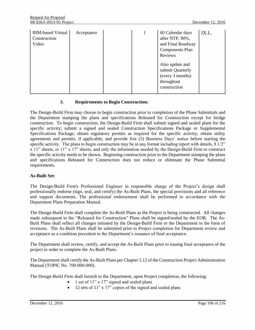
Request for Proposal
SR 836/I-395/I-95 Project December 12, 2016
December 12, 2016 Page 106 of 216
BIM-based Virtual
Construction
Video
Acceptance 1 60 Calendar days
after NTP, 90%,
and Final Roadway
Components Plan
Reviews
Also update and
submit Quarterly
(every 3 months)
throughout
construction
IX.L.
3. Requirements to Begin Construction:
The Design-Build Firm may choose to begin construction prior to completion of the Phase Submittals and
the Department stamping the plans and specifications Released for Construction except for bridge
construction. To begin construction, the Design-Build Firm shall submit signed and sealed plans for the
specific activity; submit a signed and sealed Construction Specifications Package or Supplemental
Specifications Package; obtain regulatory permits as required for the specific activity; obtain utility
agreements and permits, if applicable; and provide five (5) Business Days’ notice before starting the
specific activity. The plans to begin construction may be in any format including report with details, 8 1/2”
x 11” sheets, or 11” x 17” sheets, and only the information needed by the Design-Build Firm to construct
the specific activity needs to be shown. Beginning construction prior to the Department stamping the plans
and specifications Released for Construction does not reduce or eliminate the Phase Submittal
requirements.
As-Built Set:
The Design-Build Firm's Professional Engineer in responsible charge of the Project’s design shall
professionally endorse (sign, seal, and certify) the As-Built Plans, the special provisions and all reference
and support documents. The professional endorsement shall be performed in accordance with the
Department Plans Preparation Manual.
The Design-Build Firm shall complete the As-Built Plans as the Project is being constructed. All changes
made subsequent to the “Released for Construction” Plans shall be signed/sealed by the EOR. The As-
Built Plans shall reflect all changes initiated by the Design-Build Firm or the Department in the form of
revisions. The As-Built Plans shall be submitted prior to Project completion for Department review and
acceptance as a condition precedent to the Department’s issuance of final acceptance.
The Department shall review, certify, and accept the As-Built Plans prior to issuing final acceptance of the
project in order to complete the As-Built Plans.
The Department shall certify the As-Built Plans per Chapter 5.12 of the Construction Project Administration
Manual (TOPIC No. 700-000-000).
The Design-Build Firm shall furnish to the Department, upon Project completion, the following:
1 set of 11” x 17” signed and sealed plans
12 sets of 11" x 17” copies of the signed and sealed plans

Request for Proposal
SR 836/I-395/I-95 Project December 12, 2016
December 12, 2016 Page 107 of 216
Tree Disposition Plan and Landscape Plan
1 signed and sealed copy of the Bridge Load Rating based on as-built conditions
12 sets of final documentation (if different from final component submittal)
2 (two) Final Project CD’s
4. Milestones:
Component submittals, in addition to the plan submittals listed in the previous section, will be required. In
addition to various submittals mentioned throughout this document the following milestone submittals will
be required:
Permit applications and subsequent Request for Additional Information (RAI)
correspondence for Department Review
Approved Permits Package
Pavement Design Package
Typical Section Package
Design Exception and Variation Package
Stormwater Management Report
Noise and Vibration
5. Railroad/Transit Submittals:
Six sets of certain plan sheets, specifications, and documents are required for review by both railroad and
MDT. The sets are to be mailed to the District Rail Administrator for distribution to FECR and MDT. The
Design-Build Firm is required to coordinate with FECR and MDT to identify specific documentation
required by such agencies for approval of construction activities of the Design-Build Firm’s proposed
design. The required sheets are:
Key Sheet
Typical Section(s)
Plan & Profile Sheet(s)
Rail-highway grade crossing detail sheet
Signing and Pavement Marking Sheet(s)
Cross Section Sheets
List of Potential Utility Conflicts
Some of the required documents include, but are not limited to:
Quality Management Plan (QMP)
Construction Safety Plan
Construction Schedule with Sequencing
Safety Certification
Formal Safety Certification of the Project is required. Safety Certification is the process of verifying that
Operating System elements comply with a formal list of safety requirements. The Design-Build Firm shall
adhere to the safety certification process outlined in MDT’s System Safety and Security Certification
Program Plan, Revision 5, June 2011. Each safety and security certification plan is project specific and the
Design-Build Firm will develop the plan for this project and provide it to MDT for review and approval by
the 60% design submittal.
The project System Safety and Security Certification Plan will fulfill the requirements to comply with

Request for Proposal
SR 836/I-395/I-95 Project December 12, 2016
December 12, 2016 Page 108 of 216
Federal Transportation Administration (FTA) State Safety Oversight Rule (49 CFR Part 659) and the
Department Rule 14-15.017, F.A.C. In supporting the safety certification process, the Design-Build Firm
shall carry out a detailed accounting of all the correspondence and documentation to verify that all safety
related requirements, activities, tests, inspections and action items have been completed and satisfied and
shall document these results in a Safety Report which shall be submitted to MDT Engineering, Planning
and Development Office for its review and acceptance 30 Calendar days prior to the Design-Build Firm’s
written application for Substantial Completion.
The Design-Build Firm performing the safety and security certification shall perform a number of tasks to
verify and document the level of safety to be certified. These tasks are identified below. Other subtasks
may be identified in the design or construction phase, as needed by the project schedule or activities.
1. Identify safety requirements, current design assumptions and documents developed by the
Design-Build Firm, and other relevant requirements from Local, State and Federal sources
as they may impact the level of safety provided in the current Metromover system.
2. Verify the incorporation of safety and security requirements in the final design documents:
identify and resolve all open items.
3. Verify design by attestation (letter), inspection or conduct of subsystem/integrated test
procedures.
4. Verify operating and maintenance rules and/or procedures by review and pre-revenue tests.
5. Verify final safety open item close-out and/or identification of alternate measures
(“workarounds”) to satisfy safety requirements.
6. Develop a final safety and security certification report.
7. Prepare final certification documents; signed and sealed by a current and active
professional engineer registered in the State of Florida.
General Procedures for Adjacent and Transit Right-of-Way Construction Activity
The Design-Build Firm contemplating any construction activity adjacent to or on an MDT facility, structure
or property, including any excavation, maintenance, restoration, demolition, or use of MDT real property,
should provide, for review, three (3) copies of their drawings and three (3) copies of their calculations,
showing the relationship between their project and the MDT facilities.
Sufficient drawings and details should be submitted to facilitate MDT’s review of the effects that the
proposed project may or may not have on the MDT facilities. A MDT review requires internal circulation
of the construction drawings to concerned Divisions. Minimum review time for MDT is thirty (30) Calendar
days. Drawings normally required for review, but are not limited to, are:
Site Plan
Demolition Plans
Maintenance of Traffic Plans
Staging Plans
Drainage Area Maps and Drainage Calculations

Request for Proposal
SR 836/I-395/I-95 Project December 12, 2016
December 12, 2016 Page 109 of 216
Sections showing foundations and MDT Structures
Structural drawings (provide relative sections showing MDT)
Column load tables
Pertinent drawings detailing an impact on MDT facilities
A copy of the geotechnical report
If uncertainty exists on the possible impacts a project may have on the MDT facilities, and before making
a formal application for a review of a construction project adjacent to the MDT System, the developer or
his agent may contact the Chief, Right-of-Way and Utilities Division, at (786) 469-5244.
Sheeting and shoring drawings should be accompanied by calculations and shall be signed and sealed by a
Professional Engineer licensed in the State of Florida. The drawings and calculations should contain
comments, details, notes, and instructions describing the proposed sequence of construction. In the case
that the actual guideway structure is being shored, professional attestation (in writing) of the Metromover
system to be safe, to continue normal operations, is required.
When the design of foundations and site work of the project has progressed to the point considered complete
and ready for review, the drawings and calculations, as applicable, should be sent to:
Miami-Dade Transit
Chief
Right-of-Way and Utilities
Miami-Dade Transit
MDT-Overtown Transit Village
701 N.W. 1ST Court, Suite 1500
Miami, FL 33136
A period of thirty (30) Business Days should be allowed for review of the drawings and calculations.
Fifteen (15) Business Days should be allowed for each successive review as required.
The Design-Build Firm is required to address any construction impact on Pedestrian movements to the
Museum Park Metromover Station. This can be addressed by the Design-Build Firm as part of the
Maintenance of Traffic Plans
As per the MDT permit, no work (boom trucks, cherry pickers, excavators, front loaders, boring trucks,
scissor lifts, cranes, etc.) shall be performed within 30 feet zone extending outward from the outer most
edges of the MDT’s metrorail/metromover guideway unless a MDT spotter is present. The cost for the
MDT spotter is $60 per hour including one hour travel time, 30 minutes to and from the project, to be
included in the pay items of work for which the spotter will be required.
The Design-Build Firm is required to reimburse MDT for MDT’s cost of providing escorts, spotters and
support services for adjacent construction where access is required into the operating
Metrorail/Metromover system; and/or the system is impacted. The Design-Build Firm shall also reimburse
MDT for all associated costs of the bus “bridge” for all Metromover loops (Brickell, Downtown, and
Omni) to maintain normal service if the system is deemed unsafe to operate due to this project. As part of
the review procedure, and before any work may proceed, the Design-Build Firm will be required to sign a
letter accepting this obligation.
The Agreement between Metropolitan Dade County, Florida, and the Florida Department of

Request for Proposal
SR 836/I-395/I-95 Project December 12, 2016
December 12, 2016 Page 110 of 216
Transportation dated August 20, 1979, is under Attachment A-27.
The applicant must receive written approval for the design of a given project by the MDT Assistant
Director of the Engineering, Planning and Development Office or designee, or MDT Fire/Life Safety
Technical Committee Chairperson (as applicable), prior to the start of construction.
Project Documents shall be reviewed by the appropriate MDT Divisions for possible impact on MDT
facilities and operations, including all elements associated with the construction of the project and any
temporary protection/shoring system needed to preserve the system’s safety and integrity.
Each “Part” of the project’s design shall be reviewed and accepted by all pertinent MDT Divisions.
Limitations:
MDT Metromover Closures:
Closures of the Metromover will be required for any construction activities where personnel and/or
equipment come within 10 feet of the guideway superstructure or as deemed by MDT. Closure of
Metromover for construction access will be limited to non-operational service hours as determined by
MDT. Metromover restrictive hours (non-revenue) should be from 1:00 AM to 4:00 AM. All closures
shall be coordinated with MDT for Holidays, Specific Events and maintenance operations. System
closures require extensive early coordination and planning between the requestor and MDT. MDT
reserves the right to deny system closure requests based on operational needs.
A late opening on a Sunday morning, subject to operational service beginning no later than 10:00 AM may
be considered at the discretion of MDT. A bus “bridge” shall be required for any closure interrupting
operational service hours. All proposed extended closure opportunities shall be presented as an ATC.
Extended closures shall not be allowed except those specifically approved through the ATC process. All
cost associated with MDT closures are the responsibility of the Design-Build Firm.
MDT Metrorail Closures:
Any closures required for the Metrorail shall be coordinated with MDT.
MDT Settlement Monitoring & Action Plan:
A Settlement Monitoring & Action Plan (SMAP) must be submitted to MDT and approved prior to any
construction activities. The minimum requirements to be included in the SMAP are as follows:
o An inspection of the Metromover components (i.e., guideway, pier cap, bearings and girders)
prior to construction. The inspection procedure, approach, and findings shall be fully
documented in report format, including photos clearly identifying location, date, observation,
etc.
o A complete and detailed monitoring procedure, including but not limited to the type of
equipment, monitoring marks on guideway components, tabulation of readings, frequency of
readings, reporting, analysis of readings, actions to be taken, etc. This SMAP is required to
evaluate the settlement and cumulative movement/rotation/translation of the pier and impacts
to Metromover components. As a minimum, readings shall be taken immediately prior to
guideway turnover to MDT each evening. Continuous monitoring shall be performed during
critical operations where movement of the guideway could potentially occur. Construction

Request for Proposal
SR 836/I-395/I-95 Project December 12, 2016
December 12, 2016 Page 111 of 216
operations shall be halted immediately if the readings show a deviation value greater than
acceptable by MDT. o The SMAP must be approved by MDT before any construction activity begins in the area. Once
the SMAP is approved, the Design-Build Firm will set up all proposed survey points in the
field, a set of initial survey readings will be taken, signed and sealed data of initial readings
will be submitted to MDT for review and approval and final approval of initial reading by MDT
shall take place before starting any construction activities without exception. This set of
readings will be the baseline of future reference for new readings. Surveying nails, screws, or
any penetrations to the structures will not be allowed. The Design-Build Firm is to use durable,
environmentally friendly targets glued to the elements; set up to be approved by MDT prior to
commencing any work. o Each reading must establish which phase of construction has been completed when the reading
was made and the reading must indicate clearly the date taken.
o The SMAP must include the process to address corrective action by the Design-Build Firm in
case the readings show a deviation value greater than acceptable by MDT. All costs incurred
in addressing corrective actions will be borne by the Design-Build Firm. The SMAP must
include a mitigation plan in the form of a Plan of Action.
o Closure of the Metromover will only be allowed during no-revenue hours of 1:00 AM to 4:00
AM. No additional closures to the system will be allowed. In the event that interruption of
service exceeds four continuous hours of service, the Design-Build Firm must notify MDT
immediately. A bus bridge will be provided to shuttle passengers between affected
Metromover stations. The cost of the Bus Bridge will be the Design-Build Firm’s sole
responsibility.
MDT Change Review Board Requirement:
The Design-Build Firm is responsible to submit the design plans relating to the Metromover Bridge, as
required, to the MDT Change Review Board (CRB) for review and comments. The CRB process will
authorize, control, implement and record changes to the as-built and safety certified configuration of the
Metromover Bridge.
J. Contract Time:
The Design-Build Firm shall establish the Proposed Contract Time for the Total Project. In no event shall
the Proposed Contract Time exceed 1825 Calendar days. The Proposed Contract Time shall be submitted
with the Price Proposals.
K. Project Schedule:
The Design-Build Firm shall submit a schedule, in accordance with Subarticle 8-3.2, Design-Build Division
I Specifications (Attachment A-02). The Design-Build Firm’s schedule shall allow for up to twenty (20)
Business Days review time for the Department’s review of all submittals with the exception of Signature
Bridge submittals. The review of Signature Bridge submittals requires Central Office involvement and the
schedule shall allow for up to thirty-five (35) Business Days for these reviews.
Design-Build Firm shall submit the Foundation Construction submittals in accordance with Section 455
(Attachment A-03), for Department review.
Listed below are Specific Events and Organizations/Businesses hosting regular events in the vicinity of or
possibly impacted by the project:

Request for Proposal
SR 836/I-395/I-95 Project December 12, 2016
December 12, 2016 Page 112 of 216
Art Basel Miami Beach:
https://www.artbasel.com/miami-beach
Miami International Boat Show:
http://www.miamiboatshow.com/
Miami Marathon:
http://www.themiamimarathon.com/
Miami Grand Prix Formula E
http://miami.fiaformulae.com/en/guides.aspx
South Beach Food and Wine Festival
http://www.sobefest.com/
Ultra Music Festival
http://www.ultramusicfestival.com/
Yacht & Brokerage Show:
http://www.showmanagement.com/miami_boat_show_2015/event/
Winter Party Week/Spring Break
http://www.winterparty.com/guide
Winter Music Conference/Spring Break:
http://wintermusicconference.com/events/
Adrienne Arsht Center for Performing Arts Events:
http://www.arshtcenter.org/Tickets/Calendar/
American Airlines Arena Events:
http://www.aaarena.com/events
Critical Mass:
http://www.themiamibikescene.com/p/miami-critical-mass-guidelines.html
Mercedes Benz Corporate Run:
http://www.mercedesbenzcorporaterun.com/miami.php
Memorial Day Weekend (Thurs.-Mon.)
New Year’s Eve
Art Deco Weekend
http://www.artdecoweekend.com/
Miami Beach Gay Pride Parade
https://www.miamibeachgaypride.com/parade
Halloween
White Party Week
http://whiteparty.org/
Marlins Park
http://miami.marlins.mlb.com/mia/ballpark/
The minimum number of activities included in the schedule shall be those listed in the Schedule of Values,
and those listed below:
Anticipated Award Date
Pre-Design Utility Meeting
Pre-Construction Meeting(s)
Design Durations
Design Submittals
Aesthetic Submittals
Shop Drawing Submittals

Request for Proposal
SR 836/I-395/I-95 Project December 12, 2016
December 12, 2016 Page 113 of 216
Design Survey
Submittal Reviews by the Department and FHWA
Design Review by the Department and MDT/ Acceptance Milestones
Materials Quality Tracking
Geotechnical Investigation
Start of Construction
Clearing and Grubbing
Construction Mobilization
Embankment/Excavation
Environmental Permit Acquisition
Foundation Design
Foundation Construction
Detailed Pier Construction Sequencing
MDT Metromover closures within operational service hours
MDT Pier Cap Replacement and Removal of Existing Pier
Substructure Design
Substructure Construction
Superstructure Design
Superstructure Construction
Walls Design
Walls Construction
Roadway Design
Roadway Construction
Signing and Pavement Marking Design
Signing and Pavement Marking Construction
Signalization and Intelligent Transportation System Design
Signalization and Intelligent Transportation System Construction
Lighting Design
Lighting Construction
Maintenance of Traffic Design
Landscape Concept Plan
Existing Tree Inventory Plan
Tree Disposition Plan
Landscape Plan
Landscape Establishment Plan
Landscape Design
Landscape Construction
Permit Submittals
Maintenance of Traffic Set-Up (per duration)
Erosion Control
Holidays and Specific Events (shown as non-work days)
Additional Construction Milestones as determined by the Design-Build Firm
ITS Burn-In Period
ITS Testing and Integration
Final Completion Date for All Work
Final Signed and Sealed As-Built Plans
Tolling Design (MDX specific)

Request for Proposal
SR 836/I-395/I-95 Project December 12, 2016
December 12, 2016 Page 114 of 216
Tolling Construction (MDX Specific)
Additional activities required by an ATC that are not stated above
L. Key Personnel/Staffing:
The Design-Build Firm’s work shall be performed and directed by key personnel identified in the Letter of
Response and/or Technical Proposal by the Design-Build Firm. In the event a change in key personnel is
requested, the Design-Build Firm shall submit the qualifications of the proposed key personnel and include
the reason for the proposed change. Any changes in the indicated personnel shall be subject to review and
approval by the District Construction Engineer. The Department shall have sole discretion in determining
whether or not the proposed substitutions in key personnel are comparable to the key personnel identified
in the Letter of Response and/or Technical Proposal. The Design-Build Firm shall have available
professional staff meeting the minimum training and experience set forth in Chapter 455, Florida Statutes.
M. Partner/Teaming Arrangement:
Partner/Teaming Arrangements of the Design-Build Firm (i.e., Prime Contractor or Lead Design Firm)
cannot be changed after submittal of the Letter of Response without written consent of the Department. In
the event a change in the Partner/Teaming Arrangement is requested, the Design-Build Firm shall submit
the reason for the proposed change. Any changes in the Partner/Teaming Arrangement shall be subject to
review and approval by the Department’s Chief Engineer. The Department shall have sole discretion in
determining whether or not the proposed substitutions in Partner/Teaming Arrangements are comparable
to the Partner/Teaming Arrangements identified in the Letter of Response and/or Technical Proposal.
N. Meetings and Progress Reporting:
The Design-Build Firm shall anticipate periodic meetings with Department personnel and other agencies
as required for resolution of design and/or construction issues. These meetings may include:
Department technical issue resolution
Local government agency coordination
Maintenance of Traffic Workshop
Pavement Design Meeting
Permit agency coordination
Scoping Meetings
System Integration Meetings
During design, the Design-Build Firm shall meet with the Department’s Project Manager at least on a
monthly basis and provide a one month look ahead of the activities to be completed during the upcoming
month.
During construction, the Design-Build Firm shall meet with the Department’s Project Manager on a weekly
basis and provide a one-week look ahead for activities to be performed during the coming week.
The Design-Build Firm shall meet with the Department’s Project Manager at least thirty (30) Calendar days
before beginning system integration activities. The purpose of these meetings shall be to verify the Design-
Build Firm’s ITS and signalization integration plans by reviewing site survey information, proposed
splicing diagrams, IP addressing schemes, troubleshooting issues, and other design issues. In addition, at
these meetings the Design-Build Firm shall identify any concerns regarding the Integration and provide

Request for Proposal
SR 836/I-395/I-95 Project December 12, 2016
December 12, 2016 Page 115 of 216
detailed information on how such concerns will be addressed and/or minimized.
The Design-Build Firm shall provide all documentation required to support system integration meetings,
including detailed functional narrative text, system and subsystem drawings and schematics. Also included
shall be the documentation to demonstrate all elements of the proposed design which includes, but is not
limited to: technical, functional, and operational requirements, ITS/communications, equipment,
termination/patch panels, performance criteria, and details relating to interfaces to other ITS subsystems.
System Integration Meetings will be held on mutually agreeable dates.
All action items resulting from the System Integration Meeting shall be satisfactorily addressed by the
Design-Build Firm and reviewed and approved by the Department.
The Design-Build Firm shall, on a monthly basis, provide written progress reports that describe the items
of concern and the work performed on each task.
O. Public Involvement:
1. General:
Public involvement is an important aspect of the Project. Public involvement includes communicating to
all interested persons, groups, and government organizations information regarding the development of the
Project. A Public Involvement Consultant (PIC) will be hired by the Department to carry out an exhaustive
Public Involvement Campaign and a marketing effort. The Design-Build Firm will continue to be part of
the Public Involvement effort but on a limited basis as described below.
2. Community Awareness:
The Design-Build Firm will review and comment on a Community Awareness Program provided by the
PIC for the Project.
3. Public Meetings:
The Design-Build Firm shall provide all support necessary for the PIC to hold various public meetings,
which may include:
Kick-off or introductory meeting
MPO Transportation Technical Committee Meetings
MPO Meetings
Public Information Meetings
Elected and appointed officials
Special interest groups (private groups, homeowners associations, environmental
groups, minority groups and individuals)
Other meetings as determined by the Department, in its sole discretion.
The Design-Build Firm shall include attendance at two meetings per month for the term of the contract to
support the public involvement program.
For any of the above type meetings the Design-Build Firm shall provide all technical assistance, data and
information necessary for the PIC to produce display boards, printed material, video graphics, computerized

Request for Proposal
SR 836/I-395/I-95 Project December 12, 2016
December 12, 2016 Page 116 of 216
graphics, etc., and information necessary for the day-to-day exchange of information with the public, all
agencies and elected officials in order to keep them informed as to the progress and impacts that the
proposed Project will create. This includes workshops, information meetings, and public hearings.
The Design-Build Firm shall, on an as-needed basis, attend the meetings with an appropriate number of
personnel to assist the Department's Project Representative/PIC. The Design-Build Firm shall forward all
requests for group meetings to the PIC. The Design-Build Firm shall inform the PIC of any meetings with
individuals that occur without prior notice.
4. Public Workshops, Information Meetings:
The Design-Build Firm shall provide all the support services listed in No. 3 above. All legal/display ads
announcing workshops, information meetings, and public meetings will be prepared and paid for by the
PIC.
The Department will be responsible for the legal/display advertisements for design concept acceptance. The
PIC will be responsible for preparing and mailing (includes postage) for all letters announcing workshops
and information meetings.
5. Public Involvement Data:
The Design-Build Firm is responsible for the following:
Coordinating with the Public Involvement Consultant.
Identifying possible permit and review agencies and providing names and contact
information for these agencies to the PIC.
Providing required expertise (staff members) to assist the PIC on an as-needed
basis.
Preparing color graphic renderings and/or computer generated graphics to depict
the proposed improvements for coordination with the Department, local
governments, the Urban Design Guidelines Committee, and other agencies.
The collection of public input occurs throughout the life of the Project and requires maintaining files,
newspaper clippings, letters, and especially direct contacts before, during and after any of the public
meetings. Articles such as those mentioned shall be provided to the PIC for their use and records.
In addition to collecting public input data, the Design-Build Firm may be asked by the PIC to prepare
responses to any public inquiries as a result of the public involvement process. The Department shall review
all responses prior to mailing.
P. Quality Management Plan (QMP):
1. Design:
The Design-Build Firm shall be responsible for the professional quality, technical accuracy and
coordination of all surveys, designs, drawings, specifications, geotechnical and other services furnished by
the Design-Build Firm under the Department Contract.
The Design-Build Firm shall provide a Design Quality Management Plan, which describes the Quality
Control (QC) procedures to be utilized to verify, independently check, and review all design drawings,

Request for Proposal
SR 836/I-395/I-95 Project December 12, 2016
December 12, 2016 Page 117 of 216
specifications, and other documentation prepared as a part of the contract. In addition the QMP shall
establish a Quality Assurance (QA) program to confirm that the Quality Control procedures are followed.
The Design-Build Firm shall describe how the checking and review processes are to be documented to
verify that the required procedures were followed. The QMP may be one utilized by the Design-Build
Firm, as part of their normal operation or it may be one specifically designed for this Project. The Design-
Build Firm shall submit a QMP within fifteen (15) working days following issuance of the written Notice
to Proceed. A marked up set of prints from the Quality Control review will be sent in with each review
submittal. The responsible Professional Engineers or Professional Surveyor that performed the Quality
Control review, as well as the QA manager will sign a statement certifying that the review was conducted.
The Design-Build Firm shall, without additional compensation, correct all errors or deficiencies in the
surveys, designs, drawings, specifications and/or other services.
2. Construction:
The Design-Build Firm shall be responsible for developing and maintaining a Construction Quality Control
Plan in accordance with Section 105 of Standard Specifications which describes their Quality Control
procedures to verify, check, and maintain control of key construction processes and materials.
The sampling, testing and reporting of all materials used shall be in compliance with the Sampling, Testing
and Reporting Guide (STRG) provided by the Department. The Design-Build Firm will use the
Department’s database(s) to allow audits of materials used to assure compliance with the STRG. The
Department has listed the most commonly used materials and details in the Department’s database. When
materials being used are not in the Department’s database list, the Design-Build Firm shall use appropriate
material details from the STRG to report sampling and testing. Refer to the State Materials Office website
for instructions on gaining access to the Department’s databases:
http://www.dot.state.fl.us/statematerialsoffice/quality/programs/qualitycontrol/contractor.shtm
Prepare and submit to the Engineer a Job Guide Schedule (JGS) using the Department database in
accordance with Section 105 of Standard Specifications.
The Department shall maintain its rights to inspect construction activities and request any documentation
from the Design-Build Firm to ensure quality products and services are being provided in accordance with
the Department’s Materials Acceptance Program.
Q. FHWA Project Management Plan (PMP)
In accordance with FHWA Major Project Guidelines, the Department is required to prepare an initial
Project Management Plan (PMP) for the Project. The PMP defines the roles, responsibilities and procedures
for project implementation. Refer to Reference Document RD-04 The PMP will need to be updated by the
Design-Build Firm subsequent to the execution of the contract and prior to initiating construction activities.
R. Liaison Office:
The Department and the Design-Build Firm will designate a Liaison Office and a Project Manager who
shall be the representative of their respective organizations for the Project.
S. Engineers Field Office:

Request for Proposal
SR 836/I-395/I-95 Project December 12, 2016
December 12, 2016 Page 118 of 216
The Design-Build Firm will provide an Engineers Field Office in accordance with Special Provision 109
of the Special Provisions. See Attachment A-30. The office size provided shall be 5,000 SF and shall be
one single office located within one mile from the project. The office requirements specified in Section
109-2 of Attachment A-30 shall be prorated to meet the requirements of the specified office size. The
office shall include an alarm system.
T. Schedule of Values:
The Schedule of Values approved by the Department will be the basis for determining each monthly
progress estimate and the final estimate. The quantities will be compared with the project schedule to
determine the percentage earned. The percentage shall be that portion of the work completed as compared
to the total work contracted. The Design-Build Firm shall assign the Schedule of Values to the activities
in the CPM schedule. The assignment of values to scheduled activities must be approved by the Department
prior to the first monthly progress estimate and prior to any invoicing by the Design-Build Firm pursuant
to the Cash Availability Schedule for the Project. The monthly progress estimates cut-off date will be the
first Sunday of the month.
The Design-Build Firm’s Schedule of Values shall include Landscaping as a specific line item. The cost of
tree relocation and removal, as well as, the removal of invasive plant species shall be included in the
Schedule of Values under Clearing and Grubbing.
Prompt Payment Law:
Participants providing goods and services to the Department should be aware of the following time frames.
The Department has five (5) Business Days from the date the monthly progress estimate is created to inspect
and approve the goods and services. The Department has twenty (20) days to deliver a request for payment
(voucher) to the Department of Financial Services. The twenty (20) days are measured from the latter of
the date the invoice is received or the goods or services are received, inspected and approved.
Invoices will be reduced for amounts invoiced and earned but in excess of the amounts available per
the Cash Availability Schedules as outlined in Section VI.L.
If a payment is not available within forty (40) days of the Department’s receipt of an invoice payable
pursuant to the Cash Availability Schedule for the Project, a separate interest penalty at a rate as established
pursuant to Section 55.03(1), Florida Statutes, will be due and payable, in addition to the payable invoice
amount, to the Design-Build Firm. Interest penalties of less than one (1) dollar will not be enforced unless
the Design-Build Firm requests payment. Invoices that have to be returned to a Design-Build Firm because
of Design-Build Firm preparation errors will result in a delay in payment. The invoice payment
requirements do not start until a properly completed invoice pursuant to the Cash Availability Schedule is
provided to the Department.
A Vendor Ombudsman has been established within the Department of Financial Services. The duties of
this individual include acting as an advocate for contractors/vendors who may be experiencing problems in
obtaining timely payment(s) from a state agency. The Vendor Ombudsman may be contacted at (850)413-
5516 or by calling the Department of Financial Services Division of Consumer Services, 1-877-693-5236.
U. Computer Automation:
The Project shall be developed utilizing computer automation systems in order to facilitate the development

Request for Proposal
SR 836/I-395/I-95 Project December 12, 2016
December 12, 2016 Page 119 of 216
of the contract plans. Various software and operating systems were developed to aid in assuring quality
and conformance with Department policies and procedures. The Department supports MicroStation and
GEOPAK as its standard graphics and roadway design platform as well as Autodesk’s AutoCAD Civil 3D
as an alternate platform. Seed Files, Cell Libraries, User Commands, MDL Applications and related
programs developed for roadway design and drafting are in the FDOT CADD Software Suite. Furnish As-
Built documents for all building-related components of the project in AutoCAD format. It is the
responsibility of the Design-Build Firm to obtain and utilize current Department releases of all CADD
applications.
The Design-Build Firm will be required to furnish the Project's CADD files after the plans have been
Released for Construction. The Design-Build Firm's role and responsibilities are defined in the
Department's CADD Manual. The Design-Build Firm will be required to submit final documents and files
which shall include complete CADD design and coordinate geometry files in Intergraph / Micro station
format.
As part of the As-Built Set deliverables, field conditions shall be incorporated into MicroStation and/or
AutoCAD design files. Use the cloud revision utility as well as an “AB” revision triangle to denote field
conditions on plan sheets.
V. Construction Engineering and Inspection:
The Department is responsible for providing Construction Engineering and Inspection (CEI) and Quality
Assurance Engineering.
The Design-Build Firm is subject to the Department’s Independent Assurance (IA) Procedures.
W. Testing:
The Department or its representative will perform verification and resolution sampling and testing activities
at both on site, as well as off-site locations such as pre-stress plants, batch plants, structural steel and weld,
fabrication plants, etc., in accordance with the latest Specifications.
X. Value Added:
The Design-Build Firm may provide Value Added Project Features, in accordance with Section 5-14 of the
Department’s Division I Design-Build Specifications (Attachment A-02) for the following features:
Roadway features;
Roadway drainage systems;
Approach slabs;
Superstructure;
Substructure;
Concrete defects;
Structural steel defects;
Stay/suspender cables;
Post-tensioning systems; and
And any other products or features the Design-Build Firm desires.

Request for Proposal
SR 836/I-395/I-95 Project December 12, 2016
December 12, 2016 Page 120 of 216
The Design-Build Firm shall develop the Value Added criteria, measurable standards, and remedial work
plans in the Design-Build Firm's technical proposal for features proposed by the Design-Build Firm.
Y. Adjoining Construction Projects:
The Design-Build Firm shall be responsible for coordinating construction activities with other construction
Projects that are impacted by or impact this Project. This includes Projects under the jurisdiction of local
governments, the Department, or other regional and state agencies.
Adjacent projects include:
1. FPID 425598-1 SR 7/NW 7 Ave from NW 8 St to NW 36 St – Reconstruction
2. FPID 429300-3 I-95 Pavement Reconstruction – North Segment
3. FPIDs 417740-8-92-01, 417740-9-92-01 and 417740-9-92-02 I-95 Express DMS and Toll Sign
Panel Replacement Project
4. MDX 83628: SR 836 Auxiliary Lanes and Interchange Improvements
5. FPID-436522-1-SRA1A/MacArthur Causeway – East Bridge #870077 – Bridge
Repair/Rehabilitation
Z. Issue Escalation:
In the event issues arise during prosecution of the work, the resolution of those issues will be processed as
described below unless revised by a project specific Partnering Agreement:
The escalation process begins with the Construction Project Manager. All issues are to be directed to the
Construction Project Manager. If the issue cannot be resolved by the Construction Project Manager in
coordination with the Resident Engineer and Design Project Manager as applicable, the Construction
Project Manager shall forward the issue to the District Construction Engineer who will coordinate with the
District Design Engineer, as applicable. Each level shall have a maximum of five (5) Business Days to
answer, resolve, or address the issue. The Design-Build Firm shall provide all supporting documentation
relative to the issue being escalated. The five (5) Business Day period begins when each level in the issue
escalation process has received all required supporting documentation necessary to arrive at an informed
and complete decision. The five (5) Business Day period is a response time and does not infer resolution.
Questions asked by the Department may be expressed verbally and followed up in writing within one (1)
Business Day. Responses provided by the Design-Build Firm may be expressed verbally and followed up
in writing within one (1) Business Day. Once a response is received from the District Construction
Engineer, the Construction Project Manager will respond to the Design-Build Firm in a timely manner but
not to exceed three (3) Business days.
The Design-Build Firm shall provide a similar issue escalation process for their organization with personnel
of similar levels of responsibility.
Should an impasse develop, the Dispute Review Board shall assist in the resolution of disputes and claims
arising out of the work on the Contract.
The Department shall be the sole authority having jurisdiction regarding disputes over issues of structural
integrity.
AA. Maintenance During Construction

Request for Proposal
SR 836/I-395/I-95 Project December 12, 2016
December 12, 2016 Page 121 of 216
The Design-Build Firm shall perform maintenance activities for the length of the Total Project, right-of-
way to right-of-way, including any right-of-ways owned or maintained by local agencies that are impacted
by the Project work, as defined in Attachments A-32, A-1295 and MDXA-16. The Design-Build Firm shall
perform maintenance activities in accordance with the Contract Documents, including but not limited to
the ITS Maintenance Responsibilities as provided in Attachment A-12. The Design-Build Firm’s
maintenance responsibilities will end with final acceptance of the Total Project by the Department, unless
otherwise noted in the Contract Documents.
Area shown on maintenance maps, as defined in Attachments A-32, A-1295, and MDXA-16, may require
adjustments and may be increased by the Department, in its sole discretion and without additional
compensation to the Contractor, up to additional 2 acres. If Project Limits are extended, the Design-Build
Firm shall be responsible for the maintenance of the extension.
Subarticles 7-11.1 and 7-11.2 of Attachment A-02 are amended and restated to read as provided in the
document titled Preservation of Property in Attachment A-03.
Section 107 of the Standard Specifications is amended and restated to read as provided in the document
titled Litter Removal and Mowing in Attachment A-03.
IX. Design and Construction Criteria.
A. General:
All design and construction work completed under the Contract shall be in accordance with the United
States Standard Measures.
FHWA will have full oversight of this Project during both design and construction.
The Design-Build Firm shall provide a minimum of 10 foot high opaque fence around any long term (over
15 Calendar days) staging/stockpiling. No advertising signage or company logos is allowed on any fencing
or fabric covering a fence.
B. Vibration, Settlement Monitoring and Construction Noise:
Vibration and Settlement Monitoring
The Design-Build Firm is responsible for evaluating the need for, design of, and the provision of any
necessary precautionary features to protect existing structures from damage, including, at a minimum,
selecting construction methods and procedures that will prevent damage.
The Department and MDX have identified vibration sensitive sites along the Project corridor. The Design-
Build Firm shall be responsible for the identification of and coordination with vibration sensitive sites
affected by the Work for the duration of construction.
Vibration sensitive sites include the following:
I-395 Specific
St. John Baptist Church;
Patricia and Phillip Frost Museum of Science;

Request for Proposal
SR 836/I-395/I-95 Project December 12, 2016
December 12, 2016 Page 122 of 216
Perez Art Museum Miami;
Christ Church;
Marquis Miami;
Ziff Opera House; and
John S. and James L. Knight Concert Hall.
End I-395 Specific
MDX Specific
Grove Park Historic District, Miami, FL 33125
o 1491 NW South River Drive
o 1501 NW South River Drive
o 1480 NW South River Drive
o 1458 NW South River Drive
o 1459 NW South River Drive
o 935 NW 15th Avenue
End MDX Specific
The Design-Build Firm shall submit for the Department’s acceptance a Settlement and Vibration
Monitoring Plan (SVMP) as part of the 90% plans submittal. The SVMP shall be updated throughout the
construction period. The Design-Build Firm is responsible for establishing maximum settlement and
vibration thresholds equivalent to or lower than the Department Specifications requirements for all
construction activities, including vibratory compaction operations and excavations.
Submittals for Settlement and Vibration Monitoring Plan (SVMP) shall include the following as a
minimum:
Identify any existing structures, in addition to those listed herein, that will be
monitored for vibrations during the construction period.
Establish the maximum vibration levels. The maximum vibration levels stated for
existing structures shall not be exceeded.
Identify any existing structures in addition to those listed herein that will be
monitored for settlement during the construction period.
Establish the maximum settlement levels for the existing structures that must not
be exceeded. The maximum settlement level stated shall not be exceeded.
Identify any existing structures in addition to those identified that require pre-
construction and post-construction surveys.
Identify sensitive medical facilities and equipment, and critical time windows of
vibration sensitive activities.
The Department will perform the review of Vibration and Settlement submittals in accordance with
Department Specifications.
Construction Noise
The Design-Build Firm shall monitor and control noise as described in this section:
Terms Used
The following terms, when used within this section of the RFP “Construction Noise,” have the meaning set
forth below:

Request for Proposal
SR 836/I-395/I-95 Project December 12, 2016
December 12, 2016 Page 123 of 216
Noise Sensitive Receptors: are adjacent to the project and include, but not limited to, businesses, residences,
museums, concert halls, hospitals, hotels, condominiums, residential and government building. This also
includes area Specific Events as listed in Section VIII.K.
Noise: is any audible sound which has the potential to annoy or disturb humans, or to cause an adverse
psychological or physiological effect on humans.
Daytime: refers to the period from 8 AM to 8 PM local time daily.
Nighttime: refers to the period from 8 PM to 8 AM local time daily.
Baseline Noise: shall be defined as the background noise levels that are measured prior to construction
work commencing.
Lmax: shall be defined as the maximum measured sound level at any time.
L10: shall be defined as the sound level exceeded 10 percent of the time for a specified monitoring period.
Construction Activities
The Design-Build Firm shall use means and methods of construction that minimize noise throughout all
phases of the Total Project. Location of mobile and stationary equipment such as air compressors,
generators, pumps, etc., shall be such as to cause the least disruption of businesses and residences in the
vicinity of the project. All equipment associated with the work must be equipped with noise suppression
devices which must be maintained in their original operating condition considering normal wear.
Manufacturer installed noise suppression devices such as mufflers, engine covers, insulation, etc. must not
be removed nor rendered ineffectual nor remain off the equipment while the equipment is in use. Additional
noise suppression, beyond standard manufacturer features, shall be used where necessary.
The Design-Build Firm is responsible for coordinating with all noise sensitive businesses for hours of
operations affected by noise and summarizing this information in the Noise Monitoring Control Plan
(NMCP).
In no case shall construction noise exceed the established L10 plus 5 dBA for a cumulative period of 2
minutes in any twenty minute period for daytime and nighttime.
Noise Monitoring and Control Plan
A Noise Monitoring and Control Plan (NMCP) shall be submitted for review and acceptance prior to the
start of construction. A pre-submittal of the Noise Sensitive Receptors shall be submitted prior to the full
NMCP for approval by the Engineer. Allow 14 Business Days for review. An updated NMCP shall be
submitted every 6 months thereafter, or whenever additional noise sensitive receptors are discovered, work
activities or work hours substantively change, or required by the Engineer for the duration of construction
activities.
The Design-Build Firm shall perform measurements to determine Lmax and L10 for daytime and nighttime
hours as part of the noise plan. All measurements shall be taken at the lot line for the noise sensitive
receptors. Noise measurements shall be collected over two non-consecutive days Monday through Saturday
and on Sunday at noise sensitive receptor locations. Baseline noise measurements shall be performed in the
absence of any contributing construction noise or noise from emergency signals, emergency equipment and

Request for Proposal
SR 836/I-395/I-95 Project December 12, 2016
December 12, 2016 Page 124 of 216
vehicles, emergency warning devices, and law enforcement activities (including training activities).
This plan shall also include the results of a noise analysis used to predict the noise levels associated with
work and equipment expected to be used within a 6-month period near noise sensitive receptors lot lines.
The Federal Highway Administration’s (FHWA) Roadway Construction Noise Model (RCNM) or
equivalent shall be used for construction noise prediction. The plan shall also describe any noise mitigation
measures that will be implemented to reduce noise levels.
The Noise Control Plan shall include:
1. A sketch showing the locations of noise sensitive receptors and Specific Events, including any
additional receptors identified.
2. The type of noise level measurement device that shall be used.
3. Daytime and Nighttime Measurements for Lmax and L10 at Noise Sensitive Receptors.
4. The nature of activities and equipment generating noise, which may affect noise sensitive receptors
(such as residential or businesses) in the area.
5. The project construction times of activities generating noise, which may affect noise sensitive
receptors in the area.
6. Analysis of predicted daytime and nighttime noise levels.
7. Description of the methods of controlling noise including, but not limited to, alternative hours of
operations, proposed noise abatement measures (such as noise barriers), alternative routes for
construction vehicles, alternative equipment, screening of stationary equipment, adequate
equipment maintenance, etc.
8. Noise monitoring tools and methods.
9. Community coordination plan.
10. Response procedure and actions to be taken for any noise level that exceeds the noise limits or
complaints specified in this section.
11. The complaint response and resolution procedures.
Monitoring
The Design-Build Firm shall monitor construction work per the following requirements:
1. Continuous noise level measurements shall be taken at each noise-sensitive receptor lot line and at
the Total Project right-of-way line adjacent to and during the construction work.
2. Construction noise measurements shall coincide with daytime and nighttime periods of maximum
noise-generating construction activity, and shall be performed during this time.
3. These monitors shall be capable of recording the noise values over a 24-hour period.
Noise from emergency signals, emergency vehicles, emergency warning devices, and law enforcement
activities (including training) are exempt from the provision of this section.
C. Geotechnical Services:
Driven Pile Foundations for Bridges and Major Structures
The Design-Build Firm shall determine whether the resistance factors used for pile design will be based on
static/statnamic load testing. Prepare a TSP for tests other than the Modified Quick Test, such as Osterberg
Cell Load Test or Statnamic Load Test. For Osterberg Cell Load Tests use the same loading and unloading
intervals, as well as the same loading times specified for the Modified Quick Test. Comply with the
instrumentation requirements of 455-2.4. Before the resistance factors for static/statnamic load testing may

Request for Proposal
SR 836/I-395/I-95 Project December 12, 2016
December 12, 2016 Page 125 of 216
be used for pile foundations in any of the following areas of the Project, a minimum number of successful
load tests must be performed in representative locations of that area:
I-395 Specific
Bridge No. Description Minimum No. of Tests & Locations
1 EN Connector 1 test between Station 208+00 to 210+00
2 ES Connector 1 test between Station 917+00 to 920+00
3 SE Connector 1 test between Station 109+00 to 110+00
4 WB Connector 1 test between Station 4035+00 to 4040+00
5W I-395 WB 1 test between Station 2040+00 to 2045+00
6W I-395 EB 1 test between Station 1045+00 to 1047+50
7E EB Connector 1 test between Station 3053+00 to 3060+00
8 I-395 WB (Signature
Span)
1 test in the near vicinity of West Pier
9 I-395 EB (Signature
Spain)
1 test in the near vicinity of East Pier
14 SR 836 Widening 1 test between Station 1018+00 to 1020+0
End I-395 Specific
MDX Specific
The minimum number of tests and their locations for driven pile foundations are tabulated below.
Bridge No. Description Minimum No. of Tests & Locations
870147 SR 836 WB 1 test between Station 1421+00 to 1428+00
870147 SR 836 WB 1 test between Station 1439+00 to 1447+00
870298 SR 836 EB 1 test between Station 1421+00 to 1428+00
870298 SR 836 EB 1 test between Station 1439+00 to 1444+00
870150 SR 836 WB 1 test between Station 1462+00 to 1467+00
870300 SR 836 EB 1 test between Station 1461+00 to 1468+00
870367 836 E-S Connector 1 test between Station 4476+00 to 4480+00
870456 SR 836 EB 1 test between Station 1476+00 to 1484+00
870366 SR 836 WB 1 test between Station 1477+00 to 1483+00
870370 SR 836 E-N Connector 1 test between Station 12482+00 to 12485+00
870363 SR 836 WB Connector 1 test in near vicinity to Station 3478+00
870724 Ramp L 1 test in near vicinity to Station 7495+00
16 SR 836 EB Connector 1 test between Station 2407+00 to 2409+00
17 SR 836 EB Connector 3 test between Station 9455+00 to 9470+00
18 Ramp I 1 test between Station 4470+00 to 4472+00
19 SR 836 EB Connector 1 test between Station 2430+00 to 2436+00
20 SR 836 EB Connector
2 test between Station 2436+00 to 2448+00
21 Ramp J 2 test between Station 7480+00 to 7490+00
22 Ramp M 1 test between Station 6442+00 to 6448+00
23 SR 836 WB Connector 1 test between Station 3442+00 to 3448+00
24 SR 836 WB Connector 1 test between Station 3454+00 to 3468+00
End MDX Specific

Request for Proposal
SR 836/I-395/I-95 Project December 12, 2016
December 12, 2016 Page 126 of 216
The Design-Build Firm shall be responsible for the following:
1. Selection of pile type and size.
2. Selection of test pile lengths, locations and quantity of test piles.
3. Selection of pile testing methods.
4. Determining the frequency of such testing unless otherwise stated herein.
5. Performance of the selected test pile program, including dynamic load test
personnel and equipment. The Department may observe the installation of test
piles and all pile testing.
6. Preparing and submitting a Pile Installation Plan for the Department’s acceptance.
7. Selection of production pile lengths.
8. Development of the driving criteria.
9. Driving piles to the required capacity and minimum penetration depth.
10. Inspecting and Recording the pile driving information.
11. Submitting Foundation Certification Packages.
12. Providing safe access, and cooperating with the Department in verification of the
piles, both during construction and after submittal of the certification package.
Drilled Shaft Foundations for Bridges and Miscellaneous Structures
The Design-Build Firm shall determine whether the resistance factors used for drilled shaft design will be
based on static/statnamic load testing. Prepare a TSP for tests other than the Modified Quick Test, such as
Osterberg Cell Load Test or Statnamic Load Test. For Osterberg Cell Load Tests use the same loading and
unloading intervals, as well as the same loading times specified for the Modified Quick Test. Comply with
the instrumentation requirements of 455-2.4. Before the resistance factors for static/statnamic load testing
may be used for drilled shafts in any of the following areas of the Project, a minimum number of successful
load tests must be performed in representative locations of that area:
I-395 Specific
Bridge No. Description Minimum No. of Tests & Locations
1 EN Connector 1 test between Station 208+00 to 210+00
2 ES Connector 1 test between Station 917+00 to 920+00
3 SE Connector 1 test between Station 109+00 to 110+00
4 WB Connector 1 test between Station 4035+00 to 4040+00
5W I-395 WB 1 test between Station 2040+00 to 2045+00
6W I-395 EB 1 test between Station 1045+00 to 1047+50
7E EB Connector 1 test between Station 3053+00 to 3060+00
8 I-395 WB (Signature
Span)
1 test in the near vicinity of West Pier
9 I-395 EB (Signature
Spain)
1 test in the near vicinity of East Pier
14 SR 836 Widening 1 test between Station 1018+00 to 1020+0
End I-395 Specific
MDX Specific The minimum number of tests and their locations for drill shaft foundations are tabulated below.
Bridge No. Description Minimum No. of Tests & Locations
870147 SR 836 WB 1 test between Station 1421+00 to 1433+00

Request for Proposal
SR 836/I-395/I-95 Project December 12, 2016
December 12, 2016 Page 127 of 216
870147 SR 836 WB 1 test between Station 1439+00 to 1447+00
870298 SR 836 EB 1 test between Station 1421+00 to 1430+00
870298 SR 836 EB 1 test between Station 1439+00 to 1444+00
870150 SR 836 WB 1 test between Station 1462+00 to 1467+00
870300 SR 836 EB 1 test between Station 1461+00 to 1468+00
870367 SR 836 E-S Connector 1 test between Station 4476+00 to 4480+00
870456 SR 836 EB 1 test between Station 1476+00 to 1484+00
870366 SR 836 WB 1 test between Station 1477+00 to 1483+00
870370 SR 836 E-N Connector 1 test between Station 12482+00 to 12485+00
870363 SR 836 WB Connector 1 test in near vicinity to Station 3478+00
870724 Ramp L 1 test in near vicinity to Station 7495+00
16 SR 836 EB Connector 1 test between Station 2407+00 to 2409+00
17 SR 836 EB Connector 3 test between Station 9455+00 to 9470+00
18 Ramp I 1 test between Station 4470+00 to 4472+00
19 SR 836 EB Connector 1 test between Station 2430+00 to 2436+00
20 SR 836 EB Connector 2 test between Station 2436+00 to 2448+00
21 Ramp J 2 test between Station 7480+00 to 7490+00
22 Ramp M 1 test between Station 6442+00 to 6448+00
23 SR 836 WB Connector 1 test between Station 3442+00 to 3448+00
24 SR 836 WB Connector 1 test between Station 3454+00 to 3468+00
End MDX Specific
The Design-Build Firm shall be responsible for the following:
1. Evaluating geotechnical conditions to determine the drilled shaft diameter and length and
construction methods to be used.
2. Performing the subsurface investigation and drilling pilot holes prior to establishing the
drilled shaft tip elevations and socket requirements. For redundant drilled shaft bridge
foundations, perform at least one test boring in accordance with the Soils and Foundations
Handbook at each bent/pier.
3. Determining the locations of the load test shafts and the types of tests that will be
performed.
4. Performing pilot borings for test holes (also known as test shafts or method shafts) and
load test shafts and providing the results to the Department at least one (1) working day
before beginning construction of these shafts.
5. Preparing and submitting a Drilled Shaft Installation Plan for the Department’s acceptance.
6. Constructing the method shaft (test hole) and load test shafts successfully and conducting
integrity tests on these shafts.
7. Providing all personnel and equipment to perform a load test program on the load test
shafts.
8. Determining the production shaft lengths.
9. Documenting and providing a report that includes all load test shaft data, analysis, and
recommendations to the Department.
10. Constructing all drilled shafts to the required tip elevation and socket requirement in
accordance with the specifications.
11. Inspecting and documenting the construction of all drilled shafts in accordance with the
specifications.
12. Performing Cross-Hole Sonic Logging (CSL) or Thermal Integrity tests on all non-
redundant drilled shafts supporting bridges. For redundant drilled shaft bridge foundations

Request for Proposal
SR 836/I-395/I-95 Project December 12, 2016
December 12, 2016 Page 128 of 216
and drilled shafts for miscellaneous structures, perform CSL or Thermal Integrity testing
on any shaft suspected of containing defects.
13. Repairing all detected defects and conducting post repair integrity testing using 3D
tomographic imaging and gamma-gamma density logging.
14. Submitting Foundation Certification Packages in accordance with the specifications.
15. Providing safe access, and cooperating with the Department in verification of the drilled
shafts, both during construction and after submittal of the certification package.
Spread Footings Foundations
The Design-Build Firm shall be responsible for the following:
1. Evaluating geotechnical conditions and designing the spread footing.
2. Constructing the spread footing to the required footing elevation, at the required soil or rock
material, and at the required compaction levels, in accordance with the specifications.
3. Inspecting and documenting the spread footing construction.
4. Submitting Foundation Certification Packages in accordance with the specifications.
5. Providing safe access, and cooperating with the Department in verification of the spread
footing, both during construction and after submittal of the certification package.
MDX Specific
Protection of Existing Structures
Driven Pile Foundations shall not be permitted within the Grove Park Historic District for the following
structures:
Bridge No. 870147 and 870298, SR 836 from approximately Station 1428+00 to Station
1433+00
Resistance factors for the design of alternative foundations systems will need to be based on the results of
at least two static load tests.
Pile driving records for the above referenced bridges are included in MDXRD-05. However, before re-
using any of the existing pile foundations, the Design-Build Firm shall be responsible for selecting
appropriate testing methods and techniques to confirm the lengths of the existing piles and to evaluate if
the existing foundations have any additional capacities. Adding additional loads on the existing foundations
without strengthening or performing foundation capacity retrofitting will not be allowed.
End MDX Specific
D. Utility Coordination:
1. General
For the Department Project, except for the I-395 Specific paragraph below, the Department shall determine
eligibility and be the approval authority for any claims for utility reimbursable work. The Design-Build
Firm’s Utility Coordinator will be responsible for the initial review of any such claims before forwarding
them to the Department on the Department Project. For the Department Project, except for the I-395
Specific paragraph below, any approved UAO reimbursement claims will be paid directly by the
Department. For the MDX Project, except for the MDX Specific paragraph below, MDX shall determine

Request for Proposal
SR 836/I-395/I-95 Project December 12, 2016
December 12, 2016 Page 129 of 216
eligibility and be the approval authority for any claims for utility reimbursable work. The Design-Build
Firm’s Utility Coordinator will be responsible for the initial review of any such claims before forwarding
them to MDX on the MDX Project. For the MDX Project, except for the MDX Specific paragraph below,
any approved UAO reimbursement claims will be paid directly by MDX.
I-395 Specific
The Design-Build Firm understands and agrees that the Preliminary Utility Work Schedules are based on
the Department’s Concept Plans. Any dates related to the UAO work included in the Preliminary Utility
Work Schedules are no longer applicable. The Design-Build Firm may request the UAO to be relocated to
accommodate changes from the Concept Plans; however, these relocations require the Department’s
approval and the Design-Build Firm shall pay the UAO for any UAO work that would not have been
required by the Department’s Concept Plans. If the change is requested by the UAO, any additional cost
to be charged to the UAO by the Design-Build Firm relating to the change shall be agreed to prior to
acceptance of the change.
End I-395 Specific
MDX Specific
The Design-Build Firm understands and agrees for the MDX Project there are no Preliminary Work
Schedules and there is no Conflict Matrix. The Design-Build Firm may request the UAO to be relocated
to accommodate changes from MDX’s Concept Plans; however, these relocations require the Department’s
approval and the Design-Build Firm shall pay the UAO for any UAO work that would have not been
required by the MDX’s Concept Plans unless: (1) the UAO’s relocation is the result of an approved ATC
included in the Design-Build Firm’s Technical Proposal; or (2) MDX, not the Design-Build Firm. pays the
UAO directly based upon an eligibility determination. Provided however, the Design-Build firm shall
include the cost of the MDWASD relocation in the bid price for the MDX Contract irrespective of whether
the relocation is the result of an approved ATC. If the change is requested by the UAO, any additional cost
to be charged to the UAO by the Design-Build Firm relating to the change shall be agreed to prior to
acceptance of the change.
End MDX Specific
The Design-Build Firm shall obtain an agreement from the UAO which outlines the UAO’s work. The
agreement shall address the Design-Build Firm's obligation to compensate the UAO for any UAO work as
required by the I-395 Specific or MDX Specific paragraphs above. The Department and MDX shall not
compensate or reimburse the Design-Build Firm for any cost of such UAO work. The Department and
MDX shall not be liable for any time delays caused by a change in scope of the UAO work: (1) identified
in the Preliminary Utility Work Schedules for the Department Project; or (2) required by the MDX Concept
Plans for the MDX Project.
The relocation agreements, plans, work schedules and permit application are to be forwarded to the
Department for review. The Department will only review the documents and will not sign them. Once
reviewed, the utility permit application will be forwarded to the District Maintenance office for processing.
The Design-Build Firm shall make every attempt to design around existing utilities and minimize impacts.
Any potential utility conflict shall be physically exposed and/or verified both vertically and horizontally
prior to any excavation. Plans shall be provided to the Department showing existing and proposed utility
locations and their relationship to the proposed construction.
2. Utility Adjustment Work

Request for Proposal
SR 836/I-395/I-95 Project December 12, 2016
December 12, 2016 Page 130 of 216
The Design-Build Firm is responsible to resolve all utility conflict locations with each of the utility
companies. Utility adjustment work shall occur during the Department Contract and is contingent upon the
final design presented by the Design-Build Firm to the Department and the UAO for acceptance.
Preliminary Utility Work Schedules shall serve as a guide for the Design-Build Firm in developing their
construction schedule. The Preliminary Utility Work Schedules contain the estimated time required by the
UAO to perform relocations impacted by the design as shown in the Concept Plans. It therefore becomes
the Design-Build Firm’s liability for all construction delays due to utility conflicts and the Design-Build
Firm’s responsibility for any damage done to existing utilities. This includes all relocations and protection
during construction. The Design-Build Firm shall ensure the utility adjustment work is properly permitted
by the Department or MDX, as appropriate, and complies with the FDOT Utility Accommodation Manual.
All utility pipes that are in conflict with the Design-Build Firm’s design and will be placed out of service,
shall be completely filled with flowable fill or removed in locations under MSE walls, retaining walls,
under embankments supported by the walls or elevated above street level. All others may be cut and
plugged.
Miami Dade Water and Sewer Department Proposed Projects
The Design Build Firm shall coordinate with MDWASD for the construction of their proposed 48” Water
Main (PCTS No. 11480) and 48” Force Main (PCTS No. 10666). MDWASD is responsible for the Design
and Construction of these 2 projects. Conceptual Plans (Reference Document RD-07) are provided for
information purposes only.
3. Water Main and Sanitary Sewer Main Relocation
MDWASD facilities are located within the Project Limits. All equipment and materials used in the
construction of MDWASD water and/or wastewater utilities, together with the methods and requirements
for the installation of said equipment and materials, shall be in accordance with the Miami-Dade Water and
Sewer Department's Design and Construction Standard Specifications and Details, latest edition, as
amended. The standards and specifications of MDWASD can be accessed through link below:
http://www.miamidade.gov/water/design-construction-standards.asp
The scope of services shall include all professional services, all labor, supervision, quality control, project
controls, safety programs, materials, tools, equipment, services, methods and procedures necessary or
convenient for the Contractor to fulfill all duties and obligations, which can be reasonably assumed as
necessary to fulfill the intent of the project scope and to provide a complete, fully functional and satisfactory
Project.
The Design-Build Firm shall incorporate a Technical Special Provision for the work required to relocate
MDWASD facilities within the Project Limits. See Reference Document RD-07.
I-395 Specific
The Design-Build Firm shall provide existing conditions investigations, engineering, design, preparation
of technical specifications, permitting, construction, testing and commissioning services, and customer
contact for the relocation of a MDWASD existing 20-inch water main, and an existing 10-inch and 20-inch
sanitary sewer mains, and a new 8-inch water main (MDWASD Work), if MDWSAD accepts the Design-
Build Firm’s bid for the MDWASD Work. If MDWASD does not accept the Design-Build Firm’s bid for
the MDWASD Work, MDWASD shall perform the MDWASD Work. The design and construction
services rendered by the Design-Build Firm in performing the MDWASD Work shall result in a complete,
functional, and operable pipe line relocation project. The scope of services shall include, but is not limited

Request for Proposal
SR 836/I-395/I-95 Project December 12, 2016
December 12, 2016 Page 131 of 216
to, the following Project elements:
a. Coordinate the design and installation of the new 20-inch water main and the new 20-inch sanitary
sewer main in NW 13th Street from the East of NW 1st Avenue to the East of NW Miami Court; the
10-inch sanitary sewer main in NW 1st Avenue from NW 12th Street to NW 13th Street; the new 8-
inch water main in NW 2nd Ave. from NW 13th St. to 160 feet north.
b. Approximately 520 feet of 20-inch D.I.P. water main, approximately 450 feet of 20-inch D.I.P.
sanitary sewer main, and 260 feet of 10-inch D.I.P. sanitary sewer main, 160 feet of D.I.P water
main along the route described above, including following items:
• Tap an existing 20-inch water main in NW 13th Street just east of NW 1st Avenue;
• Tap an existing 20-inch water main in NE 13th Street just east of NW Miami Court;
• Design and install seven (7) sanitary manholes;
• Tap an existing 20-inch water main in NW 13th Street and NW 2nd Avenue.
c. The Design-Build Firm shall design and construct the tapping and connection, and commissioning
the new 20-inch, 8-inch water main without any interruption of service to the existing MDWASD
customers.
d. The Design-Build Firm shall design and construct the cut-in connection of sanitary manholes and
10-inch and 20-inch sanitary main without any interruption of service to the existing MDWASD
customers.
e. Installation of all required fittings and valves, manholes/vaults, ancillary piping, tapping, utility
relocation, temporary bypass, and tie-in connections to facilitate successful construction and
commissioning.
f. Cut, plug and place existing 20-inch water main, 20-inch and 8-inch sanitary sewer mains out of
service. Completely filled with flowable fill or removed in locations under MSE walls, retaining
walls, under embankments supported by the walls or elevated above street level. Remove and/or
abandon existing manholes.
g. The Design-Build Firm shall cut, plug and place following additional water and sanitary mains out
of service, including removal and/or abandoning existing manholes:
i. 400 feet of 6-inch water main in NW 14th Street from NW 3rd Avenue to NW 2nd Avenue;
ii. 500 feet of 2-inch water main in NW 2nd Avenue from NW 14th Street to NW 13th Street;
iii. 260 feet of 8-inch water main in East NW 1st Avenue from NW 12th Street to NW 13th Street;
iv. 150 feet of 2-inch water main in NW 12th Street to NW 1st Avenue to the west of NW Miami
Court;
v. 250 feet of 4-inch water main in NE Miami Court from an alley to NE 13th Street;
vi. 520 feet of 8-inch water main in NE 12th Street from NE 1st Avenue to NE 2nd Avenue;
vii. 520 feet of 12-inch water main in NE 12th Street from NE 2nd Avenue to Biscayne Boulevard;
viii. 400 feet of 8-inch sanitary sewer main in NW 14th Street from NW 3rd Avenue to NW 2nd
Avenue;
ix. 150 feet of 10-inch sanitary sewer main in NW 2nd Avenue, remove/abandon manhole North
of Sta. 52+10, and install a new sewer manhole at Sta. 52+10;
x. 260 feet of 10-inch sanitary sewer main in East NW 1st Avenue from NW 12th Street to NW
13th Street;
xi. 240 feet of 8-inch sanitary sewer main in NW 12th Street from NW 1st Avenue to NW Miami
Court;

Request for Proposal
SR 836/I-395/I-95 Project December 12, 2016
December 12, 2016 Page 132 of 216
xii. 330 feet of 8-inch sanitary sewer main in NW Miami Court from NW 12th Street to NW 13th
Street;
xiii. 175 feet of 8-inch sanitary sewer in NE Miami Court from an alley to NE 13th Street;
xiv. 450 feet of 8-inch sanitary sewer main in NE 12th Street from NE 1st Avenue to NE 2nd
Avenue;
xv. 430 feet of 8-inch sanitary sewer main in NE 12th Street from NE 2nd Avenue to Biscayne
Boulevard.
h. Cleaning, disinfecting and testing of the water main, acquiring necessary approval from permit
agencies and placing water main into services.
i. The Design-Build Firm shall be responsible for the As-Built Drawing of all water and sewer mains
built as part of this project.
j. Cleaning and testing of new sanitary sewer main, acquiring necessary approval from permit
agencies and placing sewer main into services.
k. Reconnect all existing water services and sanitary lateral services.
l. Restoration of all areas disturbed by construction activities to conditions equal or better to those
before the commencement of work activities. End I-395 Specific
MDX Specific:
The Design-Build Firm shall enter into an agreement with MDWASD through the new customer division
for any required relocations and/or adjustments within the MDX Project limits for facilities owned by
MDWASD which are in conflict with the proposed project improvements. The Design-Build Firm shall
design, permit, construct (under MDWASD oversight) and obtain final acceptance for the proposed
modifications to the facilities owned by MDWASD.
The Design-Build firm shall include the MDWASD utility/relocation in the bid price for the MDX Contract.
END MDX Specific
Reference Documents:
The information provided to the Design-Build Firm as reference documents represents the outcome of prior
utility coordination efforts to identify utilities within the Project Limits and anticipated utility conflicts.
These include an Existing Utility Master Plan (DGN Format), Conceptual List of Potential Utility Conflicts,
and Utility Markup Plans from impacted UAO for each project component. The List of Potential Utility
Conflicts is based on preliminary design provided in the Concept Plans. The Design-Build Firm shall be
responsible to assess the accuracy/completeness of the available data from the provided List of Potential
Utility Conflicts. The Design-Build Firm is responsible for updating the List of Potential Utility Conflicts
based on actual construction documentation, activities and field conditions.
I-395 and I-95 Specific
See Reference Documents RD-07 and RD-0795.
End I-395 and I-95 Specific
MDX Specific The ATT duct bank on the south side of SR 836, west of the Miami River, shall remain.

Request for Proposal
SR 836/I-395/I-95 Project December 12, 2016
December 12, 2016 Page 133 of 216
Refer to Reference Document MDXRD-06.
End MDX Specific
4. Utility Coordination Personnel
The Design-Build Firm shall utilize a single dedicated person responsible for managing all utility
coordination. This person shall be contractually referred to as the Utility Coordination Manager and shall
be identified in the Design-Build Firm’s proposal. The Design-Build Firm shall notify the Department in
writing of any change in the identity of the Utility Coordination Manager. The Utility Coordination
Manager shall have the following knowledge, skills, and abilities:
1. A minimum of 4 years of experience performing utility coordination in accordance
with Department standards, policies, and procedures;
2. Knowledge of the Department plans production process and utility coordination
practices; and
3. Knowledge of Department agreements, standards, policies, and procedures.
The Design-Build Firm’s Utility Coordination Manager shall be responsible for managing all utility
coordination, including, but not limited to, the following:
1. Ensuring that all utility coordination and activities are conducted in accordance
with the requirements of the Contract Documents.
2. Identifying all existing utilities and coordinating any new installations.
3. Reviewing proposed utility permit application packages and recommending
approval/disapproval of each permit application based on the compatibility of the
permit as related to the Design-Build Firm’s plans.
4. Scheduling and attending utility meetings, preparing and distributing minutes of
all utility meetings, and ensuring expedient follow-up on all unresolved issues.
5. Distributing all plans, List of Potential Utility Conflicts and changes to affected
Utility Agency/Owners and making sure this information is properly coordinated.
6. Identifying and coordinating the execution and performance under any agreement
that is required for any utility work needed in with the Design-Build Project.
7. Preparing, reviewing, approving, signing, coordinating the implementation of and
submitting to the Department for review, all Utility Agreements.
8. Resolving utility conflicts.
9. Obtaining and maintaining all appropriate Sunshine 811 tickets.
10. Performing Constructability Reviews of plans prior to construction activities with
regard to the installation, removal, temporary removal, de-energizing,
deactivation, relocation, or adjustment of utilities.
11. Providing periodic Project updates to the Department Project Manager and District
Utility Group as requested.
12. Coordination with the Department on any issues that arise concerning
reimbursement of utility work costs.
Contact Information:
The following UAOs/firms have been identified by the Department as having facilities within the Project
Limits that the Department contemplates an adjustment, protection, or relocation may be required.

Request for Proposal
SR 836/I-395/I-95 Project December 12, 2016
December 12, 2016 Page 134 of 216
Table A. Summary of UAO having facilities within the Project Limits
UAO Utility Type/
Facility Type Contact Person
Phone
Number E-Mail
Comcast Cable
Leonard
Maxwell-
Newbold
(954) 447-
8405
leonard_maxwell-
FP&L Distribution Electric Karen Lund (305) 442-
5290 [email protected]
FP&L (Transmission/
Substation) Electric George Beck
(561) 904-
3604 [email protected]
Florida Gas
Transmission
Company (Comply
with Attachment A-05)
Gas Joseph Sanchez (407) 838-
7171 [email protected]
Teco People Gas-
South Florida Gas Alex Roche
(954) 453-
0811 [email protected]
AT&T Distribution Telephone/
Communications Steve Low
(305) 222-
8745
Fiberlight, LLC Telephone/
Communications Troy Gaeta
(954) 422-
5618
FP&L Fibernet Telephone/
Communications Danny Haskett
(305) 552-
2931 [email protected]
Hotwire
Communications
Telephone/
Communications Phil Gallub
(954) 628-
7022
pgallub@hotwirecommunication
.com
Level 3 (Including
Global Crossing
Telecommunications)
Telephone/
Communications
Michael Nunez
Willie Zachery
(720) 888-
0916
(954) 826-
8557
Miami-Dade
Enterprise Technology
Services
Telephone/
Communications Frank L. Dopico
(305) 275-
7813
Qwest
Communications
Telephone/
Communications Mike Fitzgerald
(813) 630-
2605 [email protected]
Sprint (Nextel) Telephone/
Communications
Mark D.
Caldwell
Jon Baker
(321)287-
9942
(352) 409-
5095
Verizon (MCI) Telephone/
Communications
John McNeil
(863) 965-
6438
XO Communications Telephone/
Communications
Anthony
Kowaleski
(305) 356-
3160 [email protected]

Request for Proposal
SR 836/I-395/I-95 Project December 12, 2016
December 12, 2016 Page 135 of 216
MDWASD Water and Sewer Patrick Chong (786) 268-
5255 [email protected]
I-95 Specific
In addition to Table A, the I-95 Corridor includes the following firm:
Table A-2. Additional facilities within I-95 Project limits.
UAO
Utility Type/
Facility Type
Contact Person
Phone
Number
Crown Castle
Telephone/
Communications
Randy Oliver
(724) 416-2725
End I-95 Specific
MDX Specific
In addition to Table A, the MDX Facility includes the following UAO:
Table A-3. Additional UAO having facilities within MDX Project limits.
UAO
Utility Type/
Facility Type
Contact Person
Phone Number
Atlantic
Broadband
Cable/
Communications
Edwin Zambrana
(305) 861-8069 Ext. 5411
End MDX Specific
Location of Existing Utilities:
The Design-Build Firm shall verify the locations of UAO facilities within the Total Project by Subsurface
Utility Engineering, as necessary. Although the Concept Plans depict utility locations, actual locations are
uncertain. The Design-Build Firm shall contact Sunshine 811 (sunshine811.com) and coordinate with each
UAO prior to any and all work impacting utilities.
E. Roadway Plans:
General:
The Design-Build Firm shall prepare the Roadway Plans Package. This work effort includes the roadway
design and drainage analysis needed to prepare a complete set of Roadway Plans, Traffic Control Plans,
Environmental Permits and other necessary documents.
The Concept Plans have been developed to illustrate the work required for the Total Project. The Design-
Build Firm may make use of the design in the Concept Plans as a starting point for the design. However,

Request for Proposal
SR 836/I-395/I-95 Project December 12, 2016
December 12, 2016 Page 136 of 216
the Design-Build Firm is not limited to only the work identified in the Concept Plans but must stay within
the constraints of the Department Commitments and the requirements of the RFP.
I-395 Specific
As depicted in Reference Document RD-01.
End I-395 Specific
I-95 Specific
As depicted in Reference Document RD-0195.
End I-95 Specific
MDX Specific As depicted in Reference Document MDXRD-01.
End MDX Specific
I-395 Specific
As part of the I-395 Reconstruction project improvements to the surface streets in the area under and
adjacent to I-395 will also be included. The improvements vary by street and are described below. With
the exception of Biscayne Blvd. (US-1), which is maintained by the Department, the streets are all owned
and maintained by local agencies, either Miami-Dade County or the City of Miami. The Design-Build Firm
shall obtain approval from the agency having jurisdiction for each roadway for all work proposed. Within
the limits of the surface street improvements, regardless of the work proposed, correct all existing pedestrian
facility ADA deficiencies including sidewalks, curb ramps, pedestrian signals, etc. Any damaged sidewalk
or curb, as well as the damage caused during construction, shall be repaired by the Design-Build Firm.
Pavement design shall be in accordance with Attachment A-17.
Milling and Resurfacing
The Design-Build Firm shall mill and resurface the existing pavement per the standards of the agency
having jurisdiction over the roadway to extend the pavement life and restore any damage due to construction
and equipment. In addition to milling and resurfacing correct ADA issues, repair damaged sidewalk and
replace signing and pavement markings. The following table identifies surfaces streets to be milled and
resurfaced:
Street Name Work Type
Begin
Station
End
Station Notes
NW 14th Street Milling and Resurfacing 41+80.00 54+11.11
NW 14th Terrace Milling and Resurfacing 60+00.00 64+05.95
NW 3rd Avenue Milling and Resurfacing 14+13.10 20+16.86
NW 2nd Court Milling and Resurfacing 30+13.39 34+63.64
NW 13th Street Milling and Resurfacing 28+66.79 33+15.87
NW 1st Place Milling and Resurfacing 73+33.88 78+28.16

Request for Proposal
SR 836/I-395/I-95 Project December 12, 2016
December 12, 2016 Page 137 of 216
NW 1st Court Milling and Resurfacing 93+00.00 98+32.02
N Miami Avenue Milling and Resurfacing 171+04.58 178+58.71
NE 1st Avenue Milling and Resurfacing 210+17.55 212+00.00
NE Miami Court Milling and Resurfacing 193+14.77 195+15.00
NE 2nd Avenue Milling and Resurfacing 250+13.42 258+05.15
Biscayne Boulevard Milling and Resurfacing 0+00.00 8+26.98
Widening/Reconstruction/New Construction
Widening and/or reconstruct the surface streets listed below per the standards of the agency having
jurisdiction over the roadway and pursuant to the Concept Plans. Within the limits listed below the design
build firm shall correct all ADA issues and replace pavement, sidewalk, curb and gutter, drainage system
components, lighting, signing & pavement markings and signals.
Street Name Work Type
Begin
Station
End
Station Notes
NW 2nd Avenue Reconstruction 50+98.10 58+34.11
NW 13th Street Reconstruction 33+15.87 33+80.58
NW 1st Avenue
(West)
Milling, Resurfacing and
Widening 110+05.91 118+35.70
NW 1st Avenue (East) Reconstruction 100+00.00 110+32.51
NW 13th Street Reconstruction 100+00.00 110+32.51
NE 1st Avenue Reconstruction 212+00.00 218+10.39
NE 13th Street Reconstruction 116+00.00 121+49.83
NE 13th Street Reconstruction 110+74.49 113+01.90
NE Miami Court Cul-de-Sac North of NE 11 Terrace
NE 13th Street Milling, Resurfacing and
Widening 121+49.83 129+93.96
NE 13th Street Reconstruction 129+93.96 131+41.06
Ramp E-2 New Construction 753+18.26 762+20.00

Request for Proposal
SR 836/I-395/I-95 Project December 12, 2016
December 12, 2016 Page 138 of 216
NE 11th Terrace New Construction 10+00.00 19+69.25
NE 11th Terrace Milling, Resurfacing and
Widening 19+69.25 25+43.19
Biscayne Boulevard Intersection Modifications
NE 11th Terrace
Improve pedestrian
crossing across east
leg and modify NB
right turn to signalized
movement.
Permanent Closures
Remove all components of existing roadways listed below to be taken out of service. Removal shall include
removal of pavement, curb and gutter, sidewalk, drainage system components, lighting, signing &
pavement markings and signals.
Street Name Work Type
Begin
Station
End
Station Notes
NW Miami Court Removal N/A N/A Permanent closure
NW 12th Street Removal N/A N/A Permanent closure
NE Miami Court Removal 190+00.00 192+20.00
NE 12th Street Removal N/A N/A Permanent Closure
Limited access fencing shall be provided per the Department standards along the FECR rail corridor and
west of NW 3rd Ave for the midtown interchange. All fencing proposed shall include lockable gates.
The Design-Build Firm shall coordinate with the Department for the proposed locations of the fence and
gates prior to design and construction. Any proposed fencing shall not violate the ROD.
End I-395 Specific
MDX Specific
As part of the MDX Project, minor improvements to the surface streets in the area under and adjacent to
SR 836 shall also be included. The improvements vary by street but generally involve construction of curb
and gutter sections, construction of sidewalk, and milling and resurfacing of the existing pavement to
accommodate the proposed columns. Below is a listing of all surface streets identified to have work done
as part of this project and a general description of the work proposed. The Design-Build Firm shall obtain
approval from the agency having jurisdiction for each roadway for all work proposed. Any damaged
sidewalk or curb, as well as the damage caused during construction, shall be repaired.
NW 15th Avenue – Mill and resurface connection with NW South River Drive to account for
proposed sidewalk and pavement marking replacement.
NW South River Drive – Mill and resurface from connection of Eastbound exit ramp from SR-836
to east of NW 15th Avenue and replace sections of sidewalk and curb and gutter to accommodate
proposed alignment and location of columns.

Request for Proposal
SR 836/I-395/I-95 Project December 12, 2016
December 12, 2016 Page 139 of 216
NW North River Drive – Mill and resurface within limits of new intersection with westbound exit
ramp from SR-836 and replace sections of sidewalk and curb and gutter to accommodate proposed
bulb out sections and locations of columns.
NW 13th Avenue – Install bulb out section along southbound parking lane and replace sections of
sidewalk to accommodate proposed location of columns.
NW 12th Avenue – Mill and resurface southbound outside lane, replace sections of sidewalk and
barrier wall and construct bulb out section at the intersection with NW 12th Street to accommodate
proposed location of columns.
NW 12th Street – Mill and resurface transition from proposed bulb out at NW 12th Avenue to
existing conditions west of NW 12th Avenue.
NW 10th Avenue – Replace existing sections of sidewalk to accommodate proposed column
locations. Mill and resurface north and south of intersection of NW 14th Street to accommodate
proposed lane configuration.
NW 14th Street – Widen additional westbound lane from I-95 Southbound exit ramp and replace
all pedestrian ramps at intersection with NW 10th Avenue. Remove existing sidewalk along north
side of NW 14th Street from I-95 Southbound exit ramp to existing pedestrian ramp west of NW 8th
Court. Mill and resurface from west of NW 10th Avenue to west of NW 8th Court.
NW 7th Avenue – Reconfigure entrance for existing Corrections Facility on east side of NW 7th
Avenue north of NW 14th Street.
Fencing
Limited Access Fence – All limited access fencing shall be replaced within MDX right-of-way in general
conformance with the Conceptual Fencing Layout – 83611 Roadway Plans – Volume 2 - Reference
Document MDXRD-01. The Design-Build Firm shall coordinate with MDX for the proposed locations of
the fence and gates prior to design and construction.
Other Fence Locations - All fencing and gates impacted by the construction within the women's correction
facility shall be replaced in kind and shall be coordinated with the Department of Corrections prior to design
and construction.
Parking
Lot 1 and 2
For the Courthouse Parking (Lot 1) and the Jury Parking (Lot 2), the design-build firm shall maintain the
minimum number of parking stalls as shown for the final parking configuration in the proposed Parking
Layout found under reference document MDXRD-01.
Lot 1 - 478 standard parking stalls and 10 handicap stalls.
Lot 2 - 143 standard parking stalls and 6 handicap stalls.
The Design-Build Firm shall design and construct the impacted parking lots as per the City of Miami
Department of Public Works Minimum Design Standards for Parking and in general conformance with the
conceptual design shown on Reference Document MDXRD-01. This includes, but not limited to, pavement,
drainage, lighting, curbs, concrete islands and pavement markings required to provide the final parking
configuration. The entrance booth and gates and the guardhouses that are impacted by the improvements
shall be replaced or relocated as per the Miami Parking Authority's direction for the Courthouse Parking
and as per the Miami-Dade County Public Works for the Jury Parking. The Design-Build Firm shall
coordinate with the both agencies and with MDX prior to and during design and construction. The Design-
Build Firm shall obtain any required permits.

Request for Proposal
SR 836/I-395/I-95 Project December 12, 2016
December 12, 2016 Page 140 of 216
The Design-Build Firm shall design and construct a supplemental parking lot within the infield area of the
loop ramp at NW 12th Avenue and NW 11th Street used to supplement parking for parking Lots 1, 2, and
5. The supplemental parking layout shall include but not limited to payment booths/gates, guardhouse,
temporary drainage, and sheet pile. Temporary pavement using 2” HMA surface on a compacted subgrade
shall be provided. The Design-Build Firm shall grade to drain and maintain. Parking bumpers shall be
used to delineate the parking stalls. The payment booths/gates, guardhouse, and parking bumpers shall be
removed after Lots 1 and 2 are constructed.
Lot 5
For the Attorney General Parking (Lot 5), restore the parking spaces impacted during construction. Protect
the proposed pier by adding a raised curb around the area of the pier.
Lot 3
The Design-Build Firm shall provide the entrance along NW 10th Avenue in general conformance with the
parking exhibit found under MDXRD-01. The widening of SR 836 and the SR 836 EB Connector pier
shall not preclude access. Resurface/Restripe parking layout and provide lighting, signing, fencing, and
raised concrete islands in general conformance with the parking exhibit and in coordination with MDX.
The gate and electronic equipment such as loops, detectors, and sensors are to be provided by others and
not part of the Department Contract.
Lot 4
The Design-Build Firm shall coordinate with the Department of Corrections for the parking facility (Lot 4)
adjacent to women's detention center prior to and during design and construction. All fencing, gates,
pavement, drainage, lighting, and pavement markings impacted by the construction shall be replaced. The
parking stalls permanently impacted by the proposed construction (pier locations) are not required to be
replaced. The fencing shall be as per the Department of Corrections direction (including barbwire, gates,
and height of fence). There are existing features that shall remain including but not limited to sheds,
electrical equipment, and security equipment.
The Design-Build Firm shall maintain the existing layout and circulation pattern of Lot 4. The existing
entrance along NW 7th Avenue is to be shifted to accommodate the proposed SR 836 EB piers. The SR
836 EB widening shall use straddle bends to allow the proposed entrance location as shown on the structural
MDX Concept Plans and the conceptual parking layouts (MDXRD-01).
The Design-Build Firm shall design and construct a supplemental parking lot within the area located at the
northwest quadrant of NW 7th Avenue and NW 14th Street for the use by the Department of Corrections
during the construction activities within Lot 4. The contractor shall scrape away the top soil to a depth of
9 inches, lightly compact the surface, place 9 inches of #5 course aggregate, spread 3 inches of #8 to fill in
the top void, and finish with vibratory plate compacting the surface. Parking bumpers shall be used to
delineate the parking stalls. Parking space size shall be in accordance with the minimum parking stall
length and width criteria of the City of Miami Public Works Department.
Design Analysis:
The Design-Build Firm shall develop and submit a signed and sealed Typical Section Package and Drainage
Analysis Report for review and concurrence by the Department and FHWA on Federal Aid Oversights
Project. If the final design requires a modification, revision, or addition to these packages, then the Design-
Build Firm shall develop and submit their own signed and sealed copies of the applicable documents for
review and concurrence by the Department and FHWA, on this Federal Aid Oversights Projects. Although

Request for Proposal
SR 836/I-395/I-95 Project December 12, 2016
December 12, 2016 Page 141 of 216
the Design-Build Firm shall follow the pavement designs provided with this RFP for each respective project
component, , the Design-Build Firm shall submit their own signed and sealed copy of the Final Pavement
Design Package for review and concurrence by the Department and FHWA for this Federal Aid Oversights
Projects.
MDX Specific
The Design-Build Firm shall submit a signed and sealed copy of the Final Pavement Design Package for
review and concurrence by the Department.
End MDX Specific
The Design-Build’s signed and sealed Typical Section Package, Pavement Design Package, Design
Exceptions/Design Variations shall be in accordance with the Department PPM.
I-395 Specific The following documents have been provided by the Department and shall be used by the Design-Build
Firm in the development of the pavement design:
Attachment A-20 - 18 Kip ESAL Report and Traffic Model Data
Attachment A-21 - Resilient Modulus Recommendations and LBR
Use of the Mechanistic-Empirical Pavement Design Guide (MEPDG) for pavement design shall not be
allowed.
The minimum number of basic lanes required is shown in Attachment A-33.
End I-395 Specific
MDX Specific The following documents have been provided by the Department and shall be used by the Design-Build
Firm in the development of the pavement design:
Attachment MDXA-13 -18 Kip ESAL Report and Traffic Model Data.
End MDX Specific
1. Drainage Analysis:
The Design-Build Firm must coordinate with the District Drainage Design Engineer to comply with the
Conceptual Drainage Plans and the Stormwater Management Report. These documents established the basis
of the proposed drainage solutions at a planning level and focused on the water quality treatment and the
final disposal of the stormwater runoff generated by the project area. The Design-Build Firm shall be
responsible for the final design of the drainage and stormwater management systems. All design work shall
be in compliance with the latest edition of the Department’s Drainage Manual; the Department District Six
Drainage Guidelines; Florida Administrative Code, Chapter 14-86; Federal Aid Policy Guide, 23 CFR
650A; and the requirements of the regulatory agencies, such as the South Florida Water Management
District (SFWMD), the Miami-Dade County Department of Regulatory and Economic Resources (DRER),
the City of Miami Public Works and the Miami-Dade County Department of Public Works and Waste
Management (MDPW). This project requires coordination with and approval by the City of Miami Public
Works Department (MPW) since the proposed systems interconnect with MPW systems. This work will
include the engineering analysis necessary to design any or all of the following: cross drains, outfalls,
French drains, drainage wells, roadway ditches, outfall ditches, storm sewers, retention/detention facilities,

Request for Proposal
SR 836/I-395/I-95 Project December 12, 2016
December 12, 2016 Page 142 of 216
interchange drainage, pump stations and water management facilities, and other drainage systems and
elements of systems as required for a complete analysis. Full coordination with all permitting and
environmental agencies, the district Environmental Permits section and Drainage Design section will be
required from the outset. Full documentation of all meetings and decisions are to be submitted to the District
Drainage Design section. These activities and submittals should be coordinated through the Department’s
Project Manager.
The exact number of drainage basins, drainage wells, outfalls, pump stations and water management
facilities (French drains, retention/detention areas, weirs, etc.) will be the Design-Build Firm’s
responsibility. Final design of all storm drainage and stormwater management systems within the Project
Limits shall include, but is not limited to the following:
a. Utilize Conceptual Drainage Design and preliminary Stormwater Management Reports for MDX
83611 and I-395 Projects as basis for final design to obtain FDOT District 6 and MDX approval and
secure all required permits.
b. The Design-Build Firm shall be completely familiar with all existing permits for the project. The
Department has secured a Conceptual ERP based on the conceptual design that the Design-Build Firm
shall modify as the final design is developed. The Design-Build Firm shall obtain the final approval of
the ERP and all additional permits required from the South Florida Water Management District
(SFWMD) by meeting water quality and attenuation design criteria. The Design-Build Firm shall
provide flood protection in accordance with the Department criteria.
c. Perform design and generate construction plans documenting the permitted systems function to
criteria. New trench drains are not allowed.
d. All reports submitted shall be organized into appropriate sections, including appendices and include a
Table of Contents.
I-395 Specific
The proposed drainage system consists of catch basins, bridge scuppers, and storm drains of various
diameters collecting runoff from the I-395 highway and its adjacent local roads and parcels. The conceptual
design to collect and dispose the runoff consists of wells and pump stations located under the highway, as
shown in the Stormwater Management Report provided under Reference Document RD-01.
The I-395 Stormwater Management Report shall be revised as follows:
a. Section 2.3.4 Florida Department of Transportation (FDOT) – Second Paragraph – Replace
“DHW for the I-395 Project is 0.44’ NAVD.” With “DHW tailwater elevation for the I-395 Project
of 2.0’ (N.A.V.D. 88) is established by FDOT D-6 to account for sea level rise. ICPR Flood
Routing shall establish Initial Water Level of 1.0’ (N.A.V.D. 88) and Peak Water Level of 2.0’
(N.A.V.D. 88) for Biscayne Bay, Miami River, and Groundwater Boundary.”
b. Section 3.2 Ground Water Features - Replace the third paragraph, “Existing water table…water
quality analysis.” with “Seasonal High Groundwater Elevation shall be 1.0’ (N.A.V.D. 88) is
established by FDOT D-6 to account for sea level rise for all locations within the Project
corridor. This design elevation is established by FDOT D-6 in coastal areas in Miami-Dade
County.”
c. Section 3.3 Design High Water Elevations - Replace the section, “The design high water
elevation…for design purposes.” with “The design high water elevation of 2.0’ (N.A.V.D. 88)
shall be used for tailwater and 1.0 ‘ (N.A.V.D 88) shall be used for Seasonal High Groundwater
Elevation in the design of all roadway and site drainage systems within the Project Limits.

Request for Proposal
SR 836/I-395/I-95 Project December 12, 2016
December 12, 2016 Page 143 of 216
Minimum Dry Retention Area Bottom Elevation shall be 2.0’ (N.A.V.D. 88). Optimum French
drain invert elevation shall be 1.0’ (N.A.V.D. 88).”
d. Exhibit 4 – Design High Water (DHW) Determination – Delete Exhibit 4 entirely.
e. Appendix C – Variable Tailwater Elevations – Delete Appendix C entirely. End I-395 Specific
I-95 Specific
The existing drainage system consists of catch basins, bridge scuppers, and storm drains of various
diameters collecting runoff from I-95 and associated ramps. The conceptual design consists only of
replacing damaged inlet grates as shown in the Drainage Report and indicated in the Roadway Conceptual
Plans provided under Reference Document RD-0195 and as listed below.
Replace Drainage Grates
Structure No. Station
5 26+33.72
39 41+59.60
41 39+65.00
43 39+67.68
44 39+67.95
45 44+60.14
46A 45+34.39
66 60+49.96
83 71+99.70
84 119+59.51
End I-95 Specific
I-395, I-95, and MDX Specific
The Design-Build Firm shall verify that all existing cross drains and storm sewers that are to remain have
adequate hydraulic capacity and design life. Flood flow requirements will be determined in accordance with
the Department’s procedures. If any of these existing cross drains or storm sewers are found to be
hydraulically inadequate or found to have insufficient design life, they must be replaced or supplemented
in accordance with the drainage requirements of this RFP. If any existing cross drains or storm sewers
require repairs but otherwise would have sufficient remaining design life, repairs shall be made in
accordance with the requirements of this RFP. These requirements apply to areas of pavement
reconstruction and widening as defined in this RFP.
If pipes are proposed to cross bridge/MSE wall interfaces (e.g. thru end bent backwalls), such piping shall
consist of steel pipe with welded joints and the piping system and bridge hangers shall be designed for the
differential settlement.
End I-395, I-95, and MDX Specific
I-395 and I-95 Specific
Existing drainage systems both inside and outside the Project Right of Way that (a) convey runoff from
the Project ROW and (b) are to remain in service, shall be cleaned and desilted to the first existing
drainage structure downstream of the physical connection point, Right of Way, or limit of Project
drainage improvement, whichever is further. This includes cleaning and desilting of City of Miami
drainage lines that convey runoff from the Project ROW. These requirements apply to areas of pavement

Request for Proposal
SR 836/I-395/I-95 Project December 12, 2016
December 12, 2016 Page 144 of 216
reconstruction and widening as defined in this RFP. Existing drainage wells within the Project Limits or
located along discharge pipes shall be cleaned.
The drainage system shall be independently designed based on the owner of the Right-of-Way in which
each is being built in. All existing local street drainage within the FDOT Right of Way to remain in
service shall remain connected to existing local street drainage systems and storm sewer outfall trunk
lines and maintain these as overflow connections as long as pre-development discharges are not exceeded
and/or there is not an adverse flooding impact downstream of the system. Drainage systems proposed
outside of the FDOT Right-of-Way shall not be connected to drainage systems inside the FDOT Right-of-
Way. Any proposed disconnection of local street drainage systems outside the ROW but within the
Project shall be coordinated by the Design-Build Firm with the City of Miami Public Works Department.
End I-395 and I-95 Specific
MDX Specific
The proposed drainage system consists of catch basins, bridge scuppers, French drains, culverts and storm
drains of various diameters collecting runoff from the SR 836 highway and its adjacent local roads and
parcels. The conceptual design provides overflow points to the local drainage systems that belong to the
City of Miami. The proposed final design shall not impact the conveyance capacity of these systems. Any
new connection or rerouting of these systems shall be coordinated with the City of Miami, or legal entities
having jurisdiction.
The Design-Build Firm shall desilt all existing pipes to remain in place. Existing outfall main pipes shall
be cleaned/desilted from the connection to the discharge points. Existing drainage wells shall be cleaned.
Outfall pipes to canals/rivers shall be fitted with manatee grates.
One system of particular importance is located underneath the SR-836 Bridge in a property used as a
parking lot which is bounded by NW North River Drive, NW 12th Street, and NW 12th Avenue. This
parking lot must remain operational during the construction phases, and the numbers of available parking
spaces shall be maximized to the possible extent within the unaffected construction areas. Construction of
the final conveyance system for the parking lot, as well as the grading shall be phased to minimize impact
on the amount of available parking spaces.
Another critical system is the detention wet ponds located within the I-95/SR-836 Interchange. These ponds
are not stage controlled and are receiving runoff from an existing City of Miami pump station located at the
North East corner of the Interchange. The existing outlet located at the south east pond, as well as the
connecting channel and culvert linking the south west pond and the north pond shall remain operational
and free of obstructions since any rise in water level might affect the City of Miami Overtown
Neighborhood. The conceptual design to collect and dispose the runoff consists of catch basins, detention
swales, French drains, dry and wet detention ponds as shown in the Stormwater Management Report
provided under Reference Document MDXRD-01.
The MDX Stormwater Management Report shall be revised as follows:
a. Section 2.6 Tidal Fluctuation – Replace the last sentence “The analysis performed will use these
data in setting up the tail water conditions for the modeling of the drainage basins.” with “The
design high water elevation of 2.0’ (N.A.V.D. 88) shall be used for tailwater and 1.0’ (N.A.V.D.
88) shall be used for Seasonal High Groundwater Elevation in the design of all roadway and site
drainage systems within the Project Limits. ICPR Flood Routing shall establish Initial Water Level

Request for Proposal
SR 836/I-395/I-95 Project December 12, 2016
December 12, 2016 Page 145 of 216
of 1.0’ (N.A.V.D. 88) and Peak Water Level of 2.0’ (N.A.V.D. 88) for Biscayne Bay, Miami
River, and Groundwater Boundary.”
b. Section 2.7 Groundwater – Replace the entire paragraph with “Seasonal High Groundwater
Elevation shall be 1.0’ (N.A.V.D. 88) for all locations within the Project corridor. This design
elevation is established by FDOT D-6 in coastal areas in Miami-Dade County. Minimum Dry
Retention Area Bottom Elevation shall be 2.0’ (N.A.V.D. 88). Optimum French drain invert
elevation shall be 1.0’ (N.A.V.D. 88).”
End MDX Specific
For streets that will be milled and resurfaced as identified in the conceptual Roadway Plans, the Design-
Build Team shall clean/desilt all storm drains and drainage structures and replace all inlet tops. Inlet tops
that are in good conditions may remain if approved by the Department.
For streets that will be reconstructed, a new drainage system will be required. Drainage design of the new
drainage systems on roads that belongs to the City of Miami shall be done as per the City of Miami drainage
design criteria as depicted in the Stormwater Management Report. In addition, all drainage work on surface
streets will be per City of Miami Standards, which can be accessed through link below:
http://www.miamigov.com/publicworks/docs/pdfs/EngineeringStandards.pdf
The Design-Build Firm shall incorporate features into the drainage design that minimize long-term
maintenance. New Trench Drains shall not be allowed.
The Design-Build Firm will consider optional culvert materials in accordance with the Department’s
Drainage Manual Criteria.
Prior to proceeding with the Drainage Design, the Design-Build Firm shall meet with the District Drainage
Engineer. The purpose of this meeting is to provide information to the Design-Build Firm that will better
coordinate the Preliminary and Final Drainage Design efforts. This meeting is mandatory and is to occur
fifteen (15) Business Days prior to any submittals containing drainage components.
The Design-Build Firm shall provide the Department’s District Drainage Design Engineer a signed and
sealed Drainage Design Report. It shall be an As-Built Plan of all drainage computations, both hydrologic
and hydraulic as required by the FDOT Drainage Manual. The Design-Build Firm shall include all
necessary support data. The Design-Build Firm shall provide the Department’s Drainage section a PDF of
drainage report(s), and all related electronic drainage files.
The Design-Build Firm must coordinate with the District Landscape Architect to comply with Aesthetics
Manual.
Design Exceptions/Variations The Design-Build Firm may use the design exceptions and variations approved for this project that are
included in Attachments A-11, A-1095, and MDXA-03. These are site specific and therefore the Design-
Build Firm is required to submit and obtain approval of all new exceptions and variations for the project,
including modifications if necessary, to those previously approved by the Department. The Design-Build
Firm is encouraged to eliminate as many identified design variations/exceptions during refinement of
geometry.

Request for Proposal
SR 836/I-395/I-95 Project December 12, 2016
December 12, 2016 Page 146 of 216
F. Railroad/Transit Accommodations
I-395 Specific
As described in the Concept Plans, there are six new bridges over the FECR tracks, including the Shared
Use Path bridge. The MDT Metromover Bridge will require modification where it crosses I-395. See
Attachment A-16 for FECR Requirements.
End I-395 Specific I-95 Specific
As described in the Concept Plans, railing retrofit modifications are required on two bridges (870454,
870477) over the MDT railway tracks. End I-95 Specific
MDX Specific
As described in the Concept Plans, there is one new westbound C-D bridge over the MDT Metrorail and
one new eastbound C-D road under the MDT Metrorail. The minimum vertical clearance shall be 16 ft.
between the westbound C-D Bridge and the MDT Metrorail.
End MDX Specific
FECR and MDT properties disturbed during construction, other than the approved modification to the
Metromover Bridge, shall be fully restored to the original grade and elevation, all at the cost of the Design-
Build Firm. The Design-Build Firm shall make all reasonable attempts to avoid impact to any utilities which
are found in the FECR or MDT rail corridors, especially those found to be in close proximity to proposed
construction activities, except for the approved modifications to the Metromover Bridge where it crosses
the Project.
1. Florida East Coast Railway (FECR)
For design and construction of the bridges over FECR tracks, the Design-Build Firm shall adhere to the
FECR Requirements and any additional requirements found in the agreement established between the
Department and FECR. See Attachment A-16. The minimum vertical clearance within the FECR full right-
of-way shall be 23’-6”, except as allowed by the Design Exception for vertical clearance as shown in
Reference Document RD-04. No appurtenances shall encroach into this vertical clearance.
2. Miami-Dade Transit
I-395 Specific
Design and reconstruction of the Metromover Bridge that crosses over I-395 approximately 600 feet to the
east of the Signature Bridge is required, as depicted in in RD-01. The Metromover Bridge has an existing
pier located within the eastbound lane. The Design-Build Firm will develop plans to support the existing
span without reduction in vertical clearance. The final design will not reduce the rideability of the existing
facility by increasing deflection and vibrations. The Design-Build Firm will secure approval from MDT
prior to start of work. The Design-Builder, as part of the final design and sequence of construction, must
consider a stability testing period for the retrofit work prior to the removal of the existing pier.
For design and construction on the MDT facility or adjacent to it, the Design-Build Firm shall adhere to the
latest addition of the MDT Adjacent Construction Safety Manual, the edition available at the time of this
RFP, dated November 2011, is provided as Attachment A-13. Any work occurring over or adjacent to the

Request for Proposal
SR 836/I-395/I-95 Project December 12, 2016
December 12, 2016 Page 147 of 216
Transit facility shall be coordinated with MDT prior to construction activities in this area as the work may
require involvement from MDT personnel. The 30-ft. MDT safety zone may or may not fall within MDT
right-of-way but must be adhered to in either case. Close and continuous coordination with MDT is required
when near or within MDT right-of-way.
The Design-Build Firm shall coordinate all improvements associated with the Metromover Bridge pier
removal with the planned Beach Corridor project. The Design-Build Firm shall be responsible to ensure
that any improvements within MDT’s right-of-way do not preclude the future construction of the Beach
Corridor envelope within this area.
End I-395 Specific
MDX Specific
For the MDX specific work, see Reference Document MDXRD-01.
For design and construction on the MDT facility or adjacent to it, the Design-Build Firm shall adhere to the
latest addition of the MDT Adjacent Construction Safety Manual, the edition available at the time of this
RFP, dated November 2011, is provided as Attachment A-13.
End MDX Specific
G. Geometric Design:
The Design-Build Firm shall make use of the Concept Design documents included as Reference
Documents as a general basis for the design. The Design-Build Firm shall be solely responsible for the
development of a design that meets all applicable standards and criteria.
The Design-Build Firm shall adhere to the number of lanes and configurations for all roadways, auxiliary
lanes, acceleration and deceleration lanes, and ramps as depicted in the Concept Plans. No reduction in
the number of ingress and egress points shall be permitted as compared to the Concept Plans.
The geometric design developed by the Design-Build Firm shall be an engineering solution that is not
merely an adherence to the minimum AASHTO and/or Department standards. The sequence of ramp
entrances and exits, and associated merge and diverge movements as depicted in the Concept Plans shall
be maintained, unless approved through the ATC process. The Design-Build Firm shall follow the
AASHTO recommended minimum ramp terminal spacing for entrance and exit conditions regardless of
the side of the roadway that the succession of ramp connections occur.
Design Speed
I-395 Specific
A design speed of 60 mph shall be used for I-395 Mainline, 50 mph for the Eastbound and Westbound
Connectors. Minimum design speeds for individual ramps and local streets are shown in the Typical
Section Package contained in Attachment A-10 and shall not be changed by the Design-Build Firm.
End I-395 Specific
I-95 Specific
A design speed of 60 mph shall be used for I-95 Mainline. Minimum design speeds for individual ramps
local streets are shown in the Typical Section Package contained in Attachment A-0995 and shall not be
changed by the Design-Build Firm.
End I-95 Specific

Request for Proposal
SR 836/I-395/I-95 Project December 12, 2016
December 12, 2016 Page 148 of 216
MDX Specific
A design speed of 60 mph shall be used for SR 836 Mainline. Minimum design speeds for individual
ramps and CD roads are shown in the Typical Section Package contained in MDXA-02 and shall not be
reduced by the Design-Build Firm.
End MDX Specific
Horizontal and Vertical Alignments
Horizontal and vertical alignment, +/- 5’, shall be per the Concept Plans or a Department approved ATC.
Notwithstanding the forgoing, all requirements of the RFP shall be met.
I-395 Specific
For Concept Plans, see Reference Document RD-01. The minimum edge of pavement elevation within
the limits of ramp D2 shall be 3.80’ NAVD.
End I-395 Specific
I-95 Specific
For Concept Plans, see Reference Document RD-0195.
End I-95 Specific
MDX Specific
For Concept Plans, see Reference Document MDXRD-01.
End MDX Specific
The minimum movements and ramp connections shall meet or exceed what is depicted in the RFP.
I-395 Specific
Any modifications to the I-395 mainline and ramps east of Biscayne Boulevard shall not preclude the
theoretical MDT Beach Corridor Envelope. See Attachment A-25. Shoulders on Ramp D-1 and G shall not
be modified from what is depicted in the Concept Plans to provide a future bicycle lane to/from MacArthur
Causeway.
The existing north-south pedestrian connection from NE Bayshore Court to the Museum Park Station shall
not be closed during construction and shall be provided in the final configuration between Biscayne
Boulevard and the Signature Bridge abutment. The east sidewalk along Biscayne Boulevard between the
EB I-395 on-ramp and NE 13th Street shall be increased to 22 ft. Both concepts are shown in the Reference
Document RD-01.
The minimum allowable clearance from overhead structures to the adjacent right of way line shall be 10’
to allow for maintenance access. This minimum clearance shall be measured from the back of the bridge
traffic railing to the right of way line. The following locations have less than 10’ of clearance per the
concept plans and are exempt from this requirement.
Baseline From Sta. To Sta.
Total
Length (ft)
Minimum
Clearance to
R/W (ft)
Ramp SE 109+13.23 109+32.42 19.19 1.14
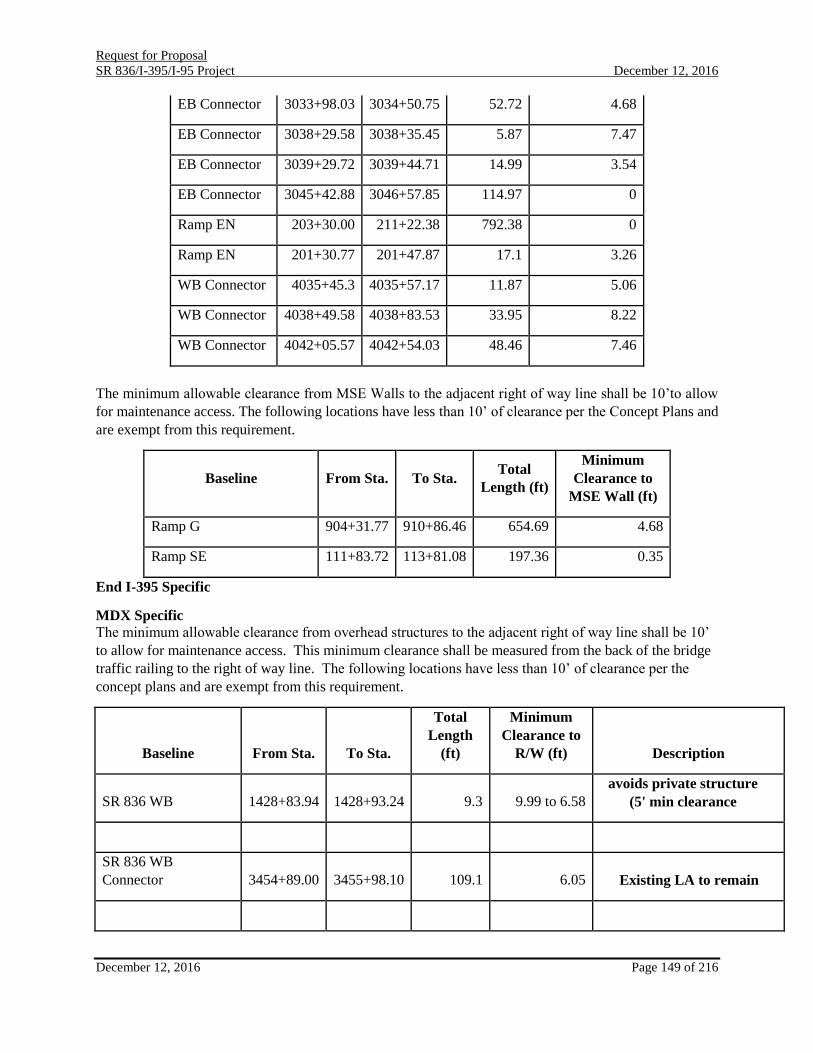
Request for Proposal
SR 836/I-395/I-95 Project December 12, 2016
December 12, 2016 Page 149 of 216
EB Connector 3033+98.03 3034+50.75 52.72 4.68
EB Connector 3038+29.58 3038+35.45 5.87 7.47
EB Connector 3039+29.72 3039+44.71 14.99 3.54
EB Connector 3045+42.88 3046+57.85 114.97 0
Ramp EN 203+30.00 211+22.38 792.38 0
Ramp EN 201+30.77 201+47.87 17.1 3.26
WB Connector 4035+45.3 4035+57.17 11.87 5.06
WB Connector 4038+49.58 4038+83.53 33.95 8.22
WB Connector 4042+05.57 4042+54.03 48.46 7.46
The minimum allowable clearance from MSE Walls to the adjacent right of way line shall be 10’to allow
for maintenance access. The following locations have less than 10’ of clearance per the Concept Plans and
are exempt from this requirement.
Baseline From Sta. To Sta. Total
Length (ft)
Minimum
Clearance to
MSE Wall (ft)
Ramp G 904+31.77 910+86.46 654.69 4.68
Ramp SE 111+83.72 113+81.08 197.36 0.35
End I-395 Specific
MDX Specific
The minimum allowable clearance from overhead structures to the adjacent right of way line shall be 10’
to allow for maintenance access. This minimum clearance shall be measured from the back of the bridge
traffic railing to the right of way line. The following locations have less than 10’ of clearance per the
concept plans and are exempt from this requirement.
Baseline From Sta. To Sta.
Total
Length
(ft)
Minimum
Clearance to
R/W (ft) Description
SR 836 WB 1428+83.94 1428+93.24 9.3 9.99 to 6.58
avoids private structure
(5' min clearance
SR 836 WB
Connector 3454+89.00 3455+98.10 109.1 6.05 Existing LA to remain

Request for Proposal
SR 836/I-395/I-95 Project December 12, 2016
December 12, 2016 Page 150 of 216
SR 836 EB Connector 2415+00.60 2415+16.15 15.55 3.98 to 9.99 within canal
SR 836 EB Connector 2415+53.26 2415+95.06 41.8 3.14 to 3.76 avoids private structure
SR 836 EB Connector 2422+42.50 2425+30.21 287.71 0.2 to 6.35 Fire lane for structure
Ramp I 4477+47.93 4477+92.76 44.83 4.36 to 6.17 avoids private structure
Ramp J 7495+67.78 7495+81.72 13.94 9.62 RFP concept change
In addition, locations where the structures are over local roads are also exempt from this requirement since
only a permit is required from the governing agency.
End MDX Specific
H. Design Documentation, Calculations, and Computations:
The Design-Build Firm shall submit to the Department design documentation, notes, calculations, and
computations to document the design conclusions reached during the development of the construction
plans.
The design notes and computation sheets shall be fully titled, numbered, dated, indexed, and signed by the
designer and the checker. Computer output forms and other oversized sheets shall be folded to a standard
size 8½" x 11". The data shall be in a hard-back folder for submittal to the Department. At the Project
completion, a final set of design notes and computations, signed by the Design-Build Firm, shall be
submitted with the As-Built Plans and tracings.
The design documentation, notes, calculations and computations shall include, but not be limited to the
following data:
1. Design standards and criteria used for the Project
2. Structural design calculations
3. Geometric design calculations for horizontal alignments
4. Vertical geometry calculations
5. Documentation of decisions reached resulting from meetings, telephone
conversations or site visits
I. Structure Plans:
1. Bridge Design Analysis:
The Design-Build Firm shall submit to the Department final signed and sealed design documentation
prepared during the development of the plans.
a. The Design-Build Firm shall insure that the final geotechnical and hydraulic

Request for Proposal
SR 836/I-395/I-95 Project December 12, 2016
December 12, 2016 Page 151 of 216
recommendations and reports required for bridge design are submitted with
the 90% bridge plans.
I-395 Specific
b. All Structures, including the Shared Use Path bridge and MDT Metromover,
Bridge shall meet the “Level Three” Aesthetic Criteria per Plan Preparation
Manual, Volume 1 Section 26.9.4; except bridge spans west of NW 3rd
Avenue.
End I-395 Specific
c. The environmental classification for all bridges except the MacArthur bridge
widening shall be as follows:
Superstructure - Moderately Aggressive
Substructure – Extremely Aggressive
d. The environmental classification for the MacArthur bridge widening shall be
as follows:
Superstructure - Extremely Aggressive
e. The Design-Build Firm shall "Load Rate" all bridges in accordance with the
Department Procedure 850-010-035 and the Structures Manual. The Bridge
Load Rating Calculations, the Completed Bridge Load Rating Summary Detail
Sheet, and the Load Rating Summary Form shall be submitted to the
Department for review with the 90% superstructure submittal. The final Bridge
Load Rating Summary Sheet and Load Rating Summary Form shall be
submitted to the Department for review with the Final superstructure submittal.
A final, signed and sealed Bridge Load Rating, updated for as-built conditions,
shall be submitted to the Department for each phase of the bridge construction
prior to placing traffic on the completed phase of the bridge. A final, signed and
sealed Bridge Load Rating, updated for the as-built conditions as part of the As-
Built Plans submittal shall be submitted to the Department before any traffic is
placed on the bridge. The Bridge Load Rating shall be signed and sealed by a
Professional Engineer licensed in the State of Florida.
I-395 Specific
f. For any approved arch Signature Bridge Option, the Design-Build Firm shall
"Load Rate" the arch component as well as the superstructure components in
accordance with the Department Procedure 850-010-035 and the Structures
Manual.
End I-395 Specific
g. The Design-Build Firm shall evaluate scour on all bridges over water using the
procedures described in HEC 18. h. Any erection, demolition, and any proposed sheeting and/or shoring plans that
may potentially impact the railroad must be submitted to and approved by the
railroad. This applies to areas adjacent to, within and over railroad rights of
ways.
i. The Engineer of Record for bridges shall analyze the effects of the construction

Request for Proposal
SR 836/I-395/I-95 Project December 12, 2016
December 12, 2016 Page 152 of 216
related loads on the permanent structure. These effects include but are not
limited to: construction equipment loads, change in segment length, change
in construction sequence, etc. The Engineer of Record shall review all
Contractor’s Engineer of Record submittals (camber curves, falsework
systems, etc.) to ensure compliance with the contract plan requirements and
intent.
j. I-395 and MDX Specific
Lead and Asbestos
Removal of Existing Structures
In addition to the requirements of Section 110 of the Standard Specifications,
comply with all Federal, State, and Local laws pertaining to work involving safety
and pollution control. This includes but is not limited to the Occupational Safety
and Health Administration (OSHA) Guidelines:
Fact Sheet No. Topic
93-47 Worker Protection
93-48 Engineering Controls
93-49 Housekeeping and Personal Hygiene Practices
93-50 Protective Clothing
93-51 Respirator Protection
93-52 Medical Surveillance
This also includes but is not limited to the following provisions of the Code of
Federal Regulation and all requirements contained in the Clean Air Act of 1977
and 1990.
CODE OF FEDERAL REGULATIONS
Number Topic
29 CFR 1910 Subpart Q OSHA Welding, Cutting, and Brazing
29 CFR 1910.134 OSHA Respirator Protection
29 CFR 1910.1200 OSHA Hazardous Communication
29 CFR 1926.59 OSHA Hazardous Communication
29 CFR 1926.62 OSHA Lead Exposure in Construction
29 CFR 1926.354 OSHA Welding, Cutting, and Heating in Way of
Preservative Coating
29 CFR 1926.1127 Cadmium
40 CFR 50 National Primary and Secondary Ambient Air
Quality Standards
Appendix B Reference Method for the Determination of Total
Suspended Particulate Matter in the Atmosphere
(High Volume Method)
Appendix G Reference Method for Determination of Lead in
Suspended Particulate Matter collected from
Ambient Air
Appendix J Reference method for Determination of
particulate Matter as PM 10 in the Atmosphere

Request for Proposal
SR 836/I-395/I-95 Project December 12, 2016
December 12, 2016 Page 153 of 216
(High Volume Method)
40 CFR 58 EPA Ambient Air Quality Surveillance (PM 10
Monitoring)
40 CFR 122 EPA Administrated Permit Program: The
National Pollutant Discharge Elimination
System
40 CFR 260 through 273 EPA Hazardous Waste Regulations
Additional items the Contractor shall adhere to:
EPA Report No. SW 846. Test Methods for Evaluating Solid Waste Physical/
Chemical Tests
EPA Toxicity Characteristic Leaching Procedure, Test Method 1311 SSPC-SP11
Power Tool Cleaning to Bare Metal
SSPC-Guide 6, Guide for Containing Debris Generated During Paint Removal
Operation
SSPC-Guide 7, Guide for the Disposal of Lead-Contaminated Surface
Preparation Debris
During any burning, torch cutting, or any operation which would cause the existing
paint to be heated above 506°F, the paint shall be vacuum shrouded power tool
cleaned to bare metal (ref. SSPC-SP11) a minimum of 4 inches from the area of
heat application or the employee(s) within the regulated area shall be protected by
supplied air respirators (ref. 29 CFR 1926.354). The Contractor shall refer to
OSHA Lead Exposure in Construction (29 CFR 1926.62) for guidance.
Disposal Disposal of materials shall be in accordance with Section 110 of the Standard
Specifications.
Refer to Reference Document RD-02 for Lead and Asbestos reports.
End I-395 and MDX Specific
2. Criteria
The Design-Build Firm shall incorporate the following into the design of this facility:
a. Bridge Widening: In general, match the existing as per the Department Structures
Manual.
b. Critical Temporary Retaining Walls: Whenever the construction of a component
requires excavation that may endanger the public or an existing structure that is in
use the Design-Build Firm must protect the existing facility and the public. If a
critical temporary retaining wall is, therefore, required during the construction
stage only, it may be removed and reused after completion of the work. Such
systems as steel sheet pilings, soldier beams and lagging or other similar systems
are commonly used. In such cases, the Design-Build Firm is responsible for
designing detailing the wall in the set of contract plans. These plans must be signed
and sealed by the Structural Engineer in responsible charge of the wall design.

Request for Proposal
SR 836/I-395/I-95 Project December 12, 2016
December 12, 2016 Page 154 of 216
c. Except for the bridges below; all other new bridge structures including the widened
bridges shall be classified based on its operational importance as “typical” bridges
(=1.0) in accordance with SDG 2.10.B.
I-395 Specific
Bridges 1, 2, 3, 4, 5, 6, 7, 8, 9, 10, 11, 12, and 13 shall be classified as
“essential” in operational importance and use I = 1.05 for the strength limit
state and I = 1.0 for all other limit states in accordance with AASHTO 1.3.5.
End I-395 Specific
d. All bridge drainage conveyance shall be piped inside piers to the proposed
drainage system.
e. For bridges over navigable waterways:
I-395 Specific The superstructure widening on MacArthur Causeway is exempt from establishing
the required pier strength for minimum vessel collision. End I-395 Specific MDX Specific
For Bridge No’s 870147 and 870298, spanning over the Miami River, Pier No 15
and 16 shall be designed for a minimum vessel collision force of 140 kips.
Bridge No’s 870147 and 870298 shall remain two separate bridges. End MDX Specific f. All structures shall be new unless otherwise specified.
g. Design and detail all concrete box girder top slabs and longitudinal closure pours
between box girders to be transversely port-tensioned. Reduce critical eccentricities over the webs, and at or near the center of each cell within the box and longitudinal closure pour between box girders, from theoretical to account for the tendon profile within the duct and by an additional 1/4 – inch from theoretical to account for construction tolerances. Utilize a combination of mild reinforcing and transverse continuity post-tensioning through all longitudinal closure pours and provide a mild reinforcing connection between the tip of segment wings and closure pour. The tensile stress of the mild reinforcing steel in the connection shall be limited to 0.5 fy under Service Limit State.
h. Full depth precast deck panels are not allowed.
i. Where precast short-line match-casting is utilized, provide steam curing of both
the match-cast (conjugate) segment and segment being cast for segments meeting both criteria listed below.
a. When segments are wider than 50 ft. b. when the segment width-to-segment-length is equal to or greater than 5.0
j. In the Casting Manual, the Design Build Firm may propose an alternate plan to
steam curing to address the potential for thermal gradient warping of the match-cast surfaces.
3. General Design Requirements
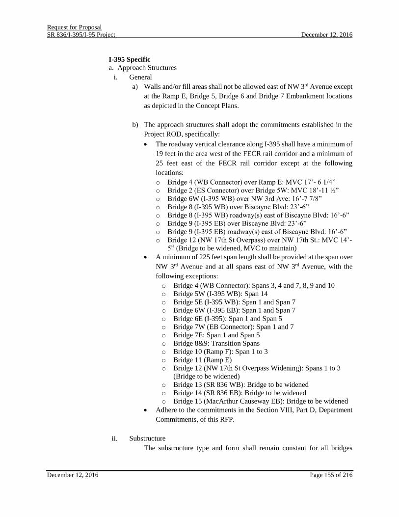
Request for Proposal
SR 836/I-395/I-95 Project December 12, 2016
December 12, 2016 Page 155 of 216
I-395 Specific a. Approach Structures
i. General
a) Walls and/or fill areas shall not be allowed east of NW 3rd Avenue except
at the Ramp E, Bridge 5, Bridge 6 and Bridge 7 Embankment locations
as depicted in the Concept Plans.
b) The approach structures shall adopt the commitments established in the
Project ROD, specifically:
The roadway vertical clearance along I-395 shall have a minimum of
19 feet in the area west of the FECR rail corridor and a minimum of
25 feet east of the FECR rail corridor except at the following
locations:
o Bridge 4 (WB Connector) over Ramp E: MVC 17’- 6 1/4”
o Bridge 2 (ES Connector) over Bridge 5W: MVC 18’-11 ½”
o Bridge 6W (I-395 WB) over NW 3rd Ave: 16’-7 7/8”
o Bridge 8 (I-395 WB) over Biscayne Blvd: 23’-6”
o Bridge 8 (I-395 WB) roadway(s) east of Biscayne Blvd: 16’-6”
o Bridge 9 (I-395 EB) over Biscayne Blvd: 23’-6”
o Bridge 9 (I-395 EB) roadway(s) east of Biscayne Blvd: 16’-6”
o Bridge 12 (NW 17th St Overpass) over NW 17th St.: MVC 14’-
5” (Bridge to be widened, MVC to maintain)
A minimum of 225 feet span length shall be provided at the span over
NW 3rd Avenue and at all spans east of NW 3rd Avenue, with the
following exceptions:
o Bridge 4 (WB Connector): Spans 3, 4 and 7, 8, 9 and 10
o Bridge 5W (I-395 WB): Span 14
o Bridge 5E (I-395 WB): Span 1 and Span 7
o Bridge 6W (I-395 EB): Span 1 and Span 7
o Bridge 6E (I-395): Span 1 and Span 5
o Bridge 7W (EB Connector): Span 1 and 7
o Bridge 7E: Span 1 and Span 5
o Bridge 8&9: Transition Spans
o Bridge 10 (Ramp F): Span 1 to 3
o Bridge 11 (Ramp E)
o Bridge 12 (NW 17th St Overpass Widening): Spans 1 to 3
(Bridge to be widened)
o Bridge 13 (SR 836 WB): Bridge to be widened
o Bridge 14 (SR 836 EB): Bridge to be widened
o Bridge 15 (MacArthur Causeway EB): Bridge to be widened
Adhere to the commitments in the Section VIII, Part D, Department
Commitments, of this RFP.
ii. Substructure
The substructure type and form shall remain constant for all bridges

Request for Proposal
SR 836/I-395/I-95 Project December 12, 2016
December 12, 2016 Page 156 of 216
located east of NW 3rd Avenue and shall match the Concept Plans and
Aesthetics Manual. For the concrete box option, the pier head width shall
match the box girder soffit width except where specifically allowed in
Figure 5-8 of the project Bridge Development Report. For either the
concrete box or steel box options, the pier locations shall match the
Concept Plans +/- 3’. In no case shall the required clearances be violated.
a) No straddle bents shall be used, except at Ramp B and Ramp C gore areas
and where WB connector splits into EN and ES connectors. In order to
accommodate a re-alignment of NW 13th St, a straddle bent may be used
at the WB connector at Ramp F gore to span over NW 13th St.
c) The use of hammerhead piers shall be limited to the west of NW 3rd Ave.
d) For all piers east of NW 3rd Avenue, pier locations shall match locations
depicted in the Concept Plans.
e) For piers east of NW 3rd Avenue, all piers shall match the pier shapes
depicted in the Concept Plans and Aesthetics Manual.
iii. Superstructure
a) The superstructure type and material shall remain the same throughout
each bridge, as follows:
Description Required Structure Type
Bridge 1 EN Connector Steel Plate or Steel Box Girder
Bridge 2 ES Connector Steel Plate or Steel Box Girder
Bridge 3 SE Connector Steel Plate or Steel Box Girder
Bridge 4 WB Connector
Precast or CIP Concrete Segmental
Box or Steel Box Girder
Bridge 5W
I-395 WB
Precast and CIP Concrete
Segmental Box or Steel Box Girder;
*Spans 1 to 7 FIB Girder
Bridge 5E I-395 WB
Precast and CIP Concrete Segmental
Box or Steel Box Girder
Bridge 6W I-395 EB
Precast and CIP Concrete Segmental
Box or Steel Box Girder
Bridge 6E I-395 EB
Precast and CIP Concrete Segmental
Box or Steel Box Girder
Bridge 7W EB Connector
Precast and CIP Concrete Segmental
Box or Steel Box Girder
Bridge 7E EB Connector
Precast and CIP Concrete Segmental
Box or Steel Box Girder
Bridge 10 Ramp F
Precast and CIP Concrete Segmental
Box or Steel Box Girder
Bridge 11 Ramp E
Precast and CIP Concrete Segmental
Box or Steel Box Girder
Bridge 12 NW 17th St Overpass Widening FIB (modified) / AASHTO Girder
Bridge 13 SR 836 WB Widening *FIB (modified) and Steel Plate

Request for Proposal
SR 836/I-395/I-95 Project December 12, 2016
December 12, 2016 Page 157 of 216
Bridge 14 SR 836 EB Widening FIB (modified) and Steel Plate
Bridge 15 Macarthur Causeway Widening FIB (modified) / AASHTO Girder
* Reference latest Typical Section Package for updated bridge limits.
b) Bridge No. 1 and 2 shall be of the same type and material.
c) Bridge Nos. 4, 5E, 5W, 6E, 6W, 7E, 7W, 10 and 11 shall be of the same
material (e.g., concrete or steel).
d) For the steel box girders, integral diaphragms at piers shall be used.
e) Permanent intermediate diaphragms shall not be permitted for the steel
box option for Bridge Nos. 4, 5E, 5W, 6E, 6W, 7E, 7W, 10 and 11;
however, full depth diaphragms at inflection points where a girder line is
introduced are allowed. Steel boxes may utilize temporary external
diaphragms; however, connection plates shall be bolted and removed
from the permanent structure. All unused holes after connection plate
removal shall be filled with bolts.
f) Cheek Walls shall be required at all piers and end bents for Bridge Nos.
1 and 2.
g) The number of box girders to be used is limited as follows:
Bridge Concrete Box Steel Box
4 maximum of 1
except for spans
adjacent to the
gores
maximum of 4 Span 1, maximum
of 3 Spans 2 - 9, maximum 2
Spans 10 - 13
5E maximum of 2
except for span
adjacent to the gore
maximum of 3 Spans 1 – 3,
maximum 5 Spans 4 & 5,
maximum 4 Spans 6 & 7
5W
maximum of 2
except for span
adjacent to the gore
maximum of 3 Spans 1 – 10, 13
& 14, maximum 4 Spans 11 & 12
6E maximum of 2
except for span
adjacent to the gore
maximum of 3 Spans 1 – 5,
maximum 5 Span 6, maximum 3
Span 7
6W maximum of 2
except for 2 spans
adjacent to the gore
maximum of 4 Spans 1 – 5,
maximum 3 Spans 6 & 7
7E maximum of 1 maximum of 2
7W maximum of 1
except for span
adjacent to the gore
maximum of 3 Spans 1 – 5,
maximum 2 Spans 6 & 7
10 maximum of 1 maximum of 2
11 maximum of 1 maximum of 2

Request for Proposal
SR 836/I-395/I-95 Project December 12, 2016
December 12, 2016 Page 158 of 216
Ramps B & C maximum of 2 maximum of 2
h) For all bridges except for Signature Bridges, constant-depth and variable
depth girders are acceptable. Parallel bridges shall maintain either
constant-depth or variable depth girders across the corridor section;
mixed girder types (e.g., constant depth versus variable depth) across a
section are not allowed.
i) For Bridges 4, 5E-7E, 5W-7W, 10 and 11 concrete box girder web slopes
shall be maintained at 1H:2.5V except for the Transition Span which
occurs between the approach structures and the west end of the Signature
Bridge superstructure. Steel box girder web slopes shall be maintained at
1H:4V throughout the corridor.
j) A smooth transition shall be maintained between the approach viaduct
superstructure and the superstructure of the Signature Bridge span.
k) No vertical steps are allowed between adjacent superstructure units east
of NW 3rd Avenue.
l) Horizontal offsets of the fascia web of the Exterior Box, are not allowed.
This shall be applicable to the box girders located to the east of NW 3rd
Ave.
m) Exterior Box is defined as the outer two box girders in a bridge typical
section of three or more box girders; and all box girders in a bridge typical
section of one or two box girders.
n) New and widened bridges shall use 32” F-shape traffic railings except the
following shall have a 42” F-shape traffic railing:
Bridges and retaining wall sections where the horizontal curve
radius is 900-ft. or less.
Bridge 13 right and left railing
Bridge 14 right railing
Bridge 5W west of 3rd Avenue left railing
b. Signature Bridge Criteria
The Design-Build Firm shall design and construct the Signature Bridge in accordance with the criteria
established herein. Sample design concepts are described in the Attachments and Reference Documents.
Minimum requirements include:
i. Signature Bridge materials, details and design features which extend the service life beyond 75
years are encouraged. It is also encouraged to provide replaceable structural components with a
design life track record that minimizes the number of times the component needs to be replaced.
The following replaceable non-standard bridge components shall also be designed for replacement:
Stay Cables/Suspenders and Tie-down Cables; Stay Cable Dampers; and External Post-Tensioning
Cables.
ii. The Signature Bridge and Transition Spans shall match the visual appearance of Approved
Signature Bridge Package. Changes to Approved Signature Bridge Package that affects the visual
appearance of the structure in any way shall not be permitted. The Department reserves the right

Request for Proposal
SR 836/I-395/I-95 Project December 12, 2016
December 12, 2016 Page 159 of 216
to deem a Design-Build Firm non-responsive for changes made to the Approved Signature Bridge
Package or an approved ATC Signature Bridge Package.
iii. The horizontal and vertical transition from the Approach Spans to the Signature Bridge shall occur
in the Transition Spans.
iv. The Signature Bridge shall satisfy the commitments established in the Project ROD.
v. The Signature Bridge deck shall be cast-in-place concrete deck with an 8 ½ inch minimum
thickness to accommodate planning and profilographing (1/2 inch sacrificial concrete cover) and
machine grooving in accordance with Long Bridge Class 4 Deck Finish criteria.
vi. Adhere to the requirements in the Aesthetics Manual, Attachment A-18.
vii. All Signature Bridge components shall be part of the structural system that carries bridge Dead
Load (DL) and Live Load (LL); no non-structural bridge components will be accepted.
viii. The Signature Bridge shall span Biscayne Boulevard, linking the approach structures with the
embankments east of Biscayne Boulevard.
ix. The Signature Bridge shall be designed to carry both westbound (WB) and eastbound (EB)
roadways.
x. Piers shall match the pier shapes depicted in the Concept Plans and Aesthetics Manual.
xi. A smooth transition shall be maintained between the approach viaduct superstructure and the
superstructure of the Signature Bridge. At the Transition-Span-to-Signature Bridge interface and at
the Transition-Span-to-typical-approach span interface maintain web slopes without horizontal off-
sets or vertical steps.
xii. Girder depth on each side of the expansion joints shall be the same, i.e., no steps allowed.
xiii. Horizontal offsets of the fascia web of the Exterior Box, as defined above, are not allowed.
xiv. The Signature Bridge design shall conform to the following parameters:
a) Minimum apex of the structure shall be above El. 245 ft.
b) Minimum height of highest cable attachment to pylon/arch is 190 ft. or arch is El. 236 ft.
c) Except as defined below, the Signature Bridge (west expansion joint to abutment) shall
consist of a single span not less than 650-ft. long with a total suspended length (clear distance
measured between the first and last suspender along center line of deck) not less than 500-ft.
d) For cable stayed bridge options, the Signature Bridge (west expansion joint to abutment)
shall consist of no more than three spans with a total length of 650-ft. with two suspended
spans with a total suspended length (clear distance measured between the first and last
suspender along center line of deck) not less than 500-ft. The longitudinal framing elements
for all spans shall be consistent throughout.
xv. Provide a Signature Bridge Health Monitoring System per the requirements of Attachment A-28.
xvi. Provide a Signature Bridge Inspection and Maintenance Manual per the requirements of
Attachment A-26.
c. Bridge Widening Structure
Bridge Widening at MacArthur Causeway Bridge (Bridge 15), SR 836 (Bridges 13 and 14) and NW 17th
St. (Bridge 12) shall match the existing. The following shall be adhered to:
i. The span configuration (i.e., simple span or continuous span) shall match the existing
superstructure.
ii. All widened spans with AASHTO beams or FIBs may utilize precast girder type to match the

Request for Proposal
SR 836/I-395/I-95 Project December 12, 2016
December 12, 2016 Page 160 of 216
existing bridge girder.
iii. For the widenings at SR 836 and NW 17th St., the substructure for the widened portion of the
existing bridges shall match the existing substructures, new columns shall be aligned with the
existing where possible, same column and bent geometry and shape.
iv. MacArthur Causeway Bridge Cross Slope Correction: Hydro-blast existing deck ¾” below the top
mat of deck steel and construct new concrete overlay build-up. See Concept Plans for limits of
the Hydro-blasting and deck reconfiguration. Finish the widened/slope corrected portion of the
deck surface utilizing Short Bridge Class 4 Deck Finish criteria.
v. Class 5 Finish Coating shall be applied to the exterior fascia girders, traffic railing barriers and
soffits of the widened bridge. For the widenings at SR 836 and NW 17th St., apply Class 5 Finish
Coating to all exposed surfaces of the pier for the widened portion.
vi. Existing Aesthetic Lighting on the MacArthur Bridge piers shall be protected.
d. Shared Use Path bridge
The Shared Use Path bridge shall be located within the existing FDOT right-of-way which includes the
aerial easement over the FECR. The Shared Use Path bridge shall provide a minimum clear width of 12’
and a minimum vertical clearance of 8’ above the deck of the Shared Use Path bridge. The Shared Used
Path bridge shall meet the minimum vertical clearance over FECR described in Section IX, Part F,
Railroad/Transit Accommodations, in this RFP. The Shared Use Path bridge shall provide an integrated
and logical connection for pedestrians and bicyclists between the streetscape and the bridge. The bridge
shall be designed in accordance with SDG 10.4. Provide full screening over the FECR right-of-way and
partial screening on all areas outside of the FERC right-of-way. Location, design and construction of the
structure shall be such that it will not require modification of the current Right-of-Way documents and/or
the FECR Perpetual Aerial Easement Agreement (See Attachment A-16 FECR Requirements and
Attachment A-39 Right of Way – Survey). The Design-Build Firms shall not coordinate with FECR to
modify the current FECR Perpetual Aerial Easement Agreement (See Attachment A-16: FECR
Requirements).
e. MetroMover Bridge Reconstruction
All plans and designs are to be prepared in accordance with AASHTO LFD Bridge Design Specifications,
FDOT Standard Specifications, Miami Metromover Brickell Extension, Basis for Design, December 1989,
FDOT Structures Manual, FDOT Plans Preparation Manual, FDOT Standard Drawings, Supplemental
Specifications, Special Provisions, FDOT Temporary Design Bulletins, and the Florida Building Code
2010. Design bridge retrofit in accordance with the latest AASHTO LFD Bridge Design Specifications
utilizing the loads and loads cases depicted in the Miami Metromover Brickell Extension, Basis for Design,
December 1989.
The Design-Build Firm shall be in compliance with the current MDT Safety Certification Program Plan
and the MDT Adjacent Construction Safety Manual. A Safety Certification will be required with the
proposed modifications to the MDT Metromover System.
The existing minimum vertical clearance of Pier P239680B shall be maintained. The new column shall be
rectangular, or square, with corner filets that match the radius of the adjacent existing Metromover Bridge
columns.

Request for Proposal
SR 836/I-395/I-95 Project December 12, 2016
December 12, 2016 Page 161 of 216
Only deep foundations will be approved for the pier replacement.
The Design-Build Firm shall ensure that the final geotechnical report required for design are submitted
with the 90% structures plans.
The Engineer of Record for structures shall analyze the effects of the construction related loads on the
existing and permanent structure. These effects include but are not limited to: construction equipment
loads, jacking loads, construction sequence, structure demolition, etc. The Engineer of Record shall
review all Contractor’s Engineer of Record submittals (falseworks systems, etc.) to ensure compliance
with the contract plan requirements and intent.
A Class 5 Surface Finish shall be applied to all exposed surfaces of the pier, except top of cap. A non-
sacrificial anti-graffiti coating shall also be applied to the pier column to a height of 10 feet.
Proper disposal of the existing structure components shall be the responsibility of the Design-Build Firm.
Proposed piers for Metromover Bridge shall be properly protected from damage by installing proper
protection. A study indicating possible vehicle impact, maximum speed limit in the area, calculations and
recommendations for the protection system are to be submitted to MDT for review and approval prior to
installation. Since this is a safety component, it is expected to be installed and fully functional concurrent
with column base construction.
Girder deflections shall not exceed the limits specified in the design criteria. The design shall ensure that
the girder movements at bearings and clearance gaps do not exceed available capacity.
The Design-Build Firm shall provide primary and secondary protection systems for the Department’s
review and approval to capture construction related materials and equipment and to allow the Metromover
system to operate.
Continuous grounding for the guideway’s lightning protection and stray current grounding systems shall
be maintained. The proposed bridge shall be properly grounded and shall have a lightning protection system
that is independent of the guideway’s electrical systems.
The Design-Build Firm shall continuously monitor and survey the elevations and deflections of the existing
Metromover aerial guideway affected by the proposed construction and shall ensure that these deflections
are within acceptable limits approved by MDT. Any temporary supports, shoring, and/or construction
activities affecting the aerial guideway during construction shall not adversely affect operational
requirements of the Metromover system. This includes, but not limited to, stress limits, deflection limits,
and rider comport. The Metromover system and equipment are extremely sensitive; therefore, the final
position of all components of the Metromover aerial guideway, after construction, shall be at the same
position as before construction. A detailed Jacking Plan shall be developed by the Design-Build Firm and
submitted for approval with the 90% Plans submittal.
A portion of the existing bent is to be demolished as part of the scope of work for this project. See Section
I.15.c., “Demolition,” for requirements during demolition.
The Design-Build Firm must provide training to the MDT inspection staff and must provide inspection
manuals (hard copies and electronic formats). The Design-Build Firm shall conduct the initial bridge
inspection for the Metromover Bridge span.

Request for Proposal
SR 836/I-395/I-95 Project December 12, 2016
December 12, 2016 Page 162 of 216
f. Retaining Walls
i. Partial height walls such as toe walls or perched walls as defined in FDOT Structural Design
Guidelines 3.12.B shall not be allowed.
ii. For color, and texture and architectural features for retaining walls, see I-395 Aesthetic
Requirements.
iii. Wall/fill heights shall not exceed 40’ ft.
iv. Sloped embankments are not allowed.
End I-395 Specific
MDX Specific
General Design Requirements
1. Bridges
a. Superstructure:
i. The widening or the replacement of the existing bridge slabs shall use similar
material as the existing superstructure. For the existing steel plate girder bridge
structures, the same type shall be used. For the existing AASHTO beam bridge
structures, AASHTO beams or Florida I-Beams (FIB) shall be used.
Grooving: For bridges to be widened, the minimum slab thickness shall
not be less than 8 inches at the existing bridge interface, tapered to not less
than 8 ½ inches at the first beam-line. All remaining portions of the
widened deck shall not to be less than 8 ½ inches. The widened deck
surfaces shall be planed and profilographed and machined grooved in
accordance with Long Bridge Class 4 Deck Finish criteria.
ii. The allowable Superstructure Types for new bridges are:
Steel Box Girder
Spliced U-Girder
Florida U-Beam
Florida I-Beam
Steel Plate Girder
Segmental Box Girder
The superstructure type and material shall remain the same throughout the specified
limits for the following Bridges:
BRIDGE-17, Spans 3 through 13
BRIDGE-18
BRIDGE-19
BRIDGE-22, Spans 3 through 5
BRIDGE-23
BRIDGE-24
b. Substructure:

Request for Proposal
SR 836/I-395/I-95 Project December 12, 2016
December 12, 2016 Page 163 of 216
i. The substructure for the widened portion of the existing bridges shall be aligned
with the existing columns. The substructure shall have the same column and bent
geometry and shape with the exception of the following:
Bridge 870147 - Piers 10, 11, 12, and 13
Bridge 870298 – Piers 10, 11, and 12
Bridge 870456 – Piers 2, 3, 4, and 5
Bridge 870724 – Piers 7 and 8
ii. The substructure for the new bridges located between NW 17th Avenue and west
of NW 7th Avenue shall be hammerheads, C-Piers or straddle bents. Intermediate
pile bents are not accepted. Substructure shall meet MDX Enhancement Manual
requirement for aesthetics.
iii. The substructure for the new bridges Nos. 20 and 21 shall match in type the
substructure for the new bridges Nos. 1 and 2 for the I-395 Reconstruction
Project.
iv. Cheek Walls shall be provided at substructure expansion joints and end bents for
all new structures.
v. For Bridge No. 870456 (SR 836 EB), at the Women’s Correction Facility between
Station 1477+30.76 (Pier 2) and Station 1479+32.59 (Pier 5), the substructure
shall consist of straddle bent, providing 40’ clear distance between the columns
in order to allow full access to the parking facility
c. General:
i. Additional improvements:
a) Remove and replace a portion of existing superstructure as necessary to
address cross slope and geometry requirements due to widening. Refer
to reference documents MDRXD-01 for locations.
ii. Bridge Fencing: Fencing as per FDOT Standard Index 810 shall be installed along
the bridge traffic railings at the following locations:
a) Along Bridge No. 870147, from mainline SR 836 station 1429+00 to
station 1434+00, on the north side (outside shoulder traffic railing).
b) Along Bridge No. 870298, from mainline station 1428+00 to station
1432+00, on the south side (outside shoulder traffic railing).
c) Along Bridge No. 24, located at the crossing over the Metrorail, along
both sides. Extend the fence 25 feet before and after the Metrorail
footprint.
iii. Bridge Traffic Railing:
a) The traffic railings for the existing bridges within the MDX Project
limits shall be upgraded to F-Shape traffic railings with the specified
heights from the table below.
b) New Bridges shall use F-shape traffic railings with the specified heights
from the table below.
Bridge Traffic Railing (Looking Upstation)

Request for Proposal
SR 836/I-395/I-95 Project December 12, 2016
December 12, 2016 Page 164 of 216
iv. Bridge Expansion Joints: All the bridge joints for the existing bridges within the
MDX Project limits shall be replaced. For the existing bridges located partially
within the MDX Project limits (Bridge Nos. 870363, 870397, 870370, and
870724), only the sections within the MDX Project limits will require expansion
joint replacement, inclusive of the joints at the end of the MDX Project limits.
For Bridge Nos. 870456 and 870366, the joint replacement shall be for the entire
bridge lengths, from begin to end of bridge.
EXPANSION JOINT SUMMARY
BRIDGE NO. DESCRIPTION
NO. OF POURED
JOINTS WITH
BACKER ROD
JOINTS
NO. OF ARMORED
ELASTOMERIC
STRIP JOINTS
870147 SR 836 WB 27 2
870298 SR 836 EB 27 2
BRIDGE NO. Left Railing (in) Right Railing (in)
16 32 32
17 42 42
18 42 42
19 42 42
20 42 42
21 42 42
22 42 42
23 42 42
24 42 42
870147 42 32
870298 32 42
870150 42 32
870300 32 42
870366 42 42
870456 32 42
870363 32 32
870364 32 32
870367 42 42
870370 32 32
870724 42 42

Request for Proposal
SR 836/I-395/I-95 Project December 12, 2016
December 12, 2016 Page 165 of 216
870150 SR 836 WB 4 2
870300 SR 836 EB 6 2
870366 SR 836 WB 10 N/A
870456 SR 836 EB 13 N/A
870363 SR 836 WB
CONNECTOR 3 N/A
870367 SR 836 E-S
CONNECTOR 10 N/A
870370 SR 836 E-N
CONNECTOR N/A 4
870724 RAMP J/ RAMP
L 8 3
v. Painting:
The existing, the widened, and the new steel bridges shall be painted with High
Performance Coating System from the Approved Products List. Paint color shall
be as per the MDX Enhancement Manual. All existing steel bearings shall be
cleaned, dirt shall be removed from the surrounding area and the complete anchor
assembly shall be cleaned, rust removed and painted with the same color and
coating system as the bridge.
vi. Bridge Aesthetics:
a) The new bridges located between NW 17th Avenue and west of NW 7th
Avenue shall meet the “Miami Dade Expressway Enhancement Manual”
aesthetic level.
b) The new bridges between NW 7th Avenue and the interface with I-395
Reconstruction Project shall meet the “Level Two” aesthetic criteria per
FDOT Plan Preparation Manual, Volume 1, Section 26.9.4.
c) All existing bridges widened or retrofitted shall use similar material as
the existing and matching the current level of aesthetic on the bridge.
d) Class 5 Finish Coating shall be applied to the exterior fascia girders,
traffic railing barriers and soffits of the widened portion of the bridge.
vii. Grove Park Historic District:
Due the presence of historic homes and the proximity of bridges to these homes,
the following commitment during the Re-evaluation shall be adhered to:
1. New piers closer to the homes than where the existing piers are shall not be
allowed. New piers at the same location of the existing piers and/or
strengthened piers shall be allowed as shown on the structural Concept Plans
found under MDXRD-01.
2. Do not enlarge existing columns such that the diameter exceeds 12’.
These restrictions apply to the following locations:
Bridge No. 870147, SR 836 WB Piers 10, 11, 12 and 13.
Bridge No. 870298, SR 836 EB Piers 10, 11 and 12.
viii. Fender System:

Request for Proposal
SR 836/I-395/I-95 Project December 12, 2016
December 12, 2016 Page 166 of 216
The existing fender system and fender mounted navigation lights located under the
existing bridge Nos. 870147 and 870298 along the Miami River shall be
completely removed and replaced using the latest FDOT New Fender System and
Navigation Lighting criteria. The horizontal clearance of 75 feet shall be
maintained.
Use Fiber Reinforced Polymer (FRP) Composites for all wales, piles, spacer
blocks, catwalk and handrail components.
ix. Wagner Creek Culvert:
The Wagner Creek Culvert shall not be extended. The SR 836 Eastbound
Connector bridge shall be extended over the creek.
x. Retaining Walls:
Partial height walls such as toe walls or perched walls as defined in FDOT
Structural Design Guidelines 3.12.B are not permitted.
For walls between NW 17th Avenue and west of NW 7th street, see MDX
Enhancement Manual for color, texture and architectural features.
For walls between NW 7th Avenue and the interface with I-395 and I-95,
see I-395 Aesthetic Requirements for color, texture and architectural
features.
Wall/fill heights shall not exceed 40 ft.
xi. Seawall:
A portion of the existing seawall located on the west side of the Miami River
(Grove Park Area) will be impacted by the widening of the existing SR 836 bridge
widening. The removal of existing seawalls or soil retaining structures will
require the stabilization of the upland fill by re-grading and slope protection or
the replacement of the seawall or soil retaining structure. End MDX Specific
Begin I-395 Specific
4. Signature Bridge Components
a. Lightning Protection
Lightning protection for the Signature Bridge elements and other elements as required shall be provided
per fib Recommendations for the Acceptance of Stay Cable Systems Using Prestressing Steels (Art 3.3.2
of bulletin 30), NFPA 70 (National Electric code) and NFPA 780.
b. Suspender / Stay Cable System
The cable suspender/stay system shall be in accordance with Attachment A-19, Cable Stay Systems. The
fire resistance requirements shall conform to PTI Section 4.5 – Fire resistance qualification testing for a
thirty (30) minute rating.
5. Signature Bridge Design Parameters:
a. General
i. The distribution of force effects to the components of the Signature Bridge shall
be determined by three dimensional structural analysis as justified by
consideration of principal support element geometry, number of planes of cables,

Request for Proposal
SR 836/I-395/I-95 Project December 12, 2016
December 12, 2016 Page 167 of 216
and the torsional stiffness of the deck superstructure. The analysis shall take into
account consider construction phasing and erection sequences.
ii. Non-linear effects shall be considered in both the global and local analyses of the
structural bridge system.
iii. The design forces and deformations shall include but not be limited to the
following:
a) Non-linear response of the suspenders/cables;
b) The geometric non-linearity of the girder under axial load and bending;
c) The p-delta effect of the principal support elements under axial load and
bending; effects of foundation lateral movements;
d) The non-linear effect of live load that includes the moment due to dead
load thrust acting on the live load displacement;
e) Material nonlinearity;
f) Foundation flexibility.
b. Superstructure Design
The effective width of deck slab for analysis and for calculation of section capacity and stresses shall be
determined by special elastic analysis that considers shear lag effects. Stresses in the deck slab shall be
investigated for the combined effects of longitudinal global axial loads and bending moment plus transverse
local bending moment.
Orthotropic steel deck shall not be used.
Influence surfaces or other similar analysis procedures shall be used to evaluate live load plus impact
effects.
i. Composite Steel Superstructures
Steel tub girders and required framing shall be designed compositely with the deck slab to resist the local
and global bending moments from dead and live loads as well as the compression force from inclined
cables.
ii. Redundancy
Designate both Fracture Critical Members and Structural Redundant Members on the plans.
Steel structures shall be designed to provide structural redundancy and an alternative load path or otherwise
designated as Fracture Critical Members. A refined analysis shall demonstrate that the structure has
adequate strength and stability to avoid partial or total collapse and carry traffic in the presence of a totally
fractured member for all designs not labeled as fracture critical.
Signature Bridge girders shall all be fabricated according to the Fracture Control Plan. Material testing,
fabrication procedures and inspection with strict shop certifications, collectively designated as a Fracture
Control Plan (FCP), shall meet AASHTO and AWS D1.5 Section 12 requirements for fracture critical
fabrication. Structural Redundant Members (SRM) are also structural members that shall be fabricated
according to the FCP, but need not be considered a FCM for in-service inspection due to structural
redundancy. SRMs shall be designated on the Final Design plans with the note to fabricate them in
accordance with the FCP. Shop Drawings shall note that the SRM was fabricated according to the FCP.

Request for Proposal
SR 836/I-395/I-95 Project December 12, 2016
December 12, 2016 Page 168 of 216
The criteria, assumptions, and analysis used to determine the system redundancy condition for a SRM shall
be retained and included in inspection records and the permanent bridge design file. Stay cable anchorage
materials and connection details with the Main Bridge superstructure shall minimize fracture critical details
and the potential for crack propagation.
6. Bridge Design Loads:
a. Load Combinations
Load combinations shall be per AASHTO LRFD Bridge Design Specifications 3.4.1. The bridge shall be
designed with an operational importance factor of 1.05.
The effects of cable stay force adjustments shall be treated as locked-in erection stresses.
Crack Control in Mildly Reinforced Concrete Components: Limit service tension stresses in the outer layer
of longitudinal reinforcing steel for all mildly reinforced arches, pylons, stay towers under Service III
Loading using a e = 0.6 (AASHTO 5.7.3.4).
b. Wind Loads – Signature Bridge
The Design-Build Firm shall prepare a site-specific Climatology and Wind Report in order to generate site
specific wind climate data obtained from analysis of long-term wind data available from reliable data
sources in the area. The site-specific climate properties shall be compared with information in codified
sources to determine the appropriate levels of design wind speed for site location, topography, and local
conditions. This report shall discuss the criteria, analysis, and design methodologies for determining the
appropriate wind design loads for service and construction and ensure aerodynamic stability. The
Climatology and Wind Report shall include the following items at a minimum:
i. A wind study that includes:
a) Gust speeds and return period for the site
b) Extreme wind events for construction
c) Design wind directionality and distribution
d) Design wind speeds for the complete structure and during construction at
the deck level and along the height of structural support elements. The
design shall account for the urban setting that will exist at the proposed
time of completion of the Total Project.
ii. A wind tunnel testing program that describes the testing program and procedures
and local effects on design wind speeds and turbulence.
iii. Design methodologies including:
a) Design codes;
b) Wind design speeds and pressures;
c) Wind load combinations considering both static and dynamic effects;
d) Aeroelastic phenomena of vortex excitation, galloping, flutter, and
divergence;
e) Computer models used to incorporate the results of the climatology study
and wind tunnel tests.
iv. The mean wind return periods and loads used for the design shall not be less than

Request for Proposal
SR 836/I-395/I-95 Project December 12, 2016
December 12, 2016 Page 169 of 216
the following:
a) Design flutter speed of 10,000-year 10-minute mean speed;
b) Design wind speed for the construction phase shall be no less than 3
second gust for a 20-year return period;
c) Design flutter speed for the construction phase shall be no less than
1,000-year return 10-minute speed.
The Design-Build Firm shall perform a sectional model wind tunnel testing as appropriate to verify
satisfactory performance for aerodynamic stability. A Wind Tunnel Test Report shall be prepared including
the following items:
1) Section model testing information stating objectives, criteria, wind tunnel test
procedures, and model description. Also include proposed wind attack angles.
2) Static aerodynamic coefficients (lift, drag, and moment), aeroelastic flutter
coefficients, and vortex-induced aerodynamic motions.
The Design-Build Firm shall perform a full aeroelastic model testing including the adjacent approach spans
and consider the possible range of local boundary layer conditions (free field and built environment). The
testing shall include the structure during critical construction stages and the completed state. The results of
this testing shall be incorporated into a Wind Engineering Report. This report shall be prepared including
the following items at a minimum:
1) Description of the aeroelastic model and damping;
2) Description of the wind tunnel simulation;
3) Description of the wind tunnel test and instrumentation;
4) Aerodynamic stability from wind tunnel test results;
5) Response to turbulent winds from wind tunnel test results;
6) Response comparisons between the stability and buffeting analysis and the test
results;
7) Comparison of simultaneous peak moments at the base of the structural support
elements;
8) Conclusions and recommendations.
The wind analysis shall be performed by the Design-Build Firm in accordance with AASHTO LRFD Bridge
Design Specifications, 7th Edition with 2015 and 2016 interims, Section 3.8, using wind speeds, dynamic
response and pressures developed in accordance with ASCE 7-10 and the Wind Engineering Report. Both
static and dynamic wind effects shall be considered utilizing computer models of the bridge that incorporate
the results of the aeroelastic and sectional model wind tunnel tests.
c. Cable Loss
Load factors and combinations for stay loss shall comply with PTI Recommendations for Stay Cable
Design, Testing, and Installation C.5.5.
d. Cable Replacement
Design Structure such that one stay/suspender cable can be removed at a time and replaced under dead load

Request for Proposal
SR 836/I-395/I-95 Project December 12, 2016
December 12, 2016 Page 170 of 216
and live load. Place live loads on all striped lanes except the lane nearest the stay/suspender cable being
removed.
Load factors and combinations for stay replacement shall comply with PTI Recommendations for Stay
Cable Design, Testing, and Installation C.5.4.
End I-395 Specific
J. Specifications:
As part of this RFP, the Division I (General Requirements and Covenants) Design-Build Specifications have
been included as Attachment A-02 and Additional Contractual Requirements have been included as
Attachment A-03.
Department Specifications may not be modified or revised. Technical Special Provisions shall be written
only for items not addressed by Department Specifications, and shall not be used as a means of changing
Department Specifications.
The Design-Build Firm shall prepare and submit a signed and sealed Construction Specifications Package
for the Project, containing all applicable Division II and III Special Provisions and Supplemental
Specifications from the Specifications Workbook in effect at the time the Price Proposals were due in the
District Office, all Division II and III specifications provided as Attachments to this RFP, and any signed
and sealed Technical Special Provisions. Any subsequent modifications to the Construction Specifications
Package shall be prepared, signed and sealed as a Supplemental Specifications Package. The Specifications
Package shall be prepared, signed and sealed by the Design-Build Firms Engineer of Record who has
successfully completed the mandatory Specifications Package Preparations Training.
The website for completing the training is at the following URL address:
http://www2.dot.state.fl.us/SpecificationsEstimates/PackagePreparation/TrainingConsultants.aspx
Specification Workbooks are posted on the Department’s website at the following URL address:
https://www2.dot.state.fl.us/SpecificationsPackage/Utilities/Membership/login.aspx?ReturnUrl=%2fspecifi
cationspackage%2fDefault.aspx.
Upon review and approval by the Department, the Construction Specifications Package will be stamped
“Released for Construction” and initialed and dated by the Department.
For Value Added Bridge Components requirements see Section 475 in Attachment A-07.
Provide TSP Requirements for Structure Foundations Not Covered by Standard Specifications. Specialty
geotechnical work is any alternative geotechnical work not covered by Department Specifications,
including Section 455, and requires the development of a TSP. The TSP shall be submitted and stamped
“Released for Construction” prior to beginning any work. Any TSP for geotechnical work shall include
but not be limited to the following:
Qualifications of Contractor and Specialty Engineer shall be at least three successfully completed
projects with the proposed foundation type in the last ten years. Do not use manufacturer’s
representative to meet this requirement.

Request for Proposal
SR 836/I-395/I-95 Project December 12, 2016
December 12, 2016 Page 171 of 216
Criteria of measurable parameters and design requirements to be met in order to accept the specialty
geotechnical work.
A field testing and instrumentation program to verify design assumptions and performance
including all test equipment and data record and reporting requirements.
A quality control program to be performed by the Design-Build Firm that includes sampling and
testing to ensure the material quality, products, and installation procedures meet requirements.
A verification testing program to be performed by the Geotechnical Foundation Design Engineer
of Record (GFDEOR) that includes inspection, sampling, and incremental load creep testing to
verify the material, products, and procedures meet requirements. The TSP shall include language
providing separate lab samples to be used for the Department’s independent verification. The TSP
shall also include verification test acceptance criteria.
Foundation Installation Requirements and Construction Tolerances.
Foundation Installation Record Keeping Requirements.
Foundation Material and Storage Requirements.
Foundation Shop Drawing Submittal Requirements including requirements for a Contractor’s
Foundation Installation Plan.
Foundation Protection of Existing Structure Requirements.
The Design-Build Firm shall submit a certification package for Department’s review prior to beginning
work. The certification package shall include the results of all the field testing, instrumentation and lab
testing performed and a signed and sealed letter by the GFDEOR certifying that the specialty geotechnical
work meets the requirements.
Signature Bridge and Metromover Bridge Erection:
1. Scope
Work described in this article applies to the erection of the Signature Bridge. This section also applies to
the Metromover Bridge Reconstruction tower geometry. Provide TSP for Signature Bridge and
Metromover Bridge construction not covered by Standard Specifications. The TSP shall include but
not limited to the following Signature Bridge and Metromover Bridge erection requirements.
2. Submittals
a. Preliminary Signature Bridge Erection Manual and Preliminary Metromover Bridge
Erection Manual
The Contractor’s Engineer of Record shall prepare and submit a Preliminary Signature Bridge Erection
Manual and a Preliminary Metromover Bridge Erection Manual for review and comment. The manuals
will be submitted in two independent volumes, one for the Signature Bridge and one for the
Metromover Bridge. The Preliminary Signature Bridge Erection Manual and Preliminary Metromover
Bridge Erection Manual shall identify the initial approach to the procedures to be completed during all
stages of erection of the Signature Bridge and Metromover Bridge. The Preliminary Signature Bridge
Erection Manual and Preliminary Metromover Bridge Erection Manual shall include the following:
Design criteria;
Description of erection analysis software and modeling methodology;
The requirements of all governmental units having jurisdiction;
Proposed erection methods, including equipment and any proposed traffic
closures;
General description and positioning, use and sequencing of falsework, jacking
and/or releasing of falsework, temporary towers, supports, tie-downs,

Request for Proposal
SR 836/I-395/I-95 Project December 12, 2016
December 12, 2016 Page 172 of 216
counterweights, closure devices and the like.
General positioning, use and sequencing of erection equipment such as cranes,
beam and winch devices, gantries, trusses and the like, both on and off the
structure, including the movement, introduction and/or removal of any supports
onto or connections with the structure.
Identify erection stages;
Survey procedures including location of survey and measurement points for each
construction stage;
Processes and procedures for weighing and trial assembly of deck steelwork and
feedback of the results into the erection geometry control;
Processes and procedures for ensuring pre-cast and cast-in-place concrete weight
match design assumptions;
Approach to meet the general construction requirements;
Anticipated forces, stresses, and deflections in permanent and temporary structures
at all erection stages;
Triggers for upper and lower bound limits for deflection, force or stress at each
construction stage;
Procedures for geometry control;
Cable stressing methodology;
Schedule a meeting with the Department within twenty-one (21) days after the submittal of the
Preliminary Signature Bridge Erection Manual and Preliminary Metromover Bridge Erection Manual to
discuss the proposed erection procedures and manual as well as the Department’s preliminary comments.
Once all comments to the Preliminary Signature Bridge Erection Manual and Preliminary Metromover
Bridge Erection Manual and any additional comments from the meeting have been addressed, prepare
and submit the Final Signature Bridge Erection Manual and Final Metromover Bridge Erection Manual.
b. Final Signature Bridge Erection Manual and Final Metromover Bridge Erection
Manual
The Contractor’s Engineer of Record shall prepare and submit the Final Erection Manual for the Signature
Bridge and a separate a Final Erection Manual for the Metromover Bridge to the Engineer of Record for
review and comment. The Final Signature Bridge Erection Manual and Final Metromover Bridge Erection
Manual shall be developed from the Preliminary Signature Bridge Erection Manual and the Preliminary
Metromover Bridge Erection Manual and include the following:
A detailed step-by-step sequence for the erection including complete and checked
erection design calculations demonstrating that the final constructed work will
conform with the final dead load stress and geometric conditions of the design;
Positioning, use and sequencing of falsework, jacking and/or releasing of
falsework, temporary towers, supports, tie-downs, counterweights, closure devices
and the like.
Positioning, use and sequencing of erection equipment such as cranes, beam and
winch devices, gantries, trusses and the like, both on and off the structure,
including the movement, introduction and/or removal of any supports onto or
connected with the structure.
Include drawings and calculations for the structural effects of erection equipment
on the structure.

Request for Proposal
SR 836/I-395/I-95 Project December 12, 2016
December 12, 2016 Page 173 of 216
Show maximum allowable vertical displacements of temporary supports.
Forces, stresses, and deflections at all erection stages in the foundations, structural
support elements, cables, superstructure, and any falsework. Erection model shall
include a sufficient number of nodes to demonstrate that all members will meet
design criteria;
Camber curves for structural support elements and superstructure, cable lengths,
cable forces adjustments, and shims required shall also be shown for each stage.
Final cable adjustments shall be performed after all dead loads are in place;
Evolution of cable forces through the construction period, after application of
super-imposed loading and long term loading;
A complete description and stress calculations of the proposed process and
sequence of erection including positions and weights of equipment at each
position and weights of equipment at each stage in sufficient details to allow
review of the effects of the erection procedure on the structure;
Proposed erection methods, with step-by-step erection procedures and complete
details of stay-cable fabrication, installation, and monitoring of stressing
operations;
Approach to meet the general construction requirements and construction
loadings for all stages of the Construction Work;
Detailed shop and erection drawings for each erection stage;
Geometry control description identifying the special survey and monitoring to be
implemented for bridge construction including the stage of erection location of
survey and measurement points and tolerances.
Procedures shall be provided to ensure the intermediate static and dynamic stability of the structure for
the various stages of the construction. Obtain all necessary permits and approvals for temporary
supports .
Develop step-by-step procedures for stabilizing the structure against wind loads in the event of a tropical
storm or hurricane at all major construction stages. All temporary works for stabilizing the structure
shall be designed to be fully implemented within 24 hours. Provide full stabilization details (e.g. wind-
tie downs, counterweights, braces, shoring) which provide structural adequacy assuming wind pressures
based on a minimum wind velocity of 140 mph 3 sec gust in accordance with AASHTO LRFD Bridge
Design Specifications, 7th Edition with 2015 and 2016 Interims, Section 3.8, and ASCE 7-10. Include a
bill of materials for all temporary works required to stabilize the structure, for all major construction stages.
Submit the Final Signature Bridge Erection Manual and Final Metromover Bridge Erection Manual to
the Department for review and comment. Once all comments to the Final Signature Bridge Erection
Manual and Final Metromover Bridge Erection Manual have been addressed, the Final Signature Bridge
Erection Manual and Final Metromover Bridge Erection Manual shall be signed and sealed by the
Contractor’s Engineer of Record.
No Signature Bridge and Metromover Bridge erection work shall be performed until the Final Signature
Bridge Erection Manual and Final Metromover Bridge Erection Manual has been fully prepared, signed
and sealed by the Contractor’s Engineer of Record, and all Department comments have been addressed
and the Final Signature Bridge Erection Manual and Final Metromover Bridge Erection Manual has been
stamped “Released for Construction” or “Released for Construction as Noted”.
Following submittal of the Final Signature Bridge Erection Manual and Final Metromover Bridge

Request for Proposal
SR 836/I-395/I-95 Project December 12, 2016
December 12, 2016 Page 174 of 216
Erection Manual, should for any reason modifications be made to the structure or erection methods,
demonstrate that such modifications will not compromise compliance with design criteria for the
completed structure. All proposed modifications shall be approved by the Contractor’s Engineer of
Record, subsequent to being reviewed and accepted/denied by the Department. Completed details and
stress computations will be required for all revisions to the plans. No such work shall be performed until
it is approved by the Engineer of Record. All proposed modifications to details shown on the plans shall
be submitted to the Department for review and comment.
3. Materials:
Follow the requirements of Attachment A-19 – Stay Cable Systems.
Paint all structural steel with a high performance coating system from the Approved Products List. The
color of the finish coat shall conform to Federal Standard No. 595, color No. 37875.
4. Construction Requirements:
The Design-Build Firm’s Contractor’s Engineer of Record for bridges shall analyze the effects of the
construction related loads on the permanent structure. These effects include but are not limited to:
construction equipment loads, change in segment length, change in construction sequence, etc. The Design-
Build Firm’s Engineer of Record shall review all Contractor’s Engineer of Record submittals (camber
curves, falsework systems, etc.) to ensure compliance with the contract design plan and specification
requirements.
5. Use of Explosives:
At no time will blasting methods for demolition be allowed.
K. Shop Drawings:
The Design-Build Firm shall be responsible for the preparation and approval of all Shop Drawings. Shop
Drawings shall be in conformance with the Department’s Plans Preparation Manual when submitted to the
Department and shall bear the stamp and signature of the Design-Build Firm’s Engineer of Record (EOR),
Contractor’s Engineer of Record and Specialty Engineer, as appropriate. The Department shall review the
Shop Drawing(s) to evaluate compliance with Project Requirements and provide any findings to the Design-
Build Firm. The Departments procedural review of shop drawings is to assure that the Design-Build Firm’s
EOR has approved and signed the drawing, the drawing has been independently reviewed and is in general
conformance with the plans. The Department’s review is not meant to be a complete and detailed review.
Upon review and approval of the shop drawing, the Department will initial, date, and stamp “Released for
Construction” or “Released for Construction as Noted.”
Shop Drawing submittals must be accompanied by sufficient information for adjoining components or areas
of work to allow for proper evaluation of the Shop Drawing(s) submitted for review.
L. Sequence of Construction:
The Design-Build Firm shall construct the work in a logical manner and with the following objectives as a
guide:
Maintain or improve, to the maximum extent possible, the quality of existing traffic
operations, both in terms of flow rate and safety, throughout the duration of the Project.
Minimize the number of different Traffic Control Plan (TCP) phases; i.e., number of
different diversions and detours for a given traffic movement.

Request for Proposal
SR 836/I-395/I-95 Project December 12, 2016
December 12, 2016 Page 175 of 216
Take advantage of newly constructed portions of the permanent facility as soon as
possible when it is in the best interest of traffic operations and construction activity.
Maintain reasonable direct access to adjacent properties at all times, with the exception
in areas of limited access right-of-way where direct access is not permitted.
Coordinate with adjacent construction Projects and maintaining agencies.
Building Information Modeling (BIM)-based Virtual Construction Video:
Prepare a BIM-based Virtual Construction Video using BIM software per the requirements defined herein.
The BIM-based Virtual Construction Video shall be a computer-generated simulation of the construction
for all regions of the Total Project representing a step-by-step snap-shot of the project at the following hold
points:
At the beginning of all traffic phases
At 45-day increments beginning at the start of construction through construction
completion.
The visual simulations shall be geographically accurate and photographically accurate. The visual
simulations shall be set within the context of the local site, and shall include drive through views on the
highway and local streets. All visual simulations shall be prepared by the Design-Build Firm from accurate
three-dimensional models.
The 4D model shall integrate the 3D model with the construction schedule. The animation shall cover work
stages and at a minimum shall show the demolition, construction, temporary traffic control phasing based
on the roadway 3D model, and final roadway configuration of the Total Project in 45-day periods and at
the start of each traffic phase. The animation will also show major construction elements as related to the
schedule for the duration of the project.
Each traffic shift animation and each 45-day animation shall last no less than 45 seconds. The camera
location needs to be located close enough to see the demolition and traffic movements clearly. The Design
Build Firm is allowed to zoom in to show Zone by Zone phasing as long as the schedule and time are clearly
indicated on each frame.
This visualization shall show all improvements on the Department Project and the MDX Project. For the
signature bridge portion, views shall be from the approach bridges, continuing across the main span bridge,
and from the Biscayne Boulevard both north and south bound at ground level. The video shall focus on
aesthetic treatment, final appearance and shall provide a visual “fly-over” in both directions of the entire
corridor of the Total Project such that the all major improvements are visible. At a minimum, the animation
will show the following components:
Textures and colors
Aesthetic concepts as provided by DBF
Form, shapes, and scale
Landscaping
Roadway conditions as per the engineered solution
The Project and context (buildings, bulkhead, etc.)
Minimum standards for animation:
Frame rate = 30 fps

Request for Proposal
SR 836/I-395/I-95 Project December 12, 2016
December 12, 2016 Page 176 of 216
Resolution = 1280 x 720 screen resolution
Sound = 1,536 kbps
Files shall be submitted in high-definition Windows Media Video (WMV) encoded with 5 megabits per
second (mbps) bitrate, CD or data DVD.
M. Stormwater Pollution Prevention Plans (SWPPP):
The Design-Build Firm shall prepare a Storm Water Pollution Prevention Plan (SWPPP) as required by the
National Pollution Discharge Elimination System (NPDES). The Design-Build Firm shall refer to the
Department’s Project Development and Environment Manual and Florida Department of Environmental
Protection (FDEP) Rule 62-621.300(4)(a) for information in regard to the SWPPP. The SWPPP and the
Design-Build Firm’s Certification (FDEP Form 62-621.300(4)(b) (NOTICE OF INTENT (NOI) TO USE
GENERIC PERMIT FOR STORMWATER DISCHARGE FROM LARGE AND SMALL
CONSTRUCTION ACTIVITIES) shall be submitted for Department review and approval. Department
approval must be obtained prior to beginning construction activities.
N. Temporary Traffic Control Plan:
1. Traffic Control Analysis:
The Design-Build Firm shall design a safe and effective Temporary Traffic Control Plan (TTCP) to move
vehicular and pedestrian traffic during all phases of construction. Topics to be addressed shall include, but
are not limited to, construction phasing, utility relocation, drainage structures, signalization, ditches, front
slopes, back slopes, drop offs within clear zone, temporary roadway lighting and traffic monitoring sites.
Special consideration shall be given to the drainage system when developing the construction phases.
Positive drainage must be maintained at all times. Temporary roadway lighting shall be required at all
locations where existing lighting is taken out of service.
The Temporary Traffic Control Plan shall address how to assist with maintenance of traffic throughout the
duration of the contract. All hurricane evacuation routes shall be maintained at all times during
construction. The Design-Build Firm will maintain access to business, residences, institutions and thru-
traffic during construction.
The Temporary Traffic Control Plan shall be prepared by a certified designer who has completed the
Department’s Advanced Maintenance of Traffic training course, and in accordance with the Department’s
Design Standards and the Plans Preparation Manual.
Transportation Management Plans (TMPs) are required for significant Projects which are defined as:
1. A Project that, alone or in combination with other concurrent Projects nearby, is anticipated to
cause sustained work zone impacts.
2. All Interstate system Projects within the boundaries of a designated Transportation Management
Area (TMA) that occupy a location for more than three (3) Calendar days with either intermittent
or continuous lane closures shall be considered as significant Projects.
A TMP will consist of three components:
(1) Temporary Traffic Control Plan (TTCP) component;
(2) Transportation Operations (TO) component; and

Request for Proposal
SR 836/I-395/I-95 Project December 12, 2016
December 12, 2016 Page 177 of 216
(3) Public Information (PI) component
Additional information can be found in Volume 1 / Chapter 10 of the PPM.
Due to the projects’ vicinity to the attractions hub of downtown City of Miami and the number of current
and planned construction projects, which will create overlapping work zones and impact areas, the projects
covered within this RFP meet the criteria of a Significant Project. Please refer to Attachment A-23 for the
Transportation Management Plan (TMP) Requirements.
The Design-Build Firm shall coordinate with TTCP plans on any adjacent projects for consistency in the
maintenance of traffic. It is anticipated that construction by others will be underway or near completion at
each end and within this project during the life of the Department Contract. Coordinate construction
operations with those of other Contractors as necessary.
The Design-Build Firm shall use advanced traffic modeling software tools to analyze the impacts of their
TTCP on traffic operations for the entire impacted network area (as defined in Attachment A-23). This
includes, but is not limited to, modeling of all phases of construction, ramp operations, freeway
weaving/merge/diverge conditions, detour route alternatives, TTCP alternatives and any changes to traffic
signal time/phasing (within construction area and along detour routes). Any signal timing/phasing changes
coinciding with a phase of construction shall be coordinated with the Department and the Miami-Dade
County Traffic Signals and Signs Division (TS&S) for concurrence and implementation. Implementation
of any changes shall occur by midnight (12:00 AM) on the night prior to the beginning of that construction
phase.
The Design-Build Firm shall supplement any lane closure forms with the use of advanced traffic modeling
to assess queue build-up and dissipation time. This information shall help in the decision making process
on number of lane closures allowable and time-of-day for closures and/or beginning of construction times.
The Design-Build Firm will be responsible to submit traffic models/simulations and analysis with the 90%
TTCP and prior to implementation. The models shall utilize the traffic volumes and input parameters
provided in the Department’s traffic models included in Attachment A-23. The results of the models /
simulations should show a travel time equal to or better than the Department’s concept model / simulation.
This information shall help in the decision making and plans review process. Approval will be at the
discretion of the Department.
Modifications to other local streets and traffic patterns will need to be clearly identified in the Traffic
Control Plan. Modifications to traffic patterns to other local streets will need to be approved by the local
maintaining agency (Miami-Dade County or City of Miami) and will be the responsibility of the Design-
Build Firm to obtain such approvals.
I-395 Specific
The regulatory speed of 45 mph on I-395 (SR 836) will be uniformly maintained within the limits of the
work zone for each area. Regulatory speed on ramps may be lowered by 10 mph from the existing posted
speed, but at no time shall be less than 25 mph.
The Temporary E-N Connector Ramp may be lowered to 20 MPH during construction of the proposed E-
N Connector. It is a goal for the Department to reduce the amount of time this ramp is operating under
these conditions.
Existing number of travel lanes shall be maintained along I-395 at all times, except as specified in the

Request for Proposal
SR 836/I-395/I-95 Project December 12, 2016
December 12, 2016 Page 178 of 216
Closures section below.
For the Direct Connect Ramps at the Midtown Interchange, the existing number of lanes must be maintained
except ramp E-N and N-E which may be reduced to one lane, except as specified in the Closures section
below.
Existing number of travel lanes shall be maintained along the following arterials and local streets during
construction, except as specified in the closures section below:
NE/NW 14th Street
N Miami Avenue
NE 1st Avenue
NE 2nd Avenue
Biscayne Boulevard
End I-395 Specific
I-95 Specific No reduction in the number of travel lanes along I-95 shall be permitted, except during the times specified
in the Closures section below.
End I-95 Specific
MDX Specific The regulatory speed of 45 mph on SR 836 will be uniformly maintained within the limits of the work zone
for each area. Regulatory speed on ramps may be lowered by 10 mph from the existing posted speed, but
at no time shall be less than 25 mph.
A minimum of three travel lanes in each direction shall be maintained along SR 836, except during the
times specified in the Closures section below.
End MDX Specific
I-395 and I-95 Specific
Entrance and Exit Ramp number of lanes as well as intersection terminals will follow the minimum lane
requirements as shown in the Conceptual Temporary Traffic Control Plan for all phases. See Conceptual
Temporary Traffic Control Plan provided in Reference Documents – RD-01 and RD-0195.
End I-395 and I-95 Specific
MDX Specific
See conceptual Temporary Traffic Control Plan provided in Reference Documents – MDXRD-01.
End MDX Specific
The Temporary Traffic Control Plan shall be constructed in the minimal phases as possible.
Specific Events and the Project’s impact on these events (lane closures) shall be considered in the
development of the Temporary Traffic Control Plan.
2. Temporary Traffic Control Plans:
The Design-Build Firm shall utilize Index Series 600 of the Department’s Design Standards, and the
Manual on Uniform Traffic Control Devices, as minimum criteria, where applicable. Should these standards
be inadequate, a detailed Temporary Traffic Control Plan shall be developed. The Design-Build Firm shall

Request for Proposal
SR 836/I-395/I-95 Project December 12, 2016
December 12, 2016 Page 179 of 216
prepare plan sheets, notes, and details; as necessary for proper construction and implementation of the
Temporary Traffic Control Plan; to include the following:
(1) typical/ cross section sheet(s)
(2) profiles
(3) drainage structures
(4) temporary roadway lighting
(5) retaining wall details
(6) sheet piling details
(7) general notes and construction sequence sheet(s)
(8) typical detail sheet(s)
(9) traffic control plan sheet(s)
(10) curve data for all temporary alignments and
(11) detour diagrams
Portable Changeable Message Signs (PCMS) shall be placed within five hundred (500) feet of the Project
Limits. These signs serve as advanced construction notice and shall be in place two (2) weeks prior to the
start of construction activities. At the completion of the two (2) week advanced construction notice period
the signs shall be removed. The message should notify motorists that roadway construction is commencing
and display the begin month and date. Portable Changeable Message Signs shall be in place seven (7)
Calendar days in advance of any lane or ramp closure. The display shall alternate with messages stating the
exit name to be closed and the date and time of closure.
Existing overhead signs and status DMS signs for the Port of Miami Tunnel shall be maintained and be
operational at all times. The existing over height vehicle detection system components shall be maintained
operational at all times. The Design-Build Firm shall coordinate any impacts to existing signs or over
height vehicle detection system with the Department and the Concessionaire for the Department’s Port of
Miami Tunnel and Access Improvement Project.
Pedestrian and Bicycle Access during Construction
The Design-Build Firm shall maintain existing pedestrian access on all sidewalks, transit facilities, and at
all intersections. Pedestrian sidewalks and paths shall be maintained and continue to conform to ADA
requirements. When the Design-Build Firm allows work areas to encroach upon a sidewalk or crosswalk
area, and a minimum clear width of 4’ cannot be maintained for pedestrian use, an alternative accessible
pedestrian route shall be provided.
3. Traffic Control Restrictions:
The Traffic Control Plan provided by the Department in the Concept Plans shall serve as minimum
requirements to the Design-Build Firm’s Traffic Control Plan. The Design-Build Firm shall make
provisions to permit existing drives on all cross streets be maintained open at all times.
Lane closures or activities that may affect access or the flow of traffic to or from the Specific Events and
Organizations/Businesses listed in Section VIII.K., Project Schedule, are not permitted and must be
anticipated within the project schedule. The Contractor can resume work once traffic subsides to an
acceptable level at the approval of the Engineer.
Closures:

Request for Proposal
SR 836/I-395/I-95 Project December 12, 2016
December 12, 2016 Page 180 of 216
All requests for lane closures (except in the event of emergencies) shall be submitted 14 working days prior
to closure, detour or MOT phase change by submitting the required Electronic Lane Closure Form
(www.fdotlcis.com), sketches, calculations, and other data through the Engineer to the District Traffic
Operations Office. All lanes of traffic shall be open in each direction unless approved by the Engineer in
advance.
I-395 Specific
All expressway to expressway movements via direct connect ramps shall be maintained operational, except
for closure times allowed by this section of the RFP. The only exception will be the weekend closure of
Ramp SE (NB I-95 to EB I-395) prior to Phase 2 opening to traffic; to complete the punch thru/construction
of the EBCON (SB I-95 to EB I-395). This work shall not occur during a Specific Event weekend.
Movement Reason Duration RAMP SE (NB I-95 to EB I-
395)
Completion of EBCON 1 Weekend Saturday 12:00AM
to Monday 5:30 AM
End I-395 Specific
A lane may only be closed while work is being performed. All lane closures, including ramp closures, must
be reported to the local emergency agencies, the media and the District Public Information Officer within
the time frame specified by the Department. All lanes of traffic shall be reopened at the end of the allowed
lane closure time interval. The Design-Build Firm shall schedule and phase work activities to ensure lane
closures do not exceed the allowable lane closure time. Also, the Design-Build Firm shall develop the
project to be able to provide for all lanes of traffic to be open in the event of an emergency.
No lane closures shall be allowed on a Friday preceding a Saturday Holiday, or the Monday following a
Sunday Holiday. The Department Engineer may adjust lane closure times if conditions warrant.
I-395 Specific
Single lane closures:
Single lane closures are permitted only during non-peak hours and on non-Specific Event
days/nights/weekends or until traffic subsides after the end of a special event. Mainline and direct
connect ramp non-peak hours are:
10:00 pm to 5:30 am Sunday night thru Friday morning
1:00 am to 7:00 am Saturday and Sunday
Non-peak hours for all other ramps are:
10:00 pm to 6:30 am Sunday night thru Friday morning
11:00 pm to 7:00 am Friday night thru Saturday morning
11:00 pm to 7:00 am Saturday night thru Sunday morning
Multiple Lane Closures:
Multiple lanes in the same direction on the mainline may be closed on I-395 as follows:
12:00 am to 5:30 am Monday thru Friday
2:00 am to 7:00 am Saturday and Sunday
End I-395 Specific
MDX Specific

Request for Proposal
SR 836/I-395/I-95 Project December 12, 2016
December 12, 2016 Page 181 of 216
Single lane closures:
Single lane closures are permitted only during non-peak hours and on non-Specific Event
days/nights/weekends or until traffic subsides after the end of a special event. Mainline and direct
connect ramp non-peak hours are:
8:00 pm to 5:30 am Sunday night thru Friday morning
8:30 pm to 9:00 am Friday night thru Saturday morning
8:30 pm to 11:00 am Saturday night thru Sunday morning
Non-peak hours for all other ramps are:
10:00 pm to 6:30 am Sunday night thru Friday morning
11:00 pm to 7:00 am Friday night thru Saturday morning
11:00 pm to 7:00 am Saturday night thru Sunday morning
Multiple Lane Closures:
Multiple lanes in the same direction on the mainline may be closed on SR 836 as follows:
8:00 pm to 5:30 am Sunday night thru Friday morning 11:00 pm to 7:00 am Friday night thru Saturday morning 11:30 pm to 8:30 am Saturday night thru Sunday morning
End MDX Specific
I-95 Specific:
Single lane closures:
Single Lane Closures are permitted only during non-peak hours and non-Specific Event
days/nights/weekends or until traffic subsides after the end of a Specific Event. Two Zones have been
identified.
Zone 1: NW 8th St (NB Sta 24+79.69, SB Sta 24+82.01) to NW 19th St. (Sta 153+54.36)
Mainline and ramp non-peak hours are:
9:00 pm to 5:30 am Sunday nights thru Friday mornings
11:00 PM Friday night to 11:00 AM Saturday morning
11:00 PM Saturday night to 11:00 AM Sunday Morning
In addition, in the area between NW 8th St (NB Sta 24+79.69, SB Sta 24+82.01) and NW 19th St.
(Sta 153+54.36), one northbound and/or one southbound lane may be closed continuously from:
11:00 PM Friday night to 5:00 AM Monday morning (Continuous closure)
Zone 2: NW 19th St (NB Sta 69+53.66, SB Sta 69+73.50) to NW 29th St. (Sta 153+54.36)
Mainline and ramp non-peak hours are:
9:00 pm to 5:30 am Sunday nights thru Friday mornings
11:00 PM Friday night to 11:00 AM Saturday morning
11:00 PM Saturday night to 11:00 AM Sunday Morning
In addition, in the area between NW 19th St (NB Sta 69+53.66, SB Sta 69+73.50) to NW 29th St.
(Sta 153+54.36), one northbound and/or one southbound lane may be closed continuously from:

Request for Proposal
SR 836/I-395/I-95 Project December 12, 2016
December 12, 2016 Page 182 of 216
11:00 PM Friday night to 5:00 AM Monday morning (Continuous closure)
2 Lane Closures:
2 Lane Closures in the same direction on the mainlines may be closed on I-95 as follows:
Zone 1: NW 8th St (NB Sta 24+79.69, SB Sta 24+82.01) to NW 19th St. (Sta 153+54.36)
Mainline and ramp non-peak hours are:
10:00 pm to 5:30 am Sunday nights thru Friday Mornings
11:00 PM Friday night to 11:00 AM Saturday morning
11:00 PM Saturday night to 11:00 AM Sunday Morning
Zone 2: NW 19th St (NB Sta 69+53.66, SB Sta 69+73.50) to NW 29th St. (Sta 153+54.36)
Mainline and ramp non-peak hours are:
10:00 pm to 5:30 am Sunday nights thru Friday Mornings
11:00 PM Friday night to 11:00 AM Saturday morning
11:00 PM Saturday night to 11:00 AM Sunday Morning
In addition, in the area between NW 19th St (NB Sta 69+53.66, SB Sta 69+73.50) to NW 29th St.
(Sta 153+54.36), two northbound and/or two southbound lanes may be closed continuously from:
11:00 PM Friday night to 5:00 AM Monday morning (Continuous closure)
3 Lane Closures:
Multiple Lane (3+) Lane Closures in the same direction on the mainlines may be closed on I-95 as
follows:
Zone 1: NW 8th St (NB Sta 24+79.69, SB Sta 24+82.01) to NW 19th St. (Sta 153+54.36)
Within this zone, where there are only 3 through lanes, a maximum of 2 lanes can be closed.
Mainline and ramp non-peak hours are:
10:00 pm to 5:30 am Sunday nights thru Friday Mornings
11:00 PM Friday night to 11:00 AM Saturday morning
11:00 PM Saturday night to 11:00 AM Sunday Morning
Zone 2: NW 19th St (NB Sta 69+53.66, SB Sta 69+73.50) to NW 29th St. (Sta 153+54.36)
Mainline and ramp non-peak hours are:
10:00 pm to 5:30 am Sunday nights thru Friday Mornings
11:00 PM Friday night to 11:00 AM Saturday morning
11:00 PM Saturday night to 11:00 AM Sunday Morning
End I-95 Specific
Closure of all lanes in one or both directions is considered a complete closure.
Complete Closures:
Complete closures of I-395, SR 836, I-95, ramps, and Biscayne Boulevard will only be allowed for overhead
beam erection construction, bridge demolition, straddle bent and the demolition or installation of overhead
sign structures (including ITS gantries). These complete closures may only be executed during non-peak
hours as allowed for Multiple Lane Closures. All complete closures are subject to the approval of the
Department.

Request for Proposal
SR 836/I-395/I-95 Project December 12, 2016
December 12, 2016 Page 183 of 216
Local Road Closures:
A minimum of one lane in each direction shall be maintained open at all times along the following arterials
and local streets, unless a complete closure is warranted for overhead erection activities as approved by the
Department. All lane reductions and closures within the following arterials and local streets shall be
coordinated with the maintaining agencies; City of Miami, Miami-Dade County, and Florida Department
of Transportation.
NW 3rd Avenue
NW 17th Avenue
NW North River Drive/NW 11th Street
NW 13th Avenue
NW 12th Avenue
NW 10th Avenue
NW 7th Avenue
NW 15th Avenue
NW South River Drive
NW North River Drive/NW 11th Street
NW/NE 14th Street
N Miami Avenue
NE 1st Avenue
NE 2nd Avenue
Biscayne Boulevard
The closures of other cross streets within the project area will require an approved detour plan. Adjacent
cross streets may not be closed simultaneously. Closures of and detours on local streets require the use of
off-duty officers as required by the local government.
Closures not approved as part of a long term detour plan must occur during non-peak hours:
10:00 pm to 5:30 am Sunday thru Friday morning
11:00 pm to 7:00 am Friday night thru Saturday morning
11:00 pm to 7:00 am Saturday night thru Sunday morning
The Design-Build Firm shall provide detour plans to include, but not limited to, detour routes, detour
signing, lane closures at points of closure, portable VMS placement and messages and location of off-duty
law enforcement for all detours. The Design-Build Firm shall coordinate with all other projects in the area
to avoid overlapping detour routes. The Design-Build Firm shall coordinate all detour routes with Miami-
Dade County Signals, Signs Division and with the owners of detour facilities at least five (5) working days
in advance of detour date to allow for implementation of special traffic signal timing patterns on the detour
routes as necessary. Access for emergency vehicles to the hospitals in the health district shall be maintained
at all times. Closures impacting access shall be performed in a way that emergency vehicle access is
maintained.
A lane closure adjustment shall be assessed against the Contractor if all lanes are not open to traffic as set-
forth herein. A lane closure adjustment shall be assessed if all lanes are not open to traffic at the appropriate
time as stated in the Contract Documents. This lane closure adjustment shall be in the following amounts:
For I-95, I-395, SR 836, and ramps:
First 30 minutes and under: $5,000.00

Request for Proposal
SR 836/I-395/I-95 Project December 12, 2016
December 12, 2016 Page 184 of 216
Each additional 30 minute period or portion thereof: $5,000.00
Such lane closure adjustments will not exceed $50,000.00 over a 24 hour period.
For all other streets:
First 30 minutes and under: $2,500.00
Each additional 30 minute period or portion thereof: $2,500.00
Such lane closure adjustments will not exceed $25,000.00 over a 24 hour period.
At the discretion of the Engineer, lane closure adjustments will not be assessed for failure to open traffic
lanes if such cause is beyond the control of the Contractor, i.e., catastrophic events, accidents not related to
or caused by the Contractor’s operations.
For the Department Project, the Department will have the right to apply as payment of such lane closure adjustment(s) any money which is due to the Contractor under the Department Contract. For the MDX
Project, the Contractor shall, as directed by the Department, deduct the amount of the lane closure
adjustment(s) on its invoice submitted to MDX under Paragraph 5 of the MDX Contract.
4. Work Restrictions
All associated work activities shall take place within public right of way. The Design-Build Firm shall be
solely responsible for obtaining any temporary permits, leases, etc., that it desires for any required
construction staging outside the Project Right of Way, without any involvement by the Department. Any
area where the Design-Build Firm may propose as construction staging areas must be surveyed prior to use
and restored to the original working condition as acceptable to the Department.
Use of Department owned Right of Way by the Design-Build Firm for the purpose of equipment or material
storage, lay-down facilities, pre-cast material fabrication sites, batch plants for the production of asphalt,
concrete or other construction related materials, etc. shall require advance approval by the Department.
Potential areas are shown in RD-06 and MDXRD-04. Use of Parcel 152 for staging will be allowed after
August 2017. Use of Department owned Right-of-Way by the Design-Build Firm for these purposes is
expressly limited to the Total Project.
I-395 Specific
The Design-Build Firm may utilize all or part of Parcel 171 during construction, as long as the following
restrictions are abided by for the Adrienne Arsht Center for Performing Arts (AACPA):
When the full parcel is required to be used for construction of the I-395 facility, the Design-Build
Firm shall provide up to 60,000 SF of supplemental parking split between a maximum of three
locations in an area bound by NE 15th Street, Herald Plaza, NE 11th Terrace, and NE 1st Avenue.
When a portion of the parcel is required to be used for construction, the Design-Build Firm shall
provide supplemental parking split between a maximum of three locations in an amount equal to
the space required for construction. Supplemental parking is bound by NE 15th Street, Herald Plaza,
NE 11th Terrace, and NE 1st Avenue.
When a portion of the parcel is required for construction, the Design-Build Firm shall maintain
open access and circulation for the Arsht Center valet parking. There shall be a clear and distinct
separation with separate entrance/exits provided for each of the two areas.

Request for Proposal
SR 836/I-395/I-95 Project December 12, 2016
December 12, 2016 Page 185 of 216
Any unpaved supplemental parking areas shall be improved to have at least a compacted surface
with a minimum of 2 inches hot mix asphalt on a compacted subgrade or 9 inches of #5 course
aggregate spread 3 inches of #8 to fill in the top void, and finish with vibratory plate compacting
the surface. The Design-Build Firm shall provide adequate drainage.
All supplemental parking areas must be approved by the Department in its sole discretion.
End I-395 Specific
MDX Specific
The Contractor shall adhere to the special work restrictions and special conditions associated with the
temporary and permanent construction easements for parcels shown under Attachment MDXA-15.
Grove Park
In addition, there are special work restrictions and requirements when construction activities are within
the Grove Park area. The Grove Park properties impacted consist of the following locations:
1) 1491 NW South River Drive, Miami, FL 33125
2) 1501 NW South River Drive, Miami, FL 33125
3) 1480 NW South River Drive, Miami, FL 33125
4) 1459 NW South River Drive, Miami, FL 33125
5) 1458 NW South River Drive, Miami, FL 33125
The Design Build Firm shall survey the property within the proposed construction area and videotape and
photograph the existing conditions and produce a photographic log of the main features and any existing
damage, with the permission of the property owner prior to construction. The information shall be submitted
to the MDX PIO and the FDOT Project Manager.
The Design Build Firm shall coordinate with each property owner the applicable features to be provided as
listed below prior to any construction. The Design Build Firm shall coordinate all of the activities with the
property owners through the MDX PIO Representative Teresita Garcia at the following contact information:
Teresita Garcia
2601 S. Bayshore Drive, Suite 1000
Miami, FL 33133
786.277.9292 – Cell
305.859.2050 – Main
In addition, send all correspondence that is sent to the MDX PIO Representative to the FDOT Project
Manager.
The work restrictions during construction to the property owners are as follows:
1491 NW South River Drive, Miami, FL 33125
1501 NW South River Drive, Miami, FL 33125
Provide pedestrian, vehicular, and emergency vehicles access to each property owner’s property at
all times. Access location shall be coordinated with the property owner prior to construction and
throughout the duration of construction activities. The Design Build Firm shall be responsible for
constructing any alternate route to their property as applicable.

Request for Proposal
SR 836/I-395/I-95 Project December 12, 2016
December 12, 2016 Page 186 of 216
The Design Build Firm shall notify the property owner in writing at least two (2) weeks in advance
of construction activities that will require any alternate access route, if applicable, to their property.
Access for construction area and access for property owners shall be fenced independently.
The temporary fencing shall be Type B chain link fence (6 ft. Standard) with the ability to close
and lock the gates during non-working hours. Gates shall be as needed by Design Build Firm to
access the construction area and allow the property owner access to the property.
The property owner shall be provided with two (2) key(s) to the locked gate(s) to access their
property.
The Design-Build Firm shall coordinate with the property owner to provide parking areas for each
property equal to the number of existing parking areas within that property, within the location of
the temporary and or permanent construction easements during the construction period. Said
parking may be adjusted by the contractor within the temporary construction and permanent
easements to allow for construction equipment and activities, alternate parking area within the
property shall be provided.
Beam Erection shall take place on no more than four consecutive Working Days for SR 836
eastbound and four consecutive Working Days for SR 836 westbound.
The Design-Build Firm shall remove and protect the necessary fencing, gates, etc. (if applicable),
upon previous notification to the property owner, in order to access the construction area and
provide temporary fencing to protect the property owner’s property during construction. The
property shall be protected by temporary fencing at all time.
The Design-Build Firm shall restore the existing impacted features including but not limited to:
gates, electrical gate entry/exit features, electrical connections, mailboxes, fences, driveways
(pavement and/or decorative), block walls, lighting, landscaping, sod, etc., to their pre-construction
condition within 30 Calendar days from the end of the construction in the area of the affected
property.
The existing tree and concrete wall with the electrical meters at the 1491 NW North River Drive
property shall not be impacted by construction.
The Design-Build Firm shall replace in kind all driveways that are disturbed by the construction
with material in kind.
1459 NW South River Drive, Miami, FL 33125
Provide pedestrian, vehicular, and emergency vehicles access to each property owner’s property
at all times. Access location shall be coordinated with the property owner prior to construction
and throughout the duration of construction activities. The Design-Build Firm shall be
responsible for constructing any alternate route to their property as applicable.
The Design-Build Firm shall notify the property owner in writing at least two (2) weeks in
advance of construction activities that will require any alternate access route, if applicable, to
their property.
Access for construction area and access for property owners shall be fenced independently.
The temporary fencing shall be Type B chain link fence (6 ft. Standard) with the ability to close
and lock the gates during non-working hours. Gates shall be as needed by Design Build Firm to
access the construction area and allow the property owner access to the property.
The property owner shall be provided with two (2) key(s) to the locked gate(s) to access their
property.
Beam Erection shall take place on no more than four consecutive Working Days for SR 836
eastbound and four consecutive Working Days for SR 836 westbound.
1458 NW South River Drive, Miami, FL 33125

Request for Proposal
SR 836/I-395/I-95 Project December 12, 2016
December 12, 2016 Page 187 of 216
1480 NW South River Drive, Miami, FL 33125
Provide pedestrian, vehicular, and emergency vehicles access to each property owner’s property at
all times. Access location shall be coordinated with the property owner prior to construction and
throughout the duration of construction activities. The Design-Build Firm shall be responsible for
constructing any alternate route to their property as applicable.
The Design-Build Firm shall notify the property owner in writing at least two (2) weeks in advance
of construction activities that will require any alternate access route, if applicable, to their property.
The Design-Build Firm shall coordinate with the property owner to provide parking areas for each
property equal to the number of existing parking areas within that property, within the location of
the temporary and or permanent construction easements during the construction period. Said
parking may be adjusted by the contractor within the temporary construction and permanent
easements to allow for construction equipment and activities, alternate parking area within the
property shall be provided.
Beam Erection shall take place on no more than four consecutive Working Days for SR 836
eastbound and four consecutive Working Days for SR 836 westbound.
The Design-Build Firm shall replace in kind all driveways that are disturbed by the construction
with material in kind.
Interim Parking Lots 1 & 2
The Design-Build Firm shall coordinate with Miami Dade Parking Authority and Miami-Dade County
prior to design and construction and shall adhere to their requirements for the temporary parking layout
and parking lot features, including but not limited to, temporary booths, temporary drainage, and
pavement markings. Parking Lots 1 and 2 will be impacted during construction and based on the final
configuration of the proposed project. The Design-Build Firm shall reconfigure the parking lots as
necessary to provide proper circulation during each phase of construction and minimize the impacted
number of parking stalls. The conceptual sequence of construction is referenced under MDXRD-01. The
Design-Build Firm shall adhere to the following restrictions within the Courthouse Parking (Lot 1) and
the Jury Parking (Lot 2) facilities.
Lot 1 and Lot 2 shall not be impacted simultaneously. The Design-Build Firm shall complete all
construction within the Lot 1 area and restore Lot 1 prior to impacting Lot 2.
The construction sequence within Lot 1 shall be completed consecutively such that the SR 836 EB
construction immediately follows the SR 836 WB construction, and vice-versa, within the parking
lot areas.
Contractor shall notify MDX and Miami Dade Parking Authority, and Miami-Dade County Internal
Services Department, 2 weeks prior to beginning work, within and around these locations.
The total number of parking stalls shall not be reduced by more than what is shown on MDXRD-
01, Concept Plans, Parking Layout during each phase of construction.
The Design-Build Firm shall utilize the infield area within the loop ramp at NW 12th Avenue and
NW 11th Street for supplemental parking to supplement Lot 1 and Lot 2. During construction
within Lot 1, the supplemental parking is intended to supplement Lot 1 parking. During
construction within Lot 2 and Lot 5, the supplemental parking is intended to supplement Lot 2
parking. The supplemental parking lot shall not impact the existing tolling site along the loop ramp
Pedestrian access shall be maintained to the Courthouse and adjacent buildings at all times through
the existing sidewalks along NW 12th Street, NW North River Drive, NW 13th Avenue and NW
12th Avenue.
Access to the driveway for Lot 5 shall be maintained at all times during construction.

Request for Proposal
SR 836/I-395/I-95 Project December 12, 2016
December 12, 2016 Page 188 of 216
The Design-Build Firm shall coordinate with Miami Dade Parking Authority and Miami Dade County for
the temporary parking layout prior to design and construction. The intent of the restrictions is to minimize
the number of parking stalls impacted during construction.
For Lot 2, the point of Contact is:
Bill F. Dickenson III
Parking Operations Manager
Miami-Dade County -Internal Services Department
200 NW 2nd Avenue, Suite 216, Miami, Florida 33128
(305) 375-4101
Women’s Detention Center
Access to the Women’s Detention building’s delivery bay must be accessible at all times. All construction
activities within the area of the Women's Detention Facility shall be coordinated with the Department of
Corrections prior to any construction activities. The point of Contact is:
Eugenio Raposo
C&R Facilities Superintendent, CGC, PMP
Construction Management Division
Miami-Dade Corrections and Rehabilitation Department
2525 NW 62nd Street, Suite 3123 Miami, Florida 33147
(786) 263-6407 Office
(305) 753-6714 Cell
Eduardo Villavicencio
Commander of Facilities Management Bureau
Construction Management Division
Miami-Dade Corrections and Rehabilitation Department
2525 NW 62nd Street, Suite 3123 Miami, Florida 33147
786-263-6409 office
305-546-8898 cell
End MDX Specific
O. Environmental Services/Permits/Mitigation:
The Design-Build Firm shall be responsible for preparing designs and proposing construction methods that
are able to be permitted. The Design-Build Firm will be responsible for any required permit fees. All permits
required for a particular construction activity will be acquired prior to commencing the particular
construction activity. Any delays due to incomplete or erroneous permit application packages; agency
rejection; agency denials; agency processing time; or any permit violations, except as provided herein, will
be the responsibility of the Design-Build Firm, and will not be considered sufficient reason for a time
extension or additional compensation. As the permittee, the Department or MDX, as appropriate, are
responsible for reviewing, approving and signing the permit application package including all permit
modifications, or subsequent permit applications prior to submittal to the regulatory agencies.

Request for Proposal
SR 836/I-395/I-95 Project December 12, 2016
December 12, 2016 Page 189 of 216
If, as a result of design changes proposed by the Design-Build Firm, compensatory environmental
mitigation is required, it shall be the responsibility of the Design-Build Firm to pay for the mitigation.
The Project specific Environmental Services/Permits have been identified as specific requirements as listed in
Section VIII.E.
NEPA Requirements
The Design-Build Firm shall be responsible for reviewing the approved Environmental Document of the PD&E
Study.
The Design-Build Firm is responsible for coordinating with the District Environmental Office any engineering
information related to Environmental Reevaluations. The Design-Build Firm will not be compensated for any
additional costs or time associated with Reevaluation(s) resulting from proposed design changes.
The Design-Build Firm may propose changes which differ from the approved Interchange Proposal Report
(if applicable) and/or the PD&E Study. Proposed changes must be coordinated through the Department. If
changes are proposed to the configuration, the Design-Build Firm shall be responsible for preparing the
necessary analyses and documentation required to satisfy requirements to obtain approval of the
Department and, if applicable, FHWA. The Design-Build Firm shall provide the required documentation
for review and processing. Approved revisions to the configuration may also be required to be included in
the Reevaluation of the NEPA document or SEIR Reevaluations. The Design-Build Firm will not be
compensated for any additional costs or time resulting from proposed changes.
I-395 Specific
A FEIS was approved on July 16, 2010 for the project and is included as Attachment A-08. A Design
Change/Construction Advertisement Reevaluation was signed on June 10, 2015 prepared by the
Department and the document is included as Attachment A-08.
End I-395 Specific
MDX Specific
The Categorical Exclusion Type II, inclusive of the Summary of Environmental Checklist, was approved
on July 12, 2011 for the project and is included as Attachment MDXA-05. A Design Change/Construction
Advertisement Reevaluation was signed on July 12, 2015 prepared by the Department is included as
Attachment MDXA-14.
End MDX Specific
Cultural Resources
Historic sites and archaeological sites will not be available to the Design-Build Firm for staging or
stockpiling activities. This includes those listed below and those sites that may be encountered during
construction. The Design-Build Firm shall comply with the requirements with respect to the discovery of
human remains during construction. In the event that human remains are found during construction
activities, the provisions of Chapter 872.05, Florida Statutes, will apply. Chapter 872.05, F.S., states that,
when human remains are encountered, all activity that might disturb the remains shall cease and may not
resume until authorized by the State Medical Examiner and the State Archaeologist. In addition, the Design-
Build Firm shall immediately notify the Department ISDO-Environmental Management Section – Cultural
Resources Coordinator at (305) 470-5231 and the MDX Project Manager at (305) 551-8100.
Request for Proposal
SR 836/I-395/I-95 Project December 12, 2016
December 12, 2016 Page 190 of 216
I-395 Specific
Five significant historic properties are located within the vicinity of the Project:
Sears, Roebuck, and Company Department Store Tower (Sears Tower) (1300 Biscayne Boulevard)
St. Johns Baptist Church (1328 NW 3rd Avenue)
Dr. William A. Chapman House (526 NW 13th Street)
Black Police Precinct Building (1009 NW 5th Avenue)
FECR (NW 1st Avenue)
The locations of these sites are provided in the 2014 Cultural Resource Assessment Survey (CRAS)
Reevaluation provided in Reference Document RD-02. Two of the five sites are listed on the National
Register of Historic Places (NRHP) and the three other sites were determined eligible for NHRP listing.
No recorded archaeological sites were identified within the Project area and the Project does not lie within
any locally designated archaeological sites or zones.
End I-395 Specific
MDX Specific Four significant historic resources are located within the vicinity of the Project:
Grove Park Historic District (Between NW 17th Avenue and Miami River)
Tatum House (1501 NW South River Drive)
Merrill-Stevens Dry Dock Company (1270 NW 11th Street)
Dr. William A. Chapman House (526 NW 13th Street).
The locations of these sites are provided in the 2008 Cultural Resource Assessment Survey (CRAS)
provided in Reference Document MDXRD-02. The four sites were determined eligible for NRHP listing
and the Dr. William A. Chapman House is listed locally by the City of Miami. Within the Grove Park
Historic District, there are 51 contributing resources, three of which are within close proximity to the
proposed improvements; The Tatum House, the Burdine House (1459 NW South River Drive), and the
property at 1491 NW South River Drive (which does not have a historic structure). The Tatum House is an
individually eligible property for NRHP listing.
No recorded archeological sites were identified within the Project area. However, the Project does fall
within a City of Miami Archeological Conservation Area. The Design-Build Firm will be responsible to
monitor this area during construction. The monitoring person must be approved by the Department, in its
sole discretion. See project commitments in Section VIII.D.
End MDX Specific
Section 4(f) (federal projects only)
Section 4(f) of the Department of Transportation Act of 1966, Title 23 United States Code (U.S.C.) Section
138 and Title 49 U.S.C. 303 provides protection for publicly owned parks, recreation areas, wildlife and
waterfowl refuges, and publicly or privately owned historic sites or properties, from conversion to a
transportation use. FHWA guidance requires that any impacts from the use of a Section 4(f) property for
highway purposes be evaluated. The Department completed an assessment of the Project’s potential impacts
and it was determined that based on the Concept Plans, Section 4(f) impacts to nearby recreational or
historic properties are not anticipated.
The Design-Build Firm shall review environmental requirements of any proposed staging areas with the

Request for Proposal
SR 836/I-395/I-95 Project December 12, 2016
December 12, 2016 Page 191 of 216
District Environmental Permits Coordinator at (305) 470-5281 at least seventy-two (72) hours prior to use. No
staging or other activities for this project will be allowed within or adjacent to any public park or recreational
site, or on any sites listed on, or eligible for listing the National Register of Historic Places identified in the
CRAS documents prepared for the Project, or any other Section 4(f) Resource.
I-395 Specific
Gibson Park and Museum Park (previously Bicentennial Park) were documented as recreational facilities
within the project area. Staging or stockpiling is not allowed on these properties at any time during
construction.
End I-395 Specific
MDX Specific
Within the project area there are parks, historic resources, and conservation areas. There are five municipal
(City of Miami) parks near the project area, staging or stockpiling is not allowed on these properties at any
time during construction.
EG Sewell Park – 1801 NW South River Drive (on south bank of Miami River)
Highland Circle Park – NW 13th Street between NW 8th and 9th Avenue
Broward Circle/Pine Heights Mini Park – NW 8th Avenue at NW 15th Street
Grove Park (median strip) – NW South River Drive & NW 16th Avenue.
Grove Park Mini Park – NW 8th Street & NW 15th Avenue
End MDX Specific
Wetlands and Mitigation.
I-395 Specific
Although no wetlands were identified within the project corridor, the eastern project limit extends over
Biscayne Bay which is Outstanding Florida Waters and part of the Biscayne Bay Aquatic Preserve.
Widening of the West Channel Bridges of the MacArthur Causeway will occur to the inside of the bridge
and will include superstructure improvements only. No substructure work is proposed. All work will be
conducted from the existing bridge and no in-water work is anticipated. Due to work occurring over
Outstanding Florida Waters, no degradation of water quality is permitted and the Design-Build Firm shall
prevent the discharge of foreign material into the water and ensure that turbidity levels do not exceed zero
(0) Nephelometric Units (NTUs) above ambient background levels.
A Benthic Survey was performed in September 2013 for the western end of the MacArthur Bridge. No
benthic resources were identified within the footprint of the proposed bridge widening activity; therefore,
any increased shading will have no adverse effect. The Project will have no impact to wetlands or other
surface waters and no mitigation is required.
End I-395 Specific
MDX Specific
Although no wetlands were identified within the project corridor, the western project limit extends over the
Miami River and one of its tributaries, Wagner Creek, which are both Outstanding Florida Waters and part
of the Biscayne Bay Aquatic Preserve. The SR-836 high level bridges over the Miami River will be widened
to the outside. In-water work is anticipated for the construction of the piers, foundations and the new fender
system. For Wagner Creek, the two connectors will bridge over the creek and no in-water work is
anticipated. Due to work occurring over Outstanding Florida Waters, no degradation of water quality is
permitted and the Design-Build Firm shall prevent the discharge of foreign material into the water and
ensure that turbidity levels do not exceed zero (0) NTUs above ambient background levels.

Request for Proposal
SR 836/I-395/I-95 Project December 12, 2016
December 12, 2016 Page 192 of 216
A Benthic Survey was performed in March 2015 for the SR 836 Bridges over the Miami River. Two shoal
grass (Halodule wrightii) beds, separated by 60 feet, were identified in proximity to the northern shoreline
of the Miami River and the SR 836 bridge. While no impacts are anticipated, a monitoring plan has been
provided under Reference Document MDXRD-02.
End MDX Specific
Wildlife and Habitat
I-395 Specific
Biscayne Bay is habitat for Federally listed threatened and endangered species including the West Indian
manatee (Trichechus manatus), Johnson’s seagrass (Halophila johnsonii), smalltooth sawfish (Pristis
pectinata) and sea turtles.
Due to work occurring over Biscayne Bay along the MacArthur Causeway, coordination has occurred with
both US Fish and Wildlife Service (USFWS) and National Marine Fisheries Service (NMFS). It has been
determined that the Project will have no effect on Johnson’s seagrass, smalltooth sawfish and sea turtles.
In order to not adversely affect the West Indian manatee, the Design-Build Firm shall adhere to the
following conditions:
Bridge widening will be conducted from the top of the bridge only;
No in-water work;
The Standard Manatee Conditions for In-Water Work shall be followed; and,
Foreign material shall be prevented from entering Biscayne Bay.
End I-395 Specific
MDX Specific
The Miami River is habitat for Federally listed threatened and endangered species including the West Indian
manatee (Trichechus manatus), Johnson’s seagrass (Halophila johnsonii), wood stork (Mycteria
americana) and sea turtles. In addition the corridor is within wood stork core foraging area (CFA).
Due to work within the Miami River, coordination has occurred with both US Fish and Wildlife Service
(USFWS) and National Marine Fisheries Service (NMFS). It has been determined that the Project will
have minimal effects on Johnson’s seagrass, wood storks and sea turtles. In order to not adversely affect
the West Indian manatee, the Design-Build Firm shall adhere to the following conditions:
The Standard Manatee Conditions for In-Water Work shall be followed; and
Foreign material shall be prevented from entering the Miami River.
End MDX Specific
The Design-Build Firm shall comply with all Federal and State requirements regarding endangered and
threatened species and State listed species of special concern. Should these species be encountered, the
Design-Build Firm shall contact the District Permits Coordinator at (305) 470-5281 within 24 hours of each
encounter.
Contaminated Materials
CSERs were performed for the project corridor during the PD&E Study phase to determine the potential
for contamination involvement associated with project construction. The following CSERs are provided
with this RFP as reference documents.
I-395 Specific
Construction Impacts:

Request for Proposal
SR 836/I-395/I-95 Project December 12, 2016
December 12, 2016 Page 193 of 216
1. CSER- I-395 Corridor: From West side of the Midtown Interchange to the Approaches of the West
Channel Bridges of the MacArthur Causeway, FM No. 251670-1-22-02 dated September 2008 in
Reference Documents - RD-02.
2. Update CSER- I-395 Corridor: Technical Memorandum From West side of the Midtown
Interchange to the Approaches of the West Channel Bridges of the MacArthur Causeway, FM No.
251670-1-22-02 dated January 30, 2013 in Reference Documents - RD-02.
Based on the above reports, Impact to Construction Assessments were performed by the Department along
the project corridor to determine the potential for construction impacts associated with project construction.
The details of the assessment activities including project information updates are found in the following
documents, included in Reference Documents - RD-02.
1. Impact to Construction Assessment Report (ICAR) I-395 Project: From West side of the Midtown
Interchange to the Approaches of the West Channel Bridges of the MacArthur Causeway, FM No.
251688-1-22-02 dated April 2015.
2. Impact to Construction Assessment Report (ICAR) I-395 Expansion Project: Parcel 171; FM No.
251688-1 dated June 30, 2015.
Based on the ICAR reports and project conceptual plans, contamination has been identified in the following
areas:
East of Biscayne Blvd., between STA 127+75 and STA 138+00, Baseline NE 13th Street, (from
Biscayne Blvd. to end of Project Limits) and East of Biscayne Blvd. between NE 11th Street to end
of Project Limits. Further identification of the location of the contamination is located within the
ICARs mentioned above;
Southeast portion of property located to the north of NE 12th Street between NE 1st Court and NE
2nd Avenue. Further identification of the location of the contamination is located within the ICARs
mentioned above;
North portion of the property located south of NE 13th Street between Biscayne Blvd. and NE 2nd
Avenue. Further identification of the location of the contamination is located within the ICARs
mentioned above.
Contaminated Soils Management:
The contaminants of concerns and specific locations of contaminated soils are provided in the ICAR’s noted
above. Contaminated soils have been identified within the two locations within the project corridor noted
below.
East of Biscayne Blvd., between STA 127+75 and STA 138+00, Baseline NE 13th Street, (from
Biscayne Blvd. to end of Project Limits) and East of Biscayne Blvd. between NE 11th Street to end
of Project Limits. Further identification of the location of the contamination is located within the
ICARs mentioned above;
North portion of the property located south of NE 13th Street between Biscayne Blvd. and NE 2nd
Avenue. Further identification of the location of the contamination is located within the ICARs
mentioned above.
In areas where the CAR Contractor performs excavation of contaminated soils and/or installation of
construction features, the CAR Contractor will only provide equipment and labor to perform the direct soils
removal and/or installation of construction features through contaminated areas. CAR Contractor’s scope
of work will be limited to performing soil removal, installation, backfill and compaction activities up to 2

Request for Proposal
SR 836/I-395/I-95 Project December 12, 2016
December 12, 2016 Page 194 of 216
feet (may change based on particular area and upon approval of the Department’s District Contamination
Impact Coordinator (DCIC) below the existing grade or proposed finished grade, whichever is lower. The
Design-Build Firm is responsible for all work from the above referenced elevation to the finished grade
elevation.
The Design-Build Firm shall be responsible to provide and pay for Maintenance of Traffic (MOT), bedding
materials, suitable fill materials, structures, pipe, and other associated materials necessary to accomplish
the scope of work through the contaminated areas. The Design-Build Firm, at no additional cost to the
Department, shall prepare work areas prior to the mobilization of the CAR Contractor to include clearing
and grubbing, provide CAR Contractor adequate storage and equipment laydown facilities in reasonable
proximity to the work areas and provide areas with sufficient capacity to stockpile, sample and subsequently
dispose of contaminated soils.
Contaminated soils defined as hazardous and/or exceeding Commercial/Industrial Cleanup standards shall
be excavated, stockpiled and disposed of by the CAR Contractor. Contaminated soils which are deemed to
meet residential or commercial standards may be utilized within the project corridor upon approval by the
Department Project Engineer in coordination with the DCIC. If contaminated but suitable materials can be
reused within the project corridor, Design-Build Firm shall incorporate reusable soils within the project
corridor at no additional costs to the Department.
The Design-Build Firm shall be responsible for the performance of all quality control testing, (densities
etc.) of the work performed by the CAR Contractor; however, Design-Build Firm will not be responsible
for the Quality of the work associated with work activities performed by the CAR Contractor.
End I-395 Specific
MDX Specific
Construction Impacts:
1. CSER- I-395 Corridor: From West side of the Midtown Interchange to the Approaches of the West
Channel Bridges of the MacArthur Causeway, FM No. 251670-1-22-02 dated September 2011 in
Reference Documents - MDXRD-02.
2. Update CSER- I-395 Corridor: Technical Memorandum From West side of the Midtown
Interchange to the Approaches of the West Channel Bridges of the MacArthur Causeway, FM No.
251670-1-22-02 dated October 2014 in Reference Documents - MDXRD-02.
3. CSER for utility relocation dated April 23, 2015 in Reference Documents MDXRD-02.
Based on the above reports, a Contamination Impact Assessment was performed by MDX along the project
corridor to determine the potential for construction impacts associated with project construction. The details
of the assessment activities are found in the Contamination Impact Assessment Report (CIAR) Level 2
Project: dated December 2014 located under Reference Documents - MDXRD-02.
Based on the CIAR and project conceptual plans, no groundwater/soil contamination was identified in the
immediate vicinity of the project corridor.
End MDX Specific
Dewatering Impacts:
Several potentially contaminated sites located within a 500-ft. radius of the project corridor have been
identified. The Design-Build Firm shall coordinate the DCIC during the project design phase for technical
assistance before applying for a dewatering permit from any environmental regulatory agency to avoid
potential contamination plume exacerbation and determine proper groundwater management associated
with such sites.

Request for Proposal
SR 836/I-395/I-95 Project December 12, 2016
December 12, 2016 Page 195 of 216
In particular, Design-Build Firm operations within the areas noted below shall be reviewed with the DCIC:
I-395 Specific
East of Biscayne Blvd., between STA 127+75 and STA 138+00, Baseline NE 13th Street, (from
Biscayne Blvd. to end of Project Limits) and East of Biscayne Blvd. between NE 11th Street to end
of Project Limits. Further identification of the location of the contamination is located within the
ICARs mentioned above;
Southeast portion of property located to the north of NE 12th Street between NE 1st Court and NE
2nd Avenue. Further identification of the location of the contamination is located within the ICARs
mentioned above.
End I-395 Specific
MDX Specific
Area bounded by NW 11th Street to the south, NW 14th Street to the north, North River Dr. to the
west and the Metrorail to the east.
NW 8th Avenue to the west, I-95 to the east, NW 12th Street to the south and NW 16th Street to the
north.
End MDX Specific
In the case of dewatering within contaminated areas, CAR Contractor will only be responsible for the proper
management and/or disposal of the contaminated effluent from Design-Build Firm’s dewatering operation.
Design-Build Firm, at no additional costs to the Department, shall provide adequate staging areas for the
CAR Contractor’s remedial, treatment equipment, and transport the dewatering effluent to the established
treatment systems as needed.
General Provisions:
For groundwater monitoring wells found within the Project right of Way, the Design-Build Firm shall be
required to adhere to Sub-article 110-10.1 of Section 110 (Clearing and Grubbing) in the FDOT Standard
Specifications for Road and Bridge Construction – “Water Wells Required to be Plugged.”
The Design-Build Firm shall indemnify the Department against any and all claims arising from Design-
Build Firm’s handling, storage, transportation or disposal of contaminated materials. The Design-Build
Firm shall also be solely and totally responsible, at its own cost, for completely assessing and remediating
any contamination caused by its own activities in accordance with applicable environmental regulatory
requirements. This includes, but is not limited to, spillage/leakage of contaminants from equipment and/or
portable tanks used in constructing the project.
P. Signing and Pavement Marking Plans:
The Design-Build Firm shall prepare signing and pavement marking plans in accordance with the
requirements of the Contract Documents.
Potential signing locations and language are identified within the Concept Plans.
The Design-Build Firm is responsible for removing or replacing existing signs outside or within the Project
Limits in order to conform to the overall design. Coordination will be required with the Department’s Port
of Miami Tunnel and Access Improvement Project for modification to the port tunnel signage and status
DMS. Coordination with adjacent projects is also required during construction and for final signing.

Request for Proposal
SR 836/I-395/I-95 Project December 12, 2016
December 12, 2016 Page 196 of 216
All interchange guide signs and lane designation signs on the mainline, ramps and local roads shall be
mounted overhead.
Street name signs shall be provided within the Project Limits at all ramps to street and street to street
intersections. Street name signs shall conform to style and size requirements of the maintaining agency.
The Design-Build Firm shall be responsible for the design of all new sign supports (post, overhead span,
overhead cantilever, bridge mount and any applicable foundations). The Design-Build Firm shall show all
details (anchor bolt size, bolt circle, bolt length, etc.) as well as all design assumptions (wind loads, support
reactions, etc.) used in the analysis. Mounting types for various signs shall not be changed by the Design-
Build Firm (i.e. if the proposed or existing sign is shown as overhead it shall be overhead and not changed
to ground mount) unless approved by the Department. Any existing sign structure to be removed shall not
be relocated or reused.
It shall be the Design-Build Firm’s responsibility to field inventory and show all existing signs within the
Project Limits. It shall be the Design-Build Firm’s responsibility to address all regulatory and warning
signage along the Project.
I-395 Specific All existing signage and structures within the Project Limits including single and multi-post sign
assemblies shall be entirely replaced and upgraded to meet current standards.
The exit signage for ramp B on EB Mainline I-395 shall include advisory ramp speed as depicted in the
signing Concept Plans.
Special emphasis markings, as depicted in Standard Index 17346, shall be utilized for all pedestrian
crossings at the following intersections:
Biscayne Boulevard and NE 11th Terrace / Ramp D
Biscayne Boulevard and NE 13th Street
End I-395 Specific
I-95 Specific Existing signage and structures not impacted by construction may remain in place.
End I-95 Specific
MDX Specific The Signing Master Plan is located under MDXRD-01.
All existing signage and structures within the Project Limits including single and multi-post sign
assemblies shall be entirely replaced and upgraded to meet current standards.
End MDX Specific
Q. Lighting Plans:
The Design-Build Firm shall provide a lighting design and a lighting analysis, and prepare lighting plans
in accordance with Department criteria.
I-395 Specific

Request for Proposal
SR 836/I-395/I-95 Project December 12, 2016
December 12, 2016 Page 197 of 216
Also refer to the Concept Design Plans (see Reference Document RD-01) and the Aesthetics Manual (see
Attachment A-18). The lighting shall be LED. Only use fixtures listed on the APL or as approved by the
Department.
The Design-Build Firm shall develop and submit for approval, a complete set of lighting plans showing
Load Center/Circuit/Pole Number identification plan that is compatible with the adjacent lighting systems
maintenance identification scheme.
All lighting impacted by surface street widening and reconstruction as described in section E-roadway plans
shall be replaced to meet current standards.
Where existing roadway lighting circuit sources (services, load centers, etc.) are being removed, the Design-
Build Firm shall either:
1. Provide a new load center per current codes and all applicable criteria.
2. Identify an existing load center capable of feeding the proposed lighting while meeting all
current codes and all applicable criteria.
All modified load centers shall comply with all applicable criteria and shall be in like new condition.
Existing light poles, luminaire arms, luminaires, and load centers identified for removal shall be coordinated
with the Department as to whether these features will become the property of Design-Build Firm or
salvaged, transported, and delivered to the Department for future use.
The Design-Build Firm shall perform detailed field reviews. Review and document all lighting
(poles/luminaires, sign luminaires, etc.), circuiting, load centers, service points, utility transformers, etc.,
within the scope of work. This review includes: conductors, conduit, grounding, enclosures, voltages,
mounting heights, pullboxes, etc. This review also includes circuits outside the scope of work that originate
or touch this Project’s scope of work.
All deficiencies within the Project scope shall be identified and corrected. Any deficiencies outside the
Project scope shall be brought to the attention of the Department.
After the field reviews are completed, all damaged and/or non-functioning equipment shall be documented
and forwarded to the Department prior to the start of construction. All damaged and/or non-functioning
equipment within the scope of work are required to be replaced or repaired by the Design-Build Firm to
meet all the requirements of the Contract Documents and shall be in like-new condition.
Where new electrical services are required, the Design-Build Firm shall coordinate final locations of
distribution transformer and service pole to minimize service and branch circuit conductors and conduit
lengths. Preliminary electrical service locations have been coordinated with and provided by FPL-
Distribution: Karen Lund. The preliminary electrical service locations are shown in/on RD-01 – Lighting
Analysis Report. Each service point shall be separately metered.
The Design-Build Firm shall comply with any permit requirements of the owners within the Project Limits.
Lighting System Requirements
Provide a complete lighting system for the Structure including the following lighting elements as described
in the section below.
Request for Proposal
SR 836/I-395/I-95 Project December 12, 2016
December 12, 2016 Page 198 of 216
Roadway Lighting
Aesthetic Lighting for
o Signature Bridge
o Roadway Portals
o Under Deck
o Abutments
Aviation Beacons
All lighting system elements must comply with the Aesthetics Manual and be coordinated with the
Aesthetic Lighting Package.
The lighting systems shall be independently designed based on the requirements of the owner of the Right-
of-Way in which each is being built in. Lighting systems proposed outside of the FDOT Right-of-Way shall
not be connected to lighting systems proposed inside the FDOT Right-of-Way. Existing lighting systems
shall be modified as part of this project to ensure the above requirements are met. FPL service points shall
be coordinated so any service point only provides power to one agency and shall be built within the Right-
of-Way of the agency it is serving. A service point shall not provide power to more than one agency.
1. Roadway Lighting
All roadway lighting poles shall be located and shielded so they do not light or washout the lighting effect
of the aesthetic lighting on the Signature Bridge or cables.
Roadway Luminaire Requirements- Highway
a. Signature Bridge Luminaire Standard: Top mounted fixture
b. Typical Roadway Luminaire Standard: Top mounted fixture
Roadway Luminaire Requirements- Local Streets
All lighting impacted by surface street widening and reconstruction as described in Section IX.E., Roadway
Plans, shall be replaced to meet current standards. a. Poles, luminaires and lamps to match or be compatible with the existing roadway luminaires on
each street. Different poles and luminaires are required for the different districts inside the project
area.
b. No poles to be located under the structure. Use structure mounted lights as described in the
Aesthetic Lighting section.
2. Aesthetic Lighting
All Aesthetic Lighting shall be designed in accordance with the Aesthetics Manual defined in Attachment
A-18. Design the system to minimize maintenance requirements and reduce the impact maintenance
routines have on the Structure’s operation. Except as noted below, design all aesthetic lighting hardware,
fixtures and fixture attachments for a Design Life of 25 years (i.e., Structures Manual, Volume 3, Table
3.8.3-2).
Signature Bridge Aesthetic Lighting
The Signature Bridge must have an LED, color-changing, programmable aesthetic lighting system separate
from any general roadway lighting for vehicular use. The lighting will highlight the main structural features
of the bridge’s form, including the cables/stays. The highlighted surfaces shall create aesthetically pleasing

Request for Proposal
SR 836/I-395/I-95 Project December 12, 2016
December 12, 2016 Page 199 of 216
night views of the Signature Bridge for both motorists using the bridge and onlookers from all of the many
vantage points in the area. Surfaces washed with light will be done so evenly so the lighting is not spotty.
Aesthetic lighting fixtures will be inconspicuously mounted so they do not detract from the appearance of
the structure during the day or at night. If direct view fixtures are used their mounting details must be
designed to enhance the appearance of the bridge structure.
All Signature Bridge aesthetic lighting will be down-lighting and focused on a particular feature of the
bridge, except for the pylon/arch and cable/stay lighting which will be illuminated. All lights will be
concealed to avoid direct view of travelers, avoid creating habitats for birds, avoid light spill (use shrouds
or cut-offs as needed), and simplify the ease of maintenance. Broad flood lighting shall be avoided. Detail
Signature Bridge aesthetic lighting features to be easy to access for maintenance, but which are vandal
proof. Continuous lines of LED are preferred over flood lighting not only for programmable imagery but
to allow for better color mixing. Design Signature Bridge aesthetic lighting hardware, fixtures and fixture
attachments for a Design Life of Fifty (50) years (i.e., Structures Manual, Volume 3, Table 3.8.3-2). The underside of the Signature Bridge will be highly visible to the many viewers at the city street level,
therefore the underside of the deck superstructure will be illuminated. However, superstructure illumination
shall not reach the streetscape unless it is intentional and contributes to the light quality at the street level.
Signature Bridge Aesthetic Lighting Controls
The color-changing LED lighting on the Signature Bridge shall be controlled by a programmable aesthetic
lighting control system. The system shall have the ability to be controlled from:
the District 6 headquarters;
a location within the Project Limits, as approved by the Department; and
any other location(s) determined by the Department in its sole discretion.
It shall be programmed to run kinetic or static displays for both nightly illumination and special events, and
shall be programmable to automatically turn on and off at a set time and with optic light cells.
Streetscape Portal Lighting
At the street level along the entire corridor, portals are defined as areas where streets or trails pass beneath
the structure for vehicular and pedestrian traffic traveling north or south. At each of these portals, the ground
plane will be illuminated by a strip of linear, white LED luminaires. These luminaires will also have a lens
so as to cast a glow of light on the mounting surface as well. The fixtures will be surface-mounted along
the center of the bottom of the box girder soffit in a continuous line, starting from above the outer edge of
the sidewalk, stretching across the roadway to the outer edge of the sidewalk on the other side of the street.
This will be repeated at each occurrence of this detail along each roadway and sidewalk passing under the
structure. Refer to Attachment A-18, Aesthetics Manual, for portal lighting locations. This luminaire will
be selected so as to provide sufficient roadway and sidewalk illumination.
At the Signature Bridge the portal luminaires will run continuously along the soffit for the full length of the
Signature Bridge span(s).
Streetscape Secondary Area Lighting
Secondary areas are defined as areas below the Structure that are not already categorized as portals. Evenly

Request for Proposal
SR 836/I-395/I-95 Project December 12, 2016
December 12, 2016 Page 200 of 216
spaced down-lights, mounted along the centerline of the bottom of the superstructure box girders, will
illuminate these secondary areas, eliminating shadows and increasing pedestrian comfort and safety.
Abutment Lighting
All abutments faces in Zones 1, 2 and 3 are illuminated by white LED, wall washing luminaires mounted
to the top of the wall. These luminaires are spaced to provide even illumination of the abutment walls. The
lighting will highlight the form liner relief pattern applied to the abutments face.
End I-395 Specific
MDX Specific
See Attachment MDXA-07 for Lighting Criteria and Requirements.
End MDX Specific
R. Signalization and Intelligent Transportation System Plans:
1. General
The Design-Build Firm shall prepare Signalization and Intelligent Transportation Plans in accordance with
the requirements of the Contract Documents.
The Design-Build Firm shall prepare design plans and provide necessary documentation for the
procurement and installation of the Signalization and Intelligent Transportation System devices as well as
overall system construction and integration. The construction plan sheets shall be in accordance with the
requirements of the Contract Documents and include, but not be limited to:
Project Layout / Overview sheets outlying the locations of field elements
• Detail sheets on:
Dynamic Message Sign (DMS) Structure, DMS attachment, DMS display/layout, DMS
insert
Closed Circuit Television (CCTV) structure, CCTV attachment, CCTV operation/layout
Vehicle Detection System (VDS) structure, VDS attachment, VDS operation/layout
Overhead Over Height Detector
Fiber optic vaults, pullbox and conduit
Power Service Distribution
Wiring and connection details
Conduit, pull box, and vault installation
Communication Hub and Field Cabinets
System-level block diagrams
Device-level block diagrams
Field hub/router cabinet configuration details
Fiber optic Splicing Diagrams
System configuration/Wiring diagram/Equipment Interface for field equipment at
individual locations and communications hubs.
Maintenance of Communications (MOC) Plan
Trench details
Wireless Path Study for new radio communication installation and associated Shop
Drawings
Request for Proposal
SR 836/I-395/I-95 Project December 12, 2016
December 12, 2016 Page 201 of 216
Signalization plans prepared for District Six have requirements in addition to, and different from FDOT
Standards when the project is within the jurisdiction of Miami-Dade County as the maintaining agency.
The Design-Build Firm may contact Aurelio del Valle with the Miami-Dade County PWD by telephone at
(305) 592-8925 or by e-mail at [email protected].
The Design-Build Firm may contact Wendy Conforme with MAT Concessionaire for the PortMiami Tunnel
by telephone at (305) 929-0563 or by e-mail at [email protected].
I-395 Specific
Signal work shall be required at the following intersections (also refer to Signal Concept Design Plans,
see Reference RD-01):
Intersection NW 14th Street and NW 3rd Avenue (ID: 2373)
NW 1st Place and NW 14th Street (ID: 2372)
I-395 WB On-ramp and N Miami Avenue (ID: 6933)
I-395 EB Off-ramp and N Miami Avenue (ID: 6934)
I-395 WB On-ramp at NE 1st Avenue (ID: 6935)
I-395 WB On-ramp, NE 1st Avenue and NE 13th ST (ID: 2364)
NE 12th Street and NE 1st Avenue (ID: 3684)
I-395 WB Off-ramp and NE 1st Avenue (ID: 6399)
I-395 EB Off-ramp, NE 1st Ave and NE 11 Terrace (ID:6936)
NE 2nd Ave and NE 12th St (ID: 3685)
I-395 Off-ramp and NE 2nd Ave (ID: 6400)
NE 2nd Ave and NE 11th Terrace (ID: 6401)
SR-5/US-1/Biscayne Blvd and NE 11th Terrace (ID: 3645)
Bayshore Ct and NE 13th St (ID: 2361)
NE 2nd Avenue and NE 13th ST (ID 2363)
Biscayne Blvd/US-1 and NE 13th ST (ID 2362)
End I-395 Specific
MDX Specific:
The following intersections require signal work:
SR 836 WB Connector Off Ramp (Ramp M) at NW North River Drive (new
ID: 6959)
NW 12th Avenue and NW 12th Street (ID: 3402)
NW 10th Avenue and NW 14th Street (ID: 2376)
The Design-Build Firm shall use as a starting point of their design the following requirements at
each project intersection. The requirements include, but are not limited to:
SR 836 WB Connector Off Ramp (Ramp M) at NW North River Drive: New
signalized intersection with mast arms, LED signal heads, Internally
Illuminated Street Name Signs (IISNS), pedestrian signals and pushbuttons,
and Controller Cabinet. The Design-Build Firm shall ensure all signalization
components are designed within the respective jurisdiction’s Right of Way
(R/W). Sidewalk re-construction and roadway improvements are anticipated
to accommodate new signalization construction.

Request for Proposal
SR 836/I-395/I-95 Project December 12, 2016
December 12, 2016 Page 202 of 216
NW 12th Avenue and NW 12th Street: All existing mast arms at this
intersection may remain per the conceptual design. The Design-Build Firm
shall replace existing bridge mounted signals and signs on the NW 12th
Avenue SB approach. The Design-Build Firm shall coordinate with
MDCPWWMD to determine the necessary signalization improvements
required to establish a new connection for the new bridge mounted signals
including but limited to, conduits, signal cables, pull boxes, and controller
cabinet assembly.
NW 10th Avenue and NW 14th Street: The Design-Build Firm shall upgrade
this signalized intersection with new mast arms, LED signal heads, IISNS,
pedestrian signals and pushbuttons, and Controller Cabinet. The Design-Build
Firm shall remove the existing span wire assembly and provide temporary
signalization as required during construction of the proposed signalization
components. Sidewalk re-construction, and roadway improvements are
anticipated to accommodate new signalization construction.
End MDX Specific
I-395 and I-95 Specific
Anticipated DMS features and details: DMS Feature* Approximate
Location
Direction Notes
Proposed freeway DMS shall be walk-in access type, full-color,
full matrix with a minimum character height of 18 inches using
LED technology.
I-395 on ramp and
NW 3rd Ave.
EB
Proposed freeway DMS shall be walk-in access type, full-color,
full matrix with a minimum character height of 18 inches using
LED technology.
I-395 and NW 3rd
Ave.
EB
Proposed freeway DMS shall be walk-in access type, full-color,
full matrix with a minimum character height of 18 inches using
LED technology.
I-395 WB to I-95
NB ramp and FEC
Railroad
WB
Proposed freeway DMS shall be walk-in access type, full-color,
full matrix with a minimum character height of 18 inches using
LED technology.
I-395 and
Biscayne Blvd.
WB
Proposed arterial DMS shall be front-access type, full color, full
matrix with a minimum character height of 12 inches using
Light Emitting Diode (LED) technology and mounted on
cantilever structures.
NE 13 St. and
Biscayne Blvd.
WB Arterial
Proposed arterial DMS shall be front-access type, full color, full
matrix with a minimum character height of 12 inches using
Light Emitting Diode (LED) technology and mounted on
cantilever structures.
Biscayne Blvd.
and NE 16th St.
SB Arterial

Request for Proposal
SR 836/I-395/I-95 Project December 12, 2016
December 12, 2016 Page 203 of 216
Proposed arterial DMS shall be front-access type, full color, full
matrix with a minimum character height of 12 inches using
Light Emitting Diode (LED) technology and mounted on
cantilever structures.
Biscayne Blvd.
and NE 10th St.
NB Arterial
Proposed freeway DMS shall be walk-in access type, full-color,
full matrix with a minimum character height of 18 inches using
LED technology.
I-95 and NW 8th
St.
NB
Proposed freeway DMS shall be walk-in access type, full-color,
full matrix with a minimum character height of 18 inches using
LED technology.
I-95 and NW 26th
St.
NB and
SB
All mainline DMS shall be capable of supporting 3 lines 21 characters per line and has
a minimum display matrix of 96 rows by 400 columns. The pixel-pitch for the proposed
freeway DMS shall be 20 mm.
All arterial DMS shall be capable of supporting 3 lines messages, 18 characters per line and has a
minimum display matrix of 64 rows by 240 columns. The pixel pitch for the proposed arterial DMS
shall be 20 mm.
End I-395 and I-95 Specific
The Design-Build Firm is responsible for ensuring compliance with Department Regional ITS architecture
and 23 CFR Part 940 as applicable. Regional ITS architecture means the applicable regional portion of the
Statewide ITS Architecture located at www.consystec.com/florida/default.htm. This includes, but is not
limited to, the update of a concept of operations, update of a system engineering management plan (SEMP),
and update of a requirement traceability verification matrix (RTVM) as well as coordination of document
review. Refer to Attachment A-12 for the SEMP, RTVM and ConOps.
The Design-Build Firm shall prepare an inventory of existing Signalization and Intelligent Transportation
System equipment and report which devices will be removed, replaced, or impacted by project work.
In addition to inventorying the existing ITS devices, the Design–Build firm will protect existing ITS
infrastructure that will remain, as well as making provision for temporary ITS communications and
relocation of ITS devices as necessary to preserve the overall operation of the existing ITS system.
I-395 Specific
Refer to Reference Documents RD-01 for ITS Plans.
The Design-Build Firm may contact Sergio Bravo, FDOT ITS Systems Specialist by telephone at
(305) 499-2482 or by e-mail at [email protected]
The Design-Build Firm may contact Wendy Conforme with MAT Concessionaire for the
PortMiami Tunnel (POMT) by telephone at (305) 929-0563 or by e-mail at wendy.conforme@mat-
tunnel.com.
End I-395 Specific
I-95 Specific
Refer to Reference Documents RD-0195 for ITS Plans.
All existing Abacus poles shall be replaced with new concrete poles.
The Design-Build Firm may contact Sergio Bravo, FDOT ITS Systems Specialist by telephone at
(305) 499-2482 or by e-mail at [email protected]

Request for Proposal
SR 836/I-395/I-95 Project December 12, 2016
December 12, 2016 Page 204 of 216
Firm may contact Wendy Conforme with MAT Concessionaire for the PortMiami Tunnel (POMT)
by telephone at (305) 929-0563 or by e-mail at [email protected].
End I-95 Specific
MDX Specific
The Design-Build Firm may contact the Miami Dade Expressway Authority (MDX):
Ramon Borges at (305) 265-5477 or [email protected]
Ivan del Campo at (305) 264-2557 or [email protected]
End MDX Specific
2. Design and Engineering Services:
The Design-Build Firm shall be responsible for all Signalization and ITS design and engineering services
relating to the Total Project. All ITS system components shall be new unless otherwise identified for
relocation as shown in the Concept Plans. Functionality of new equipment shall meet or exceed replaced
equipment.
The design of the new system shall integrate with the existing devices. The design shall include the
necessary infrastructure and components to ensure proper connection of the new ITS components. This
shall include but not be limited to all proposed ITS components of this project as well as existing sub-
systems that remain or are re-deployed as the final project.
At a minimum, the ITS work in this project consists of the following major components:
Replacement of any ITS System components (the Department or the POMT) that are impacted
by the Design-Build Firm’s work as approved by the Department. All equipment shall be new
unless otherwise specified. All new equipment shall meet or exceed replaced equipment
specifications and functionality, including but not limited to CCTV coverage area, DMS display,
VDS coverage area, and communication operability.
DMS – Includes sign support structures, static signs, and mounting brackets for full size DMS,
ADMS and DMS inserts.
CCTV Camera – Includes concrete poles, camera lowering devices and mountings to provide
100% CCTV Camera coverage of the project corridor and per the POMT direction and approval
of the proposed plans. In addition, each DMS shall have a dedicated verification CCTV camera.
VDS - Includes concrete poles and mountings to detect all general purpose and express lanes
along the project corridor. The Department VDS devices shall be spaced at approximately 1/3
mile intervals on each side of the roadway. The POMT VDS devices shall be spaced per the
POMT direction and approval of the proposed plans.
Removal of any ITS System components that are impacted by the Design-Build Firm’s work as
approved by the Department or the POMT respectively.
Removal of the existing lateral drops from the backbone to the existing mainline toll facilities
and from the existing ramp toll facilities that will or may be removed as part of this project. The
lateral drops disconnected from the backbone shall be re-spliced “in-kind” to match respective
fiber strand(s) and buffer tube(s) as approved by the Department.
Testing of fiber optic backbone and lateral drops furnished and installed or modified by the
Design-Build Firm.

Request for Proposal
SR 836/I-395/I-95 Project December 12, 2016
December 12, 2016 Page 205 of 216
The existing Over Height Vehicle Detector will remain operational until the new Over Height
Vehicle Detector has been tested and confirmed operational by the POMT Project Manager.
Impacted POMT ITS equipment power and communication connections shall be separate and
distinct from the Department ITS equipment. Electrical wiring will be configured with antitheft
devices, possibly with use of aluminum wire, pullbox locks, or other method approved by the
Department and the POMT Project Manager. The District 6 ITS electrical infrastructure shall
use copper wire and not aluminum wire.
Testing of the Intelligent Transportation Systems.
The Design-Build Firm shall avoid conflicts with Landscape Plans within the Department Right-of-Way.
The Design-Build Firm shall ensure that the design and construction of each ITS project and each landscape
project is entirely coordinated with existing and proposed ITS facilities and landscapes.
3. Construction and Integration Services:
The Design-Build Firm shall be responsible for all Signalization and ITS construction and integration
services relating to the Project.
4. Testing and Acceptance:
All equipment furnished by the Design-Build Firm shall be subject to monitoring and testing to determine
conformance with all applicable requirements of the Contract Documents. The Design-Build Firm is
responsible for the coordination and performance of material inspection and testing, field acceptance tests,
and system acceptance tests. The times and dates of tests must be accepted in writing by the Department
Project Manager or the POMT Project Manager respectively. The Design-Build Firm shall conduct all tests
in the presence of the Department Project Manager, the POMT Project Management or designated
representative.
5. Existing Conditions
This section is intended to provide a general overview of the existing conditions of the Department’s and
POMT’s ITS Systems and its components such as the fiber optic network (FON) communications
infrastructure within the Project Limits. Refer to the concept plan for existing ITS equipment locations. In
addition, the Design-Build Firm shall refer to the ITS As-Built Plans provided with this RFP as Reference
Documents for additional information and shall be responsible for field verifying all existing site conditions
within the Project Limits.
The ITS components shall be defined as follows:
Closed Circuit Television (CCTV) Camera System: The Department’s CCTV Camera System
consists of pan-tilt-zoom (PTZ) cameras along the corridor that are typically spaced at one (1) mile
intervals. The CCTV cameras are used by Department staff for incident management and traffic
monitoring. The cameras are integrated and communicate with Local Hubs along the corridor via the
single mode FOC communications backbone installed along the corridor. The POMT’s CCTV
system, although not as extensive as the Department’s, operates similarly.
Dynamic Message Sign System (DMS). The DMS consists of both mainline and arterial dynamic
message signs (ADMS) and provide roadway information and travel times. The mainline DMS are
located at select locations along the corridor. The mainline DMS are connected and communicate

Request for Proposal
SR 836/I-395/I-95 Project December 12, 2016
December 12, 2016 Page 206 of 216
via the single mode FOC communications backbone installed along the corridor. The Arterial
Dynamic Message Sign ADMS communicate with wireless radios to a hub site connected to the
single mode FOC communications backbone installed along the corridor. The POMT’s DMS inserts
are part of the POMT ITS equipment and communicate via the POMT’s single mode FOC and radio
communication system.
Vehicle Detection Systems (VDS): The VDS consists of non-intrusive microwave technology
sensors used to collect vehicle volume, speed and occupancy data from mainline travel lanes. The
detectors are typically located at approximately one-third (1/3) mile intervals. The detectors are
installed on stand-alone concrete poles and/or attached to other ITS device structures in a side-fired
configuration to detect data on a lane by lane basis. The VDS is used for incident detection by
Department staff and to communicate with the single mode FOC communications backbone installed
along the corridor. The POMT’s VDS system, although not as extensive as the Department’s, operates
similarly.
Fiber Optic Network (FON): The FON infrastructure provides communications for ITS and Tolls
components. The FON is composed of the FOC communications backbone, lateral connections and
communications equipment including but not limited to field and HUB Ethernet switches, port
servers, routers, fiber patch panels installed at the various ITS device(s) serving as a local HUB. The
POMT’s FON infrastructure, although not as extensive as the Department’s, operates similarly. The
POMT’s FON is separate and distinct from the Department’s FON. In addition to the FON, the
POMT has radio communication equipment.
For clarification purposes, any reference in this RFP to the mainline fiber optic backbone that is
installed along the corridor shall be defined as the “backbone”. The fiber optic cable between the
backbone and a building (ramp and mainline locations) shall be defined as the “Tolls lateral”. The
fiber optic cable between the backbone and ITS components shall be defined as the “ITS lateral”.
The Department’s FOC communications backbone consists of a single mode fiber optic cable and
conduit, locate tone wire, warning tape, fiber route markers, pull boxes, and splice boxes. The
backbone provides access points for the various ITS and Toll System components along the corridor
for network connectivity as previously described.
The majority of the Department’s ITS components are connected to the backbone through a lateral
single mode fiber optic cable inside conduit. The majority of the POMT’s ITS components are
connected through a six (6) count single mode fiber optic cable inside one (1), 2-inch HDPE conduit
and radio communication equipment to a backbone single mode fiber connection.
I-395 and I-95 Specific
See Attachment A-22 for Road Ranger Requirements.
See Attachment A-12 for SEMP and ConOps
End I-395 and I-95 Specific
MDX Specific
See Attachment MDXA-10 for Intelligent Transportation System Equipment – Table Warranty Affidavit.
See Attachment MDXA-11 for Open Road Tolling Infrastructure.
See Attachment MDXA-12 for Toll System Integrator Toll Site Civil Construction Requirements.
End MDX Specific
S. Landscape Architecture:
I-395 and I-95 Specific

Request for Proposal
SR 836/I-395/I-95 Project December 12, 2016
December 12, 2016 Page 207 of 216
The Design Build Firm shall furnish and install all landscaping. All tree pruning work shall be directed by
an Arborist Certified by International Society of Arboriculture and all Landscape installation shall be
directed by a FNGLA Certified Landscape Contractor (FCLC). All existing trees shall be either protected,
relocated or replaced. The Design Build Firm shall provide an existing Tree Inventory Plan, Tree
Disposition Plan, Concept Plan, Landscape Plan, and Landscape Establishment Plan prepared by a Licensed
State of Florida Registered Landscape Architect. Prior to the beginning of work meet with the District
Landscape Architect (DLA) for the purpose of coordination and to discuss adherence to the Governing
Regulations and Aesthetics Manual.
1. Existing Tree Inventory Plan
Perform an Existing Tree Inventory by an International Society of Arboriculture Certified Arborist.
Using ¼ inch hemp rope encircle the tree; attach aluminum tags impressed with the tree identification
number matching the tree identification numbering in the Tree Inventory Plan provided – Reference
Document RD-02. Submit tree Tagging method to the DLA for review. Remove tree tags at the completion
of the Establishment Period.
Produce an Existing Tree Inventory Plan graphically illustrating locations of existing trees. Include an
Existing Tree Inventory chart with the following:
•Tree number
•Species
•Caliper of tree
•Clear trunk of palm
•Condition
•Disposition - Protect, Relocate or Replace (unless the DLA approves otherwise)
2. Tree Disposition Plan
Produce a Tree Disposition Plan based on the Existing Tree Inventory that graphically illustrates existing,
relocated and replaced tree locations. Coordinate with the DLA for new locations, plan details and the
District’s Standard Landscape and Relocation Notes.
Protect existing trees in place. If this is not possible, relocate palms, relocate canopy trees less than 8 inch
caliper, replace canopy trees 8 inch caliper or greater with a quantity of the same species having a minimum
3 inch caliper and a cumulative equivalent caliper or greater (for example: removing a 10 inch caliper tree
requires replacement with the same species of two 5 inch caliper trees or four 3 inch caliper trees).
Replacement tree(s) shall be installed within sixty (60) Calendar days of the removal of the original trees.
3. Renderings Submit renderings of the final accepted Concept Plan as part of the 90% plans. Renderings shall include a
minimum of 2 perspectives for each zone.
4. Landscape Plan
Produce a Landscape Plan as a component of the Roadway Plan. Include District’s Standard Landscape and
Relocation Notes in Plan.
A minimum of 50% of large plant material must be native, canopy trees.
Terrace sloped embankments for level planting areas.
Request for Proposal
SR 836/I-395/I-95 Project December 12, 2016
December 12, 2016 Page 208 of 216
Preserve the existing sidewalk Burle Marx pattern, along the east and west side of Biscayne Boulevard
and/or restore any such sidewalk damaged or disrupted by construction back to its original design and
condition. For such sidewalk that is widened, the Design-Build Firm shall submit an extension of the Burle
Marx pattern for approval by the Department in its sole-discretion.
5. Landscape Establishment Plan
The Establishment Plan includes existing, proposed and relocated trees. Produce an Establishment Plan
detailing the activities required throughout the Establishment Period and submit to the DLA for review and
approval.
Include at a minimum:
• Watering
• Weeding
• Mulching
• Fertilizing
• Pruning
• Mowing and extents of mowing
• Litter removal
• Fruit removal
• Species specific establishment requirements
•Removal of category one invasive exotic species, as defined by the Florida Exotic Pest
Plant Council (www.fleppc.org).
Submit the Landscape Establishment Plans to the DLA for review with the 90% and 100% Landscape Plans.
End I-395 and I-95 Specific
I-395, I-95, and MDX Specific
The Design-Build Firm shall comply with the Landscaping Specification attached to this RFP as
Attachment A-36. The Design-Build Firm shall provide the Department with a Warranty/Maintenance
Bond in the amount of $3,000,000, the form of which is attached to this RFP as Attachment A-43, as a
condition precedent to final acceptance. The cost of the Warranty/Maintenance Bond shall be included in
other bid items.
The surety of the Warranty/Maintenance Bond shall have a Florida Licensed Insurance Agent licensed in
the State of Florida, meet all of the requirements of the laws of Florida and the regulations of the
Department, and have the Department’s approval. Ensure that the surety’s Florida Licensed Insurance
Agent’s name, address, and telephone number are clearly stated on the face of the Warranty/Maintenance
Bond. The Warranty/Maintenance Bond shall have a surety that remains acceptable to the Department
throughout the duration of the Establishment Period. In the event that the surety executing the
Warranty/Maintenance Bond, although acceptable to the Department at the time of execution of the
Warranty/Maintenance Bond, subsequently becomes insolvent or bankrupt, or becomes unreliable or
otherwise unsatisfactory due to any cause that becomes apparent after the Department’s initial approval of
the company, then the Department may require that the Contractor, at the Contractor’s expense,
immediately replace the Warranty/Maintenance Bond with a similar one drawn on a surety company that
is reliable and acceptable to the Department.
End I-395, I-95, and MDX Specific

Request for Proposal
SR 836/I-395/I-95 Project December 12, 2016
December 12, 2016 Page 209 of 216
MDX Specific
1. Generalities:
a. Landscaping on the MDX 83611 Project will be included at a later date under a separate
contract.
b. The Design-Build Firm shall be responsible for the following:
i. The tree relocation within the MDX System and/or facility of all trees identified in
the Tree Disposition Plans prepared by the Design-Build Firm, as directed by
MDX Engineer;
ii. The tree removal and disposal of all trees identified in the Tree Disposition Plans
prepared by the Design-Build Firm and,
iii. The removal and disposal of all invasive species within the MDX Right of Way
limits (inclusive of all Australian Pines, Brazilian Pepper, Maleluca, Lead Tree,
Castor Bean, Tropical Soda Apple, and, any other invasive plant species).
c. It is the responsibility of the Design-Build Firm to perform the necessary investigation of
the existing conditions to determine the number of trees to be relocated as well as the
number of invasive species to be removed, as required for the Construction of the Project
and as shown conceptually in the MDX 83611 Tree Disposition Plan – Reference
Document MDXRD-01. The Design-Build Firm shall be responsible for the preparation of
all Tree Disposition Plans pursuant to the Design-Build Firm’s findings during the
investigation of the existing conditions. Tree Disposition Plans and Specifications shall be
approved by the MDX Engineer.
d. All removal of trees and palms shall include stump grinding of eighteen inches (18”) below
base of trunk. Stump holes shall be backfilled with planting soil of an evenly blended
mixture of eighty percent (80%) of fresh water sand (medium to coarse grade) and twenty
percent (20%) of inland glades muck, or equivalent, in maximum of 12 inch layers and
compact to 80 - 85% of the maximum dry density standard proctor. These materials shall
be proportioned by volume rather than weight. Final grading shall seamlessly connect to
existing grading in planting areas.
e. The cost of tree relocation and removal, as well as the removal of invasive plant species
shall be included in the Schedule of Values under Clearing and Grubbing.
2. Tree protection and certified arborist work description for the project:
a. The bridge construction of SR 83611 will potentially affect plant material located
underneath or adjacent to MDX's right of way limits. Many of the neighboring trees located
in private property have half or even more of their canopies within MDX's right of way
and within the proposed construction boundaries. The Contractor is responsible that all
measures to protect the existing trees located in the neighboring private properties are
considered and applied, prior to starting construction and during the whole duration of the
construction.
b. As part of the contract, a Certified Registered Arborist shall be hired by the Design-Build
Firm to be responsible throughout the whole construction phase for the monitoring of the
tree protection in all locations of the project, and primarily in the limited access area west

Request for Proposal
SR 836/I-395/I-95 Project December 12, 2016
December 12, 2016 Page 210 of 216
of the Miami River.
c. CERTIFIED ARBORIST QUALIFICATIONS: Certified Arborist shall be a Registered
Consulting Arborist® (RCA) with American Society of Consulting Arborists or an ISA
Board Certified Master Arborist, shall have Qualifications in the Preparation of Tree Risk
Assessments, and shall have a minimum of five (5) years of experience in Florida.
d. The following are the responsibilities of the Certified Registered Arborist:
i. Preparation of report with recommendations related to tree protection, tree
pruning, and tree removal in case that trees are identified as hazard trees: Prior to
the initiation of construction, prepare and submit to the MDX's representative a
photographic report and evaluation of conditions of trees and palms with all
recommendations, for review and approval by MDX's representatives, prior to
starting the tree pruning, the tree protection activities and tree protection devices
installation.
ii. Prior to the initiation of construction, the Certified Arborist shall direct the tree
protection layout and installation of tree protection devices, as well as all the
pruning activities. The Contractor is responsible of providing means and labor for
all work for tree relocation and tree protection work (including fences) during the
whole duration of the construction. Certified Arborist shall communicate with
MDX's representative to coordinate a construction observation visit.
iii. The Certified Arborist shall be responsible and direct all work related to tree
protection, tree removal, tree relocation, pruning, and any tree related work.
iv. In the case of tree protection affecting trees under the bridge construction in
general, the Certified Arborist shall be responsible of directing the work related to
all necessary root pruning, crown pruning, bracing, tree protection device
installation as is appropriate, fence protection installation and the necessary
fertilization and watering of the affected trees. Landscape Contractor is
responsible of providing a temporary irrigation of the existing trees or temporary
manual watering, as per directions of Certified Arborist.
v. Prior to finalization of construction, the Certified Arborist shall prepare and
submit to MDX a report with photographic records of all trees, including an
evaluation of conditions of each of the remaining trees.
All plant pruning shall be performed as per ANSI Standards.
End MDX Specific
X. Attachments
The Attachments listed below are hereby incorporated into and made a part of this RFP as though fully set
forth herein.
General Attachments
A-01: Project Advertisement
A-02: Division I Design-Build Specifications
A-03: Additional Contractual Requirements
Contractor Quality Control General Requirements (SP1050813DB)
Mobilization (SP1010000DB)
Structures Foundations (SP4550000DB)

Request for Proposal
SR 836/I-395/I-95 Project December 12, 2016
December 12, 2016 Page 211 of 216
Litter Removal and Mowing
Preservation of Property
Inspection
Title VI Assurance
Partnering
Mercury Containing Devices and Lamps
FGT Facilities
A-04: Incentive – Disincentive Provisions
A-05: Agreement and Global Settlement Between Florida Gas Transmission Company, LLC and
the Department, dated August 21, 2013
A-06: Bid Price Proposal and Design-Build Proposal Bond Forms:
Project Specific Price Proposal
Design-Build Proposal Bond
A-07: Value Added Developmental Specifications
Section 475 Value Added Bridge Components
A-13: MDT Adjacent Construction Safety Manual
A-15: MDT’s System Safety and Security Certification Program Plan
A-24: Signature Bridge and Metromover Bridge Technical Proposal and Structures Component
Plan Submittals
A-29: Not utilized
A-30: Section 109 of the Special Provisions – Engineer’s Field Office
A-31: Not utilized
A-34: Prohibited Contact List
A-38: District 6 Specific Design and Details
D6 Design Handbook (2015-07)
Exfiltration Trench Reference Manual-D6
ICPR Applications Manual-D6 (2015-09) ICPR Technical Design Guide-D6 (2015-09)
Storm Water Management and Runoff Design Criteria (2002-05)
District 6 Quality Control Plan for Project Design (2016-02)
Roadway General Notes Traffic Control Plan Notes
Guidelines for Internally Illuminated Street Name Signs (IISNS) (Miami-Dade County)
(2007-05) IISNS Mast Arm Installation Details (2012-03)
Signalization Guidelines & Plan Notes (2015-08)
Signing & Pavement Markings General Notes (2015-03)
Memorandum for Bridge Number Assignment Request 1-2016 (2016-01)
Overhead Sign Number Assignment Request 1-2016ES (2016-01)
High Mast Light Number Assignment Request 1-2016ES (2016-01)
Traffic Signal M-Arm Number Assignment Request 1-2016ES (2016-01
Landscaping General Notes
Utility Procedures
DEP Procedures for Conflict Manholes and Horizontal Clearance from Water Mains
(2013-02) A-40: FDOT Payment Bond Form A-41: FDOT Performance Bond Form

Request for Proposal
SR 836/I-395/I-95 Project December 12, 2016
December 12, 2016 Page 212 of 216
A-43: Warranty/Maintenance Bond Form
A-44: Department Contract Form
A-45: Buy American Waiver – Cable Stay Systems: Galvanized Strands
I-395 Specific Attachments
A-08: Project Development & Environmental (PD&E Study)
Final Environmental Impact Statement (FEIS)
Record of Decision (ROD)
Final Environmental Impact Statement (FEIS) Re-evaluation
A-09: Permit Requirements
A-10: Typical Section Package
A-11: Design Variations and Exceptions
A-12: ITS Requirements
ITS Deployment Requirements
ITS Operations and Maintenance
PortMiami Tunnel ITS Equipment Specifications
Concept of Operations (ConOps)
Systems Engineering Management Plan
A-14: Miami Metromover Brickell Extension, Basis for Design (Dec. 1989)
A-16: FECR Requirements
A-17: Pavement Design Package
Preliminary Pavement Design Package (I-395)
Preliminary Pavement Design Package (Surface Streets)
A-18: Aesthetics Manual
A-19: Cable Stay Systems
A-20: 18 Kip ESAL Report and Traffic Model Data
A-21: Resilient Modulus Recommendations and LBR
A-22: Road Ranger Requirements
A-23: Transportation Management Plan Requirements
A-25: Parcel Restrictions
A-26: Inspection and Maintenance Manual
A-27: Agreements Between FDOT and Miami-Dade County (MDT Agreement)
Executed Agreement
Executed Easement A-28: Structural Health Monitoring Requirements
A-32: Maintenance Responsibilities Map
A-33: Lane Diagram Requirement
A-35: Signature Bridge Templates
A-36: Landscaping Requirements
A-37: Input Parameters Traffic Operation Models
A-39: Right of Way - Survey
Right of Way Control Survey
Right of Way Maps
Right of Way Certification
A-42: ARSHT Center Buffer Sketch
I-95 Specific Attachments
A-0995: Typical Section Package

Request for Proposal
SR 836/I-395/I-95 Project December 12, 2016
December 12, 2016 Page 213 of 216
A-1095: Design Variations and Exceptions
A-1195: Pavement Design Package
A-1295: Maintenance Responsibilities Map
MDX SR-836 Specific Attachments
MDXA-01: SFWMD Conceptual ERP and SFWMD Notice of General Permit
MDXA-02: FDOT and MDX Typical Section Packages
MDXA-03: Design Variations and Exceptions
MDXA-04: Pavement Design Package
MDXA-05: Type 2 Categorical Exclusion
MDXA-06: Enhancements Manual
MDXA-07: Lighting Criteria and Requirements
MDXA-08: Standard Lighting System Asset Identification Tags
MDXA-09: ITS Requirements
MDXA-10: ITS Equipment – Table Warranty Affidavit
MDXA-11: Open Road Tolling Requirements
MDXA-12: Toll System Integrator Toll Site Civil Construction Requirements
MDXA-13: 18 Kip ESAL Report and Traffic Model Data
MDXA-14: Design Change-Construction Advertisement Reevaluation
MDXA-15: Right of Way Work Restrictions
MDXA-16: Maintenance Responsibilities Map
MDXA-17: MDX Contract Form
MDXA-18: MDX Contract Bond Form
XI. Reference Documents
The following documents are being provided with this RFP. Except as specifically set forth in the body of
this RFP, these documents are being provided for reference and general information only. They are not
being incorporated into and are not being made part of the RFP, the Contract Documents or any other
document that is connected or related to this Project except as otherwise specifically stated herein. No
information contained in these documents shall be construed as a representation of any field condition or
any statement of facts upon which the Design-Build Firm can rely upon in performance of the Department
Contract. All information contained in these Reference Documents must be verified by a proper factual
investigation. The Bidder agrees that by accepting copies of the documents, any and all claims for damages,
time or any other impacts based on the documents are expressly waived.
Listed below are the reference documents (RD) included on the enclosed CD:
General Reference Documents
Form Stipend Agreement
Project Management Plan
Schedule of Values
District 6 Specific Guidelines
o SWPPP Guidelines for Design Engineers (2008-12)
o District 6 Design Support Office (Exhibit 10) (2010-07)
o Quality Control Certification (Exhibit 5) (2014-04)
o Quality Definitions (Exhibit 19) (1992-05)
o Benefit Cost Analysis Worksheet for Exceptions and Variations (2011-10)
o Driveway Details (2014-06)

Request for Proposal
SR 836/I-395/I-95 Project December 12, 2016
December 12, 2016 Page 214 of 216
o Maintenance Memorandum of Agreement for Specialty Surfaces (Textured Pavement)
(2012-02)
o Memorandum of Agreement for Off-System Construction (2012-02)
o District 6 Legend Layout Guide for IISNS (2015-10) o Signalization CAD Files
o Signing and Pavement Marking CAD Files
I-395 Specific Reference Documents
RD-01: Concept Plans
Bridge Development Report- Bridge Concept Drawings (Exempt Documents*) CADD Files (Structures are Exempt Documents*)
Design Documentation
Existing Metromover Guideway Plans (Exempt Documents*)
ITS Plans
Lighting Analysis Report
Pavement Type Selection Report
Roadway and TCP Concept Plans
Signal Master Plan
Signing Master Plan
Stormwater Management Report
IMR Reanalysis Traffic Study and Models
Work Zone Traffic Analysis
All Aboard Florida, Florida East Coast Railway and Tri-Rail 100% Design Plans for
Track and Profile Plans
All Aboard Florida, Florida East Coast Railway and Tri-Rail Brightline Train
Clearance Diagram
RD-02: Environmental
Commitment Tracking (Topic No. 700-011-035a)
CSER
CSER Update
Impact to Construction Assessment Report (ICAR)
Impact to Construction Assessment Report (ICAR) for Parcel 171
Lead and Asbestos Reports
Preliminary Tree Inventory Plan
Roadway Technical Memo (2012)
Sensitive Sites
RD-03: Geotechnical
Field Exploration Program
Preliminary Geotechnical Report for Structures
Report of Mast Arms Borings
Supplemental Preliminary Geotechnical Report For Structures
RD-04: Miscellaneous
PortMiami Tunnel Operations and Maintenance Requirements
SSD Exception
Exception for Vertical Clearance over FECR
RD-05: Plans
251688-3-52-01 Interim As-Built Plans (Exempt Documents*)

Request for Proposal
SR 836/I-395/I-95 Project December 12, 2016
December 12, 2016 Page 215 of 216
Bridges Load Rating Reports (Exempt Documents*)
As-Built Plans (Exempt Documents*)
MacArthur Cswy- As-Built (Exempt Documents*)
RD-06: Right of Way Information
Conveyance of Submerged Lands
Potential Staging Areas
RD-07: Utilities
Technical Special Provision for Proposed Water & Sewer Relocations
No Facilities Letters
Preliminary Utility Relocation Plans
Preliminary Utility Work Schedules
Initial Utilities Marked Up Plans
Verizon Construction Plans
RD-08: ARC Pass-Fail/Ranking Sheet
ARC Signature Bridge Pass-Fail/Ranking Sheet Form
RD-09: APTE Submittal Example
I-95 Specific Reference Documents
RD-0195: Concept Plans
CADD Files (Structures are Exempt Documents*)
Drainage Report
ITS Plans
Roadway Plans
Signing and Pavement Marking Plans
Structures Plans (Exempt Documents*)
Traffic Control Plans
RD-0295: Geotechnical
Pavement Core Information Report
RD-0395: Miscellaneous
Community Awareness Plan
RD-0495: Plans
Bridges Inspection Reports (Exempt Documents*)
Existing Bridge Plans (Exempt Documents*)
Load Rating Reports (Exempt Documents*)
RD-0795: Utilities
Utility Coordination Documentation
MDX SR-836 Specific Reference Documents:
MDXRD-01: Concept Plans
CADD Files (Structures are Exempt Documents*)
Drainage Concept Layout
Stormwater Management Report
ITS Plan
Lighting Analysis Report
Parking Layout

Request for Proposal
SR 836/I-395/I-95 Project December 12, 2016
December 12, 2016 Page 216 of 216
Right of Way Layout
Roadway Plans (2 pdf files)
Signage Master Plan
Structures Plans (Exempt Documents*)
Toll Master Plan
Traffic Control Plan
Tree Disposition Plan
MDXRD-02: Environmental
Benthic Resource Monitoring Plan
Benthic Resource Survey
CIAR Update Level II Contamination Assessment
CSER for Utility Relocation
CSER Update Level I Contamination Assessment
Section 106 Effects Case Study
Commitment Tracking (Topic No. 700-011-035a)
MDX Lead and Asbestos Reports
MDXRD-03: Geotechnical
Geotechnical Data Report for Bridge Structures
Report of Core Borings
Report of Core Borings (CADD Files)
MDXRD-04: Right of Way - Survey (Note: All these reference documents, except “Potential Staging Area” and “Right-of-Way
Maps,” will be made available at a later date).
Right of Way Maps
Construction Easements (Ground)
Construction Easement (Aerial)
Temporary Construction Easement
Right of Way Control Survey
Right of Way Certification Memorandum
Potential Staging Area
MDXRD-05: Existing Plans
SR 836 Bridge – As-Built Plans (Exempt Documents*)
SR 836 Load Rating Report (Exempt Documents*)
Bridges Load Rating Summary Sheets (Exempt Documents*)
Wagner Creek As-Built Plans (Exempt Documents*)
MDX Project 83624.030 (SR 836 Infrastructure Modifications for Open Road
Tolling – East Section) (Exempt Documents*)
MDX Project 10002.030 (SR 836 Communications and Incident Management-
Surveillance As-built Plans) (Exempt Documents*)
Bridges Inspection Reports (Exempt Documents*)
MDXRD-06: Utilities
Existing Utilities Layout
Utility Correspondence
Utility Design Meeting Minutes