
FLORIDA DEPARTMENT OF TRANSPORTATION ... CADD MANUAL i FLORIDA DEPARTMENT OF TRANSPORTATION...
66
THE CADD MANUAL i FLORIDA DEPARTMENT OF TRANSPORTATION STRUCTURES DESIGN CADD Manual Structures Design 605 Suwannee Street • MS 33 Tallahassee, Florida 32399 Phone 850.414. 4255, SC 994.4255 • Fax 850.488.6352
Transcript of FLORIDA DEPARTMENT OF TRANSPORTATION ... CADD MANUAL i FLORIDA DEPARTMENT OF TRANSPORTATION...

T H E C A D D M A N U A L
i
F L O R I D A D E P A R T M E N T O F T R A N S P O R T A T I O N
S T R U C T U R E S D E S I G N
CADD Manual
Structures Design 605 Suwannee Street • MS 33
Tallahassee, Florida 32399 Phone 850.414. 4255, SC 994.4255 • Fax 850.488.6352

T H E C A D D M A N U A L
Table of Contents
General 2 Software Requirements 3 System Requirements 3 The CADD Load 4 General Production 10 Scales 11 Symbology 12 Design File Naming 14 Seed Files 27 Design File Settings 29 Workspace Preferences 33 Dimension Settings 38 Structures Menu Bar 43 Boring Log Generator 52 Reinforcing Steel Quantity Program 53 Georgia Skew 55 Superstructure Cross Section Program 58 Weld 61 Elevation Flag Modifier (Elmod) 63

T H E C A D D M A N U A L
2
General This manual provides information about the Structures Design Office (SDO) CADD Setup and is to be used with the Plans Preparation Manual, Structures Design Guidelines, Structures Detailing Manual and appropriate MicroStation Manual(s) for production of structures plans for the Florida Department of Transportation. All CADD Operators involved in structures plans production should be familiar with MicroStation. District CADD Managers should follow this guide in support of structures plans production. Information shown in this manual is based upon the SDO CADD Setup on the Windows 95/NT platform only. All programs are available on the FDOT STRUCTURES WEB page =http://www.dot.state.fl.us/structures/ or our FDOT Intranet site at http://designweb/structures/ Structures CADD Manual Online. The SDO CADD Development section welcomes your comments concerning improvements, additions, and changes. The Florida Department of Transportation makes no warranty, expressed or implied, as to the documentation, function or performance of the programs described within this document. The information described in this document is subject to change without notice.
For additional information and support contact:
Structures Design / CADD Development 605 Suwannee Street
Tallahassee, Fl 32399-0450 Phone 850-414-4255, SC 994-4255

T H E C A D D M A N U A L
3
Software Requirements The Structures Design Office (SDO) uses Bentley Microstation. CADD Production is supported on Microsoft Windows 95/98 /NT operating systems. All references to Microstation pertain to Bentley Version 95 and later. As a drawing aid, the SDO provides a software interface;.
System Requirements For best results, the software should be loaded on a Pentium machine with minimum 128K memory, and a video card.

T H E C A D D M A N U A L
4
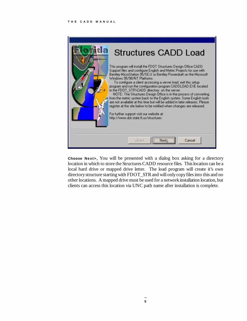
The CADD Load The SDO CADD setup is available as one executable file downloadable from our Internet site at http://www.dot.state.fl.us/structures/ or FDOT Intranet site at http://designweb/structures This setup can be used for configuring Bentley MicroStation SE/95/J or Bentley Powerdraft on the Microsoft Windows 32bit Platform. The following instructions will describe how to configure a standalone workstation, load needed resource files onto a file server, and how to configure a workstation to access shared server resources.
Standalone Workstation Install and Server Resource File Installation The installation process is started by clicking on the CADDinst.exe.
An Introduction screen will explain what this program will perform.
T H E C A D D M A N U A L
5
Choose Next>, You will be presented with a dialog box asking for a directory location in which to store the Structures CADD resource files. This location can be a local hard drive or mapped drive letter. The load program will create it’s own directory structure starting with FDOT_STR and will only copy files into this and no other locations. A mapped drive must be used for a network installation location, but clients can access this location via UNC path name after installation is complete.

T H E C A D D M A N U A L
6
When satisfied with the destination directory, press the Finish button.
The resource file copy portion of the CADD load is now complete and the MicroStation configuration portion of the CADD load will start after the next step
Configuring the MicroStation environment on the Workstation Standalone or Server Client If you are installing the resource files on a file server, press Cancel to exit the MicroStation configuration program when it starts.
This portion of the CADD load will configure MicroStation to use the Structures CADD resources. This portion of the program will automatically run following the copying of resource files to the Standalone Workstation or may be executed separately to configure a Client Workstation accessing server resources, or may also be used to reconfigure a Standalone Workstation. This file is named CADDLOAD.EXE and is located in the FDOT_STR/CADD directory and may be run from either a server or locally.

T H E C A D D M A N U A L
7
Structures Resource Directory Location: The location of FDOT_STR directory may be a local drive, a mapped network drive, or a UNC pathname.
MicroStation Version and Location: Choose the version of MicroStation you are using and enter the location of the MicroStation or Powerdraft installation directory (not the executable itself). Normal installation paths are as follows:
MicroStation SE/95: drive:\win32app\ustation MicroStation J: drive:\Bentley PowerDraft: drive:\win32app\draft PowerDraft J: drive:\Bentley

T H E C A D D M A N U A L
8
License Information: Determine if you are using a standalone license located in the local MicroStation directory structure or if you are using select server or a pooled license on a server (SE/95). If using a pooled license, enter the path to the license pool directory (not the license file itself). This path may use a mapped server drive or a UNC pathname. If using select server, enter the servername (not the UNC name.) Microstation J Help Setup If using DynaWeb Help Server, enter the server name (not the UNC name.) User Preference Location: Enter the directory location for storage of the user preference file steng.upf or stmet.upf. This may be either a local or network location. When the required input is entered, press the Configure button to complete the configuration of MicroStation to use the Structures Design Office CADD Resources. At this time four (4) files are created with the MicroStation directory structure as follows: MicroStation SE/95: ustation\config\project\steng.pcf (English project configuration file) ustation\config\project\stmet.pcf (Metric project configuration file) ustation\config\user\steng.ucf (English user configuration file) ustation\config\user\stmet.ucf (Metric user configuration file)
MicroStation J: bentley\workspace\projects\steng\steng.pcf (Eng. project configuration file) bentley\workspace\projects\stmet\stmet.pcf (Metric project configuration file) bentley\workspace\users\steng.ucf (English user configuration file) bentley\workspace\users\stmet.ucf (Metric user configuration file)
If these files already exist they will be renamed to stengpcf.old, stmetpcf.old, stengucf.old, & stmetucf.old. If the *.old files already exist. They will be deleted.
These are the only files written into the MicroStation directory structure.

T H E C A D D M A N U A L
9
Entering a Structures Workspace for the first time:
Start MicroStation. If this is the first time you have run MicroStation, you may be asked for License information. Choose the 15 minute tryout button which will take you to the MicroStation Manager window.
From the Workspace pull down, choose either steng99 to use the Structures English Workspace or stmet to use Structures Metric Workspace. Select an existing file or create a new file and press the OK to continue. Resources such as the menubar, cells, seed files, settings, applications, etc. will be available to you.

T H E C A D D M A N U A L
10
General Production The following files are automatically attached when you run the SDO CADD Load, and choose the steng Workspace in MicroStation Manager.
Cell Library: StEng.cel
Color Table: color.tbl
Proj2d.cel -this cell library is intended to be a "users" library available on each platform. Users can save "job specific" cells here. This "project" library, along with the "master,” should be archived with the design files at the close of the job. Any "proj2d" cells that may be of use to others should be brought to the attention of the CADD Development Section so that it may be included in the master cell library. Level Symbology - Use of established symbologies is required and can be selected from the SDO Menubar. Scales, Text/Dimensions and Borders All elements should be drawn at "Full Size" and completed before placing text or dimensions. After all elements are drawn, then determine the "Overall" Border scale required. Any details that may need to be scaled up or down should be done at this time. Select the Border scale from the Menubar and place the Border Cell at this scale. (You may want to use the Scale Tables provided in this manual) Select the Text Level from the Menubar, select the appropriate size, then place text and Dimensions. It is helpful to show the Scale of your Drawing and related details inside the Display area of your file but outside the Border area. This will be helpful to you and others who work on the file.

T H E C A D D M A N U A L
11
Scales The following chart is intended to aid the user in determining the appropriate scale for placing the border and text on a drawing based on the actual size of the drawing. Calculations are based on a 9.72" x 15.37" drawing area on the border.
Drawing Scale Active Scale (AS) Height (FT.) Width (FT.)
1/16" = 1' 192 155.52 245.92
3/32" = 1' 128 103.68 163.95
1/8" = 1' 96 77.76 122.96
3/16" = 1' 64 51.84 81.97 1/4" = 1' 48 38.88 61.48 3/8" = 1' 32 25.92 40.99 ½" = 1' 24 19.44 30.74
3/4" = 1' 16 12.96 20.49 1" = 1' 12 9.72 15.37
1 ½" = 1' 8 6.48 10.25
3" = 1' 4 3.24 5.12
6" = 1' 2 1.62 2.56
1' = 1' 1 .810 1.28
FORMULAS :
AS = 12 / Drawing Scale, Ex. 1/4" = .25 in., then 12 / .25 = 48, Therefore AS = 48. W = Sheet Width (in.) / Drawing Scale Ex. 1/4" = .25 in., then 32 / .25 = 128, Therefore W = 128. H = Sheet Height (in.) / Drawing Scale
Ex. 1/4" = .25 in., then 19.5 / .25 = 78, Therefore H = 78.
T H E C A D D M A N U A L
12
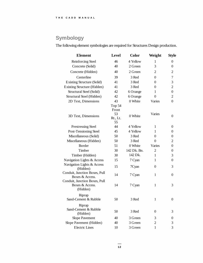
Symbology The following element symbologies are required for Structures Design production.
Element Level Color Weight Style Reinforcing Steel 46 4 Yellow 1 0 Concrete (Solid) 40 2 Green 3 0
Concrete (Hidden) 40 2 Green 2 2 Centerline 39 3 Red 0 7
Existing Structure (Solid) 41 3 Red 0 3 Existing Structure (Hidden) 41 3 Red 0 2
Structural Steel (Solid) 42 6 Orange 1 0 Structural Steel (Hidden) 42 6 Orange 0 2
2D Text, Dimensions 43 0 White Varies 0
3D Text, Dimensions
Top 54 Front
53 Rt., Lt.
55
0 White
Varies
0
Prestressing Steel 44 4 Yellow 1 0 Post-Tensioning Steel 45 4 Yellow 1 0 Miscellaneous (Solid) 50 3 Red 0 0
Miscellaneous (Hidden) 50 3 Red 0 2 Border 51 0 White Varies 0 Timber 30 142 Dk. Bn. 2 0
Timber (Hidden) 30 142 Dk. Brn
1 3 Navigation Lights & Access 15 7 Cyan 1 0 Navigation Lights & Access
(Hidden) 15 7Cyan 0 3
Conduit, Junction Boxes, Pull Boxes & Access. 14 7 Cyan 1 0
Conduit, Junction Boxes, Pull Boxes & Access.
(Hidden) 14 7 Cyan 1 3
Riprap Sand-Cement & Rubble
50
3 Red
1
0
Riprap Sand-Cement & Rubble
(Hidden)
50
3 Red
0
3
Slope Pavement 40 3 Green 3 0 Slope Pavement (Hidden) 40 3 Green 2 3
Electric Lines 10 3 Green 1 3

T H E C A D D M A N U A L
13
Element Level Color Weight Style Fence 43 6 Orange 1 0
Site Gas Lines 10 0 white 1 3 R/W Line 37 0 White 2 0
Site Sewer Lines 10 3 Green 1 3 Site Telephone Lines 10 6 Orange 1 3
Site Water Lines 10 7 Cyan 1 3
Colors: colors are dependent upon your design file color table. "Color.tbl" has the above colors. Therefore, it is important that "color.tbl" is loaded.
Text Size: Annotation = 0.0063 x (Active Scale). The SDO CADD Menubar provides all needed text sizes. The absolute minimum text size after plotting shall be .0063'. This is the smallest text size you should use on plans due to "half-sizing."
Text Sizes and Weights All standard text sizes may be selected from the Menubar. The SDO uses special, custom fonts in its drawings and programs, specifically, Fonts 68 and 69. So that text displays properly, a font library is included in the purchase of a set of Standard Drawing files.
TITLE WEIGHT SIZE (Ft) Special Small/Revisions 0 .0050
Annotation 1 .0063 View/Sheet/Sect Titles 2 .0073
Large 3 .0084 Extra Large 3 .0100
NOTE: Sizes shown are a 1:1 ratio.
Special Symbols The SDO also uses special symbols that are part of the SDO font library. For example, in Font 68, if you key in a question mark, the result will be a Roman numeral one on the screen. The symbols are listed below:
! Roman Numeral 5 1/3 Baseline ? Roman Numeral 1 1/64 plate \ diameter mark 3/64 plus/minus sign ^ Degree symbol 5/64 squared 2 | Centerline 7/64 cubed 3

T H E C A D D M A N U A L
14
Design File Naming In order to facilitate the indexing, archival and retrieval of design files, FDOT has developed a naming convention. All standard drawings shall be named using the individual index number. (Ex. index 700 = 700.dgn) Use the following format for selecting a name for a particular design file:
Structural Plans
Design File Name Sheet Description AccessOpen Access Opening
ApproachSlab Approach Slab BaileyBridge Bailey Bridge Details
BeamLay Beam Layout BeamLayBulbT Bulb-T Beam Layout BeamLayInvT Inverted T Beam Layout
BeamLayT T Beam Layout BearingDet Bearing Details BearingPads Neoprene Bearing Pads BearingPlates Beveled Bearing Plates
Borings Foundation Investigation (Borings) BridgeHydro Bridge Hydraulic Recommendation Sheet
BrigeSection Section through bridge showing the superstructure. Use this filename for the BDR or 30% plans.
Bulkhead Bulkhead BulkheadDet Bulkhead Details
Camber Camber Diagrams ClosureJoint Closure Joint Details
ContinuityTend Continuity Tendon CoverSheet Cover Sheet ConstNotes Construction Notes ConstDet Construction Details ConstSeq Construction Sequence
ConduitDet Utility Conduit Details CPTSound CPT Soundings CrashWall Crash Wall
CrossFrameDet Cross Frame Details CulvertDet Culvert Details
DiaphragmDet Diaphragm Details DrainDet Drain Details
DrillShaft10 Drilled Shaft Pier No. 10 DrillShaftDet Drilled Shaft Details
EndBent End Bent EndBent1 End Bent No.1
EndBentDet End Bent Details ErectSeq Erection Sequence

T H E C A D D M A N U A L
15
Structural Plans Design File Name Sheet Description
ErectProced Erection Procedure for Launching Girder ExpJointDet Expansion Joint Details ExistingPlans Existing Bridge Plans FinishGrEL Finish Grade Elevations FoundLay Foundation Layout Footing3 Footing No.3
FootingDet Footing Details FramingPlan Framing Plan
FenderSystem Fender System FenderDet Fender Details FieldSplice Bolted Field Splice
FieldSpliceDet Bolted Field Splice Details FloorBeam Floor Beams
FuturePTLay Future Post-Tensioning Layout GeneralNotes General Notes
Handrail Handrail Index Index of Sheets
IntBent Intermediate Bent IntBent5 Intermediate Bent No.5
IntBentDet Intermediate Bent Details JackingDet Jacking Details
JunctionBox Junction Box KeySheet Bridge Rehab Key Sheet
LadderDet Ladder Details LongPT10 Longitudinal Post-Tensioning Span 10 MiscDet Miscellaneous details
MaintLight Maintenance lighting plan MaintLightDet Maintenance lighting details
MSEwall Mechanically stabilized earth wall MSEwall25 25’ MSE Wall
PileData Pile data table used in the foundation layout PileDet Pile Details Pier2 Pier No.2
PierDet Pier Details PierPTDet Precast Box Pier Post-Tensioning Details PotBearing Pot Bearing Details Preliminary Preliminary Plan and Elevation PlanElevP Plan and Elevation PrestSlab Prestressed Slab Units PTDet Post-Tensioning Details
PTQuantities Post-Tensioning Quantities RebarList Reinforcing Bar List
ReinfSegABC Reinforcing Segements A,B and C ReinfPierSeg Reinforcing in Pier Segments ReinfAbutSeg Reinforcing in Abutment Segments RemoveExist Removal of Existing Structures

T H E C A D D M A N U A L
16
Structural Plans Design File Name Sheet Description
RetainingWall25 25’ Retaining Wall RiprapRubble Rubble Riprap RiprapSand Sand Cement Riprap SegLayout Segment Layout
SegDimAbut Abutment Segment Dimensions SegDimBox Precast Box Segment Dimensions SegDimCap Pier Cap Segment Dimensions SegDimPier Pier Segment Dimensions
SheetPileWall Sheet Pile Retaining Wall SheetPileWallST Steel Sheet Pile Retaining Wall
SheetPileWallConc Concrete Sheet Pile Retaining Wall SheetPileWall20 20’ Sheet Pile Retaining Wall
SheetPileWallAnch Anchored Sheet Pile Wall SheetPileWallCant Cantilever Sheet Pile Wall
SidewalkDet Sidewalk Details SlidingPlate Sliding Plate Assembly
Superst Superstructure Superst100 100’ Span Superstructure Superst45 45’ Span Superstructure
SuperstDet Superstructure Details SteelGirder Steel Girder
SteelDet Steel Girder Details Stiffener Stiffener Details
SurfaceFinish Surface Finish Details TendonCurveDet Tendon Curvature Details
TransPTPier Pier Transverse Post-Tensioning TransPTAbut Abutment Transverse Post-Tensioning
TransTendonDet Transverse Tendon Details TypicalSection Typical section through bride deck
VertCurveSuperEL Vertical Curve and Superelevation Transition
Mechanical and Electrical Bridge Plans Design File Name Sheet Description
BasculePier Bascule Pier BasculeSpan Bascule Span CatwalkDet Catwalk Details
ConduitRiser Conduit Riser CommLayout Communications Layout ControlDesk Control Desk
ControlTower Control Tower CounterWt Counter Weight DriveAssem Drive Assembly
GridDeckDet Grid Deck Details Grounding Grounding and Lighting Protection

T H E C A D D M A N U A L
17
HouseLayout House, Lighting and Pier Layout IOpoints Input Output Points, PLC
LadderLogic Ladder Logic, PLC Legend Symbol Legend
LockPlan Lock Plan LockDet Lock Details MechPlan Mechanical Plan MechDet Mechanical Details
NaviLightDet Navigation Lighting System Details PanelBoardSch Panel Board Schedule
PinionDet Pinion Details Plumbing Plumbing RestPier Rest Pier
SingleLine Single Line Diagram SitePlan Site Plan for Rest Area
SubCableDet Submarine Cable Details TrunAssem Trunnion Assembly TrunBrace Trunnion Bracing TrunDet Trunnion Details WorkID Work Identification Sheet
Additional Scour Protection Plan File Names
Design File Name Sheet Description BotContourMap Bottom Contour Map
ScourPlan Plan View of Scour Protection Protection ScourProf Profile of Scour Protection
ScourDetail Scour Protection Details
Additional Load Test Plan File Names Design File Name Sheet Description
CompTestSetup Compression Test Setup DrillShaftLT123 Drilled Shaft Load Test Sites 1,2 & 3
InstruDet Instrumentation Details LTSumPile Pile Load Test Program Summary
LTSumDrillShaft Drilled Shaft Load Test Program Summary LTFrame Load Test Frame Configuration
LTBraceDet Load Test Reaction Girder Bracing Details LTGirderDet Load Test Reaction Girder Details
OsterbergCell3000 Osterberg Cell 3000 ton Load Testing Device PlatformDet Service Platform Deck and Frame Details StatnamicLT Statnamic Load Test Details

T H E C A D D M A N U A L
18
LateralLT Lateral Load Test Details
Civil (Architectural Plans) Design File Name Sheet Description
C-FP Floor plan C-SP Site plan C-D Demolition plan C-EP Environmental C-GP Grading C-RP Roads/Topographic C-SV Survey C-UP Utilities C-QP Equipment plan C-XP Existing plan C-EL Elevation C-SC Section C-DT Detail C-SH Schedules C-3D Isometric/3D C-DG Diagrams
Process (Architectural Plans) Design File Name Sheet Description
D-FP Floor plan D-SP Site plan D-DP Demolition plan D-QP Equipment plan
Geotechnical (Architectural Plans) Design File Name Sheet Description
B-FP Floor plan B-SP Site plan B-DP Demolition plan B-QP Equipment plan B-XP Existing plan B-EL Elevation B-SC Section B-DT Detail B-SH Schedules B-3D Isometric/3D B-DG Diagrams

T H E C A D D M A N U A L
19
D-XP Existing plan D-EL Elevation D-SC Section D-DT Detail D-SH Schedules D-3D Isometric/3D D-DG Diagrams
Electrical (Architectural Plans) E-FP Floor plan E-SP Site plan E-CP Communication E-GP Grounding E-LP Lighting E-PP Power E-DP Demolition plan E-QP Equipment plan E-XP Existing plan E-EL Elevation E-SC Section E-DT Detail E-SH Schedules E-3D Isometric/3D E-DG Diagrams
Fire Protection (Architectural Plans)
Design File Name Sheet Description F-FP Floor plan F-SP Site plan F-DP Demolition plan F-QP Equipment plan F-XP Existing plan F-EL Elevation F-VP Evacuation plan F-KP Sprinkler plan F-SC Section F-DT Detail F-SH Schedules F-3D Isometric/3D F-DG Diagrams
Interiors (Architectural Plans)

T H E C A D D M A N U A L
20
Fire Protection (Architectural Plans) Design File Name Sheet Description
I-FP Floor plan I-SP Site plan I-DP Demolition plan I-QP Equipment plan I-XP Existing plan I-CP Ceiling plan I-EP Enlarged plan I-RP Furniture plan I-NP Finish plan I-EL Elevation I-SC Section I-DT Detail I-SH Schedules I-3D Isometric/3D I-DG Diagrams
Mechanical (Architectural Plans)
Design File Name Sheet Description M-FP Floor plan M-SP Site plan M-DP Demolition plan M-QP Equipment plan M-XP Existing plan M-CP Control plan M-HP HVAC ductwork plan M-EL Elevation M-SC Section M-DT Detail M-SH Schedules M-3D Isometric/3D M-DG Diagrams
Plumbing (Architectural Plans) Design File Name Sheet Description
P-FP Floor plan P-SP Site Plan P-DP Demolition plan P-QP Equipment plan

T H E C A D D M A N U A L
21
P-PP Plumbing Plans P-XP Existing plan P-EL Elevation P-SC Section P-DT Detail P-SH Schedules P-3D Isometric/3D P-DG Diagrams
Structural (Architectural Plans)
S-FP Framing plan S-NP Foundation plan S-SP Site Plan S-DP Demolition plan S-QP Equipment plan S-XP Existing plan S-EL Elevation S-SC Section S-DT Detail S-SH Schedules S-3D Isometric/3D S-DG Diagrams
Telecommunications (Architectural Plans) Design File Name Sheet Description
T-FP Floor plan T-SP Site Plan T-DP Demolition plan T-QP Equipment plan T-DP Data T-TP Telephone T-XP Existing plan T-EL Elevation T-SC Section T-DT Detail T-SH Schedules T-3D Isometric/3D T-DG Diagrams
Formats for Sheet File Names

T H E C A D D M A N U A L
22
General (Architectural Plans) G-001 General G-101 Plans G-201 Elevations G-301 Sections G-401 Large Scale Views G-501 Details G-601 Schedules and Diagrams G-701 User Defined G-801 User Defined G-901 3D Representation
Hazardous Material (Architectural Plans)
Design File Name Sheet Description H-001 General H-101 Plans H-201 Elevations H-301 Sections H-401 Large Scale Views H-501 Details H-601 Schedules and Diagrams
Civil (Architectural Plans) C-001 General C-101 Plans C-201 Elevations C-301 Sections C-401 Large Scale Views C-501 Details C-601 Schedules and Diagrams C-701 User Defined C-801 User Defined C-901 3D Representation
Landscape (Architectural Plans) L-001 General L-101 Plans L-201 Elevations L-301 Sections L-401 Large Scale Views

T H E C A D D M A N U A L
23
L-501 Details L-601 Schedules and Diagrams L-701 User Defined L-801 User Defined L-901 3D Representation
Structural (Architectural Plans) Design File Name Sheet Description
S-001 General S-101 Plans S-201 Elevations S-301 Sections S-401 Large Scale Views S-501 Details S-601 Schedules and Diagrams S-701 User Defined S-801 User Defined S-901 3D Representation
Architectural (Architectural Plans) A-001 General A-101 Plans A-201 Elevations A-301 Sections A-401 Large Scale Views A-501 Details A-601 Schedules and Diagrams A-701 User Defined A-801 User Defined A-901 3D Representation
Interiors (Architectural Plans) I-001 General I-101 Plans I-201 Elevations I-301 Sections I-401 Large Scale Views I-501 Details I-601 Schedules and Diagrams

T H E C A D D M A N U A L
24
Interiors (Architectural Plans) I-701 User Defined I-801 User Defined I-901 3D Representation
Equipment (Architectural Plans)
Design File Name Sheet Description Q-001 General Q-101 Plans Q-201 Elevations Q-301 Sections Q-401 Large Scale Views Q-501 Details Q-601 Schedules and Diagrams Q-701 User Defined Q-801 User Defined Q-901 3D Representation
Fire Protection (Architectural Plans) F-001 General F-101 Plans F-201 Elevations F-301 Sections F-401 Large Scale Views F-501 Details F-601 Schedules and Diagrams F-701 User Defined F-801 User Defined F-901 3D Representation
Architectural Plans P-001 General P-101 Plans P-201 Elevations P-301 Sections P-401 Large Scale Views P-501 Details P-601 Schedules and Diagrams P-701 User Defined P-801 User Defined P-901 3D Representation
Mechanical (Architectural Plans) Design File Name Sheet Description

T H E C A D D M A N U A L
25
M-001 General M-101 Plans M-201 Elevations M-301 Sections M-401 Large Scale Views M-501 Details M-601 Schedules and Diagrams M-701 User Defined M-801 User Defined M-901 3D Representation
Electrical (Architectural Plans) E-001 General E-101 Plans E-201 Elevations E-301 Sections E-401 Large Scale Views E-501 Details E-601 Schedules and Diagrams E-701 User Defined E-801 User Defined E-901 3D Representation Telecommunication (Architectural Plans) T-001 General T-101 Plans T-201 Elevations T-301 Sections T-401 Large Scale Views T-501 Details T-601 Schedules and Diagrams T-701 User Defined T-801 User Defined T-901 3D Representation
Resource (Architectural Plans) Design File Name Sheet Description
R-FP Floor plan R-SP Site plan R-DP Demolition plan R-QP Equipment plan R-XP Existing plan R-EL Elevation R-SC Section R-DT Detail

T H E C A D D M A N U A L
26
R-SH Schedules R-3D Isometric/3D R-DG Diagrams
Other Disciplines (Architectural Plans) X-001 General X-101 Plans X-201 Elevations X-301 Sections X-401 Large Scale Views X-501 Details X-601 Schedules and Diagrams X-701 User Defined X-801 User Defined X-901 3D Representation
Contractor/Shop Drawings (Architectural Plans) Z-001 General Z-101 Plans Z-201 Elevations Z-301 Sections Z-401 Large Scale Views Z-501 Details Z-601 Schedules and Diagrams Z-701 User Defined Z-801 User Defined Z-901 3D Representation

T H E C A D D M A N U A L
27
Seed Files The Structures Design Office CADD Load is delivered with the following active parameters set in the DGN seed files. STENG2D.DGN (2D File) Views on = 1, 2 Levels Displayed = 1-63 Locks on = Snap (Keypoint) Active Level (LV) = 40 Color (CO) = 2 Weight (WT) = 3 Angle (AA) = 0 Scale (AS) = 1 : 1 Line Code (LC) = 0 Grid Units (GU) = 0.008,12 Global Origin (GO) = 0,0 Font (FT) = 68 Text Size (TX) = 0.0063 Line Spacing (LS) = 0.0047 (75% of text size) Line Length (LL) = 255 Cell Library = STENG.CEL (in drive:fdot_str\cadd\cell) Color Table = COLOR.TBL (Microstation color table) STENG3D.DGN (3D File) Views on = 1 (Top), 5 (Iso), 6 (Top), 7 (Front), 8 (Right) Levels Displayed = 1-63 Locks on = Snap (Keypoint) Active Level (LV) = 40 Color (CO) = 2 Weight (WT) = 3 Angle (AA) = 0 Scale (AS) = 1 Line Code (LC) = 0 Active Point: XY = 0,0,0 Display Depth (DP) = -500,500 Window Center (WO) = 0,0,0 Grid Units (GU) =0.008,12 Global Origin (GO) = 0,0 Font (FT) = 68 Text Size (TX) = 0.0063 Line Spacing (LS) = 0.0047 (75% of text size) Line Length (LL) = 255

T H E C A D D M A N U A L
28
Cell Library = STENG3D.CEL (in drive:fdot_str\cadd\cell) Color Table = COLOR.TBL (Microstation color table) Additional Parameters: (Design Options) Working Units (MU:SU:PU) = 1:12:1600 or 223696 sq ft. Angle Format = Degrees, Minutes, Seconds (DDD^MM'SS.SS") Mode = Conventional Data Readout Format = Master Units Accuracy = 0.1234 Angle Round-Off = 0^00'00.00" Dimensioning English, AEC Substitute Symbol (Arrowhead) = ALT (Cell) Linear Accuracy = 0.0001 Degree Accuracy = 0.001

T H E C A D D M A N U A L
29
Design File Settings The Structures Design Office (SDO) CADD load is delivered with the following pre-set designfile settings.

T H E C A D D M A N U A L
30
Color 1
Coordinate Readout 1

T H E C A D D M A N U A L
31
Grid 1
Snaps 1

T H E C A D D M A N U A L
32
Working Units 1

T H E C A D D M A N U A L
33
Workspace Preferences The Structures Design Office CADD load is delivered with the following preference settings.
Line Weights 1

T H E C A D D M A N U A L
34

T H E C A D D M A N U A L
35

T H E C A D D M A N U A L
36

T H E C A D D M A N U A L
37

T H E C A D D M A N U A L
38
Dimension Settings The SDO CADD load is delivered with the following pre-set Dimension Settings.
Dimension Settings; Lines 1

T H E C A D D M A N U A L
39
Dimension Settings; Terminators 1

T H E C A D D M A N U A L
40
Dimension Settings; Text 1

T H E C A D D M A N U A L
41
Dimension Settings; Units 1

T H E C A D D M A N U A L
42

T H E C A D D M A N U A L
43
Structures Menu Bar The Structures Design Office (SDO ) CADD setup includes a custom “MDL” application, “barmenu.ma” The menubar is ‘dockable’ under the task bar,
or may be “torn away”.
Menu bar items are shown as thirteen separate pull-down menus, "Attach" through "Locks". The following pages are a description of each feature included in the menus. These pull-downs are hierarchal in nature and cannot be "torn" away.
Attach
Structures English Cell Lib- Attaches the SDO English cell library (StEng.cel). Proj2d.cel (Project Specific)- Attaches the user’s 2d project cell library. RC=? - Returns the currently attached cell library. RC=: - Brings up Attach Cell Library dialog box to browse for a cell library.
T H E C A D D M A N U A L
44
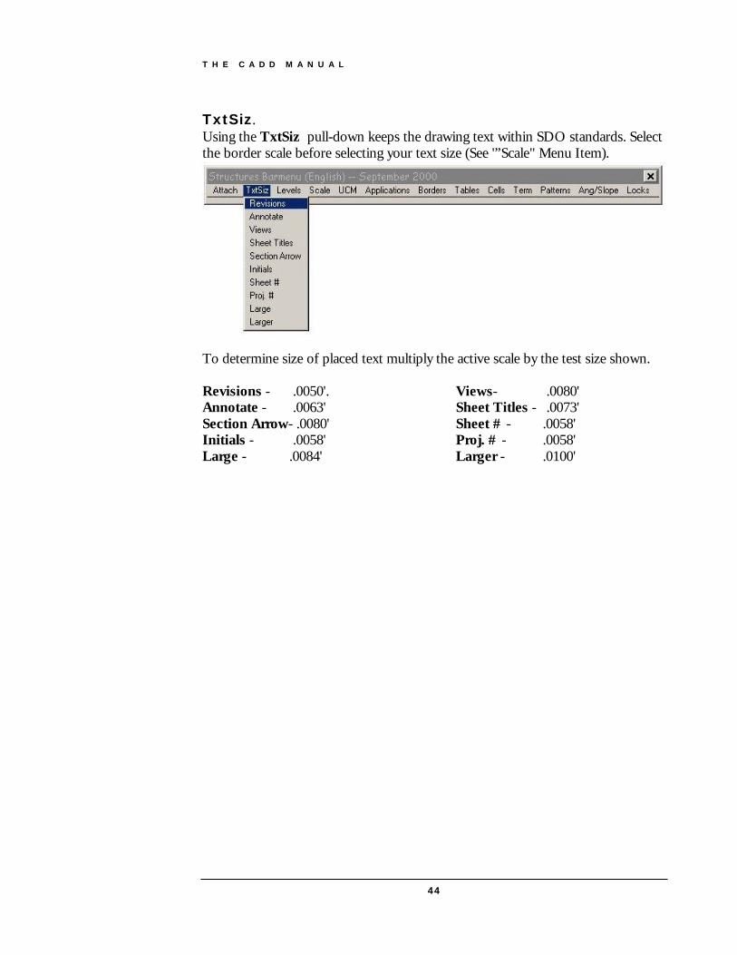
TxtSiz. Using the TxtSiz pull-down keeps the drawing text within SDO standards. Select the border scale before selecting your text size (See '”Scale" Menu Item).
To determine size of placed text multiply the active scale by the test size shown. Revisions - .0050'. Annotate - .0063'
Views- .0080' Sheet Titles - .0073'
Section Arrow- .0080' Initials - .0058'
Sheet # - .0058' Proj. # - .0058'
Large - .0084' Larger - .0100'

T H E C A D D M A N U A L
45
Levels This menu provides most of the level symbology needed to produce plans that comply with the SDO CADD Standards. These selections will set your color, level, style and weight for each type of classification. Also provided are All On and All Off for all levels and specific levels such as Plot Level 60 (shape) and Plot Level 51 (linestring). These shortcuts do away with keying in "on=" and opening the "levels" dialog box

T H E C A D D M A N U A L
46
Scale Scale selections are provided for Engineering units as well as Architectural Units. Select a scale before setting text size, choosing a line terminator, placing cells and before placing the border .
UCM (User Commands) Set Active Ang 2pts - sets the active angle to the angle between two user defined data points. Set Active Ang 3pts - sets the active angle to the angle between three user defined data points.

T H E C A D D M A N U A L
47
MDLApps The Structure’s Menubar includes applications which have been developed specifically for use in detailing structures plans. See the Table of Contents for an explanation of each application
Many other applications may be accessed as shown below.

T H E C A D D M A N U A L
48
Borders After selecting the proper scale, you may select the border you wish to place. The Structures Border is a “true half-size” border for plotting to 11 x 17 paper. The actual drawing area is 9.72" x 15.36". See “ Scales.”
Tables These tables assist in creation of commonly used items such as quantity boxes and geometry data. The horizontal and vertical curve data diagrams have data entry fields, and can be completed very quickly. Attach the Structures cell library and select the active scale before placing tables.

T H E C A D D M A N U A L
49
Cells This menu item calls the most frequently used cells in the SDO cell library that are not called by another routine. Some of these cells must have an active scale set before use. Some are meant to be placed at AS=1. Preset battered pile angles are available for pile placement. If you have any cells which may be useful to everyone as a group, please forward them to SDO CADD Development and Support Section for inclusion into the master cell library.

T H E C A D D M A N U A L
50
Term These are line terminators. The appropriate scale must be set before use. Terminators can be used individually or with auto-dimensioning. Note: if you are using a scale other than one chosen from the Scales menu, the Terminator Scale (TS=) must be set manually.
Patterns Select the proper scale and attach the “Steng” cell library before selecting a pattern command. These patterns are set up for typical use on a set of bridge plans. The pattern deltas and pattern scales present a suitable pattern at the commonly used active scales for detailed reinforcing drawings. If a particular pattern is too "thick" and/or thin, choose a different scale and re-pattern. Patterning should have a similar appearance throughout the set of plans.

T H E C A D D M A N U A L
51
Slopes These are some of the common angles or slopes that are used on FDOT drawings. A command to reset the active angle to zero is included at the top of the menu.
Locks The Locks menu item is a convenient way to access the most used locks and fence modes.

T H E C A D D M A N U A L
52
Boring Log Generator The Boring Log Generator a JMDL application that creates boring sheets using the boring data created from within the SPT97 application available on the Structures Internet Site. This application only runs from within MicroStation/J & PowerDraft/J. The application can be invoked either from the Structures Barmenu from the applications pulldown or using the keyin “java fdotsdo.jBorelog.jBorelog”.
Once invoked, enter the filename and location of the SPT97 data files that are to be used for the boring sheet generation. You may enter up to 4 input files that must all be of the same unit system (all English or all metric).
When at least one input file is chosen, the outline of the drawing will be attached to the cursor and you may place the sheet by pressing the accept button on the mouse. The program will scale text & patterning to the correct size. If you wish to override the default scales you may change the Cell & Text scales independently using the drop down lists.

T H E C A D D M A N U A L
53
Reinforcing Steel Quantity Program (Rebar)
REBAR is an MDL application for use with MicroStation. The program will calculate individual bar lengths and total up individual units (end bents, superstructures and etc). Reports can be generated and printed for use in a final computation book. All bar bends are based on the Structures Design Office Standard Index 1300. The Steng.cel must be attached to the current design file.
Program Operation:
Start Rebar by selecting the program from the Structures Menubar or key-in “MDL load rebar”. A sample input file is delivered with the program.
Pull-down Menus: File Files may be opened, saved, edited or the program may be exited. Edit Full screen edit sessions of input files. Search Search for a particular type of code. Record Go to a particular record in the input file

T H E C A D D M A N U A L
54
Price Price per pound in the Unit Code. Program will use this number to calculate the total cost of reinforcing steel for an individual bar or the
Input Codes: D-Data The reinforcing bars. V-Vary Indicates a range of bars that vary in length. *Identi. The job number, county or another identifier. U-Unit Defines the type of unit (i.e. End Bent, Wall, etc.) K–Skip This code is used to show a blank line in the input. Comment Use this code for any comment you might want to show T–Total Total weight of rebar will be computed to beginning of job or to
a preceding Total Column. Z–Z Indicates End of Data
RECORDS COMMANDS: Search Search for a particular record or type of record. First Move to first record in input file. Next Move to next record in input file. Back Move to previous record in input file. Insert Allows the user to Insert a new record Delete Deletes the current record. RUN: Report Executes the REBAR program and creates a report (RPT) file for
Reinforcing details. A report (RPT) file must be created before the Chart command can be used. (see Chart command below)
Charts Creates the Charts from the current report (RPT) file. (See Report command above)
Save Save any changes you may have made to the input file. Exit Exits the REBAR program.

T H E C A D D M A N U A L
55
Georgia Skew The Georgia Skew Program is a two step process. Data is entered into the Georgia Skew program and a report is generated. The Georgia Skew MDL application is run using this report to produce a drawing. Georgia Skew Program Operation: A program (GSKBLD.EXE) is included to help build input files for the Georgia Skew program. This program does not have to be used, input files can be built using a standard text editor to input column specific data, the file builder program just makes it easier to enter column specific data. The Georgia Skew program manual is still needed to understand how to code bridge input and in what order the input is expected. Using the Georgia Skew File Builder Program: Run the file GSKBLD.EXE to start the file builder program, you will be presented with a standard windows program interface that lets you open and/or save program data
Along the top of the edit box you will see the corresponding card column each piece of data is placed in. Each line in the box corresponds to one input card image. To

T H E C A D D M A N U A L
56
create a new card, choose the type of card to create from the list on the bottom left of the program screen and then press the Add Card button. A dialog box will appear asking for the pertinent card data. When finished entering data, press the OK button to keep the data or Cancel to discard the data. If OK is pressed, the card will be added to the end of the card list. To insert a card into the card list. First, in the card list box, highlight the card which you would like the new card to be inserted above. Next, from the list on the bottom left of the program screen, choose the type of card you would like to insert and press the Insert Card button. A dialog box will appear asking for the pertinent card data. When finished entering data press the OK button to keep the data or Cancel to discard the data. To edit an existing card just double click on the card in the card list and a dialog box will appear with the current data loaded. Change the data you need and then press OK to commit your changes or Cancel to disregard changes. To delete a card just highlight the card in the card list you would like to delete and press the Delete Card button. You will need to acknowledge that you want the card deleted. When input is completed, save your file. Then, from the Georgia Skew menu, choose Make Report to create an output report. This report is the file the Georgia Skew MDL uses to create MicroStation drawings. When the report is created, choose View Report from the Georgia Skew menu to check for any input errors. If there are no errors, you are ready to create your MicroStation drawing. Note: the report file will be created in same directory and with the same file name as the Input file except with a .rpt extension. Note: At this time Coordinate input is not handled by the file builder, therefore, it must be entered using a text

T H E C A D D M A N U A L
57
Using the Georgia Skew MDL: Open or create the .dgn file you want to create your Georgia Skew drawing in. Make sure you are using a file with the correct working units, if your Georgia Skew report contains metric output you should be using metric working units or visa-versa for English. From the Structures Menubar choose MDL APPS.->GA. Skew or use the MicroStation key-in “MDL load bdeck”.
The Georgia Skew MDL dialog box appears asking for certain information.
It is suggested that this program be run from an existing report. This will minimize undetected errors in the report file. The Input from existing report option must be enabled if using units for input or output. Enable the other Drawing options that you need. The Text Scale does not need to be set if you are using an existing report. Press RUN to start your drawing. If you are using an existing report, you will be presented with a standard file location dialog asking for the location of your report file. After choosing the report location, MicroStation will start your drawing and notify you when the drawing is complete.

T H E C A D D M A N U A L
58
Superstructure Cross Section Program (SuperSect)
Supersect is an MDL application used with MicroStation that will generate a cross section of the superstructure.
The Suprsect.cel is automatically attached to the current design file when the application is started. You must manually reattach the previous cell library.
Program Operation: After starting MicroStation, start Suprsect by selecting the program from the Structures Menu bar or key-in “MDL load suprsect”. Once you have started the program, you can create a new file by filling in the data entry boxes and using the File->Save menu item, or open an existing file by using the File->Open menu item . A sample input file is delivered with the program.

T H E C A D D M A N U A L
59
Slab Road Width Roadway width Gutter to Gutter Thickness Slab Thickness Slope Left Cross slope left of centerline Slope Right Cross slope right of centerline PGL -Lt/Rt Distance from Rt. Gutter to PGL Text Scale Scale of section. Click for options Section Draw Full or Half at a time. Click for options. Dimension Dimension Full, Top, or Bottom. Click for Options.
Options Drains Automatically draws deck drains. Ggroup Makes entire section a graphic group m/mm Shows meters or millimeters OPEN: Allows a user to open an existing input file. SAVE: Allows the user to save the existing input. DRAW: Attaches section to cursor for user placement within the design
file. EXIT: Exits the program
More>> Beams: Pressing the More>> button with Beams chosen in the Include box displays the following Beam input categories appear: BEAMS Beam Type: Choose Beam Type, click to see choices Offset First: Distance from Left Gutter to first beam. Number: Number of Beams Variable Spacing: Used for variable beam spacing. Beam Spacing: Up to 13 beams. Use spacing #1 if spacing is constant. DRAW DIAPHRAGM Concrete: Draw concrete diaphragm Steel: Draw reinforcing Steel in Diaphragm. Skew Angle: Angle at bent (Used to calculate diaphragm reinforcing spacing) Bottom Cover: Cover on stirrups in diaphragm. STEEL Pressing the More>> button with the Steel check box chosen in the Include box displays the following Steel input categories appear: STEEL SPACING

T H E C A D D M A N U A L
60
Main: Spacing for Main Steel (in). Transverse Steel (Top & Bottom) Distribution: Spacing for Distribution Steel (in). (Bottom of Slab) Continuity: Spacing for Continuity Steel over piers. (Future Option) Temperature: Spacing for Temperature Steel (in). (Top of Slab) STEEL SIZE Main: Size of Main Steel. (used for annotation) Distribution: Size of Steel Distribution. (used for annotation) Continuity: Size of Continuity Steel. (used for annotation) Temperature: Size of Temperature Steel. (used for annotation). DRAW J-Bars: Additional Bars at gutter. Formally known as J-bars. Now shown
straight. STEEL COVER Top: Cover on Top reinforcing steel. Bottom: Cover on Bottom reinforcing steel. LABELS Pressing the More>> button with the Labels check box chosen in the Include>> box displays the Labels data entry fields. Labels may be edited for use with the program.

T H E C A D D M A N U A L
61
Weld WELD is an MDL application for use with MicroStation. The program will draw weld symbols using metric or English annotation. The program reads the working units of the current design file before displaying the dialogue box. The Steng.cel or Stmet.cel must be attached to the current design file. Program Operation: After starting MicroStation, start WELD by selecting the program from the Structures Menu bar or you can key-in “mdl load weld”. Once you have started the program, select the weld size, type and a specification. Scale and text size must be selected before beginning to draw the symbol. To draw a symbol you simply “Click” on the BEGIN bar and place data points in the design file to create the leader symbol. This example shows a ¼” full penetration weld on the arrow side.
This example shows a 1/8" fillet weld on the arrow side and a 1/4" fillet weld on the otherwise. Clicking on the top or bottom boxes will reveal the range of weld sizes. This example also shows the weld on both sides with a specification. Specifications may be one to three lines in length. Various sizes of welds may be shown on the top or the bottom of the leader. There are three different types of welds; fillet, bevel and
full. One side or both sides of the leader may be selected.

T H E C A D D M A N U A L
62
The above example shows a 1/4" fillet weld on the top and bottom of the leader with an all around symbol. It also shows the fillet symbol on both sides and a one line specification. This example shows 1/4 Bevel weld on the far side with an all around symbol and a specification.
The weld symbol builder is very flexible, and almost any type of weld symbol can be created. Once a symbol is placed, the entire symbol and the annotation can be manipulated at once with the graphic group lock turned-on.

T H E C A D D M A N U A L
63
Elevation Flag Modifier (Elmod) This mdl application is used with the “gaskew” application. Gaskew (Georgia Skew Geometry program) builds a design file after calculating all of the bridge deck elevations. The design file has all the elevations positioned on a flag in a plan view of the deck. Elevmod provides a quick and easy way to clean up any or all annotations the program could not fit well. The Text Scale and Line Spacing (spacing of text above the flag leader) is required as input. A line string “flag” of the proper size is required to be hand-built before using the application if you wish to change the size of the annotation flag. This application can be used to change one flag at a time or used with a fence to change multiple flags at one time.

T H E C A D D M A N U A L
64
INDEX Applications, 9
Boring Log Generator, 52 Elevmod, 63 Georgia Skew, 55, 63 Rebar, 53, 54 Suprsect, 58 Weld, 61
Border, 10, 12 Boring Log Generator, 52 CADD Load, 10 Cell Library, 43 Cells, 9, 10, 46, 49 Color Table, 13 Design File Naming
Architectural Plans Civil, 18 Architectural Plans Electrical, 19 Architectural Plans Fire Protection, 19 Architectural Plans Geotechnical, 18 Architectural Plans Interiors, 19 Architectural Plans Mechanical, 20 Architectural Plans Plumbing, 20 Architectural Plans Process, 18 Architectural Plans Structural, 21 Architectural Plans Telecommunications, 21 Structural Load Test, 17 Structural Mechanical & Electrical, 16 Structural Plans, 14 Structural Scour Protection, 17
Design File Settings Color, 30 Coordinate Readout, 30
Snaps, 31 Working Units, 32
Dimension Settings Terminators, 39 Text, 40 Units, 41
Elevation Flag Modifier, 63 Georgia Skew, 55 Menubar
Applications, 47 Borders, 48 Cells, 49 Levels, 45 Locks, 51 Patterns, 50 Scale, 44, 46, 50 Slopes, 51 Tables, 48 Terminators, 50 Text Size, 44
Reinforcing Steel Quantity Program, 53 Scale, 10, 11, 22, 46
Border, 10 Drawing, 11
Seed files, 27 Special Font Symbols, 13 Superstructure Cross Section Program, 58 Symbology, 10, 12 Text Size, 13, 46 Weld, 61 Workspace Preferences, 33

Fractions of Inch and Decimals of a Foot