Flooded Screw Chiller Technical Sales Guide - Gree · LS 180 Model H Nb Water Chiller Nominal...
19
-
Upload
nguyenkhue -
Category
Documents
-
view
220 -
download
3
Transcript of Flooded Screw Chiller Technical Sales Guide - Gree · LS 180 Model H Nb Water Chiller Nominal...


1. MODELS LIST
2. NOMENCLATURE
3. FEATURES
4. PRODUCT DATA
5. PERFORMANCE CORRECTION
6. ANTIFREEZE
7. INSTALLATION
8. ELECTRICAL DATA
9. SCHEMATIC WIRING DIAGRAM
10.MICROPROCESSOR CONTROLLER
11.APPLICATION DATA
1
3
6
13
3
9
13
17
17
18
18
11 MODELS LIST
Nominal Capacity Model
Refrigerant
R134a
RT
52
60
68
84
97
109
126
144
165
181
193
218
250
286
328
362
Model Name
LSBLG180H/Nb-M
LSBLG210H/Nb-M
LSBLG240H/Nb-M
LSBLG300H/Nb-M
LSBLG340H/Nb-M
LSBLG380H/Nb-M
LSBLG450H/Nb-M
LSBLG500H/Nb-M
LSBLG580H/Nb-M
LSBLG640H/Nb-M
LSBLG680H/Nb-M
LSBLG760H/Nb-M
LSBLG880H/Nb-M
LSBLG1000H/Nb-M
LSBLG1160H/Nb-M
LSBLG1280H/Nb-M
Power Supply
Ph, V, Hz
3,380~415,50
3,380~415,50
3,380~415,50
3,380~415,50
3,380~415,50
3,380~415,50
3,380~415,50
3,380~415,50
3,380~415,50
3,380~415,50
3,380~415,50
3,380~415,50
3,380~415,50
3,380~415,50
3,380~415,50
3,380~415,50

180=182kW= 52 RT
210=212kW= 60 RT
240=238kW= 68 RT
300=296kW= 84 RT
340=340kW= 97 RT
380=383kW= 109 RT
450=445kW= 126 RT
500=508kW= 144 RT
580=582kW= 165 RT
640=637kW= 181 RT
680=680kW= 193 RT
760=767kW= 218 RT
880=880kW= 250 RT
1000=1006kW= 286 RT
1160=1155kW= 328 RT
1280=1275kW= 362 RT
Options
LS
180
Model
H
Nb
Water Chiller
Nominal Cooling Capacity
Model Description
Flooded
Refrigeration Nb - R134a
BLG Screw Compressor
22 NOMENCLATURE
LS B LG 180 H / Nb-M
33 FEATURES
3.1 Description
With a wide cooling capacity range from 180 to 1280 kW, GREE water-cooled screw chillers are being
selected by more and more user for high efficiency and absolute dependability, GREE chillers are new
widely applied in hotel, apartment, restaurant, office building, shopping mall, theater, gymnasium,
hospital and so on, as well as supplying cool water for machine cooling purpose based on customized
design all over the world.
3.2 Standard Specifications
High Efficiency Full Load Operation
Utilizing new screw compressor technology, the chillers meet or exceed the performance requirements
of ASHRAE 90.1. All system components are selected for optimum performance, including the
condenser and evaporatars sizes.
Excellent part load performance
Because the units are not operated in full load condition most of the time, integrated part load value
Flooded Screw Chiller Technical Sales Guide
M Power Supply 380~415V,3ph,50Hz

4
Compressor
Condenser
(IPLV) is an important performance indicator as outlined in standard ARI550/590-1998. Thanks to the
patented design of two system parallel connection technology, a excellent IPLV performance has been
come true.
Capacity control
Step or stepless capacity control are optional available, enable the unit be turned on with the least load
to reduce startup current; and match up capability output of the units to actual load, which make the
units operate steadily and reduce operation cost.
Compact suction gas cooled semi-hermetic twin screw compressors with high efficiency performance
curve. Compressors are provided with high efficiency suction strainer, oil trainer crank case heater and
built in safety pressure relief valve. Compressors are also provided with intelligent electronics including
motor temperature monitoring, phase reversal protection, manual reset lock-out and discharge
temperature protection by PTC`s sensors. Optimized oil management ensure minimum refrigerant
dilution in oil.
Cooler
Flooded type, shell-and-tube type with refrigerant evaporated inside the shell and water flowing in the
tubes. With special high efficiency pool boiling heat-exchange tubes, which are expanded into a steel
plate, the flooded type structure enable both the theories of pool boiling and nucleation boiling be well
applied.
Thus, the uniform refrigerant distribution, optimized temperature field of heat transferring, heightened
evaporating temperature are achieved, and cooling capacity and EER of the unit are improved greatly.
All evaporator are designed, constructed, inspected, and stamped according to the requirements of the
ASME Boiler and Pressure Vessel Code.
The condenser is shell-and-tube type, carbon steel fin and seamless high efficiency copper tubes with
inside the shell and flowing through the tubes. Each condenser is
designed, constructed, inspected, and stamped according to the requirements of the ASME Boiler and
Pressure Vessel Code.
Refrigerant condensing water
Reliable oil return
In order to ensure the oil in refrigeration system returning to compressor, the secondary oil separator
with both centrifugal and absorption setups is used for improving the separating efficiency of oil from
refrigerant, and a kind of injection equipment of refrigerant is specially designed which can be a great
help of oil returning into compressor from refrigeration circuit;
At the same time, the low oil location protection is applied to avoid the damnification to compressor
from low oil to ensure reliability of the chiller.
Strict Out-going test
Each unit will be tested strictly not only on nominal operation condition but also minimum/maximum
operation condition when leave factory by advanced on-line test system.
Superior Controls
3.3 Standard Accessories
Water flow switch
Unit on-off switch
Filter drier
Under voltage and phase protection
Sight glass
Liquid line solenoid valve
5
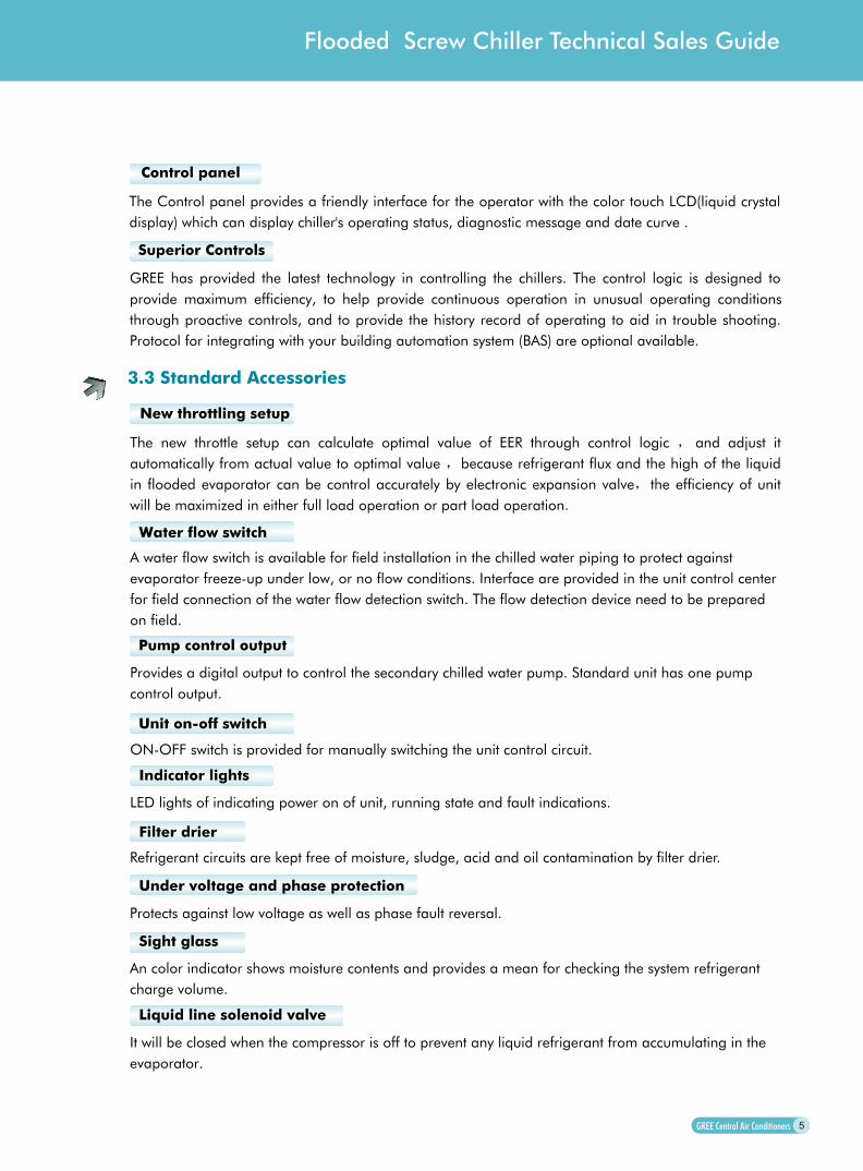
Control panel
The Control panel provides a friendly interface for the operator with the color touch LCD(liquid crystal
display) which can display chiller's operating status, diagnostic message and date curve .
GREE has provided the latest technology in controlling the chillers. The control logic is designed to
provide maximum efficiency, to help provide continuous operation in unusual operating conditions
through proactive controls, and to provide the history record of operating to aid in trouble shooting.
Protocol for integrating with your building automation system (BAS) are optional available.
New throttling setup
The new throttle setup can calculate optimal value of EER through control logic and adjust it
automatically from actual value to optimal value because refrigerant flux and the high of the liquid
in flooded evaporator can be control accurately by electronic expansion valve the efficiency of unit
will be maximized in either full load operation or part load operation.
Indicator lights
A water flow switch is available for field installation in the chilled water piping to protect against
evaporator freeze-up under low, or no flow conditions. Interface are provided in the unit control center
for field connection of the water flow detection switch. The flow detection device need to be prepared
on field.
Pump control output
Provides a digital output to control the secondary chilled water pump. Standard unit has one pump
control output.
ON-OFF switch is provided for manually switching the unit control circuit.
LED lights of indicating power on of unit, running state and fault indications.
Refrigerant circuits are kept free of moisture, sludge, acid and oil contamination by filter drier.
Protects against low voltage as well as phase fault reversal.
An color indicator shows moisture contents and provides a mean for checking the system refrigerant
charge volume.
It will be closed when the compressor is off to prevent any liquid refrigerant from accumulating in the
evaporator.
Flooded Screw Chiller Technical Sales Guide

6
44 PRODUCT DATA
4.1 Ratings
EER=Energy Efficiency Ratio at full load-the cooling capacity in Btu's per hour(Btu/h) divided by the power input
in watts, expressed in Btu/h per watts((Btu/h)/watt).
3.4 Standard Control & Safety Devices
Safety valve
Protecting the unit against high discharge pressure.
Crankcase heaters
Compressor built-in protection device
Motor winding temperature, discharge gas temperature and phase reversal for direction of rotation.
Protects the unit against from refrigerant migration, oil dilution and potential compressor failure.
Model Capacity(kW / RT) EER
LSBLG180H/Nb-M
LSBLG210H/Nb-M
LSBLG240H/Nb-M
LSBLG300H/Nb-M
LSBLG340H/Nb-M
LSBLG380H/Nb-M
LSBLG450H/Nb-M
LSBLG500H/Nb-M
LSBLG580H/Nb-M
LSBLG640H/Nb-M
LSBLG680H/Nb-M
LSBLG760H/Nb-M
LSBLG880H/Nb-M
LSBLG1000H/Nb-M
LSBLG1160H/Nb-M
LSBLG1280H/Nb-M
182/52
212/60
238/68
296/84
340/97
383/109
445/126
508/144
582/165
637/181
680/193
767/218
880/250
1006/286
1155/328
1275/362
17.23
17.21
17.26
17.70
17.83
17.64
18.06
18.23
17.72
17.80
17.83
17.67
17.86
18.05
17.58
17.81

7
4.2 Physical Data
ModelsLSBLG H/Nb-M
Nominal Cooling Capacity
Power Consumption
kW
RT
kW
180 210 240 300 340 380 450 500
182 212 238 296 340 383 445 508
52 60 68 84 97 109 126 144
36 42 47 57 65 74 84 95
Running Control
Power Supply
The multicolor touch LCD(liquid crystal Display)
380~415V 3N 50Hz
Safeties
High/low pressure protection, discharge temp. protection, anti-freeze water flow protection , low water flow protection ,phase-sequence protection, compressor overload protection, low oil location protection, Safety valve , Crankcase heaters
Compressor Type Semi-Hermitic Screw Compressor
Refrigerant Type R134a
Water Flow9 10 11 14 16 18 21 24
GPM 136 158 180 224 260 290 334 383
Loss of Pressure 40 45 50 60 60 62 64 66
Heat Exchanger Flooded Shell and Tube Evaporator
1.4Max.Pressure
Water In/Out Pipe Diameter
DN80 DN80 DN80 DN125 DN125 DN125 DN150 DN150
Water FlowGPM 163 194 216 268 308 348 396 453
Loss of Pressure 53 54 62 62 63 62 67 68
Shell and Tube Condenser Heat Exchanger
Max. Pressure 2.0
Water In/Out Pipe Diameter
DN125 DN125 DN125 DN125 DN125 DN125 DN150 DN150
Cooler
Condenser
Dimension
Operation Weights
Shipping Weights 1800 1900 1900 2800 2900 3100 3850
1890 1995 1995 2940 3045 3255
4600
4043 4830
1487 1487 1487 1680 1680 1720 2130 2130
3160 3160 3160 3160 3160 3160 3160 3160
1150 1150 1150 1400 1400 1400 1520 1520
Height
Width
Depth
NOTES: 1 1 mm=0.0394 in. 2 Nominal Operate Condition. Inlet/Outlet chilled water temperature: 12/7 (44.6/53.6 ). Inlet/Outlet cooling water temperature: 30/35 (86.4/95.4 ).
Flooded Screw Chiller Technical Sales Guide
L/s
10 12 14 17 19 22 25 29L/s

ModelsLSBLG H/Nb-M
Nominal Cooling Capacity
Power Consumption
kW
RT
kW
NOTES: 1 1 mm=0.0394 in. 2 Nominal Operate Condition. Inlet/Outlet chilled water temperature: 12/7 (44.6/53.6 ). Inlet/Outlet cooling water temperature: 30/35 (86.4/95.4 ).
Running Control
Power Supply
Safeties
High/low pressure protection, discharge temp. protection, anti-freeze water flow protection , low water flow protection ,phase-sequence protection, compressor overload protection, low oil location protection, Safety valve , Crankcase heaters
Compressor Type Semi-Hermitic Screw Compressor
Refrigerant Type R134a
Water FlowGPM
Loss of Pressure
Heat Exchanger
1.4Max.Pressure
Water In/Out Pipe Diameter
Water FlowGPM
Loss of Pressure
Shell and Tube Condenser Heat Exchanger
Max. Pressure 2.0
Water In/Out Pipe Diameter
Cooler
Condenser
Dimension
Operation Weights
Shipping Weights
Height
Width
Depth
8
580 640 680 760 880 1000 1160 1280
582 637 680 767 880 1006 1155 1275
165 181 193 218 250 286 328 362
112 122 130 148 168 190 224 244
440 484 515 581 669 761 880 968
68 74 76 76 76 77 78 78
DN150 DN150 DN200 DN200 DN200 DN200 DN200 DN200
524 576 616 695 792 906 1052 1153
68 68 68 68 78 78 80 80
DN150 DN150 DN200 DN200 DN200 DN200 DN200 DN200
2130 2130 2030 2030 2230 2230 2230 2230
3160 3160 3400 3400 3900 3900 3900 3900
1520 1520 1700 1700 1900 1900 1900 1900
3850 4600 5100 5100 6200 6500 6500 7000
4043 4830 5355 5355 6510 6825 6825 7350
380~415V 3N 50Hz
The multicolor touch LCD(liquid crystal Display)
Flooded Shell and Tube Evaporator
L/s 28 31 33 37 42 48 56 61
L/s 33 36 39 44 50 57 66 73
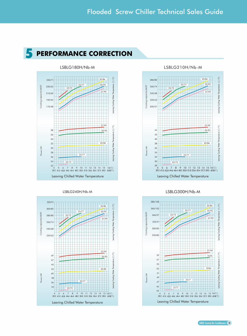
55 PERFORMANCE CORRECTION
LSBLG180H/Nb-M
Leaving Chilled Water Temperature
250/71
230/65
210/60
190/54
170/48
38
36
34
32
30
28
26
24
224 5 6 7 8 9 10 11 12 13 14 15
25/77
22/72
30/86
35/95
37/99
37/99
35/95
30/86
25/77
22/72
LSBLG210H/Nb-M
Leaving Chilled Water Temperature
280/80
260/74
240/68
220/63
200/57
44
42
40
38
36
34
32
30
28
Leaving Chilled Water Temperature
LSBLG240H/Nb-M LSBLG300H/Nb-M
Leaving Chilled Water Temperature
380/108
360/102
340/97
320/91
300/85
230/80
59
57
55
53
51
49
47
45
43
9
Flooded Screw Chiller Technical Sales Guide
16( )
39.2 41.0 42.8 44.6 46.4 48.2 50.0 51.8 53.6 55.4 57.2 59.0 60.8( ) 39.2 41.0 42.8 44.6 46.4 48.2 50.0 51.8 53.6 55.4 57.2 59.0 60.8( )4 5 6 7 8 9 10 11 12 13 14 15 16( )
25/77
22/72
30/86
35/95
37/99
37/99
35/95
30/86
25/77
22/72
320/91
300/85
280/80
260/74
240/68
220/63
49
45
43
40
38
36
47
34
4 5 6 7 8 9 10 11 12 13 14 15 16( )
39.2 41.0 42.8 44.6 46.4 48.2 50.0 51.8 53.6 55.4 57.2 59.0 60.8( )
25/77
22/72
30/86
35/95
37/99
37/99
35/95
30/86
25/77
22/72
25/77
22/72
30/86
35/95
37/99
37/99
35/95
30/86
25/77
22/72
39.2 41.0 42.8 44.6 46.4 48.2 50.0 51.8 53.6 55.4 57.2 59.0 60.8( )
4 5 6 7 8 9 10 11 12 13 14 15 16( )
Leavi
ng C
oolin
g W
ate
r Te
mper
atu
re(
/
)Le
avi
ng C
oolin
g W
ate
r Te
mper
atu
re(
/ )
Leavi
ng C
oolin
g W
ate
r Te
mper
atu
re(
/
)Le
avi
ng C
oolin
g W
ate
r Te
mper
atu
re(
/ )
Leavi
ng C
oolin
g W
ate
r Te
mper
atu
re(
/
)Le
avi
ng C
oolin
g W
ate
r Te
mper
atu
re(
/ )
Leavi
ng C
oolin
g W
ate
r Te
mper
atu
re(
/
)Le
avi
ng C
oolin
g W
ate
r Te
mper
atu
re(
/ )

LSBLG340H/Nb-M
Leaving Chilled Water Temperature
410/116
390/111
370/105
350/99
330/94
67
65
63
61
59
57
55
53
514 5 6 7 8 9 10 11 12 13 14 15
LSBLG380H/Nb-M
Leaving Chilled Water Temperature
450/128
440/125
420/119
400/114
380/108
76
74
72
70
68
66
64
62
604 5 6 7 8 9 10 11 12 13 14 15
360/102
LSBLG500H/Nb-M
Leaving Chilled Water Temperature
580/165
560/159
540/153
520/148
500/142
97
95
93
91
89
87
85
83
814 5 6 7 8 9 10 11 12 13 14 15
480/136
LSBLG450H/Nb-M
Leaving Chilled Water Temperature
520/148
500/142
480/136
460/131
440/125
86
84
82
80
78
76
74
72
704 5 6 7 8 9 10 11 12 13 14 15
420/119
10
25/77
22/72
30/86
35/95
37/99
37/99
35/95
30/86
25/77
22/72
16( )
39.2 41.0 42.8 44.6 46.4 48.2 50.0 51.8 53.6 55.4 57.2 59.0 60.8( )
25/77
22/72
30/86
35/95
37/99
37/99
35/95
30/86
25/77
22/72
16( )
39.2 41.0 42.8 44.6 46.4 48.2 50.0 51.8 53.6 55.4 57.2 59.0 60.8( )
25/77
22/72
30/86
35/95
37/99
37/99
35/95
30/86
25/77
22/72
16( )
39.2 41.0 42.8 44.6 46.4 48.2 50.0 51.8 53.6 55.4 57.2 59.0 60.8( )
25/77
22/72
30/86
35/95
37/99
37/99
35/95
30/86
25/77
22/72
16( )
39.2 41.0 42.8 44.6 46.4 48.2 50.0 51.8 53.6 55.4 57.2 59.0 60.8( )
Leavi
ng C
oolin
g W
ate
r Te
mper
atu
re(
/
)Le
avi
ng C
oolin
g W
ate
r Te
mper
atu
re(
/ )
Leavi
ng C
oolin
g W
ate
r Te
mper
atu
re(
/
)Le
avi
ng C
oolin
g W
ate
r Te
mper
atu
re(
/ )
Leavi
ng C
oolin
g W
ate
r Te
mper
atu
re(
/
)Le
avi
ng C
oolin
g W
ate
r Te
mper
atu
re(
/ )
Leavi
ng C
oolin
g W
ate
r Te
mper
atu
re(
/
)Le
avi
ng C
oolin
g W
ate
r Te
mper
atu
re(
/ )
Leaving Chilled Water Temperature
Leaving Chilled Water Temperature
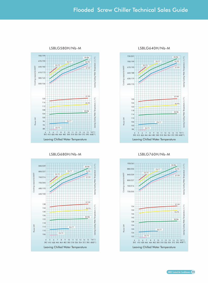
LSBLG580H/Nb-M
Leaving Chilled Water Temperature
700/199
670/190
640/182
610/173
580/165
120
116
112
108
104
100
96
92
88
4 5 6 7 8 9 10 11 12 13 14 15
550/156
LSBLG640H/Nb-M
730/207
700/199
670/190
660/188
630/179
130
126
122
118
114
110
106
102
98
4 5 6 7 8 9 10 11 12 13 14 15
600/170
LSBLG760H/Nb-MLSBLG680H/Nb-M
11
920/261
880/250
840/239
800/227
760/216
154
150
146
142
138
134
130
126
122
4 5 6 7 8 9 10 11 12 13 14 15
720/205
840/239
800/227
760/216
720/205
680/193
138
134
130
126
122
118
114
110
106
4 5 6 7 8 9 10 11 12 13 14 15
640/182
Leaving Chilled Water Temperature
Flooded Screw Chiller Technical Sales Guide
25/77
22/72
30/86
35/95
37/99
37/99
35/95
30/86
25/77
22/72
16( )
39.2 41.0 42.8 44.6 46.4 48.2 50.0 51.8 53.6 55.4 57.2 59.0 60.8( )
25/77
22/72
30/86
35/95
37/99
37/99
35/95
30/86
25/77
22/72
16( )
39.2 41.0 42.8 44.6 46.4 48.2 50.0 51.8 53.6 55.4 57.2 59.0 60.8( )
25/77
22/72
30/86
35/95
37/99
37/99
35/95
30/86
25/77
22/72
16( )
39.2 41.0 42.8 44.6 46.4 48.2 50.0 51.8 53.6 55.4 57.2 59.0 60.8( )
25/77
22/72
30/86
35/95
37/99
37/99
35/95
30/86
25/77
22/72
16( )
39.2 41.0 42.8 44.6 46.4 48.2 50.0 51.8 53.6 55.4 57.2 59.0 60.8( )
Leavi
ng C
oolin
g W
ate
r Te
mper
atu
re(
/
)Le
avi
ng C
oolin
g W
ate
r Te
mper
atu
re(
/ )
Leavi
ng C
oolin
g W
ate
r Te
mper
atu
re(
/
)
Leavi
ng C
oolin
g W
ate
r Te
mper
atu
re(
/ )
Leavi
ng C
oolin
g W
ate
r Te
mper
atu
re(
/
)Le
avi
ng C
oolin
g W
ate
r Te
mper
atu
re(
/ )
Leavi
ng C
oolin
g W
ate
r Te
mper
atu
re(
/
)Le
avi
ng C
oolin
g W
ate
r Te
mper
atu
re(
/ )
Leaving Chilled Water Temperature
Leaving Chilled Water TemperatureLeaving Chilled Water Temperature
Leaving Chilled Water Temperature
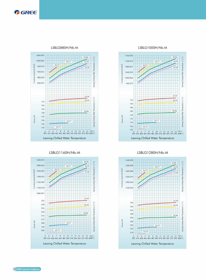
LSBLG1160H/Nb-M
1320/375
1280/364
1240/352
1200/341
1160/330
232
228
224
220
216
212
208
104
200
4 5 6 7 8 9 10 11 12 13 14 15
1120/318
1080/307
LSBLG1280H/Nb-M
1440/409
1400/398
1360/386
1320/375
1280/364
250
246
242
238
234
230
226
222
218
4 5 6 7 8 9 10 11 12 13 14 15
1240/352
LSBLG880H/Nb-M LSBLG1000H/Nb-M
1160/330
1120/318
1080/307
1040/295
1000/284
960/273
194
190
186
182
178
174
170
166
1624 5 6 7 8 9 10 11 12 13 14 15
12
4 5 6 7 8 9 10 11 12 13 14 15
1040/295
1000/284
960/273
920/261
880/250
840/237
170
166
162
158
154
150
146
142
25/77
22/72
30/86
35/95
37/99
37/99
35/95
30/86
25/77
22/72
16( )
39.2 41.0 42.8 44.6 46.4 48.2 50.0 51.8 53.6 55.4 57.2 59.0 60.8( )
Leavi
ng C
oolin
g W
ate
r Te
mper
atu
re(
/
)Le
avi
ng C
oolin
g W
ate
r Te
mper
atu
re(
/ )
25/77
22/72
30/86
35/95
37/99
37/99
35/95
30/86
25/77
22/72
16( )
39.2 41.0 42.8 44.6 46.4 48.2 50.0 51.8 53.6 55.4 57.2 59.0 60.8( )
25/77
22/72
30/86
35/95
37/99
37/99
35/95
30/86
25/77
22/72
16( )
39.2 41.0 42.8 44.6 46.4 48.2 50.0 51.8 53.6 55.4 57.2 59.0 60.8( )
25/77
22/72
30/86
35/95
37/99
37/99
35/95
30/86
25/77
22/72
16( )
39.2 41.0 42.8 44.6 46.4 48.2 50.0 51.8 53.6 55.4 57.2 59.0 60.8 ( )
Leavi
ng C
oolin
g W
ate
r Te
mper
atu
re(
/
)Le
avi
ng C
oolin
g W
ate
r Te
mper
atu
re(
/ )
Leavi
ng C
oolin
g W
ate
r Te
mper
atu
re(
/
)Le
avi
ng C
oolin
g W
ate
r Te
mper
atu
re(
/ )
Leavi
ng C
oolin
g W
ate
r Te
mper
atu
re(
/
)Le
avi
ng C
oolin
g W
ate
r Te
mper
atu
re(
/ )

66 ANTIFREEZE
A glycol solution is required when ambient temperature is below 0 and there is water in evaporator or condenser for avoiding the copper in evaporate or condenser is frosted cleft. The use of glycol will reduce the performance of the unit depending on concentration.
10 20 30 40 50
Freezing Point -3.3(26) -7.8(18) -13.9(7) -21.7(-7) -33.3(-29)
Ambient Temperature 8.3(47) -1.7(29) -6.7(20) -16.7(2) -26.7(-16)
Cooling Capacity Correction Factor 0.998 0.993 0.987 0.980 0.973
Water Flow Correction Factor 1.036 1.060 1.092 1.132 1.182
Pressure Drop Correction Factor 1.07 1.10 1.18 1.24 1.30
% By Weight
77 INSTALLATION
7.1 Dimensions
The unit dimensions with single compressor LSBLG180H/Nb-M LSBLG640H/Nb-M
The unit dimensions with two compressors LSBLG680H/Nb-M LSBLG1280H/Nb-M
Cooling water outlet
Cooling water intlet
Chilled water intlet
Chilled water outtlet
Chilled water inlet
Chilled water outlet
Cooling water outlet
Cooling water inlet
13
Flooded Screw Chiller Technical Sales Guide
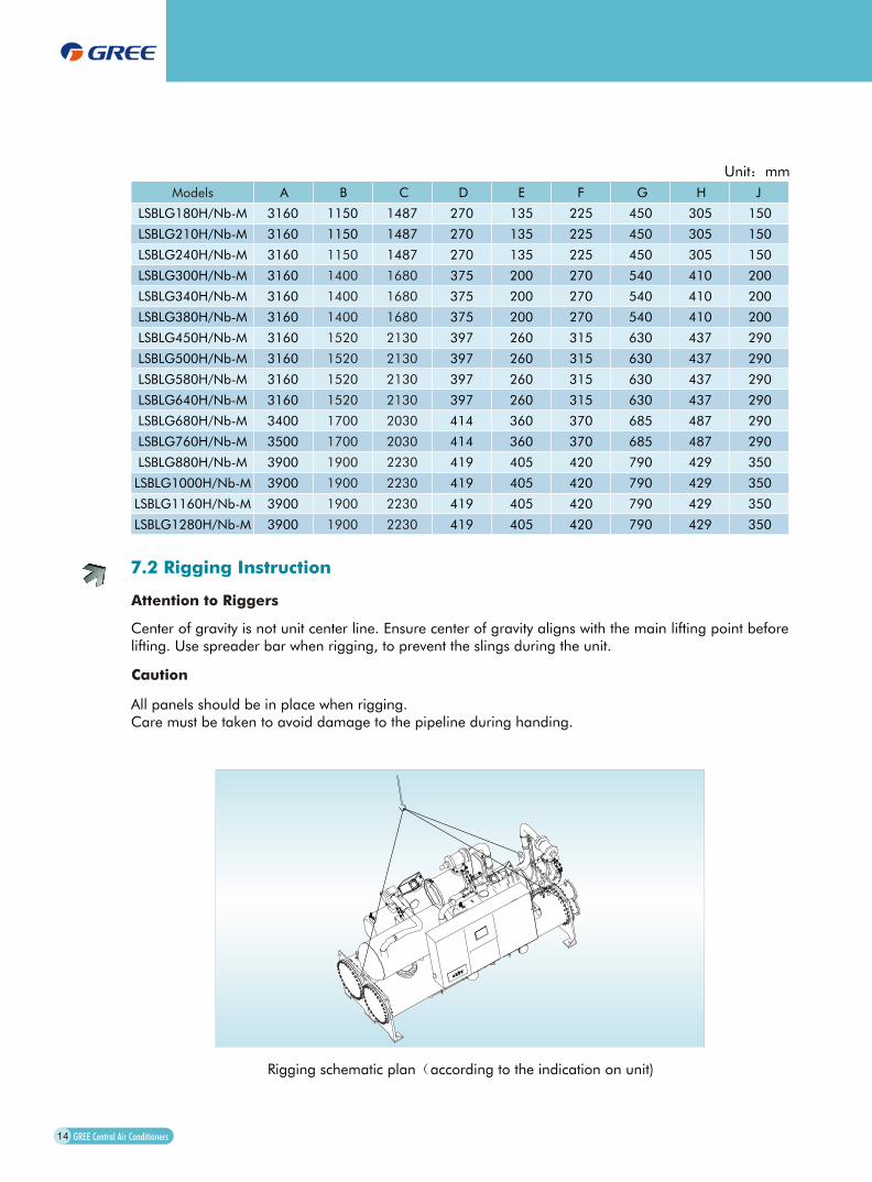
Unit mm
Models A B C D E F G H J
LSBLG180H/Nb-M 3160 1150 1487 270 135 225 450 305 150
LSBLG210H/Nb-M 3160 1150 1487 270 135 225 450 305 150
LSBLG240H/Nb-M 3160 1150 1487 270 135 225 450 305 150
LSBLG300H/Nb-M 3160 1400 1680 375 200 270 540 410 200
LSBLG340H/Nb-M 3160 1400 1680 375 200 270 540 410 200
LSBLG380H/Nb-M 3160 1400 1680 375 200 270 540 410 200
LSBLG450H/Nb-M 3160 1520 2130 397 260 315 630 437 290
LSBLG500H/Nb-M 3160 1520 2130 397 260 315 630 437 290
LSBLG580H/Nb-M 3160 1520 2130 397 260 315 630 437 290
LSBLG640H/Nb-M 3160 1520 2130 397 260 315 630 437 290
LSBLG680H/Nb-M 3400 1700 2030 414 360 370 685 487 290
LSBLG760H/Nb-M 3500 1700 2030 414 360 370 685 487 290
LSBLG880H/Nb-M 3900 1900 2230 419 405 420 790 429 350
LSBLG1000H/Nb-M 3900 1900 2230 419 405 420 790 429 350
LSBLG1160H/Nb-M 3900 1900 2230 419 405 420 790 429 350
LSBLG1280H/Nb-M 3900 1900 2230 419 405 420 790 429 350
7.2 Rigging Instruction
Attention to Riggers
Center of gravity is not unit center line. Ensure center of gravity aligns with the main lifting point before lifting. Use spreader bar when rigging, to prevent the slings during the unit.
Caution
All panels should be in place when rigging.Care must be taken to avoid damage to the pipeline during handing.
Rigging schematic plan according to the indication on unit)
14

7.3 Mounting Location
Mounting location schematic plan
Shock pad(Self-supply by consumer)
Back
Front
RightLeft
[Front of the unit]
Gutter
Footing of the unit
Foundion bolt M18(Self-supply by consumer)
Micro-stone concrete C300#
(Secondary pour)
concrete C300#
Compace soil
Installation plane
10
0
15
Unit mm
Models A M K
LSBLG180H/Nb-M
LSBLG210H/Nb-M
LSBLG240H/Nb-M
LSBLG300H/Nb-M
LSBLG340H/Nb-M
LSBLG380H/Nb-M
LSBLG450H/Nb-M
LSBLG500H/Nb-M
LSBLG580H/Nb-M
LSBLG640H/Nb-M
LSBLG680H/Nb-M
LSBLG760H/Nb-M
LSBLG880H/Nb-M
LSBLG1000H/Nb-M
LSBLG1160H/Nb-M
LSBLG1280H/Nb-M
3160
3160
3160
3160
3160
3160
3160
3160
3160
3160
3400
3400
3900
3900
3900
3900
1350
1350
1350
1600
1600
1600
1720
1720
1720
1720
1900
1900
2000
2000
2000
2000
B
1150
1150
1150
1400
1400
1400
1520
1520
1520
1520
1700
1700
1900
1900
1900
1900
D
2630
2630
2630
2630
2630
2630
2630
2630
2630
2630
2830
2830
3330
3330
3330
3330
740
740
740
920
920
920
1100
1100
1100
1100
1210
1210
1420
1420
1420
1420
Flooded Screw Chiller Technical Sales Guide
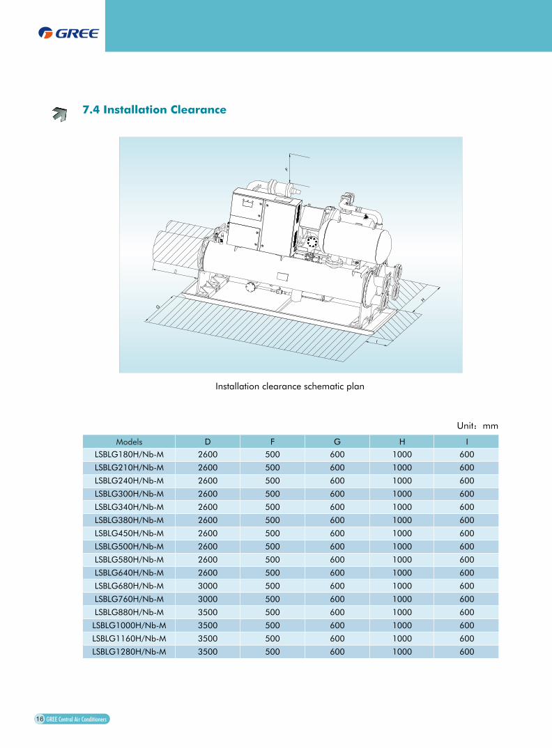
7.4 Installation Clearance
I
G
H
F
Installation clearance schematic plan
Unit mm
Models D F G H I
LSBLG180H/Nb-M 2600 500 600 1000 600
LSBLG210H/Nb-M 2600 500 600 1000 600
LSBLG240H/Nb-M 2600 500 600 1000 600
LSBLG300H/Nb-M 2600 500 600 1000 600
LSBLG340H/Nb-M 2600 500 600 1000 600
LSBLG380H/Nb-M 2600 500 600 1000 600
LSBLG450H/Nb-M 2600 500 600 1000 600
LSBLG500H/Nb-M 2600 500 600 1000 600
LSBLG580H/Nb-M 2600 500 600 1000 600
LSBLG640H/Nb-M 2600 500 600 1000 600
LSBLG680H/Nb-M 3000 500 600 1000 600
LSBLG760H/Nb-M 3000 500 600 1000 600
LSBLG880H/Nb-M 3500 500 600 1000 600
LSBLG1000H/Nb-M 3500 500 600 1000 600
LSBLG1160H/Nb-M 3500 500 600 1000 600
LSBLG1280H/Nb-M 3500 500 600 1000 600
16
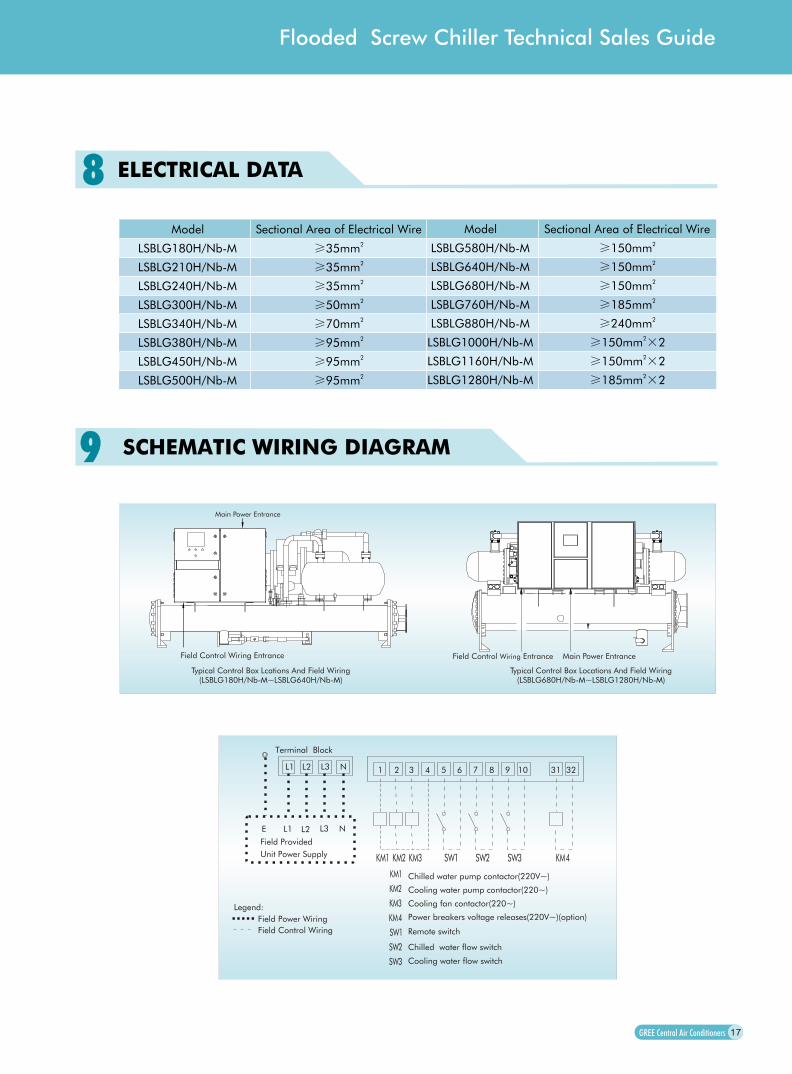
Field Control Wiring Entrance Main Power Entrance
Typical Control Box Locations And Field Wiring
Main Power Entrance
Field Control Wiring Entrance
Typical Control Box Lcations And Field Wiring
(LSBLG680H/Nb ~LSBLG1280H/Nb )-M -M (LSBLG180H/Nb ~LSBLG640H/Nb ) -M -M
1 2 3 4 5 6 7 8 9 10 31 32
1 2 3 1 2 3 4
1
2
3
4
1
2
3
Chilled water pump contactor(220V~)
Cooling water pump contactor(220~)
Cooling fan contactor(220~)
Cooling water flow switch
Chilled water flow switch
,Power breakers voltage releases(220V~)(option)
Remote switch
L1 L2 L3 N
L1 L2 L3 NE
Terminal Block
Field Provided
Unit Power Supply
Legend:
Field Power Wiring
Field Control Wiring
99 SCHEMATIC WIRING DIAGRAM
17
88Model Sectional Area of Electrical Wire
LSBLG180H/Nb-M 235mm
LSBLG210H/Nb-M 235mm
LSBLG240H/Nb-M 235mm
LSBLG300H/Nb-M 250mm
LSBLG340H/Nb-M 270mm
LSBLG380H/Nb-M 295mm
LSBLG450H/Nb-M 295mm
LSBLG500H/Nb-M 295mm
LSBLG580H/Nb-M 2150mm
LSBLG640H/Nb-M 2150mm
LSBLG680H/Nb-M 2150mm
LSBLG760H/Nb-M 2185mm
LSBLG880H/Nb-M 2240mm
LSBLG1000H/Nb-M 2150mm 2
LSBLG1160H/Nb-M 2150mm 2
LSBLG1280H/Nb-M 2185mm 2
Model
ELECTRICAL DATA
Flooded Screw Chiller Technical Sales Guide
Sectional Area of Electrical Wire

APPLICATION DATA111111.1 Work Range
Chilled water Cooling water
Leaving water temperature
Temperature difference of outlet and inlet water( / )
Leaving water temperature
Temperature difference of outlet and inlet water( / )
11.2 Installation Footing
a. The installation footing is required with concrete or steel structure,can bear the Operation Weight of
the unit, with a level upper plane, and preform gutter.
b. According to Mounting Location schematic plan, place steel plate and shock pad exactly on the
installation footing, proceed secondary pour after the unit and foundation bolt is placed. The
foundation bolt is out about 100 mm of installation plane usually.
11.3 Installation Clearance
a. Need to perform installation , operation and maintenance spacing .
b. Ensure the unit keep out of insolation and rain away from fire , combustibles, corrosive gas
and discharge gas; preform ventilation spacing; should have suitable measure to reduce
noise and shock.
18
1010After press startup button, the unit will be started-up after controls detect all inputed signals are normal.
controls auto control compressor startup, capacity adjust and shutdown through the temperature of
chilled in water detected; auto control the step of electrical expanding valve through degree of
superheat temperature detected; auto prevent the chilled of water in evaporator to be frostbite
through the prevent frostbite temperature detected; auto control startup or shutdown of cooling fan
tower through the temperature of cooling in water detected; auto control overheat of the cooling water
in condenser through the temperature of cooling out water detected; auto adjust the capacity of
compressor through the press of evaporator and condense detected, so the unit can work in safe state
once compressor startup, besides comes protective signals , operating time should be at least 6
min(adjustable),although the temperature of chilled in water has reached unload shutdown
temperature after compressor stop, unit should be re-startup after at least 10 min(adjustable).
after unit startup, firstly open chilled water pump, then open cooling water pump, and then open the
cooling fan tower, at last control the startup or shutdown of compressor, adjust the capacity
accordingto chilled in water.
When unit shutdown, firstly shut down compressor, then close cooling fan tower, and then close
cooling water pump, at last close chilled water pump.
MICROPROCESSOR CONTROLLER
2.5 8 36.5 46.45 15 41 59 22 42 71.6 107.6 3.5 8 38.5 46.4