FlightDEK-D180 Conversion to SkyView Guide€¦ · D10 and D100 Series Conversion To SkyView Guide...
44
D10 and D100 Series Conversion To SkyView Guide – Rev D Page 1 D10 1 / D100 2 Series to SkyView Conversion Guide This product is not approved for installation in type certificated aircraft Revision D, January 2014 Supplement to Dynon SkyView System Installation Guide Revision N (and later) and Reflects system configuration in effect as of Firmware v5.1, January 2013 (and later) and EMS Sensor Definitions File 5/29/13 Release (and later) Copyright © 2013-2014 by Dynon Avionics, Inc. Permission to print this manual is granted to third parties. 1 EFIS-D6, EFIS-D10A, EMS-D10 2 EFIS-D60, EFIS-D100, EMS-D120, FlightDEK-D180
Transcript of FlightDEK-D180 Conversion to SkyView Guide€¦ · D10 and D100 Series Conversion To SkyView Guide...
D10 and D100 Series Conversion To SkyView Guide – Rev D Page 1
D101 / D1002 Series to SkyView Conversion Guide
This product is not approved for installation in type certificated aircraft
Revision D, January 2014
Supplement to Dynon SkyView System Installation Guide Revision N (and later) and
Reflects system configuration in effect as of Firmware v5.1, January 2013 (and later) and
EMS Sensor Definitions File 5/29/13 Release (and later)
Copyright © 2013-2014 by Dynon Avionics, Inc.
Permission to print this manual is granted to third parties.
1 EFIS-D6, EFIS-D10A, EMS-D10
2 EFIS-D60, EFIS-D100, EMS-D120, FlightDEK-D180

D10 and D100 Series Conversion To SkyView Guide – Rev D Page 2
Contact Information
Dynon Avionics, Inc. 19825 141
st Place NE
Woodinville, WA 98072 Phone: 425-402-0433 - 8:00 AM – 5:00 PM (Pacific Time) Monday – Friday Dynon Technical Support available 7:00 AM–5:00 PM (Pacific Time) Monday – Friday Dynon Technical Support email – [email protected] Fax: 425-984-1751
Dynon Avionics offers online sales, extensive support, and frequently updated information on its products via its Internet sites:
www.dynonavionics.com –Dynon Avionics primary web site; including:
docs.dynonavionics.com – Current and archival documentation.
downloads.dynonavionics.com – Software downloads.
support.dynonavionics.com – Support resources.
store.dynonavionics.com – Dynon’s secure online store for purchasing all Dynon products 24 hours a day.
wiki.dynonavionics.com – Dynon Avionics’ Documentation Wiki provides enhanced, extended, frequently updated online documentation contributed by Dynon employees and customers.
forum.dynonavionics.com – Dynon Avionics’ Internet forum where Dynon customers can interact and receive Dynon technical support outside of telephone support hours. A key feature of the forum is that it allows the exchange of diagrams, photos, and other types of files.
newsletter.dynonavionics.com – Sign up for Dynon’s email newsletter.
blog.dynonavionics.com – Dynon’s blog where you can find new and interesting Dynon-related content.
register.dynonavionics.com – Register your Dynon Avionics product.
license.dynonavionics.com – Redeem certificates for navigation mapping software, synthetic vision, and other features for license codes that add new functionality to your SkyView system.
Copyright
2013-2014 Dynon Avionics, Inc. All rights reserved. No part of this manual may be reproduced, copied, transmitted, disseminated or stored in any storage medium, for any purpose without the express written permission of Dynon Avionics. Dynon Avionics hereby grants permission to download a single copy of this manual and of any revision to this manual onto a hard drive or other electronic storage medium to be viewed for personal use, provided that such electronic or printed copy of this manual or revision must contain the complete text of this copyright notice and provided further that any unauthorized commercial distribution of this manual or any revision hereto is strictly prohibited.
Information in this document is subject to change without notice. Dynon Avionics reserves the right to change or improve its products and to make changes in the content without obligation to notify any person or organization of such changes. Visit the Dynon Avionics website (www.dynonavionics.com) for current updates and supplemental information concerning the use and operation of this and other Dynon Avionics products.

D10 and D100 Series Conversion To SkyView Guide – Rev D Page 3
Limited Warranty Dynon Avionics warrants this product to be free from defects in materials and workmanship for three years from date of shipment. Dynon Avionics will, at its sole option, repair or replace any components that fail in normal use. Such repairs or replacement will be made at no charge to the customer for parts or labor performed by Dynon Avionics. The customer is, however, responsible for any transportation cost and any costs that are incurred while removing, reinstalling, or troubleshooting the product. This warranty does not cover failures due to abuse, misuse, accident, improper installation or unauthorized alteration or repairs.
THE WARRANTIES AND REMEDIES CONTAINED HEREIN ARE EXCLUSIVE, AND IN LIEU OF ALL OTHER WARRANTIES EXPRESSED OR IMPLIED, INCLUDING ANY LIABILITY ARISING UNDER WARRANTY OF MERCHANTABILITY OR FITNESS FOR A PARTICULAR PURPOSE, STATUTORY OR OTHERWISE. THIS WARRANTY GIVES YOU SPECIFIC LEGAL RIGHTS, WHICH MAY VARY FROM STATE TO STATE AND IN COUNTRIES OTHER THAN THE USA.
IN NO EVENT SHALL DYNON AVIONICS BE LIABLE FOR ANY INCIDENTAL, SPECIAL, INDIRECT OR CONSEQUENTIAL DAMAGES, WHETHER RESULTING FROM THE USE, MISUSE OR INABILITY TO USE THIS PRODUCT OR FROM DEFECTS IN THE PRODUCT. SOME STATES AND COUNTRIES DO NOT ALLOW THE EXCLUSION OF INCIDENTAL OR CONSEQUENTIAL DAMAGES, SO THE ABOVE LIMITATIONS MAY NOT APPLY TO YOU.
Dynon Avionics retains the exclusive right to repair or replace the instrument or firmware or offer a full refund of the purchase price at its sole discretion. SUCH REMEDY SHALL BE YOUR SOLE AND EXCLUSIVE REMEDY FOR ANY BREACH OF WARRANTY.
These instruments are not intended for use in type certificated aircraft at this time. Dynon Avionics makes no claim as to the suitability of its products in connection with FAR 91.205.
Dynon Avionics’ products incorporate a variety of precise, sensitive electronics. SkyView products do not contain any field/user-serviceable parts. Units found to have been taken apart may not be eligible for repair under warranty. Additionally, once a Dynon Avionics unit is opened up, it is not considered airworthy and must be serviced at the factory.
D10 and D100 Series Conversion To SkyView Guide – Rev D Page 4
Revision History Revision Revision Date Description
D January, 2014 Updated guidance that SkyView does not support
pressure altitude output to certain transponders that are supported in Dynon EFIS units. (Page 13)
C September 2013
Updated guidance for use of capacitive fuel level sensors (voltage output) SV-EMS-220 Pins 20 and 21.
Minor terminology revisions on SV-EMS-220 connected sensor descriptions.
Updated all references to SV-EMS-220 Pin 23 to reflect that it is now a General Purpose Input, Type C (was Type A).
Removed Page 45 (this page intentionally left blank)
B August 2013
Removed guidance for SkyView COM Radio. Full information on SkyView SV-COM-C25 is now available.
Added EMS Sensor Types conversion to SkyView Sensor Types.
Updated SV-EMS-220 C37 P24 to mention GRT CS-01 rewiring required.
Corrected that MS28034-3 sensor is not supported in SkyView (it is supported).
Additional non-Dynon sensors not supported in SkyView.
Updated guidance on SV-EMS-220 Pin 23; enabled as an Enhanced General Purpose Input Pin after installing the June 2013 (or later) version of the Engine Sensor Definition File.
A January 2013 Initial release
D10 and D100 Series Conversion To SkyView Guide – Rev D Page 5
Contents
Introduction to this Guide .............................................................................................................. 6
Major Differences between Dynon Avionics EFIS, EMS, and SkyView ........................................... 8
SkyView Compatibilities with Dynon Avionics EFIS and EMS Systems ......................................... 11
SkyView Incompatibilities with Dynon Avionics EFIS and EMS Systems ...................................... 12
SkyView Mechanical Installation Considerations ......................................................................... 14
General Electrical Installation Considerations .............................................................................. 15
Guidelines for Conversion of Dynon Avionics EFIS Harness to SkyView Display SV-HARNESS-D37 ............................................................................................... 16
Guidelines for Connection of Installed OAT to SV-ADAHRS-200/201 OAT Input ......................... 19
Guidelines for Conversion of EMS Main Sensor Harness to SkyView SV-EMS-220 Main Sensor Harness ................................................................................. 19
Guidelines for Conversion of Dynon Avionics EMS CHT/EGT Harness to SkyView SV-EMS-220 CHT/EGT Harness ....................................................................................... 29
EMS Sensor Type Conversion to SkyView Sensor Type ................................................................ 30
Guidelines for Conversion of HS34 HSI Expansion ModuleD25 Male Connector to SV-HARNESS-D37 and SkyView SV-EMS-220 Main Sensor Harness ......................................... 33
Guidelines for Conversion of HS34 HSI Expansion Module D25 Female Connector to SV-HARNESS-D37 and SkyView SV-EMS-220 Main Sensor Harness ............................................. 40
Guidelines for Conversion of AP74 Dedicated Autopilot Interface Module to SV-HARNESS-D37 .......................................................................................................................... 42
Guidelines for Conversion of Dynon Avionics Autopilot Servos ................................................... 43
Guidelines for Conversion of Accessories ..................................................................................... 44
D10 and D100 Series Conversion To SkyView Guide – Rev D Page 6
Introduction to this Guide
This guide provides an overview of the installation of a Dynon Avionics SkyView system as a conversion from an installed Dynon Avionics EFIS system: EFIS-D6, EFIS-D10A, EFIS-D60, EFIS-D100, and the EFIS portion of the Dynon Avionics FlightDEK-D180.
This guide provides an overview of the installation of a Dynon Avionics SkyView system as a conversion from an installed Dynon Avionics EMS system: EMS-D10, EMS-D120, and the EMS portion of the Dynon Avionics FlightDEK-D180.
There is very high degree of commonality of wiring between Dynon Avionics’ various EFIS units. Similarly, there is very high degree of commonality regarding wiring between Dynon Avionics various EMS units. In this guide, any significant differences between specific units, such as different pin functionality, that would affect conversion to SkyView, is noted.
Because of this high degree of commonality between the various EFIS units, the term EFIS will be used to refer to connections related to the EFIS-D6, EFIS-10A, EFIS-D60, EFIS-D100, and the EFIS portion of the FlightDEK-D180.
Because of this high degree of commonality between the various EMS units, the term EMS will be used to refer to connections related to the EMS-D10, EMS-D120, and the EMS portion of the FlightDEK-D180.
It is intended that this guide is distributed electronically (PDF format) and the installer print out only the sections that are applicable. For example, systems that do not include an HS34 won’t need to print out the HS34 section.
This guide is a supplement to, not a replacement for, the current Dynon SkyView System Installation Guide, which is updated concurrent with every major SkyView firmware update. This guide assumes that you will have access to the current version of the SkyView System Installation Guide, which this guide will frequently defer to. All of Dynon Avionics current manuals are available for download at: http://docs.dynonavionics.com.
It is the installer’s responsibility to conform to industry standards and best practices when applicable.
This guide is not intended to assist in conversion of a Special – Light Sport Aircraft (S-LSA) from a Dynon Avionics EFIS or Dynon Avionics EMS to a Dynon SkyView System. Such conversions can only be performed with explicit and airplane-specific instructions from the S-LSA aircraft manufacturer, and only by those who are qualified to work on the aircraft.
Because of the standardized wiring system in a Van’s Aircraft RV-12, this guide will be of limited use in an RV-12 SkyView conversion. To convert an RV-12 to SkyView, Van’s Aircraft offers conversion kits, instructions, and support.
Conversion to SV-EMS-221, used only with installation of a Rotax 912 iS engine is beyond the scope of a typical Dynon Avionics EMS to SkyView conversion. Detailed installation instructions for SV-EMS-221 with a Rotax 912 iS engine are included in the SkyView System Installation Guide, Revision L and later.

D10 and D100 Series Conversion To SkyView Guide – Rev D Page 7
This guide will be revised as SkyView features evolve. If you have suggestions for this guide, please submit comments via email to: [email protected] with Subject: Conversion To SkyView Guide.
D10 and D100 Series Conversion To SkyView Guide – Rev D Page 8
Major Differences Between Dynon Avionics EFIS, EMS, and SkyView
There is no integration or communication between Dynon Avionics EFIS and EMS units and SkyView
Because of the enhanced capabilities of SkyView, there is no “backwards compatibility” for SkyView systems to be able to communicate or interoperate with a Dynon Avionics EFIS or EMS.
SkyView displays are separate from the flight data sensors
With the exception of the EDC-D10A external magnetometer, a Dynon Avionics EFIS integrates the flight data sensors within the instrument.3 4 In a SkyView system, flight data sensors are contained within the SV-ADAHRS-200 and SV-ADAHRS-201 (hereafter, referred to as SV-ADAHRS-200/201). Similarly, in a Dynon Avionics EMS, the conversion of engine sensor signals to data is done in the instrument; in a SkyView system, that conversion is performed in the SV-EMS-220 module.
Because of this separation of flight sensors from displays, SkyView displays can be mounted in any attitude.
SkyView Network is more sophisticated, redundant, with power vs. DSAB
SkyView Network improves on DSAB Network in several ways:
SkyView Network data rate is significantly faster than DSAB Network.
SkyView Network incorporates redundant data pairs with failover.
SkyView Network provides a power bus to power network modules, and includes a secondary power bus.
Data from modules can be used on any SkyView display.
Up to three SkyView displays can be used in a SkyView Network.
SkyView Network wiring requires twisted pair wiring for the data pairs.
Other SkyView data communications
Devices that communicate via RS-232 (serial) such as GPS receivers, navigation radios, transponders, etc. are connected to the serial ports on all SkyView displays, not SkyView Network.
SkyView displays exchange some data over an Ethernet cable (in addition to exchanging data over SkyView Network).
Serial and Ethernet wiring are explained in detail in the SkyView Installation Guide in the section Electrical Installation Considerations.
3 Exception 1 – Magnetic heading is determined by the external EDC-D10A remote compass.
4 Exception 2 – In a SkyView system, the Outside Air Temperature (OAT) probe connects to the SV-ADAHRS-
200/201.
D10 and D100 Series Conversion To SkyView Guide – Rev D Page 9
Redundancy / failover is integral to SkyView
A SkyView system is more network-centric and redundant than an EFIS and EMS. Many of the specific recommendations for installing a SkyView system focus on maintaining redundancy.
SkyView is designed to minimize single point failures, provided redundant units are installed. Examples:
If a SkyView display fails, all flight and engine data can be displayed on another SkyView display.
If the SV-ADAHRS-200 fails, the SV-ADAHRS-201 will automatically be used for flight data. Data from multiple ADAHRS modules are continuously cross-checked against each other.
SkyView Network includes redundant data buses and redundant power lines5. See the SkyView System Installation Guide for a complete explanation of installing and equipping for redundancy and failover.
For redundancy failover, serial devices such as transponders must be connected to all SkyView displays. SkyView displays have special circuitry and software that allows serial devices to be connected to more than one serial “transmitter” (not normally possible). If a SkyView display fails, another SkyView display takes over communications with all serial devices.
Redundancy extends to having independent, individual OAT probes for both the SV-ADAHRS-200 and SV-ADAHRS-201.
Exceptions:
1) Autopilot servos have SkyView Network redundant data bus, but not redundant power – they receive power directly from the plane’s power bus.
2) There is no redundancy for the SV-EMS-220; if the SV-EMS-220 fails, there is no engine monitoring capability.
GPS is integral to SkyView
In an EFIS, connection to a GPS receiver is optional. In a SkyView system, connection to a GPS receiver is required. GPS is integral to SkyView operation, including:
Time is automatically set from GPS6; time cannot be set manually.
During Compass Calibration, GPS position data is used to automatically calculate magnetic inclination and intensity. Unlike with an EFIS compass calibration, it’s no longer required to consult a cryptic web page for localized magnetic field data.
GPS position data is required to display Map and Synthetic Vision
Primary flight display fails over to use GPS ground speed in the event of zero airspeed.
Dynon strongly recommends the installation of its SV-GPS-250 in a SkyView system because it offers numerous advantages versus panel-mounted or portable GPS units:
5 As of firmware v6.2, monitoring and failover to the redundant power bus has not yet been implemented.
6 GPS must transmit NMEA data format, not Aviation data format
D10 and D100 Series Conversion To SkyView Guide – Rev D Page 10
The SV-GPS-250 transmits position updates 5x/second (5 Hz), so the airplane movement is displayed smoothly on SkyView’s high resolution terrain and map pages. Most other GPS units only output data 1x/second.
At $200, the SV-GPS-250 is a relative bargain; inexpensive enough to have multiple units installed (especially feasible if multiple SkyView displays are installed).
The SV-GPS-250 is an integrated antenna and receiver – no difficult routing and termination of coaxial cable, only four 22 AWG wires.
The SV-GPS-250 is easily connected to a (or multiple) SkyView display(s). A serial port and dedicated power and ground wires / pins for the SV-GPS-250 are provided on SkyView displays. Power for the SV-GPS-250 is provided by SkyView display(s) so the SV-BAT-320 backup battery also provides backup power to the GPS-250.
Because SV-GPS-250 is (optimally) mounted on the fuselage, it provides maximum “visibility” to available GPS satellites.
The SV-GPS-250 receives WAAS transmissions7 and transmits industry-standard NMEA sentences.
If only one SV-GPS-250 is installed, it’s recommended (and well-supported) to connect a single SV-GPS-250 to multiple SkyView displays in parallel for failover redundancy.
SkyView battery backup
Each SkyView display supports an (external) backup battery – SV-BAT-320. Although the SV-BAT-320 is optional, it is highly recommended. By providing backup power to a SkyView display, power is also being supplied to the SkyView network. Devices that draw power directly from the SkyView Network such as the SV-ADAHRS-200/201 and SV-EMS-220 are thus also “battery backed”. Because the SV-GPS-250 has its own dedicated power connection on a SkyView display, the SV-GPS-250 is also “battery backed”. Each SkyView display should have its own SV-BAT-320 installed and will then “share the load” of providing backup battery power into the SkyView Network and SkyView Network devices.
Easier software / data updates
Instead of connecting a laptop computer with a serial port to a Dynon Avionics EFIS or EMS, SkyView is updated by downloading data from an Internet-connected computer onto a USB Flash Drive (memory stick), then bringing that USB Flash Drive to the SkyView display.
More flexible engine monitoring
Dynon’s EMS units had three general purpose inputs; the SkyView SV-EMS-220 has thirteen general purpose inputs, and adds two voltmeter inputs, built-in differential fuel flow measurement8, compatibility with low-voltage tachometer signals, and much more.
7 While the SV-GPS-250 does receive Wide Area Augmentation System (WAAS) signals in addition to GPS
signals, it is not a Certified WAAS GPS receiver that would be included as part of an IFR approach-capable GPS
system. 8 With the inclusion of a second fuel flow sensor for monitoring return fuel flow.
D10 and D100 Series Conversion To SkyView Guide – Rev D Page 11
SkyView Compatibilities with Dynon Avionics EFIS and EMS Systems
SkyView is compatible with the following Dynon accessories that may be part of a Dynon Avionics EFIS or EMS system:
All engine monitoring sensors sold by Dynon – CHT, EGT, oil temp, oil pressure, fuel pressure, amps, fuel flow, etc.
Autopilot servos9 10
Angle of Attack / Pitot Probe / Boom (heated and unheated versions)
Capacitance to Voltage Converter
EMS Wiring Harness11
Encoder Serial-to-Gray Code Converter Module
OAT Probe for EDC-D10A – 100433-001 (sold since 2005) and OAT Probe for EMS – 100433-00012
9 For servos to be compatible with SkyView requires the Dynon Avionics EFIS must be at least firmware v5.2. 10
To communicate with servos, a Dynon Avionics EFIS’ DSAB used only one of the servo’s two communications buses (Blue and Green wires). SkyView Network implements the second communications bus on a servo – Blue+Green wires, and White/Blue+White/Green wires. 11
Some modifications required to work with SkyView 12
Some modifications required to work with SkyView
D10 and D100 Series Conversion To SkyView Guide – Rev D Page 12
SkyView Incompatibilities with Dynon Avionics EFIS and EMS Systems
SkyView is not compatible with the following Dynon accessories that may be part of a Dynon Avionics EFIS or EMS system:
AP74 – SkyView does not support the AP74 Autopilot Control Panel. SkyView has eight pushbuttons and two knobs / joysticks, so Autopilot control is as easy with SkyView as it is with the AP74. For example, the heading bug can easily be adjusted via a knob twist, which on a Dynon Avionics EFIS required the installation of an AP74 or HS34.
EDC-D10A – SkyView does not use the EDC-D10A. In SkyView, the magnetic heading sensor is integrated into the SV-ADAHRS-200/201.
EFIS Wiring Harness – SkyView does not use the same EFIS 25-pin “Primary Wiring Harness” as the Dynon Avionics EFIS.
HS34 – SkyView does not support the HS34 HSI Expansion Module. For ARINC-429 functions of the HS34, SkyView uses the SV-ARINC-429 module. For serial port connections to the HS34, use the serial port inputs and serial port outputs on the SkyView display(s). The functionality of the knobs and buttons on the HS34 are integrated into the SkyView display.
The Analog Resolver, DME, Marker, etc. inputs and outputs present on the HS34 are not available in SkyView.
Internal Li-Ion Backup Battery – SkyView is not compatible with the (internal) backup battery used in Dynon Avionics EFIS units. SkyView displays use a completely different, external backup battery (SV-BAT-320).
OAT Probe for EDC-D10A (older) – SkyView is not compatible with the Dynon 100240-000 OAT (Type 1, no black band on the cable). This OAT probe has not been sold since 2004.
Mounting Trays – SkyView does not use mounting trays13, so after removing the Dynon Avionics EFIS and/or EMS, remove any mounting trays, including the mounting trays for the AP74 and HS34.
13
Exception – SV-XPNDR-261/262 has a mounting tray.
D10 and D100 Series Conversion To SkyView Guide – Rev D Page 13
Third Party Transponders – The following transponders may be installed in a Dynon Avionics EFIS installation, but are not supported in SkyView. SkyView does not output pressure altitude data in these formats:
Magellan (EFIS Serial Altitude Format 2, 1200 baud)
Northstar, Garmin (EFIS Serial Altitude Format 3, 2400 baud)
Third Party Pressure Sensors – The following pressure sensors may be installed in a Dynon Avionics EMS installation, but are not supported in SkyView:
GRT LPS-02 (fuel)
GRT MAP-01 / MAP-02 (manifold)
Third Party Temperature Sensors – The following temperature sensors may be installed in a Dynon Avionics EMS installation, but are not supported in SkyView:
Chevrolet LS7 (pre-installed, coolant and oil)
GRT CARB-01 (carburetor)
GRT OAT-01 (general purpose, outside air)
MGL 2-wire (oil)
UMA 1B1 (1/8-27 NPT) (oil)
UMA 1B3 (5/8-18 UNF) (oil)
Westach 399S7 (1/8-27 NPT) (oil)
Westach 299S9 (5/8-18 UNF) (oil)
D10 and D100 Series Conversion To SkyView Guide – Rev D Page 14
SkyView Mechanical Installation Considerations
Complete, detailed mechanical installation details, including dimensioned mechanical drawings, for installing a SkyView system are in the SkyView System Installation Guide.
The SV-D700 (7” SkyView display) is slightly larger than the mounting bracket for a Dynon Avionics EFIS-D60, EFIS-D100, EMS-D120, or FlightDEK-D180, so some panel rework will be required to install an SV-D700 in place of those units.
While the SkyView displays are not as deep as the units mentioned above, the SkyView displays include a heat sink with fans which require free space for air to circulate.
The SV-BAT-320 backup battery for a SkyView display is external. An SV-BAT-320 can only power one SkyView display (and any modules connected via SkyView network). If you wish to keep two SkyView displays active in the event of loss of Avionics power, each SkyView display requires its own SV-BAT-320. The SV-BAT-320 is connected to a SkyView Display via a 24” wire (which should not be extended), so reserve room to mount the SV-BAT-320 very close to the SkyView Display.
The SV-ADAHRS-200/201 must be mounted within in a specific “box” centered around the airplane’s center of gravity and must be installed in an area that is magnetically benign (like the EDC-D10A). The SV-ADAHRS-200/201 also requires pitot, static, and (optional) AOA pneumatic lines to be connected. Unlike the EDC-D10A, the SV-ADAHRS-200/201 cannot be mounted at the extreme tail or a wingtip (these locations are typically “outside the box”).
D10 and D100 Series Conversion To SkyView Guide – Rev D Page 15
General Electrical Installation Considerations
Complete electrical installation details for installing a SkyView system are in the SkyView System Installation Guide.
SkyView systems require more electrical power (current) than a Dynon Avionics EFIS or EMS system - circuit breakers and main wiring, and perhaps even alternator / generator and batteries may need to be upgraded. Specific power requirements for SkyView units are listed in the SkyView System Installation Guide. Because of the increased power requirements, little of the electrical wiring14 from a Dynon Avionics EFIS or EMS system can be reused.
Unlike a Dynon EFIS unit, SkyView does not have inputs for secondary (EXTERNAL BACKUP POWER) or tertiary (KEEP ALIVE) power source(s). Should SkyView lose power to its primary power input pins, a SkyView display will operate from its backup battery (SV-BAT-320).
To balance current draw on the D-Sub connector’s pins, run both red wires, and both ground wires of the SV-HARNESS-D37 to avionics power and ground, respectively.
Some SkyView modules and accessories receive (redundant, battery-backed15) power via SkyView Network:
SV-ADAHRS-200/201
SV-ARINC-429
SV-EMS-220
SV-GPS-25016
Other modules must have avionics power connected directly:
SV-ADSB-470
SV-COM-C25
SV-XPNDR-261/262
Autopilot Servos
SkyView Network cables are not included with a SkyView display, and must be ordered (or built) separately. Dynon sells pre-assembled and semi-assembled SkyView Network cables of varying lengths, and a kit of wires and connectors for connecting Autopilot servos. Dynon’s SkyView Network cables have the advantage of having pins crimped, some connectors assembled, and the data wires pre-twisted as recommended by Dynon. See Dynon’s Product Ordering Guide and the SkyView System Installation Guide for details on the various SkyView Network cables that are available.
14
Servo power requirements are the same in a Dynon Avionics EFIS system and a SkyView system. 15
If optional SV-BAT-320 battery is installed on at least one SkyView display. 16
Does not actually use SkyView Network. SV-GPS-250 transmits, receives, and is powered from a dedicated serial / power connection on SkyView displays.
D10 and D100 Series Conversion To SkyView Guide – Rev D Page 16
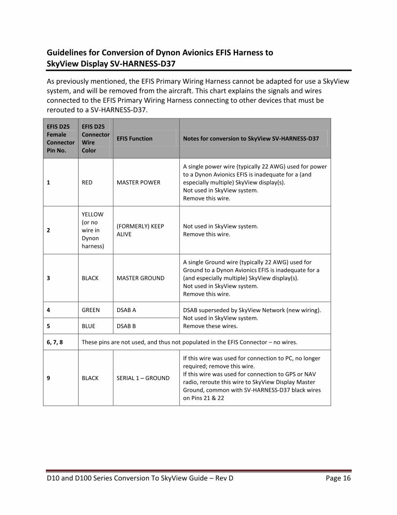
Guidelines for Conversion of Dynon Avionics EFIS Harness to SkyView Display SV-HARNESS-D37
As previously mentioned, the EFIS Primary Wiring Harness cannot be adapted for use a SkyView system, and will be removed from the aircraft. This chart explains the signals and wires connected to the EFIS Primary Wiring Harness connecting to other devices that must be rerouted to a SV-HARNESS-D37.
EFIS D25 Female Connector Pin No.
EFIS D25 Connector Wire Color
EFIS Function Notes for conversion to SkyView SV-HARNESS-D37
1 RED MASTER POWER
A single power wire (typically 22 AWG) used for power to a Dynon Avionics EFIS is inadequate for a (and especially multiple) SkyView display(s). Not used in SkyView system. Remove this wire.
2
YELLOW (or no wire in Dynon harness)
(FORMERLY) KEEP ALIVE
Not used in SkyView system. Remove this wire.
3 BLACK MASTER GROUND
A single Ground wire (typically 22 AWG) used for Ground to a Dynon Avionics EFIS is inadequate for a (and especially multiple) SkyView display(s). Not used in SkyView system. Remove this wire.
4 GREEN DSAB A DSAB superseded by SkyView Network (new wiring). Not used in SkyView system. Remove these wires. 5 BLUE DSAB B
6, 7, 8 These pins are not used, and thus not populated in the EFIS Connector – no wires.
9 BLACK SERIAL 1 – GROUND
If this wire was used for connection to PC, no longer required; remove this wire. If this wire was used for connection to GPS or NAV radio, reroute this wire to SkyView Display Master Ground, common with SV-HARNESS-D37 black wires on Pins 21 & 22

D10 and D100 Series Conversion To SkyView Guide – Rev D Page 17
EFIS D25 Female Connector Pin No.
EFIS D25 Connector Wire Color
EFIS Function Notes for conversion to SkyView SV-HARNESS-D37
10 ORANGE SERIAL 1 – TX
If this wire was used for connection to PC, no longer required; remove this wire. If this wire was used for connection to GPS or NAV radio, reroute this wire to SkyView Display Serial Port TX.
If this wire was used for EFIS Streaming Data, reroute this wire to SkyView Display Serial Port TX.
11 WHITE / ORANGE
EDC-D10A DATA B Not used in SkyView system. Remove this wire.
12 WHITE / BLUE
EDC-D10A POWER Not used in SkyView system. Remove this wire.
13 BLUE / WHITE
SERIAL 2 TX
If this wire was used for transponder (or Dynon 100362-000 Serial-to-Gray Code Encoder Converter Module), reroute this wire to SkyView Display Serial Port TX.
14 This pin is not used, and thus not populated in the EFIS Connector – no wire.
15 No wire (in Dynon harness)
EXTERNAL BACKUP POWER
A single power wire (typically 22 AWG) used for power to a Dynon Avionics EFIS is inadequate for a (and especially multiple) SkyView display(s). Not used in SkyView system. Remove this wire.
16 BLACK (UNUSED) / GND If this wire was used for Ground to an external device, connect to Master Ground, common with SV-HARNESS-D37 black wires on Pins 21 & 22
17 This pin is not used, and thus not populated in the EFIS Connector – no wire.
18 GREEN AUDIO OUT
If this wire was used for audio output, reroute this wire to SkyView display. Because EFIS Audio was mono, connect this wire to both SkyView Display PIN 13 – AUDIO OUTPUT LEFT and PIN 31 – AUDIO OUTPUT RIGHT
If a 10K potentiometer was installed on this to adjust volume, remove it (SkyView has internal volume adjustment).
19, 20 These pins are not used, and thus not populated in the EFIS Connector – no wires.
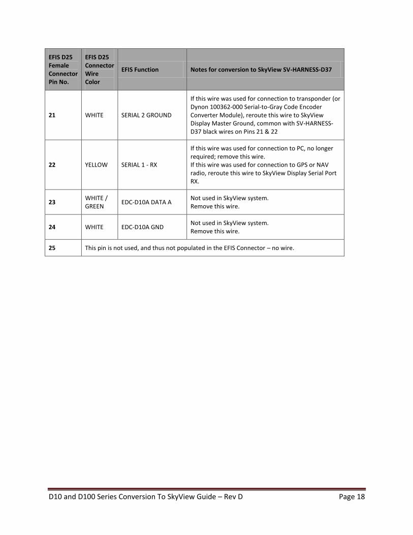
D10 and D100 Series Conversion To SkyView Guide – Rev D Page 18
EFIS D25 Female Connector Pin No.
EFIS D25 Connector Wire Color
EFIS Function Notes for conversion to SkyView SV-HARNESS-D37
21 WHITE SERIAL 2 GROUND
If this wire was used for connection to transponder (or Dynon 100362-000 Serial-to-Gray Code Encoder Converter Module), reroute this wire to SkyView Display Master Ground, common with SV-HARNESS-D37 black wires on Pins 21 & 22
22 YELLOW SERIAL 1 - RX
If this wire was used for connection to PC, no longer required; remove this wire. If this wire was used for connection to GPS or NAV radio, reroute this wire to SkyView Display Serial Port RX.
23 WHITE / GREEN
EDC-D10A DATA A Not used in SkyView system. Remove this wire.
24 WHITE EDC-D10A GND Not used in SkyView system. Remove this wire.
25 This pin is not used, and thus not populated in the EFIS Connector – no wire.
D10 and D100 Series Conversion To SkyView Guide – Rev D Page 19
Guidelines for Connection of Installed OAT to SV-ADAHRS-200/201 OAT Input
It is possible to convert an already-installed Dynon OAT probe that was previously connected to the EDC-D10A, to a SkyView SV-ADAHRS-200 or SV-ADAHRS-201. Instructions for this conversion are in the SkyView System Installation Guide, Chapter 5 – SV-ADAHRS-20X Installation and Configuration, in the section Dynon D10/D100 Series OAT Probes.
Guidelines for Conversion of EMS Main Sensor Harness to SkyView SV-EMS-220 Main Sensor Harness
For a detailed explanation of the full range of capabilities for each pin of the SV-EMS-220 37-pin connector, see these tables and figures in the SkyView System Installation Guide, SV-EMS-220 Installation and Configuration:
● Sensor and Transducer Compatibility Level Key ● SV-EMS-220 Male D37 Pin-to-Sensor Compatibility ● SV-EMS-220 37-pin Main Sensor Harness Female D37 Pin Insertion View (Rear)
D10 and D100 Series Conversion To SkyView Guide – Rev D Page 20
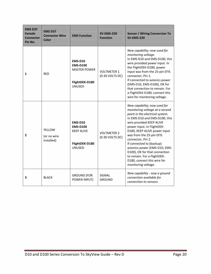
EMS D37 Female Connector Pin No.
EMS D37 Connector Wire Color
EMS Function SV-EMS-220 Function
Sensor / Wiring Conversion To SV-EMS-220
1 RED
EMS-D10 EMS-D100 MASTER POWER
FlightDEK-D180 UNUSED
VOLTMETER 1 (0-30 VOLTS DC)
New capability; now used for monitoring voltage. In EMS-D10 and EMS-D100, this wire provided power input. In the FlightDEK-D180, power input was from the 25-pin EFIS connector, Pin 1. If connected to avionics power (EMS-D10, EMS-D100), OK for that connection to remain. For a FlightDEK-D180, connect this wire for monitoring voltage.
2
YELLOW
(or no wire installed)
EMS-D10 EMS-D100 KEEP ALIVE
FlightDEK-D180 UNUSED
VOLTMETER 2 (0-30 VOLTS DC)
New capability; now used for monitoring voltage at a second point in the electrical system. In EMS-D10 and EMS-D100, this wire provided KEEP ALIVE power input. In FlightDEK-D180, KEEP ALIVE power input was from the 25-pin EFIS connector, Pin 2. If connected to (backup) avionics power (EMS-D10, EMS-D100), OK for that connection to remain. For a FlightDEK-D180, connect this wire for monitoring voltage.
3 BLACK GROUND (FOR POWER INPUT)
SIGNAL GROUND
New capability - now a ground connection available for connection to sensors.
D10 and D100 Series Conversion To SkyView Guide – Rev D Page 21
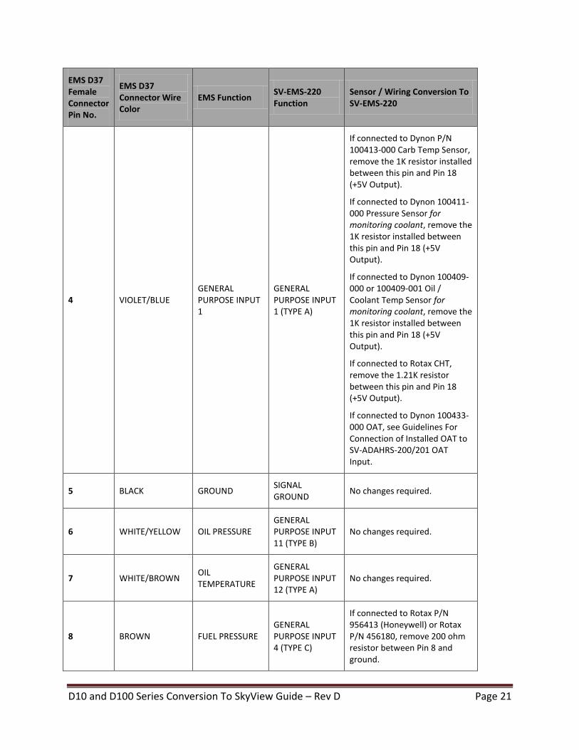
EMS D37 Female Connector Pin No.
EMS D37 Connector Wire Color
EMS Function SV-EMS-220 Function
Sensor / Wiring Conversion To SV-EMS-220
4 VIOLET/BLUE GENERAL PURPOSE INPUT 1
GENERAL PURPOSE INPUT 1 (TYPE A)
If connected to Dynon P/N 100413-000 Carb Temp Sensor, remove the 1K resistor installed between this pin and Pin 18 (+5V Output).
If connected to Dynon 100411-000 Pressure Sensor for monitoring coolant, remove the 1K resistor installed between this pin and Pin 18 (+5V Output).
If connected to Dynon 100409-000 or 100409-001 Oil / Coolant Temp Sensor for monitoring coolant, remove the 1K resistor installed between this pin and Pin 18 (+5V Output).
If connected to Rotax CHT, remove the 1.21K resistor between this pin and Pin 18 (+5V Output).
If connected to Dynon 100433-000 OAT, see Guidelines For Connection of Installed OAT to SV-ADAHRS-200/201 OAT Input.
5 BLACK GROUND SIGNAL GROUND
No changes required.
6 WHITE/YELLOW OIL PRESSURE GENERAL PURPOSE INPUT 11 (TYPE B)
No changes required.
7 WHITE/BROWN OIL TEMPERATURE
GENERAL PURPOSE INPUT 12 (TYPE A)
No changes required.
8 BROWN FUEL PRESSURE GENERAL PURPOSE INPUT 4 (TYPE C)
If connected to Rotax P/N 956413 (Honeywell) or Rotax P/N 456180, remove 200 ohm resistor between Pin 8 and ground.
D10 and D100 Series Conversion To SkyView Guide – Rev D Page 22
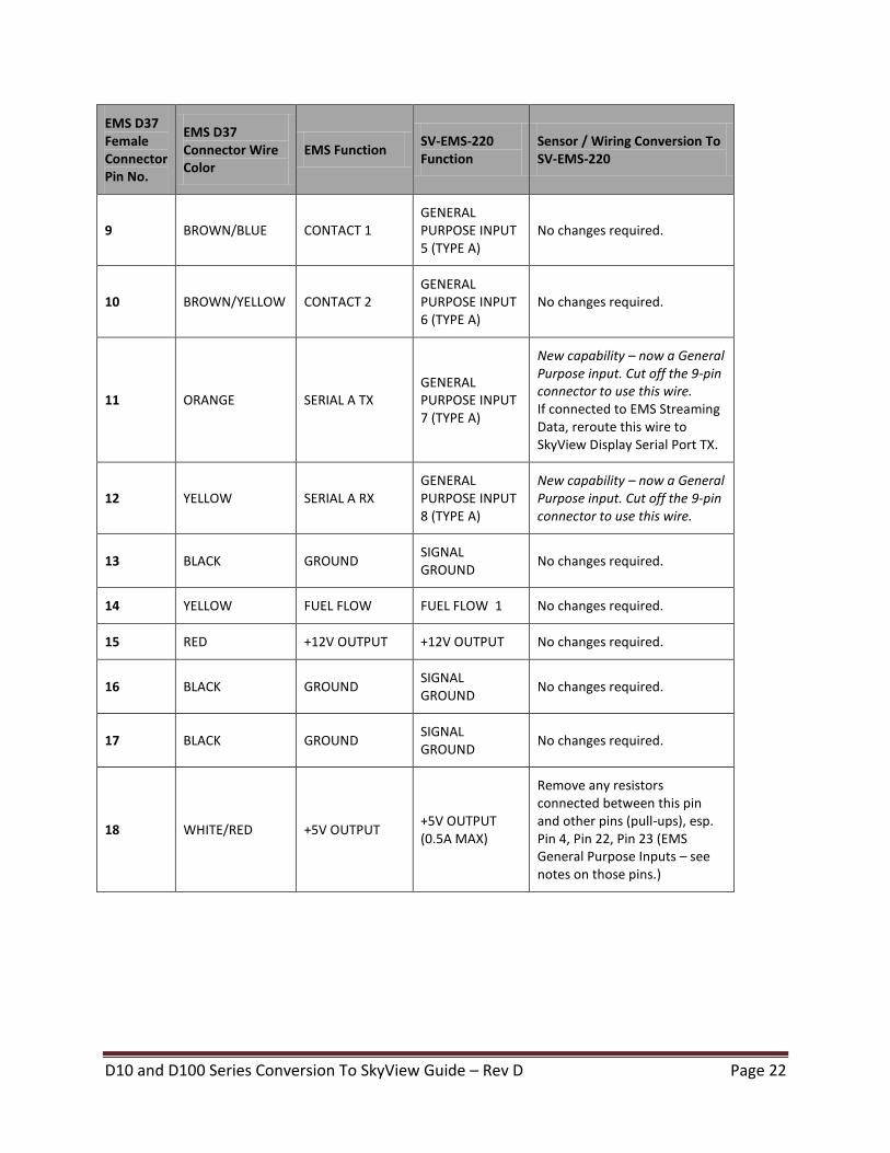
EMS D37 Female Connector Pin No.
EMS D37 Connector Wire Color
EMS Function SV-EMS-220 Function
Sensor / Wiring Conversion To SV-EMS-220
9 BROWN/BLUE CONTACT 1 GENERAL PURPOSE INPUT 5 (TYPE A)
No changes required.
10 BROWN/YELLOW CONTACT 2 GENERAL PURPOSE INPUT 6 (TYPE A)
No changes required.
11 ORANGE SERIAL A TX GENERAL PURPOSE INPUT 7 (TYPE A)
New capability – now a General Purpose input. Cut off the 9-pin connector to use this wire. If connected to EMS Streaming Data, reroute this wire to SkyView Display Serial Port TX.
12 YELLOW SERIAL A RX GENERAL PURPOSE INPUT 8 (TYPE A)
New capability – now a General Purpose input. Cut off the 9-pin connector to use this wire.
13 BLACK GROUND SIGNAL GROUND
No changes required.
14 YELLOW FUEL FLOW FUEL FLOW 1 No changes required.
15 RED +12V OUTPUT +12V OUTPUT No changes required.
16 BLACK GROUND SIGNAL GROUND
No changes required.
17 BLACK GROUND SIGNAL GROUND
No changes required.
18 WHITE/RED +5V OUTPUT +5V OUTPUT (0.5A MAX)
Remove any resistors connected between this pin and other pins (pull-ups), esp. Pin 4, Pin 22, Pin 23 (EMS General Purpose Inputs – see notes on those pins.)
D10 and D100 Series Conversion To SkyView Guide – Rev D Page 23
EMS D37 Female Connector Pin No.
EMS D37 Connector Wire Color
EMS Function SV-EMS-220 Function
Sensor / Wiring Conversion To SV-EMS-220
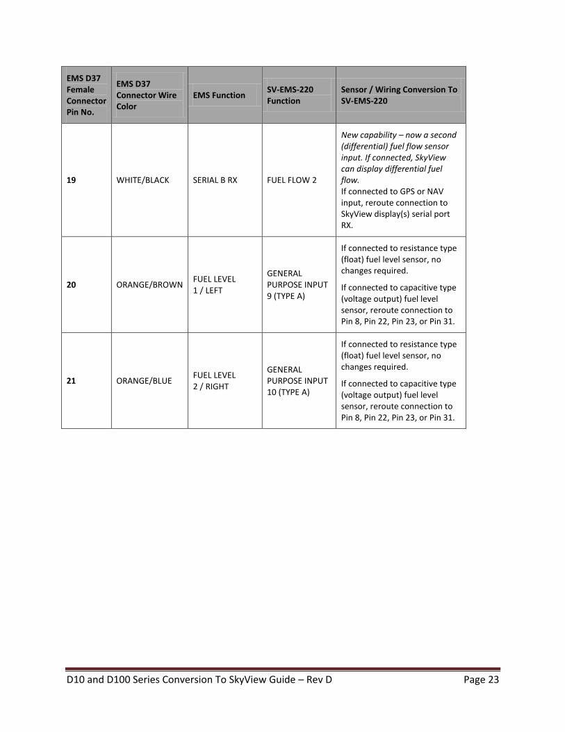
19 WHITE/BLACK SERIAL B RX FUEL FLOW 2
New capability – now a second (differential) fuel flow sensor input. If connected, SkyView can display differential fuel flow. If connected to GPS or NAV input, reroute connection to SkyView display(s) serial port RX.
20 ORANGE/BROWN FUEL LEVEL 1 / LEFT
GENERAL PURPOSE INPUT 9 (TYPE A)
If connected to resistance type (float) fuel level sensor, no changes required.
If connected to capacitive type (voltage output) fuel level sensor, reroute connection to Pin 8, Pin 22, Pin 23, or Pin 31.
21 ORANGE/BLUE FUEL LEVEL 2 / RIGHT
GENERAL PURPOSE INPUT 10 (TYPE A)
If connected to resistance type (float) fuel level sensor, no changes required.
If connected to capacitive type (voltage output) fuel level sensor, reroute connection to Pin 8, Pin 22, Pin 23, or Pin 31.
D10 and D100 Series Conversion To SkyView Guide – Rev D Page 24
EMS D37 Female Connector Pin No.
EMS D37 Connector Wire Color
EMS Function SV-EMS-220 Function
Sensor / Wiring Conversion To SV-EMS-220
22 VIOLET/YELLOW GENERAL PURPOSE INPUT 2
GENERAL PURPOSE INPUT 2 (TYPE C)
If connected to Dynon P/N 100413-000 Carb Temp Sensor, remove the 1K resistor installed between this pin and Pin 18 (+5V Output).
If connected to Dynon 100411-000 Pressure Sensor for monitoring coolant, remove the 1K resistor installed between this pin and Pin 18 (+5V Output).
If connected to Dynon 100409-000 or 100409-001 Oil / Coolant Temp Sensor for monitoring coolant, remove the 1K resistor installed between this pin and Pin 18 (+5V Output).
If connected to Rotax CHT, remove the 1.21K resistor between this pin and Pin 18 (+5V Output).
If connected to Dynon 100433-000 OAT, see Guidelines For Connection of Installed OAT to SV-ADAHRS-200/201 OAT Input.
D10 and D100 Series Conversion To SkyView Guide – Rev D Page 25
EMS D37 Female Connector Pin No.
EMS D37 Connector Wire Color
EMS Function SV-EMS-220 Function
Sensor / Wiring Conversion To SV-EMS-220
23 VIOLET/GREEN GENERAL PURPOSE INPUT 3
GENERAL PURPOSE INPUT 3 (TYPE C)
New capability; can now accept voltage input similar to Pins 8, 22, and 31 (Enhanced General Purpose Inputs 4, 2, and 13 respectively). If connected to Dynon P/N 100413-000 Carb Temp Sensor, remove the 1K resistor installed between this pin and Pin 18 (+5V Output).
If connected to Dynon 100411-000 Pressure Sensor for monitoring coolant, remove the 1K resistor installed between this pin and Pin 18 (+5V Output).
If connected to Dynon 100409-000 or 100409-001 Oil / Coolant Temp Sensor for monitoring coolant, remove the 1K resistor installed between this pin and Pin 18 (+5V Output).
If connected to Rotax CHT, remove the 1.21K resistor between this pin and Pin 18 (+5V Output).
If connected to Dynon 100433-000 OAT, see Guidelines For Connection of Installed OAT to SV-ADAHRS-200/201 OAT Input.
24 ORANGE/GREEN AMPS TRANSDUCER +
AMPS TRANSDUCER +
If connected to Dynon 100412-000: no changes required.
If connected to GRT-CS-01: Green (output) wire must be moved to Pin 8 or Pin 22 or Pin 31 – see SkyView System Installation Guide
25 ORANGE/VIOLET AMPS TRANSDUCER -
AMPS TRANSDUCER -
No changes required.
D10 and D100 Series Conversion To SkyView Guide – Rev D Page 26
EMS D37 Female Connector Pin No.
EMS D37 Connector Wire Color
EMS Function SV-EMS-220 Function
Sensor / Wiring Conversion To SV-EMS-220
26 GREEN/RED MANIFOLD PRESSURE
MANIFOLD PRESSURE
No changes required.
27 (NO WIRE)
GENERAL PURPOSE THERMOCOUPLE + (J OR K)
GENERAL PURPOSE THERMOCOUPLE 1 + (J OR K)
No changes required.
28 (NO WIRE)
GENERAL PURPOSE THERMOCOUPLE - (J OR K)
GENERAL PURPOSE THERMOCOUPLE 1 + (J OR K)
No changes required.
29 YELLOW/GREEN EMS ALARM LIGHT OUTPUT
EMS ALARM LIGHT OUTPUT
No changes required.
30 BLACK PC SERIAL GROUND
GROUND
New capability - now a sensor ground. Cut off the 9-pin connector to use this wire. If connected to PC (firmware, data logs), no longer required.
31 WHITE/ORANGE AUDIO OUTPUT GENERAL PURPOSE INPUT 13 (TYPE C)
New capability – now a General Purpose input. If connected to audio output, reroute this wire to SkyView display. Because EFIS Audio was mono, connect this wire to both SkyView Display PIN 13 – AUDIO OUTPUT LEFT and PIN 31 – AUDIO OUTPUT RIGHT If a 10K potentiometer was installed on this to adjust volume, remove it (SkyView has internal volume adjustment).
32 WHITE/GREEN RPM LEFT STANDARD VOLTAGE RPM LEFT
If connected to Rotax engine (5
th trigger coil), remove 30K
resistor.
If not connected to Rotax, no changes required.
D10 and D100 Series Conversion To SkyView Guide – Rev D Page 27
EMS D37 Female Connector Pin No.
EMS D37 Connector Wire Color
EMS Function SV-EMS-220 Function
Sensor / Wiring Conversion To SV-EMS-220
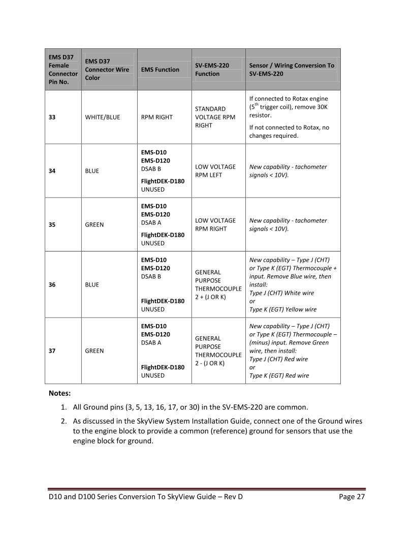
33 WHITE/BLUE RPM RIGHT STANDARD VOLTAGE RPM RIGHT
If connected to Rotax engine (5
th trigger coil), remove 30K
resistor.
If not connected to Rotax, no changes required.
34 BLUE
EMS-D10 EMS-D120 DSAB B
FlightDEK-D180 UNUSED
LOW VOLTAGE RPM LEFT
New capability - tachometer signals < 10V).
35 GREEN
EMS-D10 EMS-D120 DSAB A
FlightDEK-D180 UNUSED
LOW VOLTAGE RPM RIGHT
New capability - tachometer signals < 10V).
36 BLUE
EMS-D10 EMS-D120 DSAB B
FlightDEK-D180 UNUSED
GENERAL PURPOSE THERMOCOUPLE 2 + (J OR K)
New capability – Type J (CHT) or Type K (EGT) Thermocouple + input. Remove Blue wire, then install: Type J (CHT) White wire or Type K (EGT) Yellow wire
37 GREEN
EMS-D10 EMS-D120 DSAB A
FlightDEK-D180 UNUSED
GENERAL PURPOSE THERMOCOUPLE 2 - (J OR K)
New capability – Type J (CHT) or Type K (EGT) Thermocouple – (minus) input. Remove Green wire, then install: Type J (CHT) Red wire or Type K (EGT) Red wire
Notes:
1. All Ground pins (3, 5, 13, 16, 17, or 30) in the SV-EMS-220 are common.
2. As discussed in the SkyView System Installation Guide, connect one of the Ground wires to the engine block to provide a common (reference) ground for sensors that use the engine block for ground.

D10 and D100 Series Conversion To SkyView Guide – Rev D Page 28
D10 and D100 Series Conversion To SkyView Guide – Rev D Page 29
Guidelines for Conversion of Dynon Avionics EMS CHT/EGT Harness to SkyView SV-EMS-220 CHT/EGT Harness
The CHT/EGT 25-pin connector is “Plug and Play”. If the CHTs and EGTs were installed and working on the Dynon Avionics EMS and no changes are needed, there is no wiring conversion required to work with an SV-EMS-220. The CHT/EGT 25-pin female connector on the SV-EMS-220 is electrically compatible with the CHT/EGT 25-pin female connector on a Dynon Avionics EMS.
For a detailed explanation of the full (enhanced) range of capabilities for each pin of the SV-EMS-220 CHT/EGT 25-pin connector, see these tables and figures in the SkyView System Installation Guide, SV-EMS-220 Installation and Configuration:
SV-EMS-220 Female D25 Pin-to-Sensor Compatibility
Thermocouple Wire Harness Male D25 Pin Insertion View (Rear)
D10 and D100 Series Conversion To SkyView Guide – Rev D Page 30
EMS Sensor Type Conversion to SkyView Sensor Type
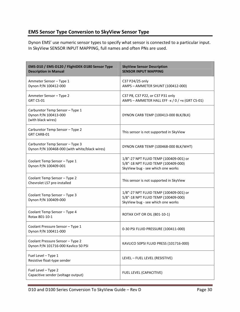
Dynon EMS’ use numeric sensor types to specify what sensor is connected to a particular input. In SkyView SENSOR INPUT MAPPING, full names and often PNs are used.
EMS-D10 / EMS-D120 / FlightDEK-D180 Sensor Type Description in Manual
SkyView Sensor Description SENSOR INPUT MAPPING
Ammeter Sensor – Type 1 Dynon P/N 100412-000
C37 P24/25 only AMPS – AMMETER SHUNT (100412-000)
Ammeter Sensor – Type 2 GRT CS-01
C37 P8, C37 P22, or C37 P31 only AMPS – AMMETER HALL EFF -x / 0 / +x (GRT CS-01)
Carburetor Temp Sensor – Type 1 Dynon P/N 100413-000 (with black wires)
DYNON CARB TEMP (100413-000 BLK/BLK)
Carburetor Temp Sensor – Type 2 GRT CARB-01
This sensor is not supported in SkyView
Carburetor Temp Sensor – Type 3 Dynon P/N 100468-000 (with white/black wires)
DYNON CARB TEMP (100468-000 BLK/WHT)
Coolant Temp Sensor – Type 1 Dynon P/N 100409-001
1/8”-27 NPT FLUID TEMP (100409-001) or 5/8”-18 NPT FLUID TEMP (100409-000) SkyView bug - see which one works
Coolant Temp Sensor – Type 2 Chevrolet LS7 pre-installed
This sensor is not supported in SkyView
Coolant Temp Sensor – Type 3 Dynon P/N 100409-000
1/8”-27 NPT FLUID TEMP (100409-001) or 5/8”-18 NPT FLUID TEMP (100409-000) SkyView bug - see which one works
Coolant Temp Sensor – Type 4 Rotax 801-10-1
ROTAX CHT OR OIL (801-10-1)
Coolant Pressure Sensor – Type 1 Dynon P/N 100411-000
0-30 PSI FLUID PRESSURE (100411-000)
Coolant Pressure Sensor – Type 2 Dynon P/N 101716-000 Kavlico 50 PSI
KAVLICO 50PSI FLUID PRESS (101716-000)
Fuel Level – Type 1 Resistive float-type sender
LEVEL – FUEL LEVEL (RESISTIVE)
Fuel Level – Type 2 Capacitive sender (voltage output)
FUEL LEVEL (CAPACITIVE)

D10 and D100 Series Conversion To SkyView Guide – Rev D Page 31
EMS-D10 / EMS-D120 / FlightDEK-D180 Sensor Type Description in Manual
SkyView Sensor Description SENSOR INPUT MAPPING
Fuel Pressure Sensor – Type 1 Dynon P/N 100411-000 (Legacy 0-30 PSI carbureted)
0-30 PSI FLUID PRESSURE (100411-000)
Fuel Pressure Sensor – Type 2 Dynon P/N 100411-001 (Legacy 0-80 PSI injected)
0-80 PSI FLUID PRESSURE (100411-001)
Fuel Pressure Sensor – Type 3 GRT LPS-02 (remove the external pull-up resistor)
This sensor is not supported in SkyView
Fuel Pressure Sensor – Type 4 Stewart Warner 82504-F
STEWART WARNER 15PSI (82504-F)
Fuel Pressure Sensor – Type 5 Dynon P/N 101715-000 Kavlico 5 PSI Gravity Feed
KAVLICO 5PSI FLUID PRESS (101715-000)
Fuel Pressure Sensor – Type 6 Dynon P/N 101690-000 Kavlico 15 PSI Gravity Feed
KAVLICO 15PSI FLUID PRESS (101690-000)
Fuel Pressure Sensor – Type 7 Dynon P/N 101716-000 Kavlico 50 PSI Gravity Feed
KAVLICO 50PSI FLUID PRESS (101716-000)
GP Temp Sensor – Type 1 Dynon P/N 100433-000 (2-wire) Dynon P/N 100433-001 (3-wire)
DYNON 2-WIRE OAT (100433-00X)
GP Temp Sensor – Type 2 GRT OAT-01
This sensor is not supported in SkyView
Manifold Pressure – Type 1 Dynon P/N 100434-000
(C37 P26 only) PRESSURE – 100434-000
Manifold Pressure – Type 2 (GRT MAP-01 or MAP-02)
This sensor is not supported in SkyView
OAT Sensor – Type 1 Dynon P/N 100433-000 (2-wire) Dynon P/N 100433-001 (3-wire)
DYNON 2-WIRE OAT (100433-00X)
OAT Sensor – Type 2 GRT OAT-01
This sensor is not supported in SkyView
D10 and D100 Series Conversion To SkyView Guide – Rev D Page 32
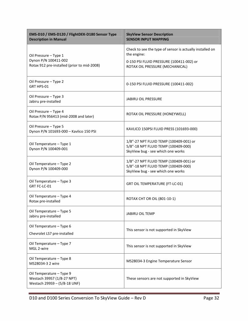
EMS-D10 / EMS-D120 / FlightDEK-D180 Sensor Type Description in Manual
SkyView Sensor Description SENSOR INPUT MAPPING
Oil Pressure – Type 1 Dynon P/N 100411-002 Rotax 912 pre-installed (prior to mid-2008)
Check to see the type of sensor is actually installed on the engine:
0-150 PSI FLUID PRESSURE (100411-002) or ROTAX OIL PRESSURE (MECHANICAL)
Oil Pressure – Type 2 GRT HPS-01
0-150 PSI FLUID PRESSURE (100411-002)
Oil Pressure – Type 3 Jabiru pre-installed
JABIRU OIL PRESSURE
Oil Pressure – Type 4 Rotax P/N 956413 (mid-2008 and later)
ROTAX OIL PRESSURE (HONEYWELL)
Oil Pressure – Type 5 Dynon P/N 101693-000 – Kavlico 150 PSI
KAVLICO 150PSI FLUID PRESS (101693-000)
Oil Temperature – Type 1 Dynon P/N 100409-001
1/8”-27 NPT FLUID TEMP (100409-001) or 5/8”-18 NPT FLUID TEMP (100409-000) SkyView bug - see which one works
Oil Temperature – Type 2 Dynon P/N 100409-000
1/8”-27 NPT FLUID TEMP (100409-001) or 5/8”-18 NPT FLUID TEMP (100409-000) SkyView bug - see which one works
Oil Temperature – Type 3 GRT FC-LC-01
GRT OIL TEMPERATURE (FT-LC-01)
Oil Temperature – Type 4 Rotax pre-installed
ROTAX CHT OR OIL (801-10-1)
Oil Temperature – Type 5 Jabiru pre-installed
JABIRU OIL TEMP
Oil Temperature – Type 6
Chevrolet LS7 pre-installed This sensor is not supported in SkyView
Oil Temperature – Type 7 MGL 2-wire
This sensor is not supported in SkyView
Oil Temperature – Type 8 MS28034-3 2 wire
MS28034-3 Engine Temperature Sensor
Oil Temperature – Type 9 Westach 399S7 (1/8-27 NPT) Westach 299S9 – (5/8-18 UNF)
These sensors are not supported in SkyView
D10 and D100 Series Conversion To SkyView Guide – Rev D Page 33
EMS-D10 / EMS-D120 / FlightDEK-D180 Sensor Type Description in Manual
SkyView Sensor Description SENSOR INPUT MAPPING
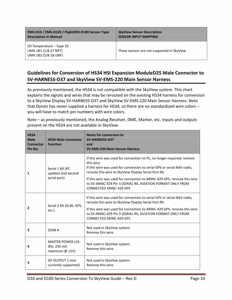
Oil Temperature – Type 10 UMA 1B1 (1/8-27 NPT) UMA 1B3 (5/8-18 UNF)
These sensors are not supported in SkyView
Guidelines for Conversion of HS34 HSI Expansion ModuleD25 Male Connector to SV-HARNESS-D37 and SkyView SV-EMS-220 Main Sensor Harness
As previously mentioned, the HS34 is not compatible with the SkyView system. This chart explains the signals and wires that may be rerouted on the existing HS34 harness for conversion to a SkyView Display SV-HARNESS-D37 and SkyView SV-EMS-220 Main Sensor Harness. Note that Dynon has never supplied a harness for HS34, so there are no standardized wire colors – you will have to match pin numbers with wire colors.
Note – as previously mentioned, the Analog Resolver, DME, Marker, etc. inputs and outputs present on the HS34 are not available in SkyView.
HS34 Male Connector Pin No.
HS34 Male Connector Function
Notes for conversion to SV-HARNESS-D37 and SV-EMS-220 Main Sensor Harness
1 Serial 1 RX (PC updates and second serial port)
If this wire was used for connection to PC, no longer required; remove this wire. If this wire was used for connection to serial GPS or serial NAV radio, reroute this wire to SkyView Display Serial Port RX.
If this wire was used for connection to ARINC-429 GPS, reroute this wire to SV-ARINC-429 Pin 3 (SERIAL RX, AVIATION FORMAT ONLY FROM CONNECTED ARINC-429 GPS
2 Serial 2 RX (SL30, GPS, etc.)
If this wire was used for connection to serial GPS or serial NAV radio, reroute this wire to SkyView Display Serial Port RX.
If this wire was used for connection to ARINC-429 GPS, reroute this wire to SV-ARINC-429 Pin 3 (SERIAL RX, AVIATION FORMAT ONLY FROM CONNECTED ARINC-429 GPS
3 DSAB A Not used in SkyView system. Remove this wire.
4 MASTER POWER (10-30v, 250 mA maximum @ 12V)
Not used in SkyView system. Remove this wire.
5 GP OUTPUT 1 (not currently supported)
Not used in SkyView system. Remove this wire.

D10 and D100 Series Conversion To SkyView Guide – Rev D Page 34
HS34 Male Connector Pin No.
HS34 Male Connector Function
Notes for conversion to SV-HARNESS-D37 and SV-EMS-220 Main Sensor Harness
6 GP OUTPUT 2 (not currently supported)
Not used in SkyView system. Remove this wire.
7 GP 1 in (Same as EMS GP in)
Reroute this wire to an available General Purpose Input Pin on SV-EMS-220 Main Sensor Harness: Pin 4 Violet/Blue GENERAL PURPOSE INPUT 1 (TYPE A) Pin 6 White/Yellow GENERAL PURPOSE INPUT 11 (TYPE B) Pin 7 White/Brown GENERAL PURPOSE INPUT 12 (TYPE A) Pin 8 Brown ENHANCED GENERAL PURPOSE INPUT 4 (TYPE C) Pin 9 Brown/Blue GENERAL PURPOSE INPUT 5 (TYPE A) Pin 10 Brown/Yellow GENERAL PURPOSE INPUT 6 (TYPE A) Pin 11 Orange GENERAL PURPOSE INPUT 7 (TYPE A) Pin 12 Yellow GENERAL PURPOSE INPUT 8 (TYPE A) Pin 20 Orange/Brown GENERAL PURPOSE INPUT 9 (TYPE A) Pin 21 Orange/Blue GENERAL PURPOSE INPUT 10 (TYPE A) Pin 22 Violet/Yellow ENHANCED GENERAL PURPOSE INPUT 2 (TYPE C) Pin 23 Violet/Green GENERAL PURPOSE INPUT 3 (TYPE C) Pin 31 White/Orange ENHANCED GENERAL PURPOSE INPUT 13 (TYPE C) If this wire was used for Dynon P/N 100413-000 Carb Temp Sensor, remove the 1K resistor installed between this pin and Pin 9 (+5V OUT).
If this wire was used for Dynon 100411-000 Pressure Sensor for monitoring coolant, remove the 1K resistor installed between this pin and Pin 9 (+5V OUT).
If this wire was used for Dynon 100409-000 or 100409-001 Oil / Coolant Temp Sensor for monitoring coolant, remove the 1K resistor installed between this pin and Pin 9 (+5V OUT).
If this wire was used for Rotax CHT, remove the 1.21K resistor between this pin and Pin 9 (+5V OUT).
If this wire was used for Dynon 100433-000 OAT, see Guidelines For Connection of Installed OAT to SV-ADAHRS-200/201 OAT Input.

D10 and D100 Series Conversion To SkyView Guide – Rev D Page 35
HS34 Male Connector Pin No.
HS34 Male Connector Function
Notes for conversion to SV-HARNESS-D37 and SV-EMS-220 Main Sensor Harness
8 GP 2 in (Same as EMS GP in)
Reroute this wire to an available General Purpose Input Pin on SV-EMS-220 Main Sensor Harness: Pin 4 Violet/Blue GENERAL PURPOSE INPUT 1 (TYPE A) Pin 6 White/Yellow GENERAL PURPOSE INPUT 11 (TYPE B) Pin 7 White/Brown GENERAL PURPOSE INPUT 12 (TYPE A) Pin 8 Brown ENHANCED GENERAL PURPOSE INPUT 4 (TYPE C) Pin 9 Brown/Blue GENERAL PURPOSE INPUT 5 (TYPE A) Pin 10 Brown/Yellow GENERAL PURPOSE INPUT 6 (TYPE A) Pin 11 Orange GENERAL PURPOSE INPUT 7 (TYPE A) Pin 12 Yellow GENERAL PURPOSE INPUT 8 (TYPE A) Pin 20 Orange/Brown GENERAL PURPOSE INPUT 9 (TYPE A) Pin 21 Orange/Blue GENERAL PURPOSE INPUT 10 (TYPE A) Pin 22 Violet/Yellow ENHANCED GENERAL PURPOSE INPUT 2 (TYPE C) Pin 23 Violet/Green GENERAL PURPOSE INPUT 3 (TYPE C) Pin 31 White/Orange ENHANCED GENERAL PURPOSE INPUT 13 (TYPE C) If this wire was used for Dynon P/N 100413-000 Carb Temp Sensor, remove the 1K resistor installed between this pin and Pin 9 (+5V OUT).
If this wire was used for Dynon 100411-000 Pressure Sensor for monitoring coolant, remove the 1K resistor installed between this pin and Pin 9 (+5V OUT).
If this wire was used for Dynon 100409-000 or 100409-001 Oil / Coolant Temp Sensor for monitoring coolant, remove the 1K resistor installed between this pin and Pin 9 (+5V OUT).
If this wire was used for Rotax CHT, remove the 1.21K resistor between this pin and Pin 9 (+5V OUT).
If this wire was used for Dynon 100433-000 OAT, see Guidelines For Connection of Installed OAT to SV-ADAHRS-200/201 OAT Input.
9 +5V OUT Remove any resistors connected between this pin and other pins (pull-ups), esp. Pin 7, Pin 8, Pin 13 (GP Inputs – see notes on those pins.)
10 GP 6 IN (+15V GP In, not currently supported)
Not used in SkyView system. Remove this wire.
11 GP 5 IN (+15V GP In, not currently supported)
Not used in SkyView system. Remove this wire.
12 GP 4 IN (+15V GP In, not currently supported)
Not used in SkyView system. Remove this wire.
D10 and D100 Series Conversion To SkyView Guide – Rev D Page 36
HS34 Male Connector Pin No.
HS34 Male Connector Function
Notes for conversion to SV-HARNESS-D37 and SV-EMS-220 Main Sensor Harness
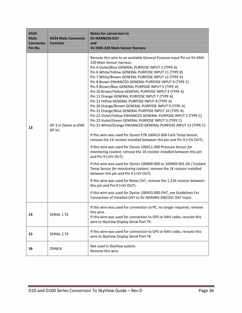
13 GP 3 in (Same as EMS GP in)
Reroute this wire to an available General Purpose Input Pin on SV-EMS-220 Main Sensor Harness: Pin 4 Violet/Blue GENERAL PURPOSE INPUT 1 (TYPE A) Pin 6 White/Yellow GENERAL PURPOSE INPUT 11 (TYPE B) Pin 7 White/Brown GENERAL PURPOSE INPUT 12 (TYPE A) Pin 8 Brown ENHANCED GENERAL PURPOSE INPUT 4 (TYPE C) Pin 9 Brown/Blue GENERAL PURPOSE INPUT 5 (TYPE A) Pin 10 Brown/Yellow GENERAL PURPOSE INPUT 6 (TYPE A) Pin 11 Orange GENERAL PURPOSE INPUT 7 (TYPE A) Pin 12 Yellow GENERAL PURPOSE INPUT 8 (TYPE A) Pin 20 Orange/Brown GENERAL PURPOSE INPUT 9 (TYPE A) Pin 21 Orange/Blue GENERAL PURPOSE INPUT 10 (TYPE A) Pin 22 Violet/Yellow ENHANCED GENERAL PURPOSE INPUT 2 (TYPE C) Pin 23 Violet/Green GENERAL PURPOSE INPUT 3 (TYPE C) Pin 31 White/Orange ENHANCED GENERAL PURPOSE INPUT 13 (TYPE C) If this wire was used for Dynon P/N 100413-000 Carb Temp Sensor, remove the 1K resistor installed between this pin and Pin 9 (+5V OUT).
If this wire was used for Dynon 100411-000 Pressure Sensor for monitoring coolant, remove the 1K resistor installed between this pin and Pin 9 (+5V OUT).
If this wire was used for Dynon 100409-000 or 100409-001 Oil / Coolant Temp Sensor for monitoring coolant, remove the 1K resistor installed between this pin and Pin 9 (+5V OUT).
If this wire was used for Rotax CHT, remove the 1.21K resistor between this pin and Pin 9 (+5V OUT).
If this wire was used for Dynon 100433-000 OAT, see Guidelines For Connection of Installed OAT to SV-ADAHRS-200/201 OAT Input.
14 SERIAL 1 TX
If this wire was used for connection to PC, no longer required; remove this wire. If this wire was used for connection to GPS or NAV radio, reroute this wire to SkyView Display Serial Port TX.
15 SERIAL 2 TX If this wire was used for connection to GPS or NAV radio, reroute this wire to SkyView Display Serial Port TX.
16 DSAB B Not used in SkyView system. Remove this wire.
D10 and D100 Series Conversion To SkyView Guide – Rev D Page 37
HS34 Male Connector Pin No.
HS34 Male Connector Function
Notes for conversion to SV-HARNESS-D37 and SV-EMS-220 Main Sensor Harness
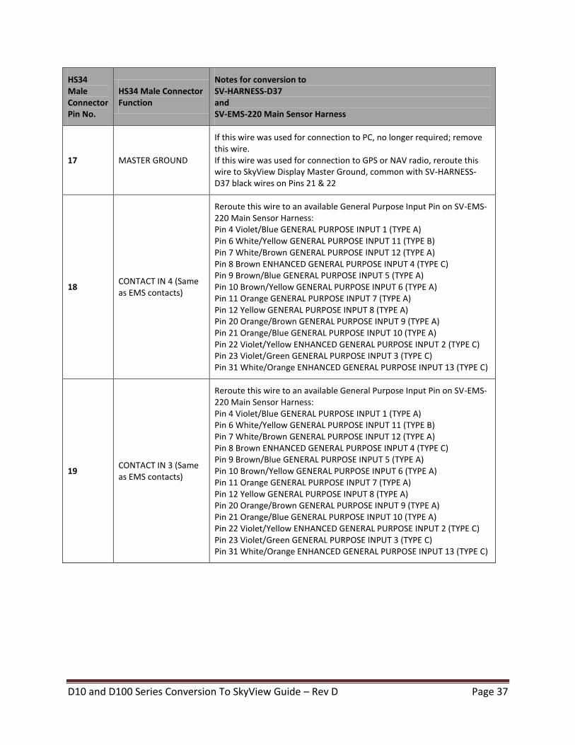
17 MASTER GROUND
If this wire was used for connection to PC, no longer required; remove this wire. If this wire was used for connection to GPS or NAV radio, reroute this wire to SkyView Display Master Ground, common with SV-HARNESS-D37 black wires on Pins 21 & 22
18 CONTACT IN 4 (Same as EMS contacts)
Reroute this wire to an available General Purpose Input Pin on SV-EMS-220 Main Sensor Harness: Pin 4 Violet/Blue GENERAL PURPOSE INPUT 1 (TYPE A) Pin 6 White/Yellow GENERAL PURPOSE INPUT 11 (TYPE B) Pin 7 White/Brown GENERAL PURPOSE INPUT 12 (TYPE A) Pin 8 Brown ENHANCED GENERAL PURPOSE INPUT 4 (TYPE C) Pin 9 Brown/Blue GENERAL PURPOSE INPUT 5 (TYPE A) Pin 10 Brown/Yellow GENERAL PURPOSE INPUT 6 (TYPE A) Pin 11 Orange GENERAL PURPOSE INPUT 7 (TYPE A) Pin 12 Yellow GENERAL PURPOSE INPUT 8 (TYPE A) Pin 20 Orange/Brown GENERAL PURPOSE INPUT 9 (TYPE A) Pin 21 Orange/Blue GENERAL PURPOSE INPUT 10 (TYPE A) Pin 22 Violet/Yellow ENHANCED GENERAL PURPOSE INPUT 2 (TYPE C) Pin 23 Violet/Green GENERAL PURPOSE INPUT 3 (TYPE C) Pin 31 White/Orange ENHANCED GENERAL PURPOSE INPUT 13 (TYPE C)
19 CONTACT IN 3 (Same as EMS contacts)
Reroute this wire to an available General Purpose Input Pin on SV-EMS-220 Main Sensor Harness: Pin 4 Violet/Blue GENERAL PURPOSE INPUT 1 (TYPE A) Pin 6 White/Yellow GENERAL PURPOSE INPUT 11 (TYPE B) Pin 7 White/Brown GENERAL PURPOSE INPUT 12 (TYPE A) Pin 8 Brown ENHANCED GENERAL PURPOSE INPUT 4 (TYPE C) Pin 9 Brown/Blue GENERAL PURPOSE INPUT 5 (TYPE A) Pin 10 Brown/Yellow GENERAL PURPOSE INPUT 6 (TYPE A) Pin 11 Orange GENERAL PURPOSE INPUT 7 (TYPE A) Pin 12 Yellow GENERAL PURPOSE INPUT 8 (TYPE A) Pin 20 Orange/Brown GENERAL PURPOSE INPUT 9 (TYPE A) Pin 21 Orange/Blue GENERAL PURPOSE INPUT 10 (TYPE A) Pin 22 Violet/Yellow ENHANCED GENERAL PURPOSE INPUT 2 (TYPE C) Pin 23 Violet/Green GENERAL PURPOSE INPUT 3 (TYPE C) Pin 31 White/Orange ENHANCED GENERAL PURPOSE INPUT 13 (TYPE C)
D10 and D100 Series Conversion To SkyView Guide – Rev D Page 38
HS34 Male Connector Pin No.
HS34 Male Connector Function
Notes for conversion to SV-HARNESS-D37 and SV-EMS-220 Main Sensor Harness
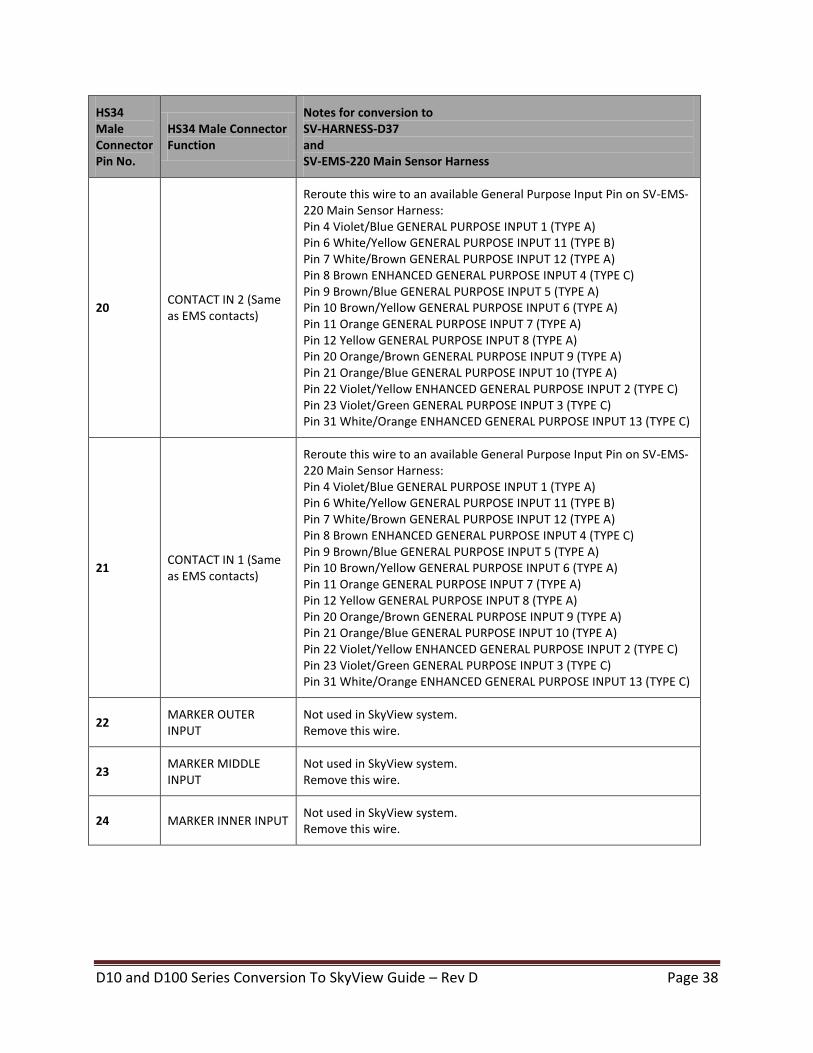
20 CONTACT IN 2 (Same as EMS contacts)
Reroute this wire to an available General Purpose Input Pin on SV-EMS-220 Main Sensor Harness: Pin 4 Violet/Blue GENERAL PURPOSE INPUT 1 (TYPE A) Pin 6 White/Yellow GENERAL PURPOSE INPUT 11 (TYPE B) Pin 7 White/Brown GENERAL PURPOSE INPUT 12 (TYPE A) Pin 8 Brown ENHANCED GENERAL PURPOSE INPUT 4 (TYPE C) Pin 9 Brown/Blue GENERAL PURPOSE INPUT 5 (TYPE A) Pin 10 Brown/Yellow GENERAL PURPOSE INPUT 6 (TYPE A) Pin 11 Orange GENERAL PURPOSE INPUT 7 (TYPE A) Pin 12 Yellow GENERAL PURPOSE INPUT 8 (TYPE A) Pin 20 Orange/Brown GENERAL PURPOSE INPUT 9 (TYPE A) Pin 21 Orange/Blue GENERAL PURPOSE INPUT 10 (TYPE A) Pin 22 Violet/Yellow ENHANCED GENERAL PURPOSE INPUT 2 (TYPE C) Pin 23 Violet/Green GENERAL PURPOSE INPUT 3 (TYPE C) Pin 31 White/Orange ENHANCED GENERAL PURPOSE INPUT 13 (TYPE C)
21 CONTACT IN 1 (Same as EMS contacts)
Reroute this wire to an available General Purpose Input Pin on SV-EMS-220 Main Sensor Harness: Pin 4 Violet/Blue GENERAL PURPOSE INPUT 1 (TYPE A) Pin 6 White/Yellow GENERAL PURPOSE INPUT 11 (TYPE B) Pin 7 White/Brown GENERAL PURPOSE INPUT 12 (TYPE A) Pin 8 Brown ENHANCED GENERAL PURPOSE INPUT 4 (TYPE C) Pin 9 Brown/Blue GENERAL PURPOSE INPUT 5 (TYPE A) Pin 10 Brown/Yellow GENERAL PURPOSE INPUT 6 (TYPE A) Pin 11 Orange GENERAL PURPOSE INPUT 7 (TYPE A) Pin 12 Yellow GENERAL PURPOSE INPUT 8 (TYPE A) Pin 20 Orange/Brown GENERAL PURPOSE INPUT 9 (TYPE A) Pin 21 Orange/Blue GENERAL PURPOSE INPUT 10 (TYPE A) Pin 22 Violet/Yellow ENHANCED GENERAL PURPOSE INPUT 2 (TYPE C) Pin 23 Violet/Green GENERAL PURPOSE INPUT 3 (TYPE C) Pin 31 White/Orange ENHANCED GENERAL PURPOSE INPUT 13 (TYPE C)
22 MARKER OUTER INPUT
Not used in SkyView system. Remove this wire.
23 MARKER MIDDLE INPUT
Not used in SkyView system. Remove this wire.
24 MARKER INNER INPUT Not used in SkyView system. Remove this wire.
D10 and D100 Series Conversion To SkyView Guide – Rev D Page 39
HS34 Male Connector Pin No.
HS34 Male Connector Function
Notes for conversion to SV-HARNESS-D37 and SV-EMS-220 Main Sensor Harness
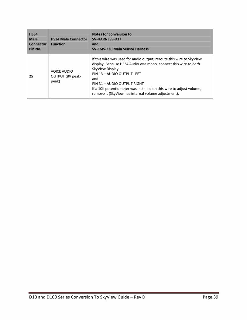
25 VOICE AUDIO OUTPUT (8V peak-peak)
If this wire was used for audio output, reroute this wire to SkyView display. Because HS34 Audio was mono, connect this wire to both SkyView Display PIN 13 – AUDIO OUTPUT LEFT and PIN 31 – AUDIO OUTPUT RIGHT If a 10K potentiometer was installed on this wire to adjust volume, remove it (SkyView has internal volume adjustment).
D10 and D100 Series Conversion To SkyView Guide – Rev D Page 40
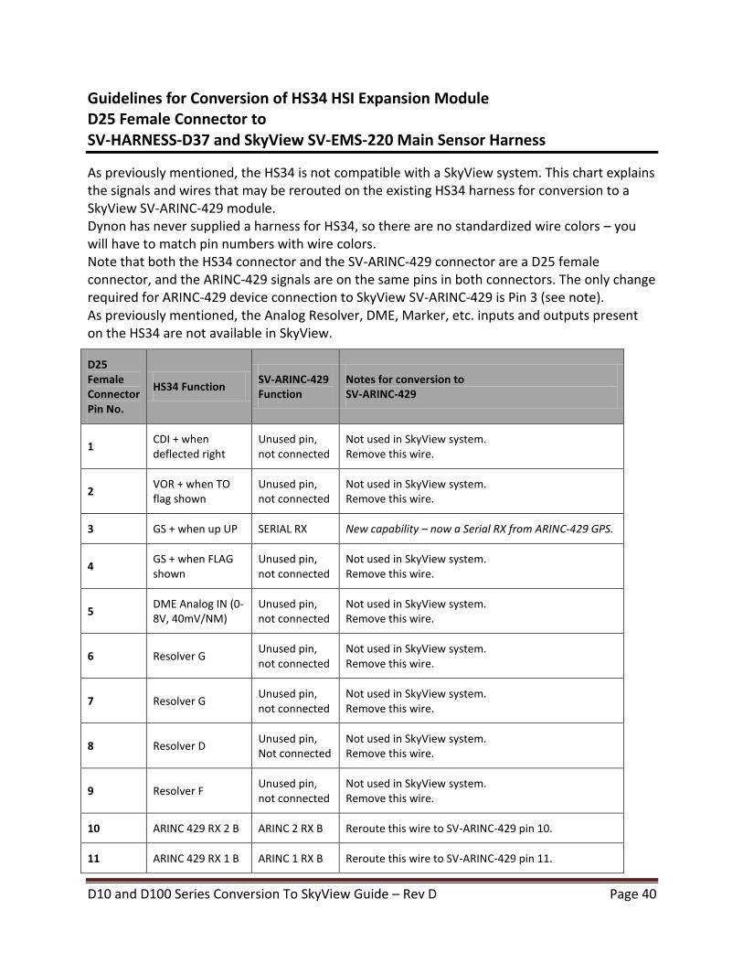
Guidelines for Conversion of HS34 HSI Expansion Module D25 Female Connector to SV-HARNESS-D37 and SkyView SV-EMS-220 Main Sensor Harness
As previously mentioned, the HS34 is not compatible with a SkyView system. This chart explains the signals and wires that may be rerouted on the existing HS34 harness for conversion to a SkyView SV-ARINC-429 module. Dynon has never supplied a harness for HS34, so there are no standardized wire colors – you will have to match pin numbers with wire colors. Note that both the HS34 connector and the SV-ARINC-429 connector are a D25 female connector, and the ARINC-429 signals are on the same pins in both connectors. The only change required for ARINC-429 device connection to SkyView SV-ARINC-429 is Pin 3 (see note). As previously mentioned, the Analog Resolver, DME, Marker, etc. inputs and outputs present on the HS34 are not available in SkyView.
D25 Female Connector Pin No.
HS34 Function SV-ARINC-429 Function
Notes for conversion to SV-ARINC-429
1 CDI + when deflected right
Unused pin, not connected
Not used in SkyView system. Remove this wire.
2 VOR + when TO flag shown
Unused pin, not connected
Not used in SkyView system. Remove this wire.
3 GS + when up UP SERIAL RX New capability – now a Serial RX from ARINC-429 GPS.
4 GS + when FLAG shown
Unused pin, not connected
Not used in SkyView system. Remove this wire.
5 DME Analog IN (0-8V, 40mV/NM)
Unused pin, not connected
Not used in SkyView system. Remove this wire.
6 Resolver G Unused pin, not connected
Not used in SkyView system. Remove this wire.
7 Resolver G Unused pin, not connected
Not used in SkyView system. Remove this wire.
8 Resolver D Unused pin, Not connected
Not used in SkyView system. Remove this wire.
9 Resolver F Unused pin, not connected
Not used in SkyView system. Remove this wire.
10 ARINC 429 RX 2 B ARINC 2 RX B Reroute this wire to SV-ARINC-429 pin 10.
11 ARINC 429 RX 1 B ARINC 1 RX B Reroute this wire to SV-ARINC-429 pin 11.
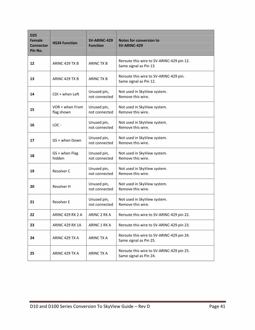
D10 and D100 Series Conversion To SkyView Guide – Rev D Page 41
D25 Female Connector Pin No.
HS34 Function SV-ARINC-429 Function
Notes for conversion to SV-ARINC-429
12 ARINC 429 TX B ARINC TX B Reroute this wire to SV-ARINC-429 pin 12. Same signal as Pin 13
13 ARINC 429 TX B ARINC TX B Reroute this wire to SV-ARINC-429 pin. Same signal as Pin 12.
14 CDI + when Left Unused pin, not connected
Not used in SkyView system. Remove this wire.
15 VOR + when From flag shown
Unused pin, not connected
Not used in SkyView system. Remove this wire.
16 LOC - Unused pin, not connected
Not used in SkyView system. Remove this wire.
17 GS + when Down Unused pin, not connected
Not used in SkyView system. Remove this wire.
18 GS + when Flag hidden
Unused pin, not connected
Not used in SkyView system. Remove this wire.
19 Resolver C Unused pin, not connected
Not used in SkyView system. Remove this wire.
20 Resolver H Unused pin, not connected
Not used in SkyView system. Remove this wire.
21 Resolver E Unused pin, not connected
Not used in SkyView system. Remove this wire.
22 ARINC 429 RX 2 A ARINC 2 RX A Reroute this wire to SV-ARINC-429 pin 22.
23 ARINC 429 RX 1A ARINC 1 RX A Reroute this wire to SV-ARINC-429 pin 23.
24 ARINC 429 TX A ARINC TX A Reroute this wire to SV-ARINC-429 pin 24. Same signal as Pin 25.
25 ARINC 429 TX A ARINC TX A Reroute this wire to SV-ARINC-429 pin 25. Same signal as Pin 24.
D10 and D100 Series Conversion To SkyView Guide – Rev D Page 42
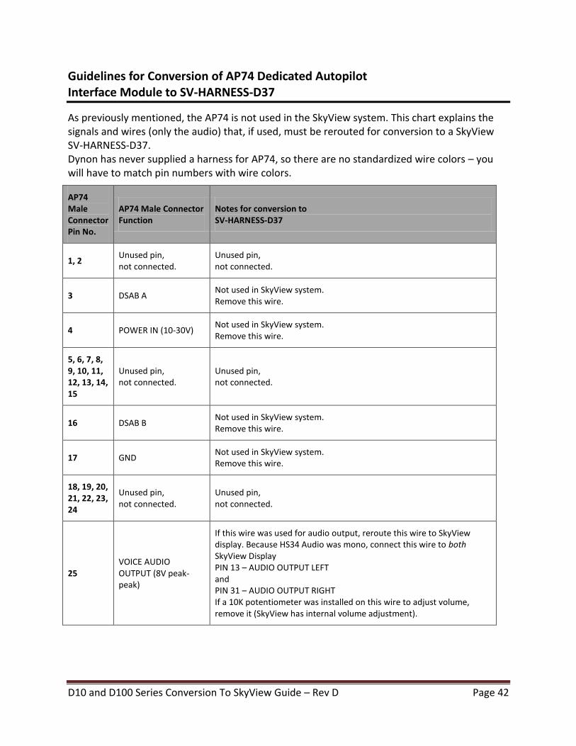
Guidelines for Conversion of AP74 Dedicated Autopilot Interface Module to SV-HARNESS-D37
As previously mentioned, the AP74 is not used in the SkyView system. This chart explains the signals and wires (only the audio) that, if used, must be rerouted for conversion to a SkyView SV-HARNESS-D37. Dynon has never supplied a harness for AP74, so there are no standardized wire colors – you will have to match pin numbers with wire colors.
AP74 Male Connector Pin No.
AP74 Male Connector Function
Notes for conversion to SV-HARNESS-D37
1, 2 Unused pin, not connected.
Unused pin, not connected.
3 DSAB A Not used in SkyView system. Remove this wire.
4 POWER IN (10-30V) Not used in SkyView system. Remove this wire.
5, 6, 7, 8, 9, 10, 11, 12, 13, 14, 15
Unused pin, not connected.
Unused pin, not connected.
16 DSAB B Not used in SkyView system. Remove this wire.
17 GND Not used in SkyView system. Remove this wire.
18, 19, 20, 21, 22, 23, 24
Unused pin, not connected.
Unused pin, not connected.
25 VOICE AUDIO OUTPUT (8V peak-peak)
If this wire was used for audio output, reroute this wire to SkyView display. Because HS34 Audio was mono, connect this wire to both SkyView Display PIN 13 – AUDIO OUTPUT LEFT and PIN 31 – AUDIO OUTPUT RIGHT If a 10K potentiometer was installed on this wire to adjust volume, remove it (SkyView has internal volume adjustment).
D10 and D100 Series Conversion To SkyView Guide – Rev D Page 43
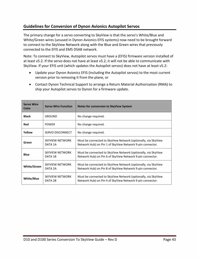
Guidelines for Conversion of Dynon Avionics Autopilot Servos
The primary change for a servo converting to SkyView is that the servo’s White/Blue and White/Green wires (unused in Dynon Avionics EFIS systems) now need to be brought forward to connect to the SkyView Network along with the Blue and Green wires that previously connected to the EFIS and EMS DSAB network.
Note: To connect to SkyView, Autopilot servos must have a (EFIS) firmware version installed of at least v5.2. If the servo does not have at least v5.2, it will not be able to communicate with SkyView. If your EFIS unit (which updates the Autopilot servos) does not have at least v5.2:
Update your Dynon Avionics EFIS (including the Autopilot servos) to the most current version prior to removing it from the plane, or
Contact Dynon Technical Support to arrange a Return Material Authorization (RMA) to ship your Autopilot servos to Dynon for a firmware update.
Servo Wire Color
Servo Wire Function Notes for conversion to SkyView System
Black GROUND No change required.
Red POWER No change required.
Yellow SERVO DISCONNECT No change required.
Green SKYVIEW NETWORK DATA 1A
Must be connected to SkyView Network (optionally, via SkyView Network Hub) on Pin 1 of SkyView Network 9-pin connector.
Blue SKYVIEW NETWORK DATA 1B
Must be connected to SkyView Network (optionally, via SkyView Network Hub) on Pin 6 of SkyView Network 9-pin connector.
White/Green SKYVIEW NETWORK DATA 2A
Must be connected to SkyView Network (optionally, via SkyView Network Hub) on Pin 8 of SkyView Network 9-pin connector.
White/Blue SKYVIEW NETWORK DATA 2B
Must be connected to SkyView Network (optionally, via SkyView Network Hub) on Pin 4 of SkyView Network 9-pin connector.
D10 and D100 Series Conversion To SkyView Guide – Rev D Page 44
Guidelines for Conversion of Accessories
The Dynon Heated AOA Pitot Probe Controller includes an output that is used to indicate failure of the heating system. Because of limited inputs on a Dynon Avionics EMS, this circuit was often wired to a separate indicator light. Because SkyView SV-EMS-220 has more available inputs, it is common to connect the “Heater Failure” output to the SV-EMS-220 which can then display the status of the “Heater Failure” (red, or green) on the SkyView EMS page. See the section regarding Contacts in the SkyView System Installation Guide.
If your plane has serial port connectors built-in to the panel (for firmware updates), those will no longer be used in conjunction with SkyView (except for the rare case of streaming data). Consider replacing panel-mounted serial connectors with panel-mounted female USB connectors for easy updating of your SkyView displays.
(End of document)