FLIGHT ENGINEER INITIAL QUALIFICATION Terminal Instrument ...
99
FlightSafety SERVICES CORPORATION FLIGHT ENGINEER INITIAL QUALIFICATION Terminal Instrument Procedures (TERPS) Workbook . . . - C-141 AIRCREW TRAINING SYSTEM For Purposes Only ... · ... · ... . ·. ;,: ·. . .
Transcript of FLIGHT ENGINEER INITIAL QUALIFICATION Terminal Instrument ...

FlightSafety SERVICES CORPORATION
----~
FLIGHT ENGINEER INITIAL QUALIFICATION
Terminal Instrument Procedures (TERPS)
Workbook
. . . -
C-141 AIRCREW TRAINING SYSTEM
For Tr~i.ning Purposes Only
... · ... · ... . ·. ;,: ·. . .

.!
FLIGHT ENGINEER CONTINUATION TRAINING UNIT: Normal Procedures LESSON: Terminal Instrument Procedures (TERPS) Workbook
FLIGHTSAFETY SERVICES CORPORATION WORKBOOK
FIQH5010
LIST OF EFFECTIVE PAGES
Original .............................. May 1999 Revision A ......................... Sep 1999 Change 1 ............................ Jun 2000 Revision B ......................... Nov 2000 TSCO # cPi { c_ - '-/ / ct
Nov 2000/Rev. B FOR TRAINING PURPOSES ONLY CAGE Code: 98747

FLIGHT ENGINEER CONTINUATION TRAINING UNIT: Normal Procedures LESSON: Terminal Instrument Procedures (TERPS) Workbook
FORWARD
FLIGHTSAFETY SERVICES CORPORATION WORKBOOK
FIQH5010
This workbook is designed to provide you with information, exercises, and self tests as part of your Terminal Instrument Procedures (TERPS) training.
Each flight engineer student must monitor at least one TERPS approach in the simulator. This can be done on DAY 2. The flight engineer and pilot instructors should coordinate the time of the approach. Each flight engineer is to brief the approach that he/she will monitor. During the approach the instructor will quiz the flight engineer with questions about the approach to ensure the engineer is monitoring the approach correctly.
Nov 2000/Rev. B FOR TRAINING PURPOSES ONLY

FLIGHT ENGINEER CONTINUATION TRAINING UNIT: Normal Procedures LESSON: Terminal Instrument Procedures (TERPS) Workbook
TABLE OF CONTENTS
FLIGHTSAFETY SERVICES CORPORATION WORKBOOK
FIQH5010
LIST OF FIGURES ........................................................................................................ VI
CHAPTER 1: GENERAL INFORMATION ..................................................................... 1 ST AN DAROS ........................................................................................................ 3 STANDARD DOD PUBLICATIONS ...................................................................... 4 AIRCRAFT NAVIGATION EQUIPMENT ............................................................... 6
VHF Navigation System .......................................................................... ~ .. 6 Glideslope Systems ................................................................................... 6 T ACAN Systems ........................................................................................ 6 ADF Systems ............................................................................................. 6 Marker Beacon Receiver ............................................................................ 7 Inertial Navigation System ......................................................................... 7 Fuel Savings Advisory System ................................................................... 7 Weather Radar System .............................................................................. 8 Combined Altitude Radar Altimeter System ............................................... 8 Flight Management System/Global Positioning System ............................. 8
INSTRUMENT TYPE APPROACHES .................................................................. 9 Precision Approaches ............................................................................... 9 Non Precision Approaches ........................................................................ 9 Instrument Approach Plate Components ................................................. 12
PLAN VIEW ........................................................................................................ 13 Tactical Air Navigation (T ACAN) .............................................................. 14 Very High Frequency Omnirange (VOR) .................................................. 14 VORTAC .................................................................................................. 14 Non Directional Beacon (NOB) ................................................................ 14 Navigational Aid Name, Radio Frequency, and Morse Code Identifier .... 15 Minimum Safe Altitude (MSA) .................................................................. 15 Emergency Safe Altitude (ESA) ............................................................... 16 Obstacles ................................................................................................. 16 Radio Frequencies ................................................................................... 17 Distance Circle ......................................................................................... 18 Enroute Navigational Facilities ................................................................. 19
PROFILE VIEW .................................................................................................. 21 Altitudes .................................................................................................. 21 Transition Level/Transition Altitude ......................................................... 22
MINIMA SECTION .............................................................................................. 23 Aircraft Approach Category ...................................................................... 24 Approach Categories ............................................................................... 24
Nov 2000/Rev. B FOR TRAINING PURPOSES ONLY iii

FLIGHTSAFETY SERVICES CORPORATION FLIGHT ENGINEER CONTINUATION TRAINING WORKBOOK FIQH5010
UNIT: Normal Procedures LESSON: Terminal Instrument Procedures (TERPS) Workbook
Approach Type ......................................................................................... 25 Visibility Minimums ................................................................................... 26
AIRPORT SKETCH ............................................................................................ 27 Airport Lighting ......................................................................................... 28 Runway End Identifier Lights (REIL) ....................................................... 28 Touchdown Zone Lighting (TDZ) ........................................................... 28 Centerline Lighting (CL) .......................................................................... 28 High Intensity Runway Lighting (HIRL) ................................................... 28
EXERCISE 1 ....................................................................................................... 30 Exercise 1 Answer Key ............................................................................ 34 Notes ........................................................................................................ 35
CHAPTER 2: BEARING DISTANCE HEADING INDICATOR AND HORIZONTAL SITUATION INDICATOR NAVIGATION ............................................................ 37 BEARING DISTANCE HEADING INDICATOR (BDHl) ....................................... 37 LUBBER LINE .................................................................................................... 38 BDHI POSITION ORIENTATION ........................................................................ 39 RADIAL VS. COURSE ........................................................................................ 42 HORIZONTAL SITUATION INDICATOR (HSl) ................................................... 45
Aircraft Heading ...................................................................................... 45 ~-Bearing Pointer ....................................................................................... 45 Course Arrow .......................................................................................... 45 Course Deviation Indicator (CDI) ........................................................... .46 Course Deviation Scale ........................................................................... 46 Heading Marker ....................................................................................... 46 Range Indicator ....................................................................................... 46 TO-FROM Indicator ................................................................................. 46
EXERCISE 2 ....................................................................................................... 47 Exercise 2 Answer Key ............................................................................ 51 Notes ........................................................................................................ 52
CHAPTER 3: DEPARTURE AND TERMINAL ARRIVAL. ........................................... 53 DEPARTURE ...................................................................................................... 53
Standard Instrument Departure ................................................................ 53 Departure Planning .................................................................................. 55 HQ AMC Airfield Suitability and Restrictions Report (ASRR) .................. 55 FLIP Enroute Supplement ....................................................................... 55 FLIP Terminal (High or Low Altitude) ...................................................... 55 Base Operations ..................................................................................... 55 Other Sources ......................................................................................... 56
TERMINAL ARRIVAL ......................................................................................... 57 .~ Feeder Facilities/Published Routings ....................................................... 57
STANDARD TERMINAL ARRIVALS (STARS) ................................................... 58
iv FOR TRAINING PURPOSES ONLY Nov 2000/Rev. B

FLIGHT ENGINEER CONTINUATION TRAINING FLIGHTSAFETY SERVICES CORPORATION UNIT: Normal Procedures . WORKBOOK LESSON: Terminal Instrument Procedures (TERPS) Workbook FIQH5010
EXERCISE 3 ....................................................................................................... 59 Exercise 3 Answer Key ............................................................................ 63 Notes ........................................................................................................ 64
CHAPTER 4: INSTRUMENT APPROACHES .................................................... : ........ 65 HIGH ALTITUDE BOOKS-................................................................................ 66 LOW ALTITUDE BOOKS - ................................................................................. 67 HIGH PENETRATIONS - ................................................................................... 68 PROCEDURE TURNS-..................................................................................... 69 HOLDING PATTERNS (IN LIEU OF PROCEDURE TURN)-............................ 70 PROCEDURE TRACKS - .................................................................................. 71 EXERCISE 4 ....................................................................................................... 72
Exercise 4 Answer Key ............................................................................ 75 Notes ........................................................................................................ 76
CHAPTER 5: INITIAL APPROACH FIX TO FINAL APPROACH FIX ......................... 77 INITIAL APPROACH FIX (IAF) ........................................................................... 77 DESCENT PROCEDURES ................................................................................ 78 EXERCISE 5 ....................................................................................................... 80
Exercise 5 Answer Key ............................................................................ 82 Notes ........................................................................................................ 83
CHAPTER 6: FINAL APPROACH ............................................................................... 85 PRECISION AND NON-PRECISION APPROACHES ........................................ 85
Precision Approach (ILS, PAR) ............................................................... 85 Non-Precision Approach (LOC, TAC, ASR, etc) ..................................... 85
VISUAL DESCENT POINT ................................................................................. 86 CIRCLING APPROACHES ................................................................................. 87 MISSED APPROACH ......................................................................................... 88 EXERCISE 6 ....................................................................................................... 89
Exercise 6 Answer Key ............................................................................ 90 FINAL THOUGHTS ............................................................................................. 91
A: GENERAL INFORMATION AND ABBREVIATIONS .............................................. 92
Nov 2000/Rev. B FOR TRAINING PURPOSES ONLY v

FLIGHTSAFETY SERVICES CORPORATION WORKBOOK FIQH5010
FLIGHT ENGINEER CONTINUATION TRAINING UNIT: Normal Procedures
LESSON: Terminal Instrument Procedures (TERPS) Workbook
LIST OF FIGURES
FIGURE 1: DOD FLIPS, ENROUTE AND TERMINAL ................................................. 4 FIGURE 2: FLIP (TERMINAL) DEPARTURE PLATE ................................................... 5 FIGURE 3: REGIONAL TERMINAL FLIPS .................................................................. 5 FIGURE 4: DOD APPROACH PLATE ........................................................................ 12 FIGURE 5: PLAN VIEW .............................................................................................. 13 FIGURE 6: NAVAID IDENTIFIER ............................................................................... 15 FIGURE 7: MSA CIRCLE ........................................................................................... 15 FIGURE 8: ESA .......................................................................................................... 16 FIGURE 9: OBSTACLES ............................................................................................ 16 FIGURE 10: COMMUNICATIONS ................................................................................ 17 FIGURE 11: DISTANCE CIRCLES .............................................................................. 18 FIGURE 12: ENROUTE NAVIGATIONAL FACILITIES ................................................ 19 FIGURE 13: LEGEND .................................................................................................. 20 FIGURE 14: PROFILE VIEW ....................................................................................... 21 FIGURE 15: ALTITUDES ............................................................................................. 21 FIGURE 16: TRANSITION LEVEL ............................................................................... 22 FIGURE 17: MINIMA .................................................................................................... 23 FIGURE 18: APPROACH CATEGORIES .................................................................... 24 FIGURE 19: APPROACH TYPE ................................................................................... 25 FIGURE 20: VISIBILITY REQUIREMENTS ................................................................. 26 FIGURE 21: AIRPORT SKETCH .................................................................................. 27 FIGURE 22: AIRPORT SKETCH .................................................................................. 28 FIGURE 23: APPROACH LIGHTING ........................................................................... 29 FIGURE 24: APPROACH PLATE ................................................................................. 33 FIGURE 25: BDHI COMPONENTS .............................................................................. 37 FIGURE 26: LUBBER LINE .......................................................................................... 38 FIGURE 27: BOHi POSITION ORIENTATION ............................................................. 39 FIGURE 28: BDHl/DME ............................................................................................... 40 FIGURE 29: BDHl/PLAN VIEW .................................................................................... 41 FIGURE 30: RADIAL .................................................................................................... 42 FIGURE 31: BOHi COURSE ........................................................................................ 43 FIGURE 32: BOHi COURSE ........................................................................................ 44 FIGURE 33: HSI ........................................................................................................... 45 FIGURE 34: HSI ........................................................................................................... 46 FIGURE 35: APPROACH PLATE ................................................................................. 49 FIGURE 36: INSTRUMENT INDICATIONS .................................................................. 50 FIGURE 37: SID ........................................................................................................... 54 ~ FIGURE 38: FEEDER FACILITIES .............................................................................. 57 FIGURE 39: STAR ....................................................................................................... 58
vi FOR TRAINING PURPOSES ONLY Nov 2000/Rev. B

FLIGHT ENGINEER CONTINUATION TRAINING FLIGHTSAFETY SERVICES CORPORATION UNIT: Normal Procedures LESSON: Terminal Instrument Procedures (TERPS) Workbook
WORKBOOK FIQH5010
FIGURE 40: SID .............................................................................................................. 60 FIGURE 41: APPROACH PLATE ................................................................................. 62 FIGURE 42: INSTRUMENT APPROACHES ................................................................ 65 FIGURE 43: HIGH ALTITUDE FLIP ............................................................................... 66 FIGURE 44: LOW ALTITUDE FLIP .............................................................................. 67 FIGURE 45: HIGH PENETRATION .............................................................................. 68 FIGURE 46: PROCEDURE TURNS ............................................................................. 69 FIGURE 47: HOLDING PATTERN ............................................................................... 70 FIGURE 48: PROCEDURE TRACKS ........................................................................... 71 FIGURE 49: INSTRUMENT APPROACHES ................................................................ 73 FIGURE 50: INSTRUMENT APPROACHES ................................................................ 74 FIGURE 51. INITIAL APPROACH FIX ......................................................................... 77 FIGURE 52: ALTITUDES ............................................................................................. 78 FIGURE 53: ALTITUDE DEPICTIONS ......................................................................... 79 FIGURE 54: APPROACH PLATE ................................................................................. 81 FIGURE 55: PRECISION APPROACH ........................................................................ 85 FIGURE 56: NON-PRECISION APPROACH ............................................................... 85 FIGURE 57: VDP .......................................................................................................... 86 FIGURE 58: CIRCLING APPROACH ........................................................................... 87 FIGURE 59: MISSED APPROACH .............................................................................. 88
Nov 2000/Rev. B FOR TRAIN1NG PURPOSES ONLY vii

FLIGHT ENGINEER CONTINUATION TRAINING FLIGHTSAFETY SERVICES CORPORATION UNIT: Normal Procedures . WORKBOOK LESSON: Terminal Instrument Procedures (TERPS) Workbook FIQH5010
CHAPTER 1: GENERAL INFORMATION
AFI 11-2C-141V1, C-141 Aircrew Training, established a new Terminal Instrument Procedures (TERPS) training requirement for C-141 flight engineers. The purpose of this training is to provide flight engineers with the knowledge and skills necessary to monitor the briefed departure and approach, and advise the pilots of any deviations that would compromise safety.
As a Flight Engineer, an essential part of your job on the flight deck is to monitor departure, enroute, and approach procedures. You are not required to be able to fly an instrument approach, however, you must be able to detect deviations from the briefed procedures. In order to accomplish that, you must understand some terminology, definitions, symbols, and procedures.
If any conflict exists between this text and the DoD Flight Information Publications (FLIP), then DoD guidance will take precedence.
You will require no additional materials to complete this workbook. You may wish to spend a few minutes with an actual approach book as you progress through this material. If you wish to use a glossary of terms, consult the front of the DoD Flight Information Publications, General Planning (GP). That document also contains a collection of abbreviations.
Training for flight engineers includes monitoring navigation equipment and pilot instruments for correct settings to ensure the departure and approach procedures are being accomplished as briefed. When you have completed this training you will be able to interpret FLIP documents to
• Locate the Plan View, Profile View, Minima Section, and Airport Sketch.
• Locate and list the frequencies for the ILS, VOR, TACAN, and NDB, and given a list of characteristics relating to navigational facilities, select those characteristics which relate to TACAN, VOR, and NDB facilities.
• Locate and list the emergency safe altitude within 100 NM of the navigation facility used for the approach and the minimum safe altitude within 25 NM of the specified NAVAID.
• Identify the symbols used to depict obstacles and their height above Mean Sea Level (MSL) on the approach plate's Plan View and Airport Sketch.
• Locate and list the UHF and VHF radio frequencies for Approach Control, Tower, Ground Control, and Automatic Terminal Information Service (ATIS.)
Nov 2000/Rev. B FOR TRAINING PURPOSES ONLY 1

FLIGHTSAFETY SERVICES CORPORATION FLIGHT ENGINEER CONTINUATION TRAINING WORKBOOK FIQH5010
UNIT: Normal Procedures LESSON: Terminal Instrument Procedures (TERPS) Workbook
2
• Locate the distance circle and list the significance of the solid inner circle line and the dashed outer circle line.
• List the magnetic radial (course), and distance from the depicted feeder facilities to the Initial Approach Fix (IAF) or holding fix, as appropriate.
• List the altitudes from the Initial Approach Fix (IAF) to the Final Approach Fix (FAF.)
• State the ceiling and visibility requirements for the intended approach.
• Determine the approach category for a given final approach speed.
• Using a Bearing Distance Heading Indicator (BOHi) or Horizontal Situation Indicator (HSI) with Distance Measuring Equipment (DME), state the aircraft position relative to a selected NAVAi D
• List the desired course to fly or track a VHF Omni-directional Range (VOR) or Tactical Air Navigation (TACAN) radial.
• State the routing, altitude, obstacles, climb gradient, and the fixed point, or location to which the aircraft is cleared.on a Standard Instrument Departure (SID).
• Identify the IAF.
• List the altitude restrictions from the Initial Approach Fix (IAF) to the Final Approach Fix (FAF) from a HI altitude approach plate and from a group of statements, select the statement which describes the approach procedures, or supply the requested information.
• List the altitude restrictions from the Initial Approach Fix (IAF) to the Final Approach Fix (FAF) from a LOW altitude approach plate, and from a group of statements, select the statement which describes the approach procedures, or supply the requested information.
• List the Minimum Descent Altitude (MDA) for a nonprecision approach and the Decision Height (DH) for a precision approach.
FOR TRAINING PURPOSES ONLY Nov 2000/Rev. B

~ ' '
FLIGHT ENGINEER CONTINUATION TRAINING FLIGHTSAFETY SERVICES CORPORATION UNIT: Normal Procedures . WORKBOOK LESSON: Terminal Instrument Procedures (TERPS) Workbook FIQH5010
STANDARDS
Train and evaluate Initial Qualification Flight Engineers to a B knowledge standard.
Train and evaluate Currently Qualified Flight Engineers to a C knowledge standard.
Individual can identify basic facts and terms about the subject and, when used with a
A Facts/Nomenclature performance code, can state nomenclature, simple facts, or procedures involved in an activity.
Individual can explain the relationship of basic facts and state general principles about the
B Principles/Procedures subject and, when used with a performance code, can determine step-by-step procedures for sets of activities.
Individual can analyze facts and principles ~. and draw conclusions about the subject and,
c Analysis/Operating when used with a performance code, can Principles describe why and when each activity must be
done and tell others how to accomplish activities.
Individual can evaluate conditions and create new rules or concepts about the subject and,
D Evaluation/Complete Theory when used with a performance code, can inspect, weigh, and design solutions related to the theory involved with activities.
Nov 2000/Rev. B FOR TRAINING PURPOSES ONLY 3

FLIGHTSAFETY SERVICES CORPORATION WORKBOOK FIQH5010
STANDARD DOD PUBLICATIONS
FLIGHT ENGINEER CONTINUATION TRAINING UNIT: Nonnal Procedures
LESSON: Tenninal Instrument Procedures (TERPS) Workbook
This chapter describes DoD instrument approach and departure publications. The types of booklets containing approach and departure information are classified as DoD Flight Information Publications or FLIPs. The two types of publications regularly used are "Enroute" and "Terminal" FLIPs. All DoD publications are designated by color for a specific world region (e.g., United States, White; Europe, North Africa, and Middle East, Green; Pacific, Yellow; etc).
Enroute FLIPs provide basic airfield information and flight procedures for US military air operations only. Typical information found in enroute FLIPs are an alphabetical listing of airfields, International Civil Aviation Organization (ICAO) identifiers, runway information, types of ground support, specific restrictions/cautions, available navigation aids, and a complete list of radio frequencies.
DOD FLIGHT INFORMATION PUBLICATION
(EN ROUTE)
e IFR ·SUPPLEMENT e UNITED STATES
Thia~ ltluuedMll'f ElGHTWIEKS •
EFFECTIVE0901Z 28 JAN 1999 TO 25 MAR 1999
TABLE OF CONTENTS fl>odolNo<looo .............................................. --c-o...i- ....................................................... I
-A;~__,.......,.,_o1c..c-..................... , -· -.,~__,.,_ .. -. ............................ ,
0¥..,,_0... __ ...................................... .., ·-· ....,.,,,-,-,.us .................................... 1-11
~--,.~ ............................... NM
..,...,,_,~.-................................ -.. -C:~• .... ci.-.....·T-al-. ........... , ........ C-1 --.-. ........................................... --c-
NATIONALIMAG~=~PING AGENCY 3200 SOUTH SECOND STREET
ST. LOUIS. MISSOURI 631111-3399
~~':.r~~s:J:',~
ll!9!!1JDlll --·NO. ENRXXUSIFRSP
DOD VOL·Z FUGHT INFORMATION PUBLICATION
ITERMlNAU LOW ALTITUDE UNITED STATES
AIRPORT DIAGRAMS INSTRUMENT APPROACH PROCEDURES
MILITARY DEPARTURE PROCEDURES RADAR INSTRUMENT APPROACH MINIMUMS
EFFECTIVE 28 JAN 99 TO :15MAR99
TCN EFFECTIVE 2S FU t9
Consult NOTAMS fOf latest information
l'Ul\ISM!O 1H ACC~f Wttlf '"Till-AGENCY A.'11 CIJITOGIUJ'dlC COMMITTEE SPECIFICATlO'IS ANO AGlllfMENTS-0\'ED IY
lllPAllTMENT Of DUENll * • DEPAllTMINT OF COMMHCE
•
UDlllAL AVIATION ADMINISTllATION Qj'I ~
l'lblis.'ledl:>i ~ llA110NAL IMAGERY AND MAIPING lllZll/l:.Y :!
mo soutH SlCOfG ST111ET i st LOllS. MISSCMll DllNnl ~
O~\SbrlMl.t>1ICISlaao...-ll • No~dofl>ed-TOl17US.C.
llOllDilllllll llDIBIH NSN 7641014005597 00
- 99028 TERMXUSUAPV02
390001.001
Figure 1: DoD FLIPs, Enroute and Terminal
Terminal FLIPs describe essential departure and arrival procedures, and depict airport diagrams, instrument approach procedures, standard instrument departures (military or
~··
civilian), radar instrument approach minimums, and standard terminal arrivals. The ~ approach and departure FLIPs are used for transition between the terminal area and world wide regions.
4 FOR TRAINING PURPOSES ONLY Nov 2000/Rev. B

FLIGHT ENGINEER CONTINUATION TRAINING FLIGHTSAFETY SERVICES CORPORATION UNIT: Normal Procedures . WORKBOOK LESSON: Terminal Instrument Procedures (TERPS) Workbook FIQH5010
ROasPRINGS.THREE DEPARTURE RSG3•RSG
DOD RJGHT IHRRM110N PUllUCATION
(TIRMllWJ
HIGH ALMUDE UNITED STATES AIRPORT DIAGRAMS
IN8TRUMENT APPROACH PAOCeDURU MIUT'AAY DEPARTURE PROCEDURll&
RADAR INSTRUMENT APPROACH MINIMUMS
• --b'I -_____ _,
----ST.LOUIS,-G11Nm
CC..,..'IM .. lfle\M'llldS..~ ho~~..,..,.nus.c. •
~rGS-THREE DEPARTURE
Figure 2: FLIP (TERMINAL) Departure Plate
Regional terminal FLIPs are broken down further by volumes. As examples, the "Low Altitude Terminal US" FLIPs come in 12 volumes covering the 48 contiguous United States, while the "High and Low Altitude Pacific and Australia,, terminal FLIPs come in three regional volumes. Changes and updates are issued on a published schedule, and are known as TCNs or Terminal Change Notices.
DDO VGA RJGlfT INl'OllMATION~
CTlllMINAU LOW ALTITUDE UNITED STATES
AlllPOllT DIACl-Ma INIT1'UMSNT APPllOACM PAOCIDUllll
MIUTAllY DIMllTUlll PllOCt!DUll.11 llADA" INIT1'UMllNT AP""OACH MINIMUMI
~~28JAN99 1011-..
1°'~11 ..... __ .,. __
DGO IW FUCIKI'~ l'USUCATION
t?ERMINAU HIGH ALTITUDE UNITED STATES
AIRl'Olr'FlllACl-
INITRllMEHI' APf'AOAClt -MU1'MYDIP~PAOCaDUMa AADMIH8TllUMan"_MI_
IDllllllantn UllB1 HSN 1141014I0115111 -- M050 -· URMllUSllAPSW
Figure 3: Regional Terminal FLIPs
Nov 2000/Rev. B FOR TRAINING PURPOSES ONLY
000 comw. RJCIKl'-l'IONPUILICA'l'ION ~
UNITED STATES Allll'Oln" DIAGllAMI
CMLSTANDARD INSTllUMINT DIMRl'ISRQ PROFIU DlllCINT PROCIDUllU ITANDAla> Tlll.MINM.AlllllVALI
IHICIM I OCT 98
tg ·-·
fUlllllHIUfl llGJHI NSH 1141014507702 .,. - IMIZlt ..,,. • TERMXS&OSTAAC
390002.001
5

FLIGHTSAFETY SERVICES CORPORATION WORKBOOK FIQH5010
AIRCRAFT NAVIGATION EQUIPMENT
FLIGHT ENGINEER CONTINUATION TRAINING UNIT: Normal Procedures
LESSON: Terminal Instrument Procedures (TERPS) Workbook
The navigation equipment installed in the C-141 aircraft consists of the VHF navigation (VOR), ILS localizer/glidepath, TACAN, ADF, marker beacon, INS, FSAS, radar, CARA, and in some instances FMS/GPS. The following systems information is provided for training purposes only. Consult T.O. 1C-141B-1 Flight Manual for specific system descriptions and operational procedures.
VHF Navigation System
These systems are capable of receiving signals for VOR and Instrument Landing System (ILS) approaches. The VOR radio stations will give bearing (direction) information and display it on the Horizontal Situation Indicator (HSI) and Bearing Distance Heading Indicator (BOHi). Additionally, steering information will be presented on the Attitude Direction Indicator (ADI) and HSI informing the pilots if they are left or right of course. The HSI also incorporates a pointer displaying flight direction either to or from the radio navigation station.
Glideslope Systems
The glideslope is an integral part of the VHF navigational systems whenever an ILS frequency is selected on the VHF navigation radio. The glideslope system displays glideslope pitch steering commands on the ADI only during an ILS approach.
TACAN Systems
Two Tactical Air Navigation or TACAN navigation systems are used to determine the relative bearing and distance to a selected station. The TACAN is the only navigational receiver capable of determining Distance Measuring Equipment (DME) from the radio station. Otherwise, TACANs and VORs are similar in that they both give steering information to the navigation instruments. Some TACAN stations provide DME only, no bearing.
ADF Systems
Two separate Automatic Direction Finder (ADF) systems are capable of receiving bearing information for display on the BOHi. A bearing pointer shows the direction to the transmitter.
6 FOR TRAINING PURPOSES ONLY Nov 2000/Rev. B

FLIGHT ENGINEER CONTINUATION TRAINING FLIGHTSAFETY SERVICES CORPORATION UNIT: Normal Procedures LESSON: Terminal Instrument Procedures (TERPS) Workbook
WORKBOOK FIQH5010
Marker Beacon Receiver
The marker beacon receiver is an integral part of the VHF navigational system and is automatically tuned whenever an ILS frequency is selected on the VHF navigation radio. The marker beacons illuminate whenever the aircraft flies over the marker beacon transmitters during an ILS approach. The marker beacons will illuminate as an 0 {outer), M {middle), and I {inner) on the sky portion of the ADI on the C Model. (Marker Beacon Light (0, Mand I) illuminate on the C141B Model).
Inertial Navigation System
The I NS continuously computes horizontal navigation data and senses aircraft attitude in pitch, roll, and yaw axes, sending aircraft position and airspeed information to the appropriate avionics components. Other functions of the INS calculate wind speed, direction, and the amount of drift off course. The INS incorporates a 10-position data selector switch. Several of the functions may be used during the approach and are described as follows:
TK/GS - Present track and ground speed. Track is defined as the ground path {in degrees) the aircraft is traveling, not the direction the nose is pointing. Ground speed is defined as true airspeed corrected for wind.
HOG/DA - Heading and drift angle. Heading is defined as the direction {in degrees) the nose of the aircraft is pointed. Drift angle is displayed in degrees as left, right, or zero, and is a function of wind velocity and direction.
WIND - True wind direction and speed are indicated in the data displays when aircraft speed is 100 knots or greater {inflight).
Fuel Savings Advisory System
The Fuel Savings Advisory System {FSAS) interfaces with and controls either INS 1 or INS 2 {as selected). It provides flight operations advisories, radar indicator displays, windshear warning, altitude alert, and coupling to autopilot/autothrottle systems for altitude and airspeed control. Major components of the FSAS are the Display Interface Control Unit {DICU), Windshear and Altitude Alert Lights, FSAS/INS CDU, and the FMS/GPS on the C-141C.
DICU (C-141 B) - The DICU controls radar displays, annunciates FSAS modes, and allows selection of altitude alert targets. It also allows for the selection of various SKE modes on the radar screen.
Nov 2000/Rev. B FOR TRAINING PURPOSES ONLY 7

FLIGHTSAFETY SERVICES CORPORATION FLIGHT ENGINEER CONTINUATION TRAINING WORKBOOK FIQH5010
UNIT: Normal Procedures LESSON: Tenninal Instrument Procedures (TERPS) Workbook
DICU (C-141 C) - The DICU controls radar displays and annunciates FSAS modes. It also allows for the selection of various SKE modes on the radar screen.
Windshear Alert Lights (C-141B) - Two red colored WINDSHEAR lights illuminate when a windshear condition is encountered during an approach. There is an audible windshear warning when actual ground speed is 15 knots less than reference ground speed.
Windshear and Altitude Alert Lights (C-141C) - The Ground Collision Avoidance System (GCAS) mode 7 provides aural and visual warnings when a windshear condition is detected during low altitude phases of flight. When a windshear is detected, the Ground Collision Avoidance Panel (GCAP) displays a red backlit WINDSHEAR annunciator and the aural warning "WINDSHEAR, WINDSHEAR, WINDSHEAR" is announced over the GCAS speaker.
FSAS/INS CDU - The Control/Display Unit serves as the main interface for entering and displaying all FSAS and INS navigation data.
WEATHER RADAR SYSTEM
The primary purpose of the weather radar system is to provide weather avoidance information. During an approach, the radar receives input from the FSAS and displays the airfield location on the screen. Aircraft ground speed and reference ground speed are displayed on the lower right hand corner of the screen when approach/landing mode is selected in the FSAS.
COMBINED ALTITUDE RADAR ALTIMETER SYSTEM
The Combined Altitude Radar Altimeter (CARA) system provides accurate indications of aircraft altitude from 0 to 50,000 feet Above Ground Level (AGL). Altitude is indicated by a dial type pointer and a five digit LED display. Signals generated by the transceiver are transmitted and received by two flush mounted antennas located on the bottom aft portion of the left main gear pod.
FLIGHT MANAGEMENT SYSTEM/GLOBAL POSITIONING SYSTEM
The Flight Management System (FMS)/Global Positioning System (GPS) is the latest modification to the aircraft. It works like the INS System but uses global satellite signals to keep the INS computers constantly updated as to their position. This makes the INS more accurate as a navigational tool. ('.,
8 FOR TRAINING PURPOSES ONLY Nov 2000/Rev. B

FLIGHT ENGINEER CONTINUATION TRAINING FLIGHTSAFETY SERVICES CORPORATION UNIT: Normal Procedures LESSON: Tennlnal Instrument Procedures (TERPS) Workbook
WORKBOOK FIQH5010
INSTRUMENT TYPE APPROACHES
When discussing instrument approaches it is important to distinguish between precision and non precision approaches. Precision approaches provide both course and glideslope information. Non precision approaches provide course information only. These approaches are guided by either ground based radar equipment via voice instructions or from the aircraft avionics equipment. This chapter provides a brief definition of the different types of approaches.
PRECISION APPROACHES • (PAR/ILS)
Precision Approach Radar- Precision Approach Radar (PAR) approaches provide the pilot with precise course, glideslope, and range information. This type of approach is provided solely by voice instructions from the approach or radar controller. The controller issues course and glide path guidance, frequently informing the pilot of any deviations. The precision radar is accurate normally from 8 miles to touchdown.
Instrument Landing System - Instrument Landing System {ILS) approaches are designed to provide exact runway alignment and descent glide path indications. Both the ADI and HSI are used to determine proper direction and glide path to the runway. At some locations, DME is associated with ILS equipment to provide distance information to the navigational aid. (This DME cannot be received on the C-141 ).
Distance Measuring Equipment - Distance Measuring Equipment (DME) is the straight line distance from the aircraft to a selected ground station. DME is expressed in nautical miles and displayed on the HSI or BOHi when TACAN is selected.
NON PRECISION APPROACHES (ASR, VOR, VOR/DME, TACAN, NOB, Localizer)
Airport Surveillance Radar - The Airport Surveillance Radar (ASR) approach is very similar to the PAR with the exception that no glideslope information is given. Instead of flying a glideslope, pilots descend to a minimum descent altitude (MDA) until the runway can be visually acquired.
VHF Omni-Directional Range -The VHF Omni-Directional Range (VOR) is used to provide course or bearing information to align the aircraft with the runway centerline.
Nov 2000/Rev. B FOR TRAINING PURPOSES ONLY 9

FLIGHTSAFETY SERVICES CORPORATION FLIGHT ENGINEER CONTINUATION TRAINING WORKBOOK FIQH5010
UNIT: Normal Procedures LESSON: Terminal Instrument Procedures (TERPS) Workbook
10
Tactical Air Navigation - Tactical Air Navigation (TACAN) is used to provide course or bearing and runway alignment information similar to a VOR, but operates on a UHF frequency. Unlike the VOR, a TACAN is capable of receiving DME information for display on the HSI or BOHi when TACAN is selected.
VOR/DME - VOR/DME provides VHF bearing signals for runway alignment and UHF DME information from co-located VOR/DME equipment. It is basically a VOR and TACAN station located together, also known as a VORTAC.
Non-Directional Beacon - Non-Directional Beacon (NOB) is a low to high frequency radio beacon which transmits nondirectional signals. Aircraft use NOB signals to determine and display bearing information to any radio station.
Localizer - The Localizer approach is an ILS without the glideslope information. Localizer directional aids may not always be aligned as a straight in approach.
FOR TRAINING PURPOSES ONLY Nov 2000/Rev. B

FLIGHT ENGINEER CONTINUATION TRAINING UNIT: Normal Procedures LESSON: Terminal Instrument Procedures (TERPS) Workbook
NOTES
FLIGHTSAFETY SERVICES CORPORATION WORKBOOK
FIQH5010
Nov 2000/Rev. B FOR TRAINING PURPOSES ONLY 11

FLIGHTSAFETY SERVICES CORPORATION FLIGHT ENGINEER CONTINUATION TRAINING WORKBOOK FIQH5010
UNIT: Nonnal Procedures LESSON: Tenninal Instrument Procedures (TERPS) Workbook
INSTRUMENT APPROACH PLATE COMPONENTS
In this section, we will address the components and particulars of standard DoD approach plates.
12
96258
ILS RWY 17R ATIS * 273.5 ALTUS APP CON 125.1348.3 ALTUS TOWER 119.65255.6 GNOCON 121.85 275.8
AL-482. (USAF)
LTS@ /RADAR
LTS@ /RADAR
01644
0
1494
2180
~~ .... ~100 __ .a-=l:..=:~::.:..:35~~---· ....I LOCALIZER 111.3 I-ALT ~-·
IA 1720
I 1! ~
ALTUS AFB (Kl TS) ALTUS, OKLAHOMA
HOBART 111.&HBR ==-~·
awiss
\
\ \ \ \ \ \ I I I I
\ I ~~~ I ~~ I ~ \.;i WICHITA
/ FALLS
/ f /
'-, 'ffb ' E DME OR RADAR REQUIRE NOTE: Maximum holding i _t_ r.;;-. .,,..,.. "" airspeed 230 Kt; .._ l...,: •• -' Ui11 LTS _ _..
EMERG SAFE ALT 100 NM 4900 - - C - - -
MISSED APPROACH Clfmb to 4000 direct OKKIE
and hold
VORTAC
'· S.ILS 17R"
S·LOC 17R00 1740/24 361 (400-112)
c D 200
1740/40 381 (400·314)
E
CIRCLING"" 1760-1 1840·1 1840-1112 1940·2 1980-2 378(400-1) 459(S00-1) 458(S00-1 112) 558(600-2) 598(60G-2)
S-PAR 17R 1578124 200 200-ltz GS2.s•
• When ALS !nop, Increase RVR to 40 an vis to 3'4 mile. •• When ALS lnop, increase ABC RVR to so and vis to 1 mile,
CAT DE RVR to 60 and vis to 1\14 miles. ••• Circling not authorized W of Rwy 17R-35L.
ILS RWY 17R . 34•40'N·W16W
ELEV 1382
HIRL Rwy 17R-35L. 17L-35R, and Assaull Strip
FAF to MAP 4.4 NM Knots 60 90 120 150 180 Mln:Sac 4:24 2:58 2:12 1 :48 1 :28
ALTUS, OKLAHOMA ALTUS AFB (KLTS)
390003.001
Figure 4: DoD Approach Plate
FOR TRAINING PURPOSES ONLY Nov 2000/Rev. B

FLIGHT ENGINEER CONTINUATION TRAINING FLIGHTSAFETY SERVICES CORPORATION UNIT: Normal Procedures LESSON: Terminal Instrument Procedures (TERPS) Workbook
WORKBOOK FIQH5010
98258
ILS RWY 17R ATIS * 273.5 ALTUS APP CON 125.1348.3 ALTUS TOWER 119.65 255.6 GNDCON 121.85275.8
PLAN VIEW
AL-482. (USAF)
1.1.1792
LTS ID /RADAR
LTS ID /RADAR
01644
01494
ALTUS AFB (KL TS) ALTUS, OKLAHOMA
HOBART 111.SHBR ~:·
aianss
' \ \ \ \ \ \ I I I I
\ I 16'~~ /
':I \.j WICHITA
/ FALLS
/ /
DME OR RADAR REQUIRED
390004.001
Figure 5: Plan View
The Plan View (Fig. 5) is the largest block on the approach plate and represents the track of the approach as it would be seen by someone looking down from directly overhead. The top of the Plan View is always oriented towards north. This block contains a variety of information and symbols. The legend for these and other approach plate symbols is found at the front of the approach booklet.
Above the Plan View, in the upper left hand corner of the approach plate, is the approach name. The name identifies the type of navigational aid or aids which provide
~ final approach guidance and the runway to which the final approach course is aligned. When the name of the approach is followed by a letter such as A, 8, C, etc, the approach is designed for circling minimums only (VORA, TAC 8, NOB C, etc).
Nov 2000/Rev. B FOR TRAINING PURPOSES ONLY 13

FLIGHTSAFETY SERVICES CORPORATION WORKBOOK FIQH5010
FLIGHT ENGINEER CONTINUATION TRAINING UNIT: Nonnal Procedures
LESSON: Tenninal Instrument Procedures (TERPS) Workbook
Although the list of items is not all inclusive, the Approach Plate Plan View contains these important items.
Tactical Air Navigation (TACAN)
TACAN stations provide signals which allow airborne equipment to display a magnetic radial from the station and selected courses to or from the station. A TACAN station also includes Distance Measuring Equipment (DME) which shows the distance in nautical miles from the aircraft present position to the station. TACAN stations transmit in the Ultra High Frequency (UHF) range of radio frequencies. TACANs are usually associated with military installations.
Very High Frequency Omnirange (VOR) 0 As you probably have guessed by its name, a VOR station transmits in the VHF range of radio frequencies. VOR operation is essentially the same as a TACAN, except the VOR alone does not have DME.
VORTAC
Many VOR and TACAN stations are co-located. These are known as VORTAC stations. VORTACs have DME.
Non Directional Beacon (NOB) *symbols
A low or medium frequency radio beacon transmits nondirectional signals whereby the pilot of an aircraft properly equipped can determine bearings and "home" on the station. These facilities normally operate in the frequency band of 190 to 535 kHz and transmit a continuous carrier with either 400 or 1020 Hz modulation. All radio beacons except ~ the compass locators transmit a continuous three-letter identification in code except during voice transmissions.
14 FOR TRAINING PURPOSES ONLY Nov 2000/Rev. B

FLIGHT ENGINEER CONTINUATION TRAINING FLIGHTSAFETY SERVICES CORPORATION UNIT: Normal Procedures . WORKBOOK LESSON: Terminal Instrument Procedures (TERPS) Workbook FIQH5010
Navigational Aid Name, Radio Frequency, and Morse Code Identifier
The Plan View provides a convenient setting to display navigational aid information such as name, radio frequency, identifier, Morse code identifier, and channel.
ALTUS 109.8 L TS H:. •
Chan 35 390005.001
Figure 6: NAVAID Identifier
Minimum Safe Altitude (MSA)
This altitude provides at least 1 ,000 feet of obstacle clearance for emergency use within 25 nautical miles of the facility.
\ . .\S 25 ~ ~C:J~ . ~
)'U? rJo I 3aoo I ~
-132-00-1 Q 0 JI " ~ u>
~ I 3000 I )'Oo
390008.001
Figure 7: MSA Circle
Nov 2000/Rev. B FOR TRAINING PURPOSES ONLY 15

FLIGHTSAFETY SERVICES CORPORATION FLIGHT ENGINEER CONTINUATION TRAINING WORKBOOK FIQH5010
UNIT: Normal Procedures LESSON: Tennlnal Instrument Procedures (TERPS) Workbook
Emergency Safe Altitude (ESA)
This altitude provides 1,000 feet of obstacle clearance (2,000 feet in designated mountainous areas) within 100 nautical miles of the facility.
Obstacles
NOTE: Maximum airspeed 230 lets.
EMERG SAFE ALT 100 NM 4900
Figure 8: ESA
Obstacles and terrain are depicted on the approach plates by various symbols (Fig. 9).
• Spot Elevation • Highest Spot Elevation
~Obstacle .A Group of Obstacles /.\ Highest Obstacle
± Doubtful Accuracy
FootnoteG),@, etc., defines obstruction
controlling Minimum Climb Rate
Figure 9: Obstacles
390007.001A
Obstacles are measured in feet above Mean Sea Level (MSL). All distances given are from the departure end of the runway. Flying an approach exactly as depicted will assure obstacle clearance for the applicable category aircraft.
!~
Obstacles become a factor if they are located outside the guaranteed clearance area ~ and the aircraft is flying off track or VFR.
16 FOR TRAINING PURPOSES ONLY Nov 2000/Rev. B

FLIGHT ENGINEER CONTINUATION TRAINING FLIGHTSAFETY SERVICES CORPORATION UNIT: Normal Procedures LESSON: Terminal Instrument Procedures (TERPS) Workbook
Radio Frequencies
WORKBOOK FIQH5010
The upper left comer of the plan view has the appropriate controlling agency's VHF and UHF communication frequencies. Also included is the ATIS frequency where applicable.
Automatic Terminal Information Service (ATIS)-The continuous broadcast of recorded, non-control information in selected high activity (density) areas. Its purpose is to improve controller effectiveness, and to relieve frequency congestion by automating the repetitive transmission of essential but routine information.
.. , ....
Nov 2000/Rev. B
ATIS* 273.5 ALTUS APP CON 125.1 348.3 / ALTUS TOWER 119.65 255.6 / GND CON / L'~C:J
~~ 121.05 215.0 I ,, CLNCDEL <JI 120.6s 316.9 I ~'t' ASR/PAR I §
I ~ $ I
390009.001
Figure 10: Communications
FOR TRAINING PURPOSES ONLY 17

FLIGHTSAFETY SERVICES CORPORATION FLIGHT ENGINEER CONTINUATION TRAINING WORKBOOK FIQH5010
Distance Circle
UNIT: Normal Procedures LESSON: Terminal Instrument Procedures (TERPS) Workbook
On the Plan View of the Approach Chart there is a solid lined "Inner Circle." It is usually 10 NM or 20 NM in radius, but could be as small as 5 NM for helicopters. The distances inside the INNER circle are normally to scale. If not, a note NOT TO SCALE will be on the DISTANCE circle.
-Hl-TACAN RWY 15
fMBG SAR ALT 'ICJO NM DIG
Figure 11 : Distance Circles
Normally, the 20 NM circle is for HIGH Altitude Approaches; the 10 NM circle is for LOW Altitude Approaches.
390010.001
18 FOR TRAINING PURPOSES ONLY Nov 2000/Rev. B

FLIGHT ENGINEER CONTINUATION TRAINING FLIGHTSAFETY SERVICES CORPORATION UNIT: Normal Procedures LESSON: Terminal Instrument Procedures (TERPS) Workbook
Enroute Navigational Facilities
WORKBOOK FIQH5010
On the Plan View of the approach plate there can be an outer dashed circle labeled "Enroute Facilities" (Fig. 12). On the Enroute Facilities circle are symbols for enroute navigational aids. From each navigational aid there is an arrow depicting the terminal routing to the Initial Approach Fix (IAF). Each routing will be annotated with minimum en route altitude, the course, and distance to the IAF. The distances indicated within the terminal approach routing are NOT TO SCALE.
NOTE: All courses and directions on the approach plate will be MAGNETIC unless otherwise noted.
m~ ~
ILS RWY 21L (CAT II) Al-488.01 (USAF)
ATIS WILLIAMs~O- - -- > 116.4 384.9 ~ , ..... -------~ TRAVIS APP CON / -;-<6 ...,..4 '-.... 119.9 (S) 126.6 (N) 291.0 / ; \ 8 ... " TRAVIS TO.VIER / 120.75 255.9 / GND CON L'11 121.8 289.4 ~ QNC DEL /..~ 121.ss 335.s/t.c.'"
ASR I I f
\ SCAGGS ~0 ISLAV---ffo't A) \:,
" " ............
l ...
/ 1800211° /
No PT to VO' (6.3) i
--..- ~AF· r I !JM w~v1s;ti i I I
I J \
-.._ EMERG SAFE ALT 100 NM 13.200 FROM "TZZ" VOR
TRAVIS AFB (KSUU) FAIRFIELD, CALCFORNIA
\
' I I
390011.001
Figure 12: Enroute Navigational Facilities
Nov 2000/Rev. B FOR TRAINING PURPOSES ONLY 19

FLIGHTSAFETY SERVICES CORPORATION FLIGHT ENGINEER CONTINUATION TRAINING WORKBOOK FIQH5010
UNIT: Normal Procedures LESSON: Terminal Instrument Procedures (TERPS) Workbook
For additional symbols in the Plan View section of the approach plate, consult the legend in the front of any approach book.
20
LEGEND INSTRUMENT APPROACH PROCEDURES (CHARTS)
PLANVIEW SYMBOLS TERMINAL ROUTES SPECIAL USE AIRSPACE ..
Procedure Track tllHHHetHllllHlllHHlllHI~
Missed Approach
165° .... /~345°
Procedure Tum (Type, degree and point
of tum optlonaQ
-----~ Visual Flight Path
3100 NoPT 5.6 NM to GS lntcpt
------------ 0450--------~ .. ~-/ (14.2toLOM)
Minimum Altltude
~2000 .0. -------- 155° .. FeederRoute (15.1) Mileage / ~
Penetrates Special Use Airspace
HOLDING PATTERNS
C 27J Holding In lieu of
090• Procedure Tum
090" Anival
c~~::~ ;·"~'"""'<c. Missed I ) Approach ''""" 210......,... Holding Limits wlll only be specttled when they deviate from the standard. DME fixes may be shown.
REPORTING POINT/FIXES Reporting Point A Name (Compulsory) xFlx or ~ Name (Non-compulsoiy) Intersection
1@ DME Mileage ARCIDME/ANAV Fix ~
---R-198-----l .. ~::::!/~ ---LR-198 .. Lead Radial
(Arrows on distance circle Identify sectors)
OBSTACLES • Spot Elevation
/.\ Obstacle
~Highest Obstacle
• Highest Spot Elevation
A Group of Obstacles
± Doubtful Accuracy
R • Restricted W. Warning P • Prohibited A· Alert D· Danger
RADIO AIDS TO NAVIGATION llQJ Underline Indicates No Voice transmitted on
this frequency
Q,OR DvoRJDME QACAN Q,ORTAC
~~1}}!> LOM (Compass Locator at Outer Marker)
~ <23>@ Marker Beacons
_A_ WAYPOINT(WPT) Y __ w...;.a.:.::;yp...;.oi...;.nt...;.D...;.at;.;;.a __
PRAYS N38°58.30' wa9•s1.50• 112.7CAP 187.W56.2
590----' Waypoint Name,
Coordinates. Frequency, Identifier, RadlaVDlstance,
(Facmty to Waypolnt) Reference Fac!llty Elevation
h'"" .. ",...".·'""'~· .. · Localizer (LOC/LDA) Course
MLS Identifier
G!lclepath 6.20° Azimuth 01° (R)
l!!I DME111.15Chan48 li:il LOCIDME
e LOC/LDNSDF/MLS Transmitter (shown when Installation Is offset from its nonnal position off the end of the runway)
Primary Nav Aid Secondary with coordinate values Nav Aid
LIMA ~MM 1li:§ UM i&..:0
LIMA 248 NT=·
s12°00.80' W77°07.00
MISCELLANEOUS J VOR Changeover Point Rwy End Coordinates ,,.,,,
1 s12·00 52· I @ Helicopter Alighting Area Rwy 15 W77°oS.91'.
~ Distance Not to Scale - - - - - lntematlonal Boundary
390012.001
Figure 13: Legend
FOR TRAINING PURPOSES ONLY Nov 2000/Rev. B
I

FLIGHT ENGINEER CONTINUATION TRAINING FLIGHTSAFETY SERVICES CORPORATION UNIT: Normal Procedures LESSON: Terminal Instrument Procedures (TERPS) Workbook
WORKBOOK FIQH5010
PROFILE VIEW ZOCKS BLAIR R-262 R-348 [ill [ill
I L.,~ ® 4000 I I ~04'.~
I 3QQQ I 7 I I
:-[ii)Arc---1 I I
29001 -1 I I
Figure 14: Profile View
MISSED APPROACH Climb to 4000 direct
HESS and hold
~ I
VORTAC
[§) I ~ I ,:.; .. ~ .....
,,,,,. ""'"'''''' 390013.001
The Profile View (Fig. 14) is located below the Plan View, and just to the left of the Airport Sketch. An observer standing to one side of the airport would see the movement of the aircraft as represented in the Profile View. This allows us to consider the approach in a three dimensional way by showing the effect of altitude changes. If you mentally follow the aircraft on both the Plan View and the Profile View simultaneously, you will be situationally aware of the aircraft position at all times. The Profile View contains the following:
Altitudes-There are four types of altitudes: Mandatory, Minimum, Maximum, and Recommended. The legend for these altitudes is in the front of the Approach Booklet. Note that altitudes in the Profile View of the approach will be marked as indicated in the approach legend below.
Nov 2000/Rev. B
Altitude
5.500 Mandatory Altitude
2.500 Minimum Altitude
4,300 Maximum Altitude
3,000 Recommended Altitude
(1, 755) QFE Height (An absolute altitude, or height above the ground)
Figure 15: Altitudes
FOR TRAINING PURPOSES ONLY 21

FLIGHTSAFETY SERVICES CORPORATION FLIGHT ENGINEER CONTINUATION TRAINING WORKBOOK FIQH5010
UNIT: Normal Procedures LESSON: Terminal Instrument Procedures (TERPS) Workbook
Transition Level/Transition Altitude -
At most overseas locations, the transition altitude (TA), and in some cases, the Transition Level (TLV), appear in the Profile View.
TA 3000 MISSED APPROACH VOR/OME Climb on R-310 at 7 OME tum
right to TUC VORIDME at 3000C ... ~ 3000fl
J--- ~ 292° ......-,-~
~ I ...........
TLV FL 130 TA 11,000
R-198 ID 3700 ~ LI
(3681) ~I l2soo ~ ~2481 ) I 018°
I I
NOTE: In the CONUS, TA= 18,000 feet, TLV =FL 180
MISSED APPROACH Climb straight ahead
to 1500, tum right back to FAF or
VORIDME as directed
~ ··········••·
The correct altimeter setting is critical for maintaining clearance from other aircraft, and the ground! The C-141 Dash One, Section 2, contains altimeter setting procedures specific to each crew position. QNE (29.92) is set at higher altitudes to define flight levels; QNH (local) is set at the lower altitudes to assure a known altitude above mean sea level (MSL).
The changeover point during the climbout is always the designated Transition Altitude (TA). Set 29.92 (QNE) as an altimeter setting when passing the transition altitude.
~ ~---- TA
71///////////
The changeover point during the descent is the transition level (TLV). Set the local altimeter (QNH) when operating below the transition level.
I Set MSL ~ocal) I TLV
Figure 16: Transition Level
If the TL V is not printed in the profile view, it is because it varies with atmospheric conditions. It can be obtained from the ATIS or approach control.
22 FOR TRAINING PURPOSES ONLY Nov 2000/Rev. B

FLIGHT ENGINEER CONTINUATION TRAINING FLIGHTSAFETY SERVICES CORPORATION UNIT: Normal Procedures LESSON: Terminal Instrument Procedures (TERPS) Workbook
WORKBOOK FIQH5010
MINIMA SECTION
This section is found below the profile view to the left of the airport sketch. It usually has several lines of information corresponding to the various types of approaches which may be flown using each plate.
CATEGORY A B c D E
S-ILS 17R* 1579/24 200 (200-1fl)
S-LOC 17R** 1740/24 361 (400-112) 17 40/40 361 (400-314)
CIRCLING*** 1760-1 1840-1 1840-1112 1940-2 1980-2
378 (400-1) 459 (500-1) 458 (500-1 1r.z) 558 (600-2) 598 (600-2)
S-PAR 17R 1578/24 200 (200-112) GS 2.5°
* When ALS inop, increase RVR to 40 an vis to 314 mile. ** When ALS inop, increase ABC RVR to 50 and vis to 1 mile,
CAT DE RVR to 60 and vis to 1114 miles. *** Circling not authorized W of Rwy 17R-35L.
390017.001
Figure 17: Minima
Crewmembers should cross-check briefed approach minimums for accuracy. Crew members. also are responsible to ensure altimeter and radar altimeter bugs are set correctly to the approach minimums for the approach being flown.
Nov 2000/Rev. B FOR TRAINING PURPOSES ONLY 23

FLIGHTSAFETY SERVICES CORPORATION FLIGHT ENGINEER CONTINUATION TRAINING WORKBOOK FIQH5010
UNIT: Normal Procedures LESSON: Terminal Instrument Procedures (TERPS) Workbook
Aircraft Approach Category
The category line determines the minimums used based on the aircraft speed during the final portion of the instrument approach. An aircraft may use minimums for a higher category but cannot use minimums for a lower category (i.e. D may use E minimums but D can never use C minimums). The C-141 is normally a category D aircraft.
A B c D E
Figure 18: Approach Categories
Approach Categories
Aircraft performance differences have a direct effect on the airspace and visibility needed to perform certain maneuvers, such as circle to land, turning missed ~ approaches, final alignment correction to land, and descent. Approach categories are explained below.
Category A: speed less the 91 knots
Category B: speed 91 knots or more but less than 121 knots
Category C: speed 121 knots or more but less than 141 knots
Category D: speed 141 knots or more but less than 166 knots
Category E: speed 166 knots or more
24 FOR TRAINING PURPOSES ONLY Nov 2000/Rev. B

FLIGHT ENGINEER CONTINUATION TRAINING FLIGHTSAFETY SERVICES CORPORATION UNIT: Normal Procedures LESSON: Terminal Instrument Procedures (TERPS) Workbook
WORKBOOK FIQH5010
Approach Type
Landing minima are provided for three types of approaches: PRECISION, NONPRECISION, and CIRCLING.
The PRECISION APPROACH provides a vertical flight path using an approved procedure where the navigation facility is precisely aligned with the runway centerline. Glideslope and azimuth information are provided. For example, Precision Approach Radar (PAR) and Instrument Landing System (ILS) approaches are PRECISION approaches.
A NON-PRECISION APPROACH has course and range information or course information only; a glideslope is not used (LOC, TAC, VOR, ASR, NOB).
The CIRCLING APPROACH is a combination of an instrument and a visual flight maneuver. An instrument approach is used to acquire the runway environment, and the aircraft is flown visually to the landing runway. The landing runway may be a different runway than the one to which the instrument approach was made.
A radar approach can be either a precision or non precision approach. It relies upon a radar controller vectoring the aircraft to the approach runway (ASR, PAR).
CATEGORY
S-ILS 27
S-LOC 27
CIRCLING
S-PAR 27
Figure 19: Approach Type
Nov 2000/Rev. B FOR TRAINING PURPOSES ONLY 25

FLIGHTSAFETY SERVICES CORPORATION FLIGHT ENGINEER CONTINUATION TRAINING WORKBOOK FIQH5010
UNIT: Normal Procedures LESSON: Terminal Instrument Procedures (TERPS) Workbook
Visibility Minimums
RUNWAY VISUAL RANGE (RVR) is an instrumentally derived value representing the distance a pilot should see down the runway from the approach end. RVR is horizontal and NOT slant visual range. It is measured in hundreds of feet or meters as determined by country. RVR is used to determine the field conditions for straight-in approaches to that runway.
PREVAILING VISIBILITY (PV) is the greatest horizontal visibility equaled or exceeded throughout at least half of the horizon circle. PV is measured in statute miles, fractions of miles or meters, and MUST be used for circling approaches.
Aircraft Category
Decision Helght(DH)
MSL
•Prevailing Visibility I RVR (RVR In 100s
of feet)
Height of DH above touchdown
zone (HAT)
c
Celling In feet & Prevail!ng
Visibility In SM
D
Precision Straight-In
to Runway27 '-.J-~~~~-+-~~~~~~~~!\-~----L-#--~~~--.£-~~~~---1
362/24 Non-Precision
(Localizer) Straight-in
toRunway27
Precision Approach Radar
Straight-In to Runway27
,....+---~ 440/24 278 (300-112)
--- 520-1 620-1
Minimum Descent Altitude
(MCA)
350 (400-1) 450 (500-1)
262/16 100
Height of MCA above airport
(HAA)
200 200-112
440/40 278 (300-314)
620-1112 720-2 450 (500-1 112) 550 (600-2)
Glide Slope Height of MCA Angle above touchdown
zone (HAT) 390020.001
Figure 20: Visibility Requirements
Visibility requirements for the approach will be stated on the Approach Plate in terms of RVR (feet or meters), or Prevailing Visibility (statute miles or meters). The visibility required for the approach will be listed after the Decision Height (DH) for a Precision Approach, or after the Minimum Descent altitude (MDA) for a Non-Precision approach. If the visibility figure is separated from the DH or MDA by a slash (/), the visibility represents an RVR. If the separation between the visibility and the DH or MDA is a dash(-), the visibility represents a Prevailing Visibility. In Figure 20 above.
26
S-ILS 27 362/24
CIRCLING 520-1
Indicates a DH of 362 feet, RVR of 2,400 feet
Indicates an MDA of 520 feet, Prevailing Visibility of 1 mile
NOTE: A small case "m" will follow the visibility figure if the RVR or Prevailing Visibility are measured in meters ~
2, 150/730m = 730 meters RVR · 3,000-4,SOOm = 4,800 meters Prevailing Visibility
FOR TRAINING PURPOSES ONLY Nov 2000/Rev. B

FLIGHT ENGINEER CONTINUATION TRAINING FLIGHTSAFETY SERVICES CORPORATION UNIT: Normal Procedures LESSON: Terminal Instrument Procedures (TERPS) Workbook
AIRPORT SKETCH
ELEV 1382 I 1730 4.8 NM from FAF
r!l@~ ~ ~H ...., \2Y
TDZE - f lL~~ 1379 .. CA) -~-' \.!)
Ci) U1
t <n 8 ASSAULT-~~>< a
STRIP ><
1510
1464-.:.
~ 1490
HIRL Rwy 17R-35L, 17L-35R, and Assault Strip
FAF to MAP 4.4 NM
~
Knots 60 90 120 I 150 I 180 Min:Sec 4:24 2:56 2: 12 I 1 :46 1 :28
390021.001
Figure 21 : Airport Sketch
WORKBOOK FIQH5010
The Airport Sketch is located in the lower right hand portion of the plate. Information here applies to airfield layout, runway dimensions, obstacles, elevations, and approach lighting systems. If the plate has information for an approach which uses timing to establish the Missed Approach Point (MAP), the timing is normally found below the
~ airport sketch. The timing chart may be found at the bottom of the profile view ifthe airport sketch contains large amounts of information. The timing chart is based on ground speed. ·
Nov 2000/Rev. B FOR TRAINING PURPOSES ONLY 27

FLIGHTSAFETY SERVICES CORPORATION FLIGHT ENGINEER CONTINUATION TRAINING WORKBOOK FIQH5010
UNIT: Normal Procedures LESSON: Terminal Instrument Procedures (TERPS) Workbook
AIRPORT LIGHTING
As previously mentioned, airport lighting can also be found in the Airport Sketch.
ELEV 1382
HIRL Rwy 17R-35L, 17L-35R, and Assault Strip
FAF to MAP 4.4 NM Knots 60 so 120 150 180 Mln:Sec 4:24 2:56 2:12 1:46 1:28
390021.00tb
Figure 22: Airport Sketch
Runway End Identifier Lights (REIL) -Two synchronized flashing lights, one of which is located laterally on each side of the runway threshold facing the approach area.
Touchdown Zone Lighting (TDZ) -Consists of two rows of high intensity light bars arranged on either side of the runway centerline. The two rows of light bars are 3,000 feet long and extend from the threshold of the runway inward.
Centerline Lighting (CL)-A straight line of lights located along the runway centerline. For landing rollout information, the last 3,000 to 1,000 foot sections display alternate red and white lights, while the last 1,000 feet display all red lights.
High Intensity Runway lighting (HIRL) -Elevated, bi-directional white lights which extend the length of the runway.
An expanded view of the various Approach Lighting Systems can be found in the Flight Information Handbook (FIH). (See Fig. 23.)
28 FOR TRAINING PURPOSES ONLY Nov 2000/Rev. B

FLIGHT ENGINEER CONTINUATION TRAINING UNIT: Nonna! Procedures LESSON: Terminal Instrument Procedures (TERPS) Workbook
® APPROACH LIGHTING SYSTEM ALSF-1
I. ::r·;:::·::::·::::·····::::-GREEN
RED .•••
§ .. l ••t••••• ··:· ...... .
WHITE-··:··
•.•• SEQUENCED .._ __ Ftfl~G
i:
(High Intensity) LENGTH 2400/3000 FEET
Equivalent to ICAO Precision Approach CAT I
@ MEDIUM INTENSITY (MALS and MALSF) or SIMPLIFIED SHORT
_. (SSALS and SSALF e) APPROACH LIGHTING SYSTEMS .......................................
t GREEN
LENGTH 1400 FEET
FLIGHTSAFETY SERVICES CORPORATION
(!> APPROACH LIGHTING SYSTEM ALSF·2
WORKBOOK FIQH5010
·•• ·••• ••· GREEN I t ................................. ..._
§ ::: :::: ::: . ~ l ::: ... :::: .. ~WHITE
!RED_::: "·-RED . ......... .
SEQUENCED WHITE - • .'.. FLASHING
....... ---LIGHTS
(High Intensity) LENGTH 2400/3000 FEET
ALSF-2 may be operated as SSALR during favorable weather condltJons.
Equivalent to ICAO Precision Approach CAT D
@ MEDIUM INTENSITY APPROACH LIGHTING SYSTEMS
with Runway Alignment Indicator Lights
MALSR
·····~;·······················1······· I g ..... GREEN
! ',! """"" ::::: •••·:::CED I • 7 FLASHING
RAIL< : LIGHTS
. ~
LENGTH 2400 FEET
99f-010.cdr
Figure 23: Approach Lighting
Nov 2000/Rev. B FOR TRAINING PURPOSES ONLY 29

FLIGHTSAFETY SERVICES CORPORATION WORKBOOK FIQH5010
Exercise 1
FLIGHT ENGINEER CONTINUATION TRAINING UNIT: Normal Procedures
LESSON: Terminal Instrument Procedures (TERPS) Workbook
Using Fig. 24, answer the following questions pertaining to the three sections of a standard DoD approach plate.
1. Which section of the approach plate contains the Minimum Sector Altitude for the area surrounding the airport facility?
A. PlanView B. Profile View C. Airport Sketch D. Plan View and Profile View
2. Which section usually contains the Transition Level/Altitude on overseas DoD approach plates?
A. Plan View B. Profile View C. Airport Sketch D. Plan View and Profile View
3. The type of runway approach lighting system for the approach may be found in the
A. Plan View B. Profile View C. Airport Sketch D. Plan View and Profile View
4. What is the Minimum Safe Altitude within 25 NM of the Seymour Johnson TACAN?
A. 6,000 feet B. 4,000 feet C. 3, 100 feet D. 1,300 feet
30 FOR TRAINING PURPOSES ONLY Nov 2000/Rev. B

FLIGHT ENGINEER CONTINUATION TRAINING FLIGHTSAFETY SERVICES CORPORATION UNIT: Normal Procedures LESSON: Terminal Instrument Procedures (TERPS) Workbook
WORKBOOK FIQH5010
5. What is the Emergency Safe Altitude within 100 NM of the Seymour Johnson TACAN?
A. 6,000 feet B. 4,000 feet C. 3,300 feet D. 1,300 feet
6. The identifier signal for the Seymour Johnson TACAN is coded
A. ISO B. IDDX C. GSB D. SMJ
7. Unless otherwise stated, all courses and headings listed on the approach plate are based on
A. Magnetic North B. True North (INS Course) C. airfield orientation D. radials from the Final Approach Fix (FAF)
8. Locate the EEGEL IAF on the approach plate. The altitude associated with this point is a
A. recommended altitude B. minimum altitude C. maximum altitude D. mandatory altitude
9. For the C-141, what is the Minimum Descent Altitude (MDA) and Runway Visual Range (RVR) for the straight in Localizer Approach to Runway 26?
A. 309'/24 B. 660'/40 c. 660'/50 D. 660'/60
Nov 2000/Rev. B FOR TRAINING PURPOSES ONLY 31

FLIGHTSAFETY SERVICES CORPORATION WORKBOOK FIQH5010
FLIGHT ENGINEER CONTINUATION TRAINING UNIT: Normal Procedures
LESSON: Terminal Instrument Procedures (TERPS) Workbook
10. Under normal operating configurations and weights, the C-141 is a Category
A. D B. C C. B D. E
11. The approach listed as S-ILS 26 is a
A. precision approach B. non precision approach C. visual approach D. radar approach
12. The other Precision Approach listed on this plate is the
A. S-LOC 26 B. Circling C. S-PAR26 D. Localizer
13. Where is the missed approach timing block located?
A. PlanView B. Profile View C. Airport Sketch D. Minima Section
14. What type of approach lighting is depicted on the approach end of runway 26?
A. ALSF 1 B. ALSF 2 C. None D. Sequenced Flashers only
32 FOR TRAINING PURPOSES ONLY Nov 2000/Rev. B

FLIGHT ENGINEER CONTINUATION TRAINING FLIGHTSAFETY SERVICES CORPORATION UNIT: Normal Procedures . WORKBOOK LESSON: Terminal Instrument Procedures (TERPS) Workbook
99028 SEYMOUR JOHNSON AFB (KGSB)
GOLDSBORO, NORTH CAROUNA TACAN or ILS RWY 26 AL-169.02 USAF
ATIS* 273.5 SEY~UR JOHNSON APP CON 258-110:123.7 320.1 111°-257 119.7 338.6 SEYMOUR JOHNSON TOWER* 126.25 255.6 GNDCON 275.8 CLNC DEL 128.02 363.8 PAR
RADARorDME REQUIRED
EEGEL N35° 29.80' W77° 23.56'
SNNOW N35° 25.9'' W77° 37.J.7'
T80LT N35° 06.91' W77° .43.33'
TA.CAN N35° 20.1 O'
t Circling N of Rwy 8·26 not aulhorized. ••• When ALS inop, increa•e RVR ro 2' and vis to~ mllo.
EMERG SAFE ALT 100 NM 4000 MISSED APPROACH
Climb to 2200 via GSB R·265 to 12 DME and hold.
TACAN
'· GS 2.60° .. ., 'iCH'MI
CATEGORY
S·lOC/ •• TAC26
660/24 551 1600-*) 551 (600-1)
660-lY.z CIRCLING t 660-1 550 (600-1 t 550
(600·Ul.I J S·PAR26 .. • 209 16 ICO (100·!0
D E 1200-Y.z)
660/60 660/lY.z 551 551
{600-11' t (600·1~)
660-2 720-214 550 610
1600·2) 1700-214) GS 2.6°
• When AlS inop, increase RVR to 40 and vis to ~ mile. ••When A.LS inop, increase CAT AB RVR lo 50 ond vis to lmile,
CAT C vis to I~ miles, CAT D vis to l:M miles, CATE vis to 2 miles.
GSB (ID
., .. ~...,. (."'' ---'L~q·
'J.'.fl°~ ~(IA.fl
EE GEL Ul-069- GSB
A l!9> 2028'"'
A 485
ELEV 110
TDZE 109
HIRL Rwy 8·26
FAF to MAP 3.9 NM •
Knots 60 90 120 150 180 Min:Sec 3:54 2:36 1:57 1:34 1:18
TACAN or ILS RWY 26 3s°2o'N-11°se·w GOLDSBORO, NORTH CAROUNA SEYMOUR JOHNSON AFB (KGSBJ
390022.001
Figure 24: Approach Plate
Nov 2000/Rev. B FOR TRAINING PURPOSES ONLY
FIQH5010
33

FLIGHTSAFETY SERVICES CORPORATION FLIGHT ENGINEER CONTINUATION TRAINING :~ WORKBOOK UNIT: Normal Procedures FIQH5010 LESSON: Terminal Instrument Procedures (TERPS) Workbook
Exercise 1 Answer Key
1. A. Plan View
2. 8. Profile View
3. c. Airport Sketch
4. c. 3,100 feet
5. 8. 4,000 feet
6. c. GS8
7. A. Magnetic North
8. 8. Minimum Altitude
9. D. 660'/60
10. A. D
11. A. Precision Approach
12. C. S-PAR 26 .~ I
13. C. Airport Sketch
14. A. ALSF 1
34 FOR TRAINING PURPOSES ONLY Nov 2000/Rev. B

FLIGHT ENGINEER CONTINUATION TRAINING FLIGHTSAFETY SERVICES CORPORATION UNIT: Nonna! Procedures LESSON: Tenninal Instrument Procedures (TERPS) Workbook
WORKBOOK FIQH5010
CHAPTER 2: BEARING DISTANCE HEADING INDICATOR AND HORIZONTAL SITUATION INDICATOR NAVIGATION
As a Flight Engineer, you must be familiar with the process of analyzing the flight instruments in conjunction with an approach plate to determine your position. The Bearing Distance Heading Indicator (BDHI) and the Horizontal Situation Indicator (HSI) will give the engineerthe best picture of the aircraft position in relation to a NAVAID, and in tum, an approach procedure.
Bearing Distance Heading Indicator (BDHI)
The BDHI is made up of two components, the select panel and the BDHI compass card and bearing pointers.
8
C-141B Select Panel
1. TOP INDEX 2. BOHi POWER OFF WARNING FLAG 3. NO. 1 BEARING POINTER 4. DISTANCE INDICATOR 5. HEADING SET KNOB 6. HEADING MARKER 7. COMPASS CARD 8. NO. 2 BEARING POINTER
BOHi
C-141C Select Panel 99C-009.CDR
Figure 25: BDHI Components
The select panel determines which Navigational aid will be represented by pointer 1 or pointer 2. Pointer 1 can display TAC 1, TAC 2, VOR 1, and ADF 1. Pointer 2 can display ADF 2 or VOR 2. To get DME on the compass card TACAN 1 or 2 must be selected. Only one NAVAID at a time can be displayed on each pointer by depressing the desired button.
The BOHi has a compass card, 2 pointers, and DME readout for TACAN.
Nov 2000/Rev. B FOR TRAINING PURPOSES ONLY 37

FLIGHTSAFETY SERVICES CORPORATION WORKBOOK FIQH5010
Lubber Line
FLIGHT ENGINEER CONTINUATION TRAINING UNIT: Normal Procedures
LESSON: Tenninal Instrument Procedures (TERPS) Workbook
Now, imagine a vertical line through the center of the BDH I, from the index at the 12 o'clock position to the index at the 6 o'clock.
HEADING "LUBBER LINE" [!Q]
STATION
AIRCRAFT HEADING
I I I I I
99f-008.cclr
Figure 26: Lubber Line
This imaginary line is referred to as the LUBBER LINE. The upper half of the line is the UPPER LUBBER LINE, and the bottom half is the LOWER LUBBER LINE. The aircraft heading is always read from the index at the top of the upper lubber line. The selected NAVAID will always be represented by the pivot of the bearing pointer. The aircraft position is always the tail of the pointer. The head of the pointer represents the direction TO the selected station. ,
38 FOR TRAINING PURPOSES ONLY Nov 2000/Rev. B

FLIGHT ENGINEER CONTINUATION TRAINING FLIGHTSAFETY SERVICES CORPORATION UNIT: Normal Procedures LESSON: Terminal Instrument Procedures (TERPS) Workbook
WORKBOOK FIQH5010
BOHi Position Orientation
For simplification some depictions only show a single pointer. The aircraft relative position from the station is always represented by the tail of the pointer, but the direction the aircraft is heading, is always parallel to the lubber line.
HEADING "LUBBER LINE" ITQ]
STATION
99f ·008.cdr
Figure 27: BOHi Position Orientation
Said a slightly different way, the position of the head of the pointer, relative to the lubber line, (left or right) tells the pilot which way to turn to fly directly to the station. If the head of the pointer was already under the lubber line, (or pointing straight up), no turn would be necessary, since the station would be directly in front of the aircraft.
Notice that no mention has been made about compass heading. It is possible for a pilot ~ to fly directly to a NAVAID using only the bearing pointer, turning as necessary to keep
the head of the pointer under the lubber line.
Nov 2000/Rev. B FOR TRAINING PURPOSES ONLY 39

FLIGHTSAFETY SERVICES CORPORATION WORKBOOK FIQH5010
FLIGHT ENGINEER CONTINUATION TRAINING UNIT: Normal Procedures
LESSON: Terminal Instrument Procedures (TERPS) Workbook
We can now add the component which turns our simple bearing pointer into a BDHI; the magnetic compass card. With the addition of magnetic heading information, it will be possible to determine our general position on an approach plate, relative to a selected NAVAID. The best way to explain this process is to practice it. Assume that we are flying a radar vector of 360°, (that's "O" on the compass card). Looking at the BDHI you see the following indications on the flight instruments.
; -- -- ......... ,- ' ; ' / )'o / ooo· ,,,~
I ' I \
I \
+270' \
0901
\ I
\ I
\ I )'o 1801 I ,,,.,, /
' /
' ;
' ;
..... _____ 99g-009.cdr
Figure 28: BDHl/DME
Remember that the pivot of the bearing pointer represents the station (TACAN), the tail is the aircraft, and the head is the direction you would have to fly to go TO the station.
The Tail of the TACAN bearing pointer is on 270. Therefore, your position is on the 270 radial, due west of the TACAN Adding DME to the picture, we find that the aircraft is 10 miles away from the station on the 270 radial.
Looking at the BDHI Compass Card, we see that the aircraft is on a heading of 360
~
(due north). With that in mind, look at your approach plate plan view and visualize the r-'\, aircraft heading north (360), to the top of the page (Fig. 29).
40 FOR TRAINING PURPOSES ONLY Nov 2000/Rev. B
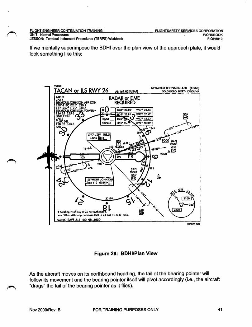
FLIGHT ENGINEER CONTINUATION TRAINING FLIGHTSAFETY SERVICES CORPORATION UNIT: Normal Procedures LESSON: Terminal Instrument Procedures (TERPS) Workbook
WORKBOOK FIQH5010
If we mentally superimpose the BOHi over the plan view of the approach plate, it would look something like this:
99028
TACAN or ILS RWY 26 AL-169.02 SEYMOUR JOHNSON AFB (KGSB)
GOlDSBORO, NORTH CAROUNA
~
c;\'~~
A 485
o~ .,,,, t Circling N of Rwy 8·26 not authoriz~ ~ ~, •• • When ALS lnop, increase RVR to 2-' ond Vil lo~ mile. '\.
EMERG SAFE Al T 100 NM .4000
Figure 29: BOHi/Pian View
390023.001
As the aircraft moves on its northbound heading, the tail of the bearing pointer will follow its movement and the bearing pointer itself will pivot accordingly (i.e., the aircraft "drags" the tail of the bearing pointer as it flies).
Nov 2000/Rev. B FOR TRAINING PURPOSES ONLY 41

FLIGHTSAFETY SERVICES CORPORATION FLIGHT ENGINEER CONTINUATION TRAINING WORKBOOK FIQH5010
Radial vs. Course
UNIT: Nonnal Procedures LESSON: Terminal Instrument Procedures (TERPS) Workbook
A radial is a magnetic bearing extending out from a VORNORTAC/TACAN navigation facility. Previously we used the BDHI bearing pointer pivot as the station, or navigation facility, when determining a general position relative to a selected NAVAID. The compass card portion of the BDHI then, is a representation of these radials, or magnetic bearing, from the NAVAID. Since we used the tail of the BDHI bearing pointer to determine our position in relation to the NAVAID, we can say that the tail of the bearing pointer tells us which radial the aircraft is on {Fig. 30).
NAVAID 000°
27rr @(r(r6 ~JI~ ~\.'-'~ )))~
FROM (RADIAL AND COURSE ARE THE SAME)
_:{ 21m
180° RADIALS
(TOP VIEW)
(SIDE VIEW)
Figure 30: Radial
TO (RADIAL AND COURSE ARE RECIPROCAL)
'!...T 0900
991-007.cdr
When selecting a desired course to be flown, the pilot must first determine if the course ,~ will take the aircraft TO or FROM the selected NAVAID {Fig. 30).
42 FOR TRAINING PURPOSES ONLY Nov 2000/Rev. B
., I

~
FLIGHT ENGINEER CONTINUATION TRAINING FLIGHTSAFETY SERVICES CORPORATION UNIT: Normal Procedures LESSON: Terminal Instrument Procedures (TERPS) Workbook
WORKBOOK FIQH5010
If the direction of flight (heading) is to be away FROM the station, the NAVAID radial will be the same value as the NAVAID course. In the example in Figure 31, the aircraft is heading 360° (due north). The tail of the bearing pointer is also on 360°, the aircraft heading. The head of the bearing pointer is on 180° on the BOHi compass card.
Therefore, the aircraft is flying away from the station on the 360° radial.
t 0
N
""'""'
270 \] 090
TAC AN 180
99f-006.cdr
Figure 31: BOHi Course
Since the tail of the bearing pointer and the magnetic heading are on the identical mark, the aircraft course is the same as the radial (360°). (No wind conditions.)
Nov 2000/Rev. B FOR TRAINING PURPOSES ONLY 43

FLIGHTSAFETY SERVICES CORPORATION FLIGHT ENGINEER CONTINUATION TRAINING WORKBOOK FIQH5010
UNIT: Normal Procedures LESSON: Terminal Instrument Procedures (TERPS) Workbook
In this second example (Fig. 32) the aircraft is heading 360°, due north. Now the head of the bearing pointer is also on 360° on the BOHi compass card. The tail of the bearing pointer is on 180°.
Therefore, the aircraft is flying to the station on the 180° radial.
t 0 N
270 090
180 991-0068.cdr
Figure 32: BOHi Course
When an aircraft is heading to the station, its inbound course is said to be the reciprocal of the radial its on. In our example, although we are on the 180° radial, the inbound course to the station is 360° (reciprocal of the 180° radial).
Adding or subtracting 180° from the radial that the aircraft is inbound on will result in the aircraft's course (i.e., 090° radial= 270° course, 330° radial= 150° course). Through the proper interpretation of radials, and inbound and outbound courses, you can keep yourself situationally aware in relation to an approach procedure. (19\,
44 FOR TRAINING PURPOSES ONLY Nov 2000/Rev. B

FLIGHT ENGINEER CONTINUATION TRAINING FLIGHTSAFETY SERVICES CORPORATION UNIT: Normal Procedures . WORKBOOK LESSON: Terminal Instrument Procedures (TERPS) Workbook FIQH5010
HORIZONTAL SITUATION INDICATOR (HSt)
The Horizontal Situation Indicator (HSI) Fig. 33, in most respects, is a combination of a heading indicator, radio magnetic indicator, course indicator, and range indicator. The combination of these indications are used for basic navigation and for determining the aircraft position in relation to a ground based radio navigation aid.
The HSI displays heading, desired course, course deviation, bearing, range, and direction of flight TO or FROM a navigation aid.
Imaginary •Lubber• Una
Course Arrow
Aircraft Heading -
99f-005.cdr
Figure 33: HSI
Can be determined by viewing the top center portion of the HSI. The HSI compass card is oriented to either magnetic or true north. The HSI in Fig. 33 shows the aircraft is on a heading of 025°.
Bearing Pointer -Shows the direction to a selected NAVAID based on aircraft heading. The pointer in Fig. 33 is about 038°, or 13° to the right of aircraft heading.
Course Arrow -The course arrow will point to the direction dialed up by the Course Set knob. The course will also be displayed in the Course Selector Window. Fig. 33 shows a desired course of 100°.
Nov 2000/Rev. B FOR TRAINING PURPOSES ONLY 45

FLIGHTSAFETY SERVICES CORPORATION FLIGHT ENGINEER CONTINUATION TRAINING WORKBOOK FIQH5010
UNIT: Normal Procedures LESSON: Terminal Instrument Procedures (TERPS) Workbook
46
.. - - ' .. ,
t-t-1---1 course Selector
Figure 34: HSI
Course Deviation Indicator (CDl)-
Window:···.
courstfdevfatlon .·1~a,1c~for(pDIF
99f-005a.ccf r
The CDI is similar to a steering bar and displays deviation from a selected course. The CDI will center up with the course arrow when the aircraft is on the selected course. If the steering bar is to the right of the course arrow the aircraft is left of course, and should steer right to the desired course. If the CDI is left of the course arrow, the aircraft is right of course and must steer left.
Course Deviation Scale -A series of dots perpendicular to the course arrow which show deviation left or right of the selected course. Each dot represents a specific number of degrees off course, depending on the type of approach flown.
Heading Marker -The heading marker is a movable index controlled by the Heading Set knob, and is used to visually aid the pilots in aligning the aircraft to a selected heading. As the aircraft turns, the HSI compass card will rotate with the heading marker. The pilot stops turning when the heading marker is at the 12 o'clock position.
Range Indicator -Will display distance to or from a TACAN station when TACAN is selected.
TO-FROM Indicator -A triangle shaped indicator that shows if the course selected, when intercepted, will take you to or away from a NAVAID (VOR, TACAN, VORTAC). If the indicator is pointing to the head of the course arrow, the selected course will take you to the NAVAID. If the indicator is pointing to the tail of the course arrow, the ~ selected course will take you away from the NAVAID. NOTE: The TO-FROM indicator is inoperative when flying an ILS or Localizer course.
FOR TRAINING PURPOSES ONLY Nov 2000/Rev. B

FLIGHT ENGINEER CONTINUATION TRAINING FLIGHTSAFETY SERVICES CORPORATION UNIT: Normal Procedures LESSON: Terminal Instrument Procedures (TERPS) Workbook
WORKBOOK FIQH5010
Exercise 2
Using the approach plate in Fig. S51md ttleinstrument indications in Fig. 36, answer the following questions pertaining to the aircraft position in relation to the navigational facility.
1. The aircraft is currently on a magnetic heading of ____ _
A. 140° B. 315° c. 135° D. 340°
2. The aircraft current position is indicated by which airplane symbol?
A. A B. B c. c D. D
3. Assuming the aircraft maintains ms current magnetic heading, it will be flying the station. ----
A. TO B. FROM C. Parallel D. Perpendicular
4. The aircraft is flying on the ___ .radial off the March Channel 77 (RIV).
A. 135 B. 315 c. 160 D. 340
Nov 2000/Rev. B FOR TRA1NING PURPOSES ONLY 47

FLIGHTSAFETY SERVICES CORPORATION FLIGHT ENGINEER CONTINUATION TRAINING WORKBOOK FIQH5010
UNIT: Nonnal Procedures LESSON: Tenninal Instrument Procedures (TERPS) Workbook
5. In this situation, the aircraft is positioned on the _____ course.
A. 315/inbound 8. 135/outbound C. 315/outbound D. 135/inbound
6. Where is/are the approximate location of the selected navigational aid?
A. 9 nautical miles away. 8. About 13° to the right of aircraft heading. C. On a course of 315°. D. Both A and B are correct.
7. Assuming the aircraft maintains its current heading, the black TQ-FROM indicator shows that it will be flying the station.
A. TO 8. FROM
48 FOR TRAINING PURPOSES ONLY Nov 2000/Rev. B
r-'\,

~ I I
FLIGHT ENGINEER CONTINUATION TRAINING FLIGHTSAFETY SERVICES CORPORATION UNIT: Nonnal Procedures LESSON: Tenninal Instrument Procedures (TERPS) Workbook
98309
ILS RWY 32 ATIS• 13"75 239.05 SOCAL APP CON 13"1.0 278.3 MARCH TOWER 127.65 253.5 GNDCON 125.0 335.8 CLNCDEL 125.0 335.8
. ~
CATEGORY S..ILS 32•
3220 .A
Al~.01 (USAF) MARCH FIELD (KRIV)
RIVERSIDE, CALIFORNIA
257A CAUTION: Ultralifabts •2799• and gllden in vjcinity
of Hemet-Ryan Arpt •
_,,,,-HEMET-RYAN ARPT • 3:w3
C D E 200 (200-l!i)
1760/40 264 (300-%
2140-1 % 2200-2 2660-3 (700-lo/. 662(7CJD.2) 1122(1200-3)
• When ALS lnop, Increase vis % mile. .. When ALS lnop Increase vis CAT AB·~ mlle,CAT COE ~ mile.
••• Orcllng not authorized NE of Rwy 1"4-32. Rapid rising terrain.
315• 6.2 NM from FM-
\LS RWY 32
Nov 2000/Rev. B
HIRl Rwy 14-32
Figure 35: Approach Plate
FOR TRAINING PURPOSES ONLY
FAF to MAP S.S NM 60 90 120 150 180
5:30 3:.CO 2:'5 2:12 1:50
RIVERSIDE, CALIFORNIA MARCH FIELD (KRIV)
390018.001
WORKBOOK FIQH5010
49

FLIGHTSAFETY SERVICES CORPORATION FLIGHT ENGINEER CONTINUATION TRAINING WORKBOOK FIQH5010
50
UNIT: Normal Procedures LESSON: Terminal Instrument Procedures (TERPS) Workbook
Figure 36: Instrument Indications e9c-ooa.oor
FOR TRAINING PURPOSES ONLY Nov 2000/Rev. B
/~

~ FLIGHT ENGINEER CONTINUATION TRAINING UNIT: Normal Procedures
FLIGHTSAFETY SERVICES CORPORATION - WORKBOOK
LESSON: Terminal Instrument Procedures (TERPS) Workbook FIQH5010
Exercise 2 Answer Key
1. B. 315°
2. c. c 3. A. TO
4. A. 135
5. A. 315/lnbound
6. A 9 nautical miles away
7. A. TO
Nov 2000/Rev. B FOR TRAINING PURPOSES ONLY 51

FLIGHTSAFETY SERVICES CORPORATION WORKBOOK FIQH5010
FLIGHT ENGINEER CONTINUATION TRAINING UNIT: Normal Procedures
LESSON: Terminal Instrument Procedures (TERPS) Workbook
NOTES
52 FOR TRAINING PURPOSES ONLY Nov 2000/Rev. B

FLIGHT ENGINEER CONTINUATION TRAINING FLIGHTSAFETY SERVICES CORPORATION UNIT: Normal Procedures LESSON: Terminal Instrument Procedures (TERPS) Workbook
WORKBOOK FIQH5010
CHAPTER 3: DEPARTURE AND TERMINAL ARRIVAL
DEPARTURE
Standard Instrument Departure
If the climbout procedure to be used is a Standard Instrument Departure (SID), the routing will be depicted on a plate very similar to an Instrument Approach plan view. A text of the Departure Route Description is also published on the plate. Refer to the departure plate, Fig. 37.
Assuming a takeoff from runway 32, the routing involves an initial left turn to track 155°, which puts the aircraft on an intercept heading to the 130° radial (130° course FROM the Paradise VORTAC). At 41 DME from the Paradise VORTAC, on the 130° radial, the aircraft will be at the SKYES intersection. Usually, clearance for a SID will also include TRANSITION routing. The depicted departure has three published TRANSITIONS: THERMAL, OCEANSIDE, and JULIAN. If, for instance, the pilot was cleared for the depicted departure, THERMAL TRANSITION, the departure routing
~ would include a left turn off the 130° course from Paradise to intercept the 057° course, (R-237) to Thermal VORTAC.
Once you have found your SID, compare it with the approach chart and departure procedures for your airfield. There may be obstructions on the approach plate which may not be so apparent on the SID and vice-versa.
Nov 2000/Rev. B FOR TRAINING PURPOSES ONLY 53

FLIGHTSAFETY SERVICES CORPORATION FLIGHT ENGINEER CONTINUATION TRAINING WORKBOOK FIQH5010
54
UNIT: Normal Procedures LESSON: Terminal Instrument Procedures (TERPS) Workbook
98365 SKYES-SEVEN DEPARTURE (SKYES 7•SKYES)
MARCH FIELD RIVERSIDE, CALIFORNIA
ATIS• 180 2"40 300 360
13 ... 75 239.05 CLNCDEL 125.0 335.8 GNDCON 125.0 335.8 TOWER
660 880 1100 1320 Minlmv.m Climb Rate to PDZ R-130/22 NM or passing 6000.
127 .65 253.5 SOCAL DEP CON 13'.0 278.3 MARCH RADAR 133.5 32-t.1
RADAR REQUIRED RWY 32 ONLY
LOS ANGELES CENTER 132.5 28U 4000
MA~~. RIV ::.-
·Chan77
RADAR REQUIRED FOR TRM TRANS
THERMAL 'P-:1.~ TANSITION tJ
CAUTION: During VMC cross ~ ;p • ~ dee end of rwv at ti.) :..i "'
or lw3000. /Jb~~o '"'", 0;10 JULIAN
OCEANSIDE ~-~~ 11 ... 0JllfFr."---- ... O'J ~ Chan87
115.30CN ::-· ~ l2 ~ -~6140 N33o ."3 ~:~ .. ~: q;o :..:.L:..:..:;~ SK"Yir-R·237 • W116°35.16'
W117°25.06'~ #-~~\. L-3 l·3. H-2 ~" ~ ~ 10J~ (j) 6.2 NM from Rwy 32
OCEANSIDE ~260° , · JULIAN N33021.co TRANSITION ~ '-R-OSO TRANSITION SKYES w111000.72'
DEPARTURE ROUTE DESCRIPTION
TAKE-OFF RWY 14: Climb direct HOF then via R-136 to PDZ R-113/or climb via RIV R-136 to20DME. Then turn right track 162. direct SKYES. Cross SKYES at or above 12,000. Thence via (transition) or assigned route.
TAKE-OFF RWY 32: Climb on runway heading, turn left crossing PDZ R-075/RIV 1 DME to track 155, cross PDZ R-075 southbound at or below 4000'. Proceed no closer than 7.5 DME PDZ/remain within 5 DME RIV. Intercept PDZ R-130 to SKYES, cross PDZ R-130/25 at or above 6000 ~ SKYES at or above 12,000. Thence via __ (transition) or assigned route.
JULIAN TRANSITION(SKYES 7•JLI): JLI R-283 JLI.
OCEANSIDE TRANSITION (SKYES 7•0CN): Via SKYES and PDZ R-130/51 DME intercept OCN R-080 to OCN.
THERMAL TRANSITION (SKYES 7•TRM): TRM R-237 to TRM.
SKYES .. SEVEN DEPARTURE (SKYES7•SKYES) MARCH FIELD 390024.001
Figure 37: SID
FOR TRAINING PURPOSES ONLY Nov 2000/Rev. B

FLIGHT ENGINEER CONTINUATION TRAINING FLIGHTSAFETY SERVICES CORPORATION UNIT: Normal Procedures . WORKBOOK LESSON: Terminal Instrument Procedures (TERPS) Workbook FIQH5010
Departure Planning
When departing from any airfield, pilots, navigators, and flight engineers must ensure they have exhausted all possible sources of information regarding obstacles that may exist in the departure area.
Told data computations are often started by the engineers well before the pilots show at the aircraft. The following sources will provide departure planning and obstacle information:
HQ AMC Airlift Suitability and Restrictions Report (ASRR) Flight Information Publications (FLIP) Enroute supplement Flight Information Publications (FLIP) Terminal (High or Low Altitude) Base Operations Other sources of information
HQ AMC Airfield Suitability and Restrictions Report (ASRR) -A quarterly publication identifying potential airfield problems, airfield operating procedures, and restrictions to help promote a safe operating environment.
~ Typically, TOLD information concerning obstacles may be found under paragraph (d.) titled "Additional Information", sub-paragraph labeled "Obstacle Data". Obstacle heights and distance information are presented in chart form for airfields having obstacle data.
FLIP Enroute Supplement -A DoD publication that contains general airfield information, flight data and procedures, and related aeronautical information for a specified location. Each listed airport contains runway information, communications, remarks, NAVAIDS, and ILS/Radar.
FLIP Terminal (High or Low Altitude)-A world-wide regional set of DoD publications that depict airfield diagrams, instrument approaches, and departure procedures. Other specific information included are obstacle height and distance, minimum climb rates, ATC climb rates, and ATC altitude restrictions.
Base Operations -Provides aircrews with the necessary information for safely planning all arrivals and departures. The following services should be used to assist pilots, navigators, and engineers with departures and obstacle data.
Notices To Airmen (NOTAMS) or Air Advisories (AIRADs) provide a computerized and regularly updated information service concerning specific airfield hazards or procedures not listed elsewhere.
Terrain charts for verifying obstacle and minimum climb rate computations. Chart Updating Manual (CHUM) is used to post changes to the terrain charts.
Nov 2000/Rev. B FOR TRAINING PURPOSES ONLY 55

FLIGHTSAFETY SERVICES CORPORATION FLIGHT ENGINEER CONTINUATION TRAINING WORKBOOK FIQH5010
UNIT: Nonnal Procedures LESSON: Terminal Instrument Procedures (TERPS) Workbook
Other Sources -Additional airfield information can be obtained from still a few other sources.
56
FAA Flight Service Station. Can be reached in the CONUS by dialing 1-800-WX-BRI EF. NOT AMS and a wide variety of weather forecasts are available.
The last source is the crewmembers visual inspection of the planned departure area. Obstacles such as ships in a harbor, or a newly erected structure off the end of the runway may not be depicted in other sources.
FOR TRAINING PURPOSES ONLY Nov 2000/Rev. B

FLIGHT ENGINEER CONTINUATION TRAINING FLIGHTSAFETY SERVICES CORPORATION UNIT: Normal Procedures . WORKBOOK LESSON: Terminal Instrument Procedures (TERPS) Workbook FIQH5010
TERMINAL ARRIVAL
Feeder Facilities/Published Routings
On approach plates, routings are provided from enroute or feeder facilities from the enroute structure to the Initial Approach Fix (IAF) but may take the aircraft to a point other than the IAF if operational circumstances require. The fix or point is sometimes identified by the radial and distance from a specified NAVAID. In the case of feeder facilities, the point-to-point has been computed for the pilot so that simply proceeding along the depicted radial (Course from the NAVAID), for the depicted distance, the aircraft will arrive over the desired fix, or point.
From the previous block of discussion we learned to determine a position from the HSI, BOHi, and OME presentations. When the aircraft is established on a feeder course, you can use the HSI, BOHi, and OME to monitor the aircraft position as it proceeds to the desired fix. Remember that the tail of the bearing pointer is the aircraft position FROM the NAVAID. When you read the number under the tail of the bearing pointer, you are reading the present radial from the facility. When the aircraft is established on course outbound from the station, this radial should be very nearly the same as the aircraft heading.
FEEDER FACILITY
Nov 2000/Rev. B
Figure 38: Feeder Facilities
FOR TRAINING PURPOSES ONLY
390025.001
57

FLIGHTSAFETY SERVICES CORPORATION FLIGHT ENGINEER CONTINUATION TRAINING WORKBOOK FIQH5010
UNIT: Normal Procedures LESSON: Terminal Instrument Procedures (TERPS) Workbook
Standard Terminal Arrivals (STARS}
Standard Terminal Arrivals (STARS) provide transition from the enroute structure to an outer fix, Initial Approach Fix, or arrival waypoint in the terminal area. A STAR will normally have a common reference point from which the arrival procedure originates.
Altitudes associated with STAR routing should be treated as minimum enroute altitudes. CONUS STARS are contained in a DoD FLIP document that includes departure and profile descent procedures along with STAR information.
58
98057 ST-369 [FAA,
CENTERPOINT ONE ARRIVAL CSl.CSll SAN ANTONIO APP CON 12.5.1307.0(Rwya 12hnd21)
~~ =~~rlsT 3 and 30) 273.5 RANDOLPHAFllATIS* . 271.8 SAN ANTONIO INTlATIS 118.9 STINSON MUNI ATIS* 128.1
NOTE: Choft "°'to Kale
N30•35.81'-W99•A9.05 l-15,M
SAN ANTONIO, TEXAS
FORT STOCKTON TRANSITION (fST.CSll): From ovor FST VORTAC via FST R·096 and CSI R-280 to CSI VORTAC. Thonco •••• JUNCTION TRANSmON (JCT.CSll): From ovor JCT VORTAC via JCT R· 134 and CSI R·314 to CSI VORTAC. Thence •••• • • • • From ovor CSI VORTAC via CSI R· 105 to REUBE INT. Expect vector to final approach courso. SATELLITE AIRPORTS: Conform to SAT routing and frequency assignment.
CENTERPOINT ONE ARRIVAL (CSl.CSll) 9IOR
Figure 39: STAR
SAN ANTONIO, TEXAS 390026.001
FOR TRAINING PURPOSES ONLY Nov 2000/Rev. B

FLIGHT ENGINEER CONTINUATION TRAINING FLIGHTSAFETY SERVICES CORPORATION UNIT: Normal Procedures . WORKBOOK LESSON: Terminal Instrument Procedures (TERPS) Workbook FIQH5010
Exercise 3
Use the departure plate in Fig. 40 to answer the following questions pertaining to a Standard Instrument Departure.
1. The departure for runway 32 requires a left turn upon crossing the
A. Paradise VORTAC Radial 075/RIV I DME. B. Paradise VORTAC Radial 133. C. Paradise VORTAC Radial 130/RIV 5 DME. D. Paradise VORTAC Radial 130/RIV 25 DME.
2. Once the left turn is completed, you must cross the same radial southbound at an altitude at or below feet.
A. 3,000 ft B. 4,000 ft c. 5,000 ft D. 12,000 ft
3. When crossing the Paradise Radial 130/25 you should be at or above
A. 3,000 ft B. 4,000 ft c. 6,000 ft D. 12,000 ft
4. Passing the SKYES intersection, what is the mag course for the THERMAL TRANSITION?
A. 057 B. 130 c. 021 D. 075
Nov 2000/Rev. B FOR TRAINING PURPOSES ONLY 59

FLIGHTSAFETY SERVICES CORPORATION FLIGHT ENGINEER CONTINUATION TRAINING WORKBOOK FIQH5010
60
UNIT: Normal Procedures LESSON: Terminal lnstrum~nt Procedures (TERPS) Workbook
98365
SKYES-SEVEN DEPARTURE (SKYES 7•SKYES) ATIS•
MARCH FIELD RIVERSIDE, CALIFORNIA
180 240 300 360 660 880 uoo 1320 l:M.75 239.05
ONCDEL 125.0 335.8 GNDCON
Minimum Climb Rate to PDZ R-130/22 NM or passing 6000.
125.0 335.8 TOWER 127.65 253.5 SOCAL DEP CON 13..0 278.3 MARCH RADAR 133.5 324.1
RADAR REQUIRED RWY 32 ONLY
LOS ANGELES CENTER MARCH 132.5 28U 4000 RIV ::;;_
\ Chann '-~~+-~~~"--~~~~~-R-075____.
CAUTION: During VMC cro11 depend of rwy ot orblw3000.
HOMELAND 113.4 HOF nll.
RADAR REQUIRED FOR TRM TRANS
DEPARTURE ROUTE DESCRIPTION
SKYES N33°21.40 w111°00. 12 •
TAKE-OFF RWY 14: Climb direct HOF then via R-136 to PDZ R-113/or climb via RIV R-136 to200ME. Then turn right track 162. direct SKYES. Cross SKYES at or above 12,000. Thence via (transition) or assigned route.
TAKE-OFF RWY 32: Climb on runway heading, turn left crossing PDZ R-075/RIV 1 DME to track 155, cross PDZ R-075 southbound at or below 4000'. Proceed no closer than 7.5 DME PDZ/remaln within 5 OME RIV. Intercept PDZ R-130 to SKYES, cross PDZ R· 130/25 at or above 6000: SKYES at or above 12,000. Thence via __ (transition) or assigned route.
JULIAN TRANSITION(SKYES 7•JLI): JLI R-283 JLI.
OCEANSIDE TRANSITION (SKYES 7•0CN): Via SKYES and PDZ R· 130/51 DME intercept OCN R-080 to OCN.
THERMAL TRANSITION (SKYES 7•TRM): TRM R-237 to TRM.
SKYES-SEVEN DEPARTURE {SKYES7•SKYES)
Figure 40: SID
FOR TRAINING PURPOSES ONLY
MARCH FIELD 390024.001
Nov 2000/Rev. B
.~

FLIGHT ENGINEER CONTINUATION TRAINING FLIGHTSAFETY SERVICES CORPORATION UNIT: Normal Procedures LESSON: Terminal Instrument Procedures (TERPS) Workbook
WORKBOOK FIQH5010
Use Fig. 41 to answer the following questions.
5. Approaching Altus AFB from the Wichita Falls VORTAC to intercept the Altus IAF (OKKIE), what is the outbound radial from the feeder facility?
A. R-352 B. R-301 C. R-173 D. R-072
6. What is the recommended altitude outbound from the Childress VORTAC to the Altus AFB IAF (OKKIE)?
A. 3,300 ft B. 3,600 ft c. 4,900 ft D. 4,000 ft
7. What is the intercept distance from the Hobart VORT AC to the Altus AFB IAF (OKKIE)?
A. 45 NM B. 25 NM C. 51 NM D. 36 NM
8. What is the radial outbound from Altus AFB to the MARTHA holding fix?
A. R-171 B. R-173 C. R-351 D. R-353
9. The altitudes associated with the ILS RWY 35 are considered
A. Minimum Altitudes B. Maximum Altitudes C. Mandatory Altitudes D. Recommended Altitudes
Nov 2000/Rev. B FOR TRAINING PURPOSES ONLY 61

FLIGHTSAFETY SERVICES CORPORATION FLIGHT ENGINEER CONTINUATION TRAINING WORKBOOK FIQH5010
62
UNIT: Normal Procedures LESSON: Terminal Instrument Procedures (TERPS) Workbook
00055 ALTUS AFB (KL TS) ILS RWY 35L AL-482. (USAF) AL lUS, OKLAHOMA
ATIS• 273.5 FORT WORTH CENTER 128.4 290.2 ALTUS APP CON 125.1 348.3 ALTUS TOWER 119.65 255.8 GNDCON 121.85 275.8 CLNCDEL 120.65 316.9 ASR/PAR
ALTUS 1J2&Jl LTS ;:;::"
Chan35
LTS t Ii§> ~,,,,,, '4-R-351
l :: Max holding 230 KIAS :0 ~MATHA
~ j_~ ~,,,,u,\\'
r...1792
LOCALIZER J.l2J l·LTS :_:. ••
r... 2180
1394
r...1720 DME OR RADAR REQUIRED
(IAF) OKKI
LTS Hi)
bl Cf)
LTS
ID /RADAR
Max holding airspeed 230 KIAS
EMERG SAFE ALT 100 NM 4800
OKKIE R-173 ~ [ID L§..1
.. 173• 1.. ~AR 353•-. T~;:% ~?45 3000 3000 I '•·'· .,
-12eoo 1 ,-GS2.50° 1 I TCHs1 I l
8-ILS 35L"
8-LOC 35L"" 1660/24
307 30QJ'2
MISSED APPROACH Cl!mb to 4000 OUT
LTSR·351 to MATHA and hold.
'¥> 11']) VORTAC 1.i,-1 I
I ,.~
''•'·'~' .. '''''''\'
1660/40 307 (~4)
CIRCLING-1760-1 1840-1 1840-11/2 1940-2 1980-2
378 (400-1) 458 (500-1) 458 (S00-1'" 558 (600-2) 59 600-2)
ELEV 1382
1553124 200 (200-'") GS 2.5° HIRL Rwy 17R-35L. t-.-Whe-n_AL_S.._lno_p_, _lnete_ase_R_VR_t_o 40~and-vls_t_df._4 -m-lle..;.. _....;....__;;...;...;;.;.;__ __ -I 17L-35R, 352• 5.0 NM s-PAR 35L
•• When ALS lnop, Increase RVR to 50 and vis to 1 mile. MIRL Assault Stri from FAF •••Circling not authorized W of Rwy 17R-325L. FAF to MAP 4.5 NM
ILS RWY 35L
Knots 80 90 120 150 180 Mln:Sec 4:30 3:00 2:15 1:48 1:30
34° 40'N-99°18W
Figure 41: Approach Plate
FOR TRAINING PURPOSES ONLY
AL lUS, OKLAHOMA ALTUS AFB (Kl TS)
390027.001
Nov 2000/Rev. B

~
FLIGHT ENGINEER CONTINUATION TRAINING UNIT: Normal Procedures LESSON: Terminal Instrument Procedures (TERPS) Workbook
Exercise 3 Answer Key
Part 1
1.
2.
3.
4.
Part2
5.
6.
7.
8.
9.
A.
B.
c. A.
B.
A.
B.
D.
A.
Paradise VORTAC Radial 075/RIV 1 DME
4,000 ft
6,000 ft
057
R-301
3,300 ft
25NM
353°
Minimum Altitudes
FLIGHTSAFETY SERVICES CORPORATION . WORKBOOK
FIQH5010
Nov 2000/Rev. B FOR TRAINING PURPOSES ONLY 63

FLIGHTSAFETY SERVICES CORPORATION WORKBOOK FIQH5010
FLIGHT ENGINEER CONTINUATION TRAINING UNIT: Normal Procedures
LESSON: Terminal Instrument Procedures (TERPS) Workbook
NOTES
64 FOR TRAINING PURPOSES ONLY Nov 2000/Rev. B

FLIGHT ENGINEER CONTINUATION TRAINING FLIGHTSAFETY SERVICES CORPORATION UNIT: Normal Procedures . WORKBOOK LESSON: Terminal Instrument Procedures (TERPS) Workbook FIQH5010
CHAPTER 4: INSTRUMENT APPROACHES
Approaching the destination, the pilot will choose an appropriate instrument procedure for the descent and landing.
A Radar Approach consists of radar monitoring and vectors to a final landing. Radar vectors to final consist of being given magnetic headings to fly to a point where vectoring is discontinued. The aircraft is then expected to continue on its own guidance and instruments to a final landing.
NOTE: The BOHi always displays magnetic heading. The HSI displays true heading when INS is selected {True or Magnetic on FMS/GPS equipped aircraft) and magnetic when TACAN or VOR are selected. Be sure you are looking at magnetic and NOT true headings when being radar vectored.
Without radar monitoring or vectors, the pilot can, with the appropriate navigation equipment, complete an entire approach as published in the approach plate booklet. There are some exceptions to this as when an approach procedure states RADAR REQUIRED in the plan view.
TACANRWY 23 POPE AFB (KPOB) AL-147.03 (USAF) FAYmEVILLE, NORTH CAROLINA
390028.002
Figure 42: Instrument Approaches
Nov 2000/Rev. B FOR TRAINING PURPOSES ONLY 65

FLIGHTSAFETY SERVICES CORPORATION FLIGHT ENGINEER CONTINUATION TRAINING WORKBOOK FIQH5010
UNIT: Normal Procedures LESSON: Terminal Instrument Procedures (TERPS) Workbook
Approach plates are contained in two separate booklets; High Altitude and Low Altitude.
High Altitude Books -Distinguished by the black and white hash marks on the booklet's cover, back and spine, and cover region (i.e., Southwest, Northeast). High altitude books also contain the military SIDs for each area. This type of approach is called a penetration. They are not commonly flown, but can be used to land at a given field.
66
DOD FLIGHT INFORMATION PUBLICATION
(TERMINAL)
HIGH ALTITUDE UNITED STATES· AIRPORT DIAGRAMS
INSTRUMENT APPROACH PROCEDURES MILITARY DEPARTURE PROCEDURES
RADAR INSTRUMENT APPROACH MINIMUMS
EFFECTIVE 25 FEB 99 TO 22 APR 99
Figure 43: High Altitude FLIP
FOR TRAINING PURPOSES ONLY
390029.001
Nov 2000/Rev. B
~ ' '

FLIGHT ENGINEER CONTINUATION TRAINING FLIGHTSAFETY SERVICES CORPORATION UNIT: Normal Procedures LESSON: Terminal Instrument Procedures (TERPS) Workbook
Low Altitude Books -Cover groupings of states {CONUS); can also include airfield SIDs.
DOD VOL-6 FLIGHT INFORMATION PUBLICATION
(TERMINAL)
LOW ALTITUDE UNITED STATES AIRPORT DIAGRAMS
-INSTRUMENT APPROACH PROCEDURES MILITARY DEPARTURE PROCEDURES
RADAR INSTRUMENT APPROACH MINIMUMS
EFFECTIVE 28 JAN 99 TO 25 MAR 99
TCN EFFECTIVE 25 FEB 99
Consult NOTAMS for latest information
PUBLISHED IN ACCORDANCE WITH INTER-AGENCY AIR CARTOGRAPHIC COMMITTEE SPECIFICATIONS AND AGREEMENTS APPROVED BY
Figure 44: Low Altitude FLIP
390030.001
WORKBOOK FIQH5010
Contained within approach booklets are the different types of procedures to get an ~ aircraft to the landing runway. What follows are a very basic list and descriptions of the
various types of instrument approaches contained in their respective booklets.
Nov 2000/Rev. B FOR TRAINING PURPOSES ONLY 67

FLIGHTSAFETY SERVICES CORPORATION FLIGHT ENGINEER CONTINUATION TRAINING WORKBOOK FIQH5010
UNIT: Normal Procedures LESSON: Terminal Instrument Procedures (TERPS) Workbook
High Penetrations -Contained within the High Altitude Book. Enables an aircraft to transition from the high altitude structure to a position on and aligned with an inbound course to the Final Approach Fix. These approaches can employ radials, arcs, courses, turns, fly-off restrictions, etc
68
"'"'"'"'"'"'~"'~"'~~"'~~~~
StarttumatFL100 ,4•.314'••••• NOB remain w!lhln ••••••• FL 160 22NM. .••
: FL 100
••• k. ...... ......... ;·,·,··:~,'.:·.:-:.·,.·:·.'.. . . .. .,,r .1••''""" 1600 l"/;;)'!~·J'.f4e.~ .. UKK2 0'•J;:,;, ,,:~ MM
GS2.75" '" . "TCH57
CATEGORY 11 .
S-NDB 11•
CIRCLING
S-PAR 11"
c
TA 7000 MISSED APPROACH
Climb to 1500, then
d=b:t~~tg~ ~3:t.
KEFLAVIK NAS (BIKF) KEA.AW<. IC:ELAND
LT ~
.;95 RT
HI NDB Or ILS RWY 11 63'59'N·22°36'W KEFLAVIK,ICELAND • KEFLAVIK NAS (BIKF)
"'"' ~ "'"' "'"'"' "'"'"'"'~"'"'ii Figure 45: High Penetration
FOR TRAINING PURPOSES ONLY Nov 2000/Rev. B

f""--1 FLIGHT ENGINEER CONTINUATION TRAINING FLIGHTSAFETY SERVICES CORPORATION UNIT: Normal Procedures LESSON: Terminal Instrument Procedures (TERPS) Workbook
Procedure Turns -
WORKBOOK FIQH5010
Depicted in the plan view with a barb ( ____/ ); the barb indicates the maneuvering side of the final approach course.
And5A98337
r-:N=D~B~R:":""WY __ 3_5_R ____ ~AL-t tFMJ ATIS 118.25 ABllfNE /IJIP CON 125.0 338.3 (EAST) 121.2 282.3 CWESO ABILENE TOWER 120.1 257.8 GNDCON
ABILENE REGIONAL CABI) ABnfNE, TEXAS
121.7 348.6 ASR
ABILENE lll.Z ABI :.-: • •
<la'l 8' ..
nJSCOIA .ll.U. TQA ;:_-·
Chan 53
MISSED APPROACH Oimb lo 3300 via AB bearing 352° lo 5ml Int and hold.
CATEGORY
R.07\
S·35R 2320-~ 545 (600-U)
CIRCUNG 2320-1 530 (600-1)
NDBRWY35R Amcft SA 98337
c 2320-1
545(600·1
D
2360·1~ 570 600-1~
2320·1~ 545 600-1~
2360-2 570(600-2 · TDZE
$l 1775 HIRL 1!wY 17l·35R 3SR 3520 M!Rl~4-22 and 17R·3St 5.4 NM REIL Rwy 3Sl from FAF
Knots 60 90 120 150 180 ·n: 5:24 3:36 2:42 2:10 1:48
32°25' N • 99°41'W ABILENE, TEXAS 1 ABILENE REGIONAL (ABI)
Figure 46: Procedure Turns 390032•01
Nov 2000/Rev. B FOR TRAINING PURPOSES ONLY
PROCEDURE TURN
69

FLIGHTSAFETY SERVICES CORPORATION FLIGHT ENGINEER CONTINUATION TRAINING UNIT: Normal Procedures
LESSON: Terminal Instrument Procedures (TERPS) Workbook WORKBOOK FIQH5010
Holding Patterns (in Lieu of Procedure Turn) -Depicted as a heavy line in the plan view; descent is usually accomplished in the specified holding pattern.
70
97310
VOR or VOR/DME or TACAN2RWY1 AL·562.0.C (USAF)
ATIS* 135.05 773.5 DOVER 1'J'P CON 128.0 339.l DOVER TOWER 126.35 327.5 GND CON 121.9 225.• CLNC DEl 125.SS 289.• ASR
fJ. 2S.
lo tv. ~
**RADAR REQUIRED •••When AlS lnop , lnueoH vl1 1/1 mile.
IM
••••When AlS lnof. , lncreoH vi• CA.T ABE 'h , CAT CO I/, ml e.
EMERG SAFE Al T 100 NM 4400 FROM "ENO" VORTAC
MISSED /'J'PROACH Climbing right turn to 1700 via "ENO' R-171
to BAREW/ 1• DME and
BAREW [ill Holding pottorn
hold I 171 °~
_.,..,.~ ~ 3510 1700 ,..,,,,.,,. · 1'
~., ~ "~ ... .............
CATEGORY
S-VOR 1 ::.
A a .CB0/2.C
453 (50(). '11 )
S·VOR/ .C00/ 2.C 373 (..00. 'h l OME 1•••
I I
c .CBO/ .CO
453(500-%
.400/ .CO
0 E
.CB0/ 50 453 (500-1)
373 ("400-% l
DOVER AFB (KDOV) DOVER, DELAWARE
ELEV 30 Rwy 14 ldg 8652'
133• I 183 " *~ .;;; ..
351 • 6.7 NM l 'TOZE <9' From BAREW I ~ 27
EN014DME dJ
1-----+------:----+-----.--37l----r(--'OO-_Y._•l--l TOZL Rwy 1 "-.. ~ I REil Rwy 32 ~
500 1 500· 1 V1 600·2 620·2 HIRl R 1 19 U 32
S-TAC 1••• .C00/ 2"' 373 (-'00- '6) .COOi.CO
• 470 (50(). l) 470 (50(). l'h 570 (600-2) 590 (600-2) l----wy-'--·-· -·---..l..----1 FAF to MAP-6.7°NM
CIRCllNG•
VOR or VOR/DME or TACAN2RWY 1
39'08'N-75'28'W
Figure 47: Holding Pattern
FOR TRAINING PURPOSES ONLY
DOVER, DELAWARE DOVER AFB (KOOV)
390033.001
Nov 2000/Rev. B

FLIGHT ENGINEER CONTINUATION TRAINING FLIGHTSAFETY SERVICES CORPORATION UNIT: Nonnal Procedures . WORKBOOK LESSON: Tennlnal Instrument Procedures (TERPS) Workbook FIQH5010
Procedure Tracks -Similar to the Penetration, it may use any combination of arc, radials, etc to align the aircraft with final approach. Procedure tracks are shown as a heavy line with directional arrows.
TACANRWY23 ATIS POB-- -132.3 :M9.7 IT1' FAYmMLLE APP CON \. rY t.:.:I 2710.()900 119.55393.0 \ .. '~... ~ ' 091°.2100 133.0 295.y .,,. 'f>.~ ' POPE TOWER vv-135.025 291.1 / GNDCON 124.ss 21s.e I CLNCDEl. I 275.8
I f
I \
fft' -·~ itJt
IAF \ BEN TN
JI J
POPE \ R·5311 A,8,C
\ \
Chan 85 POB :.-? I I
RADAR REQUIRED
" CAUTION:Avold R·5311 A,B,C located 2.5 DME·west offleld. '-.
EMERG SAFE ALT 100 NM 5100 MISSED APPROACH
lmmedlote cUmblng right tum to Intercept R-330 to 2000,
to AWGUS and hold.
~ TACAN ID I
I I
"--1 CATEGORY
s.23• 660140 460
CIRCLING•• 740· 1 522 (600-1)
D
A 949
660/50 460 S00.1
860-2 642(700-2)
*When ALS lnop, lncrea• vls CAT J.B ~ mile, CAT CD % mile. ••CAUTION: Clrcllng not authorized SE of Rwy 05-23. . v
TACANRWY23
E
A 1049
NA
NA
ELEV 218 Rwy 05·23 ldg 8501' by use of dep and overrun Rwy05-23tkot 8501' Incl NJ: or SW 222° to surface by back TACAN taxiing
FAYETTEVILLE, NORTH CAROLINA POPE AFB (KPOB)
390028.001
Nov 2000/Rev. B
Figure 48: Procedure Tracks
FOR TRAINING PURPOSES ONLY
PROCEDURE TRACK
71

FLIGHTSAFETY SERVICES CORPORATION WORKBOOK FIQH5010
Exercise 4
FLIGHT ENGINEER CONTINUATION TRAINING UNIT: Normal Procedures
LESSON: Terminal Instrument Procedures (TERPS) Workbook
Match the instrument approaches in Fig. 49 and 50 with their proper category/name listed below (example A. 2.)
1. Procedure Turn
2. Holding Pattern in Lieu of Procedure Turn
3. Procedure Track
4. High Penetration
A.
8.
c.
D.
72 FOR TRAINING PURPOSES ONLY Nov 2000/Rev. B
I~

FLIGHT ENGINEER CONTINUATION TRAINING FLIGHTSAFETY SERVICES CORPORATION UNIT: Normal Procedures LESSON: Terminal Instrument Procedures (TERPS) Workbook
A.
B.
Nov 2000/Rev. B
98141
ILS 1 RWY 24 AL·l50.04 (USAF) MC GUIRE AFB (KWRI)
WRIGHTSTOWN NEW JERS1:Y
~~ 270.1 ,,,....... -£iijiciUif'"FACiliiifs --
MC GUIRE APP CON / RO!&INSVILL0 °" =.::,~;xu• C 1~:n~v ,
091°·2690 "GXU" /yARDlEV
~~2:~0WER/ ':!Aft° 118.65 255.6 GNDCON I 121.8 275.8 QNCDa, 135.2 335.8
I I \
If radar Inoperative, expect 15 min deloy for deactlYOtlon of R·SOOI.
EMERG SAFE ALT 100 NM ........... --5000 FROM "GXU" VORTAC - - __.
,..M, ..... LOC BC RWY 22
Figure 49: Instrument Approaches
FOR TRAINING PURPOSES ONLY
390034.001
. WORKBOOK FIQH5010
73

FLIGHTSAFETY SERVICES CORPORATION FLIGHT ENGINEER CONTINUATION TRAINING UNIT: Normal Procedures
LESSON: Terminal Instrument Procedures (TERPS) Workbook WORKBOOK FIQH5010
c.
D.
74
9lt2S3
Hl-TACAN l RWY 27 CHICAGO CENl(lt 133.3 380.35 VOlK An CON
~~~T~h / 127.5 (ct"F)I 236.61 GNDCON 121.9 775.8 / "5R
I I
I
I NOOINt
'Q--001· -\ (II)
\ \
Amdtl 97310
ILS RWY 19 ATI$• 135.05 773.5
DOVEi - CON t21.0 339.1 DOVER TOWH / 126..l.S 327.s I GNO CON
121.9 ?2.S.A/ ONC DEL 12.S.!55 289."
ASll I
I I \ \ \
\
" ""-.
Al-~2.o3 (USAf)
A 15'9
- +- --..... ~ .
VOLK FIELD (VOK) C>HP llOUGUS, WISCONSIN
I
DOVER AF6 (KDOV) DOVER, DEV.W-
CEDAALME
.? ~~' \ ~ \
i \ \ I I
I
390042.001
Figure 50: Instrument Approaches
FOR TRAINING PURPOSES ONLY Nov 2000/Rev. B

FLIGHT ENGINEER CONTINUATION TRAINING FLIGHTSAFETY SERVICES CORPORATION UNIT: Normal Procedures . WORKBOOK LESSON: Terminal Instrument Procedures (TERPS) Workbook FIQH5010
Exercise 4 Answer Key
A. 3 (Procedure Track}
B. 1 (Procedure Turn}
C. 4 (High Penetration}
D. 2 (Holding Pattern In Lieu of Procedure Turn}
Nov 2000/Rev. B FOR TRAINING PURPOSES ONLY 75

FLIGHTSAFETY SERVICES CORPORATION WORKBOOK FIQH5010
FLIGHT ENGINEER CONTINUATION TRAINING UNIT: Normal Procedures
LESSON: Terminal Instrument Procedures (TERPS) Workbook
NOTES
76 FOR TRAINING PURPOSES ONLY Nov 2000/Rev. B

FLIGHT ENGINEER CONTINUATION TRAINING FLIGHTSAFETY SERVICES CORPORATION UNIT: Nonnal Procedures . WORKBOOK LESSON: Tenninal Instrument Procedures (TERPS) Workbook FIQH5010
CHAPTER 5: INITIAL APPROACH FIX TO FINAL APPROACH FIX
Initial Approach Fix (IAF)
Before the pilot can safely descend below specified altitudes, the aircraft must have clearance and/or be established on a published segment of the approach. The approach must obviously begin at some point, and continue·to either a successful landing or missed approach. One possible exception to this is when the pilot has been given vectors and clearance to intercept the final approach course and proceed with the approach. When the controller has issued a clearance to fly the full approach, the pilot must maneuver the. aircraft to begin the letdown from a designated starting point or Initial Approach Fix (IAF) in Fig. 51. IAFs are most often a named point defined as a radial and DME. However, the IAF could be a NAVAID. There may be more than one IAF available for an approach as illustrated below.
99028
TACAN or ILS RWY 26 AL-169.02 u SEYMOUR JOHNSON AFB (KGSBJ
GOU>SSORO, NORTH CAROllNA
ATIS* 273.5 SEYMOUR JOHNSON APP CON
fi~=~~:1liJ ~~u SEYMOUR JOKNSON TOWER* 126.25 255.6 GNDCON 275.8 ClNCDEL 128.02 363.8 PAR
RADARorDME REQUIRED
EEGEl N35• 29.80' W77• 23.56'
N35• 25.9 .. ' W77• 37.47' GS8 t-tBOl:-J --+-N3-5-. 0-6.9-,.-W77-.-.. 3-.33-I' HY) .._t_ACAN _ _._N3_s•_20_.10'_W77_•_se_.30_,' ~
'(IAFJA 12"9. r:.o7~./9-Jl7 ..,.,...,,.==~...,.. SNNOW ~ 1.S9
~ ').5~(1AF) EEG EL
ll-oa9- ~sa 202aA~
A 485
1' Circling N of Rwy 8·26 nol aulhorized. ••• Wh•n ALS lnop, increa•• RVR to 2 .. ond ¥i• to~ mil•.
EMERG SAFE ALT 1 CO NM 4000
390035.001
Figure 51. Initial Approach Fix
From this point on, the pilot is guaranteed adequate terrain and obstruction clearance as long as the aircraft is maneuvered on the depicted track and maintains depicted altitude restrictions.
Nov 2000/Rev. B FOR TRAINING PURPOSES ONLY 77

FLIGHTSAFETY SERVICES CORPORATION FLIGHT ENGINEER CONTINUATION TRAINING WORKBOOK FIQH5010
Descent Procedures
UNIT: Normal Procedures LESSON: Terminal Instrument Procedures (TERPS) Workbook
The pilot will brief the approach, including the altitude at which the aircraft will depart the IAF and, as appropriate, restrictions to the descent as the aircraft proceeds to the FAF. The entire crew should be particularly interested in these altitude restrictions because as the aircraft descends along the approach corridor, the crew may be going below the Emergency Safe and Minimum Safe Altitudes for the area. Failure to observe and comply with altitude restrictions or deviations off course could have serious consequences.
As you look at a variety of approaches you will note four different types of altitudes depicted. Looking at the legend in the front of the booklet, we see that the definitions for these altitude depictions are as follows:
Mandatory Altitude
Must be at This altitude
Minimum Altitude
ALTITUDES
4,800
Maximum Altitude
Do not Do not be Descend below above this
this altitude altitude
Figure 52: Altitudes
2,200
Recommended Altitude
Altitude best suited for this
approach
You may not recognize any of these altitude definitions from your pilot's briefing. This is because few pilots will use the terminology used in the legend. More commonly you will hear terms like "step down". "no lower than 2,300", no higher than 4,800", and "hard altitude 5,500".
The ideal situation for any instrument approach is to arrive at a position perfectly aligned with the final approach course with sufficient distance from the FAF for establishing proper configuration and stable speed. In today's radar controlled environment this apparently idyllic situation is actually the norm. Why then, do we need these intricate and confusing procedures for accomplishing an instrument letdown? The obvious reason is, for the time when radar service is not available or practical. The wide variety of letdown procedures all have points in common; they allow for safe descent from cruise altitude to approach altitude; they provide information about the airport environment to assist the pilot in transitioning from instrument to visual
78 FOR TRAINING PURPOSES ONLY Nov 2000/Rev. B
.~
I~

FLIGHT ENGINEER CONTINUATION TRAINING FLIGHTSAFETY SERVICES CORPORATION UNIT: Normal Procedures LESSON: Terminal Instrument Procedures (TERPS) Workbook
WORKBOOK FIQH5010
conditions; they provide instructions for returning to safe flying conditions if a landing cannot be made (missed approach). This portion of the course will specifically address the phase of the approach which begins at the IAF and ends at the FAF or glide slope intercept point.
Since any instrument approach considers three dimensions, we must also be aware of any specific altitude requirements associated with the IAF. Generally, altitude at the IAF will be minimum altitudes. Occasionally, you will see an approach with a Maximum or Mandatory altitude at the IAF. In any event, the pilot bears responsibility for adhering to any altitude restrictions and determining the suitability of an altitude for the approach to be flown. Refer to Fig. 53, the TACAN approach below. Note that the CELLA IAF has an associated altitude of 3,000 ft. This of course, means that the aircraft must be at or above 3,000 MSL before proceeding past the CELLA IAF inbound on the approach.
Once overhead CELLA, the aircraft can continue its descent to the next altitude restriction; this being at 2,000 feet at JODDY/6.5 DME.
98281
Nov 2000/Rev. B
TACAN RWY 15 Al-391.00 (USAF BARK~ciN.'tJfi&s:el A.TIS
EMERG SAFE All lOO NM 3200
R-332 CEl\tn . 3000~ JOODY -, l.s~. lill
I '._j I 2000• I -I I I
Figure 53: Altitude Depictions
FOR TRAINING PURPOSES ONLY
"' 288
390031.001A
79

FLIGHTSAFETY SERVICES CORPORATION FLIGHT ENGINEER CONTINUATION TRAINING WORKBOOK FIQH5010
UNIT: Nonnal Procedures LESSON: Tenninal Instrument Procedures (TERPS) Workbook
Exercise 5
Use the approach plate in Fig. 54 to answer the following questions:
1. The published altitude at the IAF (CELLA) for this approach is a
A. Maximum altitude B. Mandatory altitude C. Minimum altitude D. Recommended altitude
2. The published altitude at the Final Approach Fix (JODDY) is a
A. Maximum altitude B. Mandatory altitude C. Minimum altitude D. Recommended altitude
80 FOR TRAINING PURPOSES ONLY Nov 2000/Rev. B

FLIGHT ENGINEER CONTINUATION TRAINING FLIGHTSAFETY SERVICES CORPORATION UNIT: Normal Procedures LESSON: Terminal Instrument Procedures (TERPS) Workbook
98281
TACAN RWY 15
A lo.t9
EMERG SAFE Al T 100 NM 3200
R-332 15 . CE~ 3000 JODDY --1 l.S~o liJ)
I "-.i I -• I 2000 I -, I I
Al-391.03 (USAF)
Maximum Holding Airspeed 230 Knots
CATEGOiY A 8 E A
560/24 560 0 560/50 9 S.TAC 15• 39.C (.COO.%} . /4 39.C (.COO.%} 39.c (.COO..l)
ORO.ING.. 720-2 55.c (600-2)
S.ASR1s• .. 620/40 .cs.c (500-%) 620/50 .cs.c (500-t)
WORKBOOK FIQH5010
BARKSDALE AFB lKBAOl BOSSIER Cl1Y, LOUISIANA
A 288
1-----'-----------..a.-------1HIRLRwy15-33 -when ALS lnop, Increase vis CAT ABDE % mile, CAT C y, mlle •
Nov 2000/Rev. B
.. Clrcllng not authorized W of Rwy. Clrclfng not authorized over wops stor area E of arpt.
•••When ALS inop, increase vis all CAT % mile.
TACAN RWY 15
Figure 54: Approach Plate
FOR TRAINING PURPOSES ONLY
BOSSIER CITY, LOUISIANA
BARKSDALE AFB (KBAD) 390036.001
81

FLIGHTSAFETY SERVICES CORPORATION FLIGHT ENGINEER CONTINUATION TRAINING WORKBOOK FIQH5010
Exercise 5 Answer Key
1. c 2. 8
82
UNIT: Normal Procedures LESSON: Terminal Instrument Procedures (TERPS) Workbook
FOR TRAINING PURPOSES ONLY Nov 2000/Rev. B

FLIGHT ENGINEER CONTINUATION TRAINING UNIT: Normal Procedures LESSON: Terminal Instrument Procedures {TERPS) Workbook
NOTES
FLIGHTSAFETY SERVICES CORPORATION WORKBOOK
FIQH5010
Nov 2000/Rev. B FOR TRAINING PURPOSES ONLY 83

FLIGHTSAFETY SERVICES CORPORATION FLIGHT ENGINEER CONTINUATION TRAINING WORKBOOK FIQH5010
84
UNIT: Normal Procedures LESSON: Terminal Instrument Procedures (TERPS) Workbook
THIS PAGE INTENTIONALLY LEFT BLANK
FOR TRAINING PURPOSES ONLY Nov 2000/Rev. B
r-'\ I

FLIGHT ENGINEER CONTINUATION TRAINING FLIGHTSAFETY SERVICES CORPORATION UNIT: Normal Procedures LESSON: Terminal Instrument Procedures (TERPS) Workbook
WORKBOOK FIQH5010
CHAPTER 6: FINAL APPROACH
Precision and Non-Precision Approaches
When discussing Instrument Procedures on final approach, it is important to distinguish between a Precision or Non-Precision Approach.
Precision Approach (ILS, PAR)-Provides alignment with runway centerline as well as precise vertical guidance. Precision approaches are associated with Glide Slope Intercept (GSI) and Decision Height (DH).
GSI DH
Figure 55: Precision Approach
Non-Precision Approach (LOC, TAC, ASR, etc) -Provides alignment with runway centerline ~nly; no vertical guidance is provided. The terms Final Approach Fix (FAF), Visual Descent Point (VDP), Minimum Descent Altitude (MDA), and Missed Approach Point (MAP), are associated with non-precision approaches.
MDA
99f-004.cdr
Figure 56: Non-Precision Approach
Nov 2000/Rev. B FOR TRAINING PURPOSES ONLY 85

FLIGHTSAFETY SERVICES CORPORATION FLIGHT ENGINEER CONTINUATION TRAINING WORKBOOK FIQH5010
Visual Descent Point
UNIT: Normal Procedures LESSON: Terminal Instrument Procedures (TERPS). Workbook
During review of the approach plate for a non-precision approach, if it is possible for the pilots to determine the distances to the runway, and if necessary, calculate a Visual Descent Point (VDP). Though only the pilots will be able to actually establish the visual glide slope at this point, other crew members can at least "back up" the pilots. A Visual Approach Slope Indicator (VASI) lighting system is normally available at locations where VDPs are established. Where VASI is installed, the VDP and VASI glide paths are normally aligned. Not all approaches have a published VDP, even though DME may be available for determining distance to the runway. At these times the pilot may compute the VDP based on a three degree glide slope. The missed approach point will always be located past the VDP; however, the possibility of a successful approach and landing can be severely in doubt if the runway has not been acquired visually at the VDP. The VDP is depicted on the profile view as a bold V.
86
LTS
ID /RADAR
(IAF) o
OKKIE MISSED APPROACH R-173 I]) Cllmb to 4000 direct [!) /RA~AR MATHA and hold •
.. 173° l,,\i I VORTAC
~i~~.5.·. ~ I ~ ---~ i '··~··-. . I li]i)
I /1~·---:_,. I I ' 12800 · I i
~ 1-I I I TCH 50 I I I .......... ~ .......
S-ILS 35L"
S-l.OC 35L ..
....,_'·'NM A B
1553124 1660124
307 300-112
200
1660/40 307 (300.3/4)
E
CIRCLING••• 1760-1 1840-1 1840-11/2 1940-2 1980-2 378 (400-1) 458 (500-1) 458 (500-1 1til 558 (S00-2) 598 (600-2)
S.PAR 35L 1553124 200 (200-'lf) GS 2.5•
• When ALS lnop, Increase vis CAT A·E ,,, mlle. •• When ALS lnop, Increase vis CAT AB 112 mile, CAT COE ,,, m!!e. •••Not authorized W of Rwy 17R-35L.
ILS RWY 35L 34• 40'N·99" 18W
390037.001
Figure 57: . VDP
FOR TRAINING PURPOSES ONLY Nov 2000/Rev. B

FLIGHT ENGINEER CONTINUATION TRAINING FLIGHTSAFETY SERVICES CORPORATION UNIT: Normal Procedures LESSON: Terminal Instrument Procedures (TERPS) Workbook
Circling Approaches
WORKBOOK FIQH5010
Sometimes the only available approach to an airfield or specific runway may be via a Circling Approach (see Fig. 58). Keep in mind that circling is a visual maneuver. An instrument approach is completed to put the aircraft in a position where the pilot can "take over" and land by visual references. Approaches identified by a suffix (i.e., A, B, etc) following the approach name, are circling only approaches.
Circling approaches may also be compatible with non-precision straight-in approaches, but require both the visibility and ceiling to be at or above the circling block minimums for the approach.
Circling approach minima are briefed and flown for a runway that the approach is flown to: it may not necessarily be on the runway intended for landing. Also, circling minimums tend to be higher than other approach minimums.
Nov 2000/Rev. B
Amd~s 99028 AUENTOWNILEHIGH VALLEY INTL(ABE) VOR or TACAN or GPS·AAL-1s fFAAJ AUENTOWN,PENNSYLvAN11.
ATIS 126.975 ALLENTOWN APP CON 119.65 SW.9 AUENTOWN TOWER 120.5 397.9 GNDCON 121.9 Cl.NC DEL 4.1954 12A.05
SLOWN INT MISSED APPROACH D1V 39.C Rwy U ldg 7100'
.:;:=.., FJc,@ ~~?c~~:T:cio..::.n I vlo lt-008 to SLOWN lnt/5.2 I DME and hold. 1~~~·;_:'-
3nnn ~ooa· 1 voRTAC ~ 188~
1'--1a,. I <MA~
.. , FJCl!.!)
I 2200•''1110 I . / I ·-·
CA1EGORY A D
Figure 58: Circling Approach 390038.001
FOR TRAINING PURPOSES ONLY 87

FLIGHTSAFETY SERVICES CORPORATION FLIGHT ENGINEER CONTINUATION TRAINING WORKBOOK FIQH5010
UNIT: Normal Procedures LESSON: Terminal Instrument Procedures (TERPS) Workbook
Missed Approach
The final discussion concerns identifying the Missed Approach Point (MAP) and accomplishing the procedure.
The Missed Approach Point is the final point on an instrument procedure where the decision is made to either land or go around. It is defined as the Decision Height (DH) for a precision approach, or a published MAP for a non-precision approach.
To accurately determine the MAP for a non-precision approach, compare the distance from the FAF to the MAP adjacent to the timing block. The timing block is dependent upon the aircraft's approach ground speed from the FAF to the MAP. Although the missed approach procedure is depicted in both the profile and plan views, do not rely solely on the graphical representation. Compare the timing, DME, and distances depicted to accurately determine the MAP. Accomplish the published missed approach procedure from the MAP, NOT BEFORE OR AFTER. Obstacle clearance is based on beginning the maneuver directly at the missed approach point.
88
I I 1394
A 1720 DME OR RADAR REQUIRED
LTS~ / ID I /RADAR
(IAJ=} ~ __..rl ~E ~ /'WICHITA
3300 6]) ~ / FAU.S
--m;- , h NOTE: Maximum holdlng / . ... airspeed 230 lets. /
~LTS // __ _.... /
OKl<IE MISSEDAPPROACH ELEV 1382 R·173 r.;--,. Cllmbto4000dinlc:t (iD L!J MRTHAllJIClholcl
~ 173° I"~ !RAfAR VORTAC ,.
~53.,..'1'·,····· .. ~~ ... ··.. ~ 3000 1 '··· ,... I lil> -,28'1'~-,-. ~T
~ l-1 I, TCHSO I I " .......... . _ .. , ...
A B E S·ILS 351.• 1653124
S-1.0C 35L .. 1660/40 307 (~'1
1760-1 1840-1 1840-1112 1940-2 1980-2 t-Cl-RCU_No_ ... -t-378_.._(400-_1....,) _458 ........... (500-_1 ...... ) ._458_..._(500-_1_..,,...__558 ..... ( ..... 6Q0,_2):.a.59_8...:.;(6Q0,~2) HIRL Rwy 17R-35L,
.... s-_PAR_3SL ______ 1.....,55.....,,312.._4_200 _ _..._(200-_1 __ '2) _G_s 2_.s_· ----1 ~-=II ........ 353"5.0NM fromFAF • When ALS lnop, Increase vis CAT A·E ''•mile. ..u ..
•• When ALS lnop, Increase vis CAT AB '"a mUe, CAT COE ''•mile. i-----,F="AF=-1o..,.,.MA...,.P-4.4---NM.,.....--I
••• Not authorized W of Rwy 17R-35L
ILS RWY 35L
Figure 59:
34• 40'N·90- 18W
Knott 80 90 120 150 180 Mil:Sec 4:()8 2:44 2:03 1:38 1:22
~ ALTUS, OKLAHOMA MAP.,~ ALTUS AFB (KLTS)
TIMING 39003e.001
Missed Approach
FOR TRAINING PURPOSES ONLY Nov 2000/Rev. B
I~

FLIGHT ENGINEER CONTINUATION TRAINING FLIGHTSAFETY SERVICES CORPORATION UNIT: Nonnal Procedures LESSON: Terminal Instrument Procedures (TERPS) Workbook
Exercise 6
1. The major difference between a Precision and Non-Precision approach is
A. horizontal guidance B. distance information C. vertical guidance D. missed approach procedures
2. Circling approaches require _____ to be at or above circling block minimums for the approach.
A. ceiling and visibility B. ceiling and RVR C. visibility only D. ceiling only
WORKBOOK FIQH5010
3. The final point during an instrument approach where a decision must be made to land or go around is defined as for a precision approach and the published for a non-precision approach.
A. DH/MAP B. DHNDP C. MDA/DH D. MDANDP
4. The missed approach timing block is based on the aircraft _____ from the FAF to the MAP.
A. Approach Indicated Airspeed B. Approach True Airspeed C. Approach Ground Speed D. Published MAP Timing
5. To assure obstacle clearance, the missed approach procedure should be accomplished
A. before reaching the MAP B. after passing the MAP C. at the MAP D. at the pilot's discretion
Nov 2000/Rev. B FOR TRAINING PURPOSES ONLY 89

FLIGHTSAFETY SERVICES CORPORATION WORKBOOK FIQH5010
Exercise 6 Answer Key
1. c. vertical guidance
2. A. ceiling and visibility
3. A. DH/MAP
4. c. Approach Ground Speed
5. c. at the MAP
FLIGHT ENGINEER CONTINUATION TRAINING UNIT: Normal Procedures
LESSON: Terminal Instrument Procedures (TERPS) Workbook
90 FOR TRAINING PURPOSES ONLY Nov 2000/Rev. B
.r-\

FLIGHT ENGINEER CONTINUATION TRAINING FLIGHTSAFETY SERVICES CORPORATION UNIT: Normal Procedures . WORKBOOK LESSON: Terminal Instrument Procedures (TERPS) Workbook FIQH5010
Final Thoughts
This handout contains only a fraction of the complex subject of Terminal Instrument Procedures and operations. For a more in-depth review. there are a number of sources available. These include AFMAN 11-217V1, DoD Flight Information Publications (FLIPs), Terminal and enroute), and your squadron Stan/Eval or Instructor Pilots.
In conclusion. remember that you are flying together as a crew. Your situational awareness and general knowledge of instrument procedures will do you no good if you are hesitant to apply them when the situation dictates.
BE AWARE, SPEAK UP, and FLY SAFE.
Nov 2000/Rev. B FOR TRAINING PURPOSES ONLY 91

FLIGHTSAFETY SERVICES CORPORATION FLIGHT ENGINEER CONTINUATION TRAINING WORKBOOK FIQH5010
92
UNIT: Normal Procedures LESSON: Terminal Instrument Procedures (TERPS) Workbook
A: GENERAL INFORMATION AND ABBREVIATIONS
FOR TRAINING PURPOSES ONLY Nov 2000/Rev. B

FLIGHT ENGINEER CONTINUATION TRAINING FLIGHTSAFETY SERVICES CORPORATION UNIT: Normal Procedures LESSON: Terminal Instrument Procedures (TERPS) Workbook
GENERAL INFORMATION & ABBREVIATIONS * Indicates control tower or ATIS operates non-continuously, or non-standard Pilot Controlled Lighting. x Indicates frequency is unmonitored and available on request through the controlling agency.
Distances In nautical miles (except visibility which may be statute miles or meters and Runway Visual Range which may be fn hundreds of feet or meters). Runway dimensions In feet. 8evatlons in feet Mean Sea Level (MSL). Ceilings in feet above airport elevation. Radials/bearings/headings/courses are magnetic. Coordinates are compatible with Wo11d Geodetic System (WGS)
# Indicates control tower temporarily closed UFN ADF. • • • • • • • • • • • • • • • • Automatic Direction Finder MALS ••.••.••••••••••• Medium Intensity Approach ALS. . • • . . . .• • • • . • . . • . Approach Ught System Ught System APP CON •••••••••••• Approach Control MALSR •••••••••••••••• Medium Intensity Approach ARR • , • , • . • • . • • • • • • • Arrival Light Systems with RAIL ASLAR • • • • • • • . • • • • • . Aircraft Surge Launch and MAP .•••••.••••••.•.• M'rssed Approach Point
Recovery MDA •••.••.••...•.•.• Minimum Descent Altitude ASA/PAR • • • • • • • • • • • • PubUshed Radai Minimums at MIRL ••••••••••••••••• Medium Intensity Runway
this Airport Lights ATIS • • • • . • • • • • • • . . • . Automatic Terminal Information MLS .••.••.•••.•••.•• Microwave Landing System
Service NA ................. Not Authorized BC ••••••••••••.••••• Back Course NOB ................. Non-directional Radio Beacon C. • • • • • • • • • • • .. • • • • • Circling NoPT ••••••••••••••.•• No Procedure Tum Required CAT •••••.••••••••••• Category (Procedure Tum shall not be Chan. • • • . • • . • • . • • • • • Channel executed without ATC CLINC DEL .•.••••••.• clearance delivery clearance) CTAF •••••••••••••••• Common Traffic Advisory NVG •••••.••.•••••••• Night Vision Goggles
Frequency ODALS •••••••••••••.•• Omnidirectional Approach DECEL • • • • • • • • . • • • • • Deceleration Ught System DEP CON ••• , • • . • • • . • Departure Control PAPI ••.••.••••••••.•• Precision Appraoch Path DH. • • • • • • • • • • • • • • • . • Decision Height Indicator DME • • • • • • • • • • • • • • • • Distance Measuring Equipment RA .•••••••••••••••• Radio Altimeter setting height DR. • • • • • • . • • • • • • • • • • Dead Reckoning Radar Required • • • • • • . • • Radio vectoring required for DRAG • • • • • • • • . • . • • • • Wingman slowdown/separation this approach
point RAIL ••••••..•..••.•.• Runway Alignment Indicator ELEV. • • • • • • . • . • • . . • • elevation Lights FAF. • • • • • • • • • • • • • • • • Final Approach Rx RBn •••••••••••.••..• Radio Beacon
WORKBOOK FIQH5010
FAS ••••••••••••••••• Final Approach Speed REIL ••••••••••••••••• Runway End lndentifier Lights FL • • .. .. • • • • .. • • • • . Flight Level RCLS ................. Runway Centerline Light System FM •••••.•••••.•..•• Fan Marker RNAV .•••.•••••••••••• Area Navigation GP • • .. • • • • • . • • • • .. • Glide Path RPI ................. Runway Point oflnterceptOon) CS • • • • • .. • • . • • • • • • • Glide Slope RRL ................. Runway Remaining Lights HAA • • • • • • • • • • • • • • • • Height Above Airport Runway Touchdown Zone. First 3000' of Runway HAL. • • • • • • • • • • • • • • . • Height Above Landing RVR •••••••••••••••••• Runway Visual Range HAT. • • • • • • • • • • • • • • . . Height Above Touchdown Rwy .••••.••.••.••••••• Runway HIRL •••••••••.•••••. High Intensity Runway Ughts S .••••••..•.•••.••.••• Straight-In IAF .. • • • • • • • • • • • • • • • Initial Approach Rx SALS ................. Short Approach Ught System ICAO. • • • • • • • • • • • • • • • International Civil Aviation SSALR .••••••••••••••• Simplified Short Approach
Organization Light System with RAIL lntcp ••••••••• : . • . • • • Intercept SDF. • • . • • . • • • • • • . • . • • . Simplified Directional Facility INT,INTXN. ••••••••••• Intersection TA •••••••••••••.••... Transtion Altitude KIAS .. .. • • .. • • • • • • • • Knots Indicated Airspeed TAC .................. TACAN LOA ••••••••••••••••• Localizer Type Directional Aid TCH •.•••.•••••••••••• Threshold Crossing Height Ldg. • • • • • . • • . • . • • . . • Landing (height in feet Above Ground LOIN • • .. • . • • • • .. • .. • Lead in Light System Level) URL • • • • • • • • • . • . • • • • Low Intensity Runway Lights TDZ •..•••........... Touchdown Zone LOC. • • • • • • • • • • • • • • • • Localizer TDZE ••••••.•••.•.••.. Touchdown Zone Elevation LR • • • • • • • • • • • • • • • • • Lead Radial Provides at least TDZL ••••••.•••••.••.• Touchdown Zone Lights
2 NM (Copter 1 NM) of lead THRE ••••••••••.•••••• Threshold Elevation to assist In tuming onto the TLv .••••.•••••..•••••• Transition Level intermediate/final course VDP •••••••••••••••.• Visual Descent Point
M ••••.•.•.••.....•.. Meters WPT •••.••••.••...•..• Waypoint (RNAV)
PILOT CONTROLLED AIRPORT LIGHTING SYSTEMS Available pUot controlled lighting (PCL) systems al8 Indicated as follows:
1. Approach lighting systems that bear a system Identification are symbolized using negative symbology, e.g. 6. 8, 9. 2. Approach lighting systems that do not bear a system Identification al8 indicated with a negative • I• beside
the name. A star(*) indicates non-standard PCL, consult Directory/Supplement, e.g., I)* To activate lights use frequency Indicated In the communication section of the chart with a I) or the appropriate lighting system lndentlfication e.g., UNICOM 122.8 I). 6 8
.IS™ FUNCTION 7 times within 5 seconds Highest Intensity available 5 times within 5 seconds Medium or lower Intensity (Lower REIL or REIL-off) 3 times within 5 seconds Lowest Intensity available (Lower REIL or REIL·off)
Appendix A
Nov 2000/Rev. B FOR TRAINING PURPOSES ONLY
390040.001
93