
Flexural response of all at once 3D printed sandwich ...
25
Flexural response of all at once 3D printed sandwich composite Bharath H S 1 , Dileep Bonthu 1 , Suhasini Gururaja 2 , Pavana Prabhakar 3 and Mrityunjay Doddamani 1* 1 Advanced Manufacturing Laboratory, Department of Mechanical Engineering, National Institute of Technology Karnataka, Surathkal, 575025, India. * [email protected] 2 Aerospace Engineering, Indian Institute of Science, Bengaluru, 560012, India, 3 Department of Civil and Environmental Engineering, University of Wisconsin-Madison, Madison, WI, 53706, USA Abstract Among many lightweight materials used in marine applications, sandwich structures with syntactic foam core are promising because of lower water uptake in foam core amid face-sheets damage. HDPE (high-density polyethylene) filament is used to 3D print sandwich skin, and glass microballoon (GMB) reinforced HDPE syntactic foam filaments are used for the core. The optimized parameters are used to prepare blends of 20, 40, and 60 volume % of GMB in HDPE. These foamed blends are extruded in filament form to be subsequently used in commercially available fused filament fabrication (FFF) based 3D printers. The defect-free syntactic foam core sandwich composites are 3D printed concurrently for characterizing their flexural behavior. The printed HDPE, foam cores, and sandwiches are tested under three-point bending mode. The addition of GMB increases both specific modulus and strength in sandwich composites and is highest for the sandwich having a core with 60 volume % of GMB. The flexural strength, fracture strength, and strain of foam core sandwiches registered superior response than their respective cores. The experimental results are found in good agreement compared with theoretical predictions. Finally, the failure mode of the printed sandwich is also discussed. Keywords: Glass microballoons; HDPE; 3D printing; flexural; Sandwich. Nomenclature Density - Composite (kg/m 3 ) Deflection (mm) Density - Filler (kg/m 3 ) Equivalent moment of inertia (mm 4 ) Density - Matrix (kg/m 3 ) () Shear rigidity (MPa) Filler volume % Shear Modulus (MPa) Matrix volume % t Thickness of Skin (mm) Void content c Thickness of Core (mm) ℎ Density - Theoretical (kg/m 3 ) d Distance between centers of skin (mm) Density - Experimental (kg/m 3 ) Poisson ratio Flexural Modulus (MPa) Y Distance between base to Centroid axis (mm) L Span length (mm) Cross-sectional Area of Skin (mm 2 ) m Slope Distance between the neutral axis of the sandwich to Centroid axis of skin (mm) b Width of the sample (mm) Cross-sectional Area of core (mm 2 ) h Total thickness of the sample (mm) Distance between the neutral axis of the sandwich to Centroid axis of core (mm)
Transcript of Flexural response of all at once 3D printed sandwich ...

Flexural response of all at once 3D printed sandwich composite
Bharath H S1, Dileep Bonthu1, Suhasini Gururaja2, Pavana Prabhakar3 and Mrityunjay
Doddamani1* 1Advanced Manufacturing Laboratory, Department of Mechanical Engineering, National
Institute of Technology Karnataka, Surathkal, 575025, India. *[email protected]
2Aerospace Engineering, Indian Institute of Science, Bengaluru, 560012, India, 3Department of Civil and Environmental Engineering, University of Wisconsin-Madison,
Madison, WI, 53706, USA
Abstract
Among many lightweight materials used in marine applications, sandwich structures with
syntactic foam core are promising because of lower water uptake in foam core amid face-sheets
damage. HDPE (high-density polyethylene) filament is used to 3D print sandwich skin, and glass
microballoon (GMB) reinforced HDPE syntactic foam filaments are used for the core. The
optimized parameters are used to prepare blends of 20, 40, and 60 volume % of GMB in HDPE.
These foamed blends are extruded in filament form to be subsequently used in commercially
available fused filament fabrication (FFF) based 3D printers. The defect-free syntactic foam core
sandwich composites are 3D printed concurrently for characterizing their flexural behavior. The
printed HDPE, foam cores, and sandwiches are tested under three-point bending mode. The
addition of GMB increases both specific modulus and strength in sandwich composites and is
highest for the sandwich having a core with 60 volume % of GMB. The flexural strength, fracture
strength, and strain of foam core sandwiches registered superior response than their respective
cores. The experimental results are found in good agreement compared with theoretical
predictions. Finally, the failure mode of the printed sandwich is also discussed.
Keywords: Glass microballoons; HDPE; 3D printing; flexural; Sandwich.
Nomenclature
𝜌𝑐 Density - Composite (kg/m3 ) 𝛿 Deflection (mm)
𝜌𝑓 Density - Filler (kg/m3 ) 𝐼𝑒𝑞 Equivalent moment of inertia (mm4)
𝜌𝑚 Density - Matrix (kg/m3 ) (𝐴𝐺)𝑒𝑞 Shear rigidity (MPa)
𝑉𝑓 Filler volume % 𝐺𝑐 Shear Modulus (MPa)
𝑉𝑚 Matrix volume % t Thickness of Skin (mm)
𝜙𝑣 Void content c Thickness of Core (mm)
𝜌𝑡ℎ Density - Theoretical (kg/m3 ) d Distance between centers of skin (mm)
𝜌𝑒𝑥𝑝 Density - Experimental (kg/m3 ) 𝜇 Poisson ratio
𝐸𝑓 Flexural Modulus (MPa) Y Distance between base to Centroid axis
(mm)
L Span length (mm) 𝐴𝑠 Cross-sectional Area of Skin (mm2)
m Slope 𝑌𝑠 Distance between the neutral axis of the
sandwich to Centroid axis of skin (mm)
b Width of the sample (mm) 𝐴𝑐 Cross-sectional Area of core (mm2)
h Total thickness of the sample
(mm) 𝑌𝑐
Distance between the neutral axis of the
sandwich to Centroid axis of core (mm)

P Load (N) 𝐼𝑡 Total moment of inertia (mm4)
𝜎𝑓𝑚 Flexural stress (MPa) 𝐼𝑐 Moment of inertia of core (mm4)
𝐸 Young’s Modulus (MPa) 𝐼𝑠 Moment of inertia of skin (mm4)
𝐸𝑠 Skin Modulus (MPa)
Ultimate Stress (MPa)
𝐸𝑐 Core Modulus (MPa) 𝑌𝑚𝑎𝑥 Maximum distance of skin from neutral
axis (mm)
𝑉𝑠 Volume % of Skin M Moment of resistance (N-mm)
𝑉𝑐 Volume % of core n 𝐸𝑓
𝐸𝐶
Introduction
The development of modern digital manufacturing technology brings a new level of polymer
production and offers great flexibility in developing sustainable lightweight construction and
multifunctional material systems [1-4]. One of the fastest-growing fields in industrial sectors is
Additive manufacturing (AM), which is used for prototyping in initial stages. Today AM has
become mainline production for producing many aircraft parts [5, 6], spacecraft components [7,
8], medical devices [9, 10], and consumer products [11]. AM is a layered deposition technique.
The most versatile polymer AM technique is 3D printing (3DP), which produces parts by fused
filament fabrication (FFF). Because of low-cost printer and the ease of printing parts, 3DP of
polymer composite has gained wide commercial success. The most widely utilized polymers in
3D printer are ABS [12, 13], polycarbonate [14], polylactide [15], polymethylmethacrylate [16]
and more recently HDPE [17-19]. The enhancement of mechanical properties can be achieved if
these thermoplastics are blended with suitable fillers. Some of the commonly used fillers used for
blend preparation are Al2O3 [20], glass [21, 22], iron particle [23], fly ash cenospheres [24-27],
carbon and glass fiber [28]. The prints realized through these composite blends can exhibit better
structural response. Considerable efforts are going on to understand and analyze the quality of the
printed parts by varying the different processing parameters. The primary criteria for developing
defect-free products in the FFF based 3DP are extruded polymer strands adhesion, solidification
of the layer deposited with proper raster diffusion, and part removal post-printing. Nevertheless,
dealing with 3DP of semi-crystalline based thermoplastic sandwich composites all at once is
challenging due to differential volumetric shrinkage and adhesion issues therein.
The composite printing is an emerging technology to vastly improve the realization of seamlessly
integrated components with a substantial reduction in production lead time [29]. Due to its
flexibility in design, 3D printing draws the attention of researchers to explore new avenues for
composite developments [30-33]. Composite foams (syntactic foams) are produced by
incorporating hollow particles in the matrix. Foams are one of those materials known to have lower
density and higher damage tolerant morphology [34-36]. Syntactic foams are also referred to as
cellular materials, which are categorized into open and closed cell foams. The cells are interlinked
in open-cell foams and provide a very higher porosity levels due to struts [36]. The low strength
and stiffness in open-cell foams result in low load-bearing capacity of composite foams, and if the
skin gets damaged, it results in more moisture absorption in foams. Thereby, closed cell/syntactic
foams are utilized prominently in sandwich structures as core [37-41]. Traditional material systems
used in automotive, aerospace, civil, and marine structures are replaced by syntactic foams because
of its dimensional and thermally stable design coupled with higher load-bearing capacity [42, 43].
The properties of these closed cell foams can be tailored by varying the type of hollow particle,
fm

thickness of wall, and volume fraction of filler particles [44-46]. Large numbers of hollow particles
are used to manufacture syntactic foam, including glass, carbon, phenol, [47], silicon carbide [48],
and alumina. These particles are engineered to get a specified range of diameter and wall thickness
for a specific application. Hollow glass particles, commonly referred to as glass micro balloons
(GMBs), are extensively used in syntactic foams as fillers and are utilized as the filler in the present
investigation. Sandwiches are the special material groups that consist of typically two thin stiffer
skins and the lightweight core [49]. The important sandwich characteristics are lower density,
higher bending stiffness, damage tolerance, etc. The proper selection of core and skin helps
to make sandwiches adaptable to a wider application ranges and different environmental
conditions. The selection of skin material is crucial as it comes directly in contact with load and
the associated environment. The core structure in sandwich composites are produced by traditional
methods like extrusion, expansion, and corrugation limited to geometrically simpler core designs
[50]. These conventional techniques do not allow geometrically complex integrated core
manufacturing [51-53] necessitating developmental efforts towards 3DP. The sandwich
composites manufactured through the conventional approaches as against 3D printed ones have
the weakest point across the skin-core interface in addition to limitations of fabricating
geometrically complex designed cores. 3DP enabled complex and variable microarchitectures for
manufacturing lightweight cellular products [54, 55]. It is necessary to estimate the response of a
sandwich in flexure to assess the reliability and safety during its service life. The influence of core
topology in bending is investigated theoretically [56, 57]. The flexural response of sandwich with
honeycomb cores is elaborately discussed in Ref. [58, 59]. The flexural response of sandwich
composites fabricated through conventional manufacturing (core and skin processing individually
followed by their assembly through glue) are reported [60-64]. Nonetheless, in authors findings,
no investigations are found on bending behavior of 3D printed syntactic foam cored sandwich
realized all at once.
In sandwich composites, GMB based foams are most widely used as core due to their higher
stiffness and compressive strength [65]. The combo effect of lower density and moisture uptake
makes GMB based foams most suitable for realizing floatation modules [66] and submarine
buoyancy components [67]. GMB particles with the required size and wall thickness renders
greater control over the foams properties. These mechanical properties can be enhanced further if
integrated (joint less) syntactic foam core sandwich can be realized all at once. In the present
investigation, engineered GMB is used as filler materials as their foams have good physical and
mechanical properties compared to fly ash based ones [68, 69]. HDPE is used as a matrix material
that finds its applications in milk jugs, chemical containers, household utilitarian, biocompatibility
[70], and other structural applications [71, 72]. The composite blends of GMB/HDPE are
developed for extruding filaments. HDPE and GMB/HDPE filaments are fed in the printer nozzles
to print skin and core respectively for fabricating the syntactic foam core sandwich all at once. The
optimized processing parameters are used from Ref. [73]. The 3D printed sandwich composites
are investigated for flexural properties. The theoretical prediction is compared with the
experimental values, and finally, the failure mode is discussed.
Materials and Methods
Materials and processing
The matrix HDPE (H) of HD50MA180 grade from IOCL, Mumbai has a melt flow index, Vicat
softening point, and density of 20 gm/10 min, 124℃, and 0.950 gm/cm3 respectively. The GMB
filler (iM30K) particles are supplied from 3M Corporation, Singapore, having a wall thickness of
1.4 µm and a true density of 0.6 gm/cm3. Both matrix (H) and filler particles are blended at 20, 40
and 60 volume % (H20, H40, and H60) using, Brabender of type 16CME SPL supplied from
western company keltron CMEI, Germany, at an optimized screw speed of 10 rpm and blending
temperature of 160℃ [74]. The GMB volume % is chosen in the range of 20 - 60, as below 20%
no appreciable change in mechanical properties is seen, while above 60% volume fraction, much
viscous blend formation is noted with particle breakage [75]. Blended GMB/HDPE pallets are
processed through a single screw extruder machine of type 25SS/MF/26 supplied by Aasabi
machinery Pvt. Ltd., Mumbai having an L/D ratio of 25:1 to develop feedstock filaments of H -
H60. The screw-in extruder is set to rotate at a speed of 25 rpm within the heaters with a
temperature range of 145-150-155-145°C from the feed to the die segment to melt the polymer
blend (H – H60) while moving forward. The semi-viscous mass coming out of extruder is passed
through a water tank to be pulled by the take-off unit rotating at 11.5 rpm for manufacturing
filaments of 2.85 ±0.05 mm diameter. This parameter minimizes the ovality of the extruded
filaments by suitably adjusting the distance between two rollers at the take-off side of the extruder
in addition to the speed regulations. Preheating of the blends at 80°C for 24 hours before hopper
feeding ensures moisture removal, if any [76]. The extruded H, H20, H40, and H60 feedstock
filaments are used in a FFF based printer supplied by Star, AHA 3D Innovations, Jaipur that has
0.5 mm diameter two brass nozzles. The sandwich (S) printing all at once is done by feeding H
and H20-H60 filaments in nozzle 1 (N1) and nozzle 2 (N2), respectively, for fabricating SH20 –
SH60 syntactic foam core sandwiches. All samples are printed on KratonTM SEBS FG1901 build
plate at bed and chamber temperatures of 120 and 75℃ respectively to achieve good adhesion,
avoid warpage and to reduce residual thermal stresses. The N1 (225 °C) deposits bottom HDPE
skin (1 mm) first. Subsequently, the foamed core is deposited for 6 mm by N2 (225 °C - H20, 245
°C - H40 and H60) [77]. Finally, again N1 prints HDPE skin having a thickness of 1 mm on top
of the earlier printed core. G-codes are generated to follow the N1-N2-N1 sequence in order to
build sandwich composites (SH20, SH40, and SH60) having a total thickness of 8 mm by using
simplify 3D tool path. For all the sandwiches, Y-axis parts orientation, 35 mm/sec printing speed,
rectilinear pattern, infill percentage of 100 %, ±45° raster angle, and 0.5 mm layer thickness are
set in the printer. The extrusion multiplier that decides deposition volume and is governed by the
melt flow index is set at 1 and 1.2 for H - H40 and H60, respectively [78]. Samples are left on the
build plate after printing until room temperature is reached. The minimum of five samples of each
SH20 - SH60 are printed for characterizing the flexural response.
Flexural response of sandwich composites
The foam core sandwiches are printed to the dimensions of 180×18×8 mm3 and are subjected to
flexural testing in a three-point bending configuration as schematically presented in Figure 1
(ASTM C393-16). The strain rate of 0.01 s-1 (3.41 mm/min crosshead displacement) and 0.1 MPa
preload is maintained using Zwick-Roell Z020. Flexural properties are calculated by using,
𝐸𝑓 =𝐿3𝑚
4 𝑏 ℎ3 (1)
𝜎𝑓𝑚 =3 𝑃 𝐿
2 𝑏 ℎ2 (2)
A minimum of five samples are tested, and the average values with standard deviations are
reported. Extensive micrography is carried out on as extruded filaments, as printed sandwiches
and post-tested prints using a scanning electron microscope (SEM). All the samples are coated
with gold sputter covering (JFC-1600) using JSM 6380LA JEOL, Japan. The extruded filaments

did not break even after keeping it in liquid nitrogen for 24 hours, and thereby micrographs are
taken by cutting them using a knife. The usage of the knife makes the material flow lines clearly
visible in the micrographs.
Results and Discussion
Density and void content
The experimental density of filaments, 3D printed core, and sandwich composites are calculated
as per ASTM D792-13 using Contech analytical balance. It is found that in both filaments and
printed samples, as the GMB content increases, density decreases. The experimental density of
HDPE filament is measured to be 942±8 kg/m3, whereas densities of H20, H40, and H60 foam
filaments are noted as 858±15, 780±11, and 683±12 kg/m3 respectively [73]. Similarly, the
experimental density of H, H20, H40, and H60, respectively are 927±12, 826±13, 746±18, and
668±10 kg/m3 [73]. It is observed that there is no much variation in densities of filaments and
prints, implying GMBs are intact post extrusion and printing processes. The ρth estimated using
the rule of the mixture (ROM) is,
𝜌𝑡ℎ = 𝑉𝑆𝜌𝑆 + 𝑉𝐶𝜌𝐶 where ( 𝜌𝑆 = skin density in kg/m3) (3)
where, 𝜌𝐶 = 𝜌𝑓𝑉𝑓 + 𝜌𝑚𝑉𝑚
The ROM results 950, 880, 810, and 740 kg/m3 as ρth respectively for H, H20, H40, and H60 [73].
The difference between measured experimental density and theoretical densities of both filament
and prints results in % void content [73] and is expressed as,
∅𝑣 =𝜌𝑡ℎ−𝜌𝑒𝑥𝑝
𝜌𝑡ℎ (4)
It is observed that an increase in GMB content increases void %. The voids in filaments and printed
cores of H-H60 ranges between 0.84-7.70 and 2.42-9.73%, respectively. The rise in void content
post-printing indicates that the filament porosity is retained in prints and possibly might have
elongated during the printing process, making the syntactic foams a three-phase structure (HDPE,
GMB, voids). Such three-phase syntactic foams might enhance energy absorbing capabilities
further. The weight saving potential of printed foams is estimated to be in the range of 10.9-27.94%
as compared to H [73]. As seen from Table 1, density of sandwich decreases as GMB content
increases. SH20-SH60 densities are higher (6.45-8.36%) compared to H20-H60 counterparts and
are expected due to the additional HDPE skin on the foam cores. The maximum weight saving
potential is noted to be ~22% in SH60, implying the developed syntactic foam core sandwich using
3D printing can replace a few of the components in buoyancy modules having enhanced specific
mechanical properties with integrated (without any joint) complex geometrical features.
Microstructural characterization
The scanning electron microscopic image of the GMB particle, which is used as filler in foams, is
shown in Figure 2a. The surface characteristic of the GMB particle is captured at higher
magnification, which shows a very smooth surface without any defects. Figure 2b presents intact
GMBs post blending for representative H60 composition. The micrograph of the knife cut
representative H20-H60 filaments (Figure 3) shows intact uniformly dispersed GMB particles with
poor interfacial bonding. The printed syntactic foam core sandwiches are freeze fractured, and the
micrographs are shown in Figure 4. The seamless bonding at the skin-core interface in all the
representative printed sandwiches is clearly visible from these micrographs, implying the
suitability of the printing parameters utilized in the present work. With the chosen printing
parameters, SH20-SH60 sandwiches are printed, and a representative micrograph of SH60 print
across three different zones from top to bottom skin is presented in Figure 5a. Figure 5b presents
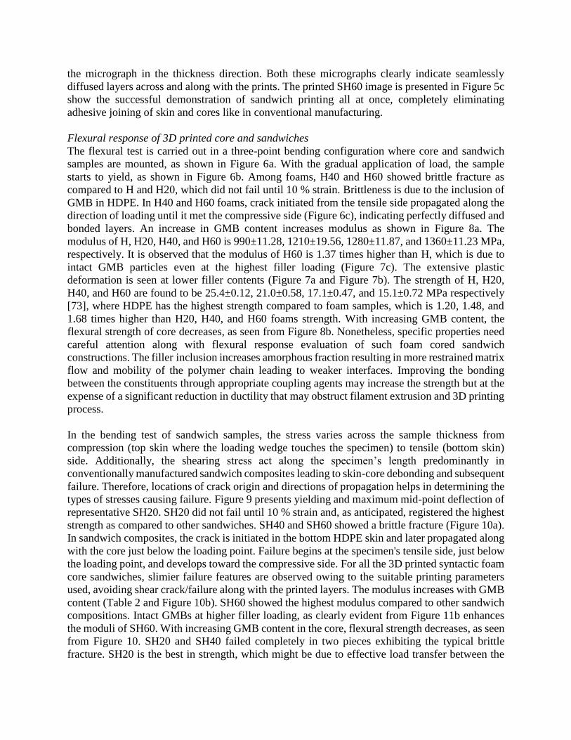
the micrograph in the thickness direction. Both these micrographs clearly indicate seamlessly
diffused layers across and along with the prints. The printed SH60 image is presented in Figure 5c
show the successful demonstration of sandwich printing all at once, completely eliminating
adhesive joining of skin and cores like in conventional manufacturing.
Flexural response of 3D printed core and sandwiches
The flexural test is carried out in a three-point bending configuration where core and sandwich
samples are mounted, as shown in Figure 6a. With the gradual application of load, the sample
starts to yield, as shown in Figure 6b. Among foams, H40 and H60 showed brittle fracture as
compared to H and H20, which did not fail until 10 % strain. Brittleness is due to the inclusion of
GMB in HDPE. In H40 and H60 foams, crack initiated from the tensile side propagated along the
direction of loading until it met the compressive side (Figure 6c), indicating perfectly diffused and
bonded layers. An increase in GMB content increases modulus as shown in Figure 8a. The
modulus of H, H20, H40, and H60 is 990±11.28, 1210±19.56, 1280±11.87, and 1360±11.23 MPa,
respectively. It is observed that the modulus of H60 is 1.37 times higher than H, which is due to
intact GMB particles even at the highest filler loading (Figure 7c). The extensive plastic
deformation is seen at lower filler contents (Figure 7a and Figure 7b). The strength of H, H20,
H40, and H60 are found to be 25.4±0.12, 21.0±0.58, 17.1±0.47, and 15.1±0.72 MPa respectively
[73], where HDPE has the highest strength compared to foam samples, which is 1.20, 1.48, and
1.68 times higher than H20, H40, and H60 foams strength. With increasing GMB content, the
flexural strength of core decreases, as seen from Figure 8b. Nonetheless, specific properties need
careful attention along with flexural response evaluation of such foam cored sandwich
constructions. The filler inclusion increases amorphous fraction resulting in more restrained matrix
flow and mobility of the polymer chain leading to weaker interfaces. Improving the bonding
between the constituents through appropriate coupling agents may increase the strength but at the
expense of a significant reduction in ductility that may obstruct filament extrusion and 3D printing
process.
In the bending test of sandwich samples, the stress varies across the sample thickness from
compression (top skin where the loading wedge touches the specimen) to tensile (bottom skin)
side. Additionally, the shearing stress act along the specimen’s length predominantly in
conventionally manufactured sandwich composites leading to skin-core debonding and subsequent
failure. Therefore, locations of crack origin and directions of propagation helps in determining the
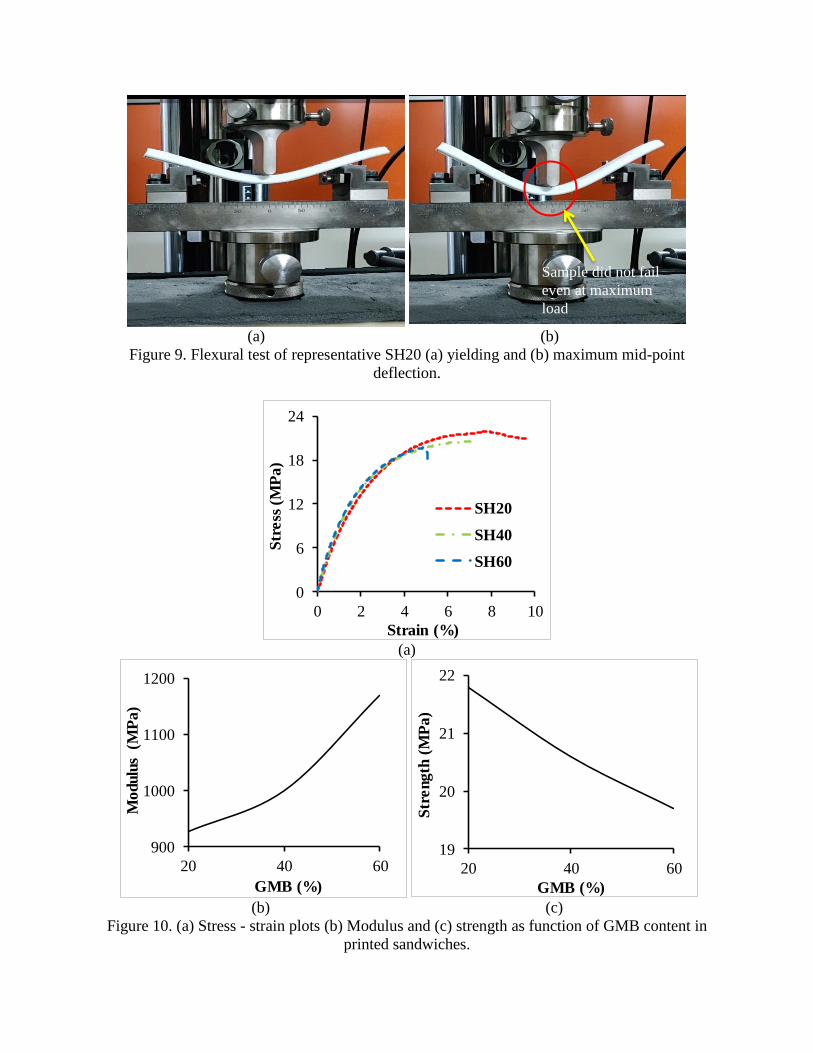
types of stresses causing failure. Figure 9 presents yielding and maximum mid-point deflection of
representative SH20. SH20 did not fail until 10 % strain and, as anticipated, registered the highest
strength as compared to other sandwiches. SH40 and SH60 showed a brittle fracture (Figure 10a).
In sandwich composites, the crack is initiated in the bottom HDPE skin and later propagated along
with the core just below the loading point. Failure begins at the specimen's tensile side, just below
the loading point, and develops toward the compressive side. For all the 3D printed syntactic foam
core sandwiches, slimier failure features are observed owing to the suitable printing parameters
used, avoiding shear crack/failure along with the printed layers. The modulus increases with GMB
content (Table 2 and Figure 10b). SH60 showed the highest modulus compared to other sandwich
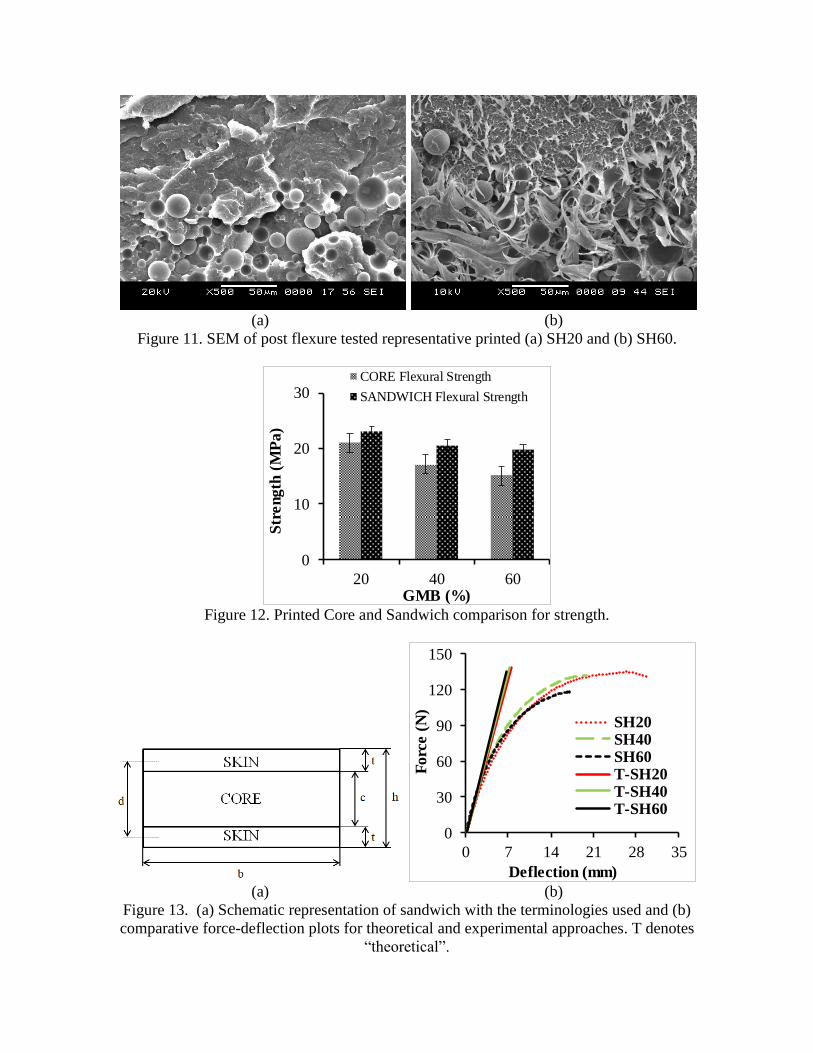
compositions. Intact GMBs at higher filler loading, as clearly evident from Figure 11b enhances
the moduli of SH60. With increasing GMB content in the core, flexural strength decreases, as seen
from Figure 10. SH20 and SH40 failed completely in two pieces exhibiting the typical brittle
fracture. SH20 is the best in strength, which might be due to effective load transfer between the
constituents. This observation is based on the absence of plastic deformation of HDPE, as seen in
Figure 11a. The excessive plastic deformation of the matrix at higher filler loading makes SH60
perform lower as compared to SH20. Nonetheless, the specific strength of SH60 is 1.1 times higher
than that of SH20. In the case of SH40 and SH60, the crack has initiated near the mid-span of the
specimen and propagated vertically across the thickness of the core and reaches the upper HDPE
skin. The top skin's progressive failure reduces the rate of drop in stress and provides extra strain
before failure. The interfacial failure is a common thing in shear stress that influenced sandwich
composites [73]. Nevertheless, in the one-shot printed syntactic foam core sandwiches as presented
in this paper, none of them exhibited interfacial separation between core and skin owing to perfect
and seamless bonding (Figure 5). Figure 12 presents a flexural strength comparison between
printed core and respective sandwiches. Though strength is seen to be decreasing with GMBs
addition, specific flexural strength increases and is a crucial factor in weight-sensitive structural
applications. The flexural strength of SH20, SH40, and SH60 is 1.05, 1.22, 1.35 times higher than
their respective H20, H40, and H60 cores, indicating the potential benefit of realizing all at once
3D printed syntactic foam core sandwich. Based on the experimental investigations in this study,
SH60 has the highest specific modulus and strength values, which can be exploited for potential
weight applications without compromising the mechanical properties.
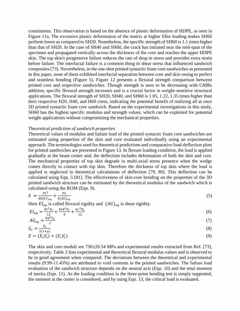
Theoretical prediction of sandwich properties
Theoretical values of modulus and failure load of the printed syntactic foam core sandwiches are
estimated using properties of the skin and core evaluated individually using an experimental
approach. The terminologies used for theoretical predictions and comparative load-deflection plots
for printed sandwiches are presented in Figure 13. In flexure loading condition, the load is applied
gradually at the beam center and, the deflection includes deformation of both the skin and core.
The mechanical properties of top skin degrade in multi-axial stress presence when the wedge
comes directly in contact with top skin. Therefore the thickness of top skin where the load is
applied is neglected in theoretical calculations of deflection [79, 80]. This deflection can be
calculated using Eqn. 5 [81]. The effectiveness of skin-core bonding on the properties of the 3D
printed sandwich structure can be estimated by the theoretical modulus of the sandwich which is
calculated using the ROM (Eqn. 9).
𝛿 = 𝑃𝐿3
48(𝐸𝐼)𝑒𝑞+
𝑃𝐿
4(𝐴𝐺)𝑒𝑞 (5)
Here 𝐸𝐼𝑒𝑞 is called flexural rigidity and (𝐴𝐺)𝑒𝑞 is shear rigidity.
𝐸𝐼𝑒𝑞 =𝑏𝑡3𝐸𝑠
12+
𝑏𝑡𝑑2𝐸𝑠
4+
𝑏𝑐3𝐸𝑐
12 (6)
𝐴𝐺𝑒𝑞 =𝑏𝑑2𝐺𝑐
𝐶 (7)
𝐺𝑐 =𝐸𝑐
2(1+𝜇) (8)
𝐸 = (𝐸𝑠𝑉𝑠) + (𝐸𝑐𝑉𝑐) (9)
The skin and core moduli are 730±20.54 MPa and experimental results extracted from Ref. [73],
respectively. Table 2 lists experimental and theoretical flexural modulus values and is observed to
be in good agreement when compared. The deviations between the theoretical and experimental
results (9.99-11.45%) are attributed to void contents in the printed sandwiches. The failure load
evaluation of the sandwich structure depends on the neutral axis (Eqn. 10) and the total moment
of inertia (Eqn. 11). As the loading condition in the three-point bending test is simply supported,
the moment at the center is considered, and by using Eqn. 13, the critical load is evaluated.

𝑌 =(𝐴𝑠𝐸𝑠𝑌𝑠)+(𝐴𝑐𝐸𝑐𝑌𝑐)
(𝐴𝑠𝐸𝑠)+(𝐴𝑐𝐸𝑐) (10)
𝐼𝑡 =(𝐸𝑐𝐼𝐶+𝐸𝑠𝐼𝑠)
𝐸𝑐 (11)
𝜎𝑓𝑚𝑎𝑥 =𝑛𝑀𝑌𝑚𝑎𝑥
𝐼𝑡 (12)
𝑀 =𝑃
2×
𝐿
2 (13)
Table 3 presents the theoretical and experimental critical load estimations for printed sandwiches
and is noted to be decreasing with increasing GMB content, which might be due to again higher
void content at higher filler loadings. The deviation between the experimental and theoretical loads
is noted to be in very close good agreement up to half of the maximum load (Figure 13b). Such
theoretical approaches help in predicting the sandwich properties beforehand, which in turn
decides a broad range of possible applications. The load-deflection cure for experimental and
theoretical predictions is represented in Figure 13b.
Failure mode of sandwich structure
The type of sandwich failure strongly depends on skin geometry, strength and core material [49,
82]. The three possible failure modes in sandwich composites under flexure are indentation, shear,
and micro buckling/face wrinkling. The sandwich faceplates remain elastic during core indentation
and shear failures [83]. Indentation creeps in when compressive yield strength matches with
stresses developed through the thickness of the core, as shown in Figure 14a. The plastic
indentation zone (λp - core reactive force equals core compressive strength) and elastic indentation
zone (λe - reactive force equals kw) forms the total indentation region. In case of shear failure,
radial shear strain in core exceeds failure strain. In earlier efforts faceplates contribution is ignored
[84, 85] while circumferential hinges work is accounted for their consideration [86]. The bottom
skin fails first as it is subjected to tension while micro buckling/face wrinkling surfaces on the top
skin (compressive side). Sandwich structures with ductile skins failed in the bottom skin, while
those with the brittle ones failed with micro-buckling in the top skin [87]. Generally, when the
load is applied to the sandwich structure, the skin undergoes tensile/compressive failure, whereas
core undergoes shear failure. The shear is not observed for all the tested sandwiches. A linear
indentation is observed at the point where wedge directly comes in contact with top skin and when
the load gradually increases, compressive stresses are induced on the top skin resulting in
wrinkling at the center for SH20 (Figure 14c). In the present work the indentation failure is
observed in SH40 and SH60 samples, as seen from the representative image in Figure 14d. None
of the samples failed in shear. All the samples except SH20 fractured just below the loading point
in an approximately straight line, as seen from Figure 14d. The indention is located in the marked
area of Figure 14d on the fractured surface of the top skin. Also, crack initiation at the bottom skin,
and shear failure of the core is observed in SH40 and SH60 due to a higher amount of stiffer GMBs
inclusion leading to brittle behavior. Similar failure features except shear are observed for the
printed sandwiches developed in the present work [87-91].
Conclusion
The present work dealt with the flexural response of all at once 3D printed GMB/HDPE syntactic
foam core sandwich. The results are summarized as follows:
The suitable printing parameters employed for all at once 3D printed syntactic foam core
sandwich resulted in seamless bonding at the skin-core interface.

The printed SH60 has a weight-saving potential of ~22%.
Voids in the core enhance energy absorbing capabilities and make them three-phase
syntactic foams.
SH60 sandwich exhibits the highest specific modulus and strength.
3D printed sandwich has superior strength and is in the range of 1.05-1.35 times as
compared to their respective foam cores.
Shear failure, which is very common, is not observed in 3D printed sandwich constructions.
Experimental results are in good agreement with theoretical predictions.
The higher specific mechanical properties of 3D printed syntactic foam core sandwiches compared
to core counterparts as observed in the present work, opens new avenues of exploring different
skin and core combinations in addition to improving the interfacial bonding between the
constituents by suitable filler surface treatments. Further, 3D printing makes the possibility of
realizing joint less (leak proof) geometrically complex sandwich constructions, which shall act as
a great boon in marine, automobile, and aerospace sectors.
Acknowledgment
The authors wish to acknowledge the support of the SPARC grant (SPARC/2018-2019/P439/SL),
Govt. of India. The authors would also like to acknowledge the Mechanical Engineering
Department of the National Institute of Technology, Karnataka, Surathkal, for providing the
facilities and support for conducting research work. The authors also wish to acknowledge U.S.
Office of Naval Research - Young Investigator Program award [Grant No.: N00014-19-1-2206]
for support towards the work presented here.
Data availability
The raw/processed data required to reproduce these findings cannot be shared at this time as the
data also forms part of an ongoing study.
References
1. Ngo, T.D., A. Kashani, G. Imbalzano, K.T. Nguyen, and D. Hui, Additive manufacturing
(3D printing): A review of materials, methods, applications and challenges. Composites
Part B: Engineering, 2018. 143: p. 172-196.
2. Singh, S.R., Seeram Singh, Rupinder, Material issues in additive manufacturing: A review.
Journal of Manufacturing Processes, 2017. 25: p. 185-200.
3. Stansbury, J.W. and M.J. Idacavage, 3D printing with polymers: Challenges among
expanding options and opportunities. Dental Materials, 2016. 32(1): p. 54-64.
4. Tofail, S.A., E.P. Koumoulos, A. Bandyopadhyay, S. Bose, L. O’Donoghue, and C.
Charitidis, Additive manufacturing: scientific and technological challenges, market uptake
and opportunities. Materials today, 2018. 21(1): p. 22-37.
5. Saltzman, D., M. Bichnevicius, S. Lynch, T.W. Simpson, E.W. Reutzel, C. Dickman, and
R. Martukanitz, Design and evaluation of an additively manufactured aircraft heat
exchanger. Applied Thermal Engineering, 2018. 138: p. 254-263.
6. Huang, R., M. Riddle, D. Graziano, J. Warren, S. Das, S. Nimbalkar, J. Cresko, and E.
Masanet, Energy and emissions saving potential of additive manufacturing: the case of
lightweight aircraft components. Journal of Cleaner Production, 2016. 135: p. 1559-1570.

7. Fateri, M., A. Kaouk, A. Cowley, S. Siarov, M.V. Palou, F.G. González, R. Marchant, S.
Cristoforetti, and M. Sperl, Feasibility study on additive manufacturing of recyclable
objects for space applications. Additive Manufacturing, 2018. 24: p. 400-404.
8. Gill, S., H. Arora, and V. Sheth, On the development of Antenna feed array for space
applications by additive manufacturing technique. Additive Manufacturing, 2017. 17: p.
39-46.
9. Schwarzer, E., S. Holtzhausen, U. Scheithauer, C. Ortmann, T. Oberbach, T. Moritz, and
A. Michaelis, Process development for additive manufacturing of functionally graded
alumina toughened zirconia components intended for medical implant application. Journal
of the European Ceramic Society, 2019. 39(2-3): p. 522-530.
10. Javaid, M. and A. Haleem, Additive manufacturing applications in medical cases: A
literature based review. Alexandria Journal of Medicine, 2018. 54(4): p. 411-422.
11. Zeltmann, S.E., N. Gupta, N.G. Tsoutsos, M. Maniatakos, J. Rajendran, and R. Karri,
Manufacturing and security challenges in 3D printing. JOM, 2016. 68(7): p. 1872-1881.
12. Dul, S., L. Fambri, and A. Pegoretti, Fused deposition modelling with ABS–graphene
nanocomposites. Composites Part A: Applied Science and Manufacturing, 2016. 85: p.
181-191.
13. Tymrak, B., M. Kreiger, and J.M. Pearce, Mechanical properties of components fabricated
with open-source 3-D printers under realistic environmental conditions. Materials &
Design, 2014. 58: p. 242-246.
14. Domingo-Espin, M., J.M. Puigoriol-Forcada, A.-A. Garcia-Granada, J. Llumà, S. Borros,
and G. Reyes, Mechanical property characterization and simulation of fused deposition
modeling Polycarbonate parts. Materials & Design, 2015. 83: p. 670-677.
15. Spoerk, M., F. Arbeiter, H. Cajner, J. Sapkota, and C. Holzer, Parametric optimization of
intra‐ and inter‐ layer strengths in parts produced by extrusion‐ based additive
manufacturing of poly (lactic acid). Journal of applied polymer science, 2017. 134(41): p.
45401.
16. Bourell, D., B. Stucker, D. Espalin, K. Arcaute, D. Rodriguez, F. Medina, M. Posner, and
R. Wicker, Fused deposition modeling of patient‐ specific polymethylmethacrylate
implants. Rapid Prototyping Journal, 2010. 16(3): p. 164-173.
17. Beesetty, P., B. Patil, and M. Doddamani, Mechanical behavior of additively manufactured
Nanoclay/HDPE nanocomposites. Composite Structures, 2020. 247: p. 112442.
18. Doddamani, M., Dynamic mechanical analysis of 3D printed eco-friendly lightweight
composite. Composites Communications, 2020. 19: p. 177-181.
19. Gupta, N. and M. Doddamani, 3D Printing of Syntactic Foams for Marine Applications, in
Advances in Thick Section Composite and Sandwich Structures. 2020, Springer. p. 407-
438.
20. Singh, R., S. Singh, and F. Fraternali, Development of in-house composite wire based feed
stock filaments of fused deposition modelling for wear-resistant materials and structures.
Composites Part B: Engineering, 2016. 98: p. 244-249.
21. Spoerk, M., F. Arbeiter, I. Raguž, G. Weingrill, T. Fischinger, G. Traxler, S. Schuschnigg,
L. Cardon, and C. Holzer, Polypropylene filled with glass spheres in extrusion‐ based
additive manufacturing: effect of filler size and printing chamber temperature.
Macromolecular Materials and Engineering, 2018. 303(7): p. 1800179.

22. Singh, A.K., A.J. Deptula, R. Anawal, M. Doddamani, and N. Gupta, Additive
manufacturing of three-phase syntactic foams containing glass microballoons and air
pores. JOM, 2019. 71(4): p. 1520-1527.
23. Masood, S. and W. Song, Development of new metal/polymer materials for rapid tooling
using fused deposition modelling. Materials & design, 2004. 25(7): p. 587-594.
24. Patil, B., B.R. Bharath Kumar, and M. Doddamani, Compressive behavior of fly ash based
3D printed syntactic foam composite. Materials Letters, 2019. 254: p. 246-249.
25. Patil, B., B.R. Bharath Kumar, S. Bontha, V.K. Balla, S. Powar, V. Hemanth Kumar, S.N.
Suresha, and M. Doddamani, Eco-friendly lightweight filament synthesis and mechanical
characterization of additively manufactured closed cell foams. Composites Science and
Technology, 2019. 183: p. 107816.
26. Singh, A.K., B. Patil, N. Hoffmann, B. Saltonstall, M. Doddamani, and N. Gupta, Additive
manufacturing of syntactic foams: Part 1: development, properties, and recycling potential
of filaments. JOM, 2018. 70(3): p. 303-309.
27. Singh, A.K., B. Saltonstall, B. Patil, N. Hoffmann, M. Doddamani, and N. Gupta, Additive
manufacturing of syntactic foams: Part 2: specimen printing and mechanical property
characterization. JOM, 2018. 70(3): p. 310-314.
28. Brenken, B., E. Barocio, A. Favaloro, V. Kunc, and R.B. Pipes, Fused filament fabrication
of fiber-reinforced polymers: A review. Additive Manufacturing, 2018. 21: p. 1-16.
29. Hofmann, D.C., J. Kolodziejska, S. Roberts, R. Otis, R.P. Dillon, J.-O. Suh, Z.-K. Liu, and
J.-P. Borgonia, Compositionally graded metals: A new frontier of additive manufacturing.
Journal of Materials Research, 2014. 29(17): p. 1899-1910.
30. Yap, Y. and W. Yeong, Additive manufacture of fashion and jewellery products: a mini
review: This paper provides an insight into the future of 3D printing industries for fashion
and jewellery products. Virtual and Physical Prototyping, 2014. 9(3): p. 195-201.
31. Lee, J.M., M. Zhang, and W.Y. Yeong, Characterization and evaluation of 3D printed
microfluidic chip for cell processing. Microfluidics and Nanofluidics, 2016. 20(1): p. 1-15.
32. Yeong, W.-Y., C.-K. Chua, K.-F. Leong, M. Chandrasekaran, and M.-W. Lee.
Development of scaffolds for tissue engineering using a 3D inkjet. in Virtual Modelling
and Rapid Manufacturing: Advanced Research in Virtual and Rapid Prototyping Proc. 2nd
Int. Conf. on Advanced Research in Virtual and Rapid Prototyping, 28 Sep-1 Oct 2005,
Leiria, Portugal. 2005. CRC Press.
33. Garcia, C.D., K. Shahapurkar, M. Doddamani, G.M. Kumar, and P. Prabhakar, Effect of
arctic environment on flexural behavior of fly ash cenosphere reinforced epoxy syntactic
foams. Composites Part B: Engineering, 2018. 151: p. 265-273.
34. Shahapurkar, K., V.B. Chavan, M. Doddamani, and G.C.M. Kumar, Influence of surface
modification on wear behavior of fly ash cenosphere/epoxy syntactic foam. Wear, 2018.
414-415: p. 327-340.
35. Ashrith, H., M. Doddamani, V. Gaitonde, and N. Gupta, Hole quality assessment in drilling
of glass microballoon/epoxy syntactic foams. JOM, 2018. 70(7): p. 1289-1294.
36. Doddamani, M., Influence of microballoon wall thickness on dynamic mechanical analysis
of closed cell foams. Materials Research Express, 2020. 6(12): p. 125348.
37. Doddamani, M. and S. Kulkarni, Dynamic response of fly ash reinforced functionally
graded rubber composite sandwiches-a Taguchi approach. International Journal of
Engineering, Science and Technology, 2011. 3(1): p. 166-182.

38. Doddamani, M. and S. Kulkarni, Behavior of sandwich beams with functionally graded
rubber core in three point bending. Polymer composites, 2011. 32(10): p. 1541-1551.
39. Gupta, N., S.E. Zeltmann, D.D. Luong, and M. Doddamani, 7—Core Materials for Marine
Sandwich Structures. Marine Composites: Design and Performance, 2018: p. 187.
40. Breunig, P., V. Damodaran, K. Shahapurkar, S. Waddar, M. Doddamani, P. Jeyaraj, and P.
Prabhakar, Dynamic impact behavior of syntactic foam core sandwich composites. Journal
of Composite Materials, 2020. 54(4): p. 535-547.
41. Waddar, S., J. Pitchaimani, and M. Doddamani, Effect of thermal loading on syntactic foam
sandwich composite. Polymer Composites, 2020. 41(5): p. 1774-1784.
42. Mondal, D.P., N. Jha, A. Badkul, S. Das, and R. Khedle, High temperature compressive
deformation behaviour of aluminum syntactic foam. Materials Science and Engineering:
A, 2012. 534: p. 521-529.
43. Orbulov, I.N., Metal matrix syntactic foams produced by pressure infiltration—The effect
of infiltration parameters. Materials Science and Engineering: A, 2013. 583: p. 11-19.
44. Taherishargh, M., M.A. Sulong, I.V. Belova, G.E. Murch, and T. Fiedler, On the particle
size effect in expanded perlite aluminium syntactic foam. Materials & Design (1980-2015),
2015. 66: p. 294-303.
45. Yu, M., P. Zhu, and Y. Ma, Experimental study and numerical prediction of tensile strength
properties and failure modes of hollow spheres filled syntactic foams. Computational
materials science, 2012. 63: p. 232-243.
46. Gupta, N. and W. Ricci, Comparison of compressive properties of layered syntactic foams
having gradient in microballoon volume fraction and wall thickness. Materials Science and
Engineering: A, 2006. 427(1-2): p. 331-342.
47. Bunn, P. and J.T. Mottram, Manufacture and compression properties of syntactic foams.
Composites, 1993. 24(7): p. 565-571.
48. Labella, M., V.C. Shunmugasamy, O.M. Strbik III, and N. Gupta, Compressive and
thermal characterization of syntactic foams containing hollow silicon carbide particles
with porous shell. Journal of Applied Polymer Science, 2014. 131(17): p. 40689.
49. Gibson, L.J. and M.F. Ashby, Cellular solids: structure and properties. 1999: Cambridge
university press.
50. Bitzer, T., Honeycomb technology: materials, design, manufacturing, applications and
testing. 1997: Springer Science & Business Media.
51. Bonnard, J.-C., Thermoplastic honeycomb core: an innovative continuous process. JEC
composites, 2004(7): p. 73-75.
52. Zuhri, M., Z. Guan, and W. Cantwell, The mechanical properties of natural fibre based
honeycomb core materials. Composites Part B: Engineering, 2014. 58: p. 1-9.
53. Rashed, M., M. Ashraf, R. Mines, and P.J. Hazell, Metallic microlattice materials: A
current state of the art on manufacturing, mechanical properties and applications.
Materials & Design, 2016. 95: p. 518-533.
54. Schaedler, T.A. and W.B. Carter, Architected cellular materials. Annual Review of
Materials Research, 2016. 46: p. 187-210.
55. Compton, B.G. and J.A. Lewis, 3D‐ printing of lightweight cellular composites. Advanced
materials, 2014. 26(34): p. 5930-5935.
56. Niknam, H. and A.H. Akbarzadeh, Thermo-mechanical bending of architected functionally
graded cellular beams. Composites Part B: Engineering, 2019. 174: p. 107060.

57. Niknam, H., A.H. Akbarzadeh, D. Rodrigue, and D. Therriault, Architected multi-
directional functionally graded cellular plates. Materials & Design, 2018. 148: p. 188-202.
58. Hou, Y., R. Neville, F. Scarpa, C. Remillat, B. Gu, and M. Ruzzene, Graded conventional-
auxetic Kirigami sandwich structures: Flatwise compression and edgewise loading.
Composites Part B: Engineering, 2014. 59: p. 33-42.
59. Hou, Y., Y.H. Tai, C. Lira, F. Scarpa, J.R. Yates, and B. Gu, The bending and failure of
sandwich structures with auxetic gradient cellular cores. Composites Part A: Applied
Science and Manufacturing, 2013. 49: p. 119-131.
60. Yalkin, H.E., B.M. Icten, and T. Alpyildiz, Enhanced mechanical performance of foam
core sandwich composites with through the thickness reinforced core. Composites Part B:
Engineering, 2015. 79: p. 383-391.
61. Liu, J., J. Tao, F. Li, and Z. Zhao, Flexural properties of a novel foam core sandwich
structure reinforced by stiffeners. Construction and Building Materials, 2020. 235: p.
117475.
62. Sharaf, T. and A. Fam, Analysis of large scale cladding sandwich panels composed of
GFRP skins and ribs and polyurethane foam core. Thin-Walled Structures, 2013. 71: p.
91-101.
63. CoDyre, L., K. Mak, and A. Fam, Flexural and axial behaviour of sandwich panels with
bio-based flax fibre-reinforced polymer skins and various foam core densities. Journal of
Sandwich Structures & Materials, 2018. 20(5): p. 595-616.
64. Liu, W., F. Zhang, L. Wang, Y. Qi, D. Zhou, and B. Su, Flexural performance of sandwich
beams with lattice ribs and a functionally multilayered foam core. Composite Structures,
2016. 152: p. 704-711.
65. Gupta, N., E. Woldesenbet, K. Hore, and S. Sankaran, Response of syntactic foam core
sandwich structured composites to three-point bending. Journal of Sandwich Structures &
Materials, 2002. 4(3): p. 249-272.
66. Grosjean, F., N. Bouchonneau, D. Choqueuse, and V. Sauvant-Moynot, Comprehensive
analyses of syntactic foam behaviour in deepwater environment. Journal of Materials
Science, 2009. 44(6): p. 1462-1468.
67. Hobaica, E. and S. Cook, The characteristics of syntactic foams used for buoyancy. Journal
of cellular plastics, 1968. 4(4): p. 143-148.
68. Bharath Kumar, B., S.E. Zeltmann, M. Doddamani, N. Gupta, S. Gurupadu, and R. Sailaja,
Effect of cenosphere surface treatment and blending method on the tensile properties of
thermoplastic matrix syntactic foams. Journal of Applied Polymer Science, 2016. 133(35):
p. 43881.
69. Kumar, B.B., M. Doddamani, S.E. Zeltmann, N. Gupta, and S. Ramakrishna, Data
characterizing tensile behavior of cenosphere/HDPE syntactic foam. Data in brief, 2016.
6: p. 933-941.
70. Jeyachandran, P., S. Bontha, S. Bodhak, V.K. Balla, B. Kundu, and M. Doddamani,
Mechanical behaviour of additively manufactured bioactive glass/high density
polyethylene composites. Journal of the Mechanical Behavior of Biomedical Materials,
2020. 108: p. 103830.
71. Chrissafis, K., K. Paraskevopoulos, I. Tsiaoussis, and D. Bikiaris, Comparative study of
the effect of different nanoparticles on the mechanical properties, permeability, and
thermal degradation mechanism of HDPE. Journal of Applied Polymer Science, 2009.
114(3): p. 1606-1618.

72. Alothman, O.Y., Processing and characterization of high density polyethylene/ethylene
vinyl acetate blends with different VA contents. Advances in Materials Science and
Engineering, 2012. 2012.
73. Bharath H S, D.B., Pavana Prabhakar, and M. Doddamani, 3D Printed Lightweight
Composite Foams. . ACS Omega, 2020. Under Revision.
74. Kumar, B.B., M. Doddamani, S.E. Zeltmann, N. Gupta, S. Gurupadu, and R. Sailaja, Effect
of particle surface treatment and blending method on flexural properties of injection-
molded cenosphere/HDPE syntactic foams. Journal of materials science, 2016. 51(8): p.
3793-3805.
75. Jayavardhan, M., B.B. Kumar, M. Doddamani, A.K. Singh, S.E. Zeltmann, and N. Gupta,
Development of glass microballoon/HDPE syntactic foams by compression molding.
Composites Part B: Engineering, 2017. 130: p. 119-131.
76. Bharath, H.S., D. Bonthu, S. Gururaja, P. Prabhakar, and M. Doddamani, Additive
Manufacturing of Syntactic Foam Cored Sandwich composite. Composite Structures,
2020. Under Review.
77. Gupta, N., E. Woldesenbet, and P. Mensah, Compression properties of syntactic foams:
effect of cenosphere radius ratio and specimen aspect ratio. Composites Part A: Applied
Science and Manufacturing, 2004. 35(1): p. 103-111.
78. Gupta, N. and E. Woldesenbet, Characterization of flexural properties of syntactic foam
core sandwich composites and effect of density variation. Journal of composite materials,
2005. 39(24): p. 2197-2212.
79. Budiansky, B. and N.A. Fleck, Compressive failure of fibre composites. Journal of the
Mechanics and Physics of Solids, 1993. 41(1): p. 183-211.
80. Manalo, A., T. Aravinthan, W. Karunasena, and M. Islam, Flexural behaviour of structural
fibre composite sandwich beams in flatwise and edgewise positions. Composite Structures,
2010. 92(4): p. 984-995.
81. Omar, M.Y., C. Xiang, N. Gupta, O.M. Strbik, and K. Cho, Syntactic foam core metal
matrix sandwich composite under bending conditions. Materials & Design, 2015. 86: p.
536-544.
82. Ashby, M.F., A. Evans, N.A. Fleck, L.J. Gibson, J.W. Hutchinson, and H.N. Wadley, Metal
foams: a design guide-Butterworth-Heinemann, Oxford, UK, ISBN 0-7506-7219-6,
Published 2000, Hardback, 251 pp., $75.00. Materials and Design, 2002. 1(23): p. 119.
83. Steeves, C.A. and N.A. Fleck, Collapse mechanisms of sandwich beams with composite
faces and a foam core, loaded in three-point bending. Part I: analytical models and
minimum weight design. International Journal of Mechanical Sciences, 2004. 46(4): p. 561-
583.
84. Allen, H., Analysis and Design of Structural Sandwich Panelsn Pergamon Press. 1969,
London.
85. Plantema, F.J., Sandwich construction: the bending and buckling of sandwich beams,
plates, and shells. 1966.
86. Ashby, M.F., T. Evans, N.A. Fleck, J. Hutchinson, H. Wadley, and L. Gibson, Metal foams:
a design guide. 2000: Elsevier.
87. Triantafillou, T.C. and L.J. Gibson, Failure mode maps for foam core sandwich beams.
Materials Science and Engineering, 1987. 95: p. 37-53.
88. Omar, M.Y., C. Xiang, N. Gupta, O.M. Strbik III, and K. Cho, Syntactic foam core metal
matrix sandwich composite: Compressive properties and strain rate effects. Materials
Science and Engineering: A, 2015. 643: p. 156-168.
89. Triantafillou, T.C. and L.J. Gibson, Minimum weight design of foam core sandwich panels
for a given strength. Materials Science and Engineering, 1987. 95: p. 55-62.
90. Lingaiah, K. and B. Suryanarayana, Strength and stiffness of sandwich beams in bending.
Experimental Mechanics, 1991. 31(1): p. 1-7.
91. Theotokoglou, E.E., Analytical determination of the ultimate strength of sandwich beams.
Applied Composite Materials, 1996. 3(5): p. 345-353.

Table 1. Density, void % and weight saving potential estimations of printed sandwich.
Material 𝑉𝑓 𝜌𝑒𝑥𝑝 𝜌𝑡ℎ 𝜙𝑣 Weight Saving
Potential (%) w.r.t H
SH20 20 879.35±14 897.5 2.02 5.14
SH40 40 777.38±16 845 8.00 16.14
SH60 60 723.87±11 792.5 8.66 21.91
Table 2. Flexural response of prints.
Materials Experimental
Modulus (MPa)
Theoretical
Modulus (MPa)
Strength
(MPa)
Fracture
strength (MPa)
Fracture
strain (%)
SH20 927±18.46 1067.83 21.80±0.45 ----- -----
SH40 1000±13.58 1126.09 20.53±0.52 20.25±0.57 7.13±0.15
SH60 1050±12.86 1186.57 19.72±0.80 19.72±0.77 5.20±0.10
Table 3. Experimental and theoretical critical load estimations.
Material Experimental
Critical load (N)
Theoretical Critical
load (N) from Eqn. 13
Deviation
(%)
SH20 135 138.67 2.57
SH40 133 138.57 4.10
SH60 118 135.60 12.97
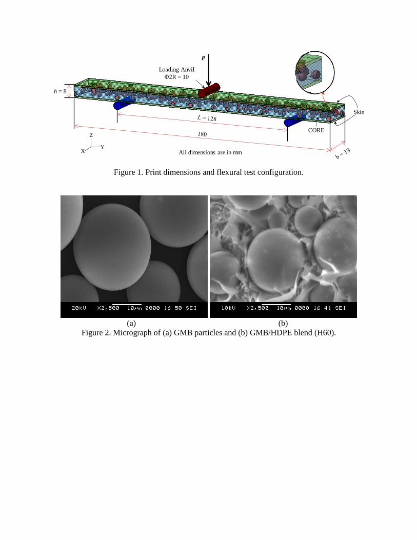
Figure 1. Print dimensions and flexural test configuration.
(a) (b)
Figure 2. Micrograph of (a) GMB particles and (b) GMB/HDPE blend (H60).
h = 8
P
CORE
Skin
Loading Anvil
Φ2R = 10
YX
Z
All dimensions are in mm

(a) (b)
(c)
Figure 3. Cross-sectional SEM micrographs of (a) H20, (b) H40 and (c) H60 filaments.

(a) (b)
(c)
Figure 4. Freeze fractured micrographs of (a) SH20, (b) SH40 and (c) SH60 at skin-core
interface.

(a) (b) (c)
Figure 5. As printed freeze fractured micrograph of sandwich (a) across the thickness (b) along
the thickness. (c) representative printed SH60 sandwich composite.
SKIN
CORE
CORE
CORE
SKIN
CORE
SKIN

(a) (b)
(c)
Figure 6. (a) Representative H60 mounting in flexure mode (b) yielding (c) and crack initiation.
Crack Propagation
and sample failure

(a) (b)
(c)
Figure 7. Micrographs of post flexure tested (a) H20 (b) H40, and (c) H60 printed cores.
(a) (b)
Figure 8. (a) Flexural Modulus and (c) strength as a function of GMB content for H20-H60.
1200
1250
1300
1350
1400
20 40 60
Modulu
s (M
Pa
)
GMB (%)
14
16
18
20
22
20 40 60
Str
ength
(M
Pa)
GMB (%)
(a) (b)
Figure 9. Flexural test of representative SH20 (a) yielding and (b) maximum mid-point
deflection.
(a)
(b) (c)
Figure 10. (a) Stress - strain plots (b) Modulus and (c) strength as function of GMB content in
printed sandwiches.
Sample did not fail
even at maximum
load
0
6
12
18
24
0 2 4 6 8 10
Str
ess
(M
Pa)
Strain (%)
SH20
SH40
SH60
900
1000
1100
1200
20 40 60
Modulu
s (M
Pa)
GMB (%)
19
20
21
22
20 40 60
Str
ength
(M
Pa)
GMB (%)
(a) (b)
Figure 11. SEM of post flexure tested representative printed (a) SH20 and (b) SH60.
Figure 12. Printed Core and Sandwich comparison for strength.
(a) (b)
Figure 13. (a) Schematic representation of sandwich with the terminologies used and (b)
comparative force-deflection plots for theoretical and experimental approaches. T denotes
“theoretical”.
0
10
20
30
20 40 60
Str
ength
(M
Pa)
GMB (%)
CORE Flexural Strength
SANDWICH Flexural Strength
0
30
60
90
120
150
0 7 14 21 28 35
Forc
e (
N)
Deflection (mm)
SH20SH40SH60T-SH20T-SH40T-SH60

(a) (b)
(c) (d)
Figure 14. Schematic representation of (a) core indentation and (b) failure modes observed in 3D
printed syntactic foam core sandwiches. (c) face wrinkling in SH20 and (d) indentation failure
(SH40 and SH60).
Skin
Skin
Core
Front View
Top
View
Fractured Surface