Flexural Analysis of Axially Restrained Ferro cement Slab ... 2/Issue 6/IJESIT201306_13.pdf ·...
14
ISSN: 2319-5967 ISO 9001:2008 Certified International Journal of Engineering Science and Innovative Technology (IJESIT) Volume 2, Issue 6, November 2013 115 Abstract— Ferro cement slabs having end restraints may achieve a load capacity different from those which are axially unrestrained. Consequently, analytical models proposed for flexural analysis of Ferro cement slabs may fail to predict the load capacity of slabs that are axially restrained against movement. In this paper a classical method for the analysis axially restrained slabs is modified and assessed as to its ability to predict the behavior of axially restrained Ferro cement slabs. The ultimate load based on this method grossly over predicted the slab strength mainly due to neglecting the role of important parameters such as elastic curvature and large deformation. A new approach based on the elastic and elastic-plastic behaviors of materials, large deflection and stability of the thin section slab strip was proposed for analysis. Both the ultimate load and the load-deflection response calculated using the proposed large deflection elastic- plastic method was found to be quite accurate and the obtained test / calculated ultimate load was found to be 1.05. Accordingly, the proposed analytical method can be used for calculating accurately the load capacity of axially restrained one way Ferro cement slabs having span / depth ratios up to 58. Index Terms— Curvature, Deflection, Ferro cement Slab, Stability. I. INTRODUCTION It is experimentally evident that in the case of fully axially restrained slabs, the ultimate load capacity is considerably higher than that obtained using yield line theory. This enhancement in load has been attributed to the effect of the induced compressive membrane action and the corresponding modification of the yield criterion [1]. Many analytical approaches have been proposed for calculating the ultimate load capacity of axially restrained RC slabs [2]-[6]. Such methods were found to give accurate ultimate load capacity for thick slabs. Eyre [7, 8], in two papers, presented the general concept of the maximum membrane force (MMF). The method was proposed in order to take into consideration the effect of geometric imperfections due to instability and large deformations. According to the MMF method, the maximum safe load occurs at the plastic deflection at which the maximum membrane force occurs. This load is usually smaller than the peak load associated with the load-deflection relationship. Welch [9] utilized Park and Gamble's modified rigid-plastic method [3] to develop a more general solution for axially restrained reinforced concrete slabs. The peak thrust according to compressive membrane theory occurs when the axial shortening of the slab and outward support movement (if the end supports are partially restrained) are at a maximum. It is demonstrated that estimating the peak thrust using a modification of Park and Gamble's theory gives an improved correlation with experimental data for a range of span to depth ratios ( L/h) between 2.7 and 28.3[9]. Since Ferro cement members are characterized as thin sections with large values of L/h, the methods proposed for analyzing axially restrained slabs may not be accurate for calculating the ultimate load capacity. This is due to the fact that thin sections usually suffer from large elastic deformation and instability due to flexural buckling. In this paper, simply supported ferrocement strips are analyzed as thin slabs. These strips are fully reinforced with wire mesh without skeletal reinforcement. The span / depth ratio of the slabs was larger than 22 which Welch [9] considers to be the limiting ratio for a thin slab. The proposed method for calculating the load-deflection relationship is essentially based on consideration of the elastic and plastic responses of the slab materials and its geometrical flexural instability. This paper presents a method for determining the capacity of thin, axially restrained, ferrocement slabs. Prior to presenting the final method of analysis, the possibility of using a modified form of rigid plastic analysis is considered. This approach is presented in section II. The more appropriate large deflection elastic-plastic method is presented in section III and is found to correlate well with the experimental results. Flexural Analysis of Axially Restrained Ferro cement Slab Strip Azad A. Mohammed, Yaman S. Shareef
Transcript of Flexural Analysis of Axially Restrained Ferro cement Slab ... 2/Issue 6/IJESIT201306_13.pdf ·...

ISSN: 2319-5967
ISO 9001:2008 Certified International Journal of Engineering Science and Innovative Technology (IJESIT)
Volume 2, Issue 6, November 2013
115
Abstract— Ferro cement slabs having end restraints may achieve a load capacity different from those which are axially
unrestrained. Consequently, analytical models proposed for flexural analysis of Ferro cement slabs may fail to predict the
load capacity of slabs that are axially restrained against movement. In this paper a classical method for the analysis axially
restrained slabs is modified and assessed as to its ability to predict the behavior of axially restrained Ferro cement slabs.
The ultimate load based on this method grossly over predicted the slab strength mainly due to neglecting the role of
important parameters such as elastic curvature and large deformation. A new approach based on the elastic and
elastic-plastic behaviors of materials, large deflection and stability of the thin section slab strip was proposed for analysis.
Both the ultimate load and the load-deflection response calculated using the proposed large deflection elastic- plastic
method was found to be quite accurate and the obtained test / calculated ultimate load was found to be 1.05. Accordingly,
the proposed analytical method can be used for calculating accurately the load capacity of axially restrained one way Ferro
cement slabs having span / depth ratios up to 58.
Index Terms— Curvature, Deflection, Ferro cement Slab, Stability.
I. INTRODUCTION
It is experimentally evident that in the case of fully axially restrained slabs, the ultimate load capacity is
considerably higher than that obtained using yield line theory. This enhancement in load has been attributed to the
effect of the induced compressive membrane action and the corresponding modification of the yield criterion [1].
Many analytical approaches have been proposed for calculating the ultimate load capacity of axially restrained RC
slabs [2]-[6]. Such methods were found to give accurate ultimate load capacity for thick slabs. Eyre [7, 8], in two
papers, presented the general concept of the maximum membrane force (MMF). The method was proposed in
order to take into consideration the effect of geometric imperfections due to instability and large deformations.
According to the MMF method, the maximum safe load occurs at the plastic deflection at which the maximum
membrane force occurs. This load is usually smaller than the peak load associated with the load-deflection
relationship. Welch [9] utilized Park and Gamble's modified rigid-plastic method [3] to develop a more general
solution for axially restrained reinforced concrete slabs. The peak thrust according to compressive membrane
theory occurs when the axial shortening of the slab and outward support movement (if the end supports are partially
restrained) are at a maximum. It is demonstrated that estimating the peak thrust using a modification of Park and
Gamble's theory gives an improved correlation with experimental data for a range of span to depth ratios (L/h)
between 2.7 and 28.3[9].
Since Ferro cement members are characterized as thin sections with large values of L/h, the methods proposed for
analyzing axially restrained slabs may not be accurate for calculating the ultimate load capacity. This is due to the
fact that thin sections usually suffer from large elastic deformation and instability due to flexural buckling.
In this paper, simply supported ferrocement strips are analyzed as thin slabs. These strips are fully reinforced with
wire mesh without skeletal reinforcement. The span / depth ratio of the slabs was larger than 22 which Welch [9]
considers to be the limiting ratio for a thin slab. The proposed method for calculating the load-deflection
relationship is essentially based on consideration of the elastic and plastic responses of the slab materials and its
geometrical flexural instability.
This paper presents a method for determining the capacity of thin, axially restrained, ferrocement slabs. Prior to
presenting the final method of analysis, the possibility of using a modified form of rigid plastic analysis is
considered. This approach is presented in section II. The more appropriate large deflection elastic-plastic method
is presented in section III and is found to correlate well with the experimental results.
Flexural Analysis of Axially Restrained Ferro
cement Slab Strip Azad A. Mohammed, Yaman S. Shareef

ISSN: 2319-5967
ISO 9001:2008 Certified International Journal of Engineering Science and Innovative Technology (IJESIT)
Volume 2, Issue 6, November 2013
116
II. MODIFIED RIGID- PLASTIC ANALYSIS
Since the width / thickness ratio of one-way slabs is large, the lateral buckling is not an issue and shear stress and
shear deformation are relatively small. Therefore, developing analytical methods are easier for one way slab or slab
strips as compared with the other types of slabs. The rigid plastic analysis approach was proposed basically for RC
slabs of relatively thick sections and here it will be tested for its accuracy when applied to ferrocement slabs which
are usually thin. The modified rigid-plastic approach proposed by Park and Gamble [3] in its basic form has been
used for deriving the geometrical compatibility relationship. The yield criterion adopted is that proposed by
Mansur [10] for ultimate stress distribution of ferrocement slabs.
A. Geometrical Compatibility Condition
A consideration of the compatibility of deformation of a rigid portion of slab strip leads to the following equation
based on the depths of compression zone as derived below.
cL
bLhc
2
4
2
2
(1)
The above value of cwas derived by Park and Gamble [3] and can be used for ferrocement slab analysis because
it is based on compatibility of deformations and independent on cross-section properties.
B. Stress Distribution for Yield Criterion
The method proposed by Mansur [10] (Method B) for calculating the moment capacity of a ferrocement section
uses the familiar rigid-plastic concept. The ferrocement wires are uniformly distributed throughout the
cross-section of the element. The plastic compressive stress is taken as 0.85f c. Fig. 1 shows the stress distribution
at ultimate stage for the ferrocement section.
C. Yield Criterion
For a simply supported axially restrained one-way ferrocement slab, equilibrium of forces acting on the section
shown in Fig. (2) leads to:
fTsTCC
(2) Where:
sT is the tensile forces in the skeletal steel reinforcement )( yfsAsT .
fT is the tensile force due to the ferrocement wire mesh )]([ chtuf
fT , and
C' and C is the compressive force acting at the ends of the strip given by the following two equations
cc
fC 85.0 (3)
ccfC 85.0 (4)
Substituting Eq. (3) and Eq. (4) into Eq. (2) and rearranging, gives
cc (5)
In which and are stress parameters having the following values:
cf
tufcf
85.0
85.0 , and
cf
htufyfsA
85.0
Solving Eq. (1) and (5) simultaneously provides
1
2
4
2
2
L
bLh
c (6)

ISSN: 2319-5967
ISO 9001:2008 Certified International Journal of Engineering Science and Innovative Technology (IJESIT)
Volume 2, Issue 6, November 2013
117
The axial shortening and support movement (b
) in Eq. (6), are related to the axial force uN as follows
chE
uN ,
S
uN
b and cES 1.005.0
in which S is the stiffness of the end restrained.
Fig. 1 Stress distribution across the ferrocement section Fig. 2 Rigid portion of slab strip of axial deformation
at collapse ( Mansur[10]) (Park and Gamble[3])
cE is the composite modulus of elasticity. According to Shah and Balaguru [11], cE can be calculated as follows
nRL
VmEcE 1
For the welded wire mesh, both directions are considered as a main direction (i.e. RTVRLV ) and RLV can be
calculated according to the equation proposed by Walraven and Spiereburg [12] as follows:
hLs
iNsfA
RLV 7.1
n is the modular ratio given by
mE
REn
where
RLV is the volume fraction of reinforcement in the longitudinal direction
sfA is the cross-sectional area of one wire (
2mm ).
iN is the number of layers of wires.
sL is the spacing of wires ( mm).
h is the thickness of the cross-section ( mm).
n is the modular ratio.
RE is the modulus of elasticity of reinforcement.
mE is the modulus of elasticity of mortar.
When
L
b2
is a maximum, the thrust is a maximum and this indicates the peak capacity.

ISSN: 2319-5967
ISO 9001:2008 Certified International Journal of Engineering Science and Innovative Technology (IJESIT)
Volume 2, Issue 6, November 2013
118
uNLSchEL
b
S
uN
LchE
uN
L
b
21222
Therefore, Eq.( 6 ) becomes
uNLSchE
Lh
c14
212
1
2
( 7 )
But
cc , on substituting
uNLSchE
L
hc14
212
21
( 8 )
Let
21
1
h , and
14
212
LSchEL
Both Eqs. (7) and ( 8 ) can be simplified to
uNc (9)
uNc (10)
The concrete compressive force C at a negative moment zone at the end [Fig. 2] for a strip of unit width is
statically equal to the compressive membrane force uN , or
ccfuN 85.0 (11)
Substituting Eq. (10) into Eq. (11) leads to calculating the membrane force uN per unit width of the slab as
follows:
LSchE
Lcf
cfhcf
uN
21
4
285.0
1
85.02
85.0
(12)
The moment per unit width in the center of the slab is:
c
hchchtuf
chccf
hdyfsAuM
222285.0
2
Or
22285.0
2
cchtuf
chccf
hdyfsAuM
On substituting Eq.( 9 ) and simplifying,

ISSN: 2319-5967
ISO 9001:2008 Certified International Journal of Engineering Science and Innovative Technology (IJESIT)
Volume 2, Issue 6, November 2013
119
2
2
2
85.02
85.0
85.022
NutufcfNuh
tufcf
htufcfh
dyfsAuM
(13)
The moment per unit width of the slab at the supports is given by:
2285.0
chccfuM
On substituting Eq. (10) and simplifying, the following equation is obtained
22
22
22
425.0
Nu
uNhhh
cfuM
(14)
For the end portion of the rigid – plastic slab strip, the sum of the moment for calculating the internal work is taken
as
uNuMuM .
For a slab strip under two central line load ( 2/uP ), the external virtual work is:
auP
WE2
..
while the internal virtual work is given by:
uNuMuMWI ..
On substituting the expressions for each of the force and moment terms, the I.W. becomes
22185.0
2
2
212
122
85.0
2
22
21
21
2
85.0
22..
uNcftuf
uNhcfh
tuf
hhcf
htufh
df
fsAWI
(15)
Equating the internal and external virtual work leads to
uNuMuMauP
2
Or
uNuMuMauP
2
The value of Pu then becomes
uNuMuMa
uP 2

ISSN: 2319-5967
ISO 9001:2008 Certified International Journal of Engineering Science and Innovative Technology (IJESIT)
Volume 2, Issue 6, November 2013
120
The final load-deflection equation can be written as follows
22185.0
2
2
212
122
85.0
2
22
21
21
2
85.0
22
2
uNcftuf
uNhcfh
tuf
hhcf
htufh
dyfsA
auP
(16)
Where
uP is the ultimate load (N/mm).
a is the shear span ( mm).
sA is the cross sectional area of steel (2
mm /mm).
d is the effective depth of steel ( mm).
h is the slab thickness ( mm).
tuf is the ultimate tensile strength (2
N/mm ).
,,, are stress parameters for modified rigid-plastic analysis.
cf is the concrete cylinder strength (2
N/mm ).
uN is the membrane force acting at mid-span (N/mm).
Hence the load-deflection relationship of ferrocement slab strip can be obtained using Eq. (16) and Eq. (12).
It should be noted that for the case of reinforced concrete slab strips the derived load-deflection relationship has
been suggested as being likely to accurately predict behavior when sufficient deformation occurs (i.e. is
sufficiently large) to allow full plasticity to develop at the critical section. Moreover, the load-deflection
relationship is only valid when the membrane force is compressive (Nu is positive) and when Nu become zero the
analysis is stopped.
III. LARGE DEFLECTION ELASTIC- PLASTIC METHOD
The most important shortcoming of modified rigid-plastic analysis when applied to axially-restrained thin slabs is
that it neglects elastic curvature and the significant deformations due to flexural instability. There is no doubt that
the rigid-plastic approach was proposed for analysis of thicker reinforced concrete slabs and it is expected to be not
accurate when compared with the test results for axially restrained ferrocement slab strips. This will be
demonstrated later. In this section of the paper, an alternative model is developed based on plate theory taking into
account the effect of in-plane compressive membrane forces on deformation. To simplify the derivation, the
ferrocement section is considered to be fully reinforced with wire mesh only and to have no skeletal reinforcement.
First, the moment-curvature relationship is derived taking into account the successive cracking stages that occur as
the curvature changes as well as the material characteristics in both tension and compression.
A. Idealized Stress- Strain Relationship
The idealized stress-strain relationship for ferrocement in compression is shown in Fig. (3-a). The role of wire
meshes in compressive stress is not included because it was found to be insignificant as demonstrated by many
researchers. Fig. (3-b) shows the idealized stress-strain relationship of ferrocement in tension, which is based on
three stages: elastic, elastic-plastic and plastic stages.

ISSN: 2319-5967
ISO 9001:2008 Certified International Journal of Engineering Science and Innovative Technology (IJESIT)
Volume 2, Issue 6, November 2013
121
Fig.3 Idealized stress- strain relationship of ferrocement: (a) in compression (b) in tension
B. Moment- Curvature Relationship for Elastic Stage
Figg. 4 illustrate the stress and strain distributions associated with the elastic and elastic-plastic stages at the critical
section at mid-span of a slab strip. The depth of the neutral axis, c, can be obtained using equilibrium of forces
acting on the section. The summation of forces acting on the section is equal to the vcompressive membrane
force N .
0
0c
chNydycEydycE
Solving and simplifying the above equation lead to the following equation:
hcE
Nhc
2 (17)
in which:
h is the slab thickness. N is the compressive membrane force per unit width of the slab. cE is the composite
modulus of elasticity, calculated as for modified rigid-plastic analysis and is the curvature. The limiting or
critical value of curvature is related to the first cracking strain and for the linear strain distribution is as follows
ch
crcr
In which
Ec
rfcr
and
cr is the cracking strain and rf is the modulus of rupture.
According to ACI 318M-05 Code [13]
cfrf 62.0
The flexural moment curvature relationship for this stage is given by
0
0
22
c
chdyycEdyycEeM
Upon integration, the above equations becomes:
hcchhcE
eM2
32
33
3
(18)

ISSN: 2319-5967
ISO 9001:2008 Certified International Journal of Engineering Science and Innovative Technology (IJESIT)
Volume 2, Issue 6, November 2013
122
Fig.4 Stress and strain distribution acting on ferrocement section for different cracking stage
C. Moment- Curvature Relationship for Elastic- Plastic Stage
Fig. 4 shows the stress-strain distribution for this stage. Once again, the depth of the neutral axis can be obtained
from equilibrium of forces:
ch
hc
Ndycry
crtu
rftufhcydycE
c
ydycE
0
0 (19)
Let
crtu
rftuf
By integrating and then simplifying the above equation, the depth of neutral axis is given by the following quadratic
formula
cE
hcrhcEcr
NcEhcrcrh
c
2
2
12
2
222
(20)
and the flexural moment-curvature relationship is given by
dych
hcycrydyycE
hc
cdyycEepM
22
0
0 2
By integrating and simplifying the above equation, it becomes:
23
3
2
32
33
2
6
22
2
3
3
crEccrcrhh
chcrhccr
hccEepM
(21)
The elastic-plastic stage terminates when the tensile stress in the section reaches εtu (εtu = εsy) and accordingly the
curvature becomes
ISSN: 2319-5967
ISO 9001:2008 Certified International Journal of Engineering Science and Innovative Technology (IJESIT)
Volume 2, Issue 6, November 2013
123
ch
sy
εsy is the strain corresponding to the yield stress of wire mesh and is given by
cE
yff
sy
For thin sections this curvature is not expected to be reached because due to large elastic curvature the slab may be
unstable due to flexural buckling which limits the compressive membrane force.
D. Load- Deflection Equation for Ferrocement Slab Strip
The stresses and deflections associated with thin slabs subjected to transverse loads are directly proportional to the
applied loads. This statement is valid if the deflections are small such that the slight change in geometry produced
in the loaded slab has an insignificant effect on the loads themselves. This situation changes drastically when axial
loads act simultaneously with the transverse loads. The internal moments, shear forces, stresses and deflections
then become dependent upon the magnitude of the deflections as well as the magnitude of the external loads. They
are also sensitive to slab imperfections such as initial curvature and eccentricity of axial loads. For axially
restrained slab strip or beam subjected to two central point loads (each P/2) the deflection equation was derived by
Shareef[14] and found to have the following form:
2
16
2
4
2
2
8
2
7128
3
D
NL
D
NL
D
NL
D
LP
wo (22)
Where P and N are in mmN / and D is the flexural rigidity of the slab given by
12
3Eh
D measured in mmN.
For axially restrained slab strip the load- curvature is given by
wD
N
L
x
D
PL
dx
wd
sin
2
2
2
2
(23)
At the center of the slab strip the curvature then becomes
wD
N
D
PL
2
2
(24)
E. Calculation of Membrane Force
In order to determine the compressive membrane force (N) acting on a ferrocement slab section, it is helpful to
utilise assumptions and simplifications similar to those made for the rigid-plastic analysis. If it is assumed that the
slab strip is rigid in flexure but allowed to elastic shorten. Equilibrium of forces acting on the ends of slab portion
leads to the solution for compressive membrane force. Fig. (5) shows the rigid half strip of the ferrocement slab
between the center and one end. Equilibrium of forces is given by the following relationship:
NCf
TNC (25)
But f
TCN

ISSN: 2319-5967
ISO 9001:2008 Certified International Journal of Engineering Science and Innovative Technology (IJESIT)
Volume 2, Issue 6, November 2013
124
Fig. 5 Force acting on half slab strip
Therefore:
NC
or
c
NydycE0
(26)
The depth of compression zone at the end ( c ) then becomes
cE
Nc
2 (27)
From the previous equation associated with the rigid-plastic analysis, the value of c was found to be
cwchE
NLwhc
2
2 (28)
Combining the two above equations leads to the following relationship 2
2
22
cwchE
LNwh
cEN
(29)
According to the above relationship, the solution for N must be obtained by trial and error. A direct solution for
N based on equation (29) is not possible since , w and c are dependent on membrane force N . The calculation
undertaken and presented in this paper have been based on accepting an error between the left and right side of this
equation of up to 10% as this was found to result in very small change in N..
F. Procedure for Calculation Load- Deflection Relationship
The simply supported ferrocement slab strips (without the skeletal reinforcement) allowing for compressive
membrane action can now be analyzed using the above theory. In this analysis, the effects of elastic curvature, large
deflection and instability are considered. The following stepwise approach has been used to obtain the deflection,
curvature, depth of compression zone as well as the flexural rigidity for any load increment for the whole loading
history.
1- Calculate the initial flexural rigidity (D) for the uncracked ferrocement slab section.
2- Specify the first small value of load P .
3- Specify the first small value of membrane force N .
4- Calculate the deflection from Eq. ( 22 ).
5- Calculate the curvature from Eq. ( 24 ).
6- Having the values of and N , calculate the depth of neutral axis ( c ) and check the limit of for testing that
the elastic-plastic stage is reached or not.
7- Calculate the moment corresponding to the curvature and then calculate the flexural rigidity by dividing the
moment by the curvature.
8- Calculate the correct value of membrane force N using Eq. (29) and repeat steps 3 to 7.
ISSN: 2319-5967
ISO 9001:2008 Certified International Journal of Engineering Science and Innovative Technology (IJESIT)
Volume 2, Issue 6, November 2013
125
9- Calculate the ratio of flexural rigidity (present to initial flexural rigidity) and check that is not smaller than 10 %.
If it smaller than 10 %, the analysis is stopped indicating the end of compressive membrane action ( 0c and w=
∞) and here the section is nearly fully cracked at the center of slab strip, accepting a 10% error.
10- Repeat steps 2 to 9 for another value of load to calculate deflection, curvature, membrane force and flexural
rigidity.
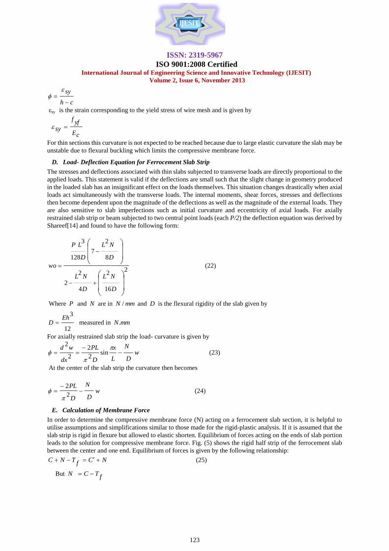
IV. VALIDATION OF THE PROPOSED METHODS
Based on the above calculation steps, a computer program was developed and all necessary data were obtained.
The theoretical predictions including those of the modified rigid-plastic analysis are compared with the test results
in Table ( 1 ).
As shown from the results of the Table ( 1 ), the modified rigid-plastic predictions is not safe and not accurate for
all slabs since the mean value for the ultimate load (Test / Theory) is 0.56. The reason for this is that the method was
proposed basically for reinforced concrete slabs of thick sections and not applicable to thin slabs like ferrocement
slabs. In contrast the predictions of the proposed large deflection elastic-plastic analysis are accurate and close to
test data. The mean value for the ultimate load (Test / Theory) is 1.05 which means the predictions are safe and very
accurate.
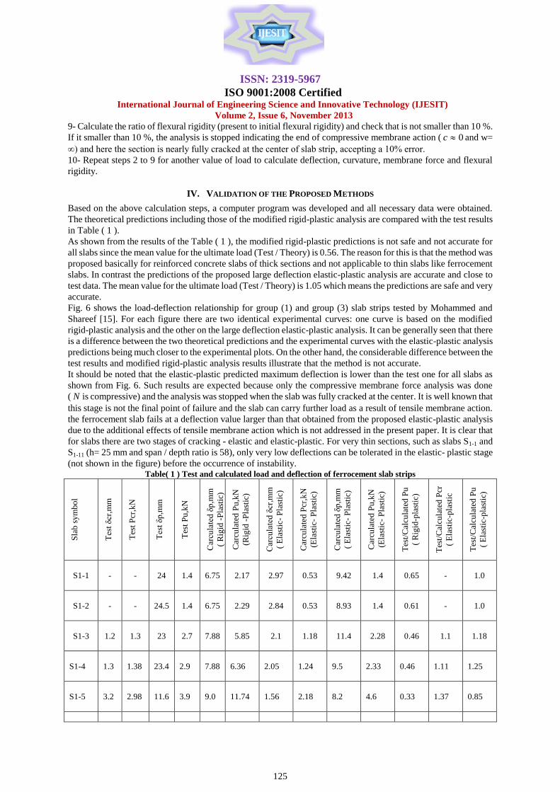
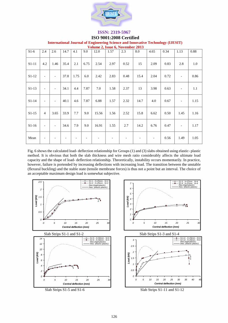
Fig. 6 shows the load-deflection relationship for group (1) and group (3) slab strips tested by Mohammed and
Shareef [15]. For each figure there are two identical experimental curves: one curve is based on the modified
rigid-plastic analysis and the other on the large deflection elastic-plastic analysis. It can be generally seen that there
is a difference between the two theoretical predictions and the experimental curves with the elastic-plastic analysis
predictions being much closer to the experimental plots. On the other hand, the considerable difference between the
test results and modified rigid-plastic analysis results illustrate that the method is not accurate.
It should be noted that the elastic-plastic predicted maximum deflection is lower than the test one for all slabs as
shown from Fig. 6. Such results are expected because only the compressive membrane force analysis was done
( N is compressive) and the analysis was stopped when the slab was fully cracked at the center. It is well known that
this stage is not the final point of failure and the slab can carry further load as a result of tensile membrane action.
the ferrocement slab fails at a deflection value larger than that obtained from the proposed elastic-plastic analysis
due to the additional effects of tensile membrane action which is not addressed in the present paper. It is clear that
for slabs there are two stages of cracking - elastic and elastic-plastic. For very thin sections, such as slabs S1-1 and
S1-11 (h= 25 mm and span / depth ratio is 58), only very low deflections can be tolerated in the elastic- plastic stage
(not shown in the figure) before the occurrence of instability. Table( 1 ) Test and calculated load and deflection of ferrocement slab strips
Sla
b s
ym
bo
l
Tes
t δcr
,mm
Tes
t P
cr,k
N
Tes
t δp
,mm
Tes
t P
u,k
N
Car
cula
ted
δp
,mm
( R
igid
-P
last
ic)
Car
cula
ted
Pu
,kN
(Rig
id -
Pla
stic
)
Car
cula
ted
δcr
,mm
( E
last
ic-
Pla
stic
)
Car
cula
ted
Pcr
,kN
(Ela
stic
- P
last
ic)
Car
cula
ted
δp
,mm
( E
last
ic-
Pla
stic
)
Car
cula
ted
Pu
,kN
(Ela
stic
- P
last
ic)
Tes
t/C
alcu
late
d P
u
( R
igid
-pla
stic
)
Tes
t/C
alcu
late
d P
cr
( E
last
ic-p
last
ic
Tes
t/C
alcu
late
d P
u
( E
last
ic-p
last
ic)
S1-1
-
-
24
1.4
6.75
2.17
2.97
0.53
9.42
1.4
0.65
-
1.0
S1-2
-
-
24.5
1.4
6.75
2.29
2.84
0.53
8.93
1.4
0.61
-
1.0
S1-3
1.2
1.3
23
2.7
7.88
5.85
2.1
1.18
11.4
2.28
0.46
1.1
1.18
S1-4
1.3
1.38
23.4
2.9
7.88
6.36
2.05
1.24
9.5
2.33
0.46
1.11
1.25
S1-5
3.2
2.98
11.6
3.9
9.0
11.74
1.56
2.18
8.2
4.6
0.33
1.37
0.85
ISSN: 2319-5967
ISO 9001:2008 Certified International Journal of Engineering Science and Innovative Technology (IJESIT)
Volume 2, Issue 6, November 2013
126
0
1
2
3
4
5
6
7
0 5 10 15 20 25 30
Central deflection (mm)
Lo
ad
(k
N)
S1-3 , h=37mm , N=4 S1-4 , h=37mm , N=4 theo.(rigid-plastic)theo. (elastic-plastic)
0
0.5
1
1.5
2
2.5
0 5 10 15 20 25 30
Central deflection (mm)
Lo
ad
(k
N)
S1-1 , h=25mm , N=3S1-2 , h=25mm , N=3 theo.(regid-plastic)theo. (elastic-plastic)
0
2
4
6
8
10
12
14
0 5 10 15 20 25 30
Central deflection (mm)
Lo
ad
(k
N)
S1-5 , h=50mm , N=5 S1-6 , h=50mm , N=5 theo.(rigid-plastic)theo. (elastic-plastic)
0
0.5
1
1.5
2
2.5
3
0 5 10 15 20 25 30 35 40 45
Central deflection (mm)
Lo
ad
(k
N)
S1-11 , h=25mm , N=6 S1-12 , h=25mm , N=6 theo.(rigid-plastic)theo. (elastic-plastic)
S1-6
2.4 2.6 14.7 4.1 9.0 12.0 1.57 2.3 8.0 4.65 0.34 1.13 0.88
S1-11
4.2
1.46
35.4
2.1
6.75
2.54
2.97
0.52
15
2.09
0.83
2.8
1.0
S1-12
-
-
37.8
1.75
6.0
2.42
2.83
0.48
15.4
2.04
0.72
-
0.86
S1-13
-
-
34.1
4.4
7.87
7.0
1.58
2.37
13
3.98
0.63
-
1.1
S1-14
-
-
40.1
4.6
7.87
6.88
1.57
2.32
14.7
4.0
0.67
-
1.15
S1-15
4
3.65
33.9
7.7
9.0
15.56
1.56
2.52
15.8
6.62
0.50
1.45
1.16
S1-16
-
-
34.6
7.9
9.0
16.91
1.55
2.7
14.2
6.76
0.47
-
1.17
Mean
-
-
-
-
-
-
-
-
-
-
0.56
1.49
1.05
Fig. 6 shows the calculated load- deflection relationship for Groups (1) and (3) slabs obtained using elastic- plastic
method. It is obvious that both the slab thickness and wire mesh ratio considerably affects the ultimate load
capacity and the shape of load- deflection relationship. Theoretically, instability occurs momentarily. In practice,
however, failure is portended by increasing deflections with increasing load. The transition between the unstable
(flexural buckling) and the stable state (tensile membrane forces) is thus not a point but an interval. The choice of
an acceptable maximum design load is somewhat subjective.
Slab Strips S1-1 and S1-2 Slab Strips S1-3 and S1-4
Slab Strips S1-5 and S1-6 Slab Strips S1-11 and S1-12

ISSN: 2319-5967
ISO 9001:2008 Certified International Journal of Engineering Science and Innovative Technology (IJESIT)
Volume 2, Issue 6, November 2013
127
0
1
2
3
4
5
6
7
8
0 5 10 15 20 25 30 35 40 45
Central deflection (mm)
Lo
ad
(k
N)
S1-13 , h=37mm , N=8 S1-14 , h=37mm , N=8theo.(rigid-plastic)theo. (elastic-plastic)
0
2
4
6
8
10
12
14
16
18
0 5 10 15 20 25 30 35 40
Central deflection (mm)
Lo
ad
(k
N)
S1-15 , h=50mm , N=10S1-16 , h=50mm , N=10theo.(rigid-plastic)theo. (elastic-plastic)
Slab Strips S1-13 and S1-14 Slab Strips S1-15 and S1-16
Fig. (6) Theoretical and Experimental Load-central deflection relationship of axially restrained ferrocement slab
strips
ACKNOWLEDGMENT
The material presented in this paper is a part of M.Sc. thesis undertaken by the second author to the Faculty of
Engineering, University of Duhok. Financial supports and efforts presented by the faculty are highly appreciated.
REFERENCES
[1] Ockleston, A.J., "Arching Action in Reinforced Concrete slabs", The Structural Engineer , London, England, Vol.36,
June 1958, PP. 197-201.
[2] Park, R., "The Ultimate Strength and Long-Term Behavior of Uniformly Loaded Two-Way Concrete Slabs with Partial
Lateral Restraint at All Edges", Magazine of Concrete Research, London, England, Vol.16, No.48, September 1964, PP.
139-152.
[3] Park, R. and Gamble, W.L., "Reinforced Concrete Slabs", John Wiley and Sons, New York, 1980, PP. 562-609.
[4] Janas, M., "Large Plastic Deformation of Reinforced Concrete Slabs", International Journal of Solids and Structures,
Vol.4, 1968, PP. 61-74.
[5] Robert, E.H., "Load Carrying Capacity of Slab Strip Restrained Against Longitudinal Expansion", Concrete, Vol.3, No.9,
September 1969, PP. 369-378.
[6] Desayi, P. and Kulkarni, A.B., "Load-Deflection Behavior of Restrained Reinforced Concrete slabs", Journal of the
Structural Division, ASCE, Vol.103, No.ST2, February 1977,PP. 405-419.
[7] Eyre, J.R., "Direct assessment of Safe Strengths of RC Slabs under Membrane Action", Journal of Structural Engineering,
Vol.123, No.10, October 1997, PP. 1331-1338.
[8] Eyre, J.R., "Direct assessment of Safe Strengths of RC Slabs under Membrane Action", Journal of Structural Engineering,
Vol.123, No.10, October 1997, PP. 1331-1338.
[9] Welch, R.W., "Compressive Membrane and Capacity Estimates in Laterally Edge Restrained Concrete One-Way Slabs",
Ph.D, Thesis, University of Illinois at Urbana-Champaign, 1999.
[10] Mansur, M.A., "Ultimate Strength Design of Ferrocement in Flexural", Journal of Ferrocement, Vol.18, No.4, October
1988, PP. 385-395.
[11] Shah, S.P. and Balaguru, P.N., "Ferrocement", in New Reinforced Concretes by R.N. Swamy, Bishopbriggs, Glasgow,
Survey University Press, 1984.
[12] Walraven, J.C. and Spierenburg, S.E.J., "Behavior of Ferrocement with Chicken Wire Mesh Reinforcement", Journal of
Ferrocement, Vol.15, No.1, January 1985.
[13] ACI 318M-05, "Building Code Requirements for Reinforced concrete", American Concrete Institute, 2005.
[14] Shareef, Yaman S. "Flexural Behavior of Axially Restrained One-Way Ferrocement Slabs", M.Sc. Thesis, University of
Duhok, 2008, pp. 110. ( Unpublished )
ISSN: 2319-5967
ISO 9001:2008 Certified International Journal of Engineering Science and Innovative Technology (IJESIT)
Volume 2, Issue 6, November 2013
128
[15] Mohammed, A.A and Shareef, Y.S.", Tests on Axially Restrained Ferrocement Slab Strips," Journal of Duhok University,
Vol.14 , No.1 ,2010, pp.138-155
AUTHOR BIOGRAPHY
Azad A. Mohammed is an Assistant Professor in Civil Engineering Department, Faculty of Engineering, University of
Sulaimani, Sulaimani, Iraq. He received B.Sc. degree in Civil Engineering, College of Engineering, University of Baghdad
in 1994, M.Sc. degree in Structural Engineering, Building Construction Department, University of Technology- Baghdad
in 1997 and Ph.D. in the same university in 2004. He published thirteen scientific papers. Dr. Mohammed’s research has
focused on strengthening concrete structures, ferrocement structures, membrane action in slabs and inelastic behavior of
concrete.
Yaman S. Shareef is a PhD candidate in the Faculty of Engineering & Industrial Sciences, Swinburne University of
Technology. He obtained B.Sc. degree in Civil Engineering, College of Engineering, University of Duhok in 2003 and
M.Sc. degree in Civil Engineering, College of Engineering, University of Duhok in 2008. His research has focused on
strengthening concrete structures and membrane action in slabs.