FlexRay Protocol Specification V3.0.1
341
FlexRay Communications System Protocol Specification Version 3.0.1
-
Upload
amine-fourati -
Category
Documents
-
view
1.256 -
download
26
Transcript of FlexRay Protocol Specification V3.0.1

FlexRay Communications System
Protocol Specification
Version 3.0.1

FlexRay Protocol Specification Disclaimer
DisclaimerThis specification and the material contained in it, as released by the FlexRay Consortium, is for the purposeof information only. The FlexRay Consortium and the companies that have contributed to it shall not be liablefor any use of the specification.
The material contained in this specification is protected by copyright and other types of Intellectual PropertyRights. The commercial exploitation of the material contained in this specification requires a license to suchIntellectual Property Rights.
This specification may be utilized or reproduced without any modification, in any form or by any means, forinformational purposes only.
For any other purpose, no part of the specification may be utilized or reproduced, in any form or by anymeans, without permission in writing from the publisher.
Important Information
1. The FlexRay™ specifications V2.1 and V3.0.1 and the corresponding FlexRay™Conformance Test specifications (hereinafter together "FlexRay™ specifications")have been developed for automotive applications only. They have neither beendeveloped nor tested for non-automotive applications.
2. The FlexRay™ specifications are retrievable on the FlexRay Websitewww.flexray.com for information purposes only and without obligation.
3. The technical expertise provided in the FlexRay™ specifications is subject to continu-ous further development. The FlexRay™ specifications serve exclusively as an infor-mation source to enable to manufacture and test products which comply with theFlexRay™ specifications ("FlexRay™ compliant products"). Observation of theFlexRay™ specifications does neither guarantee the operability and safety of theFlexRay™ compliant products, nor does it guarantee the safe cooperation of multipleFlexRay™ compliant products with each other or with other products. Therefore, themembers of the former FlexRay™ Consortium are not able to assume liability for theoperability and safety of such products and the safe cooperation of multipleFlexRay™ compliant products with each other or with other products.
4. The FlexRay™ specifications V3.0.1 were submitted to ISO in order to be publishedas a standard for road vehicles.
The word FlexRay and the FlexRay logo are registered trademarks.
Copyright © 2006 - 2010. All rights reserved.
The Core Partners of the FlexRay Consortium are Adam Opel GmbH, Bayerische Motoren Werke AG,Daimler AG, Freescale Halbleiter Deutschland GmbH, NXP B.V., Robert Bosch GmbH, and Volkswagen AG.
Version 3.0.1 October 2010 Page 2 of 341

FlexRay Protocol Specification Table of Contents
Table of Contents
Disclaimer..............................................................................................................................................2
Chapter 1Introduction.............................................................................................................. 12
1.1 Scope .............................................................................................................................................12 1.2 References .....................................................................................................................................12 1.2.1 FlexRay consortium documents ........................................................................................... 12 1.2.2 Non-consortium documents.................................................................................................. 12 1.3 Revision history ..............................................................................................................................13 1.4 Terms and definitions .....................................................................................................................16 1.5 Acronyms and abbreviations ..........................................................................................................22 1.6 Notational conventions ...................................................................................................................24 1.6.1 Parameter prefix conventions............................................................................................... 24 1.6.2 Color coding ......................................................................................................................... 25 1.6.3 Implementation dependent behavior .................................................................................... 25 1.7 SDL conventions ............................................................................................................................25 1.7.1 General................................................................................................................................. 25 1.7.2 SDL notational conventions.................................................................................................. 26 1.7.3 SDL extensions .................................................................................................................... 26 1.7.3.1 Microtick, macrotick and sample tick timers ................................................................. 26 1.7.3.2 Microtick behavior of the 'now' - expression ................................................................. 27 1.7.3.3 Channel-specific process replication ............................................................................ 27 1.7.3.4 Handling of priority input symbols................................................................................. 27 1.7.3.5 Signals to non-instantiated processes.......................................................................... 28 1.7.3.6 Exported and imported signals ..................................................................................... 28 1.8 Bit rates ..........................................................................................................................................28 1.9 Roles of a node in a FlexRay cluster..............................................................................................28 1.10 Synchronization methods .............................................................................................................29 1.10.1 TT-D synchronization method ............................................................................................ 29 1.10.2 TT-L synchronization method ............................................................................................. 29 1.10.3 TT-E synchronization method............................................................................................. 30 1.11 Network topology considerations..................................................................................................32 1.11.1 Passive bus topology.......................................................................................................... 33 1.11.2 Active star topology ............................................................................................................ 33 1.11.3 Active star topology combined with a passive bus topology............................................... 35 1.12 Example node architecture...........................................................................................................37 1.12.1 Objective............................................................................................................................. 37 1.12.2 Overview............................................................................................................................. 37 1.12.3 Host - communication controller interface .......................................................................... 37 1.12.4 Communication controller - bus driver interface ................................................................. 38 1.12.5 Bus driver - host interface................................................................................................... 39 1.12.5.1 Hard wired signals (option A) ..................................................................................... 39 1.12.5.2 Serial peripheral interface (SPI) (option B)................................................................. 39 1.12.6 Bus driver - power supply interface (optional) .................................................................... 40 1.12.7 Time gateway interface ...................................................................................................... 40 1.13 Testability requirements ...............................................................................................................40
Chapter 2Protocol Operation Control .................................................................................... 41
Version 3.0.1 October 2010 Page 3 of 341
FlexRay Protocol Specification Table of Contents
2.1 Principles ........................................................................................................................................41 2.1.1 Communication controller power moding ............................................................................. 41 2.2 Description......................................................................................................................................42 2.2.1 Operational overview............................................................................................................ 43 2.2.1.1 Host commands............................................................................................................ 44 2.2.1.2 Error conditions ............................................................................................................ 45 2.2.1.2.1 Errors causing immediate entry to the POC:halt state ..........................................45 2.2.1.2.2 Errors handled by the degradation model .............................................................45 2.2.1.3 POC status ................................................................................................................... 46 2.2.1.4 SDL considerations for single channel nodes .............................................................. 47 2.3 The protocol operation control process ..........................................................................................48 2.3.1 POC SDL utilities.................................................................................................................. 48 2.3.2 SDL organization .................................................................................................................. 50 2.3.3 Preempting commands......................................................................................................... 50 2.3.4 Deferred commands ............................................................................................................. 51 2.3.4.1 DEFERRED_HALT, DEFERRED_READY and CLEAR_DEFERRED commands ...... 51 2.3.4.2 ALL_SLOTS command................................................................................................. 54 2.3.5 Reaching the POC:ready state............................................................................................. 54 2.3.5.1 Default configuration requirements............................................................................... 56 2.3.6 Reaching the POC:normal active state ................................................................................ 57 2.3.6.1 Wakeup and startup support ........................................................................................ 58 2.3.7 Behavior during normal operation ........................................................................................ 60 2.3.7.1 Cyclical behavior .......................................................................................................... 60 2.3.7.1.1 Cycle counter.........................................................................................................60 2.3.7.1.2 POC:normal active state........................................................................................60 2.3.7.1.3 POC:normal passive state.....................................................................................62 2.3.7.1.4 Error checking during normal operation ................................................................64 2.3.7.1.4.1 Error checking overview ................................................................................65 2.3.7.1.4.2 Error checking details for the POC:normal active state.................................65 2.3.7.1.4.3 Error checking details for the POC:normal passive state ..............................66
Chapter 3Coding and Decoding ............................................................................................. 69
3.1 Principles ........................................................................................................................................69 3.2 Description......................................................................................................................................69 3.2.1 Frame and symbol encoding ................................................................................................ 70 3.2.1.1 Frame encoding............................................................................................................ 70 3.2.1.1.1 Transmission start sequence.................................................................................70 3.2.1.1.2 Frame start sequence............................................................................................71 3.2.1.1.3 Byte start sequence...............................................................................................71 3.2.1.1.4 Frame end sequence.............................................................................................71 3.2.1.1.5 Dynamic trailing sequence ....................................................................................71 3.2.1.1.6 Frame bit stream assembly ...................................................................................72 3.2.1.2 Symbol encoding .......................................................................................................... 73 3.2.1.2.1 Collision avoidance symbol and media access test symbol ..................................73 3.2.1.2.2 Wakeup symbol .....................................................................................................74 3.2.1.2.3 Wakeup During Operation Pattern (WUDOP) .......................................................77 3.2.2 Sampling and majority voting ............................................................................................... 77 3.2.3 Bit clock alignment and bit strobing ...................................................................................... 78 3.2.4 Implementation specific delays............................................................................................. 79 3.2.5 Channel idle detection .......................................................................................................... 80 3.2.6 Action point and time reference point ................................................................................... 80 3.2.7 Frame and symbol decoding ................................................................................................ 82
Version 3.0.1 October 2010 Page 4 of 341
FlexRay Protocol Specification Table of Contents
3.2.7.1 Frame decoding............................................................................................................ 83 3.2.7.2 Symbol decoding .......................................................................................................... 84 3.2.7.2.1 Collision avoidance symbol and media access test symbol decoding ..................84 3.2.7.2.2 Wakeup symbol decoding .....................................................................................84 3.2.7.3 Decoding error.............................................................................................................. 85 3.2.8 Signal integrity ...................................................................................................................... 86 3.3 Coding and decoding process ........................................................................................................86 3.3.1 Operating modes .................................................................................................................. 86 3.3.2 Coding and decoding process behavior ............................................................................... 86 3.3.3 Encoding behavior................................................................................................................ 88 3.3.4 Encoding macros.................................................................................................................. 91 3.3.5 Decoding behavior................................................................................................................ 96 3.3.6 Decoding macros.................................................................................................................. 97 3.4 Bit strobing process ......................................................................................................................104 3.4.1 Operating modes ................................................................................................................ 104 3.4.2 Bit strobing process behavior ............................................................................................. 105 3.5 Wakeup pattern decoding process ...............................................................................................107 3.5.1 Operating modes ................................................................................................................ 107 3.5.2 Wakeup pattern decoding process behavior ...................................................................... 108
Chapter 4Frame Format......................................................................................................... 111
4.1 Overview.......................................................................................................................................111 4.2 FlexRay header segment (5 bytes) ..............................................................................................111 4.2.1 Reserved bit (1 bit) ............................................................................................................. 111 4.2.2 Payload preamble indicator (1 bit)...................................................................................... 112 4.2.3 Null frame indicator (1 bit) .................................................................................................. 112 4.2.4 Sync frame indicator (1 bit)................................................................................................. 112 4.2.5 Startup frame indicator (1 bit) ............................................................................................. 113 4.2.6 Frame ID (11 bits)............................................................................................................... 113 4.2.7 Payload length (7 bits)........................................................................................................ 114 4.2.8 Header CRC (11 bits) ......................................................................................................... 114 4.2.9 Cycle count (6 bits)............................................................................................................. 115 4.2.10 Formal header definition................................................................................................... 115 4.3 FlexRay payload segment (0 - 254 bytes)....................................................................................115 4.3.1 NMVector............................................................................................................................ 116 4.3.2 Message ID (16 bits) .......................................................................................................... 117 4.4 FlexRay trailer segment................................................................................................................117 4.5 CRC calculation details ................................................................................................................118 4.5.1 CRC calculation algorithm .................................................................................................. 118 4.5.2 Header CRC calculation ..................................................................................................... 119 4.5.3 Frame CRC calculation ...................................................................................................... 119
Chapter 5Media Access Control ........................................................................................... 121
5.1 Principles ......................................................................................................................................121 5.1.1 Communication cycle ......................................................................................................... 121 5.1.2 Communication cycle execution ......................................................................................... 122 5.1.3 Static segment.................................................................................................................... 123 5.1.3.1 Structure of the static segment................................................................................... 123 5.1.3.2 Execution and timing of the static segment ................................................................ 123 5.1.4 Dynamic segment............................................................................................................... 124
Version 3.0.1 October 2010 Page 5 of 341

FlexRay Protocol Specification Table of Contents
5.1.4.1 Structure of the dynamic segment.............................................................................. 124 5.1.4.2 Execution and timing of the dynamic segment ........................................................... 125 5.1.5 Symbol window................................................................................................................... 128 5.1.6 Network idle time ................................................................................................................ 129 5.2 Description....................................................................................................................................129 5.2.1 Operating modes ................................................................................................................ 130 5.2.2 Significant events ............................................................................................................... 131 5.2.2.1 Reception-related events............................................................................................ 131 5.2.2.2 Transmission-related events ...................................................................................... 132 5.2.2.3 Timing-related events ................................................................................................. 132 5.3 Media access control process ......................................................................................................132 5.3.1 Initialization and MAC:standby state .................................................................................. 133 5.3.2 Static segment related states ............................................................................................. 135 5.3.2.1 State machine for the static segment media access control ...................................... 135 5.3.2.2 Transmission conditions and frame assembly in the static segment.......................... 137 5.3.3 Dynamic segment related states ........................................................................................ 140 5.3.3.1 State machine for the dynamic segment media access control ................................. 140 5.3.3.2 Transmission conditions and frame assembly in the dynamic segment..................... 145 5.3.4 Symbol window related states ............................................................................................ 146 5.3.5 Network idle time ................................................................................................................ 147
Chapter 6Frame and Symbol Processing ............................................................................ 149
6.1 Principles ......................................................................................................................................149 6.2 Description....................................................................................................................................149 6.2.1 Operating modes ................................................................................................................ 150 6.2.2 Significant events ............................................................................................................... 151 6.2.2.1 Reception-related events............................................................................................ 151 6.2.2.2 Decoding-related events............................................................................................. 152 6.2.2.3 Timing-related events ................................................................................................. 152 6.2.3 Status data ......................................................................................................................... 153 6.3 Frame and symbol processing process........................................................................................155 6.3.1 Initialization and FSP:standby state ................................................................................... 156 6.3.2 Macro SLOT_SEGMENT_END.......................................................................................... 157 6.3.3 FSP:wait for CE start state ................................................................................................. 158 6.3.4 FSP:decoding in progress state ......................................................................................... 159 6.3.4.1 Frame reception checks during non-synchronized operation..................................... 161 6.3.4.2 Frame reception checks during synchronized operation ............................................ 162 6.3.4.2.1 Frame reception checks in the static segment ....................................................162 6.3.4.2.2 Frame reception checks in the dynamic segment ...............................................163 6.3.5 FSP:wait for CHIRP state ................................................................................................... 164 6.3.6 FSP:wait for transmission end state ................................................................................... 165
Chapter 7Wakeup and Startup.............................................................................................. 167
7.1 Cluster wakeup.............................................................................................................................167 7.1.1 Principles ............................................................................................................................ 167 7.1.2 Description.......................................................................................................................... 168 7.1.3 Wakeup support by the communication controller.............................................................. 169 7.1.3.1 Wakeup state diagram................................................................................................ 170 7.1.3.2 The POC:wakeup listen state ..................................................................................... 171 7.1.3.3 The POC:wakeup send state...................................................................................... 172
Version 3.0.1 October 2010 Page 6 of 341

FlexRay Protocol Specification Table of Contents
7.1.3.4 The POC:wakeup detect state.................................................................................... 173 7.2 Communication startup and reintegration.....................................................................................173 7.2.1 Principles ............................................................................................................................ 173 7.2.1.1 Definition and properties............................................................................................. 173 7.2.1.2 Principle of operation.................................................................................................. 174 7.2.1.2.1 Startup performed by the coldstart nodes ...........................................................174 7.2.1.2.2 Integration of the non-coldstart nodes .................................................................174 7.2.2 Description.......................................................................................................................... 175 7.2.3 Coldstart inhibit mode......................................................................................................... 175 7.2.4 Startup state diagram ......................................................................................................... 176 7.2.4.1 Path of a TT-D leading coldstart node........................................................................ 179 7.2.4.2 Path of a TT-D following coldstart node ..................................................................... 179 7.2.4.3 Path of a TT-L coldstart node ..................................................................................... 180 7.2.4.4 Path of a TT-E coldstart node..................................................................................... 180 7.2.4.5 Path of a non-coldstart node ...................................................................................... 183 7.2.4.6 The POC:coldstart listen state.................................................................................... 184 7.2.4.7 The POC:coldstart collision resolution state............................................................... 186 7.2.4.8 The POC:coldstart consistency check state ............................................................... 187 7.2.4.9 The POC:coldstart gap state ...................................................................................... 188 7.2.4.10 The POC:initialize schedule state............................................................................. 189 7.2.4.11 The POC:integration coldstart check state ............................................................... 190 7.2.4.12 The POC:coldstart join state..................................................................................... 191 7.2.4.13 The POC:integration listen state............................................................................... 192 7.2.4.14 The POC:integration consistency check state.......................................................... 193
Chapter 8Clock Synchronization.......................................................................................... 195
8.1 Introduction...................................................................................................................................195 8.2 Time representation......................................................................................................................196 8.2.1 Timing hierarchy ................................................................................................................. 196 8.2.2 Global and local time .......................................................................................................... 197 8.2.3 Parameters and variables................................................................................................... 197 8.3 Synchronization process ..............................................................................................................198 8.4 Startup of the clock synchronization.............................................................................................204 8.4.1 Coldstart startup ................................................................................................................. 206 8.4.2 Integration startup............................................................................................................... 206 8.5 Time measurement.......................................................................................................................209 8.5.1 Data structure ..................................................................................................................... 209 8.5.2 Initialization......................................................................................................................... 210 8.5.3 Time measurement storage................................................................................................ 211 8.6 Correction term calculation...........................................................................................................213 8.6.1 Fault-tolerant midpoint algorithm ........................................................................................ 213 8.6.2 Calculation of the offset correction value............................................................................ 214 8.6.3 Calculation of the rate correction value .............................................................................. 217 8.6.4 Value limitations ................................................................................................................. 219 8.6.5 Host-controlled external clock synchronization .................................................................. 220 8.6.6 TT-E time gateway sink correction determination .............................................................. 220 8.7 Clock correction............................................................................................................................226 8.8 Sync frame configuration rules .....................................................................................................229 8.8.1 TT-D cluster........................................................................................................................ 230 8.8.2 TT-E cluster ........................................................................................................................ 230 8.8.3 TT-L cluster ........................................................................................................................ 230 8.9 Time gateway interface ................................................................................................................231
Version 3.0.1 October 2010 Page 7 of 341

FlexRay Protocol Specification Table of Contents
Chapter 9Controller Host Interface ...................................................................................... 232
9.1 Principles ......................................................................................................................................232 9.2 Description....................................................................................................................................232 9.3 Interfaces......................................................................................................................................233 9.3.1 Protocol data interface........................................................................................................ 233 9.3.1.1 Protocol configuration data......................................................................................... 233 9.3.1.1.1 Communication cycle timing configuration ..........................................................234 9.3.1.1.2 Protocol operation configuration..........................................................................234 9.3.1.1.3 Wakeup and startup configuration.......................................................................236 9.3.1.1.4 Network Management Vector configuration ........................................................237 9.3.1.2 Protocol control data................................................................................................... 237 9.3.1.2.1 Control of the protocol operation control .............................................................237 9.3.1.2.2 Control of MTS and WUDOP transmission .........................................................237 9.3.1.2.3 Control of external clock synchronization ............................................................238 9.3.1.3 Protocol status data.................................................................................................... 239 9.3.1.3.1 Protocol operation control status .........................................................................239 9.3.1.3.2 Wakeup and startup status..................................................................................239 9.3.1.3.3 Communication cycle timing status .....................................................................240 9.3.1.3.4 Synchronization frame status ..............................................................................241 9.3.1.3.5 Startup frame status ............................................................................................241 9.3.1.3.6 Symbol window status .........................................................................................241 9.3.1.3.7 NIT status ............................................................................................................242 9.3.1.3.8 Aggregated channel status..................................................................................242 9.3.1.3.9 Dynamic segment status .....................................................................................243 9.3.2 Message data interface ...................................................................................................... 243 9.3.2.1 Communication slot assignment................................................................................. 244 9.3.2.2 Communication slot assignment for transmission ...................................................... 244 9.3.2.2.1 Cycle-independent and cycle-dependent slot assignment ..................................244 9.3.2.2.2 Transmission slot assignment list........................................................................245 9.3.2.2.3 Key slot assignment ............................................................................................245 9.3.2.3 Communication slot assignment for reception............................................................ 246 9.3.2.4 Conflicting communication slot assignment for reception and transmission .............. 246 9.3.2.5 Non-queued message buffers .................................................................................... 246 9.3.2.5.1 Message buffer configuration data ......................................................................246 9.3.2.5.2 Message buffer status data .................................................................................247 9.3.2.5.3 Message buffer payload data and payload data valid flag ..................................248 9.3.2.5.4 Buffer Enabling and Buffer Locking .....................................................................249 9.3.2.6 Non-queued message buffer identification ................................................................. 249 9.3.2.6.1 Candidate transmit message buffer identification................................................249 9.3.2.6.2 Candidate receive message buffer identification.................................................250 9.3.2.6.3 Selected transmit buffer identification..................................................................251 9.3.2.6.4 Selected receive buffer identification...................................................................251 9.3.2.6.5 Active message buffer identification ....................................................................251 9.3.2.7 Message transmission................................................................................................ 251 9.3.2.7.1 Transmit buffer configuration...............................................................................251 9.3.2.7.2 Transmit buffer identification for message retrieval.............................................252 9.3.2.7.3 Transmit buffer status..........................................................................................253 9.3.2.8 Message reception ..................................................................................................... 254 9.3.2.8.1 Non-queued receive buffer configuration ............................................................254 9.3.2.8.2 Non-queued receive buffer contents ...................................................................256 9.3.2.8.2.1 Slot status data............................................................................................256 9.3.2.8.2.2 Frame contents data....................................................................................257
Version 3.0.1 October 2010 Page 8 of 341
FlexRay Protocol Specification Table of Contents
9.3.2.9 Non-queued message buffer status update ............................................................... 258 9.3.2.10 Queued receive buffers (FIFO's) .............................................................................. 259 9.3.2.10.1 Basic FIFO behavior..........................................................................................259 9.3.2.10.1.1 Admittance into a FIFO..............................................................................260 9.3.2.10.1.2 Reading and removal from a FIFO ............................................................261 9.3.2.10.2 FIFO admittance criteria ....................................................................................261 9.3.2.10.2.1 FIFO frame validity admittance criteria......................................................262 9.3.2.10.2.2 FIFO channel admittance criteria ..............................................................262 9.3.2.10.2.3 FIFO frame identifier admittance criteria ...................................................263 9.3.2.10.2.4 FIFO cycle counter admittance criteria......................................................263 9.3.2.10.2.5 Message identifier admittance criteria .......................................................264 9.3.2.10.3 FIFO performance requirements .......................................................................264 9.3.2.10.4 FIFO status information .....................................................................................265 9.3.3 CHI Services....................................................................................................................... 266 9.3.3.1 Macrotick timer service............................................................................................... 266 9.3.3.2 Interrupt service.......................................................................................................... 266 9.3.3.3 Message ID filtering service ....................................................................................... 267 9.3.3.4 Network management service .................................................................................... 267
Appendix ASystem Parameters ............................................................................................... 269
A.1 Protocol constants........................................................................................................................269 A.2 Performance constants ................................................................................................................271
Appendix BConfiguration Constraints .................................................................................... 272
B.1 General ........................................................................................................................................272 B.2 Bit rates ........................................................................................................................................272 B.3 Parameters...................................................................................................................................273 B.3.1 Global cluster parameters ...................................................................................................273 B.3.1.1 Protocol relevant .........................................................................................................273 B.3.1.2 Protocol related ...........................................................................................................274 B.3.2 Node parameters ................................................................................................................275 B.3.2.1 Protocol relevant .........................................................................................................275 B.3.2.2 Protocol related ...........................................................................................................278 B.3.3 Physical layer parameters...................................................................................................278 B.3.4 Auxiliary parameters ...........................................................................................................281 B.4 Calculation of configuration parameters for nodes in a TT-D cluster ...........................................283 B.4.1 gClockDeviationMax ...........................................................................................................283 B.4.2 Attainable precision.............................................................................................................284 B.4.2.1 Propagation Delay.......................................................................................................284 B.4.2.1.1 adInternalRxDelay...............................................................................................284 B.4.2.1.2 adPropagationDelayMax.....................................................................................284 B.4.2.1.3 adPropagationDelayMin......................................................................................286 B.4.2.2 Microtick Distribution Error ..........................................................................................288 B.4.2.3 Worst-case precision...................................................................................................289 B.4.2.4 Best-case precision.....................................................................................................289 B.4.2.5 Assumed precision......................................................................................................290 B.4.3 Ringing ................................................................................................................................290 B.4.4 Definition of microtick, macrotick, and bit time ....................................................................291 B.4.5 adInitializationErrorMax.......................................................................................................293 B.4.6 pdAcceptedStartupRange ...................................................................................................294
Version 3.0.1 October 2010 Page 9 of 341
FlexRay Protocol Specification Table of Contents
B.4.7 pClusterDriftDamping..........................................................................................................294 B.4.8 gdActionPointOffset ............................................................................................................295 B.4.9 gdMinislotActionPointOffset ................................................................................................296 B.4.10 gdSymbolWindowActionPointOffset..................................................................................296 B.4.11 gdMinislot ..........................................................................................................................297 B.4.12 gdStaticSlot .......................................................................................................................298 B.4.13 gdSymbolWindow .............................................................................................................300 B.4.14 gMacroPerCycle................................................................................................................302 B.4.15 pMicroPerCycle.................................................................................................................303 B.4.16 gdDynamicSlotIdlePhase ..................................................................................................304 B.4.17 gNumberOfMinislots..........................................................................................................305 B.4.18 pRateCorrectionOut ..........................................................................................................306 B.4.19 Offset Correction ...............................................................................................................307 B.4.19.1 aOffsetCorrectionMax ...............................................................................................307 B.4.19.2 pOffsetCorrectionOut ................................................................................................309 B.4.20 pOffsetCorrectionStart ......................................................................................................310 B.4.21 gdNIT ................................................................................................................................310 B.4.22 pExternRateCorrection......................................................................................................312 B.4.23 pExternOffsetCorrection....................................................................................................313 B.4.24 pdListenTimeout................................................................................................................314 B.4.25 pDecodingCorrection ........................................................................................................314 B.4.26 pDelayCompensation........................................................................................................315 B.4.27 pMacroInitialOffset ............................................................................................................316 B.4.28 pMicroInitialOffset .............................................................................................................316 B.4.29 pLatestTx ..........................................................................................................................317 B.4.30 gdTSSTransmitter .............................................................................................................318 B.4.31 gdCASRxLowMax .............................................................................................................320 B.4.32 gdWakeupTxIdle ...............................................................................................................320 B.4.33 gdWakeupTxActive ...........................................................................................................321 B.4.34 gdWakeupRxIdle...............................................................................................................321 B.4.35 gdWakeupRxLow ..............................................................................................................322 B.4.36 gdWakeupRxWindow........................................................................................................322 B.4.37 gdIgnoreAfterTx ................................................................................................................322 B.4.38 pKeySlotID ........................................................................................................................325 B.4.39 adTxMax ...........................................................................................................................325 B.4.40 gPayloadLengthStatic .......................................................................................................325 B.4.41 pPayloadLengthDynMax ...................................................................................................326 B.4.42 gCycleCountMax...............................................................................................................326 B.5 Configuration of cluster synchronization method and node synchronization role ........................327 B.6 Calculation of configuration parameters for nodes in a TT-L cluster............................................327 B.6.1 gClusterDriftDamping..........................................................................................................327 B.6.2 TT-L cluster precision..........................................................................................................328 B.6.3 pSecondKeySlotID ..............................................................................................................328 B.6.4 gdActionPointOffset ............................................................................................................328 B.7 Calculation of configuration parameters for nodes in a TT-E cluster ...........................................328 B.7.1 gClusterDriftDamping..........................................................................................................329 B.7.2 TT-E cluster precision .........................................................................................................329 B.7.2.1 TT-E cluster precision for a TT-D worst-case precision time source cluster...............330 B.7.2.2 TT-E cluster precision for a TT-L time source cluster .................................................331 B.7.2.3 TT-E assumed precision .............................................................................................331 B.7.3 pSecondKeySlotID ..............................................................................................................332 B.7.4 Host-controlled external clock correction ............................................................................332 B.7.5 gdActionPointOffset ............................................................................................................332
Version 3.0.1 October 2010 Page 10 of 341
FlexRay Protocol Specification Table of Contents
B.7.6 gMacroPerCycle..................................................................................................................333 B.7.7 gdMacrotick.........................................................................................................................333 B.7.8 aOffsetCorrectionMax .........................................................................................................333 B.7.9 pOffsetCorrectionStart ........................................................................................................333 B.7.10 gdNIT ................................................................................................................................333 B.7.11 pdMicrotick ........................................................................................................................333 B.7.12 adInitializationErrorMax.....................................................................................................334 B.7.13 pdAcceptedStartupRange .................................................................................................334 B.7.14 gCycleCountMax...............................................................................................................335
Appendix CWakeup Application Notes ................................................................................... 336
C.1 Wakeup initiation by the host .......................................................................................................336 C.1.1 Single-channel nodes .........................................................................................................336 C.1.2 Dual-channel nodes ............................................................................................................337 C.1.2.1 Wakeup pattern reception by the bus driver ...............................................................337 C.1.2.2 Wakeup pattern reception by the communication controller .......................................338 C.2 Host reactions to status flags signaled by the communication controller.....................................339 C.2.1 Frame header reception without decoding error .................................................................339 C.2.2 Wakeup pattern reception...................................................................................................339 C.2.3 Wakeup pattern transmission .............................................................................................339 C.2.4 Termination due to unsuccessful wakeup pattern transmission .........................................339 C.3 Retransmission of wakeup patterns.............................................................................................340 C.4 Transition to startup .....................................................................................................................340 C.5 Wakeup during operation.............................................................................................................340 C.5.1 Principles ............................................................................................................................340 C.5.1.1 Frame-based wakeup during operation ......................................................................341 C.5.1.2 Pattern-based wakeup during operation .....................................................................341
Version 3.0.1 October 2010 Page 11 of 341

FlexRay Protocol Specification Chapter 1: Introduction
Chapter 1Introduction
1.1 ScopeThe FlexRay communication protocol described in this document is specified for a dependable automotivenetwork. Some of the basic characteristics of the FlexRay protocol are synchronous and asynchronousframe transfer, guaranteed frame latency and jitter during synchronous transfer, prioritization of framesduring asynchronous transfer, single or multi-master clock synchronization1, time synchronization acrossmultiple networks, error detection and signaling, and scalable fault tolerance2.
1.2 References1.2.1 FlexRay consortium documents[EPL10] FlexRay Communications System - Electrical Physical Layer Specification, v3.0.1, FlexRay
Consortium, October 2010.
[EPLAN10] FlexRay Communications System - Electrical Physical Layer Application Notes, v3.0.1,FlexRay Consortium, October 2010.
[PCT10] FlexRay Communications System - Protocol Conformance Test Specification, v3.0.1, FlexRayConsortium, October 2010.
1.2.2 Non-consortium documents[Cas93] G. Castagnoli, S. Bräuer, and M. Herrmann, "Optimization of Cyclic Redundancy-Check Codes
with 24 and 32 Parity Bits", IEEE Transactions on Communications, vol. 41, pp. 883-892, June1993.
[Koo02] P. Koopman, "32-bit Cyclic Redundancy Codes for Internet Applications", Proceedings of theInternational Conference on Dependable Systems and Networks (DSN 2002), Washington DC,pp. 459-468. June 2002.
[Ung09] J. Ungermann, “On Clock Precision Of FlexRay Communication Systems”, Dec. 2009,available at: http://www.flexray.com
[Wad01] T. Wadayama, “Average Distortion of Some Cyclic Codes”, web site available at: http://www-tkm.ics.nitech.ac.jp/~wadayama/distortion.html
[Wel88] J. L. Welch and N. A. Lynch, "A New Fault-Tolerant Algorithm for Clock Synchronization", Infor-mation and Computation, vol. 77, no. 1, pp. 1-36, April 1988.
[Z100] ITU-T Recommendation Z.100 (03/93), Programming Languages - CCITT Specification andDescription Language (SDL), International Telecommunication Union, Geneva, 1993.
1 Multi-master clock synchronization refers to a synchronization that is based on the clocks of several (two or more) synchronization masters or sync nodes.
2 Scalable fault tolerance refers to the ability of the FlexRay protocol to operate in configurations that provide various degrees of fault tolerance (for example, single or dual channel clusters, clusters with many or few sync nodes, etc.).
Version 3.0.1 October 2010 Page 12 of 341
FlexRay Protocol Specification Chapter 1: Introduction
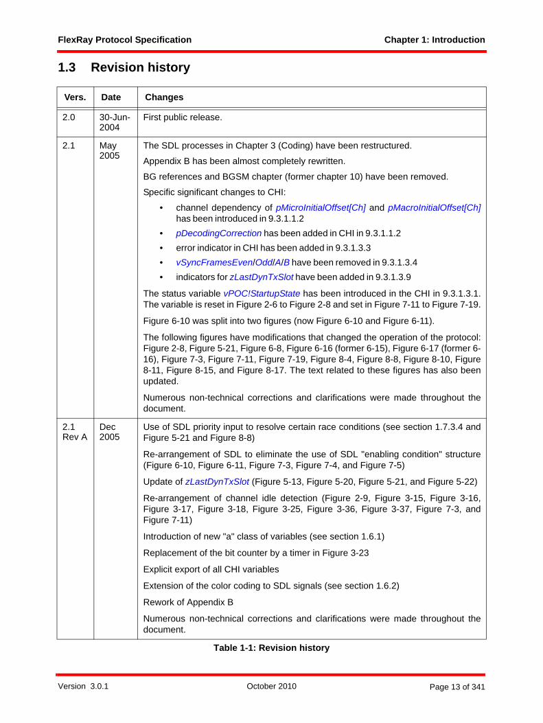
1.3 Revision history
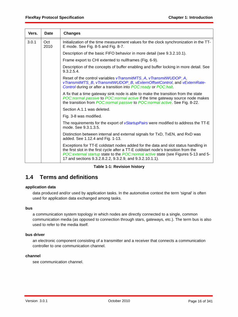
Vers. Date Changes
2.0 30-Jun-2004
First public release.
2.1 May 2005
The SDL processes in Chapter 3 (Coding) have been restructured.
Appendix B has been almost completely rewritten.
BG references and BGSM chapter (former chapter 10) have been removed.
Specific significant changes to CHI:
• channel dependency of pMicroInitialOffset[Ch] and pMacroInitialOffset[Ch]has been introduced in 9.3.1.1.2
• pDecodingCorrection has been added in CHI in 9.3.1.1.2• error indicator in CHI has been added in 9.3.1.3.3• vSyncFramesEven/Odd/A/B have been removed in 9.3.1.3.4• indicators for zLastDynTxSlot have been added in 9.3.1.3.9
The status variable vPOC!StartupState has been introduced in the CHI in 9.3.1.3.1.The variable is reset in Figure 2-6 to Figure 2-8 and set in Figure 7-11 to Figure 7-19.
Figure 6-10 was split into two figures (now Figure 6-10 and Figure 6-11).
The following figures have modifications that changed the operation of the protocol:Figure 2-8, Figure 5-21, Figure 6-8, Figure 6-16 (former 6-15), Figure 6-17 (former 6-16), Figure 7-3, Figure 7-11, Figure 7-19, Figure 8-4, Figure 8-8, Figure 8-10, Figure8-11, Figure 8-15, and Figure 8-17. The text related to these figures has also beenupdated.
Numerous non-technical corrections and clarifications were made throughout thedocument.
2.1Rev A
Dec2005
Use of SDL priority input to resolve certain race conditions (see section 1.7.3.4 andFigure 5-21 and Figure 8-8)
Re-arrangement of SDL to eliminate the use of SDL "enabling condition" structure(Figure 6-10, Figure 6-11, Figure 7-3, Figure 7-4, and Figure 7-5)
Update of zLastDynTxSlot (Figure 5-13, Figure 5-20, Figure 5-21, and Figure 5-22)
Re-arrangement of channel idle detection (Figure 2-9, Figure 3-15, Figure 3-16,Figure 3-17, Figure 3-18, Figure 3-25, Figure 3-36, Figure 3-37, Figure 7-3, andFigure 7-11)
Introduction of new "a" class of variables (see section 1.6.1)
Replacement of the bit counter by a timer in Figure 3-23
Explicit export of all CHI variables
Extension of the color coding to SDL signals (see section 1.6.2)
Rework of Appendix B
Numerous non-technical corrections and clarifications were made throughout thedocument.
Table 1-1: Revision history
Version 3.0.1 October 2010 Page 13 of 341
FlexRay Protocol Specification Chapter 1: Introduction
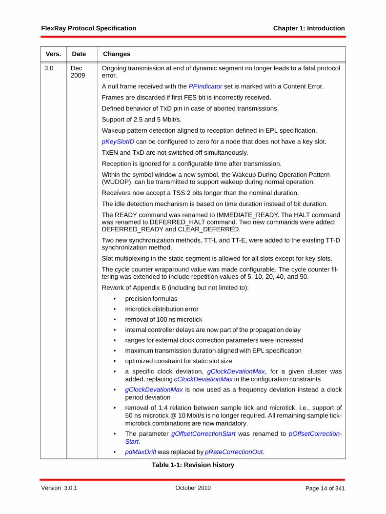
3.0 Dec 2009
Ongoing transmission at end of dynamic segment no longer leads to a fatal protocol error.
A null frame received with the PPIndicator set is marked with a Content Error.
Frames are discarded if first FES bit is incorrectly received.
Defined behavior of TxD pin in case of aborted transmissions.
Support of 2.5 and 5 Mbit/s.
Wakeup pattern detection aligned to reception defined in EPL specification.
pKeySlotID can be configured to zero for a node that does not have a key slot.
TxEN and TxD are not switched off simultaneously.
Reception is ignored for a configurable time after transmission.
Within the symbol window a new symbol, the Wakeup During Operation Pattern (WUDOP), can be transmitted to support wakeup during normal operation.
Receivers now accept a TSS 2 bits longer than the nominal duration.
The idle detection mechanism is based on time duration instead of bit duration.
The READY command was renamed to IMMEDIATE_READY. The HALT command was renamed to DEFERRED_HALT command. Two new commands were added: DEFERRED_READY and CLEAR_DEFERRED.
Two new synchronization methods, TT-L and TT-E, were added to the existing TT-D synchronization method.
Slot multiplexing in the static segment is allowed for all slots except for key slots.
The cycle counter wraparound value was made configurable. The cycle counter fil-tering was extended to include repetition values of 5, 10, 20, 40, and 50.
Rework of Appendix B (including but not limited to):
• precision formulas• microtick distribution error• removal of 100 ns microtick• internal controller delays are now part of the propagation delay• ranges for external clock correction parameters were increased• maximum transmission duration aligned with EPL specification• optimized constraint for static slot size• a specific clock deviation, gClockDevationMax, for a given cluster was
added, replacing cClockDeviationMax in the configuration constraints• gClockDevationMax is now used as a frequency deviation instead a clock
period deviation• removal of 1:4 relation between sample tick and microtick, i.e., support of
50 ns microtick @ 10 Mbit/s is no longer required. All remaining sample tick-microtick combinations are now mandatory.
• The parameter gOffsetCorrectionStart was renamed to pOffsetCorrection-Start.
• pdMaxDrift was replaced by pRateCorrectionOut.
Vers. Date Changes
Table 1-1: Revision history
Version 3.0.1 October 2010 Page 14 of 341
FlexRay Protocol Specification Chapter 1: Introduction
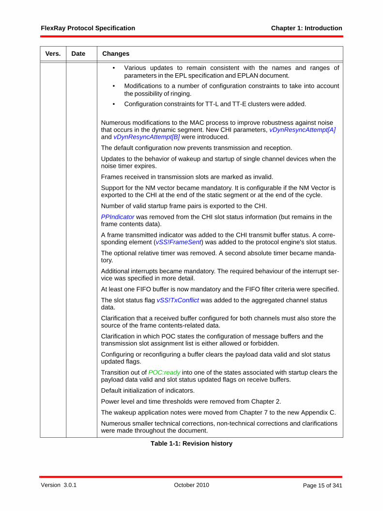
• Various updates to remain consistent with the names and ranges ofparameters in the EPL specification and EPLAN document.
• Modifications to a number of configuration constraints to take into accountthe possibility of ringing.
• Configuration constraints for TT-L and TT-E clusters were added.
Numerous modifications to the MAC process to improve robustness against noise that occurs in the dynamic segment. New CHI parameters, vDynResyncAttempt[A] and vDynResyncAttempt[B] were introduced.
The default configuration now prevents transmission and reception.
Updates to the behavior of wakeup and startup of single channel devices when the noise timer expires.
Frames received in transmission slots are marked as invalid.
Support for the NM vector became mandatory. It is configurable if the NM Vector is exported to the CHI at the end of the static segment or at the end of the cycle.
Number of valid startup frame pairs is exported to the CHI.
PPIndicator was removed from the CHI slot status information (but remains in the frame contents data).
A frame transmitted indicator was added to the CHI transmit buffer status. A corre-sponding element (vSS!FrameSent) was added to the protocol engine's slot status.
The optional relative timer was removed. A second absolute timer became manda-tory.
Additional interrupts became mandatory. The required behaviour of the interrupt ser-vice was specified in more detail.
At least one FIFO buffer is now mandatory and the FIFO filter criteria were specified.
The slot status flag vSS!TxConflict was added to the aggregated channel status data.
Clarification that a received buffer configured for both channels must also store the source of the frame contents-related data.
Clarification in which POC states the configuration of message buffers and the transmission slot assignment list is either allowed or forbidden.
Configuring or reconfiguring a buffer clears the payload data valid and slot status updated flags.
Transition out of POC:ready into one of the states associated with startup clears the payload data valid and slot status updated flags on receive buffers.
Default initialization of indicators.
Power level and time thresholds were removed from Chapter 2.
The wakeup application notes were moved from Chapter 7 to the new Appendix C.
Numerous smaller technical corrections, non-technical corrections and clarifications were made throughout the document.
Vers. Date Changes
Table 1-1: Revision history
Version 3.0.1 October 2010 Page 15 of 341
FlexRay Protocol Specification Chapter 1: Introduction
1.4 Terms and definitionsapplication data
data produced and/or used by application tasks. In the automotive context the term 'signal' is often used for application data exchanged among tasks.
busa communication system topology in which nodes are directly connected to a single, common communication media (as opposed to connection through stars, gateways, etc.). The term bus is also used to refer to the media itself.
bus driveran electronic component consisting of a transmitter and a receiver that connects a communication controller to one communication channel.
channelsee communication channel.
3.0.1 Oct 2010
Initialization of the time measurement values for the clock synchronization in the TT-E mode. See Fig. 8-5 and Fig. 8-7.
Description of the basic FIFO behavior in more detail (see 9.3.2.10.1).
Frame export to CHI extented to nullframes (Fig. 6-9).
Description of the concepts of buffer enabling and buffer locking in more detail. See 9.3.2.5.4.
Reset of the control variables vTransmitMTS_A, vTransmitWUDOP_A, vTransmitMTS_B, vTransmitWUDOP_B, vExternOffsetControl, and vExternRate-Control during or after a transition into POC:ready or POC:halt.
A fix that a time gateway sink node is able to make the transition from the state POC:normal passive to POC:normal active if the time gateway source node makes the transition from POC:normal passive to POC:normal active. See Fig. 8-22.
Section A.1.1 was deleted.
Fig. 3-8 was modified.
The requirements for the export of vStartupPairs were modified to address the TT-E mode. See 9.3.1.3.5.
Distinction between internal and external signals for TxD, TxEN, and RxD was added. See 1.12.4 and Fig. 1-13.
Exceptions for TT-E coldstart nodes added for the data and slot status handling in the first slot in the first cycle after a TT-E coldstart node's transition from the POC:external startup state to the POC:normal active state (see Figures 5-13 and 5-17 and sections 9.3.2.8.2.2, 9.3.2.9, and 9.3.2.10.1.1).
Vers. Date Changes
Table 1-1: Revision history
Version 3.0.1 October 2010 Page 16 of 341

FlexRay Protocol Specification Chapter 1: Introduction
channel idlethe condition on the physical transmission medium when no node is transmitting, as perceived by each individual node in the network. Note that detection of channel idle occurs some time after all nodes have actually stopped transmitting (due to idle detection times, channel effects, ringing, etc.).
cliqueset of communication controllers having the same view of certain systems properties, e.g., the global time value or the activity state of communication controllers.
clustera communication system of multiple nodes connected via at least one communication channel directly (bus topology), by active stars (star topology) or by a combination of bus and star connections (hybrid topologies).
coldstart nodea node capable of initiating the communication startup procedure on the cluster by sending startup frames. TT-D coldstart nodes, TT-L coldstart nodes, and TT-E coldstart nodes are all considered to be coldstart nodes. By definition, all coldstart nodes are also sync nodes.
communication channelthe inter-node connection through which signals are conveyed for the purpose of communication. The communication channel abstracts both the network topology (bus, star or hybrid), as well as the physical transmission medium.
communication controller (CC)an electronic component in a node that is responsible for implementing the protocol aspects of the FlexRay communications system.
communication cycleone complete instance of the communication structure that is periodically repeated to comprise the media access method of the FlexRay system. The communication cycle consists of a static segment, an optional dynamic segment, an optional symbol window, and a network idle time.
communication slotan interval of time during which access to a communication channel is granted exclusively to a specific node for the transmission of a frame with a frame ID corresponding to the slot. FlexRay distinguishes between static communication slots and dynamic communication slots.
cycle-dependent slot assignmentmethod of assigning, for a given channel, an individual slot (identified by a specific slot number and a specific cycle counter number) or a set of slots (identified by a specific slot number and a set of communication cycle numbers) to a node.
cycle-independent slot assignmentmethod of assigning, for a given channel, the set of all communication slots having a specific slot number to a node (i.e., on the given channel, slots with the specific slot number are assigned to the node in all communication cycles).
Version 3.0.1 October 2010 Page 17 of 341

FlexRay Protocol Specification Chapter 1: Introduction
cycle numberA positive integer used to identify a communication cycle. The cycle number of each communication cycle is one greater than the cycle number of the previous cycle, except in cases where the previous cycle had the maximum cycle number value, in which case the cycle number has the value of zero. The cycle number of the first cycle is, by definition, zero.
cycle timethe time within the current communication cycle, expressed in units of macroticks. Cycle time is reset to zero at the beginning of each communication cycle.
dynamic segmentportion of the communication cycle where the media access is controlled via a mini-slotting scheme, also known as Flexible Time Division Multiple Access (FTDMA). During this segment access to the media is dynamically granted on a priority basis to nodes with data to transmit.
dynamic slot / dynamic communication slotan interval of time within the dynamic segment of the communication cycle consisting of one or more minislots during which access to a communication channel is granted exclusively to a specific node for transmission of a frame with a frame ID corresponding to the slot. In contrast to a static communication slot, the duration of a dynamic communication slot may vary depending on the length of the frame. If no frame is sent, the duration of a dynamic communication slot equals that of one minislot.
framea structure used by the communication system to exchange information within the system. A frame consists of a header segment, a payload segment and a trailer segment. The payload segment is used to convey application data.
frame identifierthe frame identifier defines the slot position in the static segment and defines the priority in the dynamic segment. A lower identifier indicates a higher priority.
gatewaya node that is connected to two or more independent communication networks that allows information to flow between the networks.
global timecombination of cycle counter and cycle time.
Hamming distancethe minimum distance (i.e., the number of bits which differ) between any two valid code words in a binary code.
hostthe part of an ECU where the application software is executed, separated by the CHI from the FlexRay protocol engine.
Version 3.0.1 October 2010 Page 18 of 341

FlexRay Protocol Specification Chapter 1: Introduction
implementation dependentBehavior that, subject to restrictions in the specification, may be chosen by an implementation designer. Implementation dependent behavior must be described in detail in the documentation of an implementation.
key slota static slot that is used by a node to transmit sync and startup frames. The key slot is also the slot used to transmit when the node is operating in key slot only mode.
macrotickan interval of time derived from the cluster-wide clock synchronization algorithm. A macrotick consists of an integral number of microticks. The actual number of microticks in a given macrotick is adjusted by the clock synchronization algorithm. The macrotick represents the smallest granularity unit of the global time.
microtickan interval of time derived directly from the CC's oscillator (possibly through the use of a prescaler). The microtick is not affected by the clock synchronization mechanisms, and is thus a node-local concept. Different nodes can have microticks of different duration.
minislotan interval of time within the dynamic segment of the communication cycle that is of constant duration (in terms of macroticks) and that is used by the synchronized FTDMA media access scheme to manage media arbitration.
non-coldstart nodea node that is not capable of initiating the communication startup procedure (i.e., does not transmit startup frames).
non-sync nodea node that is not configured to transmit sync frames.
non-synchronized operationoperation of a node when the node does not have a notion of FlexRay time, i.e., has no knowledge of slot identifier, slot boundaries, cycle counter, or segment boundaries.
networkthe combination of the communication channels that connect the nodes of a cluster.
network topologythe arrangement of the connections between the nodes. FlexRay supports bus, star, cascaded star, and hybrid network topologies.
nodea logical entity connected to the network that is capable of sending and/or receiving frames.
null framea frame that contains no usable data in the payload segment. A null frame is indicated by a bit in the header segment, and all data bytes in the payload segment are set to zero.
Version 3.0.1 October 2010 Page 19 of 341

FlexRay Protocol Specification Chapter 1: Introduction
physical communication linkan inter-node connection through which signals are conveyed for the purpose of communication. All nodes connected to a given physical communication link share the same signals (i.e., they are not connected through repeaters, stars, gateways, etc.). Examples of a physical communication link include a bus network or a point-to-point connection between a node and a star. A communication channel may be constructed by combining one or more physical communication links together using stars.
precisionthe worst-case deviation between the corresponding macroticks of any two synchronized nodes in the cluster.
slotsee communication slot
slot ID (identifier)see slot number
slot multiplexingthe technique of assigning, for a given channel, slots having the same slot identifier to different nodes in different communication cycles.
slot numbernumber used to identify a specific slot within a communication cycle.
stara device that allows information to be transferred from one physical communication link to one or more other physical communication links. A star duplicates information present on one of its links to the other links connected to the star. A star can be either passive or active. For the purposes of this specification, all usages of the term "star" are references to an active star as described in [EPL10].
startup frameFlexRay frame whose header segment contains an indicator that integrating nodes may use time-related information from this frame for initialization during the startup process. Startup frames are always also sync frames.
static slot / static communication slotan interval of time within the static segment of the communication cycle that is constant in terms of macroticks and during which access to a communication channel is granted exclusively to a specific node for transmission of a frame with a frame ID corresponding to the slot. Unlike a dynamic communication slot, each static communication slot contains a constant number of macroticks regardless of whether or not a frame is sent in the slot.
static segmentportion of the communication cycle where the media access is controlled via a static Time Division Multiple Access (TDMA) scheme. During this segment access to the media is determined solely by the progression of time.
Version 3.0.1 October 2010 Page 20 of 341

FlexRay Protocol Specification Chapter 1: Introduction
sync frameFlexRay frame whose header segment contains an indicator that the deviation measured between the frame's arrival time and its expected arrival time should be used by the clock synchronization algorithm.
sync nodea node configured to transmit sync frames. Coldstart nodes and TT-D non-coldstart sync nodes are considered to be sync nodes.
synchronized operationoperation of a node when the node has a notion of FlexRay time, i.e., has knowledge of slot identifier, slot boundaries, cycle counter, and segment boundaries.
time gatewaya pair of nodes attached to different clusters connected by a time gateway interface.
time gateway interfacean interface used by a time gateway source node to provide timing information for a time gateway sink node.
time gateway sink nodea node configured as TT-E coldstart node, which is connected via a time gateway interface to a time gateway source node. The time gateway sink node receives timing information from the time gateway source node.
time gateway source nodea node connected via a time gateway interface to a time gateway sink node. The time gateway source node provides timing information for the time gateway sink node.
time sink clustera cluster using the TT-E synchronization method. The term emphasizes that the TT-E coldstart nodes of this cluster receive their timing from another cluster.
time source clustera cluster that provides the timing information for a time sink cluster.
transmission slot assignment list structure identifying the set of all slots assigned to a node for transmission.
TT-D clustera cluster in which the clock synchronization uses the TT-D synchronization method. A TT-D cluster consists of two or more TT-D coldstart nodes, zero or more TT-D non-coldstart sync nodes, and zero or more non-sync nodes.
TT-D coldstart node a coldstart node operating in a TT-D cluster. This node has only a single key slot and sends a startup/sync frame in the configured key slot in each cycle on each configured channel.
Version 3.0.1 October 2010 Page 21 of 341
FlexRay Protocol Specification Chapter 1: Introduction
TT-D non-coldstart sync nodea node that is configured to transmit sync frames but is not capable of initiating the communication startup procedure (i.e., does not send startup frames).
TT-D synchronization methoda method of clock synchronization in which the clock synchronization is derived in a distributed manner from two or more sync nodes. Two or more coldstart nodes are required to start up a cluster using this synchronization method.
TT-E clustera cluster in which the clock synchronization uses the TT-E synchronization method. A TT-E cluster consists of one or more TT-E coldstart nodes and zero or more non-sync nodes.
TT-E coldstart nodea coldstart node operating in a TT-E cluster. This node has two key slots and sends startup/sync frames in both configured key slots in each cycle on each configured channel. A TT-E coldstart node is a time gateway sink (i.e., is configured for external synchronization) and bases its timebase on the clock sync information derived from the time source cluster as delivered by the time gateway interface.
TT-E synchronization methoda method of clock synchronization in which the clock synchronization is derived directly from the clock synchronization of another FlexRay cluster. In this method a single coldstart node is capable of starting up the cluster.
TT-L clustera cluster in which the clock synchronization uses the TT-L synchronization method. A TT-L cluster consists of one TT-L coldstart node and one or more non-sync nodes.
TT-L coldstart nodea coldstart node operating in a TT-L cluster. This node has two key slots and sends startup/sync frames in both configured key slots in each cycle on each configured channel.
TT-L synchronization methoda method of clock synchronization in which the clock synchronization is derived from the local clock of a single sync node, and in which a single coldstart node starts up the cluster.
1.5 Acronyms and abbreviationsµs Microsecond
µT Microtick
AP Action Point
BD Bus Driver
BIST Built-In Self Test
BITSTRB Bit Strobing Process
BSS Byte Start Sequence
CAS Collision Avoidance Symbol
Version 3.0.1 October 2010 Page 22 of 341

FlexRay Protocol Specification Chapter 1: Introduction
CC Communication Controller
CE Communication Element
CHI Controller Host Interface
CHIRP Channel Idle Recognition Point
CODEC Coding and Decoding Process
CRC Cyclic Redundancy Code
CSP Clock Synchronization Process
CSS Clock Synchronization Startup Process
DTS Dynamic Trailing Sequence
ECU Electronic Control Unit, same as node
EMI Electromagnetic Interference
ERRN Error Not signal
FES Frame End Sequence
FIFO First In First Out
FSP Frame and Symbol Processing
FSS Frame Start Sequence
FTDMA Flexible Time Division Multiple Access
FTM Fault-Tolerant Midpoint
ID Identifier
INH1 Inhibit signal
MAC Media Access Control Process
MT Macrotick
MTG Macrotick Generation Process
MTS Media Access Test Symbol
NIT Network Idle Time
NM Network Management
POC Protocol Operation Control
RxD Receive data signal from bus driver
SDL Specification and Description Language
SPI Serial Peripheral Interface
ST Sampletick
STBN Standby Not signal
SW Symbol Window
TDMA Time Division Multiple Access
TRP Time Reference Point
TSS Transmission Start Sequence
Version 3.0.1 October 2010 Page 23 of 341

FlexRay Protocol Specification Chapter 1: Introduction
TT-D Time-Triggered Local Distributed
TT-E Time-Triggered External
TT-L Time-Triggered Local Master
TxD Transmit Data signal from CC
TxEN Transmit Data Enable Not signal from CC
WUDOP Wakeup During Operation Pattern
WUP Wakeup Pattern
WUPDEC Wakeup Pattern Decoding Process
WUS Wakeup Symbol
1.6 Notational conventions1.6.1 Parameter prefix conventions<variable> ::= <prefix_1> [<prefix_2>] Name
<prefix_1>::= a | c | v | g | p | z
<prefix_2>::= d | s
Naming Convention
Information Type Description
a Auxiliary Parameter
Auxiliary parameter used in the definition or derivation of other parameters or in the derivation of constraints.
c Protocol Constant
Values used to define characteristics or limits of the protocol. These values are fixed for the protocol and cannot be changed.
v Node Variable Values that vary depending on time, events, etc.
g Cluster Parameter
Parameter that must have the same value in all nodes in a cluster, is initialized in the POC:default config state, and can only be changed while in the POC:config state.
p Node Para-meter
Parameter that may have different values in different nodes in the cluster, is initialized in the POC:default config state, and can only be changed while in the POC:config state.
z Local SDL Process Variable
Variables used in SDL processes to facilitate accurate representa-tion of the necessary algorithmic behavior. Their scope is local to the process where they are declared and their existence in any particu-lar implementation is not mandated by the protocol.
Table 1-2: Parameter prefix 1.
Version 3.0.1 October 2010 Page 24 of 341
FlexRay Protocol Specification Chapter 1: Introduction
1.6.2 Color codingThroughout the text several types of items are highlighted through the use of an italicized color font.
Parameters, constants and variables are highlighted with blue italics. An example is the parameter gdSta-ticSlot. This convention is not used within SDL diagrams, as it is assumed that such information is obvious.The meaning of the prefixes of parameters, constants, and variables is described in section 1.6.1.
SDL states are highlighted in green italics. An example is the SDL state POC:normal active. Thishighlighting convention is not used within SDL diagrams. Further notational conventions related to SDLstates are described in section 1.7.2.
SDL signals are highlighted in red italics. An example is the SDL signal CHIRP on A. Again, this conventionis not used within the SDL diagrams themselves as the fact that an item is an input or output signal shouldbe obvious.
1.6.3 Implementation dependent behaviorWhile this specification defines the required behavior of a FlexRay implementation in many respects, thereare various decisions on the particulars of an implementation that, for flexibility reasons, are left up to theimplementation designers. This specification defines the term "implementation dependent" to have thefollowing meaning:
A behavior (or a parameter or characterization of a behavior, such as a default value) that, subject to restrictions contained in this specification, may be chosen by an implementation designer. Implementation dependent behavior may vary from implementation to implementation, but the specific behavior must be described in detail in the documentation of the implementation.
1.7 SDL conventions1.7.1 GeneralThe FlexRay protocol mechanisms described in this specification are presented using a graphical methodloosely based on the Specification and Description Language (SDL) technique described in [Z100]. Theintent of this description is not to provide a complete executable SDL model of the protocol mechanisms,but rather to present a reasonably unambiguous description of the mechanisms and their interactions. Thisdescription is intended to be read by humans, not by machines, and in many cases the description isoptimized for understandability rather than exact syntactic correctness.
The SDL descriptions in this specification are behavioral descriptions, not requirements on a particularmethod of implementation. In many cases the method of description was chosen for ease of understandingrather than efficiency of implementation. An actual implementation should have the same behavior as theSDL description, but it need not have the same underlying structure or mechanisms.
Several SDL diagrams have textual descriptions intended to assist the reader in understanding the behaviordepicted in the SDL diagrams. Some technical details are intentionally omitted from these explanations.Unless specifically mentioned, the behavior depicted in the SDL diagrams takes precedence over anytextual description.
Naming Convention
Information Type Description
d Time Duration Value (variable, parameter, etc.) describing a time duration, the time between two points in time.
s Set Set of values (variables, parameters, etc.).
Table 1-3: Parameter prefix 2.
Version 3.0.1 October 2010 Page 25 of 341

FlexRay Protocol Specification Chapter 1: Introduction
In SDL, transitions between states, and any processing that takes place along the paths involving thesetransitions, is assumed to take place in zero time. The descriptions of the protocol mechanisms rely on thiszero time assumption to specify the proper behavior of an implementation. Transitions and processing in areal implementation will not take place in zero time. The implementation designer must comprehend anydiscrepancy between the implicit zero time assumption in the SDL description and the actual time taken inthe chosen implementation technology and ensure that the implementation's behavior is consistent with thebehavior described in the SDL.
1.7.2 SDL notational conventionsStates that exist within the various SDL processes are shown with the state symbol shaded in light gray.These states are named with all lowercase letters. Acronyms or proper nouns that appear in a state nameare capitalized as appropriate. Examples include the states "wait for sync frame" and "wait for CE start".
SDL states that are referenced in the text are prefixed with an identification of the SDL process in whichthey are located (for example, the state POC:normal active refers to the "normal active" state in the POCprocess). This convention is not used within the SDL diagrams themselves, as the process informationshould be obvious.
The definitions of an SDL process are often spread over several different figures. The caption of each figurethat contains SDL definitions indicates to which SDL process the figure belongs.
1.7.3 SDL extensionsThe SDL descriptions in this specification contain some constructs that are not a part of normal SDL. Also,some mechanisms described with constructs that are part of normal SDL expect that these constructsbehave somewhat differently than is described in [Z100]. This section documents significant deviations from"standard" SDL.
1.7.3.1 Microtick, macrotick and sample tick timersThe representation of time in the FlexRay protocol is based on a hierarchy that includes microticks andmacroticks (see Chapter 8 for details). Several SDL mechanisms need timers that measure a certainnumber of microticks or macroticks. This specification makes use of an extension of the SDL 'timer'construct to accomplish this.
An SDL definition of the formµT timer
defines a timer that counts in terms of microticks. This behavior would be similar to that of an SDL systemwhose underlying time unit is the microtick.
An SDL definition of the formMT timer
defines a timer that counts in terms of macroticks. Note that a macrotick timer uses the corrected macroticksgenerated by the macrotick generation process. Since the duration of a macrotick can vary, the duration ofthese timers can also vary, but the timers themselves remain synchronized to the macrotick-level timebaseof the protocol.
In all other respects both of these constructs behave in the same manner as normal SDL timers.
In addition to the above, several SDL mechanisms used in the description of encoding make use of a timerthat measures a certain number of ticks of the bit sample clock. An SDL definition of the form
ST timer
defines a timer that counts in terms of ticks of the bit sample clock (i.e., sample ticks). This behavior wouldbe similar to that of an SDL system whose underlying time unit is the sample tick. In all other respects thisconstruct behaves in the same manner as a normal SDL timer.
Version 3.0.1 October 2010 Page 26 of 341

FlexRay Protocol Specification Chapter 1: Introduction
There is a defined relationship between the "ticks" of the microtick timebase and the sample ticks of bitsampling. Specifically, a microtick consists of an integral number, pSamplesPerMicrotick, of sample ticks.As a result, there is a fixed phase relationship between the microtick timebase and the ticks of the sampleclock.
The time expression of a timer is defined in [Z100] by:
<Time expression> = now + <Duration constant expression>
In this specification the time expression is used in the following simplified way:
<Time expression> = <Duration constant expression>3
1.7.3.2 Microtick behavior of the 'now' - expressionThe behavioral descriptions of various aspects of the FlexRay system require the ability to take "time-stamps" at the occurrence of certain events. The granularity of these timestamps is one microtick, and thetimestamps taken by different processes need to be taken against the same underlying timebase. Thisspecification makes use of an extension of the SDL concept of time to facilitate these timestamps.
This specification assumes the existence of an underlying microtick timebase. This timebase, which isavailable to all processes, contains a microtick counter that is started at zero at some arbitrary epochassumed to occur before system startup. As time progresses, this timebase increments the microtickcounter without bound4. Explicit use of the SDL 'now' construct returns the value of this microtick counter.The difference between the timestamps of two events represents the number of microticks that haveoccurred between the events.
1.7.3.3 Channel-specific process replicationThe FlexRay protocol described in this specification is a dual channel protocol. Several of the mechanismsin the protocol are replicated on a channel basis, i.e., essentially identical mechanisms are executed, onefor channel A and one for channel B. This specification only provides SDL descriptions for the channel-specific processes on channel A - it is assumed that whenever a channel-specific process is defined forchannel A there is another, essentially identical, process defined for channel B, even though this process isnot explicitly described in the specification.
Channel-specific processes have names that include the identity of their channel (for example, "Clocksynchronization startup process on channel A [CSS_A]"). In addition, some signals that leave a channel-specific process have signal names that include the identity of their channel (for example, the signalintegration aborted on A).5
1.7.3.4 Handling of priority input symbolsThe SDL language contains certain ambiguities regarding the order of execution of processes if multipleprocesses have input queues that are not empty. For example, the usage of timers and clock oscillatorinputs causes multiple processes to be eligible for execution at the beginning of clock edges. Generally, thisposes no problem for the FlexRay specification, but for certain special cases it is not possible to specify therequired behavior in an unambiguous way without additional language constructs.
3 If the duration time expression is zero or negative then the timer is started and expires immediately.4 This is in contrast to the vMicrotick variable, which is reset to zero at the beginning of each cycle.5 It is also possible for a signal leaving a channel-specific process to have a name that does not identify the channel. In such
cases, a process that receives the SDL signal should behave identically regardless of which process sent the signal (i.e., the process receiving the signal effectively OR's the signals from all of the sending processes).
Version 3.0.1 October 2010 Page 27 of 341

FlexRay Protocol Specification Chapter 1: Introduction
To resolve these situations the SDL priority input symbol is used, but with a slightly extended meaning.Whenever an input priority symbol is used, no other exit path of this state may be taken unless it isimpossible that the priority input could be triggered on the current microtick clock edge. Effectively, theexecution of the process in question is stalled until all other processes have executed. Should multipleprocesses be in a state where they are sensitive to a priority input, all are executed last and in random order.The message queue is handled in the standard way, i.e. the signal triggering the priority input is removedfrom the queue while any signals placed before or after are preserved for the succeeding state.
1.7.3.5 Signals to non-instantiated processesIn various portions of the SDL behavioral descriptions the SDL sends signals that are received by a processthat in some conditions may not be instantiated. As an example, the SDL in Figure 2-12 generates the signalCODEC control on B (NORMAL) even if the node is only attached to channel A (implying that the CODEC_Bprocess is not instantiated). The sending of these signals should not be interpreted as requiring thatprocesses that receive the signal should be instantiated - in such cases these signals should simply beignored. This convention holds even if the only process that consumes the signal in question is a processthat is not already instantiated.
1.7.3.6 Exported and imported signalsCertain features of the FlexRay protocol require that certain direct communication between the two commu-nication controllers of a time gateway is modeled within the SDL diagrams (for example, see section 1.10.3).Signals marked with the EXP keyword are distributed within the local communication controller like anyother SDL signal, but are in addition are also forwarded to a second communication controller that is repre-sented by a separate instance of the SDL diagrams. On the receiving end, these exported signals can bereceived by input symbols marked with the IMP keyword. Input symbols marked in this way are onlysensitive to signals emitted with the EXP keyword of the other communication controller.
1.8 Bit ratesThe FlexRay Communications System specifies three standard bit rates - 10 Mbit/s (corresponding to anominal bit duration, gdBit, of 100 ns), 5 Mbit/s (corresponding to a gdBit of 200 ns), and 2.5 Mbit/s (corres-ponding to a gdBit of 400 ns). In order to be considered FlexRay conformant, a protocol implementation isrequired to support all three standard bit rates.
1.9 Roles of a node in a FlexRay clusterThere are three distinct roles a node can perform.
1. The role of a sync node enables a node to actively participate in the clock synchronization algorithm performed by the cluster. Sync nodes transmit sync frames that are evaluated by all nodes of the clus-ter to perform an alignment of clock rate, that effectively determines the cycle length, and clock offset, that effectively determines the position of the cycle start.
2. The role of a coldstart node enables a node to initiate the communication. Coldstart nodes are allowed to start transmitting startup frames in the non-synchronized state with the intent of establishing a schedule. Nodes integrate onto that new schedule by evaluating the content and timing of the received startup frames. A coldstart node is always also a sync node and a startup frame is always also a sync frame.
3. A node that is neither a coldstart node nor a sync node is referred to as non-sync node. It performs no special task.
Version 3.0.1 October 2010 Page 28 of 341
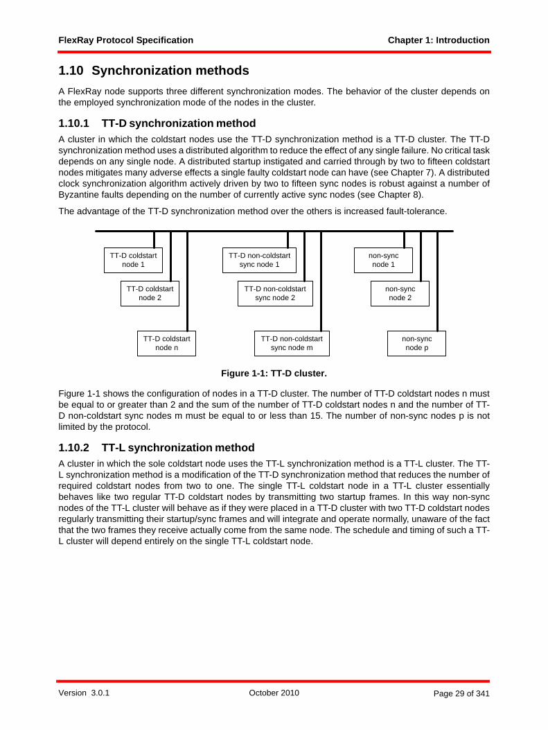
FlexRay Protocol Specification Chapter 1: Introduction
1.10 Synchronization methodsA FlexRay node supports three different synchronization modes. The behavior of the cluster depends onthe employed synchronization mode of the nodes in the cluster.
1.10.1 TT-D synchronization methodA cluster in which the coldstart nodes use the TT-D synchronization method is a TT-D cluster. The TT-Dsynchronization method uses a distributed algorithm to reduce the effect of any single failure. No critical taskdepends on any single node. A distributed startup instigated and carried through by two to fifteen coldstartnodes mitigates many adverse effects a single faulty coldstart node can have (see Chapter 7). A distributedclock synchronization algorithm actively driven by two to fifteen sync nodes is robust against a number ofByzantine faults depending on the number of currently active sync nodes (see Chapter 8).
The advantage of the TT-D synchronization method over the others is increased fault-tolerance.
Figure 1-1: TT-D cluster.
Figure 1-1 shows the configuration of nodes in a TT-D cluster. The number of TT-D coldstart nodes n mustbe equal to or greater than 2 and the sum of the number of TT-D coldstart nodes n and the number of TT-D non-coldstart sync nodes m must be equal to or less than 15. The number of non-sync nodes p is notlimited by the protocol.
1.10.2 TT-L synchronization methodA cluster in which the sole coldstart node uses the TT-L synchronization method is a TT-L cluster. The TT-L synchronization method is a modification of the TT-D synchronization method that reduces the number ofrequired coldstart nodes from two to one. The single TT-L coldstart node in a TT-L cluster essentiallybehaves like two regular TT-D coldstart nodes by transmitting two startup frames. In this way non-syncnodes of the TT-L cluster will behave as if they were placed in a TT-D cluster with two TT-D coldstart nodesregularly transmitting their startup/sync frames and will integrate and operate normally, unaware of the factthat the two frames they receive actually come from the same node. The schedule and timing of such a TT-L cluster will depend entirely on the single TT-L coldstart node.
TT-D coldstart node 1
TT-D coldstart node 2
TT-D coldstart node n
TT-D non-coldstart sync node 1
TT-D non-coldstart sync node 2
TT-D non-coldstart sync node m
non-syncnode 1
non-syncnode 2
non-syncnode p
Version 3.0.1 October 2010 Page 29 of 341

FlexRay Protocol Specification Chapter 1: Introduction
The advantages of the TT-L synchronization method are a reduced system complexity, a slightly reducedstartup time, and an improved precision.
Figure 1-2: TT-L cluster.
Figure 1-2 shows the configuration of nodes in a TT-L cluster. There exists exactly one TT-L coldstart node.The number of non-sync nodes p is not limited by the protocol.
1.10.3 TT-E synchronization methodA cluster in which the coldstart nodes use the TT-E synchronization method is a TT-E cluster. The primaryintent of the TT-E synchronization method is to synchronize the schedule of the TT-E cluster, also called atime sink cluster, to a second FlexRay cluster, which is referred to as time source cluster. To that end, eachTT-E coldstart node, also called a time gateway sink node, must be paired with a node of its time sourcecluster; this pair of nodes is called a time gateway. The node on the time sink cluster side is then called atime gateway sink node while the node on the time source cluster side is called time gateway source node.Figure 1-3 depicts the basic setup. Depending on the synchronization method employed by time sourcecluster, the time gateway source node may be a TT-D coldstart node, a TT-D non-coldstart sync node, a TT-L coldstart node, or a non-sync node.6 The two nodes of the time gateway are connected via a time gatewayinterface, which is used by the time gateway source node to provide information about the schedule of thetime source cluster to the time gateway sink node.
Instead of the usual distributed startup, a TT-E coldstart node derives the cycle length and position of thecycle start from its time gateway source node and directly starts transmitting according to this schedule(slightly shifted with a fixed offset of cdTSrcCycleOffset microticks). Similar to the TT-L synchronizationmethod, each TT-E coldstart node transmits two startup frames, so that a single TT-E coldstart nodesuffices to start and maintain a TT-E cluster. Contrary to the TT-L synchronization method, multiple TT-Ecoldstart nodes may be present in a TT-E cluster. As all TT-E coldstart nodes derive their schedule from thesame cluster, they are implicitly synchronized to one another.
6 In theory it is also possible for the time gateway source node to be a TT-E coldstart node, but this would imply a time gateway that includes three or more distinct nodes. Such configurations are beyond the scope of this specification.
TT-L coldstart node 1
non-syncnode 1
non-syncnode 2
non-syncnode p
Version 3.0.1 October 2010 Page 30 of 341

FlexRay Protocol Specification Chapter 1: Introduction
Figure 1-3: Time synchronized cluster pair.
The advantage of the TT-E synchronization method is the close coupling of the schedule of a TT-E clusterto another FlexRay cluster. In this way, a single FlexRay cluster may be split into synchronized sub-clustersto avoid limits on attached nodes placed upon a single FlexRay cluster by [EPL10] or to enable a separationof nodes into multiple clusters according to communication needs for a more efficient use of the availablebandwidth.
Figure 1-4 shows the configuration of two connected clusters, the lower being a time sink cluster, the upperbeing a time source cluster, in this case a TT-D cluster. The TT-D cluster could also be replaced by a TT-Lcluster or TT-E cluster.7 The number of TT-E coldstart nodes i must be at least one and less than or equalto 7. The number of non-sync nodes k is not limited by the protocol.
The support of the TT-E synchronization method is optional. This means that a FlexRay node may notsupport being a TT-E coldstart node, may not support being a time gateway source node, or may supportneither of these features.
7 This specification does not provide configuration constraints for a "daisy-chain" of TT-E clusters. All configuration constraints assume that a time source cluster is either a TT-D cluster or a TT-L cluster.
Time SinkCluster
Time SourceCluster
Node
TimeGateway
Time GatewayInterface
CommunicationChannel
Time Gateway Source Node
Time Gateway Source Node
Time Gateway Sink Node
Time Gateway Sink Node
Optional Gateway Components
Time Synchronized Cluster Pair
Version 3.0.1 October 2010 Page 31 of 341
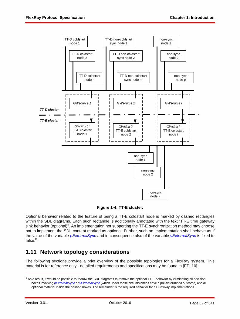
FlexRay Protocol Specification Chapter 1: Introduction
Figure 1-4: TT-E cluster.
Optional behavior related to the feature of being a TT-E coldstart node is marked by dashed rectangleswithin the SDL diagrams. Each such rectangle is additionally annotated with the text "TT-E time gatewaysink behavior (optional)". An implementation not supporting the TT-E synchronization method may choosenot to implement the SDL content marked as optional. Further, such an implementation shall behave as ifthe value of the variable pExternalSync and in consequence also of the variable vExternalSync is fixed tofalse.8
1.11 Network topology considerationsThe following sections provide a brief overview of the possible topologies for a FlexRay system. Thismaterial is for reference only - detailed requirements and specifications may be found in [EPL10].
8 As a result, it would be possible to redraw the SDL diagrams to remove the optional TT-E behavior by eliminating all decision boxes involving pExternalSync or vExternalSync (which under these circumstances have a pre-determined outcome) and all optional material inside the dashed boxes. The remainder is the required behavior for all FlexRay implementations.
GWsink 1:TT-E coldstart
node 1
GWsink 2:TT-E coldstart
node 2
GWsink i:TT-E coldstart
node i
non-syncnode 1
non-syncnode 2
non-syncnode k
GWsource 1 GWsource 2 GWsource i
TT-D coldstart node n
TT-D non-coldstart sync node m
non-syncnode p
TT-D coldstart node 2
TT-D non-coldstart sync node 2
non-syncnode 2
TT-D coldstart node 1
TT-D non-coldstart sync node 1
non-syncnode 1
TT-D cluster
TT-E cluster
Version 3.0.1 October 2010 Page 32 of 341

FlexRay Protocol Specification Chapter 1: Introduction
There are several ways to design a FlexRay cluster. It can be configured as a single-channel or dual-channel bus network, a single-channel or dual-channel star network, or in various hybrid combinations ofbus and star topologies.
A FlexRay cluster consists of at most two channels, identified as Channel A and Channel B. Each node inthe cluster may be connected to either or both of the channels. In the fault free condition, all nodesconnected to Channel A are able to communicate with all other nodes connected to Channel A, and allnodes connected to Channel B are able to communicate with all other nodes connected to Channel B. If anode needs to be connected to more than one cluster then the connection to each cluster must be madethrough a different communication controller9.
1.11.1 Passive bus topologyFigure 1-5 shows the possible topology configuration of the communication network as a dual bus. A nodecan be connected to both channels A and B (nodes A, C, and E), only to channel A (node D), or only tochannel B (node B).
Figure 1-5: Dual channel bus configuration.
The FlexRay communication network can also be a single bus. In this case, all nodes are connected to thisbus.
1.11.2 Active star topologyA FlexRay communication network can be built as a multiple star topology. Similar to the bus topology, themultiple-star topology can support redundant communication channels. Each network channel must be freeof closed rings, and there can be no more than two active stars on a network channel10. Note that there maybe physical layer-related restrictions that limit the number of active stars for certain bit rates - see [EPLAN10]for details.
An incoming signal received on a branch of an active star is actively driven to all other branches of the activestar.
9 For example, it is not allowed for a communication controller to connect to Channel A of one cluster and Channel B of another cluster.
10 A channel with two active stars would have the stars connected to each other. Communication between nodes connected to different stars would pass through both stars (a cascaded star topology).
Channel A
Channel B
Node A Node B Node C Node D Node E
Version 3.0.1 October 2010 Page 33 of 341
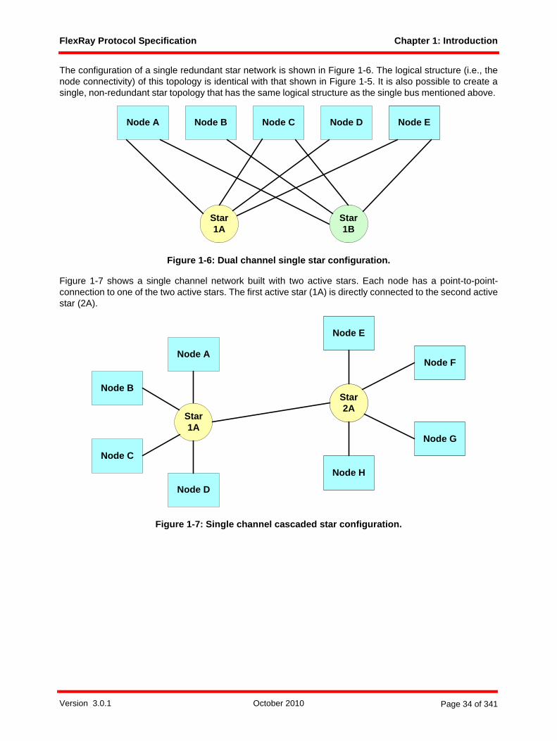
FlexRay Protocol Specification Chapter 1: Introduction
The configuration of a single redundant star network is shown in Figure 1-6. The logical structure (i.e., thenode connectivity) of this topology is identical with that shown in Figure 1-5. It is also possible to create asingle, non-redundant star topology that has the same logical structure as the single bus mentioned above.
Figure 1-6: Dual channel single star configuration.
Figure 1-7 shows a single channel network built with two active stars. Each node has a point-to-point-connection to one of the two active stars. The first active star (1A) is directly connected to the second activestar (2A).
Figure 1-7: Single channel cascaded star configuration.
Node A Node B Node C Node D Node E
Star1A
Star1B
Star1A
Star2A
Node C
Node E
Node F
Node H
Node G
Node A
Node B
Node D
Version 3.0.1 October 2010 Page 34 of 341

FlexRay Protocol Specification Chapter 1: Introduction
Note that it is also possible to have a redundant channel configuration with cascaded stars. An example ofsuch a configuration is Figure 1-8. Note that this example does not simply replicate the set of stars for thesecond channel - Star 1A connects nodes A, B, and C, while Star 1B connects nodes A, C, and E.
Figure 1-8: Dual channel cascaded star configuration.
1.11.3 Active star topology combined with a passive bus topologyIn addition to topologies that are composed either entirely of a bus topology or entirely of a star topology, itis possible to have hybrid topologies that are a mixture of bus and star configurations. The FlexRay systemsupports such hybrid topologies as long as the limits applicable to each individual topology are notexceeded. For example, the limit of two cascaded active stars also limits the number of cascaded activestars in a hybrid topology.
There are a large number of possible hybrid topologies, but only two representative topologies are shownhere. Figure 1-9 shows an example of one type of hybrid topology. In this example, some nodes (nodes A,B, C, and D) are connected using point-to-point connections to an active star. Other nodes (nodes E, F, andG) are connected to each other using a bus topology. This bus is also connected to an active star, allowingnodes E, F, and G to communicate with the other nodes.
Node A Node B Node C Node D Node E Node F
Star1A
Star1B
Star2A
Star2B
Version 3.0.1 October 2010 Page 35 of 341

FlexRay Protocol Specification Chapter 1: Introduction
Figure 1-9: Single channel hybrid example.
A fundamentally different type of hybrid topology is shown in Figure 1-10. In this case, different topologiesare used on different channels. Here, channel A is implemented as a bus topology connection, whilechannel B is implemented as a star topology connection.
Figure 1-10: Dual channel hybrid example.
The protocol implications of topologies with stubs on the connection between active stars have not beenfully analyzed. As a result, such topologies are not recommended and are not considered in this specifi-cation.
Star1A
Star2A
Node B Node C
Node DNode A
Node GNode FNode E
Node A Node B Node C Node D Node E
Star1B
Channel A
Version 3.0.1 October 2010 Page 36 of 341

FlexRay Protocol Specification Chapter 1: Introduction
1.12 Example node architecture1.12.1 ObjectiveThis section is intended to provide insight into the FlexRay architecture by discussing an example nodearchitecture and the interfaces between the FlexRay hardware devices.
The information in this section is for reference only. The detailed specification of the interfaces is given inthe electrical physical layer specification [EPL10]; references are made here to appropriate text passagesfrom this document.
Note that an active star component can also function in a role similar to a bus driver via the use of theoptional BD-CC interface as described in [EPL10]. The following sections describe the node architectureunder the assumption that the CC interfaces to the channel(s) via a bus driver rather than via an active star.
1.12.2 OverviewFigure 1-11 depicts an example node architecture. One communication controller, one host, one powersupply unit, and two bus drivers are depicted. Each communication channel has one bus driver to connectthe node to the channel. In addition to the indicated communication and control data interfaces an optionalinterface between the bus driver and the power supply unit may exist.
Figure 1-11: Logical interfaces.
1.12.3 Host - communication controller interface The host and the communication controller share a substantial amount of information. The host providescontrol and configuration information to the CC, and provides payload data that is transmitted during thecommunication cycle. The CC provides status information to the host and delivers payload data receivedfrom communication frames.
Host
Bus Driver
Communication Controller
Power Supply
Com
mun
icat
ion
Dat
a
Control Data &Status Information
Control Signals (optional)
Communication Data
Con
trol S
igna
l
Com
mun
icat
ion
Dat
a
Con
trol S
igna
l
Configuration Data &Status Information
Version 3.0.1 October 2010 Page 37 of 341
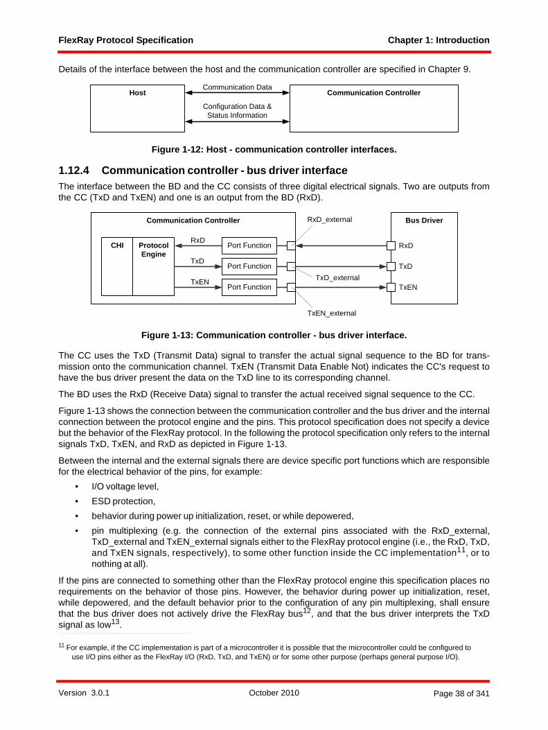
FlexRay Protocol Specification Chapter 1: Introduction
Details of the interface between the host and the communication controller are specified in Chapter 9.
Figure 1-12: Host - communication controller interfaces.
1.12.4 Communication controller - bus driver interfaceThe interface between the BD and the CC consists of three digital electrical signals. Two are outputs fromthe CC (TxD and TxEN) and one is an output from the BD (RxD).
Figure 1-13: Communication controller - bus driver interface.
The CC uses the TxD (Transmit Data) signal to transfer the actual signal sequence to the BD for trans-mission onto the communication channel. TxEN (Transmit Data Enable Not) indicates the CC's request tohave the bus driver present the data on the TxD line to its corresponding channel.
The BD uses the RxD (Receive Data) signal to transfer the actual received signal sequence to the CC.
Figure 1-13 shows the connection between the communication controller and the bus driver and the internalconnection between the protocol engine and the pins. This protocol specification does not specify a devicebut the behavior of the FlexRay protocol. In the following the protocol specification only refers to the internalsignals TxD, TxEN, and RxD as depicted in Figure 1-13.
Between the internal and the external signals there are device specific port functions which are responsiblefor the electrical behavior of the pins, for example:
• I/O voltage level,• ESD protection,• behavior during power up initialization, reset, or while depowered,• pin multiplexing (e.g. the connection of the external pins associated with the RxD_external,
TxD_external and TxEN_external signals either to the FlexRay protocol engine (i.e., the RxD, TxD,and TxEN signals, respectively), to some other function inside the CC implementation11, or tonothing at all).
If the pins are connected to something other than the FlexRay protocol engine this specification places norequirements on the behavior of those pins. However, the behavior during power up initialization, reset,while depowered, and the default behavior prior to the configuration of any pin multiplexing, shall ensurethat the bus driver does not actively drive the FlexRay bus12, and that the bus driver interprets the TxDsignal as low13.
11 For example, if the CC implementation is part of a microcontroller it is possible that the microcontroller could be configured to use I/O pins either as the FlexRay I/O (RxD, TxD, and TxEN) or for some other purpose (perhaps general purpose I/O).
Host Communication Controller
Configuration Data &Status Information
Communication Data
Bus DriverRxD_externalCommunication Controller
TxD_external
TxEN_external
Protocol Engine
RxD
TxD
TxEN
Port Function
Port Function
Port Function
CHI RxD
TxD
TxEN
Version 3.0.1 October 2010 Page 38 of 341

FlexRay Protocol Specification Chapter 1: Introduction
Some requirements (e.g. the electrical characteristics and timing) on the port functions and theTxD_external, TxEN_external and RxD_external signals are specified in [EPL10].
1.12.5 Bus driver - host interfaceThe interface between the BD and the host allows the host to control the operating modes of the BD and toread error conditions and status information from the BD.
This interface can be realized using hard-wired signals (see option A in Figure 1-14) or by a Serial PeripheralInterface (SPI) (see option B in Figure 1-15).
1.12.5.1 Hard wired signals (option A)This implementation of the BD - host interface uses discrete hard wired signals. The interface consists of atleast an STBN (Standby Not) signal that is used to control the BD's operating mode and an ERRN (ErrorNot) signal that is used by the BD to indicate detected errors. The interface could also include additionalcontrol signals (the "EN" signal is shown as an example) that support control of optional operational modes.
Figure 1-14: Example bus driver - host interface (option A).
This interface is product specific; some restrictions are given in [EPL10] that define minimum functionalityto ensure interoperability.
1.12.5.2 Serial peripheral interface (SPI) (option B)This implementation of the BD - host interface uses an SPI link to allow the host to command the BDoperating mode and to read out the status of the BD. In addition, the BD has a hardwired interrupt output(INTN).
The electrical characteristics and timing of this interface are specified in [EPL10].
12 This could be done, for example, by ensuring that the TxEN_external output is driven to active high, provided with a weak pull up, or set to high impedance.
13 This could be done, for example, by ensuring that the TxD_external output is driven to active low, provided with a weak pull down, or set to high impedance.
STBN
EN
ERRN
Host Bus Driver
Version 3.0.1 October 2010 Page 39 of 341

FlexRay Protocol Specification Chapter 1: Introduction
Figure 1-15: Example bus driver - host interface (option B).
1.12.6 Bus driver - power supply interface (optional)The inhibit signal (INH1) is an optional interface that allows the BD to directly control the power supply of anECU. This signal could also be used as one of a set of signals that control the power moding of the ECU.
Figure 1-16: Bus driver - power supply interface.
The electrical characteristics and behavior of the INH1 signal are specified in [EPL10].
1.12.7 Time gateway interfaceA time gateway sink node needs information on the schedule and clock synchronization algorithm of its timegateway source node. The time gateway source node provides this information via the time gatewayinterface to the time gateway sink node. This interface is unidirectional - no information flows back from thetime gateway sink node to the time gateway source node. This interface is an optional feature only requiredto allow the node to be a time gateway source or time gateway sink node. Details of the interface betweenthe time gateway source node and the time gateway sink node are specified in Chapter 8. The usage of thisinterface is indicated in the SDL diagrams by the EXP keyword on the transmitting end and the IMP keywordon the receiving end.
Figure 1-17: Time gateway interface.
1.13 Testability requirementsThe FlexRay Protocol Conformance Test Specification [PCT10] contains additional implementation require-ments. The purpose of these requirements is to facilitate testing, for example by establishing timing boundsfor the availability of CHI information necessary to execute certain tests.
INTN
SCK
SDO
SDI
Bus DriverHost
SCSN
INH1
Power SupplyBus Driver
Time Gateway Source Node
Time Gateway Sink NodeTime & Status Information
Version 3.0.1 October 2010 Page 40 of 341
FlexRay Protocol Specification Chapter 2: Protocol Operation Control
Chapter 2Protocol Operation Control
This chapter defines how the core mechanisms of the protocol are moded in response to host commandsand protocol conditions.
2.1 PrinciplesThe primary protocol behavior of FlexRay is embodied in four core mechanisms, each of which is describedin a dedicated chapter of this specification.
• Coding and Decoding (see Chapter 3)• Media Access Control (see Chapter 5)• Frame and Symbol Processing (see Chapter 6)• Clock Synchronization (see Chapter 8)
In addition, the controller host interface (CHI) provides the mechanism for the host to interact in a structuredmanner with these core mechanisms and for the protocol mechanisms, including Protocol Operation Control(POC), to provide feedback to the host (see Chapter 9).
Each of the core mechanisms possesses modal behavior that allows it to alter its fundamental operation inresponse to high-level mode changes of the node. Proper protocol behavior can only occur if the modechanges of the core mechanisms are properly coordinated and synchronized. The purpose of the POC isto react to host commands and protocol conditions by triggering coherent changes to core mechanisms ina synchronous manner, and to provide the host with the appropriate status regarding these changes.
The necessary synchronization of the core mechanisms is particularly evident during the wakeup, startupand reintegration procedures. These procedures are described in detail in Chapter 7. However, theseprocedures are wholly included in the POC as macros in the POC SDL models. They can be viewed asspecialized extensions of the POC.
2.1.1 Communication controller power modingBefore the POC can perform its prescribed tasks the communication controller (CC) must achieve a statewhere there is a stable power supply. Furthermore, the POC can only continue to operate while a stablepower supply is present.
Version 3.0.1 October 2010 Page 41 of 341

FlexRay Protocol Specification Chapter 2: Protocol Operation Control
Figure 2-1: Power moding of the communication controller.
Figure 2-1 depicts an overview of the CC power moding operation. Note that in this figure the state labeledPOC operational is not actually a specific state but rather a superset of all operational states of the ProtocolOperation Control (see Figure 2-3).
In the power off state there is insufficient power for the CC to operate14. In the power on state (includingboth reset and POC operational) the CC shall guarantee that all pins are in prescribed states. In the POCoperational state the CC shall drive the pins in accordance with the product specification. The POC controlsthe other protocol mechanisms in the manner described in this chapter while the CC is in the POC opera-tional state.
2.2 DescriptionThe relationships between the CHI, POC and the core mechanisms are depicted in Figure 2-215.
14 While the CC cannot enforce specific behavior of the pins, there shall be product-specific behavior specified (e.g. high impedance).
15 The dark lines represent data flows between mechanisms that are relevant to this chapter. The lighter gray lines are relevant to the protocol, but not to this chapter.
power off
POC operational
reset
power on
Version 3.0.1 October 2010 Page 42 of 341

FlexRay Protocol Specification Chapter 2: Protocol Operation Control
Figure 2-2: Protocol operation control context.
2.2.1 Operational overviewThe POC SDL process is created as the CC enters the POC operational state and terminated when the CCexits it. The POC process is responsible for creating the SDL processes corresponding to the coremechanisms and informing those processes when they are required to terminate. It is also responsible forchanging the mode of the core mechanisms of the protocol in response to changing conditions in the node.
Mode changes of the core mechanisms occur when the POC itself changes states. Some of the POC statechanges are simply a consequence of completing tasks. For example, the POC:normal active state (seesection 2.3.6) is entered as a consequence of completing the startup process. However, most of the POCstate changes are a direct consequence of one of the following:
• Host commands communicated to the POC via the CHI.• Error conditions detected either by the protocol engine or a product-specific built-in self-test (BIST)
or sanity check. The host may also perform sanity checks, but the consequences of the host sanitychecks are indicated to the POC as host commands.
frame and symbolprocessing
media accesscontrol
clock synchronization
startup
macrotickgeneration
clock synchronization
processing
protocoloperation
control
controllerhost interface
coding / decoding processeschannel A
frame and symbolprocessingchannel A
media accesscontrol
channel A
clock synchronization
startup channel A
to channel interface from channel interface
to / from host
media accesscontrolchannel B
coding / decodingprocesseschannel B
frame and symbolprocessingchannel B
clock synchronization
startup channel B
Version 3.0.1 October 2010 Page 43 of 341
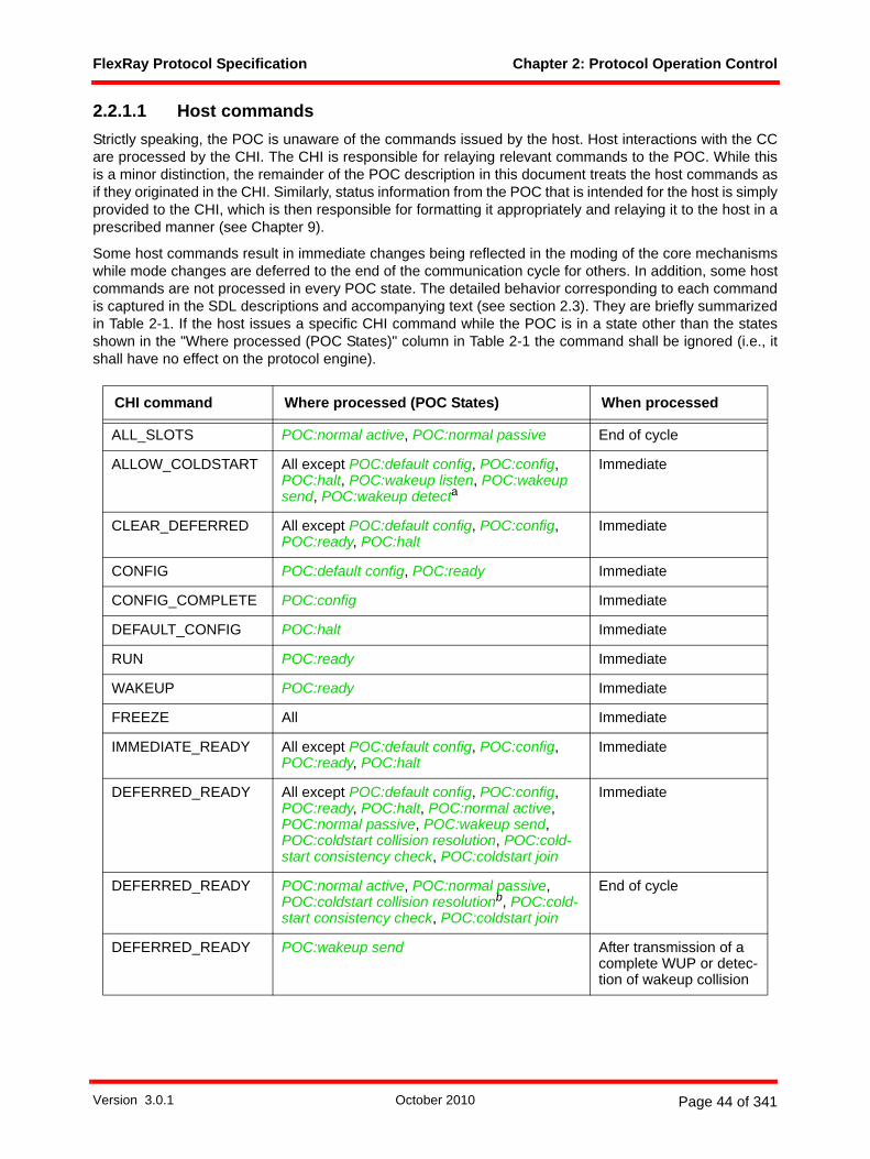
FlexRay Protocol Specification Chapter 2: Protocol Operation Control
2.2.1.1 Host commandsStrictly speaking, the POC is unaware of the commands issued by the host. Host interactions with the CCare processed by the CHI. The CHI is responsible for relaying relevant commands to the POC. While thisis a minor distinction, the remainder of the POC description in this document treats the host commands asif they originated in the CHI. Similarly, status information from the POC that is intended for the host is simplyprovided to the CHI, which is then responsible for formatting it appropriately and relaying it to the host in aprescribed manner (see Chapter 9).
Some host commands result in immediate changes being reflected in the moding of the core mechanismswhile mode changes are deferred to the end of the communication cycle for others. In addition, some hostcommands are not processed in every POC state. The detailed behavior corresponding to each commandis captured in the SDL descriptions and accompanying text (see section 2.3). They are briefly summarizedin Table 2-1. If the host issues a specific CHI command while the POC is in a state other than the statesshown in the "Where processed (POC States)" column in Table 2-1 the command shall be ignored (i.e., itshall have no effect on the protocol engine).
CHI command Where processed (POC States) When processed
ALL_SLOTS POC:normal active, POC:normal passive End of cycle
ALLOW_COLDSTART All except POC:default config, POC:config, POC:halt, POC:wakeup listen, POC:wakeup send, POC:wakeup detecta
Immediate
CLEAR_DEFERRED All except POC:default config, POC:config, POC:ready, POC:halt
Immediate
CONFIG POC:default config, POC:ready Immediate
CONFIG_COMPLETE POC:config Immediate
DEFAULT_CONFIG POC:halt Immediate
RUN POC:ready Immediate
WAKEUP POC:ready Immediate
FREEZE All Immediate
IMMEDIATE_READY All except POC:default config, POC:config, POC:ready, POC:halt
Immediate
DEFERRED_READY All except POC:default config, POC:config, POC:ready, POC:halt, POC:normal active, POC:normal passive, POC:wakeup send, POC:coldstart collision resolution, POC:cold-start consistency check, POC:coldstart join
Immediate
DEFERRED_READY POC:normal active, POC:normal passive, POC:coldstart collision resolutionb, POC:cold-start consistency check, POC:coldstart join
End of cycle
DEFERRED_READY POC:wakeup send After transmission of a complete WUP or detec-tion of wakeup collision
Version 3.0.1 October 2010 Page 44 of 341

FlexRay Protocol Specification Chapter 2: Protocol Operation Control
Table 2-1: CHI host command summary.
2.2.1.2 Error conditionsThe POC contains two basic mechanisms for responding to errors. For significant errors, the POC:halt stateis immediately entered. The POC also contains a three-state degradation model for errors that can beendured for a limited period of time. In this case entry to the POC:halt state is deferred, at least temporarily,to support possible recovery from a potentially transient condition.
2.2.1.2.1 Errors causing immediate entry to the POC:halt stateThere are three general conditions that trigger entry to the POC:halt state:
• Product-specific error conditions such as BIST errors and sanity checks. • Error conditions detected by the host that result in a FREEZE command being sent to the POC via
the CHI.• Fatal error conditions detected by the FSP process.
Product-specific errors are accommodated by the POC, but not described in this specification (see section2.3.3). Similarly, host detected error strategies are supported by the POC's ability to respond to a hostFREEZE command (see section 2.3.3), but the host-based mechanisms that trigger the command arebeyond the scope of this specification. Only errors detected by the POC or one of the core mechanisms areexplicitly detailed in this specification.
2.2.1.2.2 Errors handled by the degradation modelIntegral to the POC is a three-state error handling mechanism referred to as the degradation model. It isdesigned to react to certain conditions detected by the clock synchronization mechanism that are indicativeof a problem, but that may not require immediate action due to the inherent fault tolerance of the clocksynchronization mechanism. This makes it possible to avoid immediate transitions to the POC:halt statewhile assessing the nature and extent of the errors.
The degradation model is embodied in three POC states - POC:normal active, POC:normal passive, andPOC:halt.
In the POC:normal active state the node is assumed to be either error free, or at least within error boundsthat allow continued "normal operation". Specifically, it is assumed that the node remains adequately time-synchronized to the cluster to allow continued frame transmission without disrupting the transmissions ofother nodes.
DEFERRED_HALT All except POC:halt, POC:normal active, POC:normal passive, POC:wakeup send, POC:coldstart collision resolution, POC:cold-start consistency check, POC:coldstart join
Immediate
DEFERRED_HALT POC:normal active, POC:normal passive, POC:coldstart collision resolutionb, POC:cold-start consistency check, POC:coldstart join
End of cycle
DEFERRED_HALT POC:wakeup send After transmission of a complete WUP or detec-tion of wakeup collision
a. The ALLOW_COLDSTART command is processed as described in Figure 2-13 except when the POC is in the POC:integration listen state, in which case it is processed by the SDL in Figure 7-22.b. In the POC:coldstart collision resolution state a deferred command is either processed at the end of the cycle or after a frame header or a CAS is received.
CHI command Where processed (POC States) When processed
Version 3.0.1 October 2010 Page 45 of 341
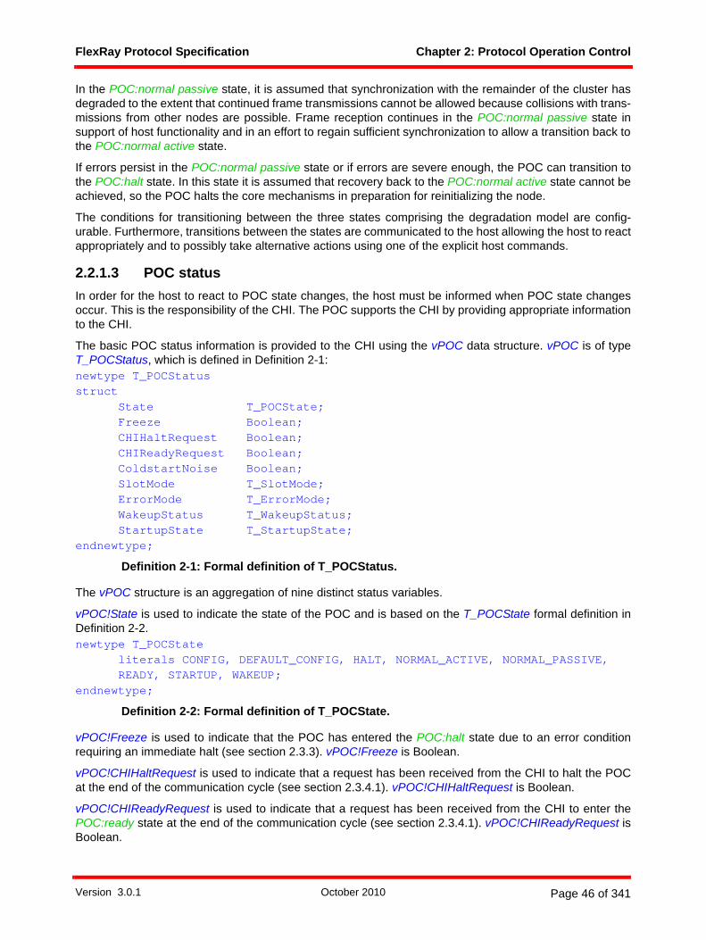
FlexRay Protocol Specification Chapter 2: Protocol Operation Control
In the POC:normal passive state, it is assumed that synchronization with the remainder of the cluster hasdegraded to the extent that continued frame transmissions cannot be allowed because collisions with trans-missions from other nodes are possible. Frame reception continues in the POC:normal passive state insupport of host functionality and in an effort to regain sufficient synchronization to allow a transition back tothe POC:normal active state.
If errors persist in the POC:normal passive state or if errors are severe enough, the POC can transition tothe POC:halt state. In this state it is assumed that recovery back to the POC:normal active state cannot beachieved, so the POC halts the core mechanisms in preparation for reinitializing the node.
The conditions for transitioning between the three states comprising the degradation model are config-urable. Furthermore, transitions between the states are communicated to the host allowing the host to reactappropriately and to possibly take alternative actions using one of the explicit host commands.
2.2.1.3 POC statusIn order for the host to react to POC state changes, the host must be informed when POC state changesoccur. This is the responsibility of the CHI. The POC supports the CHI by providing appropriate informationto the CHI.
The basic POC status information is provided to the CHI using the vPOC data structure. vPOC is of typeT_POCStatus, which is defined in Definition 2-1:newtype T_POCStatusstruct
State T_POCState;Freeze Boolean;CHIHaltRequest Boolean;CHIReadyRequest Boolean;ColdstartNoise Boolean;SlotMode T_SlotMode;ErrorMode T_ErrorMode;WakeupStatus T_WakeupStatus;StartupState T_StartupState;
endnewtype;
Definition 2-1: Formal definition of T_POCStatus.
The vPOC structure is an aggregation of nine distinct status variables.
vPOC!State is used to indicate the state of the POC and is based on the T_POCState formal definition inDefinition 2-2.newtype T_POCState
literals CONFIG, DEFAULT_CONFIG, HALT, NORMAL_ACTIVE, NORMAL_PASSIVE,READY, STARTUP, WAKEUP;
endnewtype;
Definition 2-2: Formal definition of T_POCState.
vPOC!Freeze is used to indicate that the POC has entered the POC:halt state due to an error conditionrequiring an immediate halt (see section 2.3.3). vPOC!Freeze is Boolean.
vPOC!CHIHaltRequest is used to indicate that a request has been received from the CHI to halt the POCat the end of the communication cycle (see section 2.3.4.1). vPOC!CHIHaltRequest is Boolean.
vPOC!CHIReadyRequest is used to indicate that a request has been received from the CHI to enter thePOC:ready state at the end of the communication cycle (see section 2.3.4.1). vPOC!CHIReadyRequest isBoolean.
Version 3.0.1 October 2010 Page 46 of 341
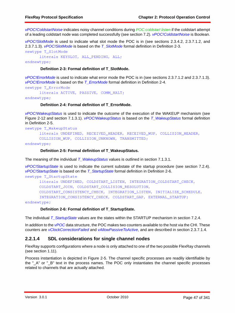
FlexRay Protocol Specification Chapter 2: Protocol Operation Control
vPOC!ColdstartNoise indicates noisy channel conditions during POC:coldstart listen if the coldstart attemptof a leading coldstart node was completed successfully (see section 7.2). vPOC!ColdstartNoise is Boolean.
vPOC!SlotMode is used to indicate what slot mode the POC is in (see sections 2.3.4.2, 2.3.7.1.2, and2.3.7.1.3). vPOC!SlotMode is based on the T_SlotMode formal definition in Definition 2-3.newtype T_SlotMode
literals KEYSLOT, ALL_PENDING, ALL;endnewtype;
Definition 2-3: Formal definition of T_SlotMode.
vPOC!ErrorMode is used to indicate what error mode the POC is in (see sections 2.3.7.1.2 and 2.3.7.1.3).vPOC!ErrorMode is based on the T_ErrorMode formal definition in Definition 2-4.newtype T_ErrorMode
literals ACTIVE, PASSIVE, COMM_HALT;endnewtype;
Definition 2-4: Formal definition of T_ErrorMode.
vPOC!WakeupStatus is used to indicate the outcome of the execution of the WAKEUP mechanism (seeFigure 2-12 and section 7.1.3.1). vPOC!WakeupStatus is based on the T_WakeupStatus formal definitionin Definition 2-5.newtype T_WakeupStatus
literals UNDEFINED, RECEIVED_HEADER, RECEIVED_WUP, COLLISION_HEADER,COLLISION_WUP, COLLISION_UNKNOWN, TRANSMITTED;
endnewtype;
Definition 2-5: Formal definition of T_WakeupStatus.
The meaning of the individual T_WakeupStatus values is outlined in section 7.1.3.1.
vPOC!StartupState is used to indicate the current substate of the startup procedure (see section 7.2.4).vPOC!StartupState is based on the T_StartupState formal definition in Definition 2-6.newtype T_StartupState
literals UNDEFINED, COLDSTART_LISTEN, INTEGRATION_COLDSTART_CHECK,COLDSTART_JOIN, COLDSTART_COLLISION_RESOLUTION,COLDSTART_CONSISTENCY_CHECK, INTEGRATION_LISTEN, INITIALIZE_SCHEDULE,INTEGRATION_CONSISTENCY_CHECK, COLDSTART_GAP, EXTERNAL_STARTUP;
endnewtype;
Definition 2-6: Formal definition of T_StartupState.
The individual T_StartupState values are the states within the STARTUP mechanism in section 7.2.4.
In addition to the vPOC data structure, the POC makes two counters available to the host via the CHI. Thesecounters are vClockCorrectionFailed and vAllowPassiveToActive, and are described in section 2.3.7.1.4.
2.2.1.4 SDL considerations for single channel nodesFlexRay supports configurations where a node is only attached to one of the two possible FlexRay channels(see section 1.11).
Process instantiation is depicted in Figure 2-5. The channel specific processes are readily identifiable bythe "_A" or "_B" text in the process names. The POC only instantiates the channel specific processesrelated to channels that are actually attached.
Version 3.0.1 October 2010 Page 47 of 341

FlexRay Protocol Specification Chapter 2: Protocol Operation Control
Process termination signal generation is also depicted in Figure 2-5. The channel specific signals are identi-fiable by the "_A" or "_B" text in the signal names. Termination signals sent to a channel specific processthat is not instantiated will have no effect.
Process moding signals are generated throughout the POC. Figure 2-4 is an example that includes all ofthese moding signals. The channel specific moding signals are identifiable by the "on A" or "on B" text inthe signal names. Moding signals, or any other signals, sent to a channel specific process that is not instan-tiated will have no effect.
2.3 The protocol operation control processThis section contains the formalized specification of the POC process. Figure 2-3 depicts an overview of thePOC states and how they interrelate16.
Figure 2-3: Overview of protocol operation control.
2.3.1 POC SDL utilitiesThe nature of the POC is that it performs tasks that often influence all of the core mechanisms simulta-neously. From the perspective of SDL depiction these tasks are visually cumbersome. Macros are used inthe POC for the sole purpose of simplifying the SDL presentation.
In the SDL that follows, there are several instances where the POC transitions to the POC:ready orPOC:halt states. Prior to doing so, the core mechanisms have to be moded appropriately. The two macrosin Figure 2-4 perform these tasks. PROTOCOL_ENGINE_READY modes the core mechanisms appropri-
16 The states depicted as wakeup and startup are actually procedures containing several states. The depiction is simplified for the purpose of an overview.
config
ready
halt
defaultconfig
wakeup startup normalpassive
normalactive
POC operational
Version 3.0.1 October 2010 Page 48 of 341

FlexRay Protocol Specification Chapter 2: Protocol Operation Control
ately for entry to POC:ready, and PROTOCOL_ENGINE_HALT modes the core mechanisms appropriatelyfor entry to POC:halt.
Figure 2-4: Macros to mode the core mechanisms for transitions to the POC:ready and POC:halt states [POC].
The SDL processes associated with the core mechanisms are created simultaneously by the POC. Whilethe processes must terminate themselves, the POC is also responsible for simultaneously triggering this inall of the processes. Figure 2-5 depicts the macros for performing these two tasks.
PROTOCOL_ENGINE_HALT
CODEC control on A (STANDBY),CODEC control on B (STANDBY),FSP control on A (STANDBY),FSP control on B (STANDBY),MAC control on A (STANDBY),MAC control on B (STANDBY),CSP control (STANDBY),EXP sync state (UNSYNC)
PROTOCOL_ENGINE_READY
CODEC control on A (READY),CODEC control on B (READY),FSP control on A (STANDBY),FSP control on B (STANDBY),MAC control on A (STANDBY),MAC control on B (STANDBY),CSP control (STANDBY),EXP sync state (UNSYNC)
’update vPOC in CHI’;’update vClockCorrectionFailed in CHI’;reset(tWakeup);reset(tWakeupNoise);reset(tStartup);reset(tStartupNoise);
vPOC!State := READY;vPOC!StartupState := UNDEFINED;vColdstartInhibit := true;’update vPOC in CHI’;reset(tWakeup);reset(tWakeupNoise);reset(tStartup);reset(tStartupNoise);
pKeySlotOnlyEnabled ?
true
false
vPOC!SlotMode := KEYSLOT;vPOC!SlotMode := ALL;
Version 3.0.1 October 2010 Page 49 of 341

FlexRay Protocol Specification Chapter 2: Protocol Operation Control
Figure 2-5: Macros for creating and terminating processes [POC].
2.3.2 SDL organizationFrom the perspective of procedural flow, the behavior of the POC can be loosely decomposed into fourcomponents to facilitate discussion:
1. Behaviors corresponding to host commands that preempt the regular behavioral flow. 2. Behavior that brings the POC to the POC:ready state.3. Behavior leading from the POC:ready state to the POC:normal active state.4. Behavior once the POC:normal active state has been reached, i.e., during "normal operation".
The remainder of this section addresses these four components in succession, explaining the requiredbehavior using SDL diagrams.
2.3.3 Preempting commandsThere are two commands (FREEZE and IMMEDIATE_READY) that are used to preempt the normalbehavioral flow of the POC. They are depicted in Figure 2-6. It should be emphasized that these commandsalso apply to the behavior contained in the Wakeup and Startup macros (see Figure 2-12) that is detailed inChapter 7.
TERMINATE_ALL_PROCESSES terminate CODEC_A,
terminate CODEC_B,terminate FSP_A,terminate FSP_B,terminate MAC_A,terminate MAC_B,terminate CSP,terminate MTG
INSTANTIATE_ALL_PROCESSES
CODEC_A, FSP_A, MAC_A
’update vPOC in CHI’;pChannels ?
pChannels ?
else
= B
CODEC_B, FSP_B, MAC_B
CSP, MTG
else
= A
Version 3.0.1 October 2010 Page 50 of 341

FlexRay Protocol Specification Chapter 2: Protocol Operation Control
Figure 2-6: POC preempting immediate commands [POC].
When a serious error occurs, the POC is notified to halt the operation of the protocol engine. For thispurpose, a freeze mechanism is supported. There are three methods for triggering the freeze mechanism:
1. A host FREEZE command relayed to the POC by the CHI.2. A fatal protocol error signaled by the FSP process.3. A product-specific error detected by a built-in self-test (BIST) or sanity check.
In all three circumstances the POC shall set vPOC!Freeze to true as an indicator that the event hasoccurred, stop the protocol engine by setting all core mechanism to the STANDBY mode, and then transitionto the POC:halt state17.
At the host's discretion, the ongoing operation of the POC can be interrupted by immediately placing thePOC in the POC:ready state. In response to this command, the POC modes the core mechanisms appro-priately (see section 2.3.1), and then transitions to POC:ready.
2.3.4 Deferred commands
2.3.4.1 DEFERRED_HALT, DEFERRED_READY and CLEAR_DEFERRED commands
The POC supports two deferred control commands that will postpone action until the end of a cycle or atime where the command can be processed with minimal disruption to ongoing processes.
17 Note that the values of vPOC!State and vPOC!StartupState are intentionally not altered so that the CHI can indicate to the host what state the POC was in at the time the freeze occurred.
CHI IMMEDIATE_READY command
ready
halt
vPOC!Freeze := true;
PROTOCOL_ENGINE_HALT
PROTOCOL_ENGINE_READY
CHI FREEZE command,fatal protocol error, product-specific BIST or sanity check
vPOC!CHIHaltRequest := false;vPOC!CHIReadyRequest := false;
*
external sync lost
TT-E time gateway sink behavior (optional)
* (default config, config, ready, halt)
halt
PROTOCOL_ENGINE_HALT
vPOC!State := HALT;
Version 3.0.1 October 2010 Page 51 of 341

FlexRay Protocol Specification Chapter 2: Protocol Operation Control
The CHI may relay the DEFERRED_HALT command from the host at any time the POC is in a state otherthan POC:halt. The CHI may relay the DEFERRED_READY command from the host at any time that itwould be allowed to relay the IMMEDIATE_READY command (see Table 2-1 for details). If no communi-cation is ongoing the effects of these commands is immediate. If communication is ongoing the effects ofthe commands are deferred, in most cases to the processing at the end of the cycle. If the POC is in thePOC:wakeup send state a deferred command is processed after transmission of a complete WUP ordetection of a wakeup collision. If the POC is in the POC:coldstart collision resolution state a deferredcommand is processed at the end of the cycle or after a frame header or a CAS is received. In all caseswhere the processing of the commands is deferred it is necessary to capture indications that the commandshave occurred so that processing can take place at the appropriate time. Figure 2-7 depicts the procedurethat captures these commands.
If an additional DEFERRED_HALT or DEFERRED_READY command is relayed from the CHI prior to thePOC acting on a previous deferred command, the POC will only act upon the most recently receivedcommand.
Figure 2-7: POC preempting deferred commands [POC].
The DEFERRED_HALT command shall be captured by setting the vPOC!CHIHaltRequest value to true ifthe command is not immediately processed. When processed at the end of the current cycle, the
CHI DEFERRED_HALT command
-
CHI DEFERRED_ READY command
-
normal active, normal passive, wakeup send, coldstart collision resolution, coldstart consistency check, coldstart join
CHI DEFERRED_HALT command
CHI DEFERRED_READY command
* (halt, normal active, normal passive, wakeup send, coldstart collision resolution, coldstart consistency check, coldstart join)
readyhalt
PROTOCOL_ENGINE_HALT
PROTOCOL_ENGINE_READY
vPOC!CHIHaltRequest:=false;vPOC!CHIReadyRequest := false;
* (default config, config, ready, halt,normal active, normal passive, wakeup send, coldstart collision resolution, coldstart consistency check, coldstart join)
vPOC!State := HALT;vPOC!CHIHaltRequest:= false;vPOC!CHIReadyRequest := false;
vPOC!CHIReadyRequest := true;vPOC!CHIHaltRequest := false;’update vPOC in CHI’;
vPOC!CHIHaltRequest := true;vPOC!CHIReadyRequest := false;’update vPOC in CHI’;
Version 3.0.1 October 2010 Page 52 of 341
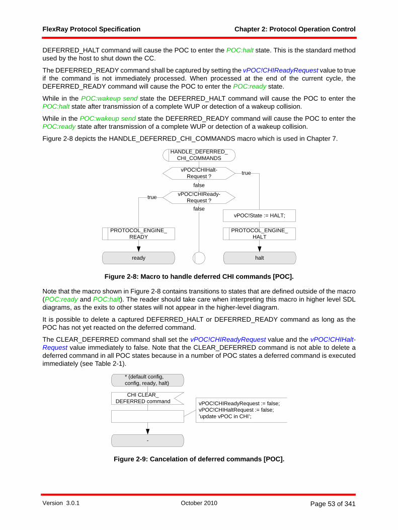
FlexRay Protocol Specification Chapter 2: Protocol Operation Control
DEFERRED_HALT command will cause the POC to enter the POC:halt state. This is the standard methodused by the host to shut down the CC.
The DEFERRED_READY command shall be captured by setting the vPOC!CHIReadyRequest value to trueif the command is not immediately processed. When processed at the end of the current cycle, theDEFERRED_READY command will cause the POC to enter the POC:ready state.
While in the POC:wakeup send state the DEFERRED_HALT command will cause the POC to enter thePOC:halt state after transmission of a complete WUP or detection of a wakeup collision.
While in the POC:wakeup send state the DEFERRED_READY command will cause the POC to enter thePOC:ready state after transmission of a complete WUP or detection of a wakeup collision.
Figure 2-8 depicts the HANDLE_DEFERRED_CHI_COMMANDS macro which is used in Chapter 7.
Figure 2-8: Macro to handle deferred CHI commands [POC].
Note that the macro shown in Figure 2-8 contains transitions to states that are defined outside of the macro(POC:ready and POC:halt). The reader should take care when interpreting this macro in higher level SDLdiagrams, as the exits to other states will not appear in the higher-level diagram.
It is possible to delete a captured DEFERRED_HALT or DEFERRED_READY command as long as thePOC has not yet reacted on the deferred command.
The CLEAR_DEFERRED command shall set the vPOC!CHIReadyRequest value and the vPOC!CHIHalt-Request value immediately to false. Note that the CLEAR_DEFERRED command is not able to delete adeferred command in all POC states because in a number of POC states a deferred command is executedimmediately (see Table 2-1).
Figure 2-9: Cancelation of deferred commands [POC].
HANDLE_DEFERRED_ CHI_COMMANDS
vPOC!CHIHalt-Request ?
vPOC!CHIReady-Request ?
false
false
ready halt
true
vPOC!State := HALT;
PROTOCOL_ENGINE_HALT
PROTOCOL_ENGINE_READY
true
* (default config, config, ready, halt)
CHI CLEAR_DEFERRED command
-
vPOC!CHIReadyRequest := false;vPOC!CHIHaltRequest := false;’update vPOC in CHI’;
Version 3.0.1 October 2010 Page 53 of 341
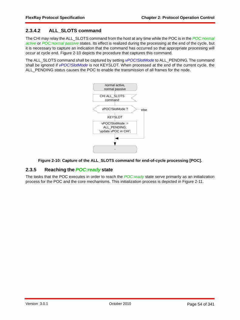
FlexRay Protocol Specification Chapter 2: Protocol Operation Control
2.3.4.2 ALL_SLOTS commandThe CHI may relay the ALL_SLOTS command from the host at any time while the POC is in the POC:normalactive or POC:normal passive states. Its effect is realized during the processing at the end of the cycle, butit is necessary to capture an indication that the command has occurred so that appropriate processing willoccur at cycle end. Figure 2-10 depicts the procedure that captures this command.
The ALL_SLOTS command shall be captured by setting vPOC!SlotMode to ALL_PENDING. The commandshall be ignored if vPOC!SlotMode is not KEYSLOT. When processed at the end of the current cycle, theALL_PENDING status causes the POC to enable the transmission of all frames for the node.
Figure 2-10: Capture of the ALL_SLOTS command for end-of-cycle processing [POC].
2.3.5 Reaching the POC:ready stateThe tasks that the POC executes in order to reach the POC:ready state serve primarily as an initializationprocess for the POC and the core mechanisms. This initialization process is depicted in Figure 2-11.
normal active, normal passive
CHI ALL_SLOTS command
vPOC!SlotMode := ALL_PENDING;
’update vPOC in CHI’;
-
KEYSLOT
vPOC!SlotMode ? else
Version 3.0.1 October 2010 Page 54 of 341

FlexRay Protocol Specification Chapter 2: Protocol Operation Control
Figure 2-11: Reaching the POC:ready state [POC].
The POC shall enter the POC:default config state when the CC enters the POC operational state (seesection 2.1.1). The POC:default config shall also be entered from the POC:halt state if aDEFAULT_CONFIG command is received from the CHI. In the latter case, the POC shall signal the coremechanisms to terminate so that they can be created again as a part of the normal initialization process.
default config
CHI CONFIG command
config
CHI CONFIG_COMPLETE command
ready
dcl vPOC T_POCStatus;dcl vCycleCounter T_CycleCounter;dcl zSyncCalcResult T_SyncCalcResult;dcl zStartupX T_SyncFrameIDCount;dcl zRefX Boolean;dcl vClockCorrectionFailed Integer;dcl vAllowPassiveToActive Integer;dcl zChannelIdle T_ChannelBoolArray;dcl vColdstartInhibit Boolean := true;
vPOC!State := DEFAULT_CONFIG;vPOC!Freeze := false;vPOC!CHIHaltRequest := false;vPOC!CHIReadyRequest := false;vPOC!ColdstartNoise := false;vPOC!SlotMode := KEYSLOT;vPOC!ErrorMode := ACTIVE;vPOC!WakeupStatus := UNDEFINED;vPOC!StartupState := UNDEFINED;vClockCorrectionFailed := 0;vAllowPassiveToActive := 0;’update vPOC in CHI’;’update vClockCorrectionFailed in CHI’;'update vAllowPassiveToActive in CHI';
halt
CHI DEFAULT_CONFIG command
vPOC!State := CONFIG;’update vPOC in CHI’;
TERMINATE_ALL_PROCESSES
PROTOCOL_ENGINE_READY
INSTANTIATE_ALL_PROCESSES
pChannels ?
zChannelIdle(A) := false;zChannelIdle(B) := false;
zChannelIdle(A) := true;zChannelIdle(B) := false;
zChannelIdle(A) := false;zChannelIdle(B) := true;
= B = A
= A&B
Version 3.0.1 October 2010 Page 55 of 341

FlexRay Protocol Specification Chapter 2: Protocol Operation Control
Prior to entering the POC:default config state the POC shall initialize the elements of the vPOC datastructure that are used to communicate the POC status to the CHI. With the exception of vPOC!SlotMode,the values assumed by the vPOC elements are obvious initial values and are depicted in Figure 2-11. Theinitial value of vPOC!SlotMode is defaulted to KEYSLOT until the configuration process is carried out to setit to the value desired by the host.
In the POC:default config state the POC awaits the explicit command from the host to enable configuration.The POC shall enter the POC:config state in response to the CONFIG command. Configuration of the CCis only allowed in the POC:config state and this state can only be entered with an explicit CONFIG commandissued while the POC is in the POC:default config state or the POC:ready state (see section 2.3.6).
In the POC:config state the host configures the CC. The host is responsible for verifying this configurationand only allowing the initialization to proceed when a proper configuration is verified. For this purpose, anexplicit CONFIG_COMPLETE command is required for the POC to progress from the POC:config state.
The POC shall transition to the POC:ready state in response to the CONFIG_COMPLETE command. Onthis transition, the POC shall create all of the core mechanism processes, incorporating the configurationvalues that were set in the POC:config state. It shall then update vPOC to reflect the new state, the newlyconfigured value of slot mode18, and the initial value of vColdstartInhibit. It shall then command all of thecore mechanisms to their appropriate mode (see section 2.3.1). The POC then transitions to the POC:readystate.
2.3.5.1 Default configuration requirementsPOC:default config is a state that ensures that the CC has a defined, stable default configuration prior toapplication-specific configuration that takes place in the POC:config state. Upon entry into the POC:defaultconfig state the CC must ensure that all configuration data or control data described in sections 9.3.1.1,9.3.1.2.2, 9.3.2.5.1, and 9.3.2.10 are set to defined values as described below. The default configuration that results from entry into the POC:default config state must have the character-istic that if a host makes no modification to the default configuration prior to the issuance of a RUN orWAKEUP command then the operation following the command will have no impact to ongoing communi-cation on the cluster. The following configurations are required:
• All buffers (including FIFO buffers) shall be configured such that they can neither transmit norreceive.
• No slot shall be assigned for transmission or reception.• The payload data valid flag of all message buffers shall be set to false.• pKeySlotID and pSecondKeySlotID shall be set to 0.• pKeySlotUsedForStartup shall be set to false.• pTwoKeySlotMode shall be set to false.• pWakeupPattern shall be set to 0.• pExternalSync (if applicable) shall be set to false.• No transmissions of WUDOP's or MTS's are scheduled (see section 9.3.1.2.2).
Other than the specific case described below, all other configuration data defined in sections 9.3.1.1,9.3.2.5.1, and 9.3.2.10 shall be set to implementation dependent predefined initialization values. The initial-ization values for each individual configuration in the default configuration must be described in thedocumentation of the implementation.
18 The value is determined by the node configuration, pKeySlotOnlyEnabled, a Boolean used to indicate whether the key slot only mode is enabled. This supports an optional strategy to limit frame transmissions following startup to the keyslots until the host confirms that the node is synchronized to the cluster and enables the remaining transmissions with an ALL_SLOTS command (see section 2.3.4.2).
Version 3.0.1 October 2010 Page 56 of 341

FlexRay Protocol Specification Chapter 2: Protocol Operation Control
An exception to the previous requirement is the configuration for pChannels (refer to section 9.3.1.1.2 fordetails). For this parameter there is no requirement for a transition into the POC:default config state to causethis configuration parameter to be set to any specific value (it is allowed, but not required).
2.3.6 Reaching the POC:normal active stateFollowing the initialization sequence (see section 2.3.5) the CC resides in the POC:ready state (see Figure2-12). From this state the CC is able to perform the necessary tasks to start or join an actively communi-cating cluster. There are three POC actions that can take place, each of which is initiated by a specificcommand from the CHI. These commands are WAKEUP, RUN, and CONFIG.
Figure 2-12: POC behavior in preparation for normal operation [POC].
The CONFIG command shall cause the host to re-enter the POC:config state to allow the host to alter thecurrent CC configuration. Since the core mechanism processes are created on the transition back to
config
CSP control (SYNC)
ready
CHI RUN commandCHI WAKEUP command CHI CONFIG command
vPOC!CHIReadyRequest := false;vPOC!CHIHaltRequest:=false;vPOC!ErrorMode := ACTIVE;vPOC!State := STARTUP;vPOC!ColdstartNoise := false;’update vPOC in CHI’;
WAKEUP
STARTUP
CSP control (NOSYNC)
pKeySlotUsed-ForSync ?
vPOC!SlotMode ?
MAC control on A (ALL),MAC control on B (ALL)
else
KEYSLOT
true
false
normal active
ready
FSP control on A (GO),FSP control on B (GO)
CODEC control on A (NORMAL),CODEC control on B (NORMAL)
PROTOCOL_ENGINE_READY
vPOC!CHIReadyRequest := false;vPOC!CHIHaltRequest:=false;vPOC!State := CONFIG;
TERMINATE_ALL_PROCESSES
vPOC!CHIReadyRequest := false;vPOC!CHIHaltRequest:=false;vPOC!WakeupStatus := UNDEFINED;
vClockCorrectionFailed := 0;vPOC!State := NORMAL_ACTIVE;vPOC!StartupState := UNDEFINED;’update vPOC in CHI’;’update vClockCorrectionFailed in CHI’;
MAC control on A (KEYSLOTONLY),MAC control on B (KEYSLOTONLY)
CODEC control on A (NORMAL),CODEC control on B (NORMAL)
EXP sync state (ACTIVE)
pWakeupPattern ?
vPOC!State := WAKEUP;’update vPOC in CHI’;
else
’update vPOC in CHI’;
< 2
Version 3.0.1 October 2010 Page 57 of 341

FlexRay Protocol Specification Chapter 2: Protocol Operation Control
POC:ready following the configuration process, the processes shall be terminated on the transition toPOC:config. This is accomplished in the SDL with the TERMINATE_ALL_PROCESSES macro (see section2.3.1), which signals the individual processes so that they can terminate themselves.
The WAKEUP command shall cause the POC to commence the wakeup procedure in accordance with theconfiguration loaded into the CC when it was previously configured. This procedure is described in detail insection 7.1, and is represented in Figure 2-12 by the WAKEUP macro invocation. On completion of thewakeup procedure, the POC shall mode all the core mechanisms appropriately for POC:ready (see section2.3.1) and return to the POC:ready state.
The RUN command shall cause the POC to commence a sequence of tasks to bring the POC to normaloperation, i.e. the POC:normal active state. First, all internal status variables are reset to their startingvalues19. Then the startup procedure is executed. In Figure 2-12 this is represented by the STARTUP macroinvocation. This procedure is described in detail in section 7.2. This procedure modes the core mechanismsappropriately to perform the sequence of tasks necessary for the node to start or enter an actively commu-nicating cluster.
The startup procedure results in the node being synchronized to the timing of the cluster. At the end of thecommunication cycle, the POC shall mode the core mechanisms depending on the values ofvPOC!SlotMode and the configuration pKeySlotUsedForSync as depicted in Figure 2-12:
1. The FSP mechanism shall be moded to GO for both channels.2. If the node is a sync node (pKeySlotUsedForSync is true) CSP shall be moded to SYNC mode. Other-
wise, CSP shall be moded to NOSYNC.3. If the node is currently in key slot only mode (vPOC!SlotMode is KEYSLOT), then the POC shall mode
the MAC to KEYSLOTONLY mode on both channels. If the node is not currently in key slot only mode (vPOC!SlotMode is ALL), then the POC shall mode the MAC to ALL mode on both channels.
The POC shall then enter the POC:normal active state.
2.3.6.1 Wakeup and startup supportAs indicated above, the Wakeup and Startup procedures are performed in logical extensions of the POCthat are embodied in the WAKEUP and STARTUP macros. The POC behavior captured in those macros isdocumented in Chapter 7 and is largely self-contained. However, there are two exceptions and they aredepicted in Figure 2-13.
19 This is necessary because the POC:ready state may have been entered due to a DEFERRED_READY or IMMEDIATE_READY command from the CHI that caused the POC to enter POC:ready from a state where the status variables had already been altered (see section 2.3.2).
Version 3.0.1 October 2010 Page 58 of 341
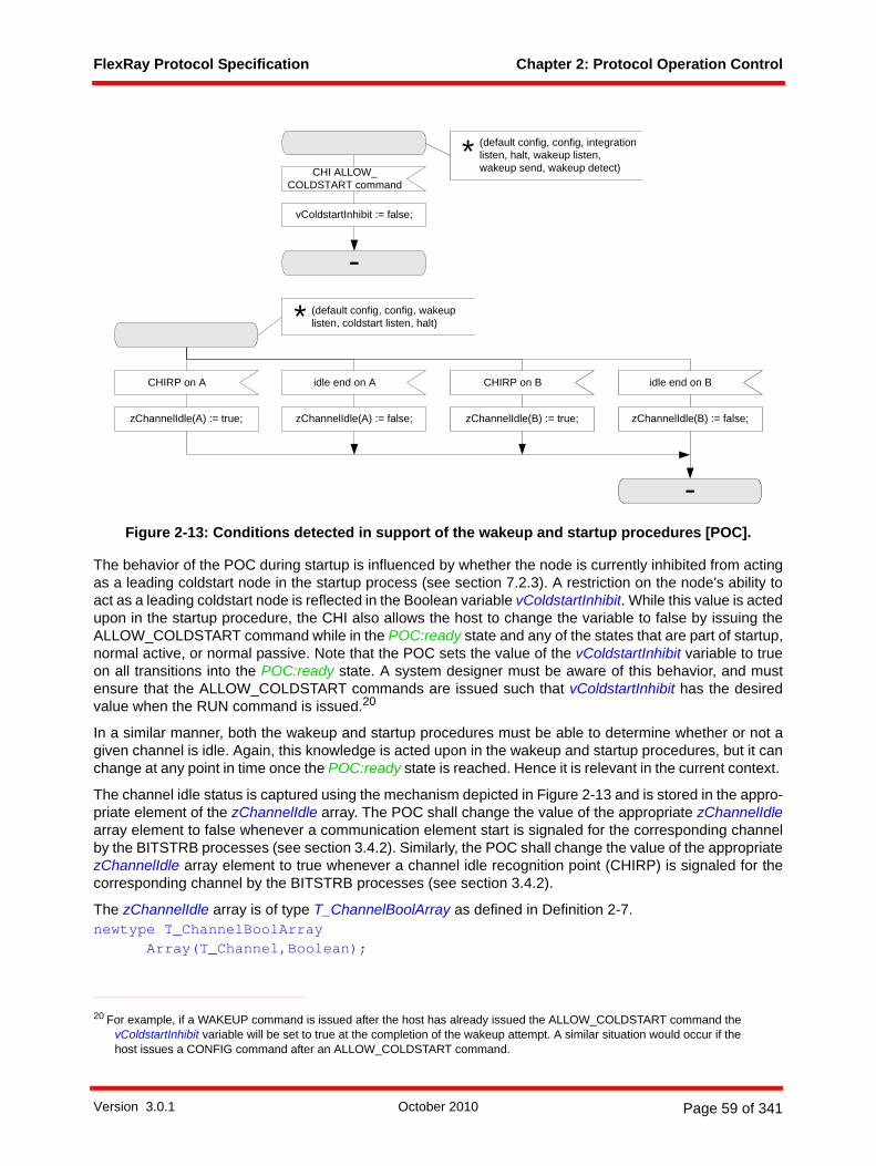
FlexRay Protocol Specification Chapter 2: Protocol Operation Control
Figure 2-13: Conditions detected in support of the wakeup and startup procedures [POC].
The behavior of the POC during startup is influenced by whether the node is currently inhibited from actingas a leading coldstart node in the startup process (see section 7.2.3). A restriction on the node's ability toact as a leading coldstart node is reflected in the Boolean variable vColdstartInhibit. While this value is actedupon in the startup procedure, the CHI also allows the host to change the variable to false by issuing theALLOW_COLDSTART command while in the POC:ready state and any of the states that are part of startup,normal active, or normal passive. Note that the POC sets the value of the vColdstartInhibit variable to trueon all transitions into the POC:ready state. A system designer must be aware of this behavior, and mustensure that the ALLOW_COLDSTART commands are issued such that vColdstartInhibit has the desiredvalue when the RUN command is issued.20
In a similar manner, both the wakeup and startup procedures must be able to determine whether or not agiven channel is idle. Again, this knowledge is acted upon in the wakeup and startup procedures, but it canchange at any point in time once the POC:ready state is reached. Hence it is relevant in the current context.
The channel idle status is captured using the mechanism depicted in Figure 2-13 and is stored in the appro-priate element of the zChannelIdle array. The POC shall change the value of the appropriate zChannelIdlearray element to false whenever a communication element start is signaled for the corresponding channelby the BITSTRB processes (see section 3.4.2). Similarly, the POC shall change the value of the appropriatezChannelIdle array element to true whenever a channel idle recognition point (CHIRP) is signaled for thecorresponding channel by the BITSTRB processes (see section 3.4.2).
The zChannelIdle array is of type T_ChannelBoolArray as defined in Definition 2-7.newtype T_ChannelBoolArray
Array(T_Channel,Boolean);
20 For example, if a WAKEUP command is issued after the host has already issued the ALLOW_COLDSTART command the vColdstartInhibit variable will be set to true at the completion of the wakeup attempt. A similar situation would occur if the host issues a CONFIG command after an ALLOW_COLDSTART command.
CHI ALLOW_COLDSTART command
-
CHIRP on A idle end on A CHIRP on B
-
zChannelIdle(A) := true; zChannelIdle(A) := false; zChannelIdle(B) := true;
vColdstartInhibit := false;
(default config, config, wakeup listen, coldstart listen, halt) *
(default config, config, integration listen, halt, wakeup listen, wakeup send, wakeup detect)
*
idle end on B
zChannelIdle(B) := false;
Version 3.0.1 October 2010 Page 59 of 341
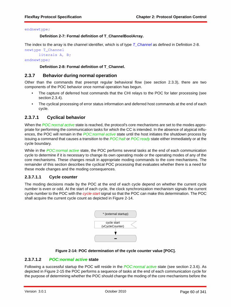
FlexRay Protocol Specification Chapter 2: Protocol Operation Control
endnewtype;
Definition 2-7: Formal definition of T_ChannelBoolArray.
The index to the array is the channel identifier, which is of type T_Channel as defined in Definition 2-8.newtype T_Channel
literals A, B;endnewtype;
Definition 2-8: Formal definition of T_Channel.
2.3.7 Behavior during normal operationOther than the commands that preempt regular behavioral flow (see section 2.3.3), there are twocomponents of the POC behavior once normal operation has begun.
• The capture of deferred host commands that the CHI relays to the POC for later processing (seesection 2.3.4).
• The cyclical processing of error status information and deferred host commands at the end of eachcycle.
2.3.7.1 Cyclical behaviorWhen the POC:normal active state is reached, the protocol's core mechanisms are set to the modes appro-priate for performing the communication tasks for which the CC is intended. In the absence of atypical influ-ences, the POC will remain in the POC:normal active state until the host initiates the shutdown process byissuing a command that causes a transition to the POC:halt or POC:ready state either immediately or at thecycle boundary.
While in the POC:normal active state, the POC performs several tasks at the end of each communicationcycle to determine if it is necessary to change its own operating mode or the operating modes of any of thecore mechanisms. These changes result in appropriate moding commands to the core mechanisms. Theremainder of this section describes the cyclical POC processing that evaluates whether there is a need forthese mode changes and the moding consequences.
2.3.7.1.1 Cycle counterThe moding decisions made by the POC at the end of each cycle depend on whether the current cyclenumber is even or odd. At the start of each cycle, the clock synchronization mechanism signals the currentcycle number to the POC with the cycle start signal so that the POC can make this determination. The POCshall acquire the current cycle count as depicted in Figure 2-14.
Figure 2-14: POC determination of the cycle counter value [POC].
2.3.7.1.2 POC:normal active stateFollowing a successful startup the POC will reside in the POC:normal active state (see section 2.3.6). Asdepicted in Figure 2-15 the POC performs a sequence of tasks at the end of each communication cycle forthe purpose of determining whether the POC should change the moding of the core mechanisms before the
-
cycle start(vCycleCounter)
* (external startup)
Version 3.0.1 October 2010 Page 60 of 341
FlexRay Protocol Specification Chapter 2: Protocol Operation Control
beginning of the next communication cycle. The CSP process (see Figure 8-6) signals the completion of theclock correction calculation to the POC using the SyncCalcResult signal. This signal results in the following:
1. If vPOC!SlotMode is ALL_PENDING, the POC shall change its value to ALL and enable all frame transmissions by moding MAC to ALL for both channels. This completes the POC's reaction to the ALL_SLOTS command received asynchronously during the preceding cycle (see section 2.3.4.2).
2. The POC then performs a sequence of error checking tasks whose outcome determines the subse-quent behavior. This task sequence is represented by the invocation of the NORMAL_ERROR_CHECK macro in Figure 2-15. The details of this task sequence are described in section 2.3.7.1.4.2. As a result the POC will be in one of the following states:
a. If the vPOC!ErrorMode is ACTIVE and the CHI did not relay a DEFERRED_HALT or aDEFERRED_READY command to the POC in the preceding communication cycle (see section2.3.4.1), the POC shall remain in the POC:normal active state.
b. If the vPOC!ErrorMode is PASSIVE and the CHI did not relay a DEFERRED_HALT or aDEFERRED_READY command to the POC in the preceding communication cycle (see section2.3.4.1), the POC shall mode the MAC and CSP to halt frame transmission and transition to thePOC:normal passive state.
c. If vPOC!ErrorMode is COMM_HALT the POC shall halt the execution of the core mechanisms bymoding them to STANDBY and transition to the POC:halt state.
d. If the CHI did relay a DEFERRED_HALT command to the POC in the preceding communicationcycle (see section 2.3.4.1), the POC shall stop the execution of the core mechanisms by modingthem to STANDBY and transition to the POC:halt state.
e. If the CHI did relay a DEFERRED_READY command to the POC in the preceding communicationcycle (see section 2.3.4.1), the POC shall stop the execution of the core mechanisms by modingthem to STANDBY and transition to the POC:ready state.
Version 3.0.1 October 2010 Page 61 of 341

FlexRay Protocol Specification Chapter 2: Protocol Operation Control
Figure 2-15: Cyclical behavior in the POC:normal active state [POC].21
2.3.7.1.3 POC:normal passive stateThe POC's behavior in the POC:normal passive state is analogous its behavior in the POC:normal activestate (see section 2.3.7.1.2). As depicted in Figure 2-16 the POC performs a sequence of tasks at the endof each communication cycle for the purpose of determining whether the POC should change the modingof the core mechanisms before the beginning of the next communication cycle. The CSP process (seeFigure 8-6) signals the completion of the clock correction calculation to the POC using the SyncCalcResultsignal. This signal results in the following:
1. If vPOC!SlotMode is ALL_PENDING, the POC shall change its value to ALL and enable all frame transmissions by moding Media Access Control process to ALL for both channels. This completes the POC's reaction to the ALL_SLOTS command received asynchronously during the preceding cycle (see section 2.3.4.2).
2. The POC then performs a sequence of error checking tasks whose outcome determines the subse-quent behavior. This task sequence is represented by the invocation of the PASSIVE_ERROR_CHECK macro in Figure 2-16. The details of this task sequence are described in section 2.3.7.1.4.3. As a result the POC will be in one of the following states:
21 zStartupX is zStartupNodes in even cycles and zRxStartupPairs in odd cycles. zRefX is zRefNode in even cycles and zRefPair in odd cycles. See Figure 8-6 for details.
normal active
halt
vPOC!SlotMode ?
vPOC!SlotMode := ALL;
ALL_PENDING
else
HALT
NORMAL_ERROR_CHECK PASSIVE
normal passive
ACTIVE
PROTOCOL_ENGINE_HALT
MAC control on A (ALL),MAC control on B (ALL)
vPOC!State := HALT;
MAC control on A (NOCE),MAC control on B (NOCE),CSP control (NOSYNC),EXP sync state (PASSIVE)
vAllowPassiveToActive :=0;vPOC!State := NORMAL_PASSIVE;’update vAllowPassiveToActive in CHI’;’update vPOC in CHI’;’update vClockCorrectionFailed in CHI’;
’update vPOC in CHI’;’update vClock-
CorrectionFailed in CHI’;
SyncCalcResult(zSyncCalcResult, zStartupX, zRefX)
ready
READY
PROTOCOL_ENGINE_READY
EXP sync state (ACTIVE)
Version 3.0.1 October 2010 Page 62 of 341
FlexRay Protocol Specification Chapter 2: Protocol Operation Control
a. If the vPOC!ErrorMode is ACTIVE and the CHI did not relay a DEFERRED_HALT or aDEFERRED_READY command to the POC in the preceding communication cycle (see section2.3.4.1), the POC shall mode the MAC and CSP mechanisms to support resumption of frame trans-mission based on whether the node is a sync node (pKeySlotUsedForSync is true) and whether thenode is currently in key slot only mode, and then transition to the POC:normal active state.
b. If the vPOC!ErrorMode is PASSIVE and the CHI did not relay a DEFERRED_HALT or aDEFERRED_READY command to the POC in the preceding communication cycle (see section2.3.4.1), the POC shall remain in to the POC:normal passive state.
c. If vPOC!ErrorMode is COMM_HALT the POC shall stop the execution of the core mechanisms bymoding them to STANDBY and transition to the POC:halt state.
d. If the CHI did relay a DEFERRED_HALT command to the POC in the preceding communicationcycle (see section 2.3.4.1), the POC shall stop the execution of the core mechanisms by modingthem to STANDBY and transition to the POC:halt state.
e. If the CHI did relay a DEFERRED_READY command to the POC in the preceding communicationcycle (see section 2.3.4.1), the POC shall stop the execution of the core mechanisms by modingthem to STANDBY and transition to the POC:ready state.
Version 3.0.1 October 2010 Page 63 of 341
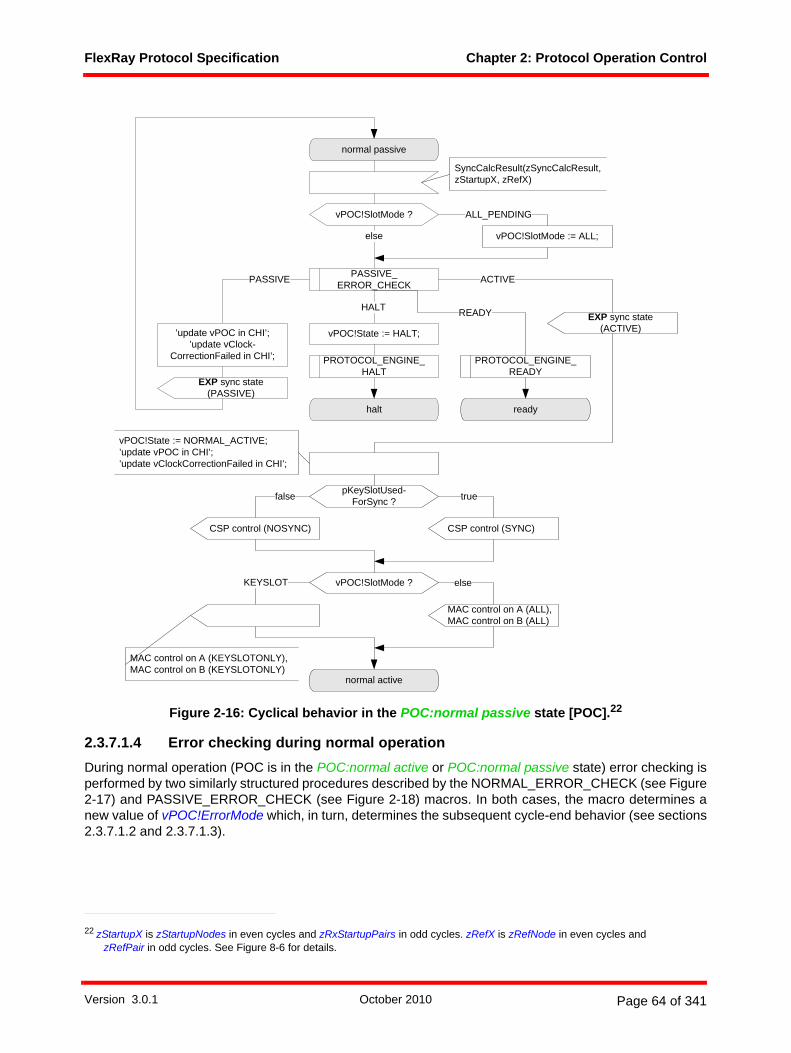
FlexRay Protocol Specification Chapter 2: Protocol Operation Control
Figure 2-16: Cyclical behavior in the POC:normal passive state [POC].22
2.3.7.1.4 Error checking during normal operationDuring normal operation (POC is in the POC:normal active or POC:normal passive state) error checking isperformed by two similarly structured procedures described by the NORMAL_ERROR_CHECK (see Figure2-17) and PASSIVE_ERROR_CHECK (see Figure 2-18) macros. In both cases, the macro determines anew value of vPOC!ErrorMode which, in turn, determines the subsequent cycle-end behavior (see sections2.3.7.1.2 and 2.3.7.1.3).
22 zStartupX is zStartupNodes in even cycles and zRxStartupPairs in odd cycles. zRefX is zRefNode in even cycles and zRefPair in odd cycles. See Figure 8-6 for details.
EXP sync state (PASSIVE)
EXP sync state (ACTIVE)
normal passive
halt
vPOC!SlotMode ?
vPOC!SlotMode := ALL;
ALL_PENDING
else
HALT
PASSIVE_ERROR_CHECK ACTIVE
normal active
PASSIVE
vPOC!State := HALT;
PROTOCOL_ENGINE_HALT
CSP control (SYNC)CSP control (NOSYNC)
vPOC!SlotMode ?
MAC control on A (ALL),MAC control on B (ALL)
elseKEYSLOT
false
MAC control on A (KEYSLOTONLY),MAC control on B (KEYSLOTONLY)
pKeySlotUsed-ForSync ? true
’update vPOC in CHI’;’update vClock-
CorrectionFailed in CHI’;
vPOC!State := NORMAL_ACTIVE;’update vPOC in CHI’;’update vClockCorrectionFailed in CHI’;
SyncCalcResult(zSyncCalcResult, zStartupX, zRefX)
ready
PROTOCOL_ENGINE_READY
READY
Version 3.0.1 October 2010 Page 64 of 341

FlexRay Protocol Specification Chapter 2: Protocol Operation Control
2.3.7.1.4.1 Error checking overview
At the end of each communication cycle CSP communicates the error consequences of the clock synchro-nization mechanism's rate and offset calculations. In the SDL this is accomplished with the SyncCalcResultsignal whose first argument, zSyncCalcResult, assumes one of three values:
1. WITHIN_BOUNDS indicates that the calculations resulted in no errors.2. MISSING_TERM indicates that either the rate or offset correction could not be calculated.3. EXCEEDS_BOUNDS indicates that either the rate or offset correction term calculated was deemed
too large when compared to the calibrated limits.
The consequences of the EXCEEDS_BOUNDS value are processed in every cycle. The other two resultsare only processed at the end of odd cycles.
The error checking behavior is detailed in sections 2.3.7.1.4.2 and 2.3.7.1.4.3. A number of configurationalternatives and the need to verify cycle timing before resuming communication influence the detailed errorchecking behavior. However, the basic concept can be grasped by considering the behavior in the absenceof these considerations. In the absence of these influences, the processing path is determined by the valueof zSyncCalcResult as follows:
1. In all cycles (even or odd), zSyncCalcResult = EXCEEDS_BOUNDS causes the POC to transition to the POC:halt state.
2. In odd cycles, zSyncCalcResult = WITHIN_BOUNDS causes the POC to stay in, or transition to, the POC:normal active state.
3. In odd cycles, if zSyncCalcResult = MISSING_TERM
a. The POC will transition to the POC:halt state if the MISSING_TERM value has persisted for at leastgMaxWithoutClockCorrectionFatal odd cycles.
b. The POC will transition to (or remain in) the POC:normal passive state if the MISSING_TERM valuehas persisted for at least gMaxWithoutClockCorrectionPassive, but less than gMaxWithoutClock-CorrectionFatal odd cycles.
c. Otherwise the POC stays in the POC:normal active state.
2.3.7.1.4.2 Error checking details for the POC:normal active state
The zSyncCalcResult value obtained from CSP is used to determine the new vPOC!ErrorMode as depictedin Figure 2-17.
1. If zSyncCalcResult is WITHIN_BOUNDS, the vPOC!ErrorMode remains ACTIVE.2. If zSyncCalcResult is EXCEEDS_BOUNDS:
a. If the node is configured to allow communication to be halted due to severe clock calculation errors(pAllowHaltDueToClock is true), then the vPOC!ErrorMode is set to COMM_HALT.
b. If the node is configured not to allow communication to be halted due to severe clock calculationerrors (pAllowHaltDueToClock is false), then the vPOC!ErrorMode is set to PASSIVE.
3. If zSyncCalcResult is MISSING_TERM and the cycle is even, the condition is ignored and vPOC!ErrorMode remains ACTIVE.
4. If zSyncCalcResult is MISSING_TERM and the cycle is odd the behavior is determined by how many consecutive odd cycles (vClockCorrectionFailed) have yielded MISSING_TERM.
a. If vClockCorrectionFailed < gMaxWithoutClockCorrectionPassive, then the vPOC!ErrorModeremains ACTIVE.
b. If gMaxWithoutClockCorrectionPassive <= vClockCorrectionFailed < gMaxWithoutClockCorrection-Fatal, then the vPOC!ErrorMode is set to PASSIVE.
c. If vClockCorrectionFailed >= gMaxWithoutClockCorrectionFatal and
Version 3.0.1 October 2010 Page 65 of 341
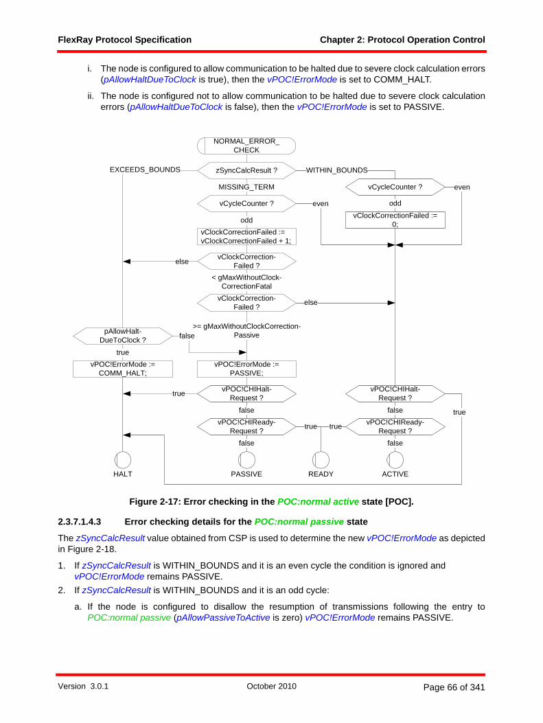
FlexRay Protocol Specification Chapter 2: Protocol Operation Control
i. The node is configured to allow communication to be halted due to severe clock calculation errors(pAllowHaltDueToClock is true), then the vPOC!ErrorMode is set to COMM_HALT.
ii. The node is configured not to allow communication to be halted due to severe clock calculationerrors (pAllowHaltDueToClock is false), then the vPOC!ErrorMode is set to PASSIVE.
Figure 2-17: Error checking in the POC:normal active state [POC].
2.3.7.1.4.3 Error checking details for the POC:normal passive state
The zSyncCalcResult value obtained from CSP is used to determine the new vPOC!ErrorMode as depictedin Figure 2-18.
1. If zSyncCalcResult is WITHIN_BOUNDS and it is an even cycle the condition is ignored and vPOC!ErrorMode remains PASSIVE.
2. If zSyncCalcResult is WITHIN_BOUNDS and it is an odd cycle:
a. If the node is configured to disallow the resumption of transmissions following the entry toPOC:normal passive (pAllowPassiveToActive is zero) vPOC!ErrorMode remains PASSIVE.
vClockCorrection-Failed ?
MISSING_TERM
PASSIVE
pAllowHalt-DueToClock ?
ACTIVE
else
>= gMaxWithoutClockCorrection-Passive
vClockCorrection-Failed ?
zSyncCalcResult ?
HALT
< gMaxWithoutClock-CorrectionFatal
vClockCorrectionFailed :=vClockCorrectionFailed + 1;
EXCEEDS_BOUNDS
NORMAL_ERROR_CHECK
WITHIN_BOUNDS
false
truevPOC!ErrorMode :=
COMM_HALT;vPOC!ErrorMode :=
PASSIVE;
vCycleCounter ?
odd
false
vClockCorrectionFailed := 0;
vCycleCounter ?
odd
even
else
even
vPOC!CHIHalt-Request ?
vPOC!CHIHalt-Request ?
vPOC!CHIReady-Request ?
vPOC!CHIReady-Request ?
false false
true
READY
true
false
true
true
Version 3.0.1 October 2010 Page 66 of 341
FlexRay Protocol Specification Chapter 2: Protocol Operation Control
b. If the node is configured to allow the resumption of transmissions following the entry to POC:normalpassive (pAllowPassiveToActive is non-zero) the behavior is determined by how many consecutiveodd cycles have yielded WITHIN_BOUNDS.
i. If less than pAllowPassiveToActive consecutive odd cycles have yielded WITHIN_BOUNDS,then the vPOC!ErrorMode remains PASSIVE.
ii. If at least pAllowPassiveToActive consecutive odd cycles have yielded WITHIN_BOUNDS, thevPOC!ErrorMode depends on the number (zStartupX) of startup frame pairs observed in thepreceding double cycle.
A. If the node has seen more than one startup frame pair (zStartupX > 1) then thevPOC!ErrorMode is set to ACTIVE.
B. If the node has seen only one startup frame pair (zStartupX = 1) and if the node is a coldstartnode (pKeySlotUsedForStartup = true) then the vPOC!ErrorMode is set to ACTIVE.
C. If neither of the preceding two conditions is met then the vPOC!ErrorMode remains PASSIVE.3. If zSyncCalcResult is EXCEEDS_BOUNDS:
a. If the node is configured to allow communication to be halted due to severe clock calculation errors(pAllowHaltDueToClock is true), then the vPOC!ErrorMode is set to COMM_HALT.
b. If the node is configured not to allow communication to be halted due to severe clock calculationerrors (pAllowHaltDueToClock is false), then the vPOC!ErrorMode remains PASSIVE.
4. If zSyncCalcResult is MISSING_TERM and the cycle is even, the condition is ignored and vPOC!ErrorMode remains PASSIVE.
5. If zSyncCalcResult is MISSING_TERM and the cycle is odd, then the behavior is determined by how many consecutive odd cycles have yielded MISSING_TERM.
a. If at least gMaxWithoutClockCorrectionFatal consecutive odd cycles have yielded MISSING_TERM,and
i. The node is configured to allow communication to be halted due to severe clock calculation errors(pAllowHaltDueToClock is true), then the vPOC!ErrorMode is set to COMM_HALT.
ii. The node is configured not to allow communication to be halted due to severe clock calculationerrors (pAllowHaltDueToClock is false), then the vPOC!ErrorMode remains PASSIVE.
b. If less than gMaxWithoutClockCorrectionFatal consecutive odd cycles have yieldedMISSING_TERM then the vPOC!ErrorMode remains PASSIVE.
Version 3.0.1 October 2010 Page 67 of 341

FlexRay Protocol Specification Chapter 2: Protocol Operation Control
Figure 2-18: Error checking in the POC:normal passive state [POC].23
23 zStartupX is zStartupNodes in even cycles and zRxStartupPairs in odd cycles. zRefX is zRefNode in even cycles and zRefPair in odd cycles. See Figure 8-6 for details.
true
vClockCorrection-Failed ?
< gMaxWithoutClock-CorrectionFatal - 1
vClockCorrectionFailed :=vClockCorrectionFailed + 1;
pAllowHalt-DueToClock ?
true
else
HALT
zStartupX ?
false
pKeySlotUsed-ForStartup ?
=1
>1
vAllowPassive-ToActive ?
= pAllowPassiveToActive - 1
vClockCorrectionFailed := 0;
WITHIN_BOUNDSzSyncCalcResult ?
ACTIVE
PASSIVE_ERROR_CHECK
MISSING_TERM
PASSIVE
EXCEEDS_BOUNDS
=0
=0
false
vPOC!ErrorMode := COMM_HALT;
vPOC!ErrorMode := ACTIVE;
vAllowPassiveToActive :=vAllowPassiveToActive + 1;
vAllowPassiveToActive :=0; else
vCycleCounter ?
odd
pAllowPassive-ToActive ?
else
vCycleCounter ?even
odd
’update vAllow-PassiveToActive in CHI’;
vPOC!CHIHalt-Request ?
vPOC!CHIHalt-Request ?
vPOC!CHIReady-Request ?
vPOC!CHIReady-Request ?
false false
true
true
truetrue
READY
false false
even
Version 3.0.1 October 2010 Page 68 of 341
FlexRay Protocol Specification Chapter 3: Coding and Decoding
Chapter 3Coding and Decoding
This chapter defines how the node performs frame and symbol coding and decoding.
3.1 PrinciplesThis chapter describes the coding and decoding behavior of the TxD, RxD, and TxEN interface signalsbetween the communication controller and the bus driver.
A node may support up to two independent physical layer channels, identified as channel A and channel B.Refer to section 1.12.4 for additional information on the interface between the CC and the BD. Thedescription in this chapter assumes a physical layer that appears to the protocol engine as a binary mediumwith two distinct levels, called HIGH and LOW.24 A bit stream generated from these two levels is called acommunication element (CE).
A node shall use a non-return to zero (NRZ) signaling method for coding and decoding of a CE. This meansthat the generated bit level is either LOW or HIGH during the entire bit time gdBit.
The node processes bit streams present on the physical media, extracts frame and symbol information, andpasses this information to the relevant FlexRay processes.
3.2 DescriptionIn order to support two channels each node must implement two sets of independent coding and decodingprocesses, one for channel A and another for channel B. The subsequent paragraphs of this chapter specifythe function of the coding and decoding for channel A. It is assumed that whenever a channel-specificprocess is defined for channel A there is another, essentially identical, process defined for channel B, eventhough this process is not explicitly described in the specification.The description of the coding anddecoding behavior is contained in three processes. These processes are the main coding and decodingprocess (CODEC) and the following two sub-processes:
1. Bit strobing process (BITSTRB).2. Wakeup pattern decoding process (WUPDEC).
The POC is responsible for creating the CODEC process before entering the POC:ready state. Once instan-tiated, the CODEC process is responsible for creating and terminating the subprocesses. The POC isresponsible for sending a signal that causes a termination of the CODEC process. If the CODEC processis not executing (i.e., if it has not yet been instantiated or if it has been terminated) the TxEN and TxDoutputs shall be HIGH.25
The relationships between the coding/decoding and the other core mechanisms are depicted in Figure 3-126.
24 Detailed bus state definitions may be found in the appropriate physical layer specification ([EPL10], for example).25 When a dual channel device is configured to operate in a single channel mode, the internal TxEN and TxD signals must be
driven high on the unused channel. This requirement applies whenever the internal signals TxEN and TxD are connected to the external signals TxEN_external and TxD_external (see section 1.12.4).
26 The dark lines represent data flows between mechanisms that are relevant to this chapter. The lighter gray lines are relevant to the protocol, but not to this chapter.
Version 3.0.1 October 2010 Page 69 of 341

FlexRay Protocol Specification Chapter 3: Coding and Decoding
Figure 3-1: Coding / Decoding context.
3.2.1 Frame and symbol encodingThis section specifies the behavior of the mechanisms used by the node to encode the communicationelements into a bit stream and how the transmitting node represents this bit stream to the bus driver forcommunication onto the physical media.
3.2.1.1 Frame encoding
3.2.1.1.1 Transmission start sequenceThe transmission start sequence (TSS) is used to initiate proper connection setup through the network. Atransmitting node generates a TSS that consists of a continuous LOW for a period given by the parametergdTSSTransmitter.
frame and symbolprocessing
media accesscontrol
clock synchronization
startup
macrotickgeneration
clock synchronization
processing
protocoloperation
control
controllerhost interface
coding / decoding processeschannel A
frame and symbolprocessingchannel A
media accesscontrol
channel A
clock synchronization
startup channel A
to channel interface from channel interface
to / from host
media accesscontrolchannel B
coding / decodingprocesseschannel B
frame and symbolprocessingchannel B
clock synchronization
startup channel B
Version 3.0.1 October 2010 Page 70 of 341

FlexRay Protocol Specification Chapter 3: Coding and Decoding
The purpose of the TSS is to mark the beginning of a transmission and to set up the path between the trans-mitter and receiver. This includes setting up the input and output connections of an active star as well asallowing the receiving bus driver the time necessary to realize that the bus is no longer idle. Further, theactive low portion of the TSS allows a transmitting BD to actually begin transmission (since the BD will notactually begin transmitting after TxEN is activated until TxD is commanding an active low). During this setup, active stars and bus drivers truncate a number of bits at the beginning of a communication element. TheTSS prevents the content of the frame or symbol27 from being truncated.
3.2.1.1.2 Frame start sequenceThe frame start sequence (FSS) is used to compensate for a possible quantization error in the first byte startsequence after the TSS. The FSS shall consist of one HIGH gdBit time. The node shall append an FSS tothe bit stream immediately following the TSS of a transmitted frame.
3.2.1.1.3 Byte start sequenceThe byte start sequence (BSS) is used to provide bit stream timing information to the receiving devices. TheBSS shall consist of one HIGH gdBit time followed by one LOW gdBit time. Each byte of frame data shallbe sent on the channel as an extended byte sequence that consists of one BSS followed by eight data bits.
3.2.1.1.4 Frame end sequenceThe frame end sequence (FES) is used to mark the end of the last byte sequence of a frame. The FES shallconsist of one LOW gdBit time followed by one HIGH gdBit time. The node shall append an FES to the bitstream immediately after the last extended byte sequence of the frame.
For frames transmitted in the static segment the second bit of the FES is the last bit in the transmitted bitstream. As a result, the transmitting node shall set the TxEN signal to HIGH at the end of the second bit ofthe FES.
For frames transmitted in the dynamic segment the FES is followed by the dynamic trailing sequence (seebelow).
3.2.1.1.5 Dynamic trailing sequenceThe dynamic trailing sequence (DTS), which is only used for frames transmitted in the dynamic segment, isused to indicate the exact point in time of the transmitter's minislot action point28 and prevents prematurechannel idle detection29 by the receivers. When transmitting a frame in the dynamic segment the node shalltransmit a DTS immediately after the FES of the frame.
The DTS consists of two parts - a variable-length period with the TxD output at the LOW level, followed bya fixed-length period with the TxD output at the HIGH level. The minimum length of the LOW period is onegdBit. After this minimum length the node leaves the TxD output at the LOW level until the next minislotaction point. At the next minislot action point the node shall switch the TxD output to the HIGH level, andthe node shall switch the TxEN output to the HIGH level after a delay of 1 gdBit after the minislot actionpoint30. The duration of a DTS is variable and can assume any value between 2 gdBit (for a DTS composedof 1 gdBit LOW and 1 gdBit HIGH), and gdMinislot + 2 gdBit (if the DTS starts slightly later than one gdBitbefore a minislot action point).
Note that the processes defining the behavior of the CODEC do not have any direct knowledge of theminislot action point - those processes are informed of the appropriate time to end the generation of the DTSby the signal stop transmission on A sent by the MAC process.
27 Note that a TSS is not used before transmission of a WUS or WUDOP because those symbols begin with a sufficiently long active low phase to achieve these goals.
28 See also Chapter 5.29 See also section 3.2.5.30 This ensures that there is a period of one gdBit during which the TxD output is at the HIGH level prior to the transition of TxEN
output to the HIGH level. This is required for the stability of certain types of physical layers.
Version 3.0.1 October 2010 Page 71 of 341
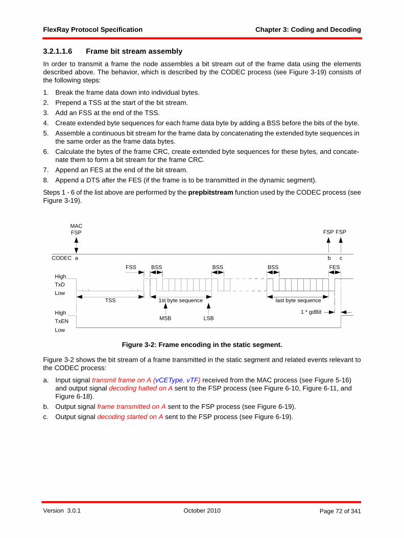
FlexRay Protocol Specification Chapter 3: Coding and Decoding
3.2.1.1.6 Frame bit stream assembly In order to transmit a frame the node assembles a bit stream out of the frame data using the elementsdescribed above. The behavior, which is described by the CODEC process (see Figure 3-19) consists ofthe following steps:
1. Break the frame data down into individual bytes.2. Prepend a TSS at the start of the bit stream.3. Add an FSS at the end of the TSS.4. Create extended byte sequences for each frame data byte by adding a BSS before the bits of the byte. 5. Assemble a continuous bit stream for the frame data by concatenating the extended byte sequences in
the same order as the frame data bytes.6. Calculate the bytes of the frame CRC, create extended byte sequences for these bytes, and concate-
nate them to form a bit stream for the frame CRC.7. Append an FES at the end of the bit stream.8. Append a DTS after the FES (if the frame is to be transmitted in the dynamic segment).
Steps 1 - 6 of the list above are performed by the prepbitstream function used by the CODEC process (seeFigure 3-19).
Figure 3-2: Frame encoding in the static segment.
Figure 3-2 shows the bit stream of a frame transmitted in the static segment and related events relevant tothe CODEC process:
a. Input signal transmit frame on A (vCEType, vTF) received from the MAC process (see Figure 5-16) and output signal decoding halted on A sent to the FSP process (see Figure 6-10, Figure 6-11, and Figure 6-18).
b. Output signal frame transmitted on A sent to the FSP process (see Figure 6-19).c. Output signal decoding started on A sent to the FSP process (see Figure 6-19).
FSS
TSS
High
LowTxD
1st byte sequence last byte sequence
High
LowTxEN MSB LSB
BSS
1 * gdBit
a c
BSS FES
MACFSP
CODEC
FSP
BSS
b
FSP
Version 3.0.1 October 2010 Page 72 of 341

FlexRay Protocol Specification Chapter 3: Coding and Decoding
Figure 3-3: Frame encoding in the dynamic segment.
Figure 3-3 shows the bit stream of a frame transmitted in the dynamic segment and related events relevantto the CODEC process:
a. Input signal transmit frame on A (vCEType, vTF) received from the MAC process (see Figure 5-22) and output signal decoding halted on A sent to the FSP process (see Figure 6-10, Figure 6-11, and Figure 6-18).
b. Output signal frame transmitted on A sent to the FSP process (see Figure 6-19).c. Output signal DTS start on A sent to the MAC process (see Figure 5-22).d. Input signal stop transmission on A received from the MAC process (see Figure 5-22).e. Output signal decoding started on A sent to the FSP process (see Figure 6-19).
3.2.1.2 Symbol encodingThe FlexRay communication protocol defines four symbols that are represented by three distinct symbol bitpatterns:
1. Pattern 1 = Collision Avoidance Symbol31 (CAS) and Media Access Test Symbol (MTS).2. Pattern 2 = Wakeup Symbol (WUS).3. Pattern 3 = Wakeup During Operation Pattern (WUDOP).
The node shall encode the MTS and CAS in exactly the same manner. Receivers distinguish between thesesymbols based on the node's protocol status. The encoding process does not distinguish between thesetwo symbols. The bit streams for each of the symbols are described in the subsequent sections.
3.2.1.2.1 Collision avoidance symbol and media access test symbolThe node shall transmit these symbols starting with the TSS, followed by a LOW level with a duration ofcdCAS as shown in Figure 3-4. The node shall transmit these symbols with the edges of the TxEN signalbeing synchronous with the TxD at the start of transmission, and with TxD returning to high after a delayperiod (defined by the parameter cdStaggerDelay) following the point that the TxEN signal returns to highat the end of transmission. For details refer to Figure 3-18 and Figure 3-24.32
31 See also Chapter 7.
FSS
TSS
High
LowTxD
1st byte sequence
FES
last byte sequence
High
LowTxEN MSB LSB
1 * gdBit
DTSa ec
BSSBSS
FSP
CODEC d
MAC MACMACFSP
BSS
b
FSP
Version 3.0.1 October 2010 Page 73 of 341
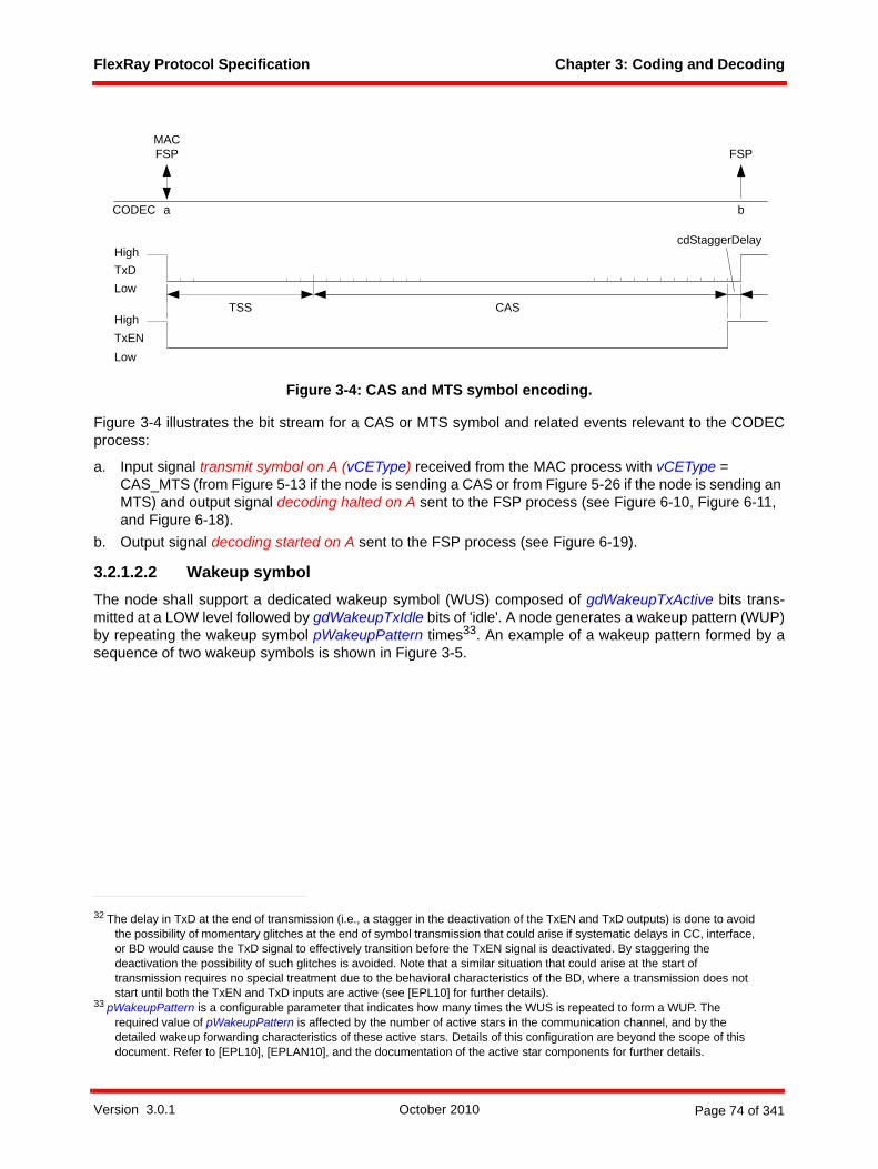
FlexRay Protocol Specification Chapter 3: Coding and Decoding
Figure 3-4: CAS and MTS symbol encoding.
Figure 3-4 illustrates the bit stream for a CAS or MTS symbol and related events relevant to the CODECprocess:
a. Input signal transmit symbol on A (vCEType) received from the MAC process with vCEType = CAS_MTS (from Figure 5-13 if the node is sending a CAS or from Figure 5-26 if the node is sending an MTS) and output signal decoding halted on A sent to the FSP process (see Figure 6-10, Figure 6-11, and Figure 6-18).
b. Output signal decoding started on A sent to the FSP process (see Figure 6-19).
3.2.1.2.2 Wakeup symbolThe node shall support a dedicated wakeup symbol (WUS) composed of gdWakeupTxActive bits trans-mitted at a LOW level followed by gdWakeupTxIdle bits of 'idle'. A node generates a wakeup pattern (WUP)by repeating the wakeup symbol pWakeupPattern times33. An example of a wakeup pattern formed by asequence of two wakeup symbols is shown in Figure 3-5.
32 The delay in TxD at the end of transmission (i.e., a stagger in the deactivation of the TxEN and TxD outputs) is done to avoid the possibility of momentary glitches at the end of symbol transmission that could arise if systematic delays in CC, interface, or BD would cause the TxD signal to effectively transition before the TxEN signal is deactivated. By staggering the deactivation the possibility of such glitches is avoided. Note that a similar situation that could arise at the start of transmission requires no special treatment due to the behavioral characteristics of the BD, where a transmission does not start until both the TxEN and TxD inputs are active (see [EPL10] for further details).
33 pWakeupPattern is a configurable parameter that indicates how many times the WUS is repeated to form a WUP. The required value of pWakeupPattern is affected by the number of active stars in the communication channel, and by the detailed wakeup forwarding characteristics of these active stars. Details of this configuration are beyond the scope of this document. Refer to [EPL10], [EPLAN10], and the documentation of the active star components for further details.
CAS
High
LowTxD
High
LowTxEN
TSS
a bCODEC
MACFSP FSP
cdStaggerDelay
Version 3.0.1 October 2010 Page 74 of 341

FlexRay Protocol Specification Chapter 3: Coding and Decoding
Figure 3-5: Wakeup pattern consisting of two wakeup symbols.
Figure 3-5 shows the bit stream of a wakeup pattern and related events relevant to the CODEC process:
a. Input signal transmit symbol on A (vCEType) received from the POC process with vCEType = WUP (see Figure 7-4).
b. Output signal WUP transmitted on A sent to the POC process (see Figure 7-4).
The node shall transmit a WUS with the edges of the TxEN signal being synchronous to the TxD at the startof the WUS's low phase, and with TxD returning to high after a delay period (defined by the parametercdStaggerDelay) following the point that the TxEN signal returns to high at the start of the WUS's idle phase(which is also the end of the WUS's low phase)34. Note that there is no TSS transmission associated witha WUS. The node must be capable of detecting activity on the channel during gdWakeupTxIdle inside aWUP as shown in Figure 3-6.
34 The purpose of the staggering of the TxD and TxEN is the same as for transmission of the CAS/MTS - to avoid the possibility of glitches when the TxEN output is deactivated.
WUS 1 WUS 2
gdWakeupTxActive
High
LowTxD
High
LowTxEN
a b
POC
CODEC
POC
gdWakeupTxIdle
cdStaggerDelay
Version 3.0.1 October 2010 Page 75 of 341

FlexRay Protocol Specification Chapter 3: Coding and Decoding
Figure 3-6: Wakeup symbol collision and wakeup pattern reception.
Figure 3-6 shows an example bit stream that could result from a wakeup symbol collision and shows relatedevents relevant to the CODEC and WUPDEC processes:35
a. Input signal transmit symbol on A (vCEType) received from the POC process of node 1 with vCEType = WUP (see Figure 7-4).
b. Input signal transmit symbol on A (vCEType) received from the POC process of node 2 with vCEType = WUP (see Figure 7-4).
c. Output signal wakeup collision on A sent from the CODEC process of node 1 to the POC process of node 1 (see Figure 7-4).
d. Output signal wakeup decoded on A sent from the WUPDEC process of node 3 to the POC process (see 3.2.7.2.2) and to the FSP process (see Figure 6-8).
35 In the figure, node 2 transmits a WUP even though node 1 had previously begun transmitting a WUP. This can occur if node 2 does not receive the WUS’s previously sent by node 1. One possible reason that this could occur is that the first several WUS’s of the wakeup pattern were used to wake up a sleeping star positioned between node 1 and node 2. On the other hand, node 3 may receive more of the WUS's sent by node 1 if the path between node 1 and node 3 consumes fewer WUS's than the path between node 1 and node 2.
TxLow = gdWakeupTxActiveTxIdle = gdWakeupTxIdle RxLow = gdWakeupRxLowRxIdle = gdWakeupRxIdleWuCol = cdWakeupMaxCollision
TxEN
d
POCFSP
= WuCol
WUPDEC(3)
TxIdle
TxLow
TxLow
=RxLow >=RxLow >=RxIdle
TxEN
RxD
node 1
node 2
RxD
RxDnode 3
c
POC
CODEC(1)a
POC
CODEC(1)
b
POC
CODEC(2)
gdWakeupRxWindow
bitstrobing disabled
TxLow
TxIdle
bitstrobing blind
=RxIdle
Version 3.0.1 October 2010 Page 76 of 341

FlexRay Protocol Specification Chapter 3: Coding and Decoding
3.2.1.2.3 Wakeup During Operation Pattern (WUDOP)The node shall support the transmission of a Wakeup During Operation Pattern (WUDOP), intended to allowthe node to send a pattern during normal operation that will cause a remote wakeup-capable BD that is inthe low power state to detect a wakeup. The WUDOP consists of a sequence of LOW-HIGH-LOW-HIGH-LOW phases followed by a brief HIGH phase with a duration of a single bit36. The durations of all of thephases except for the last are gdWakeupTxActive bits.
Figure 3-7: Wakeup During Operation Pattern.
Figure 3-7 shows the bit stream of a WUDOP and related events relevant to the CODEC process:
a. Input signal transmit symbol on A (vCEType) received from the MAC process with vCEType = WUDOP (see Figure 5-26) and output signal decoding halted on A sent to the FSP process (see Fig-ure 6-10, Figure 6-11, and Figure 6-18).
b. Output signal decoding started on A sent to the FSP process (see Figure 6-19).
The node shall transmit a WUDOP with the leading edge of the TxEN signal synchronous to the TxD at thestart of the WUDOP's first low phase, and with TxD returning to high one bit time before the TxEN signalreturns to high at the end of the WUDOP. Note that there is no TSS transmission associated with a WUDOP.Also note that before and after the actively transmitted WUDOP, a receiver must see phases of idle on thebus. This is achieved by an appropriate configuration of the symbol window action point (see section B.4.10)and the size of the symbol window (see section B.4.13).
3.2.2 Sampling and majority votingThe node shall perform sampling on the RxD input, i.e., for each channel sample clock period the node shallsample and store the level of the RxD input37. The node shall temporarily store the most recent cVoting-Samples samples of the input.
The node shall perform a majority voting operation on the sampled RxD signal. The purpose of the majorityvoting operation is to filter the RxD signal (the sampled RxD signal is the input and a voted RxD on A signalis the output). The majority voting mechanism is a filter for suppressing glitches (spikes) on the RxD inputsignal. In the context of this chapter a glitch is defined to be an event that changes the current condition ofthe physical layer such that its detected logic state is temporarily forced to a value different than what isbeing sent on the channel by the transmitting node.
36 The single bit of high at the end of the WUDOP is required for idle detection stability of certain types of physical layers.37 CC's that support two channels shall perform the sampling and majority voting operations for both channels. The channels are
independent (i.e., the mechanism results in two sets of voted values, one for channel A and another for channel B).
High
LowTxD
High
LowTxEN
a b
MACFSP
CODEC
FSP
gdWakeupTxActive gdWakeupTxActive gdWakeupTxActive gdWakeupTxActive gdWakeupTxActive
1 * gdBit
Version 3.0.1 October 2010 Page 77 of 341
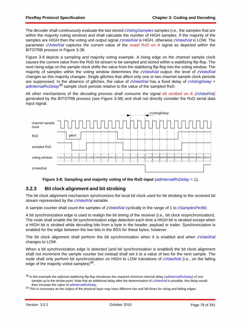
FlexRay Protocol Specification Chapter 3: Coding and Decoding
The decoder shall continuously evaluate the last stored cVotingSamples samples (i.e., the samples that arewithin the majority voting window) and shall calculate the number of HIGH samples. If the majority of thesamples are HIGH then the voting unit output signal zVotedVal is HIGH, otherwise zVotedVal is LOW. Theparameter zVotedVal captures the current value of the voted RxD on A signal as depicted within theBITSTRB process in Figure 3-38.
Figure 3-8 depicts a sampling and majority voting example. A rising edge on the channel sample clockcauses the current value from the RxD bit stream to be sampled and stored within a stabilizing flip-flop. Thenext rising edge on the sample clock shifts the value from the stabilizing flip-flop into the voting window. Themajority of samples within the voting window determines the zVotedVal output; the level of zVotedValchanges as this majority changes. Single glitches that affect only one or two channel sample clock periodsare suppressed. In the absence of glitches, the value of zVotedVal has a fixed delay of cVotingDelay +adInternalRxDelay38 sample clock periods relative to the value of the sampled RxD.
All other mechanisms of the decoding process shall consume the signal bit strobed on A (zVotedVal)generated by the BITSTRB process (see Figure 3-38) and shall not directly consider the RxD serial datainput signal.
Figure 3-8: Sampling and majority voting of the RxD input (adInternalRxDelay = 1).
3.2.3 Bit clock alignment and bit strobingThe bit clock alignment mechanism synchronizes the local bit clock used for bit strobing to the received bitstream represented by the zVotedVal variable.
A sample counter shall count the samples of zVotedVal cyclically in the range of 1 to cSamplesPerBit.
A bit synchronization edge is used to realign the bit timing of the receiver (i.e., bit clock resynchronization).The node shall enable the bit synchronization edge detection each time a HIGH bit is strobed except whena HIGH bit is strobed while decoding bits from a byte in the header, payload or trailer. Synchronization isenabled for the edge between the two bits in the BSS for these bytes, however.
The bit clock alignment shall perform the bit synchronization when it is enabled and when zVotedValchanges to LOW.
When a bit synchronization edge is detected (and bit synchronization is enabled) the bit clock alignmentshall not increment the sample counter but instead shall set it to a value of two for the next sample. Thenode shall only perform bit synchronization on HIGH to LOW transitions of zVotedVal (i.e., on the fallingedge of the majority voted samples)39.
38 In this example the optional stabilizing flip-flop introduces the required minimum internal delay (adInternalRxDelay) of one sample up to the strobe point. Note that an additional delay after the determination of zVotedVal is possible, this delay would then increase the value of adInternalRxDelay.
39 This is necessary as the output of the physical layer may have different rise and fall times for rising and falling edges.
channel sampleclock
RxD
voting window 11111 11111 11111 11110 1110011001 10011 01111 11111 11110 11100 11000 1000000111 00000 00000 00000 00000 00001 00011 00111
glitch
cVotingDelay
zVotedVal
sampled RxD
Version 3.0.1 October 2010 Page 78 of 341

FlexRay Protocol Specification Chapter 3: Coding and Decoding
Whenever a bit synchronization is performed, the bit clock alignment mechanism shall disable further bitsynchronizations until it is enabled again as described above. The bit stream decoding process shallperform at most one bit synchronization between any two consecutive bit strobe points.
The bit synchronization mechanism defines the phase of the cyclic sample counter, which in turn determinesthe position of the strobe point. The strobe point is the point in time when the cyclic sample counter valueis equal to cStrobeOffset.
A bit shall be strobed when the cyclic sample counter is at the value cStrobeOffset, if this does not coincidewith a bit synchronization. When this condition is fulfilled, the current value of zVotedVal is taken as thecurrent bit value and is signalled to the other processes. This action is called bit strobing.
Figure 3-9 shows the mechanism of the bit synchronization when a frame is received.
Figure 3-9: Bit synchronization.
The example from Figure 3-9 shows the nominal case of an FSS and BSS with cSamplesPerBit samples.At the bit synchronization edge, the sample counter is set to '2' for the sample following the detected edge.The example also shows a misalignment after the received first header byte of the frame. The misalignmentis reflected by the value of the sample counter at the start of the HIGH bit of the BSS (see the first highlightedarea). The first expected sample (HIGH) of BSS n + 1 should occur when the sample counter value is '1'.Since it actually occurs when the sample counter value is '2', the edge was decoded with a delay of onechannel sample clock period. Bit synchronization, performed by resetting the sample counter, takes placewith the next bit synchronization edge (see second highlighted area). The effect of the bit synchronizationis that the distance of edge to the strobe point is the same as if the edge would have appeared at theexpected sample (see also 3.2.8).
To detect activity on a channel, it is necessary that at least cStrobeOffset consecutive LOW samples makeit through the majority voter. This is a consequence of the combination of the majority voting and the bitsynchronization mechanisms.
The SDL representation of the BITSTRB process is depicted in Figure 3-38.
3.2.4 Implementation specific delaysIn addition to the delays on the path from RxD input to the signal bit strobed on A (zVotedVal) implied bythe definition of the voting mechanism (cVotingDelay) and the bit strobing mechanism (cStrobeOffset) anactual implementation might need to add an additional delay (adInternalRxDelay) into this path.
High
LowzVotedVal
TSS FSS byteBSS n
samples 1 0 0 0 0 0 .... 0 0 0 0
cStrobeOffset
1 1 1 1 1 1 1 1 1 1 1 1 0 0 0 0 0 .....0 0 0
gdSampleClockPeriod
sample count
1
3 4 2 3 4 .... 2 3 4 67 8 1 62
1
2
1 1 1
3 4 7 8 1 2 3 4 6 62 3 4 7 8 1
bit synchronization edge
sample counter reset
X 0
BSSn+1
1 1 1 1 1 1 1 1 0 0 0 0 00 0 0
4 6 7 8 12 3 4 16 7 8 2 2 3
X
1
sync enable at cStrobeOffsetbit synchronization edgebit synchronization edge
5 5 5 5 55 5.......
sample counter resetsample counter reset
Version 3.0.1 October 2010 Page 79 of 341

FlexRay Protocol Specification Chapter 3: Coding and Decoding
Such an additional delay might for example be the sum of delays introduced by stabilizing flip-flops after theRXD input or an additional flip-flop after the voting mechanism. The FlexRay protocol specification toleratessuch an additional delay in the range from cdInternalRxDelayMin to cdInternalRxDelayMax sample clockperiods (see B.4.2.1.1). The important conformance test criteria is that the overall delay in this path is in therange defined by the sum of cVotingDelay + cStrobeOffset + adInternalRxDelay.
If an implementation introduces an additional delay greater than cdInternalRxDelayMax or smaller thancdInternalRxDelayMin it internally has to compensate the delay.
3.2.5 Channel idle detectionThe node shall use a channel idle detection mechanism to identify the end of the current communicationelement. Idle detection is done by means of a sample tick timer which is set to a duration of cChannelIdle-Delimiter times cSamplesPerBit. This idle timer is started (or restarted) whenever a bit is strobed as low bythe BITSTRB process - expiration of the timer (which implies that no bits have been strobed as low duringthe duration of the timer40) results in the detection of idle (i.e., the channel is considered to be idle). Thechannel continues to be considered idle until a bit is strobed as low, which causes the channel to beconsidered to be active and once again starts the idle timer. Channel idle detection is not active while thenode is encoding a communication element - the decoding and encoding mechanisms are mutuallyexclusive and idle detection is a logical component of the decoding mechanism.
When the CODEC process is instantiated by the POC, the CODEC process immediately instantiates theBITSTRB process and puts it in the GO mode where idle detection is performed. The initial assumption isthat the channel is active, so cChannelIdleDelimiter times cSamplesPerBit sample ticks must go by withoutstrobing a low bit before the channel is considered to be idle (see section 3.4.2).
When the CODEC process is encoding a communication element, the BITSTRB process is placed in theSTANDBY mode and idle detection is stopped. Following the completion of the encoding of a communi-cation element, a mode control signal is sent to the BITSTRB process that causes the process to restart theidle timer and once again begin idle detection.
Because of certain effects on the physical layer, a node that has just completed a transmission mayexperience a period of time where the signal seen at the RxD input does not reflect what is actually occurringon the bus. For example, for a period of time following the completion of a transmission the RxD input mayindicate LOW even though no node in the system is actively driving the bus. In order to overcome this issue,when the BITSTRB process is restarted following a transmission it is placed into the BLIND mode. Whileoperating in this mode, the BITSTRB process basically ignores the actual status of the RxD input and actsas if the RxD input was indicating HIGH at all times. The BITSTRB process remains in the BLIND mode fora configurable number of bit times (determined by the parameter gdIgnoreAfterTx) after which it returns tothe GO mode where bits are strobed in the normal manner. Although no actual bits are strobed while theBITSTRB process is in the BLIND mode, when BITSTRB leaves the BLIND mode it behaves as if it hadstrobed gdIgnoreAfterTx consecutive HIGH bits.
3.2.6 Action point and time reference pointAs defined in Chapter 5, an action point (AP) is an instant in time at which a node performs a specific actionin alignment with its local time base, e.g. when a transmitter starts the transmission of a frame.
The clock synchronization algorithm requires a measurement of the time difference between the static slotaction point of the transmitter of a sync frame and the static slot action point of the corresponding slot in thereceiving node. Obviously, a receiving node does not have direct knowledge of the static slot action pointof a different node. The clock synchronization algorithm instead infers the time of the transmitter's actionpoint by making a measurement of the arrival time of a received sync frame41.
40 This is not necessarily equivalent to strobing cChannelIdleDelimiter consecutive high bits because under some circumstances the strobe point can be modified by the bit clock alignment mechanism discussed in section 3.2.3.
41 This is possible because transmission of the sync frame begins at the static slot action point of the transmitting node.
Version 3.0.1 October 2010 Page 80 of 341

FlexRay Protocol Specification Chapter 3: Coding and Decoding
Due to certain effects on the physical transmission medium it is possible that the first edge at the start of aframe is delayed different than all other edges of the same frame, causing the TSS seen at the RxD inputto be shorter or longer than the TSS that was transmitted. This effect is called TSS length change and it hasvarious causes (e.g., connection setup in active stars, differences in propagation delays of rising and fallingedges, etc.). The cumulative effect of all such causes on a TSS transmitted from node M to node N is tochange the length of the TSS by dFrameTSSLengthChangeM,N. A node shall accept the TSS as valid if anynumber of consecutive strobed logical LOW bits in the range of 1 to (gdTSSTransmitter + 2) is detected.42
Signals transmitted from a node M are received at node N with the propagation delay dPropagation-DelayM,N. The propagation delay is considered to be the same for all corresponding edges in the transmitTxD signal of node M to the receive RxD signal at node N except for the first edge at the start of the frame.Figure 3-10 depicts the effect of propagation delay and TSS length change. For a more detailed descriptionrefer to [EPL10].
Figure 3-10: TSS length change and propagation.
As a result of TSS length change and propagation delay, it is not possible to know the precise relationshipbetween when a receiver begins to see a TSS and when the transmitter started to send the TSS. It isnecessary to base the time measurements of received frames on an element of the frame that is not affectedby TSS length change. The receiving node takes the timestamp of a secondary time reference point (TRP)that occurs during the first BSS of a message and uses this to calculate the timestamp of a primary TRPthat represents when the node should have seen the start of the TSS if the TSS had not been affected byTSS length change and propagation delay. The timestamp of the primary TRP is used as the observedarrival time of the frame by the clock synchronization algorithm.
The strobe point of the second bit of the first BSS in a frame (i.e., the first HIGH to LOW edge detected aftera valid TSS) is defined to be the secondary TRP. A receiver shall capture a time stamp, zSecondaryTRP,at the secondary TRP of each potential frame start.
The node shall calculate a primary TRP, zPrimaryTRP, from the secondary TRP timestamp. ThezPrimaryTRP timestamp serves as the sync frame's observed arrival time for the clock sync, and is passedonto the FSP process via the frame decoded on A (vRF) signal. Both zPrimaryTRP and zSecondaryTRPare measured in microticks.
42 The use of the "+ 2" constant places requirements on the EPL parameters such as dFrameTSSLengthChange and dFrameTSSEMIInfluence. See Table B-5 for additional details.
Node M transmitterHigh
LowTxD channel idle
Node N receiver
High
LowRxD channel idle
dPropagationDelayM,N
BSS
TSS
TSS
FSS
dPropagationDelayM,N -accumulated change of
TSS length
Version 3.0.1 October 2010 Page 81 of 341

FlexRay Protocol Specification Chapter 3: Coding and Decoding
Figure 3-11: Time reference point definitions.
Figure 3-11 depicts definitions for the time reference point calculations and shows the following significantevents:
a. Transmitter static slot action point - the point at which the transmitter begins sending its frameb. Secondary TRP (timestamp zSecondaryTRP), located at the strobe point of the second bit of the first
BSS. At this point in time, the decoding process shall provide the output signal potential frame start on A to the CSS on channel A process (see also section 8.4.2).
c. Primary TRP (timestamp zPrimaryTRP), calculated from zSecondaryTRP by subtracting a fixed offset (pDecodingCorrection) and a delay compensation term (pDelayCompensation) that attempts to correct for the effects of propagation delay. Note that this does not represent an actual event, but rather only indicates the point in time that the timestamp represents.
The difference between zPrimaryTRP and zSecondaryTRP is the summation of node parameters pDecod-ingCorrection and pDelayCompensation. The calculation of pDecodingCorrection is given in B.4.25.
The Primary TRP timestamp is passed to the FSP process (and subsequently to the clock synchronizationprocess) via the PrimaryTRP element of the vRF structure (see Figure 3-36, Figure 6-9, Figure 6-11, andFigure 8-14). The clock synchronization algorithm uses the deviation between zPrimaryTRP and the syncframe's expected arrival time to calculate and compensate the node's local clock deviation. For additionaldetails concerning the time difference measurements see Chapter 8.
3.2.7 Frame and symbol decodingThis section specifies the mechanisms used to perform bit stream decoding. The decoding part of theCODEC process interprets the bit stream observed at the voted RxD input of the node (provided by thesequence of bit strobed on A signals from the BITSTRB process).
The decoding part of the CODEC process does not perform concurrent decoding of frames and CAS/MTSsymbols, i.e. for a given channel the CODEC process shall support only one decoding method (frame orCAS/MTS symbol) at a time. For example, once a new communication element is classified as a start of aframe then CAS/MTS decoding is not required until the channel has been detected as idle again after theend of the frame and/or after a decoding error is detected.
In addition to the CODEC process the WUPDEC process is permanently performing wakeup patterndetection unless the CODEC is transmitting a CE or is in STANDBY. This detection is active even if theCODEC is currently decoding a frame or a CAS/MTS symbol.
pDecodingCorrection
TSS
a Transmitter Action Point
transmitter TxD
receiver zVotedVal
FSS
BSS
pDelayCompensation[A]
b secondary Time Reference Point
c primary Time Reference Point
Version 3.0.1 October 2010 Page 82 of 341
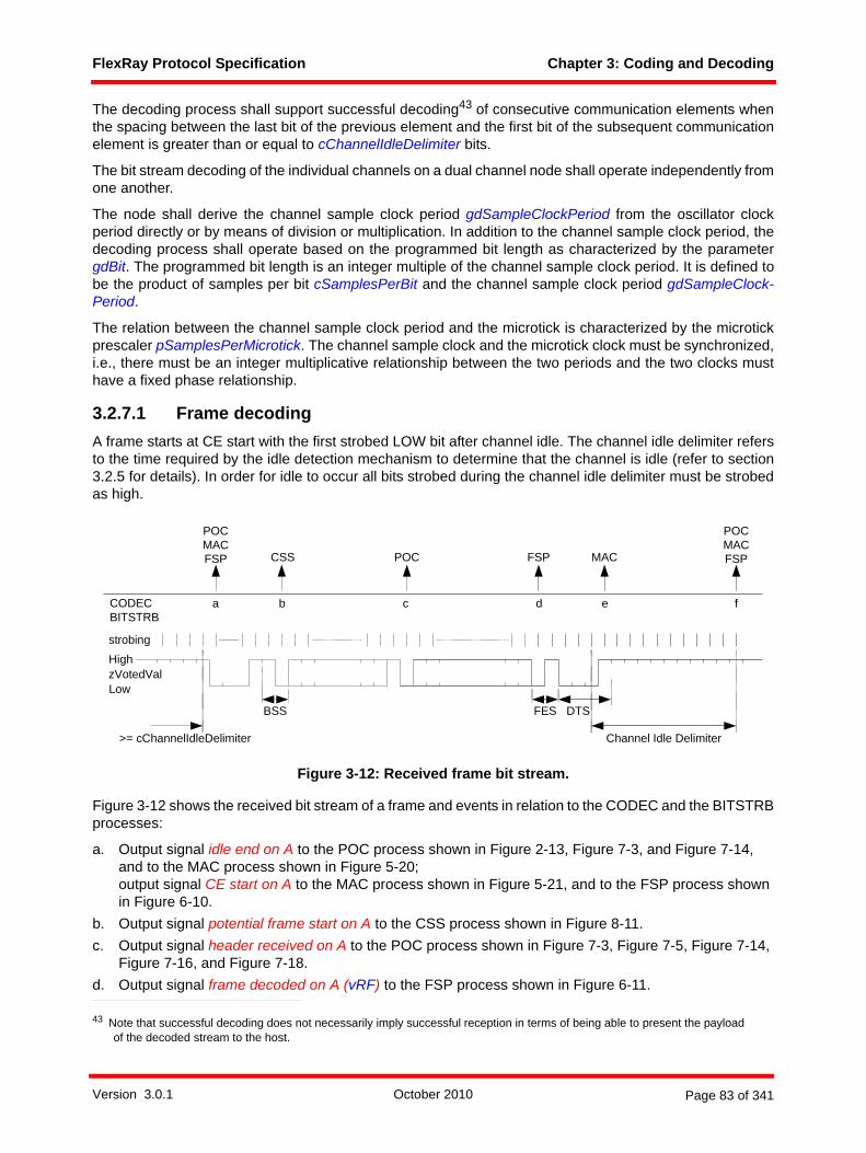
FlexRay Protocol Specification Chapter 3: Coding and Decoding
The decoding process shall support successful decoding43 of consecutive communication elements whenthe spacing between the last bit of the previous element and the first bit of the subsequent communicationelement is greater than or equal to cChannelIdleDelimiter bits.
The bit stream decoding of the individual channels on a dual channel node shall operate independently fromone another.
The node shall derive the channel sample clock period gdSampleClockPeriod from the oscillator clockperiod directly or by means of division or multiplication. In addition to the channel sample clock period, thedecoding process shall operate based on the programmed bit length as characterized by the parametergdBit. The programmed bit length is an integer multiple of the channel sample clock period. It is defined tobe the product of samples per bit cSamplesPerBit and the channel sample clock period gdSampleClock-Period.
The relation between the channel sample clock period and the microtick is characterized by the microtickprescaler pSamplesPerMicrotick. The channel sample clock and the microtick clock must be synchronized,i.e., there must be an integer multiplicative relationship between the two periods and the two clocks musthave a fixed phase relationship.
3.2.7.1 Frame decodingA frame starts at CE start with the first strobed LOW bit after channel idle. The channel idle delimiter refersto the time required by the idle detection mechanism to determine that the channel is idle (refer to section3.2.5 for details). In order for idle to occur all bits strobed during the channel idle delimiter must be strobedas high.
Figure 3-12: Received frame bit stream.
Figure 3-12 shows the received bit stream of a frame and events in relation to the CODEC and the BITSTRBprocesses:
a. Output signal idle end on A to the POC process shown in Figure 2-13, Figure 7-3, and Figure 7-14, and to the MAC process shown in Figure 5-20; output signal CE start on A to the MAC process shown in Figure 5-21, and to the FSP process shown in Figure 6-10.
b. Output signal potential frame start on A to the CSS process shown in Figure 8-11.c. Output signal header received on A to the POC process shown in Figure 7-3, Figure 7-5, Figure 7-14,
Figure 7-16, and Figure 7-18.d. Output signal frame decoded on A (vRF) to the FSP process shown in Figure 6-11.
43 Note that successful decoding does not necessarily imply successful reception in terms of being able to present the payload of the decoded stream to the host.
a
strobing
Channel Idle Delimiter
High
LowzVotedVal
b c d
DTS
>= cChannelIdleDelimiter
CODECBITSTRB
f
FESBSS
FSPCSS POC
POCMACFSP
POCMACFSP
e
MAC
Version 3.0.1 October 2010 Page 83 of 341
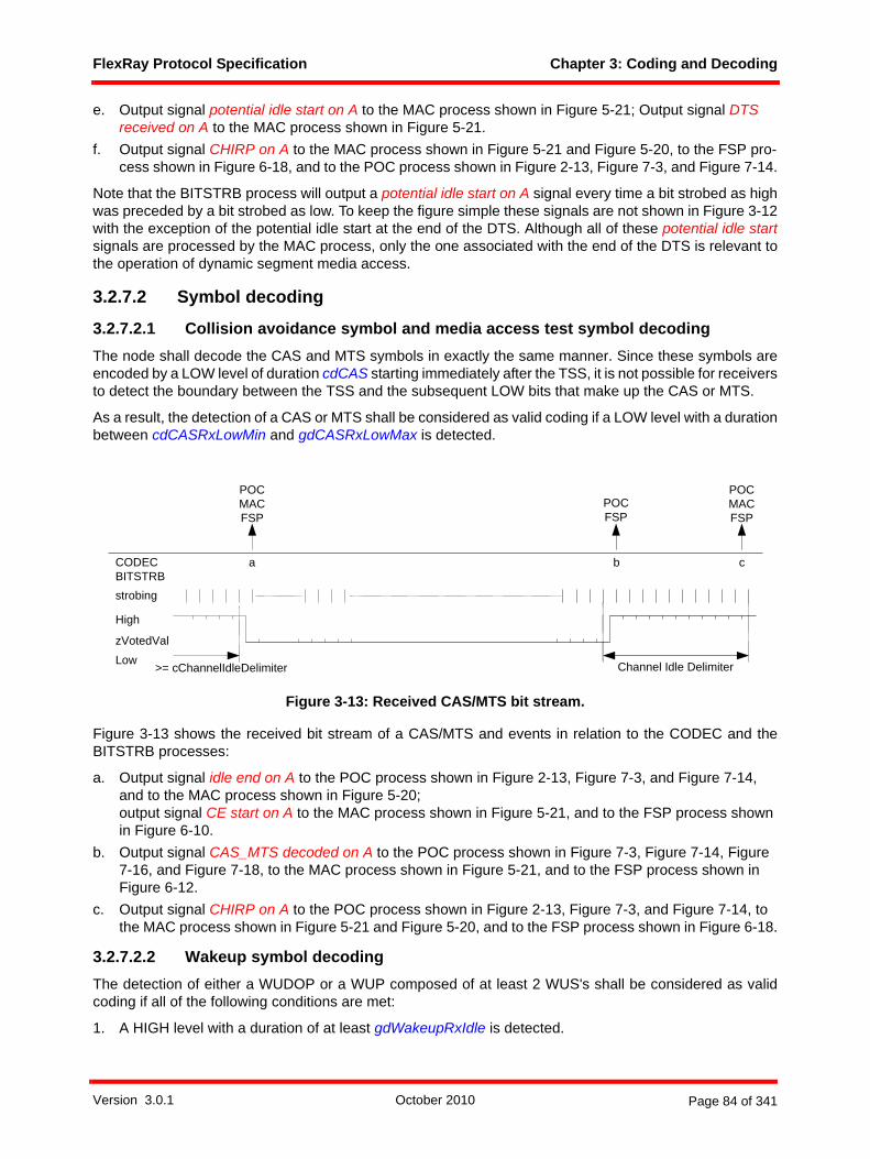
FlexRay Protocol Specification Chapter 3: Coding and Decoding
e. Output signal potential idle start on A to the MAC process shown in Figure 5-21; Output signal DTS received on A to the MAC process shown in Figure 5-21.
f. Output signal CHIRP on A to the MAC process shown in Figure 5-21 and Figure 5-20, to the FSP pro-cess shown in Figure 6-18, and to the POC process shown in Figure 2-13, Figure 7-3, and Figure 7-14.
Note that the BITSTRB process will output a potential idle start on A signal every time a bit strobed as highwas preceded by a bit strobed as low. To keep the figure simple these signals are not shown in Figure 3-12with the exception of the potential idle start at the end of the DTS. Although all of these potential idle startsignals are processed by the MAC process, only the one associated with the end of the DTS is relevant tothe operation of dynamic segment media access.
3.2.7.2 Symbol decoding
3.2.7.2.1 Collision avoidance symbol and media access test symbol decodingThe node shall decode the CAS and MTS symbols in exactly the same manner. Since these symbols areencoded by a LOW level of duration cdCAS starting immediately after the TSS, it is not possible for receiversto detect the boundary between the TSS and the subsequent LOW bits that make up the CAS or MTS.
As a result, the detection of a CAS or MTS shall be considered as valid coding if a LOW level with a durationbetween cdCASRxLowMin and gdCASRxLowMax is detected.
Figure 3-13: Received CAS/MTS bit stream.
Figure 3-13 shows the received bit stream of a CAS/MTS and events in relation to the CODEC and theBITSTRB processes:
a. Output signal idle end on A to the POC process shown in Figure 2-13, Figure 7-3, and Figure 7-14, and to the MAC process shown in Figure 5-20; output signal CE start on A to the MAC process shown in Figure 5-21, and to the FSP process shown in Figure 6-10.
b. Output signal CAS_MTS decoded on A to the POC process shown in Figure 7-3, Figure 7-14, Figure 7-16, and Figure 7-18, to the MAC process shown in Figure 5-21, and to the FSP process shown in Figure 6-12.
c. Output signal CHIRP on A to the POC process shown in Figure 2-13, Figure 7-3, and Figure 7-14, to the MAC process shown in Figure 5-21 and Figure 5-20, and to the FSP process shown in Figure 6-18.
3.2.7.2.2 Wakeup symbol decodingThe detection of either a WUDOP or a WUP composed of at least 2 WUS's shall be considered as validcoding if all of the following conditions are met:
1. A HIGH level with a duration of at least gdWakeupRxIdle is detected.
strobing
High
LowzVotedVal
Channel Idle Delimiter>= cChannelIdleDelimiter
a bCODECBITSTRB
POCMACFSP
c
POCMACFSP
POCFSP
Version 3.0.1 October 2010 Page 84 of 341

FlexRay Protocol Specification Chapter 3: Coding and Decoding
2. This is followed by a duration of at least gdWakeupRxLow at the LOW level. After this duration a win-dow timer is started, even if the LOW level is still present. The timer will expire after gdWakeupRxWin-dow.
3. This is followed by a duration of at least gdWakeupRxIdle at the HIGH level.4. This is followed by a duration of at least gdWakeupRxLow at the LOW level.5. This is followed by a duration of at least gdWakeupRxIdle at the HIGH level.6. The last three phases of HIGH, LOW and HIGH are received before the window timer that was started
during the first LOW phase has expired.
The bit stream received by node 3 in Figure 3-6 shows the reception of a WUP and the related eventrelevant to the WUPDEC process of node 3:
d. Output signal wakeup decoded on A to the POC process shown in Figure 7-3 and Figure 7-5, and to the FSP process shown in Figure 6-8.
3.2.7.3 Decoding errorExiting one of the decoding macros CAS_MTS_DECODING, FSS_BSS_DECODING, HEADER_DE-CODING, PAYLOAD_DECODING, or TRAILER_DECODING (shown in Figure 3-26) with an exit conditionof decoding error shall abort and restart the decoding again. Prior to doing so, the FSP is informed aboutthe decoding error.
When a decoding error is detected the node shall treat the first wrong bit as the last bit of the current commu-nication element, i.e. it shall terminate communication element decoding and shall wait for successfulchannel idle detection.
The following condition shall not lead to a decoding error:• One or three HIGH bits (instead of exactly two HIGH bits) are strobed after the TSS.
In the FSS-BSS sequence, it is possible that, due to the quantization error of one sample period from thereceiver's point of view, an incoming HIGH level of 2 gdBit length (FSS + first bit of the BSS) may be inter-preted as
1. (2 * cSamplesPerBit - 1) or2. (2 * cSamplesPerBit) or 3. (2 * cSamplesPerBit + 1)
samples long.
This could also arise as a systematic effect due to slow/fast clocks of the node and the analog-to-digitalconversion of the signal.
Figure 3-14 shows an example FSS-BSS decoding with only (2 * cSamplesPerBit - 1) samples of HIGH.Under all conditions at least one leading HIGH bit between the TSS and the first data byte is accuratelydecoded.
In addition to the effects of quantization, the presence of asymmetry could also result in additional reductionor lengthening of the actual duration of the HIGH period of the FSS-BSS sequence. Any amount ofasymmetry that is accommodated by the decoding algorithm would still result in the strobing of between oneand three bits at HIGH. Refer to [EPLAN10] for additional details.
Version 3.0.1 October 2010 Page 85 of 341
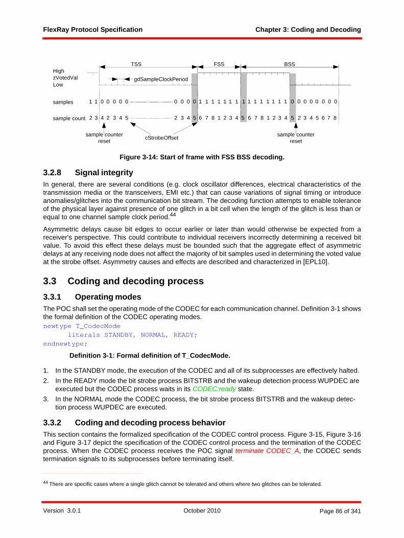
FlexRay Protocol Specification Chapter 3: Coding and Decoding
Figure 3-14: Start of frame with FSS BSS decoding.
3.2.8 Signal integrityIn general, there are several conditions (e.g. clock oscillator differences, electrical characteristics of thetransmission media or the transceivers, EMI etc.) that can cause variations of signal timing or introduceanomalies/glitches into the communication bit stream. The decoding function attempts to enable toleranceof the physical layer against presence of one glitch in a bit cell when the length of the glitch is less than orequal to one channel sample clock period.44
Asymmetric delays cause bit edges to occur earlier or later than would otherwise be expected from areceiver's perspective. This could contribute to individual receivers incorrectly determining a received bitvalue. To avoid this effect these delays must be bounded such that the aggregate effect of asymmetricdelays at any receiving node does not affect the majority of bit samples used in determining the voted valueat the strobe offset. Asymmetry causes and effects are described and characterized in [EPL10].
3.3 Coding and decoding process3.3.1 Operating modesThe POC shall set the operating mode of the CODEC for each communication channel. Definition 3-1 showsthe formal definition of the CODEC operating modes.newtype T_CodecMode
literals STANDBY, NORMAL, READY;endnewtype;
Definition 3-1: Formal definition of T_CodecMode.
1. In the STANDBY mode, the execution of the CODEC and all of its subprocesses are effectively halted. 2. In the READY mode the bit strobe process BITSTRB and the wakeup detection process WUPDEC are
executed but the CODEC process waits in its CODEC:ready state.3. In the NORMAL mode the CODEC process, the bit strobe process BITSTRB and the wakeup detec-
tion process WUPDEC are executed.
3.3.2 Coding and decoding process behaviorThis section contains the formalized specification of the CODEC control process. Figure 3-15, Figure 3-16and Figure 3-17 depict the specification of the CODEC control process and the termination of the CODECprocess. When the CODEC process receives the POC signal terminate CODEC_A, the CODEC sendstermination signals to its subprocesses before terminating itself.
44 There are specific cases where a single glitch cannot be tolerated and others where two glitches can be tolerated.
High
LowzVotedVal
TSS FSS
samples 1 0 0 0 0 0 0 0 0 0 1 1 1 1
gdSampleClockPeriod
sample count
1
3 4 2 3 4 5 2 3 4 5 6 7 8 1 2
1
2
1 1 1
3 4 5
sample counter reset
1 1 1
BSS
1 1 1 1 0 0 0 0 0 0 0 0
6 7 8 1 2 3 4 5 2 3 4 5 6 7 8
cStrobeOffset sample counter reset
Version 3.0.1 October 2010 Page 86 of 341
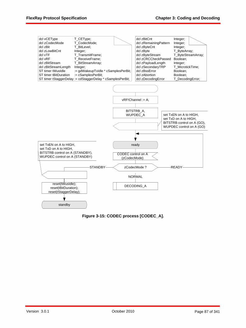
FlexRay Protocol Specification Chapter 3: Coding and Decoding
Figure 3-15: CODEC process [CODEC_A].
CODEC control on A(zCodecMode)
zCodecMode ?
ready
NORMAL
dcl vCEType T_CEType;dcl zCodecMode T_CodecMode;dcl zBit T_BitLevel;dcl zLowBitCnt Integer;dcl vTF T_TransmitFrame;dcl vRF T_ReceiveFrame;dcl zBitStream T_BitStreamArray;dcl zBitStreamLength Integer;ST timer tWusIdle := gdWakeupTxIdle * cSamplesPerBit;ST timer tBitDuration := cSamplesPerBit;ST timer tStaggerDelay := cdStaggerDelay * cSamplesPerBit;
dcl zBitCnt Integer;dcl zRemainingPattern Integer;dcl zByteCnt Integer;dcl zByte T_ByteArray;dcl zByteStream T_ByteStreamArray;dcl zCRCCheckPassed Boolean;dcl zPayloadLength Integer;dcl zSecondaryTRP T_MicrotickTime;dcl zBssError Boolean;dcl zAbortion Boolean;dcl zDecodingError T_DecodingError;
set TxEN on A to HIGH,set TxD on A to HIGH,BITSTRB control on A (GO),WUPDEC control on A (GO)
DECODING_A
STANDBY
standby
set TxEN on A to HIGH,set TxD on A to HIGH,BITSTRB control on A (STANDBY),WUPDEC control on A (STANDBY)
vRF!Channel := A;
READY
BITSTRB_A,WUPDEC_A
reset(tWusIdle);reset(tBitDuration);
reset(tStaggerDelay);
Version 3.0.1 October 2010 Page 87 of 341
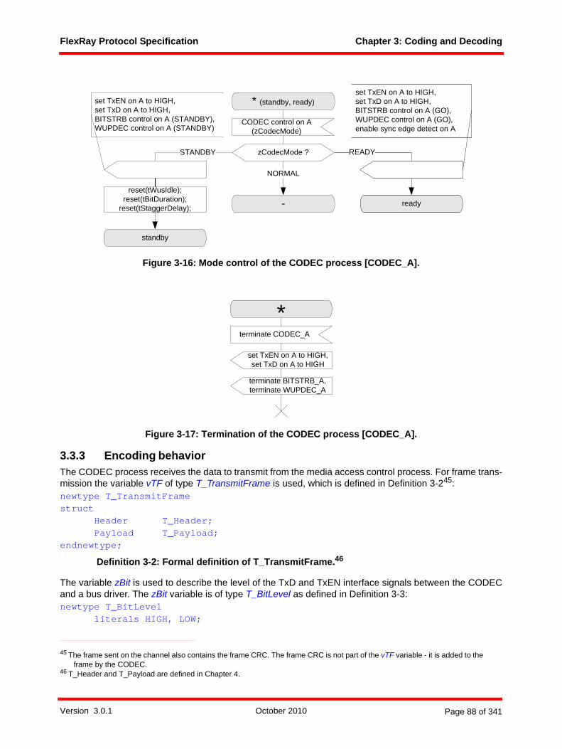
FlexRay Protocol Specification Chapter 3: Coding and Decoding
Figure 3-16: Mode control of the CODEC process [CODEC_A].
Figure 3-17: Termination of the CODEC process [CODEC_A].
3.3.3 Encoding behaviorThe CODEC process receives the data to transmit from the media access control process. For frame trans-mission the variable vTF of type T_TransmitFrame is used, which is defined in Definition 3-245:newtype T_TransmitFramestruct
Header T_Header;Payload T_Payload;
endnewtype;
Definition 3-2: Formal definition of T_TransmitFrame.46
The variable zBit is used to describe the level of the TxD and TxEN interface signals between the CODECand a bus driver. The zBit variable is of type T_BitLevel as defined in Definition 3-3:newtype T_BitLevel
literals HIGH, LOW;
45 The frame sent on the channel also contains the frame CRC. The frame CRC is not part of the vTF variable - it is added to the frame by the CODEC.
46 T_Header and T_Payload are defined in Chapter 4.
STANDBY
set TxEN on A to HIGH,set TxD on A to HIGH,BITSTRB control on A (STANDBY),WUPDEC control on A (STANDBY)
standby
ready
CODEC control on A(zCodecMode)
* (standby, ready)
zCodecMode ? READY
-
NORMAL
set TxEN on A to HIGH,set TxD on A to HIGH,BITSTRB control on A (GO),WUPDEC control on A (GO),enable sync edge detect on A
reset(tWusIdle);reset(tBitDuration);
reset(tStaggerDelay);
terminate CODEC_A
terminate BITSTRB_A,terminate WUPDEC_A
set TxEN on A to HIGH,set TxD on A to HIGH
*
Version 3.0.1 October 2010 Page 88 of 341
FlexRay Protocol Specification Chapter 3: Coding and Decoding
endnewtype;
Definition 3-3: Formal definition of T_BitLevel.
The CODEC process provides the assembled bit stream via the TxD signal to the BD (with the SDL signalsset TxD on A to HIGH and set TxD on A to LOW) and controls the BD via the TxEN signal (the SDL signalsset TxEN on A to HIGH and set TxEN on A to LOW). The transmitting node shall set TxD to HIGH in thecase of a '1' bit and shall set TxD to LOW in the case of a '0' bit.
Figure 3-18 shows a high level view of the mechanisms used for encoding. After the reception of a transmitframe on A or transmit symbol on A signal the CODEC process follows one of four distinct paths dependingon the type of communication element that is to be encoded. Each of these paths is described in a separatemacro. Before any of the macros are executed, however, the CODEC process sets the TxEN output to LOWand puts the BITSTRB and WUPDEC processes into STANDBY mode.
If the CE to be encoded is a frame, the FRAME_ENCODING macro is executed (see Figure 3-19). Thismacro calls the prepbitstream function, which takes the inbound frame vTF from the MAC process,prepares the bit stream zBitStream of type T_BitStreamArray for transmission, and calculates the bit streamlength zBitStreamLength. The prepbitstream function shall break the frame data down into individualbytes, prepend a TSS, add an FSS at the end of the TSS, create a series of extended byte sequences byadding a BSS at the beginning of each byte of frame data, calculate the frame CRC bytes and create theextended byte sequences for the CRC, and assemble a continuous bit stream out of the extended bytesequences. Once the bit stream is prepared, the macro steps bit by bit through the stream and presents itto the bus. Following this, the FRAME_ENCODING macro calls the TRANSMIT_FES macro and, if theframe is sent in the dynamic segment, the TRANSMIT_DTS macro. Once all of these are complete, themacro sends a control signal to the BITSTRB process that restarts bit strobing in the BLIND mode.
If the CE to be encoded is a CAS/MTS, the CAS_MTS_ENCODING macro is executed (see Figure 3-24).This macro simply sets the TxD output to LOW and leaves it at this state for an appropriate period of time(the duration of TSS plus the duration of the CAS). Once the necessary duration has passed (as indicatedby the WAIT function described in Figure 3-22) the TxEN output is deactivated and the BITSTRB processis restarted in the BLIND mode. Following a delay of cdStaggerDelay bits (see section 3.2.1.2.1), the TxDoutput is also deactivated.
If the CE to be encoded is a Wakeup Pattern, the WUP_ENCODING macro is executed (see Figure 3-23).This macro loops through pWakeupPattern iterations, each one creating a WUS as described in section3.2.1.2.2. As the low phase of each WUS is completed, the WUP_ENCODING macro provides thenecessary staggering of the TxD and TxEN outputs, and commands the BITSTRB process to the BLINDmode to begin the process of allowing the detection of wakeup symbol collisions. If a collision is detected(by detecting cdWakeupMaxCollision consecutive LOW bits) the WUP_ENCODING macro is aborted,signaling a wakeup collision. If no collision is detected, the macro will loop until all WUS's have beengenerated and then exit.
If the CE to be encoded is a WUDOP, the WUDOP_ENCODING macro is executed (see Figure 3-25). Thismacro transmits a sequence of LOW-HIGH-LOW-HIGH-LOW phases followed by a brief HIGH phase.Following the last HIGH phase the TxEN output is deactivated and the BITSTRB process is restarted in theBLIND mode.
newtype T_BitStreamArrayArray (Integer, T_BitLevel);
endnewtype;
Definition 3-4: Formal definition of T_BitStreamArray.
Version 3.0.1 October 2010 Page 89 of 341

FlexRay Protocol Specification Chapter 3: Coding and Decoding
Figure 3-18: Encoding mechanism [CODEC_A].
Immediately after instantiating of the CODEC process, the encoder sends the signal set TxEN on A to HIGHto disable the BD's transmitter.newtype T_CEType
literals STATFRAME, DYNFRAME, CAS_MTS, WUP, WUDOP;endnewtype;
Definition 3-5: Formal definition of T_CEType.
* (standby, ready)
transmit symbol on A (vCEType)
CAS_MTS
WUP_ENCODING_A
STATFRAME,DYNFRAME vCEType ?
WUP
wait for CE start
transmit frame on A (vCEType, vTF)
CAS_MTS_ENCODING_AFRAME_ENCODING_A
decoding halted on A,WUPDEC control on A (STANDBY),BITSTRB control on A (STANDBY),set TxEN on A to LOW
WUDOP_ENCODING_A
WUDOP
decoding started on A, WUPDEC control on A (GO)
Version 3.0.1 October 2010 Page 90 of 341

FlexRay Protocol Specification Chapter 3: Coding and Decoding
3.3.4 Encoding macros
Figure 3-19: Encoding macro FRAME_ENCODING_A [CODEC_A].
set(tBitDuration);
wait for end of bit
LOW
=zBitStreamLength
zBitCnt?
zBitCnt := zBitCnt+ 1;
else
set TxD on A to LOW set TxD on A to HIGH
zBitStream(zBitCnt) ? HIGH
prepbitstream(vTF, zBitStream, zBitStreamLength);
zBitCnt := 0;
stop transmission on A
TRANSMIT_DTS_A
TRANSMIT_FES_A
DYNFRAME
vCEType ?
done
frame transmitted on A
else
transmissionaborted
set TxEN on A to HIGH,BITSTRB control on A (BLIND)
FRAME_ENCODING_A
tBitDuration
WAIT_A(1)
set TxD on A to HIGH
Version 3.0.1 October 2010 Page 91 of 341

FlexRay Protocol Specification Chapter 3: Coding and Decoding
Figure 3-20: Encoding macro TRANSMIT_FES_A [CODEC_A].
TRANSMIT_FES_A
set(tBitDuration);
tBitDuration
wait for end of FES bit 2
false
done
set TxD on A to HIGH
set(tBitDuration);zAbortion := false;
wait for end of FES bit 1
set TxD on A to LOW
tBitDuration
transmission aborted
true
stop transmission on A
zAbortion := true;
stop transmission on A
zAbortion := true;zAbortion ?
Version 3.0.1 October 2010 Page 92 of 341

FlexRay Protocol Specification Chapter 3: Coding and Decoding
Figure 3-21: Encoding macro TRANSMIT_DTS_A [CODEC_A].
Figure 3-22: Procedure WAIT_A [CODEC_A].
TRANSMIT_DTS_A
set(tBitDuration);
tBitDuration
wait for end of first DTS bit
DTS start on A
stop transmission on A
wait for DTS end
set TxD on A to LOW
stop transmission on A
zWait ?
wait for bit duration
set(tBitDuration);
else
tBitDuration
zWait := zWait - 1;
<= 0
WAIT_A(zWait)fpar zWait;
Version 3.0.1 October 2010 Page 93 of 341
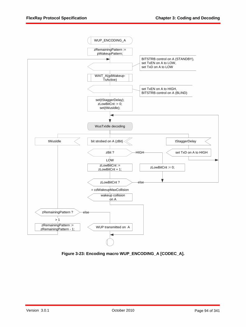
FlexRay Protocol Specification Chapter 3: Coding and Decoding
Figure 3-23: Encoding macro WUP_ENCODING_A [CODEC_A].
zRemainingPattern := pWakeupPattern;
> 1
zRemainingPattern ? else
zRemainingPattern :=zRemainingPattern - 1; WUP transmitted on A
set TxD on A to HIGH
set TxEN on A to HIGH,BITSTRB control on A (BLIND)
set(tStaggerDelay);zLowBitCnt := 0;
set(tWusIdle);
tStaggerDelay
WUP_ENCODING_A
BITSTRB control on A (STANDBY),set TxEN on A to LOW,set TxD on A to LOW
zBit ?
WusTxIdle decoding
elsezLowBitCnt ?
zLowBitCnt :=zLowBitCnt + 1;
wakeup collisionon A
= cdWakeupMaxCollision
LOW
HIGH
zLowBitCnt := 0;
tWusIdle
WAIT_A(gdWakeup-TxActive)
bit strobed on A (zBit)
Version 3.0.1 October 2010 Page 94 of 341
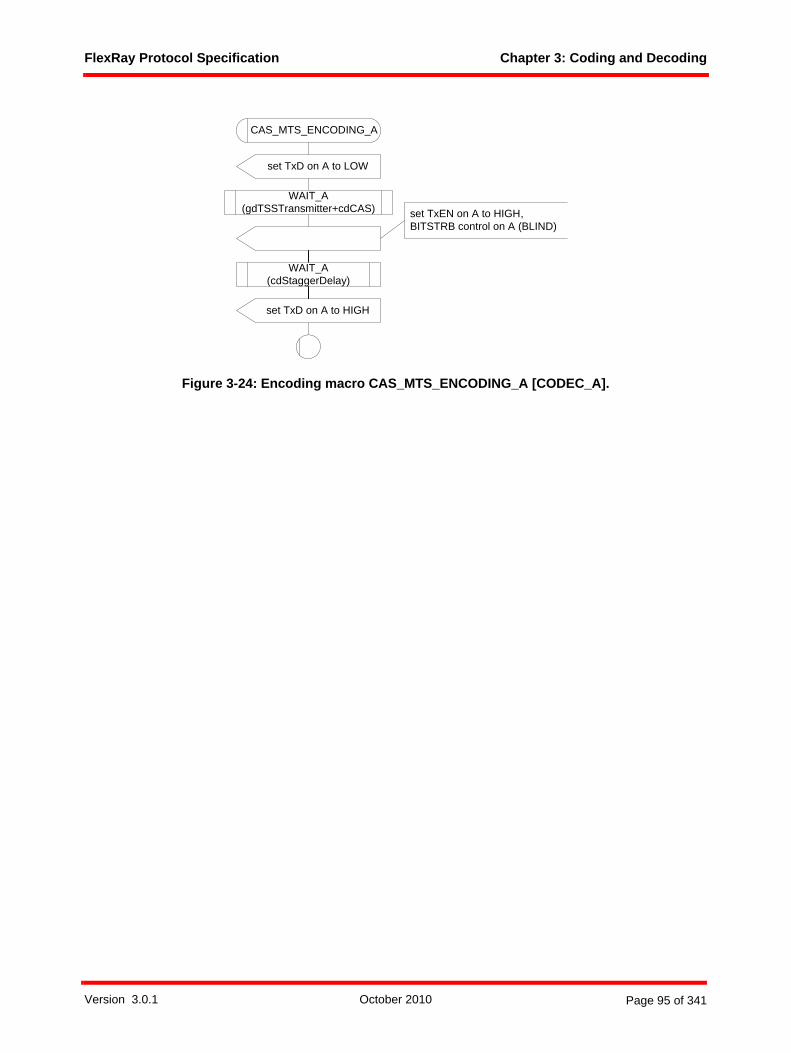
FlexRay Protocol Specification Chapter 3: Coding and Decoding
Figure 3-24: Encoding macro CAS_MTS_ENCODING_A [CODEC_A].
set TxEN on A to HIGH,BITSTRB control on A (BLIND)
set TxD on A to HIGH
CAS_MTS_ENCODING_A
set TxD on A to LOW
WAIT_A(gdTSSTransmitter+cdCAS)
WAIT_A (cdStaggerDelay)
Version 3.0.1 October 2010 Page 95 of 341

FlexRay Protocol Specification Chapter 3: Coding and Decoding
Figure 3-25: Encoding macro WUDOP_ENCODING_A [CODEC_A].
3.3.5 Decoding behaviorA receiving node shall decode the received bit stream provided by the BITSTRB process according to theCODEC process.
set TxD on A to HIGH
set TxEN on A to HIGH,BITSTRB control on A (BLIND)
WUDOP_ENCODING_A
set TxD on A to LOW
WAIT_A(gdWakeup-TxActive)
WAIT_A(1)
set TxD on A to HIGH
WAIT_A(gdWakeup-TxActive)
set TxD on A to LOW
WAIT_A(gdWakeup-TxActive)
set TxD on A to HIGH
WAIT_A(gdWakeup-TxActive)
set TxD on A to LOW
WAIT_A(gdWakeup-TxActive)
Version 3.0.1 October 2010 Page 96 of 341
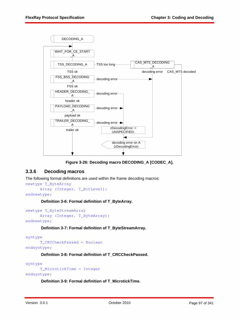
FlexRay Protocol Specification Chapter 3: Coding and Decoding
Figure 3-26: Decoding macro DECODING_A [CODEC_A].
3.3.6 Decoding macrosThe following formal definitions are used within the frame decoding macros:newtype T_ByteArray
Array (Integer, T_BitLevel);endnewtype;
Definition 3-6: Formal definition of T_ByteArray.
newtype T_ByteStreamArrayArray (Integer, T_ByteArray);
endnewtype;
Definition 3-7: Formal definition of T_ByteStreamArray.
syntype T_CRCCheckPassed = Boolean
endsyntype;
Definition 3-8: Formal definition of T_CRCCheckPassed.
syntypeT_MicrotickTime = Integer
endsyntype;
Definition 3-9: Formal definition of T_MicrotickTime.
WAIT_FOR_CE_START_A
CAS_MTS_DECODING_ATSS_DECODING_A TSS too long
FSS_BSS_DECODING_A
TSS ok
HEADER_DECODING_A
PAYLOAD_DECODING_A
FSS ok
header ok
payload okTRAILER_DECODING_
Atrailer ok
CAS_MTS decoded
decoding error
decoding error
decoding error
decoding error
decoding error on A (zDecodingError)
decoding error
DECODING_A
zDecodingError := UNSPECIFIED;
Version 3.0.1 October 2010 Page 97 of 341

FlexRay Protocol Specification Chapter 3: Coding and Decoding
newtype T_ReceiveFramestruct
PrimaryTRP T_MicrotickTime;Channel T_Channel;Header T_Header;Payload T_Payload;
endnewtype;
Definition 3-10: Formal definition of T_ReceiveFrame.
newtype T_DecodingErrorliterals CAS_MTS_TOO_SHORT, FSS_TOO_LONG, UNSPECIFIED;
endnewtype;
Definition 3-11: Formal definition of T_DecodingError.
Figure 3-27: Decoding macro WAIT_FOR_CE_START_A [CODEC_A].
Figure 3-28: Decoding macro TSS_DECODING_A [CODEC_A].
wait for CE start
WAIT_FOR_CE_START_A
CE start on A
TSS_DECODING_A
bit strobed on A (zBit)
zBit ?
TSS decoding
LOW
zBitCnt:= 1;
zBitCnt := zBitCnt + 1;
zBitCnt ?
HIGH
> gdTSSTransmitter + 2
TSS okTSS too long
else
Version 3.0.1 October 2010 Page 98 of 341
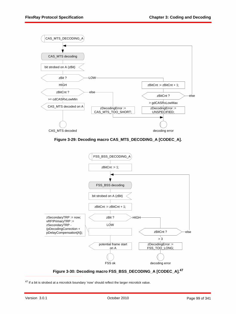
FlexRay Protocol Specification Chapter 3: Coding and Decoding
Figure 3-29: Decoding macro CAS_MTS_DECODING_A [CODEC_A].
Figure 3-30: Decoding macro FSS_BSS_DECODING_A [CODEC_A].47
47 If a bit is strobed at a microtick boundary ’now’ should reflect the larger microtick value.
CAS_MTS_DECODING_A
bit strobed on A (zBit)
zBit ?
CAS_MTS decoding
elsezBitCnt ?
>= cdCASRxLowMin
CAS_MTS decoded on A> gdCASRxLowMax
CAS_MTS decoded decoding error
zBitCnt := zBitCnt + 1;HIGH
LOW
elsezBitCnt ?
zDecodingError := CAS_MTS_TOO_SHORT;
zDecodingError := UNSPECIFIED;
FSS_BSS_DECODING_A
bit strobed on A (zBit)
FSS_BSS decoding
zBitCnt := zBitCnt + 1;
zBit ?
potential frame starton A
FSS ok
HIGH
zBitCnt ?
> 3
decoding error
else
LOW
zBitCnt := 1;
zSecondaryTRP := now;vRF!PrimaryTRP := zSecondaryTRP - (pDecodingCorrection + pDelayCompensation[A]);
zDecodingError := FSS_TOO_LONG;
Version 3.0.1 October 2010 Page 99 of 341
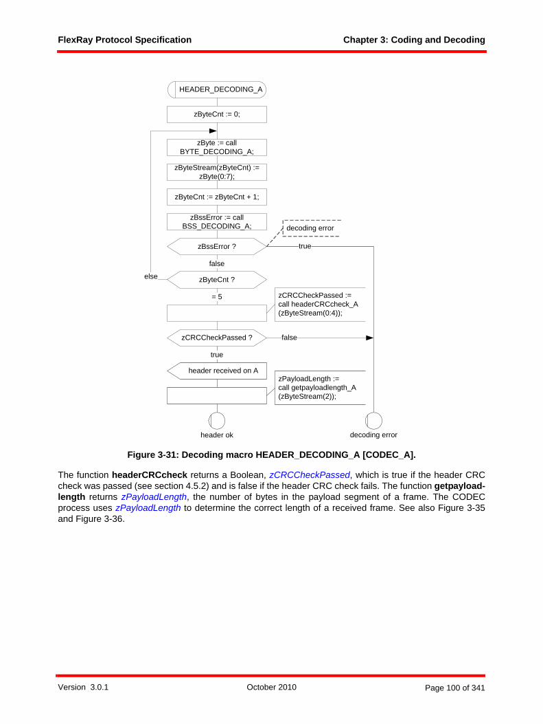
FlexRay Protocol Specification Chapter 3: Coding and Decoding
Figure 3-31: Decoding macro HEADER_DECODING_A [CODEC_A].
The function headerCRCcheck returns a Boolean, zCRCCheckPassed, which is true if the header CRCcheck was passed (see section 4.5.2) and is false if the header CRC check fails. The function getpayload-length returns zPayloadLength, the number of bytes in the payload segment of a frame. The CODECprocess uses zPayloadLength to determine the correct length of a received frame. See also Figure 3-35and Figure 3-36.
HEADER_DECODING_A
zByteCnt := 0;
false
zByteCnt ?
= 5
else
zCRCCheckPassed ?
true
false
header received on A
decoding errorheader ok
zCRCCheckPassed := call headerCRCcheck_A(zByteStream(0:4));
zPayloadLength := call getpayloadlength_A(zByteStream(2));
truezBssError ?
decoding error
zByteStream(zByteCnt) := zByte(0:7);
zByteCnt := zByteCnt + 1;
zByte := call BYTE_DECODING_A;
zBssError := call BSS_DECODING_A;
Version 3.0.1 October 2010 Page 100 of 341
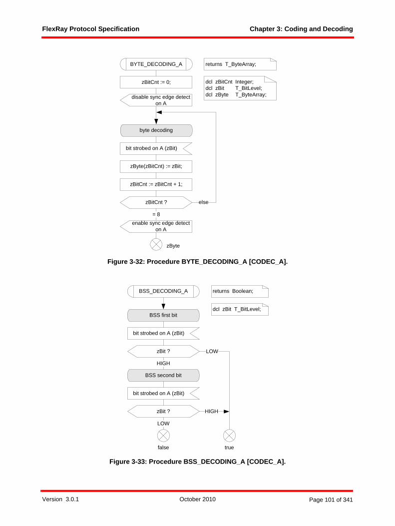
FlexRay Protocol Specification Chapter 3: Coding and Decoding
Figure 3-32: Procedure BYTE_DECODING_A [CODEC_A].
Figure 3-33: Procedure BSS_DECODING_A [CODEC_A].
bit strobed on A (zBit)
byte decoding
zBitCnt := 0;
zBitCnt := zBitCnt + 1;
zBitCnt ? else
zByte(zBitCnt) := zBit;
= 8
BYTE_DECODING_A
zByte
returns T_ByteArray;
dcl zBitCnt Integer; dcl zBit T_BitLevel;dcl zByte T_ByteArray;
enable sync edge detect on A
disable sync edge detect on A
bit strobed on A (zBit)
zBit ?
BSS first bit
HIGH
LOW
bit strobed on A (zBit)
zBit ?
BSS second bit
LOW
HIGH
BSS_DECODING_A returns Boolean;
dcl zBit T_BitLevel;
truefalse
Version 3.0.1 October 2010 Page 101 of 341
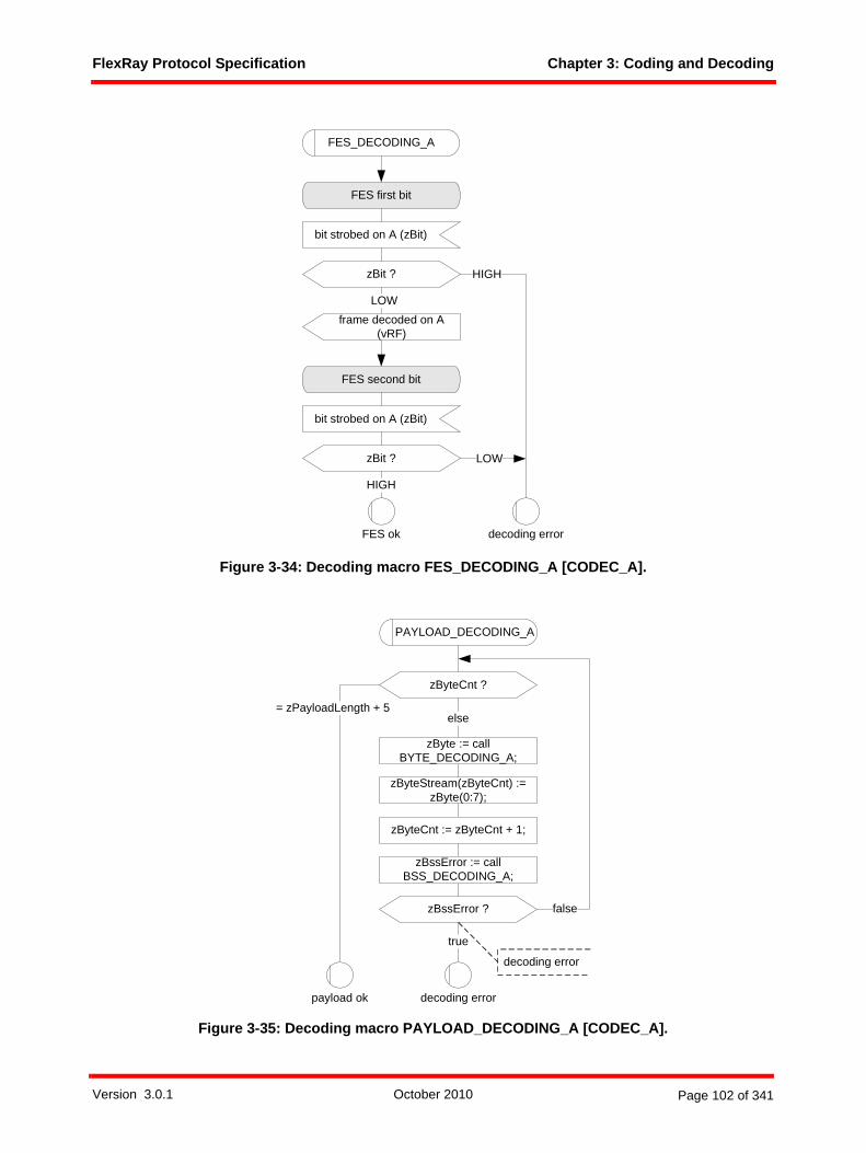
FlexRay Protocol Specification Chapter 3: Coding and Decoding
Figure 3-34: Decoding macro FES_DECODING_A [CODEC_A].
Figure 3-35: Decoding macro PAYLOAD_DECODING_A [CODEC_A].
FES_DECODING_A
bit strobed on A (zBit)
zBit ?
FES first bit
LOW
bit strobed on A (zBit)
zBit ?
FES second bit
HIGH
FES ok
HIGH
LOW
decoding error
frame decoded on A(vRF)
PAYLOAD_DECODING_A
true
false
zByteCnt ?
= zPayloadLength + 5else
decoding errorpayload ok
zBssError ?
decoding error
zByteStream(zByteCnt) := zByte(0:7);
zByteCnt := zByteCnt + 1;
zByte := call BYTE_DECODING_A;
zBssError := call BSS_DECODING_A;
Version 3.0.1 October 2010 Page 102 of 341

FlexRay Protocol Specification Chapter 3: Coding and Decoding
Figure 3-36: Decoding macro TRAILER_DECODING_A [CODEC_A].
The function frameCRCcheck returns a Boolean, zCRCCheckPassed, which is true if the frame CRC checkwas passed (see section 4.5.3) and is false if the frame CRC check fails. This function is channel specificdue to the channel specific initialization vectors of the CRC calculation (see section 4.5.3 for details).
The function getRF used in Figure 3-36 extracts decoded header and payload data from zByteStream andreturns it via the structure variable vRF.
TRAILER_DECODING_A
true
false
zByteCnt ?
= zPayloadLength + 7
else
zCRCCheckPassed ?
true
false
FES_DECODING_A decoding error
FES ok
vRF := call getRF_A (zByteStream (0:zByteCnt));
decoding error
trailer ok
zCRCCheckPassed := call frameCRCcheck_A (zByteStream (0:zByteCnt));
zBssError ?
decoding error
zByteStream(zByteCnt) := zByte(0:7);
zByteCnt := zByteCnt + 1;
zByteStream(zByteCnt) := zByte(0:7);
zByte := call BYTE_DECODING_A;
zByte := call BYTE_DECODING_A;
zBssError := call BSS_DECODING_A;
DTS_DECODING_A
Version 3.0.1 October 2010 Page 103 of 341

FlexRay Protocol Specification Chapter 3: Coding and Decoding
Figure 3-37: Decoding macro DTS_DECODING_A [CODEC_A].
3.4 Bit strobing process3.4.1 Operating modesThe receiving node shall strobe the received data from the BD according to the bit strobing processBITSTRB. Definition 3-12 shows the formal definition of the BITSTRB operating modes: newtype T_StrbMode
literals STANDBY, GO, BLIND;endnewtype;
Definition 3-12: Formal definition of T_StrbMode.
The bit strobing process BITSTRB has the following three operating modes:
1. In the STANDBY mode bit strobing is effectively halted.2. In the GO mode the bit strobing process shall be executed.3. In the BLIND mode the bit strobing process is paused for a configurable interval. After expiration of this
interval the mode is switched automatically to GO.
With the instantiation of the CODEC process the bit strobing process BITSTRB is set in the mode GO andat any transition of the CODEC process to CODEC:standby the bit strobing process BITSTRB is set toSTANDBY.
DTS_DECODING_A
DTS first bit
bit strobed on A (zBit)
zBit ?
wait for DTS reception end
bit strobed on A (zBit)
zBit ?
DTS received on A
LOW
HIGH
LOW
HIGH
Version 3.0.1 October 2010 Page 104 of 341
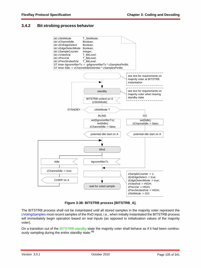
FlexRay Protocol Specification Chapter 3: Coding and Decoding
3.4.2 Bit strobing process behavior
Figure 3-38: BITSTRB process [BITSTRB_A].
The BITSTRB process shall not be instantiated until all stored samples in the majority voter represent thecVotingSamples most recent samples of the RxD input, i.e., when initially instantiated the BITSTRB processwill immediately begin operation based on real inputs (as opposed to initialization values of the majorityvoter).
On a transition out of the BITSTRB:standby state the majority voter shall behave as if it had been continu-ously sampling during the entire standby state.48
BITSTRB control on A(zStrbMode)
zStrbMode ?STANDBY
standby
zSampleCounter := 1;zEnEdgeDetect := true;zEdgeDetectMode := true;zVotedVal := HIGH;zPrevVal := HIGH;zPrevStrobedVal := HIGH;zStrbMode := GO;
blind
tIgnoreAfterTx
wait for voted sample
set(tIgnoreAfterTx);set(tIdle);
zChannelIdle := false;
GOBLIND
dcl zStrbMode T_StrbMode;dcl zChannelIdle Boolean;dcl zEnEdgeDetect Boolean;dcl zEdgeDetectMode Boolean;dcl zSampleCounter Integer;dcl zVotedVal T_BitLevel;dcl zPrevVal T_BitLevel;dcl zPrevStrobedVal T_BitLevel;ST timer tIgnoreAfterTx := gdIgnoreAfterTx * cSamplesPerBit;ST timer tIdle := cChannelIdleDelimiter * cSamplesPerBit;
potential idle start on A
set(tIdle);zChannelIdle := false;
potential idle start on A
see text for requirements on majority voter when leaving standby state
see text for requirements on majority voter at BITSTRB instantiation
tIdle
zChannelIdle := true;
CHIRP on A
Version 3.0.1 October 2010 Page 105 of 341

FlexRay Protocol Specification Chapter 3: Coding and Decoding
Figure 3-39: Wait for voted sample [BITSTRB_A].
48 Note that this is not a requirement that an implementation must actually sample when BITSTRB is in the BITSTRB:standby state - an implementation that restarted sampling several samples before the transition out of standby would also be acceptable.
wait for voted sample
enable sync edge detect on A
zEdgeDetectMode := true; zEdgeDetectMode := false;zEnEdgeDetect := false;
false
true
disable sync edge detect on A
zSampleCounter := 2;zEnEdgeDetect := false;
zSampleCounter := zSampleCounter + 1;
zSampleCounter ?
> cSamplesPerBit
zSampleCounter := 1;
zSampleCounter ?
bit strobed on A (zVotedVal)
= cStrobeOffset
else
zPrevStrobedVal := zVotedVal;
else
CHIRP on A
zChannelIdle := true;
zVotedVal ?
zChannelIdle ?
truefalse
LOW
zPrevStrobedVal ?
potential idle start on A
LOW
HIGH
HIGH
(zEnEdgeDetect = true)and (zPrevVal = HIGH)and (zVotedVal = LOW) ?
zEnEdgeDetect := true;
zEdgeDetectMode ?
falsetrue
tIdlevoted RxD on A(zVotedVal)
CE start on A,idle end on A
zChannelIdle := false;
set(tIdle);
zPrevVal := zVotedVal;
Version 3.0.1 October 2010 Page 106 of 341

FlexRay Protocol Specification Chapter 3: Coding and Decoding
Figure 3-40: BITSTRB process control and process termination [BITSTRB_A].
3.5 Wakeup pattern decoding process3.5.1 Operating modesThe WUPDEC process is responsible for detecting wakeups present on the bus. Such wakeups could eithercome from WUPs that are transmitted as part of the initial FlexRay wakeup process or from WUDOPs thatare transmitted as part of the wakeup during operation procedure.
The wakeup pattern decoding process WUPDEC distinguishes between two modes. Definition 3-13 showsthe formal definition of the WUPDEC operating modes:newtype T_WupDecMode
literals STANDBY, GO;endnewtype;
Definition 3-13: Formal definition of T_WupDecMode.
1. In the STANDBY mode, the wakeup pattern decoding process (WUPDEC) is effectively halted.2. In the GO mode, the node shall decode wakeup patterns.
BITSTRB control on A(zStrbMode)
zStrbMode ?
-
else
standby
STANDBY
terminate BITSTRB_A
idle end on A
reset(tIgnoreAfterTx);reset(tIdle);
(standby)* *
Version 3.0.1 October 2010 Page 107 of 341

FlexRay Protocol Specification Chapter 3: Coding and Decoding
3.5.2 Wakeup pattern decoding process behavior
Figure 3-41: Control of the wakeup pattern decoding process and its termination [WUPDEC_A].
standby
WUPDEC control on A(zWupDecMode)
dcl zBit T_BitLevel;dcl zLastLevel T_BitLevel;dcl zWupDecMode T_WupDecMode;
ST timer tWUPWindow := gdWakeupRxWindow * cSamplesPerBit;ST timer tWUPLow := gdWakeupRxLow * cSamplesPerBit;ST timer tWUPHigh := gdWakeupRxIdle * cSamplesPerBit;
zWupDecMode ?
GO
standby
else
(standby)
zWupDecMode ?
STANDBY
else
standbybus level evaluation -
*
*
HIGH
zLastLevel ?
bit strobed on A (zLastLevel)
set(tWUPHigh);
LOW
wait for idle
reset(tWUPLow);reset(tWUPHigh);
reset(tWUPWindow);
terminateWUPDEC_A
WUPDEC control on A(zWupDecMode)
Version 3.0.1 October 2010 Page 108 of 341

FlexRay Protocol Specification Chapter 3: Coding and Decoding
Figure 3-42: Control of the wakeup timer [WUPDEC_A].
set(tWUPLow);reset(tWUPHigh);
reset(tWUPLow);set(tWUPHigh);
-
wait for idle, low1 decoding, idle1 decoding, low2 decoding, idle2 decoding
zBit ?
HIGH LOW
bit strobed on A (zBit)
true
zBit != zLastLevel ?
zLastLevel := zBit;
false
Version 3.0.1 October 2010 Page 109 of 341
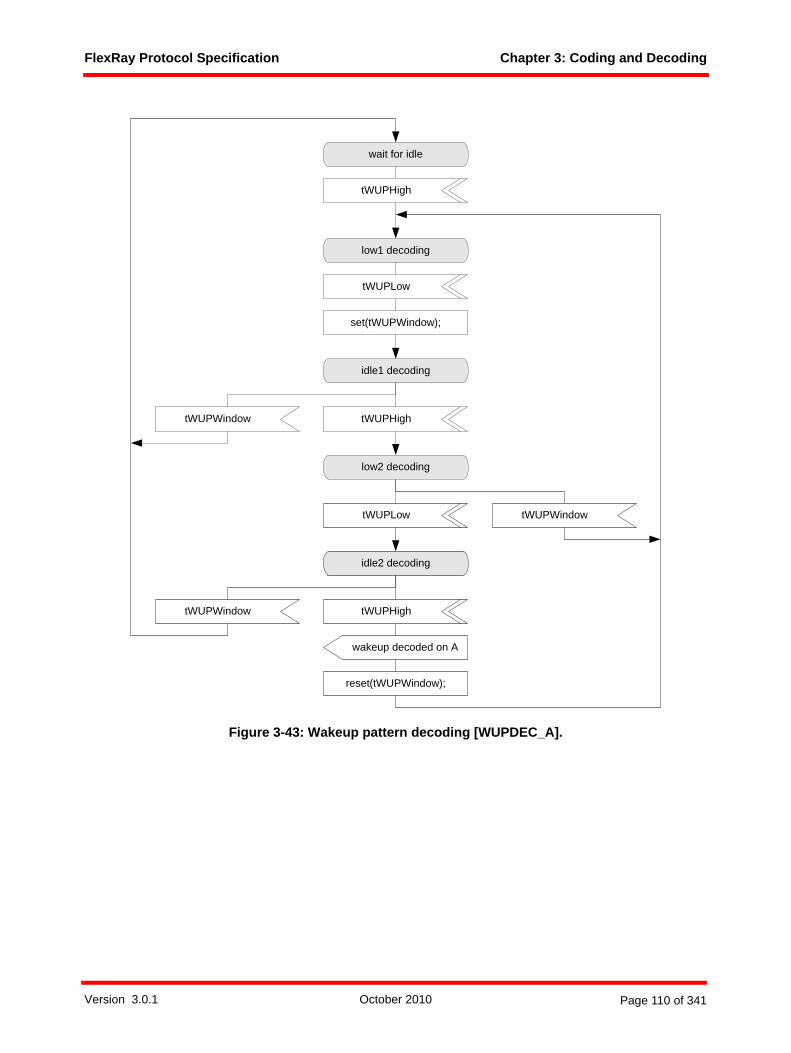
FlexRay Protocol Specification Chapter 3: Coding and Decoding
Figure 3-43: Wakeup pattern decoding [WUPDEC_A].
low1 decoding
set(tWUPWindow);
wakeup decoded on A
reset(tWUPWindow);
idle1 decoding
wait for idle
low2 decoding
idle2 decoding
tWUPHigh
tWUPHigh
tWUPLow
tWUPLow
tWUPHightWUPWindow
tWUPWindow
tWUPWindow
Version 3.0.1 October 2010 Page 110 of 341

FlexRay Protocol Specification Chapter 4: Frame Format
Chapter 4Frame Format
4.1 OverviewAn overview of the FlexRay frame format is given in Figure 4-1. The frame consists of three segments.These are the header segment, the payload segment, and the trailer segment.
Figure 4-1: FlexRay frame format.
The node shall transmit the frame on the network such that the header segment appears first, followed bythe payload segment, and then followed by the trailer segment, which is transmitted last. Within theindividual segments the node shall transmit the fields in left to right order as depicted in Figure 4-1, (in theheader segment, for example, the reserved bit is transmitted first and the cycle count field is transmittedlast).
4.2 FlexRay header segment (5 bytes)The FlexRay header segment consists of 5 bytes. These bytes contain the reserved bit, the payloadpreamble indicator, the null frame indicator, the sync frame indicator, the startup frame indicator, the frameID, the payload length, the header CRC, and the cycle count.
4.2.1 Reserved bit (1 bit)The reserved bit is reserved for future protocol use. It shall not be used by the application.
• A transmitting node shall set the reserved bit to logical '0'.• A receiving node shall ignore the reserved bit.49
CRC CRC
24 bits
Data nFrame ID
7 bits 0 ... 254 bytes
Cyclecount CRC
FlexRay Frame 5 + (0 ... 254) + 3 bytes
Payloadlength
11 bits 6 bits
Sync
fram
e in
dica
tor
11 bits
HeaderCRC
Nul
l fra
me
indi
cato
r
Header Segment Payload Segment Trailer Segment
Header CRCCovered Area
Payl
oad
prea
mbl
e in
dica
tor
Res
erve
d bi
t
11111
Star
tup
fram
e in
dica
tor
Data 0 Data 1 Data 2
Version 3.0.1 October 2010 Page 111 of 341

FlexRay Protocol Specification Chapter 4: Frame Format
syntype T_Reserved = Integerconstants 0 : 1
endsyntype;
Definition 4-1: Formal definition of T_Reserved.
4.2.2 Payload preamble indicator (1 bit)The payload preamble indicator indicates whether or not an optional vector is contained within the payloadsegment of the frame transmitted:
• If the frame is transmitted in the static segment the payload preamble indicator indicates thepresence of a network management vector at the beginning of the payload.
• If the frame is transmitted in the dynamic segment the payload preamble indicator indicates thepresence of a message ID at the beginning of the payload.
If the payload preamble indicator is set to zero then the payload segment of the frame does not contain anetwork management vector or a message ID, respectively.
If the payload preamble indicator is set to one then the payload segment of the frame contains a networkmanagement vector if it is transmitted in the static segment or a message ID if it is transmitted in the dynamicsegment.syntype T_PPIndicator = Integer
constants 0 : 1endsyntype;
Definition 4-2: Formal definition of T_PPIndicator.
4.2.3 Null frame indicator (1 bit)The null frame indicator indicates whether or not the frame is a null frame, i.e. a frame that contains nouseable data in the payload segment of the frame.50 The conditions under which a transmitting node maysend a null frame are detailed in Chapter 5. Nodes that receive a null frame may still use some informationrelated to the frame.51
• If the null frame indicator is set to zero then the payload segment contains no valid data. All bytes inthe payload segment are set to zero, and the payload preamble indicator is set to zero.
• If the null frame indicator is set to one then the payload segment contains data.syntype T_NFIndicator = Integer
constants 0 : 1endsyntype;
Definition 4-3: Formal definition of T_NFIndicator.
4.2.4 Sync frame indicator (1 bit)The sync frame indicator indicates whether or not the frame is a sync frame, i.e. a frame that is utilized forsystem wide synchronization of communication.52
49 The receiving node uses the value of the reserved bit for the Frame CRC checking process, but otherwise ignores its value (i.e., the receiver shall accept either a 1 or a 0 in this field).
50 The null frame indicator indicates only whether payload data was available to the communication controller at the time the frame was sent. A null frame indicator set to zero informs the receiving node(s) that data in the payload segment must not be used. If the bit is set to one data is present in the payload segment from the transmitting communication controller's perspective. The receiving node may still have to do additional checks to decide whether the data is actually valid from an application perspective.
51 For example, the clock synchronization algorithm will use the arrival time of null frames with the Sync frame indicator set to one (provided all other criteria for that frame's acceptance are met).
52 Sync frames are only sent in the static segment. Please refer to the rules to configure sync frames.
Version 3.0.1 October 2010 Page 112 of 341

FlexRay Protocol Specification Chapter 4: Frame Format
• If the sync frame indicator is set to zero then no receiving node shall consider the frame for synchro-nization or synchronization related tasks.
• If the sync frame indicator is set to one then all receiving nodes shall utilize the frame for synchroni-zation if it meets other acceptance criteria (see below).
The clock synchronization mechanism (described in Chapter 8) makes use of the sync frame indicator.There are several conditions that result in the sync frame indicator being set to one and subsequentlyutilized by the clock synchronization mechanism. Details of how the node shall set the sync frame indicatorare specified in Chapter 5 and section 8.8.syntype T_SyFIndicator = Integer
constants 0 : 1endsyntype;
Definition 4-4: Formal definition of T_SyFIndicator.
4.2.5 Startup frame indicator (1 bit)The startup frame indicator indicates whether or not a frame is a startup frame. Startup frames serve aspecial role in the startup mechanism. Only coldstart nodes are allowed to transmit startup frames.
• If the startup frame indicator is set to zero then the frame is not a startup frame.• If the startup frame indicator is set to one then the frame is a startup frame.
The startup frame indicator shall only be set to one in the sync frames of coldstart nodes. Therefore, a framewith the startup frame indicator set to one shall also have the sync frame indicator set to one. As a result,all valid startup frames are also sync frames.
The startup (described in Chapter 7) and clock synchronization (described in Chapter 8) mechanisms utilizethe startup frame indicator. In both cases, the condition that the startup frame indicator is set to one is onlyone of several conditions necessary for the frame to be used by the mechanisms. Details regarding how thenode sets the startup frame indicator are specified in Chapter 5.53 syntype T_SuFIndicator = Integer
constants 0 : 1endsyntype;
Definition 4-5: Formal definition of T_SuFIndicator.
4.2.6 Frame ID (11 bits)The frame ID defines the slot in which the frame should be transmitted. A frame ID is used no more thanonce on each channel in a communication cycle. Each frame that may be transmitted in a cluster has aframe ID assigned to it.
The frame ID ranges from 1 to 204754. The frame ID 0 is an invalid frame ID55.
The node shall transmit the frame ID such that the most significant bit of the frame ID is transmitted first withthe remaining bits of the frame ID being transmitted in decreasing order of significance.syntype T_FrameID = Integer
constants 0 : 204756
53 The configuration of exactly three nodes in a cluster as coldstart nodes avoids the formation of cliques during startup for several fault scenarios. It is also possible to configure more than three nodes as coldstart nodes but the clique avoidance mechanism will not work in this case.
54 In binary: from (000 0000 0001)2 to (111 1111 1111)255 The frame ID of a transmitted frame is determined by the value of vSlotCounter(Ch) at the time of transmission (see Chapter
5). In the absence of faults, vSlotCounter(Ch) can never be zero when a slot is available for transmission. Received frames with frame ID zero will always be identified as erroneous because a slot ID mismatch is a certainty due to the fact that there is no slot with ID zero.
56 Frame IDs range from 1 to 2047. The zero is used to mark invalid frames, empty slots, etc.
Version 3.0.1 October 2010 Page 113 of 341

FlexRay Protocol Specification Chapter 4: Frame Format
endsyntype;
Definition 4-6: Formal definition of T_FrameID.
4.2.7 Payload length (7 bits)The payload length field is used to indicate the size of the payload segment. The payload segment size isencoded in this field by setting it to the number of payload data bytes divided by two (e.g., a frame thatcontains a payload segment consisting of 72 bytes would be sent with the payload length set to 36).57
The payload length ranges from 0 to cPayloadLengthMax58, which corresponds to a payload segmentcontaining 2 * cPayloadLengthMax bytes.
The payload length shall be fixed and identical for all frames sent in the static segment of a communicationcycle. For these frames the payload length field shall be transmitted with the payload length set to gPayload-LengthStatic.
The payload length may be different for different frames in the dynamic segment of a communication cycle.In addition, the payload length of a specific dynamic segment frame may vary from cycle to cycle. Finally,the payload lengths of a specific dynamic segment frame may be different on each configured channel.
The node shall transmit the payload length such that the most significant bit of the payload length is trans-mitted first with the remaining bits of the payload length being transmitted in decreasing order of signifi-cance.syntype T_Length = Integer
constants 0 : cPayloadLengthMaxendsyntype;
Definition 4-7: Formal definition of T_Length.
4.2.8 Header CRC (11 bits)The header CRC contains a cyclic redundancy check code (CRC) that is computed over the sync frameindicator, the startup frame indicator, the frame ID, and the payload length. The CC shall not calculate theheader CRC for a transmitted frame. The header CRC of transmitted frames is computed offline andprovided to the CC by means of configuration (i.e., it is not computed by the transmitting CC).59 The CCshall calculate the header CRC of a received frame in order to check that the CRC is correct.
The CRC is computed in the same manner for all configured channels. The CRC polynomial60 shall be
The initialization vector of the register used to generate the header CRC shall be 0x01A.
With respect to the computation of the header CRC, the sync frame indicator shall be shifted in first, followedby the startup frame indicator, followed by the most significant bit of the frame ID, followed by subsequentbits of the frame ID, followed by the most significant bit of the payload length, and followed by subsequentbits of the payload length.
57 The payload length field does not include the number of bytes within the header and the trailer segments of the FlexRay frame.
58 The electrical physical layer puts a restriction on the usable payload such that the overall transmission duration is limited (see [EPL10]. It may restrict the payload length at 2.5 and 5 Mbit/s. For details please refer to sections B.4.40 and B.4.41.
59 For a given frame in the static segment the values of the header fields covered by the CRC do not change during the operation of the cluster in the absence of faults. Implicitly, the CRC does not need to change either. Offline calculation of the CRC makes it unlikely that a fault-induced change to the covered header fields will also result in a frame with a valid header CRC (since the CRC is not recalculated based on the modified header fields).
60 This 11 bit CRC polynomial generates a (31,20) BCH code that has a minimum Hamming distance of 6. The codeword consists of the data to be protected and the CRC. In this application, this CRC protects exactly 20 bits of data (1 sync frame indicator bit + 1 startup frame indicator bit + 11 frame ID bits + 7 payload length bits = 20 bits). This polynomial was obtained from [Wad01] and its properties were verified using the techniques described in [Koo02].
x11 x9 x8 x7 x2 1+ + + + + x 1+( ) x5 x3 1+ +( ) x5 x4 x3 x 1+ + + +( )⋅ ⋅=
Version 3.0.1 October 2010 Page 114 of 341

FlexRay Protocol Specification Chapter 4: Frame Format
The node shall transmit the header CRC such that the most significant bit of the header CRC is transmittedfirst with the remaining bits of the header CRC being transmitted in decreasing order of significance.
A detailed description of how to generate and verify the header CRC is given in section 4.5.2.syntype T_HeaderCRC = Integer
constants 0 : 2047 endsyntype;
Definition 4-8: Formal definition of T_HeaderCRC.
4.2.9 Cycle count (6 bits)The cycle count indicates the transmitting node's view of the value of the cycle counter vCycleCounter atthe time of frame transmission (see section 5.3.2.2 and section 5.3.3.2).
The node shall transmit the cycle count such that the most significant bit of the cycle count is transmittedfirst with the remaining bits of the cycle count being transmitted in decreasing order of significance.syntype T_CycleCounter = Integer
constants 0 : 63 endsyntype;
Definition 4-9: Formal definition of T_CycleCounter.
4.2.10 Formal header definitionThe formal definitions of the fields in the previous sections and the header segment structure depicted inFigure 4-1 yield the following formal definition for the header segment:newtype T_Headerstruct
Reserved T_Reserved;PPIndicator T_PPIndicator;NFIndicator T_NFIndicator;SyFIndicator T_SyFIndicator;SuFIndicator T_SuFIndicator;FrameID T_FrameID;Length T_Length;HeaderCRC T_HeaderCRC;CycleCount T_CycleCounter;
endnewtype;
Definition 4-10: Formal definition of T_Header.
4.3 FlexRay payload segment (0 - 254 bytes)The FlexRay payload segment contains 0 to 25461 bytes (0 to 127 two-byte words) of data. Because thepayload length contains the number of two-byte words, the payload segment contains an even number ofbytes. The bytes of the payload segment are identified numerically, starting at 0 for the first byte after theheader segment and increasing by one with each subsequent byte. The individual bytes are referred to as"Data 0", "Data 1", "Data 2", etc., with "Data 0" being the first byte of the payload segment, "Data 1" beingthe second byte, etc.
The frame CRC described in section 4.5.3 has a Hamming distance of six for payload lengths up to andincluding 248 bytes. For payload lengths greater than 248 bytes the CRC has a Hamming distance of four.
61 The electrical physical layer puts a restriction on the usable payload such that the overall transmission duration is limited (see [EPL10]). It may restrict the payload length at 2.5 and 5 Mbit/s. For details please refer to sections B.4.40 and B.4.41.
Version 3.0.1 October 2010 Page 115 of 341
FlexRay Protocol Specification Chapter 4: Frame Format
For frames transmitted in the dynamic segment the first two bytes of the payload segment may optionallybe used as a message ID field, allowing receiving nodes to filter or steer data based on the contents of thisfield. The payload preamble indicator in the frame header indicates whether the payload segment containsthe message ID.
For frames transmitted in the static segment the first 0 to 12 bytes of the payload segment may be used asa network management vector. The payload preamble indicator in the frame header indicates whether thepayload segment contains the network management vector62. The length of the network managementvector gNetworkManagementVectorLength is configured during the POC:config state and cannot bechanged in any other state. gNetworkManagementVectorLength can be configured between 0 and 12bytes, inclusive.
Starting with payload "Data 0" the node shall transmit the bytes of the payload segment such that the mostsignificant bit of the byte is transmitted first with the remaining bits of the byte being transmitted indecreasing order of significance.63
The product specific host interface specification determines the mapping between the position of bytes inthe buffer and the position of the bytes in the payload segment of the frame.newtype T_Payload
Array(T_Length, Integer)endnewtype;
Definition 4-11: Formal definition of T_Payload.
4.3.1 NMVectorA number of bytes in the payload segment of the FlexRay frame format in a frame transmitted in the staticsegment can be used as Network Management Vector (NMVector).
• The length of the NMVector is configured during POC:config by the parameter gNetworkManage-mentVectorLength. All nodes in a cluster must be configured with the same value for this parameter.
• The NMVector may only be used in frames transmitted in the static segment.• At the transmitting node the NMVector is written by the host as application data. The communica-
tion controller has no knowledge about the NMVector and no mechanism inside the communicationcontroller is based on the NMVector except the ORing function described in section 9.3.3.4.
• The optional presence of NMVector is indicated in the frame header by the payload preambleindicator.
• The bits in a byte of the NMVector shall be transmitted such that the most significant bit of a byte istransmitted first followed by the remaining bits being transmitted in decreasing order of significance.
• The least significant byte of the NMVector is transmitted first followed by the remaining bytes inincreasing order of significance.64
62 Frames that contain network management data are not restricted to contain only network management data - the other bytes in the payload segment may be used to convey additional, non-Network Management data.
63 If a message ID exists, the most significant byte of the message ID is transmitted first followed by the least significant byte of the message ID. If no message ID exists the transmission starts with the first payload data byte (Data 0) followed by the remaining payload data bytes.
64 This allows lower bits to remain at defined positions if the length of the NMVector changes.
Version 3.0.1 October 2010 Page 116 of 341
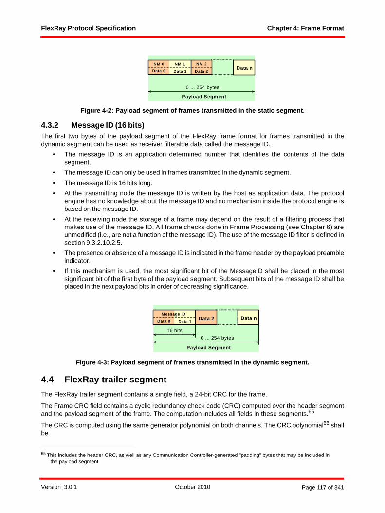
FlexRay Protocol Specification Chapter 4: Frame Format
Figure 4-2: Payload segment of frames transmitted in the static segment.
4.3.2 Message ID (16 bits) The first two bytes of the payload segment of the FlexRay frame format for frames transmitted in thedynamic segment can be used as receiver filterable data called the message ID.
• The message ID is an application determined number that identifies the contents of the datasegment.
• The message ID can only be used in frames transmitted in the dynamic segment.• The message ID is 16 bits long. • At the transmitting node the message ID is written by the host as application data. The protocol
engine has no knowledge about the message ID and no mechanism inside the protocol engine isbased on the message ID.
• At the receiving node the storage of a frame may depend on the result of a filtering process thatmakes use of the message ID. All frame checks done in Frame Processing (see Chapter 6) areunmodified (i.e., are not a function of the message ID). The use of the message ID filter is defined insection 9.3.2.10.2.5.
• The presence or absence of a message ID is indicated in the frame header by the payload preambleindicator.
• If this mechanism is used, the most significant bit of the MessageID shall be placed in the mostsignificant bit of the first byte of the payload segment. Subsequent bits of the message ID shall beplaced in the next payload bits in order of decreasing significance.
Figure 4-3: Payload segment of frames transmitted in the dynamic segment.
4.4 FlexRay trailer segmentThe FlexRay trailer segment contains a single field, a 24-bit CRC for the frame.
The Frame CRC field contains a cyclic redundancy check code (CRC) computed over the header segmentand the payload segment of the frame. The computation includes all fields in these segments.65
The CRC is computed using the same generator polynomial on both channels. The CRC polynomial66 shallbe
65 This includes the header CRC, as well as any Communication Controller-generated "padding" bytes that may be included in the payload segment.
Data n
0 ... 254 bytes
Payload Segment
Data 0 Data 1 Data 2
NM 2NM 1NM 0
Data n
0 ... 254 bytes16 bits
Message ID
Payload Segment
Data 0 Data 1Data 2
Version 3.0.1 October 2010 Page 117 of 341

FlexRay Protocol Specification Chapter 4: Frame Format
The node shall use a different initialization vector depending on which channel the frame should be trans-mitted67:
• The node shall use the initialization vector 0xFEDCBA for frames sent on channel A.• The node shall use the initialization vector 0xABCDEF for frames sent on channel B.
With respect to the computation of the frame CRC, the frame fields shall be fed into the CRC generator innetwork order starting with the reserved bit, and ending with the least significant bit of the last byte of thepayload segment.
The frame CRC shall be transmitted such that the most significant bit of the frame CRC is transmitted firstwith the remaining bits of the frame CRC being transmitted in decreasing order of significance.
A detailed description of how to generate or verify the Frame CRC is given in section 4.5.3.syntype T_FrameCRC = Integer
constants 0x000000 : 0xFFFFFFendsyntype;
Definition 4-12: Formal definition of T_FrameCRC.
4.5 CRC calculation detailsThe behavior of the CODEC while processing a received frame depends on whether or not the receivedheader and frame CRCs are verified to match the values locally calculated using the actual frame data (seeFigure 3-31 and Figure 3-36). The CODEC also appends the CRC in the trailer segment of a transmittedframe (see section 3.2.1.1.6). The algorithm executed to calculate the CRC is the same in all cases exceptfor the initial values of several algorithm parameters (see below).
4.5.1 CRC calculation algorithmInitialize the CRC shift register with the appropriate initialization value. As long as bits (vNextBit) from theheader or payload segment of the frame are available the while-loop is executed. The number of bitsavailable in the payload segment is derived from the payload length field. The bits68 of the header andpayload segments are fed into the CRC register by using the variable vNextBit, bit by bit, in network order,e.g., for the FlexRay frame CRC calculation the first bit used as vNextBit is the reserved bit field, and thelast bit used is the least significant bit of the last byte of the payload segment.
The following pseudo code summarizes the CRC calculation algorithm:
vCrcReg(vCrcSize - 1 : 0) = vCrcInit; // Initialize the CRC registerwhile(vNextBit)
66 This 24-bit CRC polynomial generates a code that has a minimum Hamming distance of 6 for codewords up to 2048 bits in length and a minimum Hamming distance of 4 for codewords up to 4094 bits in length. The codeword consists of all frame data and the CRC. This corresponds to H=6 protection for FlexRay frames with payload lengths up to 248 bytes and H=4 protection for longer payload lengths. This polynomial was obtained from[Cas93] , and its properties were verified using the techniques described in[Koo02] .
67 Different initialization vectors are defined to prevent a node from communicating if it has crossed channels, connection of a single channel node to the wrong channel, or shorted channels (both controller channels connected to the same physical channel).
68 Transmitting nodes use the bit sequence that will be fed into the coding algorithm (see Chapter 3), including any controller generated padding bits. Receivers use the decoded sequence as received from the decoding algorithm (i.e., after the removal of any coding sequences (e.g. Byte Start Sequences, Frame Start Sequences, etc.)).
x24 x22 x20 x19 x18 x16 x14 x13 x11 x10 x8 x7 x6 x3 x 1+ + + + + + + + + + + + + + +
x 1+( )2 x11 x9 x8 x7 x5 x3 x2 x 1+ + + + + + + +( ) x11 x9 x8 x7 x6 x3 1+ + + + + +( )⋅ ⋅=
Version 3.0.1 October 2010 Page 118 of 341

FlexRay Protocol Specification Chapter 4: Frame Format
// determine if the CRC polynomial has to be applied by taking // the exclusive OR of the most significant bit of the CRC register // and the next bit to be fed into the register
vCrcNext = vNextBit EXOR vCrcReg(vCrcSize - 1);
// Shift the CRC register left by one bit
vCrcReg (vCrcSize - 1 : 1) = vCrcReg(vCrcSize - 2 : 0);vCrcReg(0) = 0;
// Apply the CRC polynomial if necessary
if vCrcNext vCrcReg(vCrcSize - 1 : 0) =
vCrcReg(vCrcSize - 1 : 0) EXOR vCrcPolynomial;end; // end if
end; // end while loop
4.5.2 Header CRC calculationAmong its other uses, the header CRC field of a FlexRay frame is intended to provide protection againstimproper modification of the sync frame indicator or startup frame indicator fields by a faulty communicationcontroller (CC). The CC that is responsible for transmitting a particular frame shall not compute the headerCRC field for that frame. Rather, the CC shall be configured with the appropriate header CRC for a givenframe by the host69.
When a CC receives a frame it shall perform the header CRC computations based on the header fieldvalues received and check the computed value against the header CRC value received in the frame. Theframes from each channel are processed independently. The algorithm described in section 4.5.1 is usedto calculate the header CRC. The parameters for the algorithm are defined as follows:
FlexRay header CRC calculation algorithm parameters:
vCrcSize = cHCrcSize; // (= 11) size of the register is 11 bitsvCrcInit = cHCrcInit; // (= 0x1A) initialization vector of header
// CRC for both channels vCrcPolynomial = cHCrcPolynomial; // (= 0x385) hexadecimal representation of
// the header CRC polynomial
The results of the calculation (vCrcReg) are compared to the header CRC value in the frame. If thecalculated and received values match the header CRC check passes, otherwise it fails.
4.5.3 Frame CRC calculationThe Frame CRC calculation is done inside the communication controller before transmission or afterreception of a frame. It is part of the frame transmission process and the frame reception process.
When a CC receives a frame it shall perform the frame CRC computations based on the header and payloadfield values received and check the computed value against the frame CRC value received in the frame.The frames from each channel are processed independently. The algorithm described in section 4.5.1 isused to calculate the header CRC. The parameters for the algorithm are defined as follows:
69 This makes it unlikely that a fault in the CC that causes the value of a sync or startup frame indicator to change would result in a frame that is accepted by other nodes in the network because the header CRC would not match. Removing the capability of the transmitter to generate the CRC minimizes the possibility that a frame that results from a CC fault would have a proper header CRC.
Version 3.0.1 October 2010 Page 119 of 341

FlexRay Protocol Specification Chapter 4: Frame Format
FlexRay frame CRC calculation algorithm parameters - channel A:
vCrcSize = cCrcSize; // (= 24) size of the register is 24 bitsvCrcInit = cCrcInit[A]; // (= 0xFEDCBA) initialization vector of
// channel AvCrcPolynomial = cCrcPolynomial; // (= 0x5D6DCB) hexadecimal representation
// of the CRC polynomial
FlexRay frame CRC calculation algorithm parameters - channel B:
vCrcSize = cCrcSize; // (= 24) size of the register is 24 bits vCrcInit = cCrcInit[B]; // (= 0xABCDEF) initialization vector of
// channel B
vCrcPolynomial = cCrcPolynomial; // (= 0x5D6DCB) hexadecimal representation // of the CRC polynomial
The results of the calculation (vCrcReg) are compared to the frame CRC value in the frame on the appro-priate channel. If the calculated and received values match the frame CRC check passes, otherwise it fails.
The frame CRC value used in the trailer segment of a transmitted frame is calculated using the samealgorithm and the same algorithm parameters, but it is calculated using the data content of the frame to betransmitted.
Version 3.0.1 October 2010 Page 120 of 341

FlexRay Protocol Specification Chapter 5: Media Access Control
Chapter 5Media Access Control
This chapter defines how the node shall perform media access control.
5.1 PrinciplesIn the FlexRay protocol, media access control is based on a recurring communication cycle. Within onecommunication cycle FlexRay offers the choice of two media access schemes. These are a static timedivision multiple access (TDMA) scheme, and a dynamic mini-slotting based scheme.
5.1.1 Communication cycleThe communication cycle is the fundamental element of the media access scheme within FlexRay. It isdefined by means of a timing hierarchy.
The timing hierarchy consists of four timing hierarchy levels as depicted in Figure 5-1.
Figure 5-1: Timing hierarchy within the communication cycle.
The highest level, the communication cycle level, defines the communication cycle. It contains the staticsegment, the dynamic segment, the symbol window and the network idle time (NIT). Within the staticsegment a static time division multiple access scheme is used to arbitrate transmissions as specified insection 5.3.2. Within the dynamic segment a dynamic mini-slotting based scheme is used to arbitrate trans-missions as specified in section 5.3.3. The symbol window is a communication period in which a symbol canbe transmitted on the network as specified in section 5.3.4. The network idle time is a communication-freeperiod that concludes each communication cycle as specified in section 5.3.5.
The next lower level, the arbitration grid level, contains the arbitration grid that forms the backbone ofFlexRay media arbitration. In the static segment the arbitration grid consists of consecutive time intervals,called static slots, in the dynamic segment the arbitration grid consists of consecutive time intervals, calledminislots.
macrotick
arbitrationgrid level
macroticklevel
microticklevel
communicationcycle level
static segment dynamic segment
minislot
microtick
symbol window
t
action point
static slot static slot minislot
action point action point
networkidle time
Version 3.0.1 October 2010 Page 121 of 341

FlexRay Protocol Specification Chapter 5: Media Access Control
The arbitration grid level builds on the macrotick level that is defined by the macrotick. The macrotick isspecified in Chapter 8. Designated macrotick boundaries are called action points. These are specificinstants at which transmissions shall start (in the static segment, dynamic segment and symbol window) andshall end (only in the dynamic segment).
The lowest level in the hierarchy is defined by the microtick, which is described in Chapter 8.
5.1.2 Communication cycle executionApart from during startup the communication cycle is executed periodically with a period that consists of aconstant number of macroticks. The communication cycles are numbered from 0 to gCycleCountMax.
Arbitration within the static segment and the dynamic segment is based on the unique assignment of frameidentifiers to the nodes in the cluster for each channel and a counting scheme that yields numbered trans-mission slots. The frame identifier determines the transmission slot and thus in which segment and whenwithin the respective segment a frame shall be sent. The frame identifiers range from 1 to cSlotIDMax.
The communication cycle always contains a static segment. The static segment contains a configurablenumber gNumberOfStaticSlots of static slots. All static slots consist of an identical number of macroticks.
The communication cycle may contain a dynamic segment. The dynamic segment contains a configurablenumber gNumberOfMinislots of minislots. All minislots consist of an identical number of macroticks. If nodynamic segment is required it is possible to configure gNumberOfMinislots to zero minislots.
The communication cycle may contain a symbol window. The symbol window contains a configurablenumber gdSymbolWindow of macroticks. If no symbol window is required it is possible to configure gdSym-bolWindow to zero macroticks.
The communication cycle always contains a network idle time. The network idle time contains the remainingnumber of macroticks within the communication cycle that are not allocated to the static segment, dynamicsegment, or symbol window.
The constraints on the configuration of the communication cycle are defined in Appendix B.
Figure 5-2 illustrates the overall execution of the communication cycle.
Figure 5-2: Time base triggered communication cycle.
The node shall maintain a cycle counter vCycleCounter that contains the number of the current communi-cation cycle. Initialization and maintenance of the cycle counter are specified in Chapter 8.
cycle x
communication cycle x communication cycle x+1
trigger derived fromsynchronized time base
(cycle start event)
trigger derived fromsynchronized time base
(cycle start event)
communicationcycle x-1
microtick
cycle x-1
static segment dynamic segment symbolwindow
networkidle time
static segmentnetworkidle time
t
Version 3.0.1 October 2010 Page 122 of 341

FlexRay Protocol Specification Chapter 5: Media Access Control
The media access procedure is specified by means of the Media Access Control process for channel A. Thenode shall contain an equivalent Media Access Control process for channel B.
5.1.3 Static segmentWithin the static segment a static time division multiple access scheme is applied to coordinate transmis-sions.
5.1.3.1 Structure of the static segmentIn the static segment all communication slots are of identical, statically configured duration and all framesare of identical, statically configured length. For communication within the static segment the followingconstraints apply:
1. If a node has a key slot or key slots, that node shall transmit a frame in the key slot(s) on all connected channels in all communication cycles.
2. In slots other than the key slot(s), frames may be transmitted on either channel, or on both.3. In a given communication cycle, no more than one node shall transmit a frame with a given frame ID
on a given channel. It is allowed, however, for different nodes to transmit frames with the same frame ID on the same channel in different communication cycles.
4. If a non-sync node is configured to enter key slot mode after startup (i.e., pKeySlotOnlyEnabled is true) the node shall designate one frame as the key slot frame via the parameter pKeySlotID.
5.1.3.2 Execution and timing of the static segmentIn order to schedule transmissions each node maintains a slot counter state variable vSlotCounter forchannel A and a slot counter state variable vSlotCounter for channel B. Both slot counters are initializedwith 1 at the start of each communication cycle and incremented at the end boundary of each slot.
Figure 5-3 illustrates all transmission patterns that are possible for a single node within the static segment.In slot 1 the node transmits a frame on channel A and a frame on channel B. In slot 2 the node transmits aframe only on channel A70. In slot 3 no frame is transmitted on either channel.
Figure 5-3: Structure of the static segment.
The number of static slots gNumberOfStaticSlots is a global constant for a given cluster.
All static slots consist of an identical number of gdStaticSlot macroticks. The number of macroticks per staticslot gdStaticSlot is a global constant for a given cluster.
70 Analogously, transmitting only on channel B is also allowed.
channel A
channel B
frame ID 1
frame ID 1
frame ID 2
static segment containing gNumberOfStaticSlots static slots
static slot 1 static slot 2 static slot 3
t
1
1
2
2
3
3
slot counter channel A
slot counter channel B
Version 3.0.1 October 2010 Page 123 of 341

FlexRay Protocol Specification Chapter 5: Media Access Control
For any given node one or two71 static slots (as defined in pKeySlotID and, in some cases, pSecondKey-SlotID) may be assigned to contain sync frames (as identified by pKeySlotUsedForSync), a special type offrame required for synchronization within the cluster. Specific sync frames may be assigned to be startupframes (as identified by pKeySlotUsedForStartup).
Figure 5-4 depicts the detailed timing of the static slot.
Figure 5-4: Timing within a static slot.
Each static slot contains an action point that is offset from the start of the slot by gdActionPointOffsetmacroticks. In the static segment frame transmissions start at the action point of the static slot. The numberof macroticks contained in the action point offset gdActionPointOffset is a global constant for a given cluster.
5.1.4 Dynamic segmentWithin the dynamic segment a dynamic mini-slotting based scheme is used to arbitrate transmissions.
5.1.4.1 Structure of the dynamic segmentIn the dynamic segment the duration of communication slots may vary in order to accommodate frames ofvarying length. Frame lengths can be different for different slots in the same communication cycle, and canalso be different for slots with the same identifier in different communication cycles.
For communication within the dynamic segment the following constraints apply:
1. Sync frames, startup frames, and null frames are not allowed.2. In a given communication cycle, transmission of a given frame may be attempted on either channel, on
both channels, or on neither channel72. Due to the independent nature of the channel-dependent media access processes it is possible that frame transmission that is attempted on both channels may be successful on one channel but unsuccessful on the other. It is also possible that a frame success-fully transmitted on both channels is transmitted at different points in time on the different channels.
71 Clusters using the TT-D synchronization mode have only one such slot, specified by pKeySlotID. Coldstart nodes of clusters using the TT-E or TT-L synchronization modes have two such slots, identified by pKeySlotID and pSecondKeySlotID.
72 In the dynamic segment a node can choose not to transmit in a particular slot even if it is the assigned owner of the slot. This may be contrasted with the static segment, where a node must always send some type of frame (non-null or null) if it is the assigned owner of a slot.
frame ID 1
macrotick
slot counter
actionpointoffset
static slot
1
channel idle delimiter channel idlechannel active
frame ID 2
actionpointoffset
static slot
2
channel idle delimiter channel idlechannel active
slot 2
microtick
slot 1
static slot action point
Version 3.0.1 October 2010 Page 124 of 341

FlexRay Protocol Specification Chapter 5: Media Access Control
3. In a given communication cycle, no more than one node shall transmit a frame with a given frame ID on a given channel. It is allowed, however, for different nodes to transmit frames with the same frame ID on the same channel in different communication cycles.
4. A node cannot transmit frames in the dynamic segment when operating in key slot only mode. As a consequence, a node's key slot frames (as determined by the parameter pKeySlotID or pSecondKey-SlotID) cannot be sent in the dynamic segment.
5.1.4.2 Execution and timing of the dynamic segmentIn order to schedule transmissions each node continues to maintain the two slot counters - one for eachchannel - throughout the dynamic segment. While the slot counters for channel A and for channel B areincremented simultaneously within the static segment, they may be incremented independently accordingto the dynamic arbitration scheme within the dynamic segment.
Figure 5-5 outlines the media access scheme within the dynamic segment. As illustrated in Figure 5-5,media access on the two communication channels may not necessarily occur simultaneously. Both commu-nication channels do, however, use common arbitration grid timing that is based on minislots.
The number of minislots gNumberOfMinislots is a global constant for a given cluster.
Figure 5-5: Structure of the dynamic segment.
Each minislot contains an identical number of gdMinislot macroticks. The number of macroticks per minislotgdMinislot is a global constant for a given cluster.
Within the dynamic segment a set of consecutive dynamic slots that contain one or multiple minislots aresuperimposed on the minislots. The duration of a dynamic slot depends on whether or not communication,i.e. frame transmission or reception, takes place. The duration of a dynamic slot is established on a perchannel basis. Figure 5-5 illustrates how the duration of a dynamic slot adapts depending on whether or notcommunication takes place.
The node performs slot counting in the following way:• The dynamic slot consists of one minislot if no activity takes place on the channel, i.e. the communi-
cation channel is in the channel idle state throughout the corresponding minislot. • The dynamic slot consists of one or more minislots if activity takes place on the channel. If this
activity is a legitimate frame transmission (as opposed to noise) the slot will consist of at least twominislots.
Each minislot contains an action point that is offset from the start of the minislot. With the possible exceptionof the first dynamic slot (explained below), this offset is gdMinislotActionPointOffset macroticks. The number
channel A
channel B frame ID m+3
frame ID m+3
frame ID m+7
frame ID m+5 t
m
slot counter channel Am+1 m+2 m+3 m+4 m+5
m m+1 m+2 m+4 m+5 m+6 m+7 m+8
slot counter channel B
dynamic segment containing gNumberOfMinislots minislots
m+3
dynamic slot with transmission
dynamic slot without transmission
minislot 1
transmission may only start within the first pLatestTx minislots of the dynamic segment
minislotgNumberOfMinislots
frame ID m
Version 3.0.1 October 2010 Page 125 of 341
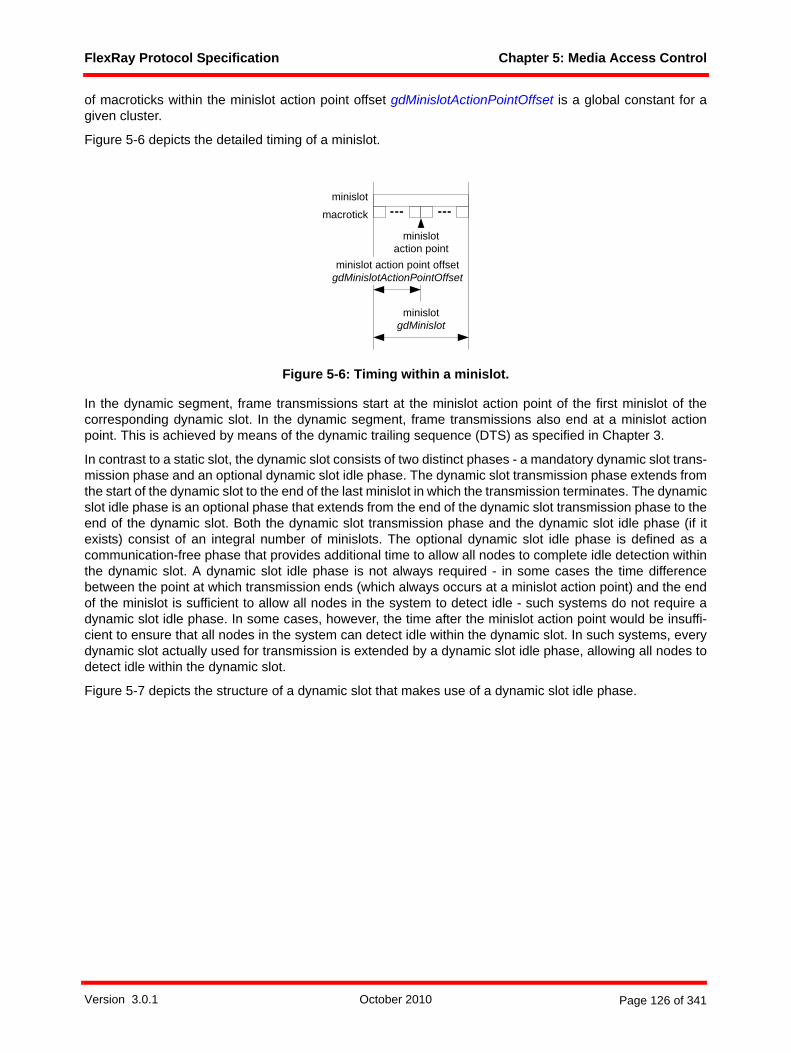
FlexRay Protocol Specification Chapter 5: Media Access Control
of macroticks within the minislot action point offset gdMinislotActionPointOffset is a global constant for agiven cluster.
Figure 5-6 depicts the detailed timing of a minislot.
Figure 5-6: Timing within a minislot.
In the dynamic segment, frame transmissions start at the minislot action point of the first minislot of thecorresponding dynamic slot. In the dynamic segment, frame transmissions also end at a minislot actionpoint. This is achieved by means of the dynamic trailing sequence (DTS) as specified in Chapter 3.
In contrast to a static slot, the dynamic slot consists of two distinct phases - a mandatory dynamic slot trans-mission phase and an optional dynamic slot idle phase. The dynamic slot transmission phase extends fromthe start of the dynamic slot to the end of the last minislot in which the transmission terminates. The dynamicslot idle phase is an optional phase that extends from the end of the dynamic slot transmission phase to theend of the dynamic slot. Both the dynamic slot transmission phase and the dynamic slot idle phase (if itexists) consist of an integral number of minislots. The optional dynamic slot idle phase is defined as acommunication-free phase that provides additional time to allow all nodes to complete idle detection withinthe dynamic slot. A dynamic slot idle phase is not always required - in some cases the time differencebetween the point at which transmission ends (which always occurs at a minislot action point) and the endof the minislot is sufficient to allow all nodes in the system to detect idle - such systems do not require adynamic slot idle phase. In some cases, however, the time after the minislot action point would be insuffi-cient to ensure that all nodes in the system can detect idle within the dynamic slot. In such systems, everydynamic slot actually used for transmission is extended by a dynamic slot idle phase, allowing all nodes todetect idle within the dynamic slot.
Figure 5-7 depicts the structure of a dynamic slot that makes use of a dynamic slot idle phase.
macrotick
minislot
minislotgdMinislot
minislot action point offsetgdMinislotActionPointOffset
minislotaction point
Version 3.0.1 October 2010 Page 126 of 341

FlexRay Protocol Specification Chapter 5: Media Access Control
Figure 5-7: Structure of dynamic slots.
The start of the dynamic segment requires particular attention. The first action point in the dynamic segmentoccurs gdActionPointOffset macroticks after the end of the static segment if gdActionPointOffset is largerthan gdMinislotActionPointOffset else it occurs gdMinislotActionPointOffset macroticks after the end of thestatic segment.73
The two cases are illustrated in Figure 5-8.
Figure 5-8: Timing at the boundary between the static and dynamic segments.
The node performs slot counter housekeeping on a per channel basis. At the end of every dynamic slot thenode generally increments the slot counter vSlotCounter by one.74 This is done until either
73 This ensures that the duration of the gap following the last static frame transmission is at least as large as the gaps between successive frames within the static segment.
74 Under special circumstances, the node may increase the slot counter by two to prevent a desynchronization of slot counters due to disturbances on the physical link.
dynamic slot (ds) ds
frame ID m+3
slot counter
ds
m m+1 m+2 m+3
slot counter incremented at the end of each dynamic slot
frame ID m
channel idle delimiter channel idlechannel active
dynamic slot
channel idledelimiterchannel active channel idle
minislot
minislot actionpoint
dynamic slottransmission phase
dynamic slottransmission phase
minislot actionpoint
dynamic slotidle phase
dynamic slotidle phase
gdActionPointOffset
macrotick
minislot
gdMinislot
gdMinislotActionPointOffset
minislotaction point
first dynamic slotlast static slot
gdActionPointOffset
macrotick
minislot
gdMinislot
gdMinislotActionPointOffset
minislotaction point
first dynamic slotlast static slot
(b)
gdActionPointOffset > gdMinislotActionPointOffset
(a)
gdActionPointOffset <= gdMinislotActionPointOffset
static segment static segmentdynamic segment dynamic segment
dynamic seg-ment offset
Version 3.0.1 October 2010 Page 127 of 341

FlexRay Protocol Specification Chapter 5: Media Access Control
1. the channel's slot counter has reached cSlotIDMax, or 2. the dynamic segment has reached the minislot gNumberOfMinislots, i.e. the end of the dynamic seg-
ment.
Once one of these conditions is met the node sets the corresponding slot counter to zero for the remainderof the communication cycle.
The arbitration procedure ensures that all fault-free receiving nodes implicitly know the dynamic slot in whichthe transmission starts. Further, all fault-free receiving nodes also agree implicitly on the minislot in whichslot counting is resumed. As a result, the slot counters of all fault-free receiving nodes match the slot counterof the fault-free transmitting node and the frame identifier contained in the frame.
The arbitration of the dynamic segment relies heavily on the assumption that all CE start, potential idle startand CHIRP signals are generated in response to legitimate frame transmissions by other nodes. Shoulddisturbances on the physical layer make it through the majority voting, this may be violated. As a conse-quence, it may occur that different nodes in the cluster have different notions of the slot counter value for agiven minislot. Such a situation can also arise, for example, if the BD of a node is temporarily preventedfrom reception during a portion of the dynamic segment (by overtemperature or undervoltage conditions, forexample). Dynamic segment desynchronization can also occur in certain situations where noise asymmet-rically affects reception in the dynamic segment.75 When slot counter desynchronization does occur in thedynamic segment its effect is limited to the specific instance of the dynamic segment. In other words, suchdesynchronization will not affect the operation of the static segment or the overall clock synchronization ofthe network, and will automatically be corrected at the end of the dynamic segment in which it occurred. Thesystem designer should be aware of the possibility that slot counter desynchronization could occur in thedynamic segment.
The MAC has the ability to correct certain fault scenarios where activity caused by noise on the physicallayer is shorter than cFrameThreshold bits and also short enough that both the start of the activity and theend of the idle detection following the activity both occur in a single minislot or within two adjacent minislots.If the MAC process detects such a noise event, it tries to revert to a state where it would have been if thenoise event did not occur. This may cause an increment of the slot counter by two, or in some cases mighteven cause a slot counter increment during a subsequent reception (see Figure 5-21). To increase therobustness of the cluster, a node is prohibited from transmitting in the dynamic slot following a slot in whicha noise event is detected.
5.1.5 Symbol windowWithin the symbol window a single symbol, either an MTS or a WUDOP, may be sent. Arbitration amongdifferent senders is not provided by the protocol for the symbol window. If arbitration among multiplesenders is required for the symbol window it has to be performed by means of a higher-level protocol.
Figure 5-9 outlines the media access scheme within the symbol window.
The number of macroticks per symbol window gdSymbolWindow is a global constant for a given cluster.The symbol window contains an action point that is offset from the start of the symbol window bygdSymbolWindowActionPointOffset macroticks. A symbol transmission starts at the action point within thesymbol window.
75 This can occur in some situations even though the MAC process in the dynamic segment has several mechanisms to prevent desynchronization when such noise exists.
Version 3.0.1 October 2010 Page 128 of 341
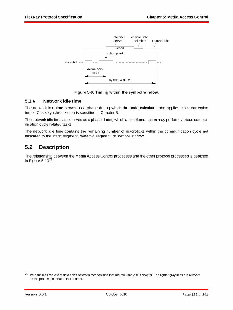
FlexRay Protocol Specification Chapter 5: Media Access Control
Figure 5-9: Timing within the symbol window.
5.1.6 Network idle timeThe network idle time serves as a phase during which the node calculates and applies clock correctionterms. Clock synchronization is specified in Chapter 8.
The network idle time also serves as a phase during which an implementation may perform various commu-nication cycle related tasks.
The network idle time contains the remaining number of macroticks within the communication cycle notallocated to the static segment, dynamic segment, or symbol window.
5.2 DescriptionThe relationship between the Media Access Control processes and the other protocol processes is depictedin Figure 5-1076.
76 The dark lines represent data flows between mechanisms that are relevant to this chapter. The lighter gray lines are relevant to the protocol, but not to this chapter.
symbol
macrotick
symbol window
action pointoffset
action point
channel idledelimiter channel idle
channelactive
Version 3.0.1 October 2010 Page 129 of 341

FlexRay Protocol Specification Chapter 5: Media Access Control
Figure 5-10: Media access control context.
In order to support two channels each node needs to contain a media access control process for channelA and a media access control process for channel B.
5.2.1 Operating modesThe protocol operation control process sets the operating mode of media access control for each commu-nication channel:
1. In the STANDBY mode media access is effectively halted. 2. In the NOCE mode the media access process is executed, but no frames or symbols are sent on the
channels.3. In the STARTUPFRAMECAS mode transmissions are restricted to the transmission of one startup null
frame per cycle on each configured channel in each key slot if the node is configured to send a startup frame. In addition the node sends an initial CAS symbol prior to the first communication cycle.
frame and symbolprocessing
media accesscontrol
clocksynchronization
startup
macrotickgeneration
clocksynchronization
processing
protocoloperation
control
controllerhost interface
coding / decodingprocesseschannel A
frame and symbolprocessingchannel A
media accesscontrol
channel A
clocksynchronization
startup channel A
to channel interface from channel interface
to / from host
mediaaccesscontrolchannel B
coding / decodingprocesseschannel B
frame andsymbolprocessingchannel B
clocksynchronization
startupchannel B
Version 3.0.1 October 2010 Page 130 of 341

FlexRay Protocol Specification Chapter 5: Media Access Control
4. In the STARTUPFRAME mode transmissions are restricted to the transmission of one startup null frame per cycle on each configured channel in each key slot if the node is configured to send a startup frame.
5. In the KEYSLOTONLY mode the transmissions are restricted based on the synchronization type of the cluster and the role of the node. Sync nodes in a TT-D cluster have transmissions restricted to one sync frame per cycle on each confgured channel. Coldstart nodes in a TT-E or TT-L cluster have transmissons restricted to two startup frames per cycle on each configured channel. Non-sync nodes in any cluster type have transmissions restricted to a single specified key slot frame77 per cycle on each configured channel.
6. In the ALL mode frames and symbols are sent in accordance with the node's transmission slot alloca-tion.
Definition 5-1 gives the formal definition of the MAC operating modes. newtype T_MacMode
literals STANDBY, NOCE, STARTUPFRAMECAS, STARTUPFRAME, KEYSLOTONLY, ALL;endnewtype;
Definition 5-1: Formal definition of T_MacMode.
5.2.2 Significant eventsWithin the context of media access control the node needs to react to a set of significant events. These arereception-related events, transmission-related events, and timing-related events.
5.2.2.1 Reception-related eventsFigure 5-11 depicts the reception-related events that are significant for media access control.
Figure 5-11: Reception-related events for MAC.
For communication channel A the reception-relevant events are:
1. communication element start on channel A (signal CE start on A, signal idle end on A),2. potential idle start on channel A (signal potential idle start on A),3. channel idle recognition point detected on channel A (signal CHIRP on A),4. DTS high bit received on channel A (signal DTS received on A, only in the dynamic segment), and,5. bit strobed on channel A (signal bit strobed on A, not shown in Figure 5-11).
For communication channel B the reception-relevant events are:
1. communication element start on channel B (signal CE start on B, signal idle end on B),2. potential idle start on channel B (signal potential idle start on B),
77 A node with pKeySlotID = 0 does not have a key slot, and thus will not transmit any frames when the MAC process is in the KEYSLOTONLY mode.
channel activechannel idlechannel idledelimiter channel idle
channel idlerecognition point
communication element start
potential idle start
(DTS received)
Version 3.0.1 October 2010 Page 131 of 341

FlexRay Protocol Specification Chapter 5: Media Access Control
3. channel idle recognition point detected on channel B (signal CHIRP on B),4. DTS high bit received on channel B (signal DTS received on B, only in the dynamic segment), and,5. bit strobed on channel B (signal bit strobed on B, not shown in Figure 5-11).
Note that the channel-specific BITSTRB processes will output a potential idle start signal every time a bitstrobed as high was preceded by a bit strobed as low. To keep the figure simple these signals are not shownin Figure 5-11 with the exception of the potential idle start at the end of channel activity.
5.2.2.2 Transmission-related eventsFigure 5-12 depicts the transmission-related events that are significant for media access control.
Figure 5-12: Transmission-related events for MAC.
For communication channel A the transmission-relevant events are:
1. the start of transmission ends the channel idle condition (signal idle end on A),2. the start of the dynamic trailing sequence within the transmission pattern on channel A (signal DTS
start on A).
For communication channel B the transmission-relevant events are:
1. the start of transmission ends the channel idle condition (signal idle end on B),2. the start of the dynamic trailing sequence within the transmission pattern on channel B (signal DTS
start on B).
5.2.2.3 Timing-related eventsBoth channels A and B are driven by the cycle start event that signals the start of each communication cycle(signal cycle start (vCycleCounter); where vCycleCounter provides the number of the current communi-cation cycle).
5.3 Media access control processThis section contains the formalized specification of the media access control process. The process isspecified for channel A, the process for channel B is equivalent.
For each communication channel the MAC process contains the following states:
1. a MAC:standby state,2. a MAC:wait for CAS action point state,3. a MAC:wait for the cycle start state,4. a MAC:wait for the action point state,5. a MAC:wait for the static slot boundary state,6. a MAC:wait for the AP transmission start state,7. a MAC:wait for the DTS start state,
channel activechannel idlechannel idledelimiter channel idle
DTS startidle end
Version 3.0.1 October 2010 Page 132 of 341

FlexRay Protocol Specification Chapter 5: Media Access Control
8. a MAC:wait for the AP transmission end state,9. a MAC:wait for the end of the dynamic segment state,10. a MAC:wait for the end of the minislot state,11. a MAC:wait for the end of activity state,12. a MAC:wait for the end of the dynamic slot state,13. a MAC:wait for the symbol window action point state, and14. a MAC:wait for the end of the symbol window state.
5.3.1 Initialization and MAC:standby stateFigure 5-13 depicts the specification of the media access process.
Version 3.0.1 October 2010 Page 133 of 341
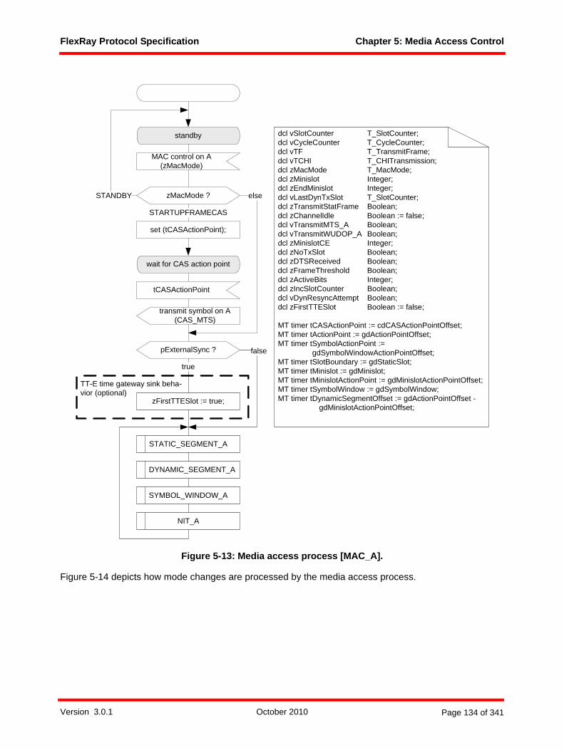
FlexRay Protocol Specification Chapter 5: Media Access Control
Figure 5-13: Media access process [MAC_A].
Figure 5-14 depicts how mode changes are processed by the media access process.
standby
MAC control on A(zMacMode)
zMacMode ?STANDBY
wait for CAS action point
set (tCASActionPoint);
transmit symbol on A (CAS_MTS)
STARTUPFRAMECAS
else
tCASActionPoint
STATIC_SEGMENT_A
DYNAMIC_SEGMENT_A
SYMBOL_WINDOW_A
NIT_A
dcl vSlotCounter T_SlotCounter;dcl vCycleCounter T_CycleCounter;dcl vTF T_TransmitFrame;dcl vTCHI T_CHITransmission;dcl zMacMode T_MacMode;dcl zMinislot Integer;dcl zEndMinislot Integer;dcl vLastDynTxSlot T_SlotCounter;dcl zTransmitStatFrame Boolean;dcl zChannelIdle Boolean := false;dcl vTransmitMTS_A Boolean;dcl vTransmitWUDOP_A Boolean;dcl zMinislotCE Integer;dcl zNoTxSlot Boolean;dcl zDTSReceived Boolean;dcl zFrameThreshold Boolean;dcl zActiveBits Integer;dcl zIncSlotCounter Boolean;dcl vDynResyncAttempt Boolean;dcl zFirstTTESlot Boolean := false;
MT timer tCASActionPoint := cdCASActionPointOffset;MT timer tActionPoint := gdActionPointOffset;MT timer tSymbolActionPoint :=
gdSymbolWindowActionPointOffset;MT timer tSlotBoundary := gdStaticSlot;MT timer tMinislot := gdMinislot;MT timer tMinislotActionPoint := gdMinislotActionPointOffset;MT timer tSymbolWindow := gdSymbolWindow;MT timer tDynamicSegmentOffset := gdActionPointOffset -
gdMinislotActionPointOffset;
pExternalSync ?
zFirstTTESlot := true;
true
false
TT-E time gateway sink beha-vior (optional)
Version 3.0.1 October 2010 Page 134 of 341
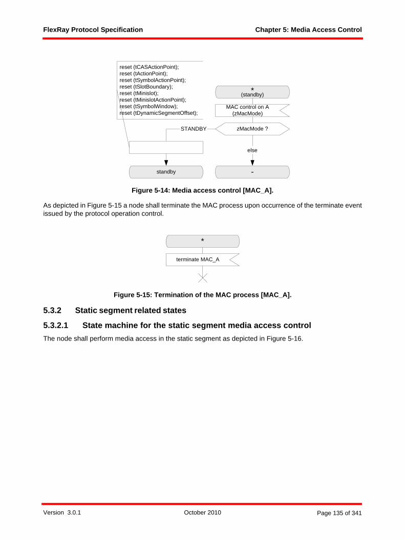
FlexRay Protocol Specification Chapter 5: Media Access Control
Figure 5-14: Media access control [MAC_A].
As depicted in Figure 5-15 a node shall terminate the MAC process upon occurrence of the terminate eventissued by the protocol operation control.
Figure 5-15: Termination of the MAC process [MAC_A].
5.3.2 Static segment related states
5.3.2.1 State machine for the static segment media access controlThe node shall perform media access in the static segment as depicted in Figure 5-16.
*(standby)
MAC control on A(zMacMode)
zMacMode ?
-standby
STANDBY
else
reset (tCASActionPoint);reset (tActionPoint);reset (tSymbolActionPoint);reset (tSlotBoundary);reset (tMinislot);reset (tMinislotActionPoint);reset (tSymbolWindow);reset (tDynamicSegmentOffset);
*
terminate MAC_A
Version 3.0.1 October 2010 Page 135 of 341

FlexRay Protocol Specification Chapter 5: Media Access Control
Figure 5-16: Media access in the static segment [MAC_A].
The node shall start frame transmission at the action point of an assigned static slot if appropriate trans-mission conditions are met (see section 5.3.2.2).
cycle start (vCycleCounter)
static segment start on A (vCycleCounter, vSlotCounter)
transmit frame on A(STATFRAME, vTF)
tActionPoint
tSlotBoundary
vSlotCounter ?
else
> gNumberOfStaticSlots
slot boundary on A(vSlotCounter)
STATIC_SEGMENT_A
ASSEMBLE_STATIC_FRAME_A
action point on A
frame vTF to transmit nothing totransmit
zTransmitStatFrame := true;
zTransmitStatFrame ?
true
set (tActionPoint);set (tSlotBoundary);zTransmitStatFrame := false;
vSlotCounter := 1;’update vSlotCounter on A in CHI’;
wait for the action point
vSlotCounter := vSlotCounter + 1;’update vSlotCounter on A in CHI’;
wait for the cycle start
false
wait for the static slotboundary
Version 3.0.1 October 2010 Page 136 of 341
FlexRay Protocol Specification Chapter 5: Media Access Control
The transmission data that shall be sent is specified in the T_TransmitFrame data structure that is definedin Definition 3-2. Definition 5-2 defines T_SlotCounter.syntype T_SlotCounter = Integer
constants 0 : 2047 endsyntype;
Definition 5-2: Formal definition of T_SlotCounter.
At the end boundary of every static slot the node shall increment the slot counter vSlotCounter for channelA and the slot counter vSlotCounter for channel B by one.
5.3.2.2 Transmission conditions and frame assembly in the static segment
The node shall assemble a frame for transmission in the static segment according to the macroASSEMBLE_STATIC_FRAME. The macro is depicted for channel A. Channel B is handled analogously.
In the static segment, whether or not a node shall transmit a frame depends on the current operating mode.
If media access is operating in the NOCE mode then the node shall transmit no frame.
If media access is operating in the STARTUPFRAMECAS mode or in the STARTUPFRAME mode then thenode shall transmit a frame on each configured channel if the communication slot is a key slot.
If media access is operating in the ALL mode then the node shall transmit a frame on a channel if the slotis assigned to the node for the channel.
Data elements are imported from the CHI based on the channel, the current value of the slot counter, andthe current value of the cycle counter. The CHI is assumed to return a data structure T_CHITransmissionthat is defined according to Definition 5-3.newtype T_CHITransmission struct
Assignment T_Assignment;TxMessageAvailable Boolean;PPIndicator T_PPIndicator;HeaderCRC T_HeaderCRC;Length T_Length;Message T_Payload;
endnewtype;
Definition 5-3: Formal definition of T_CHITransmission.
newtype T_Assignmentliterals UNASSIGNED, ASSIGNED;
endnewtype;
Definition 5-4: Formal definition of T_Assignment.
Assuming a variable vTCHI of type T_CHITransmission imported from the CHI, the node shall assemble theframe in the following way if vTCHI!Assignment is set to ASSIGNED:
1. The reserved bit shall be set to zero.2. If vSlotCounter equals pKeySlotID, or if pTwoKeySlotMode is true and vSlotCounter equals pSecond-
KeySlotID, then
a. the startup frame indicator shall be set in accordance with pKeySlotUsedForStartup, and
b. the sync frame indicator shall be set in accordance with pKeySlotUsedForSync.
Version 3.0.1 October 2010 Page 137 of 341

FlexRay Protocol Specification Chapter 5: Media Access Control
else
c. the startup frame indicator shall be set to zero, and
d. the sync frame indicator shall be set to zero.3. The frame ID field shall be set to the current value of the slot counter vSlotCounter.4. The length field shall be set to gPayloadLengthStatic.5. The header CRC shall be set to the value vTCHI!HeaderCRC retrieved from the CHI.6. The cycle count field shall be set to the current value of the cycle counter vCycleCounter.7. If the host has data available (vTCHI!TxMessageAvailable set to true) then
a. the null frame indicator shall be set to one, and
b. the payload preamble indicator shall be set to the value vTCHI!PPIndicator imported from the CHI,and
c. if gPayloadLengthStatic > vTCHI!Length then the vTCHI!Length number of two-byte payload wordsshall be copied from vTCHI!Message to vTF!Payload. The remaining (gPayloadLengthStatic -vTCHI!Length) two-byte payload words in vTF!Payload shall be set to the padding pattern 0x0000
else if gPayloadLengthStatic = vTCHI!Length then vTCHI!Length number of two-byte payload wordsshall be copied from vTCHI!Message to vTF!Payload
else the first gPayloadLengthStatic number of two-byte payload words shall be copied fromvTCHI!Message to vTF!Payload.
else if the host has no data available (vTCHI!TxMessageAvailable set to false) then
d. the null frame indicator shall be set to zero, and
e. the payload preamble indicator shall be set to zero, and
f. gPayloadLengthStatic number of two-byte payload words in vTF!Payload shall be set to the paddingpattern 0x0000.
Version 3.0.1 October 2010 Page 138 of 341
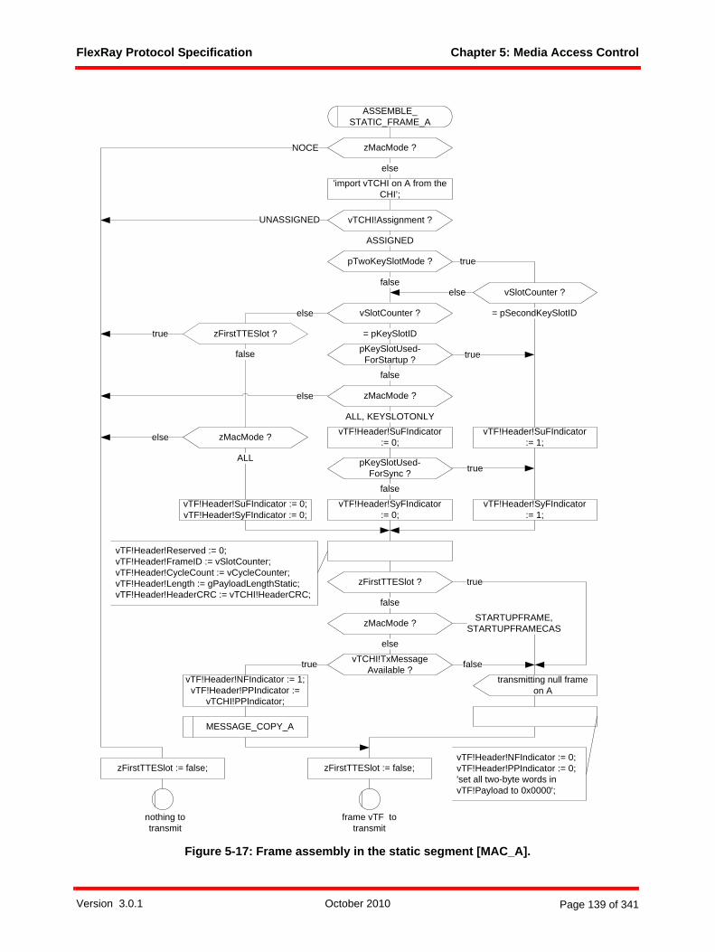
FlexRay Protocol Specification Chapter 5: Media Access Control
Figure 5-17: Frame assembly in the static segment [MAC_A].
UNASSIGNED
else
else
nothing totransmit
zMacMode ?
ALL
NOCE
ASSEMBLE_STATIC_FRAME_A
'import vTCHI on A from the CHI’;
zMacMode ?
ASSIGNED
else
vTCHI!Assignment ?
else
zMacMode ?
= pKeySlotIDpKeySlotUsed-
ForStartup ?false
true
ALL, KEYSLOTONLY
vTF!Header!SuFIndicator := 0;vTF!Header!SyFIndicator := 0;
false
vTF!Header!SuFIndicator := 1;
true
vTF!Header!SyFIndicator := 0;
vTF!Header!SyFIndicator := 1;
= pSecondKeySlotID
false
pKeySlotUsed-ForSync ?
vTF!Header!SuFIndicator := 0;
pTwoKeySlotMode ?
vSlotCounter ?
vSlotCounter ?
else
true
vTCHI!TxMessageAvailable ?
vTF!Header!NFIndicator := 1;vTF!Header!PPIndicator :=
vTCHI!PPIndicator;
true false
vTF!Header!Reserved := 0;vTF!Header!FrameID := vSlotCounter;vTF!Header!CycleCount := vCycleCounter;vTF!Header!Length := gPayloadLengthStatic;vTF!Header!HeaderCRC := vTCHI!HeaderCRC;
frame vTF totransmit
vTF!Header!NFIndicator := 0;vTF!Header!PPIndicator := 0;'set all two-byte words in vTF!Payload to 0x0000';
zMacMode ? STARTUPFRAME,STARTUPFRAMECAS
else
transmitting null frameon A
MESSAGE_COPY_A
zFirstTTESlot ?
false
true
zFirstTTESlot := false; zFirstTTESlot := false;
zFirstTTESlot ?
false
true
Version 3.0.1 October 2010 Page 139 of 341
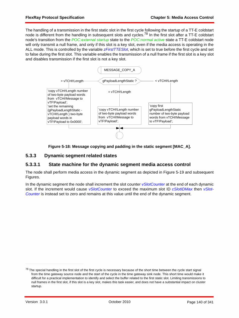
FlexRay Protocol Specification Chapter 5: Media Access Control
The handling of a transmission in the first static slot in the first cycle following the startup of a TT-E coldstartnode is different from the handling in subsequent slots and cycles.78 In the first slot after a TT-E coldstartnode's transition from the POC:external startup state to the POC:normal active state a TT-E coldstart nodewill only transmit a null frame, and only if this slot is a key slot, even if the media access is operating in theALL mode. This is controlled by the variable zFirstTTESlot, which is set to true before the first cycle and setto false during the first slot. This variable enables the transmission of a null frame if the first slot is a key slotand disables transmission if the first slot is not a key slot.
Figure 5-18: Message copying and padding in the static segment [MAC_A].
5.3.3 Dynamic segment related states
5.3.3.1 State machine for the dynamic segment media access control The node shall perform media access in the dynamic segment as depicted in Figure 5-19 and subsequentFigures.
In the dynamic segment the node shall increment the slot counter vSlotCounter at the end of each dynamicslot. If the increment would cause vSlotCounter to exceed the maximum slot ID cSlotIDMax then vSlot-Counter is instead set to zero and remains at this value until the end of the dynamic segment.
78 The special handling in the first slot of the first cycle is necessary because of the short time between the cycle start signal from the time gateway source node and the start of the cycle in the time gateway sink node. This short time would make it difficult for a practical implementation to identify and select the buffer related to the first static slot. Limiting transmissions to null frames in the first slot, if this slot is a key slot, makes this task easier, and does not have a substantial impact on cluster startup.
MESSAGE_COPY_A
gPayloadLengthStatic ?
’copy vTCHI!Length number of two-byte payload words from vTCHI!Message to vTF!Payload’;’set the remaining (gPayloadLengthStatic - vTCHI!Length ) two-byte payload words in vTF!Payload to 0x0000';
> vTCHI!Length
’copy vTCHI!Length number of two-byte payload words from vTCHI!Message to vTF!Payload’;
’copy first gPayloadLengthStatic number of two-byte payload words from vTCHI!Message to vTF!Payload’;
= vTCHI!Length
< vTCHI!Length
Version 3.0.1 October 2010 Page 140 of 341

FlexRay Protocol Specification Chapter 5: Media Access Control
Figure 5-19: Media access in the dynamic segment [MAC_A].
The macro DYN_SEG_LOOP keeps track of the dynamic slot counter during the dynamic segment (seeFigure 5-21).
At the start of each dynamic slot, the node checks whether there is still enough time left in the dynamicsegment for a transmission or if no transmission is allowed in this dynamic slot due to the detection of apossible slot counter desynchronization (as indicated by the variable zNoTxSlot). If a transmission isallowed, the node determines whether it has the right and need to transmit in the current dynamic slot and,if yes, does so. The transmission is described by the TRANSMIT_DYNAMIC_FRAME macro (see Figure 5-22).
If the node does not transmit itself, it awaits transmissions of other nodes in the MAC:wait for the end of theminislot state. Should no CE start signal be detected before the end of the minislot, the node proceeds tothe next dynamic slot. If a CE start signal is detected, the node notes the current minislot and starts to countthe bits of the incoming communication element. The length of the incoming transmission is used as anindication of whether the incoming communication element is a dynamic frame or perhaps induced noise onthe physical channel. Should the communication element end before the number of bits crosses thecFrameThreshold, the communication element is regarded as noise and the node tries to switch to a statewhere no noise was received. It does so by not applying the gdDynamicSlotIdlePhase lengthening of thedynamic slot on the one hand and by increasing the dynamic slot counter by two should a minislot boundaryhave occurred between the CE start signal and the CHIRP signal. The last potential idle start signal beforethe CHIRP signal marks the minislot in which the frame transmission ended, and is used to derive the lastminislot of the dynamic slot. A fault-free frame reception will also enable the detection of the DTS, which isindicated by the CODEC process with the DTS received signal. As soon as the DTS was received, the node
gNumberOfMinislots ? = 0
dynamic segment starton A (vSlotCounter)
gdActionPointOffset ?
set (tDynamicSegmentOffset);
> 0
> gdMinislotActionPointOffset
else
DYNAMIC_SEGMENT_A
DYN_SEG_LOOP_A
’update vLastDynTxSloton A in CHI’;
’update vDynResync-Attempt on A in CHI’;
set (tMinislotActionPoint);set (tMinislot);
*
-
tDynamicSegmentOffset
set (tMinislotActionPoint);set (tMinislot);
zMinislot := 1;vLastDynTxSlot := 0;zMinislotCE := 1;zNoTxSlot:= false;zActiveBits := 0;vDynResyncAttempt := false;
Version 3.0.1 October 2010 Page 141 of 341

FlexRay Protocol Specification Chapter 5: Media Access Control
locks down the end of the dynamic slot, with the intent that potential noise during the succeeding idledetection cannot affect the remaining dynamic slot length.
After the reception of the CHIRP signal, the node awaits the end of the dynamic slot. A CE start signal atthis point in time is generally an indication of a fault on the bus; either the preceding or the current commu-nication element was noise or a frame transmitted due to a fault condition. In case that the precedingelement was already categorized as noise due to its short length, the node treats the new communicationelement as frame and potentially adjusts the dynamic slot counter. Under normal circumstances (i.e., in thenoise-free case), no CE start signal will be received during the MAC:wait for the end of the dynamic slotstate and the dynamic slot will end at the end of the minislot where zMinislot is equal to zEndMinislot. Theend of the dynamic slot causes the dynamic slot counter to be incremented and then exported to the CHI.If the received communication element was shorter than the frame threshold cFrameThreshold and thedynamic slot was either one or two minislots long the node will abstain from transmitting in the followingdynamic slot and a resynchronization attempt is noted for indication to the CHI at the end of the dynamicsegment. If the received communication element was shorter than the frame threshold and the dynamic slotwas two minislots long the dynamic slot counter is incremented twice instead of just once, as is normally thecase.
Figure 5-20: Channel idle tracking [MAC_A].
*
-
idle end on A
zChannelIdle := false;
* (wait for the end of activity)
-
CHIRP on A
zChannelIdle := true;
Version 3.0.1 October 2010 Page 142 of 341
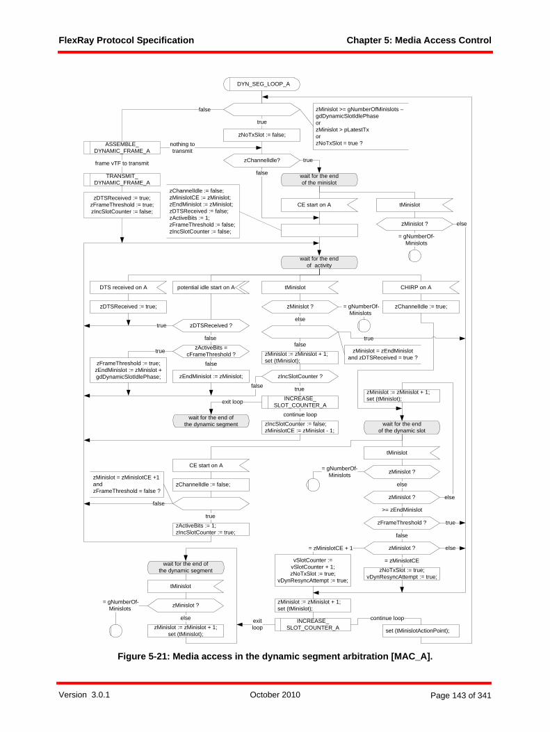
FlexRay Protocol Specification Chapter 5: Media Access Control
Figure 5-21: Media access in the dynamic segment arbitration [MAC_A].
ASSEMBLE_DYNAMIC_FRAME_A
false
set (tMinislotActionPoint);
wait for the end of the minislot
wait for the end of activity
CE start on A
CHIRP on A
tMinislot
tMinislot
zMinislot := zMinislot + 1;set (tMinislot);
zMinislot ?
else
else
zMinislot := zMinislot + 1;set (tMinislot);
true
nothing totransmit
frame vTF to transmit
= gNumberOf-Minislots
= gNumberOf-Minislots
DYN_SEG_LOOP_A
zMinislot >= gNumberOfMinislots – gdDynamicSlotIdlePhaseorzMinislot > pLatestTxorzNoTxSlot = true ?
zChannelIdle? true
false
wait for the end of the dynamic slot
tMinislot
zMinislot ?
zMinislot := zMinislot + 1;set (tMinislot);
else
zChannelIdle := true;
false
CE start on A
zChannelIdle := false;
zChannelIdle := false;zMinislotCE := zMinislot;zEndMinislot := zMinislot;zDTSReceived := false;zActiveBits := 1;zFrameThreshold := false;zIncSlotCounter := false;
TRANSMIT_DYNAMIC_FRAME_A
potential idle start on A
zFrameThreshold := true;zEndMinislot := zMinislot + gdDynamicSlotIdlePhase;
zActiveBits =cFrameThreshold ?true
zEndMinislot := zMinislot;
false
DTS received on A
zNoTxSlot := false;
>= zEndMinislot
zMinislot ?
= gNumberOf-Minislots
= zMinislotCE
= zMinislotCE + 1
zNoTxSlot := true;vDynResyncAttempt := true;
false
zMinislot ?
vSlotCounter := vSlotCounter + 1;zNoTxSlot := true;
vDynResyncAttempt := true;
else
zFrameThreshold ? true
true
zDTSReceived := true;
zMinislot ?
else
zDTSReceived := true;zFrameThreshold := true;zIncSlotCounter := false;
falsezMinislot = zEndMinislot
and zDTSReceived = true ?
zDTSReceived ?
false
true
true
zActiveBits := 1;zIncSlotCounter := true;
zIncSlotCounter ?
false true
zIncSlotCounter := false;zMinislotCE := zMinislot - 1;
INCREASE_SLOT_COUNTER_A
continue loop
INCREASE_SLOT_COUNTER_A
continue loop
zMinislot = zMinislotCE +1andzFrameThreshold = false ?
exit loop
exit loop
wait for the end of the dynamic segment
wait for the end of the dynamic segment
tMinislot
zMinislot := zMinislot + 1;set (tMinislot);
zMinislot ?
else
= gNumberOf-Minislots
Version 3.0.1 October 2010 Page 143 of 341

FlexRay Protocol Specification Chapter 5: Media Access Control
Figure 5-22: Transmission in the dynamic segment macro [MAC_A].
wait for the APtransmission start
tMinislotActionPoint
wait for the APtransmission end
wait for the DTS start
zEndMinislot := zMinislot + gdDynamicSlotIdlePhase;
tMinislotActionPoint
stop transmission on A
transmit frame on A (DYNFRAME, vTF)
DTS start on A tMinislotActionPoint
elsezMinislot ?
= gNumberOfMinislots -gdDynamicSlotIdlePhase
'set pLatestTx violation sta-tus indicator on A in CHI';
vLastDynTxSlot := vSlotCounter;
TRANSMIT_DYNAMIC_FRAME_A
tMinislot
zMinislot := zMinislot + 1;set (tMinislotActionPoint);set (tMinislot);
tMinislot
zMinislot := zMinislot + 1;set (tMinislotActionPoint);set (tMinislot);
Version 3.0.1 October 2010 Page 144 of 341

FlexRay Protocol Specification Chapter 5: Media Access Control
Figure 5-23: Slot counter increase macro [MAC_A].
The INCREASE_SLOT_COUNTER_A macro is called at the end of each dynamic slot to increase thedynamic slot counter and to communicate it to the CHI. If the dynamic slot counter were to surpass themaximum slot number cSlotIDMax, the slot counter shall not be incremented, but is instead reset to zero.The node shall then await the end of the dynamic segment.
Figure 5-24: Counting of active bits [MAC_A].
To categorize an incoming communication element as noise, the node determines whether it is shorter thanthe frame threshold cFrameThreshold.
5.3.3.2 Transmission conditions and frame assembly in the dynamic segment
The node shall assemble a frame for transmission in the dynamic segment according to the macroASSEMBLE_DYNAMIC_FRAME. The macro is depicted for channel A. Channel B is handled analogously.
In the dynamic segment, the node shall only transmit a frame on a channel if all following conditions arefulfilled:
• the media access is operating in the ALL mode,• the current minislot number is not larger than pLatestTx minislot (a node-specific upper bound),
INCREASE_SLOT_COUNTER_A
vSlotCounter ?
else
vSlotCounter := vSlotCounter + 1;’update vSlotCounter on A in CHI’;
vSlotCounter := 0;’update vSlotCounter on A in CHI’;
>= cSlotIDMax
slot boundary on A(vSlotCounter)
slot boundary on A(vSlotCounter)
exit loop continue loop
wait for the end of activity
zActiveBits := zActiveBits + 1;
bit strobed on A
-
zActiveBits ?
else
= cFrameThreshold
Version 3.0.1 October 2010 Page 145 of 341

FlexRay Protocol Specification Chapter 5: Media Access Control
• the slot is assigned to the node,• consistent payload data can be imported from the CHI, • transmission is not prohibited in the slot by the zNoTxSlot variable (i.e., zNoTxSlot was not set to
true in the previous slot), and• there is at least a number of minislots equivalent to gdDynamicSlotIdlePhase before the end of the
dynamic segment.
Assuming a variable vTCHI of type T_CHITransmission imported from the CHI the node shall assemble theframe in the following way if vTCHI!Assignment equals ASSIGNED and vTCHI!TxMessageAvailable equalstrue:
1. The reserved bit shall be set to zero.2. The sync frame indicator shall be set to zero.3. The startup frame indicator shall be set to zero.4. The payload preamble indicator shall be set to the value vTCHI!PPIndicator retrieved from the CHI.5. The frame ID field shall be set to the current value of the slot counter vSlotCounter.6. The length field shall be set to vTCHI!Length retrieved from the CHI.7. The header CRC shall be set to the value vTCHI!HeaderCRC retrieved from the CHI.8. The cycle count field shall be set to the current value of the cycle counter vCycleCounter.9. The null frame indicator shall be set to one.10. vTCHI!Length number of two-byte payload words shall be copied from vTCHI!Message to vTF!Pay-
load.
Figure 5-25: Frame assembly in the dynamic segment [MAC_A].
5.3.4 Symbol window related statesThe node shall perform media access in the symbol window as depicted in Figure 5-26. At the start of the symbol window the node shall set the slot counter vSlotCounter to zero. The node shallstart symbol transmission at the action point of the symbol window if the media access is in the ALL modeand if a symbol is released for transmission.
vTCHI!TxMessageAvailable ?false
vTF!Header!Reserved := 0;vTF!Header!SyFIndicator := 0;vTF!Header!SuFIndicator := 0;vTF!Header!FrameID := vSlotCounter;vTF!Header!CycleCount := vCycleCounter;vTF!Header!Length := vTCHI!Length;vTF!Header!HeaderCRC := vTCHI!HeaderCRC;vTF!Header!PPIndicator := vTCHI!PPIndicator;vTF!Header!NFIndicator := 1;'copy vTCHI!Length number of two-byte payload words from vTCHI!Message to vTF!Payload';
zMacMode ?else
ALL
true
ASSEMBLE_DYNAMIC_FRAME_A
nothing totransmit
frame vTF totransmit
'import vTCHI on A from the CHI’
ASSIGNED
vTCHI!Assignment ?else
Version 3.0.1 October 2010 Page 146 of 341
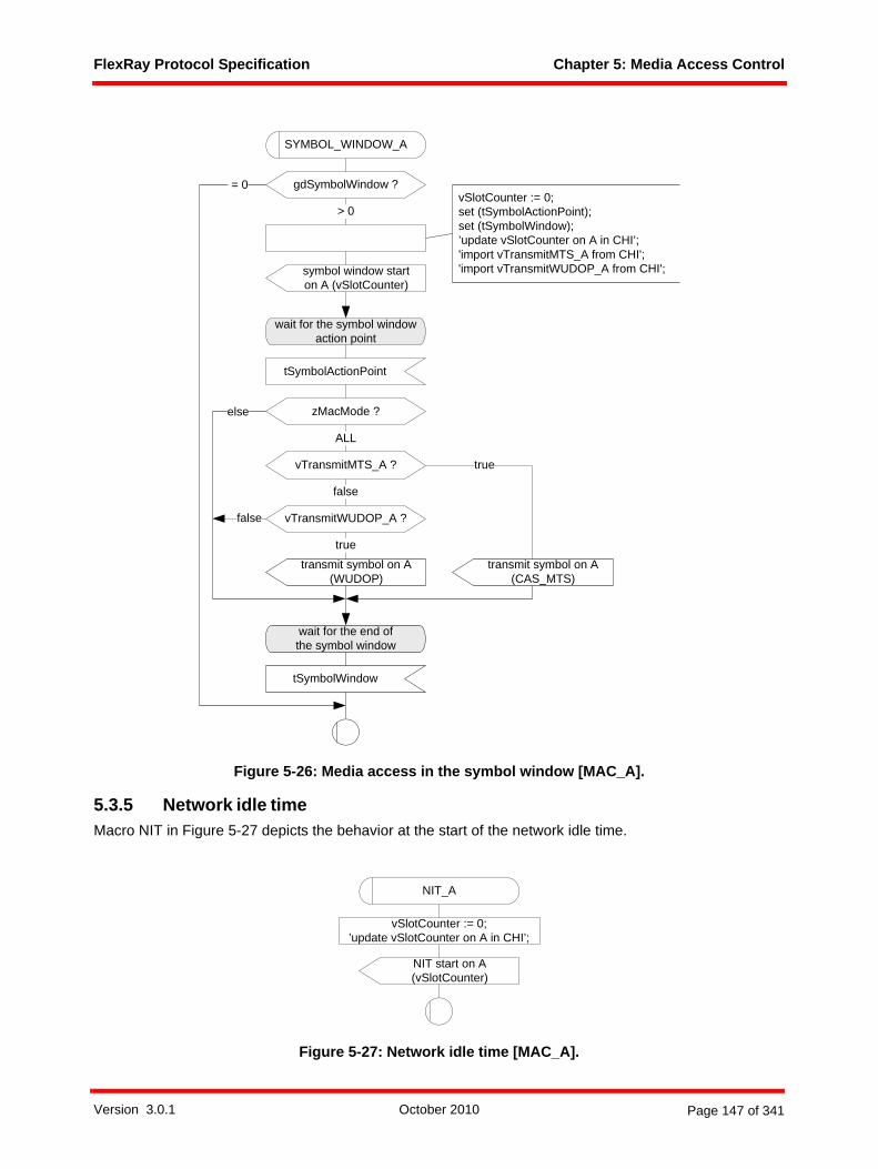
FlexRay Protocol Specification Chapter 5: Media Access Control
Figure 5-26: Media access in the symbol window [MAC_A].
5.3.5 Network idle timeMacro NIT in Figure 5-27 depicts the behavior at the start of the network idle time.
Figure 5-27: Network idle time [MAC_A].
false
zMacMode ?
transmit symbol on A (WUDOP)
ALL
else
wait for the end of the symbol window
tSymbolWindow
gdSymbolWindow ? = 0
> 0
symbol window starton A (vSlotCounter)
SYMBOL_WINDOW_A
wait for the symbol windowaction point
tSymbolActionPoint
transmit symbol on A (CAS_MTS)
truevTransmitMTS_A ?
false
vSlotCounter := 0;set (tSymbolActionPoint);set (tSymbolWindow);’update vSlotCounter on A in CHI’;'import vTransmitMTS_A from CHI';'import vTransmitWUDOP_A from CHI';
vTransmitWUDOP_A ?
true
NIT start on A (vSlotCounter)
vSlotCounter := 0;’update vSlotCounter on A in CHI’;
NIT_A
Version 3.0.1 October 2010 Page 147 of 341

FlexRay Protocol Specification Chapter 5: Media Access Control
At the start of the NIT the node shall set the slot counter vSlotCounter to zero.
Version 3.0.1 October 2010 Page 148 of 341
FlexRay Protocol Specification Chapter 6: Frame and Symbol Processing
Chapter 6Frame and Symbol Processing
This chapter defines how the node shall perform frame and symbol processing.
6.1 PrinciplesFrame and symbol processing (FSP) is the main processing layer between frame and symbol decoding,which is specified in Chapter 3, and the controller host interface, which is specified in Chapter 9.
Frame and symbol processing checks the correct timing of frames and symbols with respect to the TDMAscheme, applies further syntactical tests to received frames, and checks the semantic correctness ofreceived frames.
6.2 DescriptionThe relationship between the Frame and Symbol Processing processes and the other protocol processesis depicted in Figure 6-179.
79 The dark lines represent data flows between mechanisms that are relevant to this chapter. The lighter gray lines are relevant to the protocol, but not to this chapter.
Version 3.0.1 October 2010 Page 149 of 341

FlexRay Protocol Specification Chapter 6: Frame and Symbol Processing
Figure 6-1: Frame and symbol processing context.
In order to support two channels each node needs to contain a frame and symbol processing process forchannel A and a frame and symbol processing process for channel B.
6.2.1 Operating modesThe protocol operation control process sets the operating mode of frame and symbol processing for eachcommunication channel:
1. In the STANDBY mode the execution of the frame and symbol processing process shall be halted.2. In the STARTUP mode the frame and symbol processing process shall be executed but no update of
the CHI takes place, except for decoded wakeup patterns.3. In the GO mode the frame and symbol processing process shall be executed and the update of the
CHI takes place.
Definition 6-1 gives the formal definition of the FSP operating modes.newtype T_FspMode
frame and symbolprocessing
media accesscontrol
clocksynchronization
startup
macrotickgeneration
clocksynchronization
processing
protocoloperation
control
controllerhost interface
coding / decodingprocesseschannel A
frame and symbolprocessingchannel A
media accesscontrol
channel A
clocksynchronization
startup channel A
to channel interface from channel interface
to / from host
mediaaccesscontrolchannel B
coding / decodingprocesseschannel B
frame andsymbolprocessingchannel B
clocksynchronization
startupchannel B
Version 3.0.1 October 2010 Page 150 of 341

FlexRay Protocol Specification Chapter 6: Frame and Symbol Processing
literals STANDBY, STARTUP, GO;endnewtype;
Definition 6-1: Formal definition of T_FspMode.
6.2.2 Significant eventsWithin the context of frame and symbol processing the node needs to react to a set of significant events.These are reception-related events, decoding-related events, and timing-related events.
6.2.2.1 Reception-related eventsFigure 6-2 depicts the reception-related events that are significant for frame and symbol processing.
Figure 6-2: Reception-related events for FSP.
For communication channel A the reception-related events are
1. communication element start on channel A (signal CE start on A),2. frame decoded on channel A (signal frame decoded on A (vRF), where vRF provides the timestamp of
the primary time reference point and the header as well as the payload of the received frame as defined in Definition 3-10),
3. CAS or MTS decoded on channel A (signal CAS_MTS decoded on A),4. decoding error on channel on A (signal decoding error on A (zDecodingError)),5. channel idle recognition point detected on channel A (signal CHIRP on A),
6. content error on channel B (signal content error on B)80,7. wakeup decoded on channel A (signal wakeup decoded on A).
For communication channel B the reception-related events are
1. communication element start on channel B (signal CE start on B),2. frame decoded on channel B (signal frame decoded on B (vRF), where vRF provides the timestamp of
the primary time reference point and the header as well as the payload of the received frame as defined in Definition 3-10),
3. CAS or MTS decoded on channel B (signal CAS_MTS decoded on B),4. decoding error on channel B (signal decoding error on B (zDecodingError)),5. channel idle recognition point detected on channel B (signal CHIRP on B),6. content error on channel A (signal content error on A),7. wakeup decoded on channel B (signal wakeup decoded on B).
Definition 3-10 gives the formal definition of the T_ReceiveFrame data structure.
80 In order to address channel consistency checks for sync frames.
channel idlerecognition point
communication element start
frame decodedor
CAS/MTS decodedor
decoding error
channel activechannel idlechannel idle
delimiter channel idle
wakeup decoded
Version 3.0.1 October 2010 Page 151 of 341

FlexRay Protocol Specification Chapter 6: Frame and Symbol Processing
6.2.2.2 Decoding-related eventsFor communication channel A the decoding-related events are
1. decoding halted on channel A (signal decoding halted on A),2. decoding started on channel A (signal decoding started on A).
For communication channel B the decoding-related events are
1. decoding halted on channel B (signal decoding halted on B),2. decoding started on channel B (signal decoding started on B).
6.2.2.3 Timing-related eventsFigure 6-3 depicts the timing-related events that are significant for frame and symbol processing.
Figure 6-3: Timing-related events for FSP.
For communication channel A the relevant events are
1. static segment start on channel A (signal static segment start on A (vCycleCounter, vSlotCounter); where vCycleCounter holds the number of the current communication cycle and vSlotCounter holds the number of the communication slot that is just beginning on channel A),
2. slot boundary on channel A (signal slot boundary on A (vSlotCounter); where vSlotCounter holds the number of the communication slot that is just beginning on channel A),
3. dynamic segment start on channel A (signal dynamic segment start on A (vSlotCounter); where vSlot-Counter holds the number of the current communication slot on channel A),
4. symbol window start on channel A (signal symbol window start on A (vSlotCounter); where vSlot-Counter holds the value 0),
5. network idle time (NIT) start on channel A (signal NIT start on A (vSlotCounter); where vSlotCounter holds the value 0).
For communication channel B the relevant events are
1. static segment start on channel B (signal static segment start on B (vCycleCounter, vSlotCounter); where vCycleCounter holds the number of the current communication cycle and vSlotCounter holds the number of the communication slot that is just beginning on channel B),
2. slot boundary on channel B (signal slot boundary on B (vSlotCounter); where vSlotCounter holds the number of the communication slot that is just beginning on channel B),
3. dynamic segment start on channel B (signal dynamic segment start on B (vSlotCounter); where vSlot-Counter holds the number of the current communication slot on channel B),
staticsegment
start
staticsegment
start
slotboundary
dynamicsegment
start
slotboundaries
symbolwindow
start
communication cycle
slotboundary
staticslot
staticslot
dynamicslot
dynamicslot
dynamicslot
symbolwindow
networkidletime
NITstart
Version 3.0.1 October 2010 Page 152 of 341

FlexRay Protocol Specification Chapter 6: Frame and Symbol Processing
4. symbol window start on channel B (signal symbol window start on B (vSlotCounter); where vSlot-Counter holds the value 0),
5. network idle time (NIT) start on channel B (signal NIT start on B (vSlotCounter); where vSlotCounter holds the value 0).
6.2.3 Status dataFor each communication channel the node shall provide a slot status that is updated in the CHI as specifiedin Chapter 9.
Definition 6-2 gives the formal definition of the slot status.newtype T_SlotStatusstruct
Channel T_Channel;SlotCount T_SlotCounter;CycleCount T_CycleCounter;ValidFrame Boolean;ValidMTS Boolean;SyntaxError Boolean;ContentError Boolean;BViolation Boolean;FrameSent Boolean;TxConflict Boolean;NFIndicator T_NFIndicator;Segment T_Segment;
endnewtype;
Definition 6-2: Formal definition of T_SlotStatus.
The slot status consists of the following elements:• Channel identifies the corresponding channel of the other slot status elements.• SlotCount holds the value of the slot counter of the corresponding slot.• CycleCount holds the value of the cycle counter of the corresponding cycle.• ValidFrame denotes whether a valid frame was received in a slot of the static or dynamic segment.
The element is set to false if no valid frame was received (or if a frame was transmitted in the slot), orto true if a valid frame was received.
• ValidMTS denotes whether a valid MTS was received in the symbol window. The element is set tofalse if no valid MTS was received, or to true if a valid MTS was received.
• SyntaxError denotes whether a syntax error has occurred. A syntax error occurs if any of thefollowing criteria are met:
1. the node starts transmitting while the channel is not in the idle state, 2. a decoding error occurs, 3. a frame is decoded in the symbol window or in the network idle time, 4. a CAS/MTS is decoded in the static segment, in the dynamic segment, or in the network idle time, 5. a frame is received within the slot after the reception of a semantically correct frame, 6. an otherwise valid frame is received before transmission in a slot that is used for transmission, 7. a syntactically valid frame is detected after transmission in a slot that is used for transmission.
Version 3.0.1 October 2010 Page 153 of 341

FlexRay Protocol Specification Chapter 6: Frame and Symbol Processing
This element is set to false if no syntax error occurred, or to true if a syntax error did occur. Note, it ispossible to have SyntaxError = true and ValidFrame = true. This could occur, for example, if asyntactically incorrect frame is received first, followed by a semantically correct and syntacticallycorrect frame in the same slot. This would result in ValidFrame = true, SyntaxError = true, andContentError = false.
• ContentError denotes whether a content error has occurred. A content error occurs if any of thefollowing criteria are met:
1. in the static segment the header length contained in the header of the received frame does not match the stored header length in gPayloadLengthStatic,
2. in the static segment the startup frame indicator contained in the header of the received frame is set to one while the sync frame indicator is set to zero,
3. in the static segment the null frame indicator contained in the header of the received frame is set to zero and the payload preamble indicator is set to one,
4. in the static or in the dynamic segment the frame ID contained in the header of the received frame does not match the current value of the slot counter or the frame ID equals zero in the dynamic segment,
5. in the static or in the dynamic segment the cycle count contained in the header of the received frame does not match the current value of the cycle counter,
6. in the dynamic segment the sync frame indicator contained in the header of the received frame is set to one,
7. in the dynamic segment the startup frame indicator contained in the header of the received frame is set to one,
8. in the dynamic segment the null frame indicator contained in the header of the received frame is set to zero.
This element is set to false if no content error occurred, or to true if a content error did occur. Note - it is possible to have ContentError = true and ValidFrame = true. This could occur, for example, if a syntactically correct but semantically incorrect frame is received first, followed by a semantically correct and syntactically correct frame in the same slot. This would result in ValidFrame = true, SyntaxError = false, and ContentError = true.
• BViolation denotes whether a boundary violation occurred at either beginning or end of the corres-ponding slot. A boundary violation occurs if the node does not consider the channel to be idle at the boundary of a slot. The element is set to false if no boundary violation occurred. See Table 9-2 for a description of the meaning of various combinations of ValidFrame, SyntaxError, ContentError, and BViolation.
• FrameSent denotes whether a non-null frame was completely transmitted in the corresponding slot. The element is set to true if there was a complete non-null frame transmission in the slot, and otherwise it is set to false.
• TxConflict denotes whether reception was ongoing at the time the node started a transmission. The element is set to false if reception was not ongoing, or to true if reception was ongoing.
• NFIndicator denotes whether a null frame was received. The element is set to 0 if either a null frame, an invalid frame or nothing was received, or to 1 if a valid non-null frame was received.81
• Segment denotes the segment in which the slot status was recorded. Its type is defined in Definition 6-3.
newtype T_Segmentliterals STUP, STATIC, DYNAMIC, SW, NIT;
81 The parameter NFIndicator is always set to 1 for valid frames in the dynamic segment.
Version 3.0.1 October 2010 Page 154 of 341
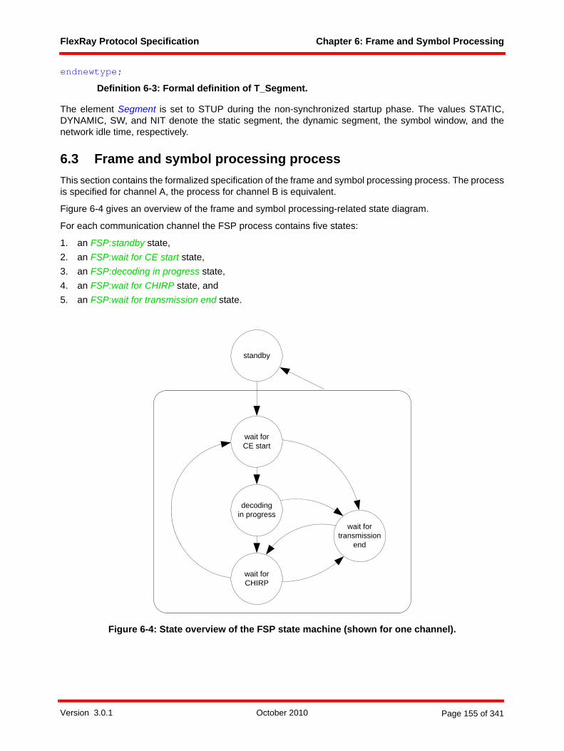
FlexRay Protocol Specification Chapter 6: Frame and Symbol Processing
endnewtype;
Definition 6-3: Formal definition of T_Segment.
The element Segment is set to STUP during the non-synchronized startup phase. The values STATIC,DYNAMIC, SW, and NIT denote the static segment, the dynamic segment, the symbol window, and thenetwork idle time, respectively.
6.3 Frame and symbol processing processThis section contains the formalized specification of the frame and symbol processing process. The processis specified for channel A, the process for channel B is equivalent.
Figure 6-4 gives an overview of the frame and symbol processing-related state diagram.
For each communication channel the FSP process contains five states:
1. an FSP:standby state,2. an FSP:wait for CE start state,3. an FSP:decoding in progress state,4. an FSP:wait for CHIRP state, and5. an FSP:wait for transmission end state.
Figure 6-4: State overview of the FSP state machine (shown for one channel).
wait forCE start
decodingin progress
wait forCHIRP
wait fortransmission
end
standby
Version 3.0.1 October 2010 Page 155 of 341

FlexRay Protocol Specification Chapter 6: Frame and Symbol Processing
6.3.1 Initialization and FSP:standby stateAs depicted in Figure 6-5, the node shall initially enter the FSP:standby state of the FSP process and waitfor an FSP mode change initiated by the protocol operation control process.
A node shall leave the FSP:standby state if the protocol operation control process sets the FSP mode toSTARTUP or to GO.
Figure 6-5: FSP process [FSP_A].
As depicted in Figure 6-6, a node shall enter the FSP:standby state from any state within the FSP process(with the exception of the FSP:standby state itself) if the protocol operation control process sets the FSPprocess to the STANDBY mode.
Figure 6-6: FSP control [FSP_A].
else
standby
FSP control on A (zFspMode)
zFspMode ?STANDBY
wait for CE start
dcl zContentErrorOnB Boolean;dcl zNullframe Boolean;dcl zTransmit Boolean;dcl zFspMode T_FspMode;dcl zSegment T_Segment;dcl vSS T_SlotStatus;dcl vRF T_ReceiveFrame;dcl zRF T_ReceiveFrame;dcl vSlotCounter T_SlotCounter;dcl vCycleCounter T_CycleCounter;dcl zDecodingError T_DecodingError;
vSS!Channel := A;vSS!ValidFrame := false;vSS!ValidMTS := false;vSS!SyntaxError := false;vSS!ContentError := false;vSS!BViolation := false;vSS!NFIndicator := 0;vSS!FrameSent := false;vSS!TxConflict := false;vSS!SlotCount := 0;vSS!CycleCount := 0;vSS!Segment := STUP;zSegment := STUP;vSlotCounter := 0;vCycleCounter := 0;zContentErrorOnB := false;zNullframe := false;zTransmit := false;
*(standby)
FSP control on A(zFspMode)
zFspMode ?
-standby
STANDBY
else
content error on B
zContentErrorOnB := true;
transmitting null frameon A
zNullframe := true;
Version 3.0.1 October 2010 Page 156 of 341

FlexRay Protocol Specification Chapter 6: Frame and Symbol Processing
In addition, the node shall apply cross-channel content checks to identify cross-channel inconsistencieswhenever zSegment = STATIC.82
As depicted in Figure 6-7, a node shall terminate the FSP process upon occurrence of the terminate eventissued by the protocol operation control process.
Figure 6-7: Termination of the FSP process [FSP_A].
Depending on the operation mode of the FSP process and the segment, the FSP process relays decodedwakeup patterns from the WUPDEC process to the CHI as shown in Figure 6-8.
Figure 6-8: CHI update of a decoded wakeup pattern [FSP_A].
6.3.2 Macro SLOT_SEGMENT_ENDThe macro SLOT_SEGMENT_END that is depicted in Figure 6-9 shall be called within the FSP process
1. at the end of each static slot,2. at the end of each dynamic slot if a dynamic segment is configured (i.e., gNumberOfMinislots > 0),3. at the end of the symbol window if the symbol window is configured (i.e., gdSymbolWindow > 0), and4. at the end of the network idle time.
If a valid frame was received, the sync frame indicator of the received frame is set, and no content error wasdetected on the other channel a node shall assert valid sync frame on A (vRF). Such a frame is called avalid sync frame.
If the FSP process is in the GO mode a node shall make the slot status vSS and received frame data vRFavailable to the CHI.
82 zSegment is STATIC during the static segment in normal operation, but can also be STATIC during some portions of startup.
*
terminate FSP_A
*
wakeup decoded on A
zFspMode ?
GO
zSegment ?
SW, NIT else
else
’set wakeup receivedindicator on A in CHI’;
-
Version 3.0.1 October 2010 Page 157 of 341
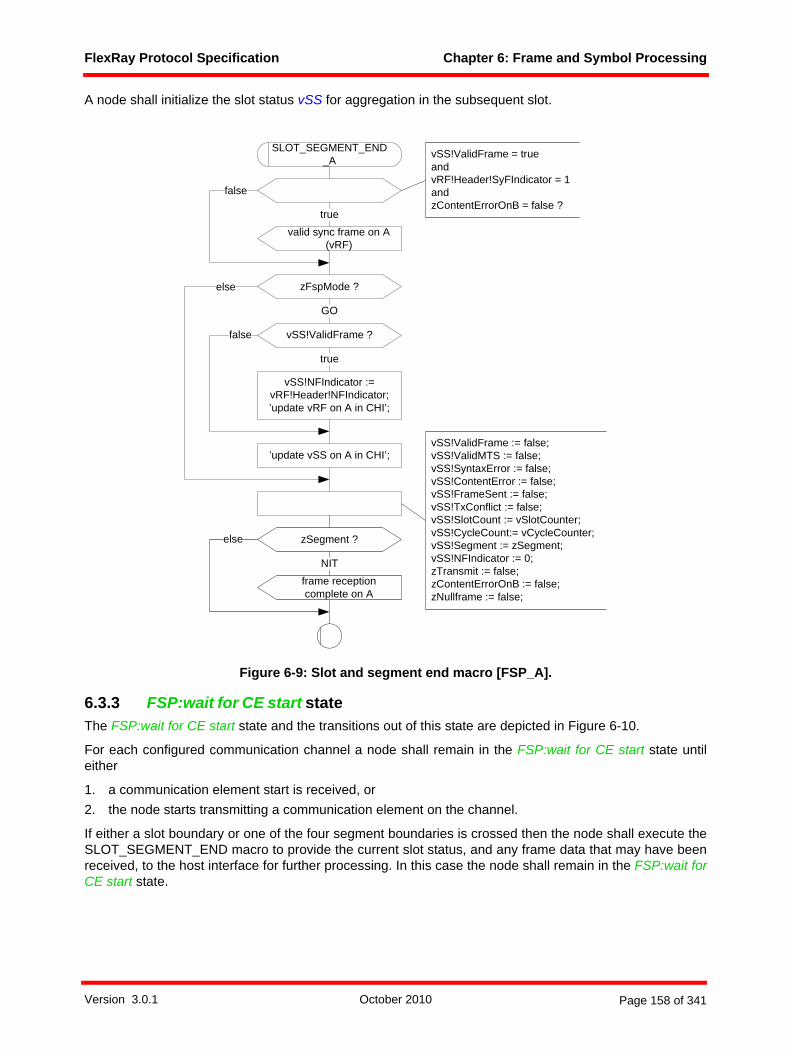
FlexRay Protocol Specification Chapter 6: Frame and Symbol Processing
A node shall initialize the slot status vSS for aggregation in the subsequent slot.
Figure 6-9: Slot and segment end macro [FSP_A].
6.3.3 FSP:wait for CE start state The FSP:wait for CE start state and the transitions out of this state are depicted in Figure 6-10.
For each configured communication channel a node shall remain in the FSP:wait for CE start state untileither
1. a communication element start is received, or2. the node starts transmitting a communication element on the channel.
If either a slot boundary or one of the four segment boundaries is crossed then the node shall execute theSLOT_SEGMENT_END macro to provide the current slot status, and any frame data that may have beenreceived, to the host interface for further processing. In this case the node shall remain in the FSP:wait forCE start state.
vSS!ValidFrame := false;vSS!ValidMTS := false;vSS!SyntaxError := false;vSS!ContentError := false;vSS!FrameSent := false;vSS!TxConflict := false;vSS!SlotCount := vSlotCounter;vSS!CycleCount:= vCycleCounter;vSS!Segment := zSegment;vSS!NFIndicator := 0;zTransmit := false;zContentErrorOnB := false;zNullframe := false;
SLOT_SEGMENT_END_A
false
valid sync frame on A(vRF)
true
vSS!ValidFrame = trueandvRF!Header!SyFIndicator = 1andzContentErrorOnB = false ?
zFspMode ?
’update vSS on A in CHI’;
GO
else
zSegment ?
frame reception complete on A
NIT
else
vSS!ValidFrame ?
true
false
vSS!NFIndicator := vRF!Header!NFIndicator;’update vRF on A in CHI’;
Version 3.0.1 October 2010 Page 158 of 341

FlexRay Protocol Specification Chapter 6: Frame and Symbol Processing
Figure 6-10: Transitions from the FSP:wait for CE start state [FSP_A].
6.3.4 FSP:decoding in progress stateThe FSP:decoding in progress state and the transitions out of this state are depicted in Figure 6-11 andFigure 6-12.
For each configured communication channel a node shall remain in the FSP:decoding in progress state untileither
1. the node starts transmitting on the communication channel, or2. a decoding error occurs on the communication channel, or3. a syntactically correct frame is decoded on the communication channel, or4. a CAS/MTS symbol was decoded, or5. a slot boundary or one of the four segment boundaries is crossed.
If either a slot boundary or one of the four segment boundaries is crossed then the node shall execute theSLOT_SEGMENT_END macro to provide the current slot status, and any frame data that may have beenreceived, to the host interface for further processing.
symbol window starton A (vSlotCounter)
NIT start on A(vSlotCounter)
wait for CE start
zSegment := SW; zSegment := NIT;
vSS!BViolation := false;
wait for CE start
CE start on A
decoding in progress wait for transmission end
dynamic segment starton A (vSlotCounter)
zSegment := DYNAMIC;
static segment start on A(vCycleCounter, vSlotCounter)
slot boundary on A(vSlotCounter)
zSegment := STATIC;
SLOT_SEGMENT_END_A
decoding halted on A
Version 3.0.1 October 2010 Page 159 of 341
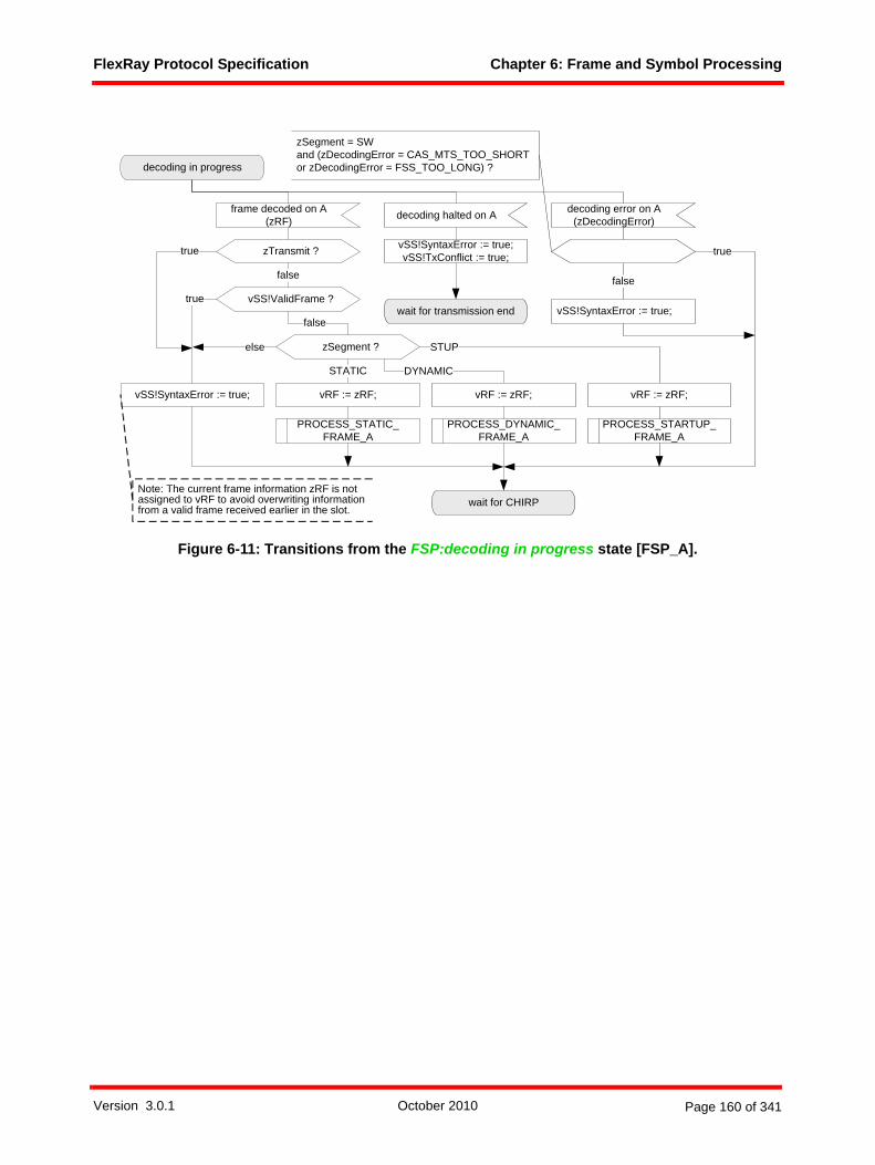
FlexRay Protocol Specification Chapter 6: Frame and Symbol Processing
Figure 6-11: Transitions from the FSP:decoding in progress state [FSP_A].
decoding error on A(zDecodingError)
frame decoded on A(zRF)
decoding in progress
wait for CHIRP
decoding halted on A
PROCESS_STATIC_FRAME_A
STATIC
vSS!SyntaxError := true;
vSS!SyntaxError := true;vSS!TxConflict := true;
false
PROCESS_DYNAMIC_FRAME_A
DYNAMIC
PROCESS_STARTUP_FRAME_A
STUP
wait for transmission endvSS!ValidFrame ?
zSegment ?
false
vSS!SyntaxError := true;
else
true
vRF := zRF; vRF := zRF; vRF := zRF;
Note: The current frame information zRF is not assigned to vRF to avoid overwriting information from a valid frame received earlier in the slot.
true
zSegment = SWand (zDecodingError = CAS_MTS_TOO_SHORTor zDecodingError = FSS_TOO_LONG) ?
zTransmit ?
false
true
Version 3.0.1 October 2010 Page 160 of 341

FlexRay Protocol Specification Chapter 6: Frame and Symbol Processing
Figure 6-12: Transitions from the FSP:decoding in progress state [FSP_A].
6.3.4.1 Frame reception checks during non-synchronized operationThe frame acceptance checks that the node shall apply during non-synchronized operation are defined inthe macro PROCESS_STARTUP_FRAME depicted in Figure 6-13.
For each configured communication channel the node shall accept each frame that fulfills all of the followingcriteria:
1. The frame ID included in the header of the frame is greater than 0 and not larger than the number of the last static slot gNumberOfStaticSlots.
2. The payload length included in the header of the frame equals the globally configured length for static frames gPayloadLengthStatic.
3. The sync frame indicator included in the header is set to one.4. The startup frame indicator included in the header is set to one.5. If the null frame indicator vRF!Header!NFIndicator is set to zero then the vRF!Header!PPIndicator is
not set to one.6. The cycle counter included in the header of the frame is not larger than the configured maximum cycle
counter gCycleCountMax.
static segmentstart on A(vCycleCounter,vSlotCounter)
dynamic segment starton A (vSlotCounter)
symbol window starton A (vSlotCounter)
NIT start on A(vSlotCounter)
CAS_MTS decoded on A
wait for CHIRP
vSS!ValidMTS := true;
SW
zSegment := DYNAMIC; zSegment := SW; zSegment := NIT;
vSS!SyntaxError := true;
else
vSS!BViolation:= true;
zSegment := STATIC;
slot boundaryon A (vSlotCounter)
SLOT_SEGMENT_END_A
decoding in progress
STUPzSegment ?
Version 3.0.1 October 2010 Page 161 of 341
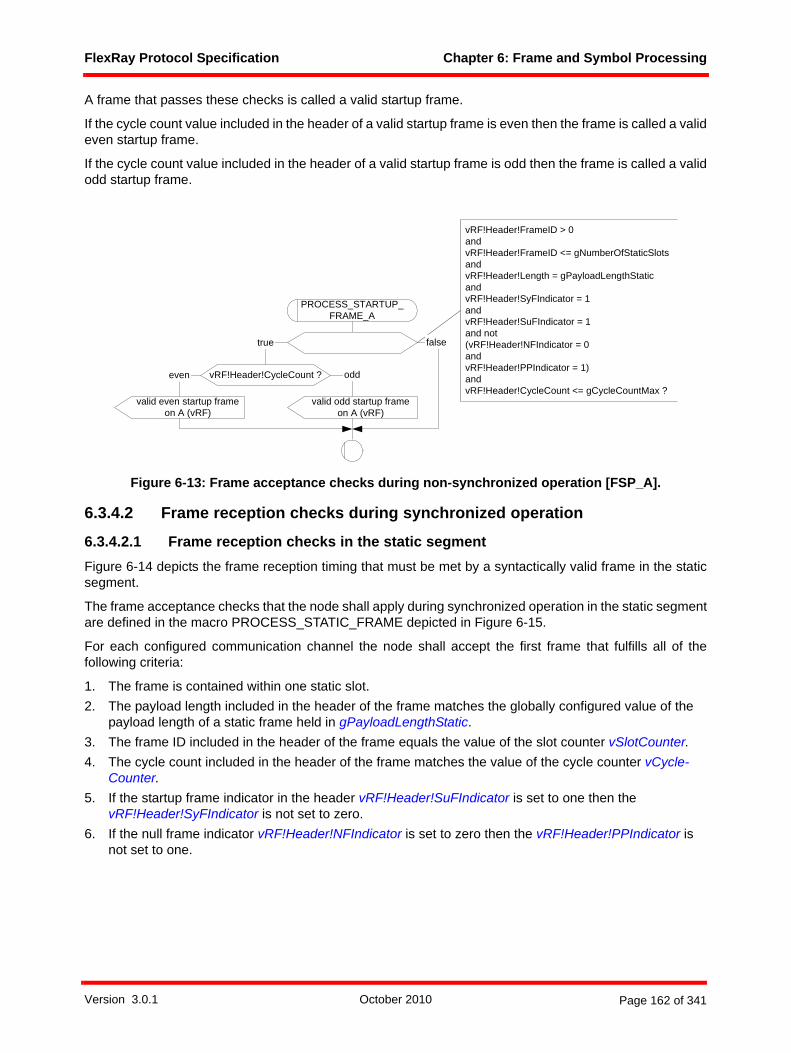
FlexRay Protocol Specification Chapter 6: Frame and Symbol Processing
A frame that passes these checks is called a valid startup frame.
If the cycle count value included in the header of a valid startup frame is even then the frame is called a valideven startup frame.
If the cycle count value included in the header of a valid startup frame is odd then the frame is called a validodd startup frame.
Figure 6-13: Frame acceptance checks during non-synchronized operation [FSP_A].
6.3.4.2 Frame reception checks during synchronized operation
6.3.4.2.1 Frame reception checks in the static segmentFigure 6-14 depicts the frame reception timing that must be met by a syntactically valid frame in the staticsegment.
The frame acceptance checks that the node shall apply during synchronized operation in the static segmentare defined in the macro PROCESS_STATIC_FRAME depicted in Figure 6-15.
For each configured communication channel the node shall accept the first frame that fulfills all of thefollowing criteria:
1. The frame is contained within one static slot.2. The payload length included in the header of the frame matches the globally configured value of the
payload length of a static frame held in gPayloadLengthStatic.3. The frame ID included in the header of the frame equals the value of the slot counter vSlotCounter.4. The cycle count included in the header of the frame matches the value of the cycle counter vCycle-
Counter.5. If the startup frame indicator in the header vRF!Header!SuFIndicator is set to one then the
vRF!Header!SyFIndicator is not set to zero.6. If the null frame indicator vRF!Header!NFIndicator is set to zero then the vRF!Header!PPIndicator is
not set to one.
vRF!Header!FrameID > 0andvRF!Header!FrameID <= gNumberOfStaticSlotsandvRF!Header!Length = gPayloadLengthStaticandvRF!Header!SyFIndicator = 1andvRF!Header!SuFIndicator = 1and not(vRF!Header!NFIndicator = 0andvRF!Header!PPIndicator = 1)andvRF!Header!CycleCount <= gCycleCountMax ?
false
vRF!Header!CycleCount ?
true
oddeven
PROCESS_STARTUP_FRAME_A
valid odd startup frameon A (vRF)
valid even startup frameon A (vRF)
Version 3.0.1 October 2010 Page 162 of 341

FlexRay Protocol Specification Chapter 6: Frame and Symbol Processing
Figure 6-14: Frame reception timing for a static slot.
Figure 6-15: Frame acceptance checks for the static segment [FSP_A].
6.3.4.2.2 Frame reception checks in the dynamic segmentFigure 6-16 depicts the frame reception timing that must be met by a syntactically valid frame in the dynamicsegment.
The frame acceptance checks that the node shall apply during synchronized operation in the dynamicsegment are defined in the macro PROCESS_DYNAMIC_FRAME depicted in Figure 6-17.
For each configured communication channel the node shall accept the first frame that fulfills all of thefollowing criteria:
1. The frame ID included in the header of the frame is greater than 0 and matches the value of the slot counter vSlotCounter.
2. The cycle count included in the header of the frame matches the value of the cycle counter vCycle-Counter.
3. The sync frame indicator included in the header is set to zero. 4. The startup frame indicator included in the header is set to zero.5. The null frame indicator included in the header is set to one.
macrotick
channel idledelimiterchannel active channel idlechannel idle
start of frame with ID x must occur within static slot x
('CE start on A/B')
channel idle recognition point('CHIRP on A/B')
static slot
vRF!Header!Length = gPayloadLengthStaticandvRF!Header!FrameID = vSlotCounterandvRF!Header!CycleCount = vCycleCounterand not(vRF!Header!SuFIndicator = 1and vRF!Header!SyFIndicator = 0)and not(vRF!Header!NFIndicator = 0andvRF!Header!PPIndicator = 1) ?
PROCESS_STATIC_FRAME_A
vSS!ContentError := true;vSS!ValidFrame := true;
true false
content error on A
Version 3.0.1 October 2010 Page 163 of 341
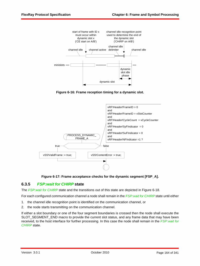
FlexRay Protocol Specification Chapter 6: Frame and Symbol Processing
Figure 6-16: Frame reception timing for a dynamic slot.
Figure 6-17: Frame acceptance checks for the dynamic segment [FSP_A].
6.3.5 FSP:wait for CHIRP state The FSP:wait for CHIRP state and the transitions out of this state are depicted in Figure 6-18.
For each configured communication channel a node shall remain in the FSP:wait for CHIRP state until either
1. the channel idle recognition point is identified on the communication channel, or2. the node starts transmitting on the communication channel.
If either a slot boundary or one of the four segment boundaries is crossed then the node shall execute theSLOT_SEGMENT_END macro to provide the current slot status, and any frame data that may have beenreceived, to the host interface for further processing. In this case the node shall remain in the FSP:wait forCHIRP state.
dynamic slot
dynamicslot idlephase
channel idle delimiter channel idlechannel activechannel idle
start of frame with ID xmust occur within
dynamic slot x('CE start on A/B')
channel idle recognition point used to determine the end of
the dynamic slot('CHIRP on A/B')
minislots
vRF!Header!FrameID > 0andvRF!Header!FrameID = vSlotCounterandvRF!Header!CycleCount = vCycleCounterandvRF!Header!SyFIndicator = 0andvRF!Header!SuFIndicator = 0andvRF!Header!NFIndicator =1 ?
PROCESS_DYNAMIC_FRAME_A
vSS!ContentError := true;vSS!ValidFrame := true;
true false
Version 3.0.1 October 2010 Page 164 of 341

FlexRay Protocol Specification Chapter 6: Frame and Symbol Processing
Figure 6-18: Transitions from the FSP:wait for CHIRP state [FSP_A].
6.3.6 FSP:wait for transmission end stateThe FSP:wait for transmission end state and the transitions out of this state are depicted in Figure 6-19.
For each configured communication channel a node shall remain in the FSP:wait for transmission end stateuntil either
1. the transmission ends on the channel, or2. the slot boundary or one of the four segment boundaries is crossed.
If either a slot boundary or one of the four segment boundaries is crossed then the node shall signal a fatalprotocol error to the protocol operation control process.
wait for CHIRP
dynamic segment start on A (vSlotCounter)
symbol window start on A (vSlotCounter)
NIT start on A(vSlotCounter)
CHIRP on A
wait for CE start
wait for transmission end
vSS!SyntaxError := true;vSS!TxConflict := true;
wait for CHIRP
zSegment := DYNAMIC; zSegment := SW; zSegment := NIT;
vSS!BViolation:= true;
static segment start on A (vCycleCounter, vSlotCounter)
slot boundary on A (vSlotCounter)
zSegment := STATIC;
SLOT_SEGMENT_END_A
decoding halted on A
vSS!SyntaxError := true;
decoding error on A ()
wait for CHIRP
Version 3.0.1 October 2010 Page 165 of 341
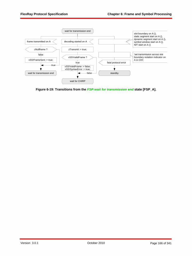
FlexRay Protocol Specification Chapter 6: Frame and Symbol Processing
Figure 6-19: Transitions from the FSP:wait for transmission end state [FSP_A].
wait for transmission end
decoding started on A
fatal protocol error
wait for CHIRP
standby
slot boundary on A (),static segment start on A (),dynamic segment start on A (),symbol window start on A (),NIT start on A ()
’set transmission across slot boundary violation indicator on A in CHI’;
frame transmitted on A
zNullframe ?
wait for transmission end
vSS!FrameSent := true;
false
true vSS!ValidFrame := false;vSS!SyntaxError := true;
vSS!ValidFrame ?
true
false
zTransmit := true;
Version 3.0.1 October 2010 Page 166 of 341

FlexRay Protocol Specification Chapter 7: Wakeup and Startup
Chapter 7Wakeup and Startup
This chapter describes the protocol mechanisms available to allow a node to cause a transition of a FlexRaycluster from a sleep mode to a mode where nodes are ready to begin synchronized operation (wakeup) andto allow a node to either initiate synchronized operation or integrate into a cluster that is already operating(startup).
First the protocol aspects of cluster wakeup are described in detail. Additional material in the form of appli-cation notes related to the interaction between the communication controller and host, as well as describingtechniques for wakeup during operation, may be found in Appendix C.
Following the wakeup section, communication startup is described. This section also describes theintegration (or reintegration) of nodes into a communication cluster.
7.1 Cluster wakeupThis section describes the procedure83 used by communication controllers to initiate the remote clusterwakeup. The following procedures assume that the bus drivers in the system support the optional remotewakeup detection capability.
7.1.1 PrinciplesThe minimum prerequisite for a cluster wakeup is that the receivers of all bus drivers be supplied with power.A bus driver has the ability to wake up the other components of its node when it receives a wakeup patternon its channel. At least one node in the cluster needs an external wakeup source.
The host completely controls the wakeup procedure84. The communication controller provides the host theability to transmit a special wakeup pattern (see Chapter 3) on each of its available channels separately.The wakeup pattern must not be transmitted on both channels at the same time. This is done to prevent afaulty node from disturbing communication on both channels simultaneously with the transmission. The hostmust configure which channel the communication controller shall wake up. The communication controllerensures that ongoing communication on this channel is not disturbed.
The wakeup pattern then causes any fault-free receiving node to wake up if it is still asleep. Generally, thebus driver of the receiving node recognizes the wakeup pattern and triggers the node wakeup. The commu-nication controller needs to recognize the wakeup pattern only during the wakeup (for collision resolution)and startup phases.
The communication controller cannot verify whether all nodes connected to the configured channel areawake after the transmission of the wakeup pattern85 since these nodes cannot give feedback until thestartup phase. The host shall be aware of possible failures of the wakeup and act accordingly.
83 To simplify discussion, the sequence of tasks executed while triggering the cluster wakeup is referred to here as the wakeup "procedure" even though it is realized as an SDL macro, and not an SDL procedure. The normal grammatical use of the term is intended rather than the precise SDL definition. Since SDL processes are not used in the wakeup mechanism, the usage does not introduce ambiguity.
84 The host may force a mode change from wakeup mode to the POC:ready state. Note, however, that a forced mode-change to the POC:ready state during wakeup may have consequences regarding the consistency of the cluster.
85 For example, the transmission unit of the bus driver may be faulty.
Version 3.0.1 October 2010 Page 167 of 341

FlexRay Protocol Specification Chapter 7: Wakeup and Startup
The wakeup procedure supports the ability for single-channel devices in a dual-channel system to initiatecluster wakeup by transmitting the wakeup pattern on the single channel to which they are connected.Another node, which has access to both channels, then assumes the responsibility for waking up the otherchannel and transmits a wakeup pattern on it (see Appendix C).
The wakeup procedure tolerates any number of nodes simultaneously trying to wake up a channel andresolves this situation such that eventually only one node transmits the wakeup pattern. Additionally, thewakeup pattern is collision resilient; so even in the presence of a fault causing two nodes to simultaneouslytransmit a wakeup pattern the signal resulting from the collision can still wake up the other nodes.
7.1.2 DescriptionThe wakeup procedure is a subset of the Protocol Operation Control (POC) process. The relationshipbetween the POC and the other protocol processes is depicted in Figure 7-186.
86 The dark lines represent data flows between mechanisms that are relevant to this chapter. The lighter gray lines are relevant to the protocol, but not to this chapter.
Version 3.0.1 October 2010 Page 168 of 341

FlexRay Protocol Specification Chapter 7: Wakeup and Startup
Figure 7-1: Protocol operation control context.
7.1.3 Wakeup support by the communication controllerThe host must initialize the wakeup of the FlexRay cluster. The host has to configure the wakeup channelpWakeupChannel while the communication controller is in the POC:config state.
The host commands its communication controller to send a wakeup pattern on channel pWakeupChannelwhile the communication controller is in the POC:ready state. The communication controller then leaves thePOC:ready state, begins the wakeup procedure (see Figure 7-2) and tries to transmit a wakeup pattern onthe configured channel. Upon completion of the procedure it signals back the status of the wakeup attemptto the host (see section 9.3.1.3.1).
The host must properly configure the communication controller before it may trigger the cluster wakeup.
In the SDL description the wakeup procedure is realized as a macro that is called by the protocol operationcontrol state machine (see Chapter 2).
frame and symbolprocessing
media accesscontrol
clocksynchronization
startup
macrotickgeneration
clocksynchronization
processing
protocoloperation
control
controllerhost interface
coding / decodingprocesseschannel A
frame and symbolprocessingchannel A
media accesscontrol
channel A
clocksynchronization
startup channel A
to channel interface from channel interface
to / from host
mediaaccesscontrolchannel B
coding / decodingprocesseschannel B
frame andsymbolprocessingchannel B
clocksynchronization
startupchannel B
Version 3.0.1 October 2010 Page 169 of 341
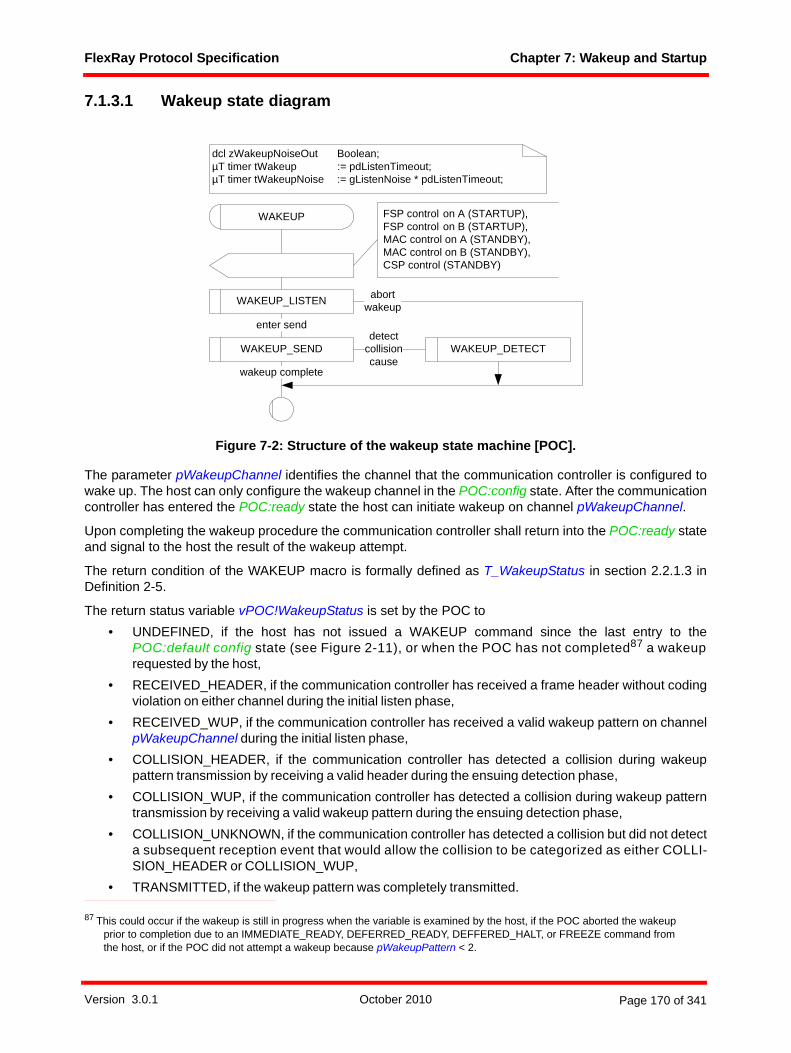
FlexRay Protocol Specification Chapter 7: Wakeup and Startup
7.1.3.1 Wakeup state diagram
Figure 7-2: Structure of the wakeup state machine [POC].
The parameter pWakeupChannel identifies the channel that the communication controller is configured towake up. The host can only configure the wakeup channel in the POC:config state. After the communicationcontroller has entered the POC:ready state the host can initiate wakeup on channel pWakeupChannel.
Upon completing the wakeup procedure the communication controller shall return into the POC:ready stateand signal to the host the result of the wakeup attempt.
The return condition of the WAKEUP macro is formally defined as T_WakeupStatus in section 2.2.1.3 inDefinition 2-5.
The return status variable vPOC!WakeupStatus is set by the POC to• UNDEFINED, if the host has not issued a WAKEUP command since the last entry to the
POC:default config state (see Figure 2-11), or when the POC has not completed87 a wakeuprequested by the host,
• RECEIVED_HEADER, if the communication controller has received a frame header without codingviolation on either channel during the initial listen phase,
• RECEIVED_WUP, if the communication controller has received a valid wakeup pattern on channelpWakeupChannel during the initial listen phase,
• COLLISION_HEADER, if the communication controller has detected a collision during wakeuppattern transmission by receiving a valid header during the ensuing detection phase,
• COLLISION_WUP, if the communication controller has detected a collision during wakeup patterntransmission by receiving a valid wakeup pattern during the ensuing detection phase,
• COLLISION_UNKNOWN, if the communication controller has detected a collision but did not detecta subsequent reception event that would allow the collision to be categorized as either COLLI-SION_HEADER or COLLISION_WUP,
• TRANSMITTED, if the wakeup pattern was completely transmitted.
87 This could occur if the wakeup is still in progress when the variable is examined by the host, if the POC aborted the wakeup prior to completion due to an IMMEDIATE_READY, DEFERRED_READY, DEFFERED_HALT, or FREEZE command from the host, or if the POC did not attempt a wakeup because pWakeupPattern < 2.
dcl zWakeupNoiseOut Boolean;µT timer tWakeup := pdListenTimeout;µT timer tWakeupNoise := gListenNoise * pdListenTimeout;
WAKEUP
WAKEUP_LISTEN
enter send
abortwakeup
WAKEUP_SEND
wakeup complete
detectcollisioncause
FSP control on A (STARTUP),FSP control on B (STARTUP),MAC control on A (STANDBY),MAC control on B (STANDBY),CSP control (STANDBY)
WAKEUP_DETECT
Version 3.0.1 October 2010 Page 170 of 341
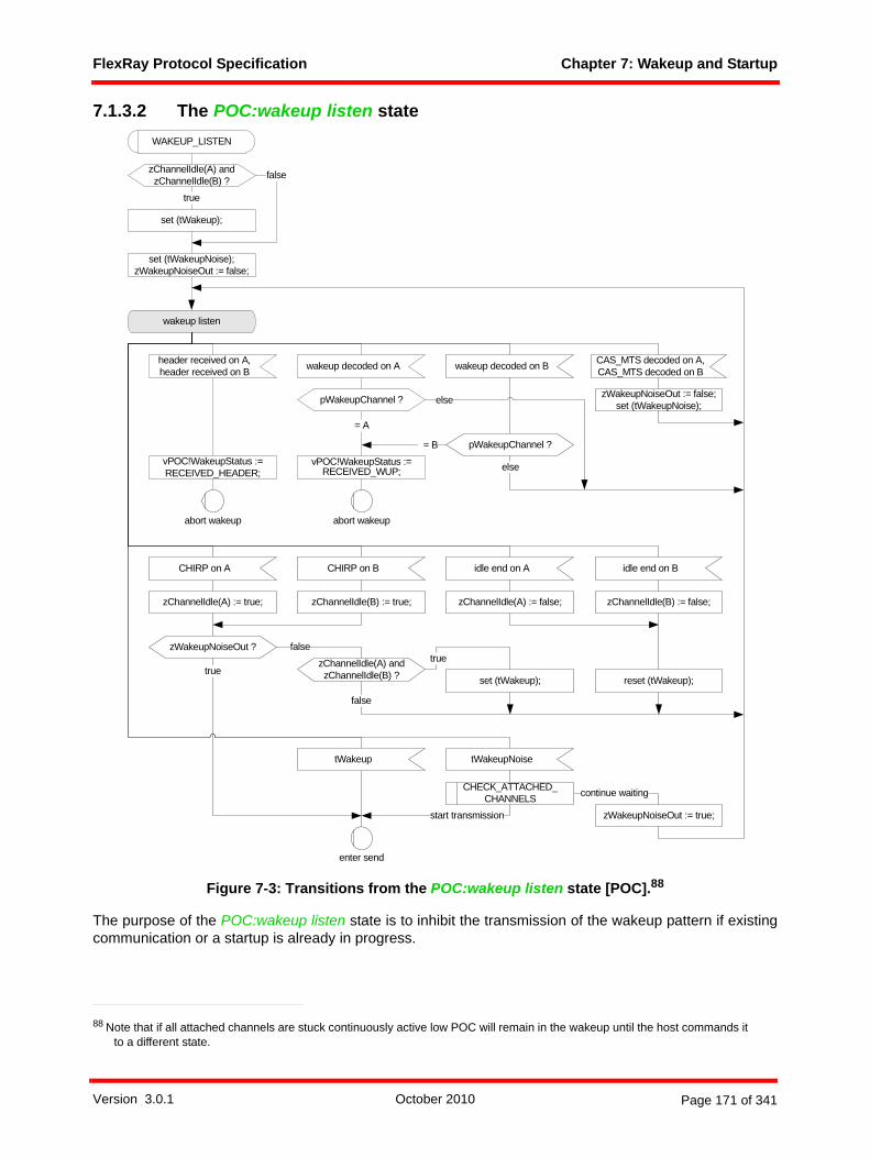
FlexRay Protocol Specification Chapter 7: Wakeup and Startup
7.1.3.2 The POC:wakeup listen state
Figure 7-3: Transitions from the POC:wakeup listen state [POC].88
The purpose of the POC:wakeup listen state is to inhibit the transmission of the wakeup pattern if existingcommunication or a startup is already in progress.
88 Note that if all attached channels are stuck continuously active low POC will remain in the wakeup until the host commands it to a different state.
set (tWakeupNoise);zWakeupNoiseOut := false;
wakeup listen
start transmission
false
tWakeupNoise
WAKEUP_LISTEN
abort wakeup
tWakeup
enter send
reset (tWakeup);set (tWakeup);
true
CHIRP on A idle end on ACHIRP on B idle end on B
zChannelIdle(A) := true; zChannelIdle(A) := false;zChannelIdle(B) := true; zChannelIdle(B) := false;
zChannelIdle(A) and zChannelIdle(B) ?
zChannelIdle(A) and zChannelIdle(B) ? false
set (tWakeup);
true
vPOC!WakeupStatus := RECEIVED_HEADER;
header received on A,header received on B
abort wakeup
zWakeupNoiseOut := false;set (tWakeupNoise);
CAS_MTS decoded on A,CAS_MTS decoded on B
vPOC!WakeupStatus := RECEIVED_WUP;
wakeup decoded on A wakeup decoded on B
= B
= A
zWakeupNoiseOut ?
zWakeupNoiseOut := true;
continue waiting
true
pWakeupChannel ?
pWakeupChannel ?
else
else
CHECK_ATTACHED_CHANNELS
false
Version 3.0.1 October 2010 Page 171 of 341
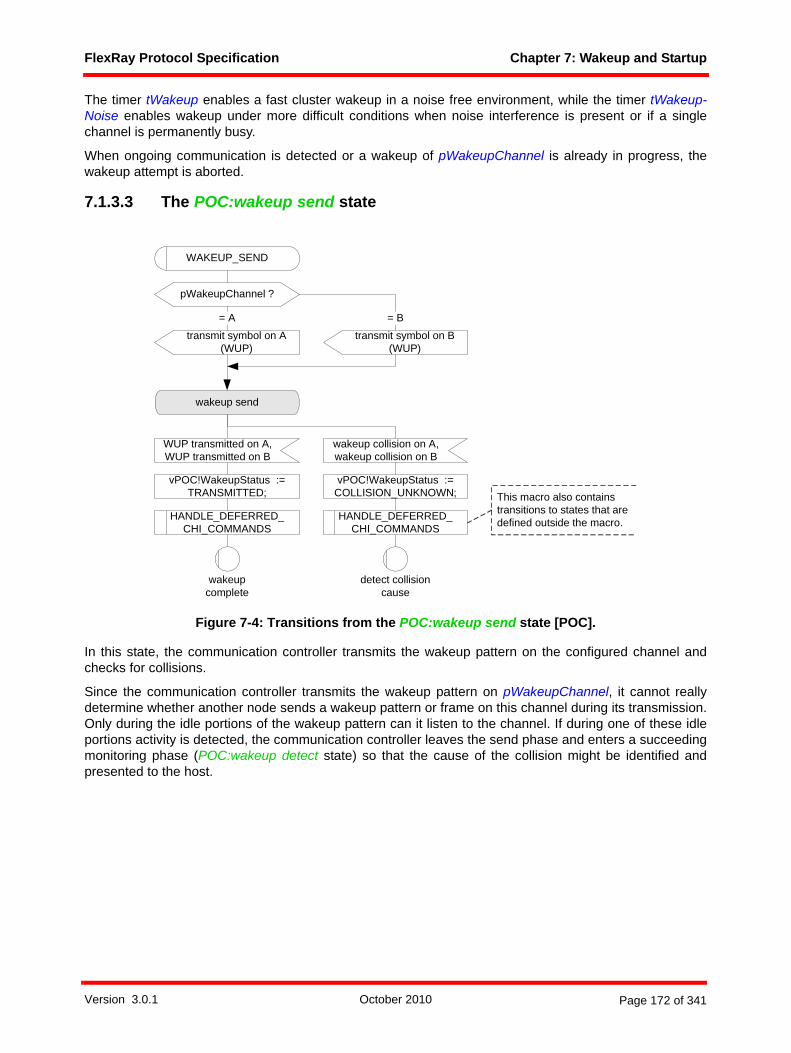
FlexRay Protocol Specification Chapter 7: Wakeup and Startup
The timer tWakeup enables a fast cluster wakeup in a noise free environment, while the timer tWakeup-Noise enables wakeup under more difficult conditions when noise interference is present or if a singlechannel is permanently busy.
When ongoing communication is detected or a wakeup of pWakeupChannel is already in progress, thewakeup attempt is aborted.
7.1.3.3 The POC:wakeup send state
Figure 7-4: Transitions from the POC:wakeup send state [POC].
In this state, the communication controller transmits the wakeup pattern on the configured channel andchecks for collisions.
Since the communication controller transmits the wakeup pattern on pWakeupChannel, it cannot reallydetermine whether another node sends a wakeup pattern or frame on this channel during its transmission.Only during the idle portions of the wakeup pattern can it listen to the channel. If during one of these idleportions activity is detected, the communication controller leaves the send phase and enters a succeedingmonitoring phase (POC:wakeup detect state) so that the cause of the collision might be identified andpresented to the host.
wakeup send
vPOC!WakeupStatus := TRANSMITTED;
= A
WUP transmitted on A, WUP transmitted on B
transmit symbol on A (WUP)
wakeupcomplete
WAKEUP_SEND
detect collisioncause
wakeup collision on A,wakeup collision on B
pWakeupChannel ?
transmit symbol on B (WUP)
= B
HANDLE_DEFERRED_ CHI_COMMANDS
vPOC!WakeupStatus := COLLISION_UNKNOWN; This macro also contains
transitions to states that are defined outside the macro.HANDLE_DEFERRED_
CHI_COMMANDS
Version 3.0.1 October 2010 Page 172 of 341
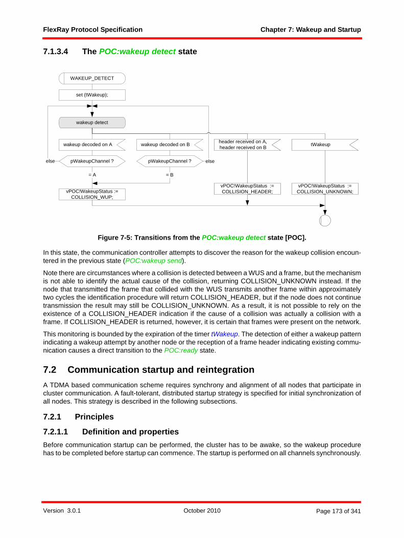
FlexRay Protocol Specification Chapter 7: Wakeup and Startup
7.1.3.4 The POC:wakeup detect state
Figure 7-5: Transitions from the POC:wakeup detect state [POC].
In this state, the communication controller attempts to discover the reason for the wakeup collision encoun-tered in the previous state (POC:wakeup send).
Note there are circumstances where a collision is detected between a WUS and a frame, but the mechanismis not able to identify the actual cause of the collision, returning COLLISION_UNKNOWN instead. If thenode that transmitted the frame that collided with the WUS transmits another frame within approximatelytwo cycles the identification procedure will return COLLISION_HEADER, but if the node does not continuetransmission the result may still be COLLISION_UNKNOWN. As a result, it is not possible to rely on theexistence of a COLLISION_HEADER indication if the cause of a collision was actually a collision with aframe. If COLLISION_HEADER is returned, however, it is certain that frames were present on the network.
This monitoring is bounded by the expiration of the timer tWakeup. The detection of either a wakeup patternindicating a wakeup attempt by another node or the reception of a frame header indicating existing commu-nication causes a direct transition to the POC:ready state.
7.2 Communication startup and reintegrationA TDMA based communication scheme requires synchrony and alignment of all nodes that participate incluster communication. A fault-tolerant, distributed startup strategy is specified for initial synchronization ofall nodes. This strategy is described in the following subsections.
7.2.1 Principles
7.2.1.1 Definition and propertiesBefore communication startup can be performed, the cluster has to be awake, so the wakeup procedurehas to be completed before startup can commence. The startup is performed on all channels synchronously.
wakeup detect
vPOC!WakeupStatus := COLLISION_WUP;
vPOC!WakeupStatus := COLLISION_HEADER;
set (tWakeup);
header received on A,header received on B
WAKEUP_DETECT
tWakeup
vPOC!WakeupStatus := COLLISION_UNKNOWN;
wakeup decoded on A
= A
wakeup decoded on B
= B
pWakeupChannel ? pWakeupChannel ?else else
Version 3.0.1 October 2010 Page 173 of 341

FlexRay Protocol Specification Chapter 7: Wakeup and Startup
The action of initiating a startup process is called a coldstart. Only a limited number of nodes may initiate astartup, they are called the coldstart nodes. The process outlined below effectively describes the startupprocedure of FlexRay clusters using any synchronization method. As the TT-E synchronization methoduses a drastically simplified startup process, much of the description is not relevant for TT-E coldstart nodesas indicated in the textual and SDL description.
With the exception of TT-E clusters a coldstart attempt begins with the transmission of a collision avoidancesymbol (CAS). Only the coldstart node that transmits the CAS transmits frames in the first four cycles afterthe CAS. It is then joined first by the other coldstart nodes (if present) and afterwards by all other nodes.
A coldstart node has the configuration parameter pKeySlotUsedForStartup set to true and is configured witha frame header containing a startup frame indicator set to one (see Chapter 4). At least two fault-freecoldstart nodes are necessary for the cluster to start up. In TT-D clusters consisting of two nodes, each nodeshall be a coldstart node. Each startup frame shall also be a sync frame; therefore each coldstart node willalso be a sync node. In order to accommodate the possibility of the failure of a coldstart node, a TT-D clusterconsisting of three or more nodes should configure at least three nodes as coldstart nodes.89
A coldstart node that actively starts the cluster is also called a leading coldstart node. A coldstart node thatintegrates upon another coldstart node is also called a following coldstart node. By definition a TT-Lcoldstart node can never be a following coldstart node, as it is the sole coldstart node of its cluster. As TT-E coldstart nodes essentially skip the usual startup process, the distinction is meaningless for them.
A node is in "startup" if its protocol operation control machine is in one of the states contained in theSTARTUP macro (vPOC!State is set to STARTUP during this time, see Figure 2-12). During startup, a nodemay only transmit startup frames. Any coldstart node shall wake up the cluster or determine that it is alreadyawake before entering startup (see section C.1).
7.2.1.2 Principle of operationThe system startup consists of two logical steps. In the first step dedicated coldstart nodes start up. In thesecond step the other nodes integrate to the coldstart nodes.
7.2.1.2.1 Startup performed by the coldstart nodes• Only the coldstart nodes can initiate the cluster start up. • When the TT-D synchronization method is used by the cluster, each of the TT-D coldstart nodes
finishes its startup as soon as stable communication with one of the other coldstart nodes is estab-lished. A TT-L coldstart node always finishes the startup after six cycles. A TT-E coldstart nodefinishes its startup as soon as it receives the first cycle start from its time gateway source node afterhaving previously received information about rate and offset correction terms and confirmation thatthe time gateway source node is in POC:normal active.
7.2.1.2.2 Integration of the non-coldstart nodes• A non-coldstart node requires at least two startup frames with different frame IDs for integration.In a
TT-D cluster this condition ensures that each non-coldstart node always joins the majority of thecoldstart nodes90.
• Integrating non-coldstart nodes may start their integration before coldstart nodes have finished theirstartup.
• Integrating non-coldstart nodes in a TT-D cluster will not finish their startup until at least twocoldstart nodes have finished their startup.
89 This does not imply any restrictions concerning which nodes may initiate a cluster wakeup.90 This is the case under the assumption that the cluster contains exactly the three recommended coldstart nodes.
Version 3.0.1 October 2010 Page 174 of 341

FlexRay Protocol Specification Chapter 7: Wakeup and Startup
7.2.2 DescriptionThe startup procedure is a subset of the Protocol Operation Control (POC) process. The relationshipbetween the POC and the other protocol processes is depicted in Figure 7-6.
Figure 7-6: Protocol operation control context.
7.2.3 Coldstart inhibit modeIn coldstart inhibit mode the communication controller is prevented from initializing the TDMA communi-cation schedule. The communication controller is automatically set into coldstart inhibit mode prior toentering the POC:ready state. The CC remains in this mode until the host commands the node to leavecoldstart inhibit mode by means of an ALLOW_COLDSTART command issued after the POC enters thePOC:ready state91.
91 Note there is no mechanism that allows the host to explicitly place the node into coldstart inhibit mode - this happens automatically as part of the process of reaching POC:ready.
frame and symbolprocessing
media accesscontrol
clock synchronization
startup
macrotickgeneration
clock synchronization
processing
protocoloperation
control
controllerhost interface
coding / decoding processeschannel A
frame and symbolprocessingchannel A
media accesscontrol
channel A
clock synchronization
startup channel A
to channel interface from channel interface
to / from host
media accesscontrolchannel B
coding / decodingprocesseschannel B
frame and symbolprocessingchannel B
clock synchronization
startup channel B
Version 3.0.1 October 2010 Page 175 of 341

FlexRay Protocol Specification Chapter 7: Wakeup and Startup
While in coldstart inhibit mode, the communication controller is not allowed to assume the role of a leadingcoldstart node, i.e., entering the coldstart path is prohibited. The node is still allowed to integrate into arunning cluster or to act as a following coldstart node, transmitting startup frames after another coldstartnode has started the initialization of cluster communication. Once the node is synchronized and integratedinto cluster communication, the coldstart inhibit mode does not restrict the node's ability to transmit frames.
The coldstart inhibit status of a node is represented by the vColdstartInhibit variable, with a value of trueindicating the node is in coldstart inhibit mode and a value of false indicating the node is not in coldstartinhibit mode.
The coldstart inhibit mode can be used either to completely prohibit active startup attempts of a node (if thehost never issues an ALLOW_COLDSTART command), or only delay them (if the host issues the CHIcommand during a startup procedure). As a result, the coldstart inhibit mode may be used to attempt toensure that all fault-free coldstart nodes are ready for startup and in the POC:coldstart listen state beforeone of them initiates a coldstart attempt.
Note that a coldstart node in a TT-E cluster (i.e., a node with pExternalSync set to true) will never be incoldstart inhibit mode as it follows a fundamentally different path for startup. Such nodes will operate as acoldstart node even without the issuance of an ALLOW_COLDSTART command.
7.2.4 Startup state diagramThere are several ways that a node can enter communication. Section 7.2.4.1 describes the path followedby the leading coldstarter in a TT-D or TT-L cluster. Section 7.2.4.2 describes the paths available to a TT-Dcoldstart node that does not act as the leading coldstarter. Section 7.2.4.4 describes the path followed by aTT-E coldstart node. Section 7.2.4.5 describes the path of a non-coldstart node in all cluster types. All ofthese sections provide only an overview92 of the operation - the precise behavior is defined by the SDLdescriptions in the subsequent sections.
92 Note that there are a large number of paths possible involving multiple executions of the STARTUP_PREPARE macro (for example, paths involving one or more aborted startup attempts). No overview of these paths is provided, but their behavior is explicitly defined by the SDL descriptions in this chapter.
Version 3.0.1 October 2010 Page 176 of 341

FlexRay Protocol Specification Chapter 7: Wakeup and Startup
Figure 7-7: Startup state diagram [POC].
dcl zTwoSNRequired Boolean;dcl zStartupNoiseOut Boolean;dcl zColdstartNoise Boolean;dcl zColdstartAborted Boolean;dcl zCycleTemp T_CycleCounter;dcl zIntegrating T_ChannelBoolArray;dcl zTwoSNSeen Integer;dcl vRemainingColdstartAttempts Integer;
µT timer tStartup := pdListenTimeout;µT timer tStartupNoise := gListenNoise *
pdListenTimeout;
enter startupprepare
vRemainingColdstartAttempts := gColdstartAttempts;’update vRemainingColdstartAttempts in CHI’;
STARTUP
INTEGRATION_LISTENCOLDSTART_LISTEN
enter coldstartcollision resolution enter
initialize schedule
COLDSTART_COL-LISION_RESOLUTION
enterinitialize schedule
abortstartup
enter coldstartconsistency check
COLDSTART_CON-SISTENCY_CHECK
abortstartupenter
coldstart gapenter
operation
enter integrationconsistency check
enter startupprepare
INTEGRATION_CON-SISTENCY_CHECK
enteroperation
STARTUP_PREPARE
entercoldstart listen
enterintegration listen
COLDSTART_GAPabort
startupenter coldstartcollision resolution
ABORT_STARTUP
abortstartup
INITIALIZE_SCHEDULE
INTEGRATION_COLD-START_CHECK
COLDSTART_JOIN
enteroperation
abortstartup
enter integrationcoldstart check
entercoldstart join
abortstartup
EXTERNAL_STARTUPenter
externalstartup
TT-E time gateway sink behavior (optional)
Version 3.0.1 October 2010 Page 177 of 341
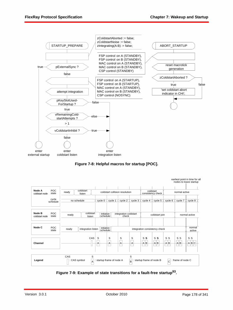
FlexRay Protocol Specification Chapter 7: Wakeup and Startup
Figure 7-8: Helpful macros for startup [POC].
Figure 7-9: Example of state transitions for a fault-free startup93.
vRemainingCold-startAttempts ?
vColdstartInhibit ?
> 1
false
false
true
STARTUP_PREPARE
enterintegration listen
zColdstartAborted := false;zColdstartNoise := false;zIntegrating(A:B) := false;
pKeySlotUsed-ForStartup ?
true
else
entercoldstart listen
pExternalSync ?
false
enterexternal startup
true
attempt integration
FSP control on A (STARTUP),FSP control on B (STARTUP),MAC control on A (STANDBY),MAC control on B (STANDBY),CSP control (NOSYNC)
ABORT_STARTUP
FSP control on A (STANDBY),FSP control on B (STANDBY),MAC control on A (STANDBY),MAC control on B (STANDBY),CSP control (STANDBY)
reset macrotick generation
zColdstartAborted ?
false
'set coldstart abortindicator in CHI';
true
POC state
POC state
no schedule
A
ready coldstart listen coldstart collision resolution coldstart
consistency check normal active
ready
ready
coldstart listen
integration listen
initialize schedule
initialize schedule
integration coldstart check
integration consistency check
coldstart join
normal active
normal active
A A A A A A A AB B B B B C
Node Acoldstart node
Node Bcoldstart node
Node C
Channel
CAS
cycle 0 cycle 1 cycle 2 cycle 3 cycle 4 cycle 5 cycle 6 cycle 7 cycle 8
POC state
cycleschedule
S S S S SS SS SS S S S S
LegendCAS
: CAS symbol A
S: startup frame of node A B
S: startup frame of node B C : frame of node C
earliest point in time for allnodes to leave startup
SS
Version 3.0.1 October 2010 Page 178 of 341

FlexRay Protocol Specification Chapter 7: Wakeup and Startup
7.2.4.1 Path of a TT-D leading coldstart nodeNode A in Figure 7-9 follows this path and is therefore called a leading coldstart node.
When a coldstart node enters startup, it listens to its attached channels and attempts to receive FlexRayframes (see SDL macro COLDSTART_LISTEN in Figure 7-14).
If no communication94 is received, the node commences a coldstart attempt. The initial transmission of aCAS symbol is succeeded by the first regular cycle. This cycle has the number zero.
From cycle zero on, the node transmits its startup frame (with the exception of the coldstart gap or the abortof the startup attempt). Since each coldstart node is allowed to perform a coldstart attempt, it may occur thatseveral nodes simultaneously transmit the CAS symbol and enter the coldstart path. This situation isresolved during the first four cycles after CAS transmission. As soon as a node that initiates a coldstartattempt receives a CAS symbol or a frame header during these four cycles, it reenters the listen state.Consequently, only one node remains in this path (see SDL macro COLDSTART_COLLISION_RESO-LUTION in Figure 7-16).
In cycle four, other coldstart nodes begin to transmit their startup frames. The node that initiated thecoldstart collects all startup frames from cycle four and five and performs the clock correction as describedin Chapter 8. If clock correction does not signal any errors and the node has received at least one validstartup frame pair, the node leaves startup and enters operation (see SDL macro COLDSTART_CON-SISTENCY_CHECK in Figure 7-17).
7.2.4.2 Path of a TT-D following coldstart nodeNode B in Figure 7-9 follows this path and is therefore called a following coldstart node.
When a coldstart node enters the startup, it listens to its attached channels and attempts to receive FlexRayframes (see SDL macro COLDSTART_LISTEN in Figure 7-14).
If communication95 is received, it tries to integrate to a transmitting coldstart node96. It tries to receive a validpair of startup frames to derive its schedule and clock correction from the coldstart node (see Chapter 8 andsee SDL macro INITIALIZE_SCHEDULE in Figure 7-19).
If these frame receptions have been successful, it collects all sync frames and performs clock correction inthe following double cycle. If clock correction does not signal any errors and if the node continues to receivesufficient frames from the same node it has integrated on, it begins to transmit its startup frame; otherwiseit reenters the listen state (see SDL macro INTEGRATION_COLDSTART_CHECK in Figure 7-20).
If for the following three cycles the clock correction does not signal any errors and at least one other coldstartnode is visible, the node leaves startup and enters operation. Thereby, it leaves startup at least one cycleafter the node that initiated the coldstart (see SDL macro COLDSTART_JOIN in Figure 7-21).
Another path, not shown in Figure 7-9, is also possible for an integrating coldstart node. If, at the time of theexecution of the STARTUP_PREPARE macro, the node is prevented from acting as a leading coldstarter(either because the vColdstartInhibit flag is set to true, or because the vRemainingColdstartAttemptsvariable indicates there are no remaining coldstart attempts) the node will instead begin to act as a normalintegrating node, waiting for a leading coldstarter to begin transmissions that will initialize the schedule (seeSDL macro INTEGRATION_LISTEN). Once such communication is detected, the node then executes theINITIALIZE_SCHEDULE macro and behaves as described earlier in this section.
93 Please note that several simplifications have been made within this diagram to make it more accessible, e.g. the state transitions do not occur on cycle change, but well before that (see Chapter 8).
94 See Figure 7-14 for exact definition.95 See Chapter 8 for exact definition.96 Presumably it is the node that initiated the coldstart, but not necessarily.
Version 3.0.1 October 2010 Page 179 of 341
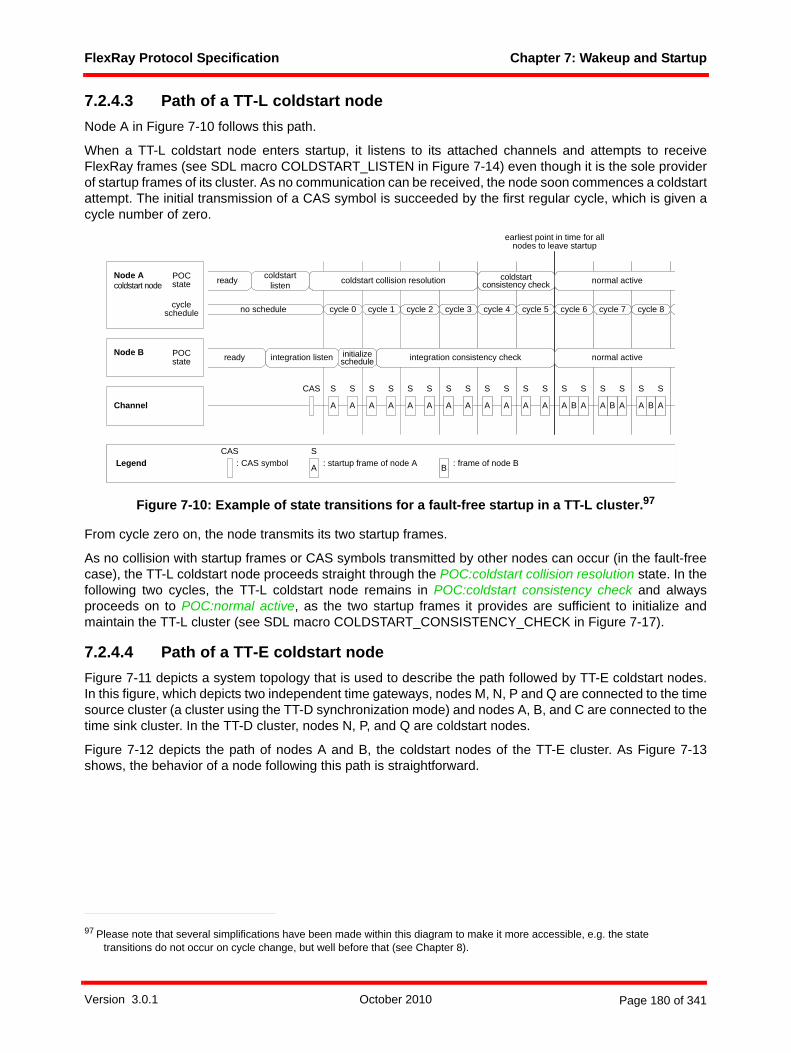
FlexRay Protocol Specification Chapter 7: Wakeup and Startup
7.2.4.3 Path of a TT-L coldstart nodeNode A in Figure 7-10 follows this path.
When a TT-L coldstart node enters startup, it listens to its attached channels and attempts to receiveFlexRay frames (see SDL macro COLDSTART_LISTEN in Figure 7-14) even though it is the sole providerof startup frames of its cluster. As no communication can be received, the node soon commences a coldstartattempt. The initial transmission of a CAS symbol is succeeded by the first regular cycle, which is given acycle number of zero.
Figure 7-10: Example of state transitions for a fault-free startup in a TT-L cluster.97
From cycle zero on, the node transmits its two startup frames.
As no collision with startup frames or CAS symbols transmitted by other nodes can occur (in the fault-freecase), the TT-L coldstart node proceeds straight through the POC:coldstart collision resolution state. In thefollowing two cycles, the TT-L coldstart node remains in POC:coldstart consistency check and alwaysproceeds on to POC:normal active, as the two startup frames it provides are sufficient to initialize andmaintain the TT-L cluster (see SDL macro COLDSTART_CONSISTENCY_CHECK in Figure 7-17).
7.2.4.4 Path of a TT-E coldstart nodeFigure 7-11 depicts a system topology that is used to describe the path followed by TT-E coldstart nodes.In this figure, which depicts two independent time gateways, nodes M, N, P and Q are connected to the timesource cluster (a cluster using the TT-D synchronization mode) and nodes A, B, and C are connected to thetime sink cluster. In the TT-D cluster, nodes N, P, and Q are coldstart nodes.
Figure 7-12 depicts the path of nodes A and B, the coldstart nodes of the TT-E cluster. As Figure 7-13shows, the behavior of a node following this path is straightforward.
97 Please note that several simplifications have been made within this diagram to make it more accessible, e.g. the state transitions do not occur on cycle change, but well before that (see Chapter 8).
POC state
no schedule
A
ready coldstart listen coldstart collision resolution coldstart
consistency check normal active
ready integration listen initialize schedule integration consistency check normal active
A A A A A A A A B
Node Acoldstart node
Node B
Channel
CAS
cycle 0 cycle 1 cycle 2 cycle 3 cycle 4 cycle 5 cycle 6 cycle 7 cycle 8
POC state
cycleschedule
S S S S S S S
LegendCAS
: CAS symbol A
S: startup frame of node A B : frame of node B
earliest point in time for allnodes to leave startup
SS
A
S
A
S
A
S
A
S
A
S
A
S
A
S
A
S
A
S
B B
Version 3.0.1 October 2010 Page 180 of 341

FlexRay Protocol Specification Chapter 7: Wakeup and Startup
Figure 7-11: Topology for the startup example of a TT-E cluster shown in Figure 7-12.
The node first starts the CSP, MAC and FSP processes and then awaits the first cycle start signal; receivingthis, the node directly continues into POC:normal active. The cycle start signal is generated as soon as the(just started) CSP process has managed to synchronize itself onto the time gateway source (see Figure 8-5).
Node C
Node Mtime gateway source node 1
Node Ntime gateway source node 2
TT-D cluster
TT-E cluster
time gateway 1 time gateway 2
Node QNode P
Node Atime gateway sink node 1
Node Btime gateway sink node 2
coldstart node
non-cold-start node
Legend:
Version 3.0.1 October 2010 Page 181 of 341

FlexRay Protocol Specification Chapter 7: Wakeup and Startup
Figure 7-12: Example of state transitions for a fault-free startup in a TT-E cluster.98
Node A in Figure 7-12 enters POC:normal active very shortly after its time gateway source node (node M)has entered POC:normal active itself. The time gateway source node has provided the node A with allrelevant information about clock correction values during cycles 18 and 19, but as node M was not yet inPOC:normal active, node A could not proceed. Node A uses the cycle counter value provided by the timesource gateway node and therefore directly starts with the cycle number 20, the same cycle number thetime source cluster currently uses. The cycle schedules of Figure 7-12 have been drawn slightly offset toone another to symbolize the fixed offset of cdTSrcCycleOffset microticks between the cluster schedules.The second TT-E coldstart node, node B, also enters POC:normal active as soon as it has received allrelevant terms from its time gateway source node (node N) and does not verify its view on the scheduleagainst the already present startup frames. Node B is not required for node C to complete its startup.
98 Please note that several simplifications have been made within this diagram to make it more accessible, e.g. the state transitions do not occur on cycle change, but well before that (see Chapter 8).
ready coldstart listen normal active
ready
integration consistency check
no schedule
A
ready
external startup
normal active
ready normal active
Node Atime gateway sink node
Channeltime sink cluster
cycle 20time sink cluster cycle schedule
S S
Legend A
S: startup frame of node A B
S: startup frame of node B
cycle 21 cycle 22 cycle 23 cycle 24 cycle 25 cycle 26 cycle 27 cycle 28
external startup
A
S
A A
S S
A A
S S
A A
S S
A A
S S
A A
S
A A
S
A B A B
SSS S
A B A B
SSS
POC state normal active
Node Mtime gateway source node
cycle 20time source cluster cycle schedule cycle 21 cycle 22 cycle 23 cycle 24 cycle 25 cycle 26 cycle 27 cycle 28cycle 18 cycle 19
POC state
time gateway 1
S S
POC state
Node Ntime gateway source node
Node Btime gateway sink node
POC state
time gateway 2
integration listen
initialize schedule integration consistency check normal activeNode C POC
state
C : frame of node C
C C C
coldstart joinintegration coldstart check
initialize schedule
cdTSrcCycleOffset
Version 3.0.1 October 2010 Page 182 of 341

FlexRay Protocol Specification Chapter 7: Wakeup and Startup
Figure 7-13: External startup state [POC].
7.2.4.5 Path of a non-coldstart nodeNode C in Figure 7-9, Node B in Figure 7-10, and Node C in Figure 7-12 follow this path.
When a non-coldstart node enters startup, it listens to its attached channels and tries to receive FlexRayframes (see SDL macro INTEGRATION_LISTEN in Figure 7-22).
If communication99 is received, it tries to integrate to a transmitting coldstart node. It tries to receive a validpair of startup frames to derive its schedule and clock correction from the coldstart node (see Chapter 8 andsee SDL macro INITIALIZE_SCHEDULE in Figure 7-19).
In the following double cycles, it tries to find at least two startup frames that fit into its own schedule. In aTT-D cluster these frames will come from different coldstart nodes. If this fails, or if clock correction signalsan error, the node aborts the integration attempt and tries again.
After receiving two valid startup frame pairs with different frame IDs for two consecutive double cycles, thenode leaves startup and enters operation.
For TT-D clusters, this means that the non-coldstart node leaves startup at least two cycles later than thenode that initiated the coldstart. Effectively, all nodes of a TT-D cluster can leave startup at the end of cycle7, just before entering cycle 8 (see Figure 7-9 and SDL macro INTEGRATION_CONSISTENCY_CHECK inFigure 7-23). For TT-D and TT-E clusters, this time is reduced by one double cycle, as the two necessarystartup frames are present as much earlier (see Figure 7-10 and Figure 7-12).
99 See Chapter 8 for exact definition.
external startup
cycle start (vCycleCounter)
EXTERNAL_STARTUP
FSP control on A (GO),FSP control on B (GO),MAC control on A (KEYSLOTONLY),MAC control on B (KEYSLOTONLY),CSP control (SYNC)
TT-E time gateway sink behavior (optional)
vPOC!StartupState := EXTERNAL_STARTUP;’update vPOC in CHI’;
vPOC!SlotMode ?
KEYSLOT
else
FSP control on A (GO),FSP control on B (GO),MAC control on A (ALL),MAC control on B (ALL),CSP control (SYNC)
Version 3.0.1 October 2010 Page 183 of 341
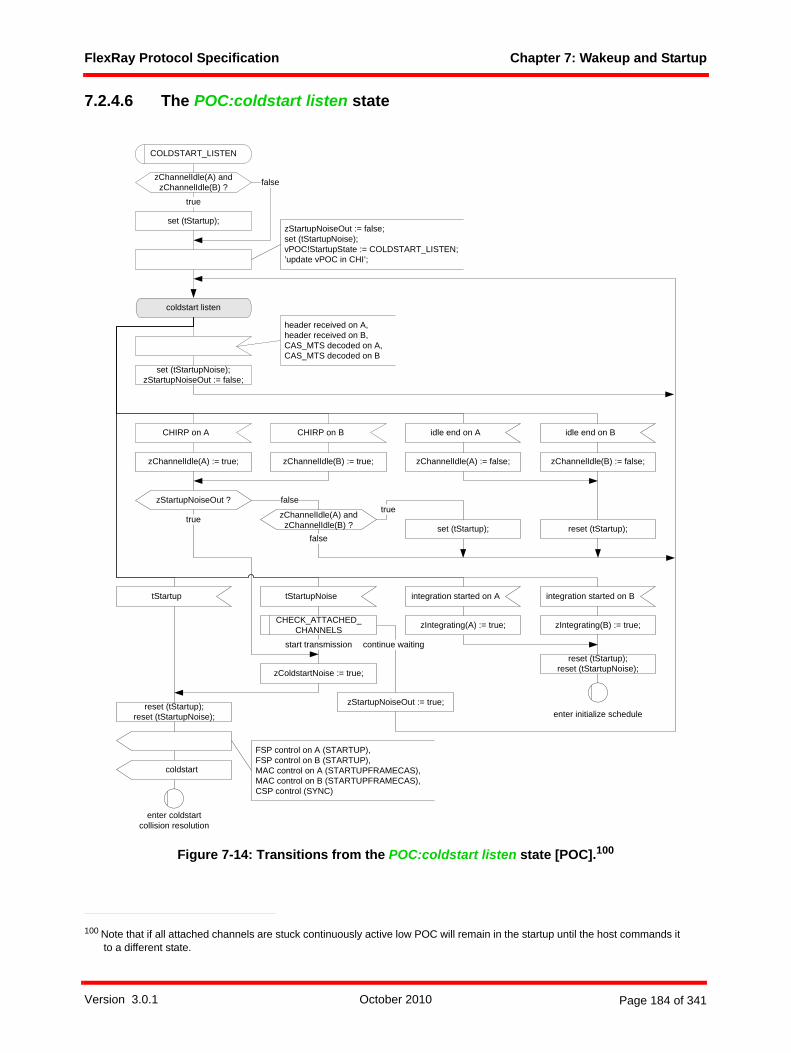
FlexRay Protocol Specification Chapter 7: Wakeup and Startup
7.2.4.6 The POC:coldstart listen state
Figure 7-14: Transitions from the POC:coldstart listen state [POC].100
100 Note that if all attached channels are stuck continuously active low POC will remain in the startup until the host commands it to a different state.
coldstart listen
set (tStartupNoise);zStartupNoiseOut := false;
reset (tStartup);set (tStartup);
true
tStartup tStartupNoise integration started on A
reset (tStartup);reset (tStartupNoise);
reset (tStartup);reset (tStartupNoise);
zChannelIdle(A) and zChannelIdle(B) ? false
set (tStartup);
true
COLDSTART_LISTEN
enter coldstartcollision resolution
enter initialize schedule
CHIRP on A idle end on ACHIRP on B idle end on B
zChannelIdle(A) := true; zChannelIdle(A) := false;zChannelIdle(B) := true; zChannelIdle(B) := false;
zChannelIdle(A) and zChannelIdle(B) ?
FSP control on A (STARTUP),FSP control on B (STARTUP),MAC control on A (STARTUPFRAMECAS),MAC control on B (STARTUPFRAMECAS),CSP control (SYNC)
integration started on B
zIntegrating(A) := true; zIntegrating(B) := true;
coldstart
zColdstartNoise := true;
start transmission
zStartupNoiseOut := false;set (tStartupNoise);vPOC!StartupState := COLDSTART_LISTEN;’update vPOC in CHI’;
zStartupNoiseOut ?
false
true
header received on A,header received on B,CAS_MTS decoded on A,CAS_MTS decoded on B
continue waiting
zStartupNoiseOut := true;
CHECK_ATTACHED_ CHANNELS
false
Version 3.0.1 October 2010 Page 184 of 341

FlexRay Protocol Specification Chapter 7: Wakeup and Startup
Figure 7-15: Macro CHECK_ATTACHED_CHANNELS [POC].
A coldstart node still allowed101 to initiate a coldstart enters the POC:coldstart listen state before actuallyperforming the coldstart. In this state the coldstart node tries to detect ongoing frame transmissions andcoldstart attempts.
This state is left and the POC:initialize schedule state is entered as soon as a valid startup frame has beenreceived (see Chapter 8 for details of this mechanism), as the node tries to integrate on the node that hastransmitted this frame.
When neither CAS symbols nor frame headers can be detected for a predetermined time duration,the nodeinitiates the coldstart and enters the POC:coldstart collision resolution state. The amount of time that has topass before a coldstart attempt may be performed is defined by the two timers tStartup and tStartupNoise.The timer tStartup expires quickly, but is stopped whenever a channel is active (see Chapter 3 for adescription of channel states). It is restarted when all attached channels are in idle state. The timer tStart-upNoise is only restarted by the reception of correctly decoded headers or CAS symbols to guarantee acluster startup when noise interference is present or if a single channel is permanently busy.
101 See macro STARTUP_PREPARE in Figure 7-8. The condition 'vRemainingColdstartAttempts > 1' arises from the necessity of using up one round through the POC:coldstart collision resolution state for the collision resolution and needing the second round for actually integrating the other nodes.
zChannelIdle(A) or zChannelIdle(B) ?
pChannels ? = A&B
zChannelIdle(A) ?
zChannelIdle(B) ? = A
= B
false
false
start transmission
continue waiting
false
true
true
true
CHECK_ATTACHED_CHANNELS
Version 3.0.1 October 2010 Page 185 of 341
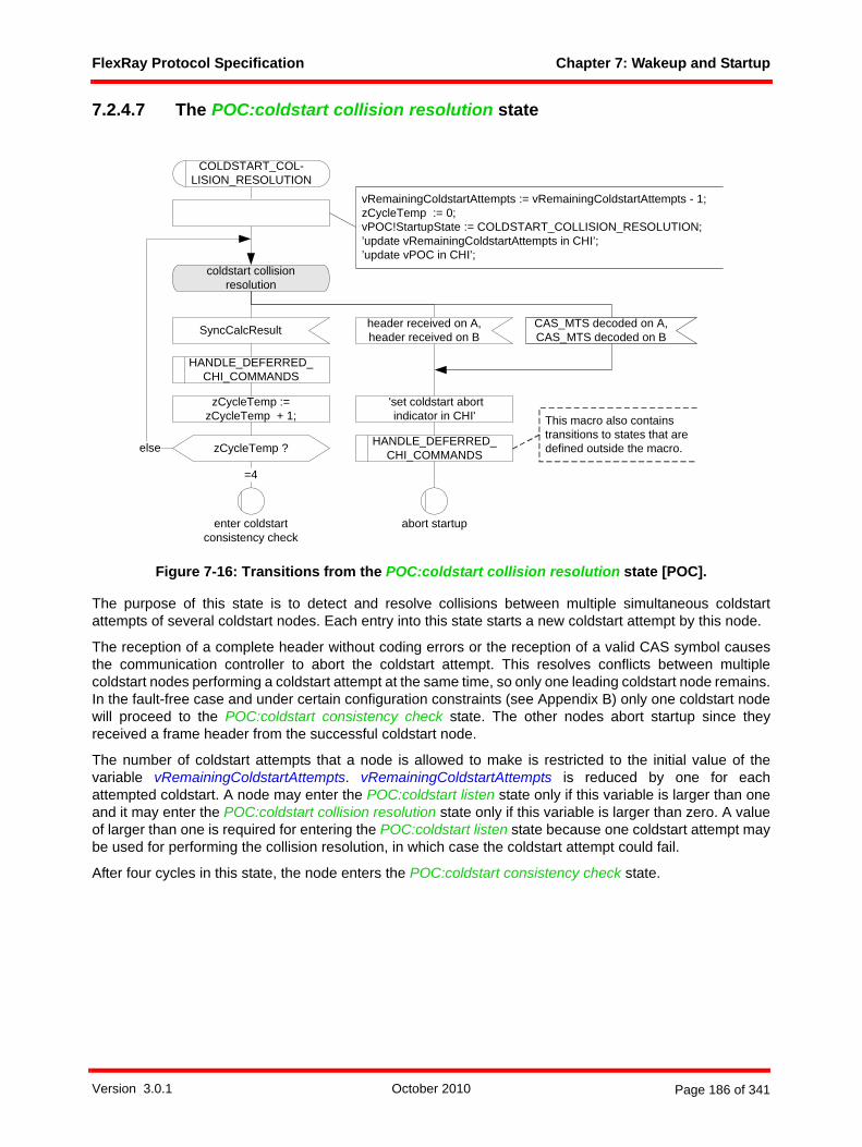
FlexRay Protocol Specification Chapter 7: Wakeup and Startup
7.2.4.7 The POC:coldstart collision resolution state
Figure 7-16: Transitions from the POC:coldstart collision resolution state [POC].
The purpose of this state is to detect and resolve collisions between multiple simultaneous coldstartattempts of several coldstart nodes. Each entry into this state starts a new coldstart attempt by this node.
The reception of a complete header without coding errors or the reception of a valid CAS symbol causesthe communication controller to abort the coldstart attempt. This resolves conflicts between multiplecoldstart nodes performing a coldstart attempt at the same time, so only one leading coldstart node remains.In the fault-free case and under certain configuration constraints (see Appendix B) only one coldstart nodewill proceed to the POC:coldstart consistency check state. The other nodes abort startup since theyreceived a frame header from the successful coldstart node.
The number of coldstart attempts that a node is allowed to make is restricted to the initial value of thevariable vRemainingColdstartAttempts. vRemainingColdstartAttempts is reduced by one for eachattempted coldstart. A node may enter the POC:coldstart listen state only if this variable is larger than oneand it may enter the POC:coldstart collision resolution state only if this variable is larger than zero. A valueof larger than one is required for entering the POC:coldstart listen state because one coldstart attempt maybe used for performing the collision resolution, in which case the coldstart attempt could fail.
After four cycles in this state, the node enters the POC:coldstart consistency check state.
coldstart collisionresolution
CAS_MTS decoded on A,CAS_MTS decoded on B
header received on A,header received on BSyncCalcResult
zCycleTemp := zCycleTemp + 1;
zCycleTemp ?else
=4
vRemainingColdstartAttempts := vRemainingColdstartAttempts - 1;zCycleTemp := 0;vPOC!StartupState := COLDSTART_COLLISION_RESOLUTION;’update vRemainingColdstartAttempts in CHI’;’update vPOC in CHI’;
COLDSTART_COL-LISION_RESOLUTION
enter coldstart consistency check
abort startup
HANDLE_DEFERRED_ CHI_COMMANDS
HANDLE_DEFERRED_ CHI_COMMANDS
'set coldstart abortindicator in CHI' This macro also contains
transitions to states that are defined outside the macro.
Version 3.0.1 October 2010 Page 186 of 341

FlexRay Protocol Specification Chapter 7: Wakeup and Startup
7.2.4.8 The POC:coldstart consistency check state
Figure 7-17: Transitions from the POC:coldstart consistency check state [POC].102
In this state, the leading coldstart node checks whether the frames transmitted by other following coldstartnodes (non-coldstart nodes cannot yet transmit in the fault-free case) fit into its schedule.
If a TT-D coldstart node receives no valid startup frames in the even cycle in this state, it is assumed thatthe other coldstart nodes were not ready soon enough to initialize their schedule from the first two startupframes sent during the POC:coldstart collision resolution state. Therefore, if another coldstart attempt isallowed, the node enters the POC:coldstart gap state to wait for the other coldstart nodes to get ready.
If a TT-D coldstart node has received a valid startup frame in the even cycle in this state, but the clockcorrection signals errors in the odd cycle or no valid pair of startup frames can be received in the doublecycle, the node aborts the coldstart attempt.
If a TT-D coldstart node has received a valid pair of startup frames and the clock correction signals no errorsthe node leaves startup and enters operation (see Chapter 2).
A TT-L coldstart node will enter operation after having remained for two cycles in this state, as it is the soleprovider of startup frames of the cluster.
102 zStartupX is zStartupNodes in even cycles and zRxStartupPairs in odd cycles. zRefX is zRefNode in even cycles and zRefPair in odd cycles. See Figure 8-6 for details.
coldstart consistency check
> 0= 0
else
odd
even
vRemainingCold-startAttempts ?
> 0
else
zStartupX ?
vCycleCounter ?
zStartupX ?
else
else
enteroperation
COLDSTART_CON-SISTENCY_CHECK
entercoldstart gap
abort startup
zColdstartAborted := true;
SyncCalcResult (zSyncCalcResult, zStartupX, zRefX)
zSyncCalcResult ?
WITHIN_BOUNDSvPOC!ColdstartNoise :=
zColdstartNoise;
vPOC!StartupState := COLDSTART_CONSISTENCY_CHECK;’update vPOC in CHI’;
HANDLE_DEFERRED_ CHI_COMMANDS
This macro also contains transitions to states that are defined outside the macro.
Version 3.0.1 October 2010 Page 187 of 341

FlexRay Protocol Specification Chapter 7: Wakeup and Startup
7.2.4.9 The POC:coldstart gap state
Figure 7-18: Transitions from the POC:coldstart gap state [POC].
In the POC:coldstart gap state the leading coldstart node stops transmitting its startup frame. This causesall nodes currently integrating on the leading coldstart node to abort their integration attempt.
In the same way as during the POC:coldstart collision resolution state, the leading coldstart node aborts thecoldstart attempt if it receives a frame header or a valid CAS symbol. If it does not receive either, it proceedsafter one cycle by reentering the POC:coldstart collision resolution state for another coldstart attempt.
coldstart gap
zColdstartAborted := true;
header received on A,header received on BSyncCalcResult
entercoldstart collision
resolutionabort startup
COLDSTART_GAP
FSP control on A (STARTUP),FSP control on B (STARTUP),MAC control on A (STARTUPFRAME),MAC control on B (STARTUPFRAME),CSP control (SYNC)
FSP control on A (STARTUP),FSP control on B (STARTUP),MAC control on A (NOCE) ,MAC control on B (NOCE),CSP control (NOSYNC)
CAS_MTS decoded on A,CAS_MTS decoded on B
vPOC!StartupState := COLDSTART_GAP;
’update vPOC in CHI’;
Version 3.0.1 October 2010 Page 188 of 341

FlexRay Protocol Specification Chapter 7: Wakeup and Startup
7.2.4.10 The POC:initialize schedule state
Figure 7-19: Transitions from the POC:initialize schedule state [POC].
As soon as a valid startup frame has been received in one of the listen states (see Figure 7-7), thePOC:initialize schedule state is entered. If clock synchronization successfully receives a matching secondvalid startup frame and derives a schedule from them (indicated by receiving the signal integrationsuccessful on A or integration successful on B), the POC goes to the POC:integration coldstart check state(for coldstart nodes) or the POC:integration consistency check state (for non-coldstart nodes).
initialize schedule
integration aborted on A
INITIALIZE_SCHEDULE
integration aborted on B
enterstartup prepare
integration started on A integration started on B
zIntegrating(B) := true;zIntegrating(A) := true;
zIntegrating(B) := false;zIntegrating(A) := false;
zIntegrating(A) or zIntegrating(B) ? true
false
false
enter integration
consistency check
integration successful on A (),integration successful on B ()
pKeySlotUsed- ForStartup ?
true
enter integration
coldstart check
vPOC!StartupState := INITIALIZE_SCHEDULE;
’update vPOC in CHI’;
Version 3.0.1 October 2010 Page 189 of 341
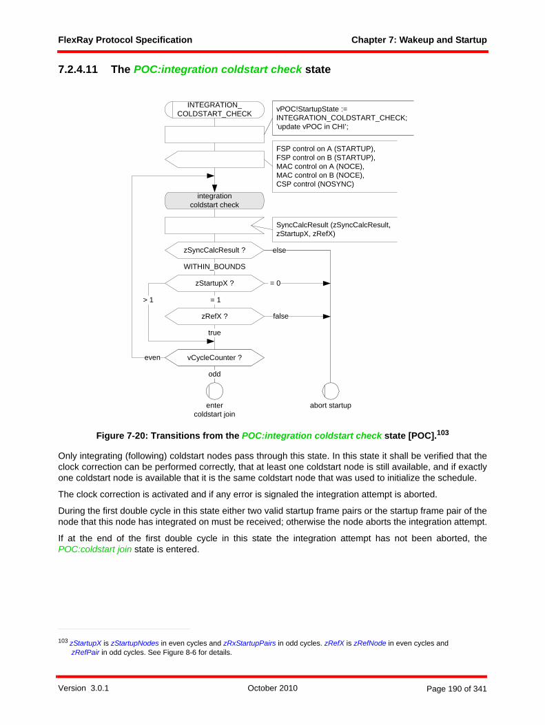
FlexRay Protocol Specification Chapter 7: Wakeup and Startup
7.2.4.11 The POC:integration coldstart check state
Figure 7-20: Transitions from the POC:integration coldstart check state [POC].103
Only integrating (following) coldstart nodes pass through this state. In this state it shall be verified that theclock correction can be performed correctly, that at least one coldstart node is still available, and if exactlyone coldstart node is available that it is the same coldstart node that was used to initialize the schedule.
The clock correction is activated and if any error is signaled the integration attempt is aborted.
During the first double cycle in this state either two valid startup frame pairs or the startup frame pair of thenode that this node has integrated on must be received; otherwise the node aborts the integration attempt.
If at the end of the first double cycle in this state the integration attempt has not been aborted, thePOC:coldstart join state is entered.
103 zStartupX is zStartupNodes in even cycles and zRxStartupPairs in odd cycles. zRefX is zRefNode in even cycles and zRefPair in odd cycles. See Figure 8-6 for details.
integrationcoldstart check
else
odd
vCycleCounter ?even
zStartupX ?
true
= 0
entercoldstart join
abort startup
INTEGRATION_ COLDSTART_CHECK
FSP control on A (STARTUP),FSP control on B (STARTUP),MAC control on A (NOCE),MAC control on B (NOCE),CSP control (NOSYNC)
zRefX ?
= 1
false
> 1
WITHIN_BOUNDS
zSyncCalcResult ?
SyncCalcResult (zSyncCalcResult,zStartupX, zRefX)
vPOC!StartupState := INTEGRATION_COLDSTART_CHECK;’update vPOC in CHI’;
Version 3.0.1 October 2010 Page 190 of 341

FlexRay Protocol Specification Chapter 7: Wakeup and Startup
7.2.4.12 The POC:coldstart join state
Figure 7-21: Transitions from the POC:coldstart join state [POC].104
Only following coldstart nodes enter this state. Upon entry they begin transmitting startup frames andcontinue to do so in subsequent cycles. Thereby, the leading coldstart node and the nodes joining it cancheck if their schedules agree with each other.
If the clock correction signals any error, the node aborts the integration attempt.
If a node in this state sees at least one valid startup frame during all even cycles in this state and at leastone valid startup frame pair during all double cycles in this state, it leaves startup and enters operation (seeChapter 2).
104 zStartupX is zStartupNodes in even cycles and zRxStartupPairs in odd cycles. zRefX is zRefNode in even cycles and zRefPair in odd cycles. See Figure 8-6 for details.
coldstart join
zCycleTemp ?else
=3
= 0zStartupX ?
> 0
zCycleTemp := zCycleTemp + 1;
else
enteroperation
COLDSTART_JOIN
abort startup
FSP control on A (STARTUP),FSP control on B (STARTUP),MAC control on A (STARTUPFRAME),MAC control on B (STARTUPFRAME),CSP control (SYNC)
WITHIN_BOUNDS
zSyncCalcResult ?
SyncCalcResult (zSyncCalcResult,zStartupX, zRefX)
zCycleTemp := 0;vPOC!StartupState := COLDSTART_JOIN;’update vPOC in CHI’;
HANDLE_DEFERRED_ CHI_COMMANDS
This macro also contains transitions to states that are defined outside the macro.
Version 3.0.1 October 2010 Page 191 of 341

FlexRay Protocol Specification Chapter 7: Wakeup and Startup
7.2.4.13 The POC:integration listen state
Figure 7-22: Transitions from the POC:integration listen state [POC].
In this state the node waits for either a valid startup frame or for the vColdstartInhibit variable to be cleared.
If the vColdstartInhibit variable is cleared the node reevaluates whether it is allowed to initiate a coldstartand consequently enter the POC:coldstart listen state.
integration listen
integration started on A
INTEGRATION_LISTEN
enterstartup prepare
enterinitializeschedule
integration started on B
zIntegrating(A) := true; zIntegrating(B) := true; vColdstartInhibit := false;
CHI ALLOW_COLDSTART command
vPOC!StartupState := INTEGRATION_LISTEN;
’update vPOC in CHI’;
Version 3.0.1 October 2010 Page 192 of 341

FlexRay Protocol Specification Chapter 7: Wakeup and Startup
7.2.4.14 The POC:integration consistency check state
Figure 7-23: Transitions from the POC:integration consistency check state [POC].105
Only integrating non-coldstart nodes pass through this state. In this state the node verifies that clockcorrection can be performed correctly and that enough coldstart nodes are sending startup frames thatagree with the node's own schedule.
105 zStartupX is zStartupNodes in even cycles and zRxStartupPairs in odd cycles. zRefX is zRefNode in even cycles and zRefPair in odd cycles. See Figure 8-6 for details.
integrationconsistency check
else
odd
vCycleCounter ?even
enteroperation
zTwoSNSeen := 0;zTwoSNRequired := false;vPOC!StartupState := INTEGRATION_CONSISTENCY_CHECK;’update vPOC in CHI’;
zStartupX ?
zTwoSNSeen := zTwoSNSeen + 1; zTwoSNSeen := 0;
> 1
= 1
>=4
else zTwoSNSeen ?
zTwoSNRequired ?
zTwoSNRequired := true;
= 0
abort startup
INTEGRATION_CON-SISTENCY_CHECK
FSP control on A (STARTUP),FSP control on B (STARTUP),MAC control on A (NOCE),MAC control on B (NOCE),CSP control (NOSYNC)
false
true
zRefX ?
true
false
WITHIN_BOUNDS
zSyncCalcResult ?
SyncCalcResult (zSyncCalcResult,zStartupX, zRefX)
Version 3.0.1 October 2010 Page 193 of 341

FlexRay Protocol Specification Chapter 7: Wakeup and Startup
Clock correction is activated and if any errors are signaled the integration attempt is aborted.
During the first even cycle in this state, either two valid startup frames or the startup frame of the node thatthis node has integrated on must be received; otherwise the node aborts the integration attempt.
During the first double cycle in this state, either two valid startup frame pairs or the startup frame pair of thenode that this node has integrated on must be received; otherwise the node aborts the integration attempt.
After the first double cycle, if less than two valid startup frames are received within an even cycle, or lessthan two valid startup frame pairs are received within a double cycle, the startup attempt is aborted.
Nodes in this state need to see two valid startup frame pairs for two consecutive double cycles each to beallowed to leave startup and enter operation (see Chapter 2). Consequently, they leave startup at least onedouble cycle after the node that initiated the coldstart and only at the end of a cycle with an odd cyclenumber.
Version 3.0.1 October 2010 Page 194 of 341

FlexRay Protocol Specification Chapter 8: Clock Synchronization
Chapter 8Clock Synchronization
8.1 IntroductionIn a distributed communication system every node has its own clock. Because of temperature fluctuations,voltage fluctuations, and production tolerances of the timing source (an oscillator, for example), the internaltime bases of the various nodes diverge after a short time, even if all the internal time bases are initiallysynchronized.
Figure 8-1: Clock synchronization context.
frame and symbolprocessing
media accesscontrol
clocksynchronization
startup
macrotickgeneration
clocksynchronization
processing
protocoloperation
control
controllerhost interface
coding / decodingprocesseschannel A
frame and symbolprocessingchannel A
media accesscontrol
channel A
clocksynchronization
startup channel A
to channel interface from channel interface
to / from host
mediaaccesscontrolchannel B
coding / decodingprocesseschannel B
frame andsymbolprocessingchannel B
clocksynchronization
startupchannel B
Version 3.0.1 October 2010 Page 195 of 341

FlexRay Protocol Specification Chapter 8: Clock Synchronization
A basic assumption for a time-triggered system is that every node in the cluster has approximately the sameview of time and this common global view of time is used as the basis for the communication timing for eachnode. In this context, "approximately the same" means that the difference between any two nodes' views ofthe global time is within a specified tolerance limit. The maximum value of this difference is known as theprecision.
The FlexRay protocol uses a distributed clock synchronization mechanism in which each node individuallysynchronizes itself to the cluster by observing the timing of transmitted sync frames from other nodes. Afault-tolerant algorithm is used.
The relationship between the clock synchronization processes and the other protocol processes is depictedin Figure 8-1106.
8.2 Time representation8.2.1 Timing hierarchyThe time representation inside a FlexRay node is based on cycles, macroticks and microticks. A macrotickis composed of an integer number of microticks. A cycle is composed of an integer number of macroticks(see Figure 8-2).
Figure 8-2: Timing hierarchy.
Microticks are time units derived directly from the communication controller's (external) oscillator clock tick,optionally making use of a prescaler. Microticks are controller-specific units. They may have differentdurations in different controllers. The granularity of a node's internal local time is a microtick.
The macroticks are synchronized on a cluster-wide basis. Within tolerances, the duration of a macrotick isidentical throughout all synchronized nodes in a cluster. The duration of each local macrotick is an integernumber of microticks; the number of microticks per macrotick may, however, differ from macrotick tomacrotick within the same node. The number of microticks per macrotick may also differ between nodes,and depends on the oscillator frequency and the prescaler. Although any given macrotick consists of anintegral number of microticks, the average duration of all macroticks in a given cycle may be non-integral(i.e., it may consist of a whole number of microticks plus a fraction of a microtick).107
106 The dark lines represent data flows between mechanisms that are relevant to this chapter. The lighter gray lines are relevant to the protocol, but not to this chapter.
0 1 2 3 4 5 m-1 m
0 1 2 3 4 5 n -1 n...
...
0 1 2 3 4 5 ...
gdCycle
gdMacrotick
pdMicrotick
gCycleCountMax
gMacroPerCycle - 1
communicationcycle level
macrotick level
microtick level
t
vCycleCounter
vMacrotick
vMicrotick
Version 3.0.1 October 2010 Page 196 of 341

FlexRay Protocol Specification Chapter 8: Clock Synchronization
A cycle consists of an integer number of macroticks. The number of macroticks per cycle shall be identicalin all nodes in a cluster, and remains the same from cycle to cycle. At any given time all nodes should havethe same cycle number (except at cycle boundaries as a result of imperfect synchronization in thecluster).108
8.2.2 Global and local timeThe global time of a cluster is the general common understanding of time inside the cluster. The FlexRayprotocol does not have an absolute or reference global time; every node has its own local view of the globaltime.
The local time is the time of the node's clock and is represented by the variables vCycleCounter, vMacrotick,and vMicrotick. vCycleCounter and vMacrotick shall be visible to the application. The update ofvCycleCounter at the beginning of a cycle shall be atomic with the update of vMacrotick.109
The local time is based on the local view of the global time. Every node uses the clock synchronizationalgorithm to attempt to adapt its local view of time to the global time.
The precision of a cluster is the maximum difference between the local times of any two synchronized nodesin the cluster.
8.2.3 Parameters and variablesvCycleCounter is the (controller-local) cycle number and is incremented by one at the beginning of eachcommunication cycle. vCycleCounter ranges from 0 to gCycleCountMax. When gCycleCountMax isreached, the cycle counter vCycleCounter shall be reset to zero in the next communication cycle instead ofbeing incremented.
vMacrotick represents the current value of the (controller-local) macrotick and ranges from 0 to (gMacro-PerCycle - 1). gMacroPerCycle defines the (integer) number of macroticks per cycle.
vMicrotick represents the current value of the (controller-local) microtick.syntype
T_Macrotick = Integerendsyntype;syntype
T_Microtick = Integerendsyntype;
Definition 8-1: Formal definition of T_Macrotick and T_Microtick.
The FlexRay "timing" will be configured by:• gCycleCountMax,• gMacroPerCycle, and• two of the three parameters pMicroPerCycle, gdCycle and pdMicrotick. pMicroPerCycle is the node
specific number of microticks per cycle, gdCycle is the cluster wide duration of one communicationcycle, and pdMicrotick is the node specific duration of one microtick. The relation between thesethree parameters is described in section B.4.15.
107 This is true even for the nominal (uncorrected) average duration of a macrotick (for example 6000 microticks distributed over 137 macroticks).
108 The cycle number discrepancy is at most one, and lasts no longer than the precision of the system.109 An atomic action is an action where no interruption is possible.
Version 3.0.1 October 2010 Page 197 of 341
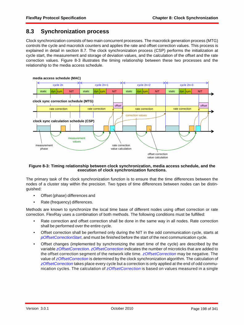
FlexRay Protocol Specification Chapter 8: Clock Synchronization
8.3 Synchronization processClock synchronization consists of two main concurrent processes. The macrotick generation process (MTG)controls the cycle and macrotick counters and applies the rate and offset correction values. This process isexplained in detail in section 8.7. The clock synchronization process (CSP) performs the initialization atcycle start, the measurement and storage of deviation values, and the calculation of the offset and the ratecorrection values. Figure 8-3 illustrates the timing relationship between these two processes and therelationship to the media access schedule.
Figure 8-3: Timing relationship between clock synchronization, media access schedule, and the execution of clock synchronization functions.
The primary task of the clock synchronization function is to ensure that the time differences between thenodes of a cluster stay within the precision. Two types of time differences between nodes can be distin-guished:
• Offset (phase) differences and • Rate (frequency) differences.
Methods are known to synchronize the local time base of different nodes using offset correction or ratecorrection. FlexRay uses a combination of both methods. The following conditions must be fulfilled:
• Rate correction and offset correction shall be done in the same way in all nodes. Rate correctionshall be performed over the entire cycle.
• Offset correction shall be performed only during the NIT in the odd communication cycle, starts atpOffsetCorrectionStart, and must be finished before the start of the next communication cycle.
• Offset changes (implemented by synchronizing the start time of the cycle) are described by thevariable zOffsetCorrection. zOffsetCorrection indicates the number of microticks that are added tothe offset correction segment of the network idle time. zOffsetCorrection may be negative. Thevalue of zOffsetCorrection is determined by the clock synchronization algorithm. The calculation ofzOffsetCorrection takes place every cycle but a correction is only applied at the end of odd commu-nication cycles. The calculation of zOffsetCorrection is based on values measured in a single
media access schedule (MAC)
clock sync correction schedule (MTG)
clock sync calculation schedule (CSP)
rate correction rate correction
NITstatic
rate correction rate correctionoffset
measurementphase
dyn. static static static
rate correction value calculation
offset correction value calculation
cycle 2n cycle 2n+1 cycle 2n+2 cycle 2n+3
measurementvalues
correction values
offset
dyn. dyn. dyn.sym. NITsym. NITsym. NITsym.
Version 3.0.1 October 2010 Page 198 of 341
FlexRay Protocol Specification Chapter 8: Clock Synchronization
communication cycle. Although the SDL indicates that this computation cannot begin before theNIT, an implementation may start the computation of this parameter within the dynamic segment orsymbol window as long as the reaction to the computation (update of the CHI and transmission ofthe SyncCalcResult and offset calc ready signals) is delayed until the NIT. The calculation must becomplete before the offset correction phase begins.
• Rate (frequency) changes are described by the variable zRateCorrection. zRateCorrection is aninteger number of microticks that are added to the configured number of microticks in a communica-tion cycle (pMicroPerCycle)110. zRateCorrection may be negative. The value of zRateCorrection isdetermined by the clock synchronization algorithm and is only computed once per double cycle. Thecalculation of zRateCorrection takes place following the static segment in an odd cycle. The calcula-tion of zRateCorrection is based on the values measured in an even-odd double cycle. Although theSDL indicates that this computation cannot begin before the NIT, an implementation may start thecomputation of this parameter within the dynamic segment or symbol window as long as thereaction to the computation (update of the CHI and transmission of the SyncCalcResult and ratecalc ready signals) is delayed until the NIT. The calculation must be completed before the next evencycle begins.
The following data types will be used in the definition of the clock synchronization process:newtype T_EvenOdd
literals even, odd;endnewtype;syntype
T_Deviation = T_Microtick endsyntype;
Definition 8-2: Formal definition of T_EvenOdd and T_Deviation.
The protocol operation control (POC) process sets the operating mode for the clock synchronizationprocess (CSP) (Figure 8-5) into one of the following modes:
1. In the STANDBY mode the clock synchronization process is effectively halted.2. In the NOSYNC mode CSP performs clock synchronization under the assumption that it is not trans-
mitting sync frames (i.e., it does not include its own clock in the clock correction computations).3. In the SYNC mode CSP performs clock synchronization under the assumption that it is transmitting
sync frames (i.e., it includes its own clock in the clock correction computations).
Definition 8-3 gives the formal definition of the CSP operating modes.newtype T_CspMode
literals STANDBY, NOSYNC, SYNC;endnewtype;newtype T_SyncCalcResult
literals WITHIN_BOUNDS, EXCEEDS_BOUNDS, MISSING_TERM;endnewtype;
Definition 8-3: Formal definition of T_CspMode and T_SyncCalcResult.
After the POC sets the CSP mode to something other than STANDBY, the CSP waits in the CSP:wait forstartup state until the POC forces the node to a coldstart or to integrate into a cluster. The startup procedure,including its initialization and interaction with other processes, is described in the macroINTEGRATION_CONTROL, which is explained in section 8.4.
Before further explanation of the processes an array is defined (Definition 8-4) which is used to store theframe IDs of the sync frames that are considered in the clock correction process.
110 pMicroPerCycle is the configured number of microticks per communication cycle without correction.
Version 3.0.1 October 2010 Page 199 of 341
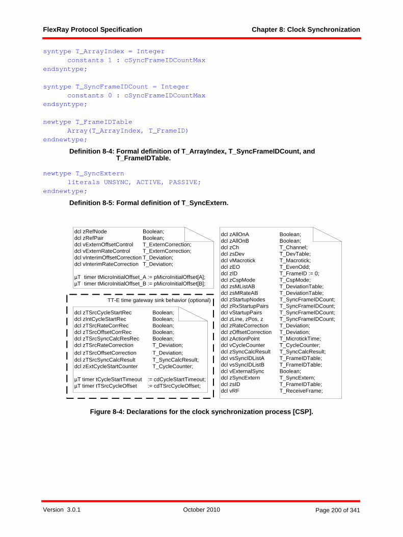
FlexRay Protocol Specification Chapter 8: Clock Synchronization
syntype T_ArrayIndex = Integer constants 1 : cSyncFrameIDCountMax
endsyntype;
syntype T_SyncFrameIDCount = Integer constants 0 : cSyncFrameIDCountMax
endsyntype;
newtype T_FrameIDTableArray(T_ArrayIndex, T_FrameID)
endnewtype;
Definition 8-4: Formal definition of T_ArrayIndex, T_SyncFrameIDCount, and T_FrameIDTable.
newtype T_SyncExternliterals UNSYNC, ACTIVE, PASSIVE;
endnewtype;
Definition 8-5: Formal definition of T_SyncExtern.
Figure 8-4: Declarations for the clock synchronization process [CSP].
dcl zAllOnA Boolean;dcl zAllOnB Boolean;dcl zCh T_Channel;dcl zsDev T_DevTable;dcl vMacrotick T_Macrotick;dcl zEO T_EvenOdd;dcl zID T_FrameID := 0;dcl zCspMode T_CspMode;dcl zsMListAB T_DeviationTable;dcl zsMRateAB T_DeviationTable;dcl zStartupNodes T_SyncFrameIDCount;dcl zRxStartupPairs T_SyncFrameIDCount;dcl vStartupPairs T_SyncFrameIDCount;dcl zLine, zPos, z T_SyncFrameIDCount;dcl zRateCorrection T_Deviation;dcl zOffsetCorrection T_Deviation;dcl zActionPoint T_MicrotickTime;dcl vCycleCounter T_CycleCounter;dcl zSyncCalcResult T_SyncCalcResult;dcl vsSyncIDListA T_FrameIDTable;dcl vsSyncIDListB T_FrameIDTable;dcl vExternalSync Boolean;dcl zSyncExtern T_SyncExtern;dcl zsID T_FrameIDTable;dcl vRF T_ReceiveFrame;
dcl zRefNode Boolean;dcl zRefPair Boolean;dcl vExternOffsetControl T_ExternCorrection;dcl vExternRateControl T_ExternCorrection;dcl vInterimOffsetCorrection T_Deviation; dcl vInterimRateCorrection T_Deviation;
µT timer tMicroInitialOffset_A := pMicroInitialOffset[A];µT timer tMicroInitialOffset_B := pMicroInitialOffset[B];
dcl zTSrcCycleStartRec Boolean;dcl zIntCycleStartRec Boolean;dcl zTSrcRateCorrRec Boolean;dcl zTSrcOffsetCorrRec Boolean;dcl zTSrcSyncCalcResRec Boolean;dcl zTSrcRateCorrection T_Deviation;dcl zTSrcOffsetCorrection T_Deviation;dcl zTSrcSyncCalcResult T_SyncCalcResult;dcl zExtCycleStartCounter T_CycleCounter;
µT timer tCycleStartTimeout := cdCycleStartTimeout;µT timer tTSrcCycleOffset := cdTSrcCycleOffset;
TT-E time gateway sink behavior (optional)
Version 3.0.1 October 2010 Page 200 of 341
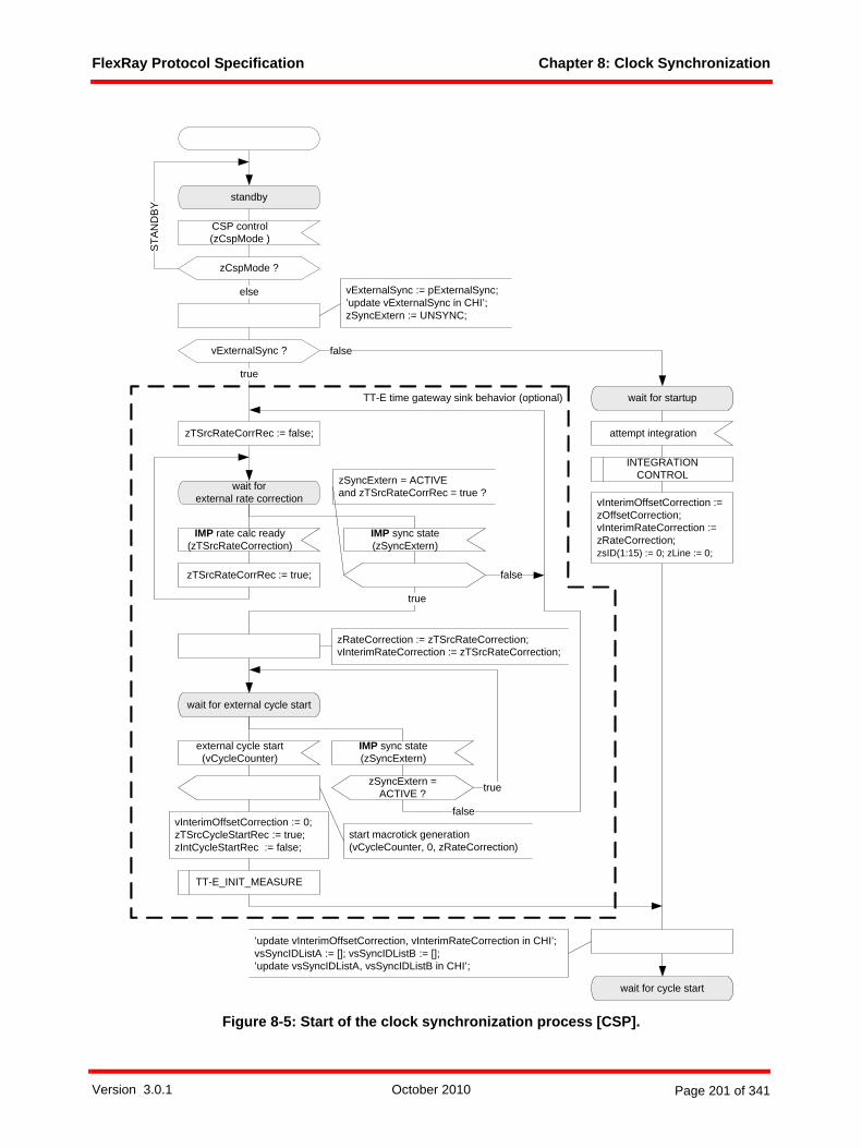
FlexRay Protocol Specification Chapter 8: Clock Synchronization
Figure 8-5: Start of the clock synchronization process [CSP].
standby
CSP control(zCspMode )
zCspMode ?
STAN
DB
Y
else
wait for startup
attempt integration
INTEGRATION CONTROL
’update vInterimOffsetCorrection, vInterimRateCorrection in CHI’;vsSyncIDListA := []; vsSyncIDListB := [];’update vsSyncIDListA, vsSyncIDListB in CHI’;
wait for cycle start
vExternalSync ? false
true
wait forexternal rate correction
wait for external cycle start
external cycle start(vCycleCounter)
start macrotick generation (vCycleCounter, 0, zRateCorrection)
IMP sync state(zSyncExtern)
false
IMP sync state(zSyncExtern)
false
vExternalSync := pExternalSync;’update vExternalSync in CHI’;zSyncExtern := UNSYNC;
zSyncExtern = ACTIVE ? true
vInterimOffsetCorrection := 0;zTSrcCycleStartRec := true;zIntCycleStartRec := false;
true
IMP rate calc ready(zTSrcRateCorrection)
zRateCorrection := zTSrcRateCorrection;vInterimRateCorrection := zTSrcRateCorrection;
zTSrcRateCorrRec := false;
zTSrcRateCorrRec := true;
zSyncExtern = ACTIVE and zTSrcRateCorrRec = true ?
TT-E time gateway sink behavior (optional)
vInterimOffsetCorrection := zOffsetCorrection;vInterimRateCorrection := zRateCorrection;zsID(1:15) := 0; zLine := 0;
TT-E_INIT_MEASURE
Version 3.0.1 October 2010 Page 201 of 341
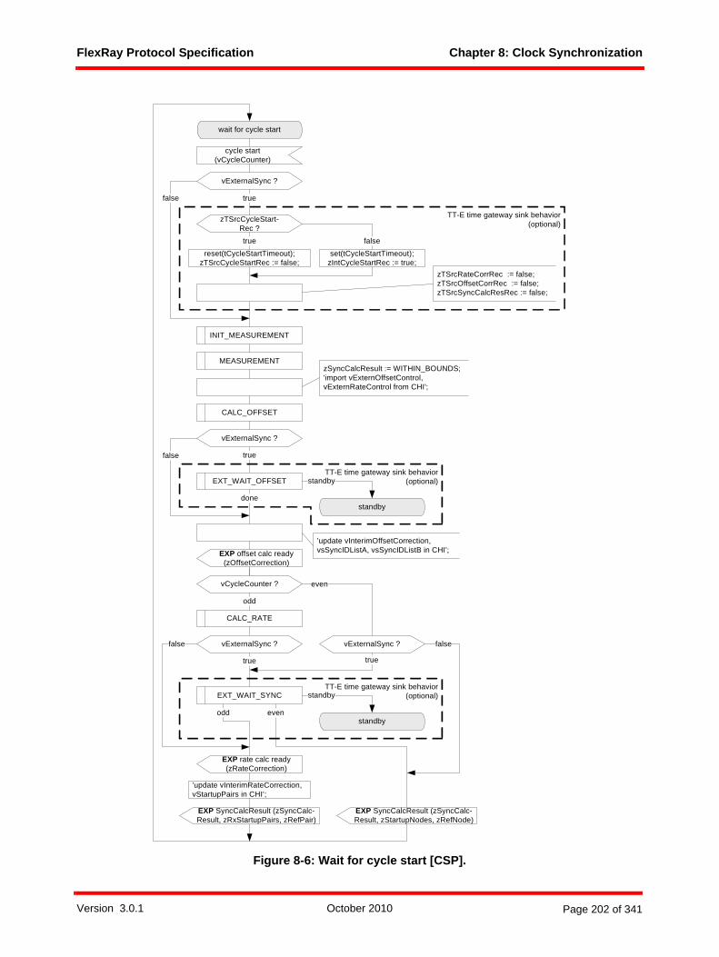
FlexRay Protocol Specification Chapter 8: Clock Synchronization
Figure 8-6: Wait for cycle start [CSP].
CALC_OFFSET
vCycleCounter ?
CALC_RATE
odd
cycle start (vCycleCounter)
wait for cycle start
EXP SyncCalcResult (zSyncCalc-Result, zStartupNodes, zRefNode)
EXP SyncCalcResult (zSyncCalc-Result, zRxStartupPairs, zRefPair)
INIT_MEASUREMENT
MEASUREMENTzSyncCalcResult := WITHIN_BOUNDS;'import vExternOffsetControl, vExternRateControl from CHI';
even
zTSrcCycleStart-Rec ?
set(tCycleStartTimeout);zIntCycleStartRec := true;
falsereset(tCycleStartTimeout);
zTSrcCycleStartRec := false;
true
vExternalSync ?
truefalse
EXP offset calc ready (zOffsetCorrection)
TT-E time gateway sink behavior(optional)
zTSrcRateCorrRec := false;zTSrcOffsetCorrRec := false;zTSrcSyncCalcResRec := false;
true
false
’update vInterimOffsetCorrection, vsSyncIDListA, vsSyncIDListB in CHI’;
vExternalSync ? falsevExternalSync ?
true
odd even
EXP rate calc ready (zRateCorrection)
’update vInterimRateCorrection, vStartupPairs in CHI’;
EXT_WAIT_SYNC standby
standby
TT-E time gateway sink behavior(optional)
true
vExternalSync ?
EXT_WAIT_OFFSET standby
standby
TT-E time gateway sink behavior(optional)
done
false
Version 3.0.1 October 2010 Page 202 of 341

FlexRay Protocol Specification Chapter 8: Clock Synchronization
Figure 8-7: Measurement initialization for TT-E coldstart [CSP].
After finishing the startup procedure a repetitive sequence consisting of cycle initialization (Figure 8-13), ameasurement phase (Figure 8-14), and offset (Figure 8-17) and rate (Figure 8-18) calculation is executed.All elements of this sequence are described below. The offset calculation will be done every cycle, the ratecalculation only in the odd cycles.
The clock synchronization control (Figure 8-8) handles mode changes done by the POC. It also handlesprocess termination requests sent by the POC.
TT-E_INIT_MEASURE
pChannels ?
= A&B
= A = B
zsDev(1:2)(even:odd)(A:B)!Valid := true;zsDev(1:2)(even:odd)(A:B)!Value := 0;zsDev(2)(even:odd)(A:B)!Startup := true;
zsDev(1:2)(even:odd)(A)!Valid := true;zsDev(1:2)(even:odd)(A)!Value := 0;zsDev(2)(even:odd)(A)!Startup := true;
zsDev(1:2)(even:odd)(B)!Valid := true;zsDev(1:2)(even:odd)(B)!Value := 0;zsDev(2)(even:odd)(B)!Startup := true;
zsID(1:15) := 0; zLine := 2;zsID(1) := pKeySlotID;zsID(2) := pSecondKeySlotID;zsDev(1:15)(even:odd)(A:B)!Valid := false;zsDev(1:15)(even:odd)(A:B)!Startup := false;
Version 3.0.1 October 2010 Page 203 of 341

FlexRay Protocol Specification Chapter 8: Clock Synchronization
Figure 8-8: Clock synchronization control and termination [CSP].
8.4 Startup of the clock synchronizationThe startup of the node's clock synchronization requires
• the initialization and start of the MTG process and• the initialization and start of the CSP process. This process contains the repetitive tasks of
measurement and storage of deviation values and the calculation of the offset and the ratecorrection values.
There are two ways to start the clock synchronization of a node:• The node is the leading coldstart node.• The node adopts the initialization values (cycle counter, clock rate, and cycle start time) of a running
coldstart node.
*(standby)
CSP control(zCspMode )
zCspMode ?
-
standby
STANDBY else
*
terminate CSP
terminate CSS_A,terminate CSS_B
terminate CSS_A,terminate CSS_B
reset macrotick generation
reset(tTSrcCycleOffset);reset(tCycleStartTimeout);
true
TT-E time gateway sinkbehavior (optional)
pExternalSync ?false
reset(tMicroInitialOffset_A);reset(tMicroInitialOffset_B);
Version 3.0.1 October 2010 Page 204 of 341

FlexRay Protocol Specification Chapter 8: Clock Synchronization
Figure 8-9: Integration control [CSP].
run
A_active B_active
integration aborted on A
INTEGRATION_ CONTROL
integration aborted on B
terminate CSS_B
tMicroInitialOffset_A tMicroInitialOffset_B
continue integration on A continue integration on B
coldstart
run, A_active, B_active
integration request on A integration request on B
set(tMicroInitialOffset_A); set(tMicroInitialOffset_B);
-
reset(tMicroInitialOffset_A); reset(tMicroInitialOffset_B);
run, A_active
-
integration aborted on B
reset(tMicroInitialOffset_B);
run, B_active
-
integration aborted on A
reset(tMicroInitialOffset_A);
integration successful on A (zID, zRateCorrection)
integration successful on B (zID, zRateCorrection)
terminate CSS_A
CSS_A, CSS_B
terminate CSS_A,terminate CSS_B
A_active
-
tMicroInitialOffset_A
continue integration on A
B_active
-
tMicroInitialOffset_B
continue integration on B
zOffsetCorrection := 0;zRateCorrection := 0;
pChannels
= A&B
= B
CSS_BCSS_A
= A
Version 3.0.1 October 2010 Page 205 of 341
FlexRay Protocol Specification Chapter 8: Clock Synchronization
The startup procedure will be entered when the CSP receives the signal attempt integration from the POC(see Figure 8-5). The control of the node's startup is described in the INTEGRATION_CONTROL macrodepicted in Figure 8-9.
8.4.1 Coldstart startupIf ongoing communication on the channels is not detected the POC may force the node to perform the roleof the leading coldstart node of the cluster. This causes the following actions:
• The clock synchronization startup processes on channel A and B (CSS_A, CSS_B) will be termi-nated.
• The INTEGRATION_CONTROL macro will be left.• The macrotick generation process (MTG) (Figure 8-25) leaves the MTG:wait for start state.
Depending on the initialization values, macrotick and cycle start signals are generated and distrib-uted to other processes.
• The CSP waits for the cycle start.
The CSP and MTG processes continue their schedules until the POC changes the CSP mode to STANDBYor an error is detected.
8.4.2 Integration startupIf ongoing communication is detected during startup, or if the node is not allowed to perform a coldstart, thenode attempts to integrate into the timing of the cluster by adopting the rate, the cycle number, and cyclestart instant of a coldstart node. To accomplish this, the CSP process (Figure 8-9) instantiates the clocksynchronization startup processes for channel A and B (CSS_A, CSS_B).
After their instantiation, the CSS_A process (Figure 8-11) and the CSS_B process wait for a signal from thecoding/decoding unit that a potential frame start was detected. The CSS process then takes a timestampand waits for a signal indicating that a valid even startup frame was received. If no valid even startup framewas received the time stamp will be overwritten with the time stamp of the next potential frame start that isreceived.
When a valid even startup frame is received the node is able to pre-calculate the initial values for the cyclecounter and the macrotick counter. The node then waits for the corresponding odd startup frame. This frameis expected in a time window. When a potential frame start is detected in this time window the tMicroInitial-Offset timer is started in the INTEGRATION_CONTROL macro. When this timer expires the MTG process(Figure 8-25) is started using the pre-calculated initial values. A second potential frame start inside the timewindow leads to a restart of the tMicroInitialOffset timer. Only one channel can start the MTG process (theinitial channel).111 Between the expiration of the timer tMicroInitialOffset and the reception of the completestartup frame, the other channel (the non-initial channel) can not start, stop, or change the MTG process,but it can receive potential frame start events and can start its own tMicroInitialOffset timer. The behavior ofthe CSS process of the non-initial channel is the same as the behavior of the CSS process of the initialchannel except that the non-initial channel is unable to start the MTG process and is unable to terminateitself and the CSS process of the other channel.
111 There is no configuration that selects the channel that starts the MTG process. The process is started by the first channel that receives a potential frame start in the expected time window after reception of a valid even startup frame on the same channel (refer to Figure 8-11).
Version 3.0.1 October 2010 Page 206 of 341

FlexRay Protocol Specification Chapter 8: Clock Synchronization
Figure 8-10: Termination of the CSS process [CSS_A].
*
terminate CSS_A
Version 3.0.1 October 2010 Page 207 of 341

FlexRay Protocol Specification Chapter 8: Clock Synchronization
Figure 8-11: Clock synchronization startup process on channel A [CSS_A]112.
112 The priority input symbol on the CSS_A:wait for second startup frame state has been included to resolve the ambiguity that arises if the timer tSecondFrame expires at the same time a valid odd startup frame on A signal is received.
potential frame start on A
wait for second startup frame
false
zRateCorrection := now - zFrameStart - pMicroPerCycle;
start macrotick generation (vCycle-Counter, vMacrotick, zRateCorrection)
trueframe too early ?
frame too late
vRF!Header!FrameID ?
true
= zID
else
zID := vRF!Header!FrameID;vCycleCounter := (vRF!Header!CycleCount + 1) mod (gCycleCountMax + 1);vMacrotick := (zID -1) * gdStaticSlot + pMacroInitialOffset[A];reset(tID); set(tSecondFrame);
valid even startup frame on A (vRF)
wait for first startup frame
zFrameStart := 0; zID := 0;
integration started on A
tSecondFrame
integration aborted on A
false
frame too late ?
dcl zRateCorrection T_Deviation;dcl vRF T_ReceiveFrame;dcl zID T_FrameID := 0;dcl vCycleCounter T_CycleCounter;dcl zFrameStart T_MicrotickTime;dcl vMacrotick T_Macrotick;µT timer tID := 2 * (pMicroPerCycle + pRateCorrectionOut);µT timer tSecondFrame := pMicroPerCycle + pRateCorrectionOut;dcl zIntegration Boolean := false;dcl zPotFrameStart Boolean;
vRF!Header!FrameID ? = zID
else
zIntegration := true;
zIntegration ?
true
false
zIntegration := false;zPotFrameStart := false;
tID
zID := 0;
set(tID);reset(tSecondFrame);
potential frame start on A
zFrameStart := now;zPotFrameStart := true;
zPotFrameStart ?
true
false
continue integration on A
integration request on A
reset macrotick generation
zIntegration ?
true
false
integration successful on A (zID, zRateCorrection)
vRF!Header!CycleCount = vCycleCounter ? false
true
valid odd startup frame on A (vRF)
pMicroPerCycle - pRateCorrectionOut > now -
zFrameStart ?
pMicroPerCycle + pRateCorrectionOut < now -
zFrameStart ?
Version 3.0.1 October 2010 Page 208 of 341
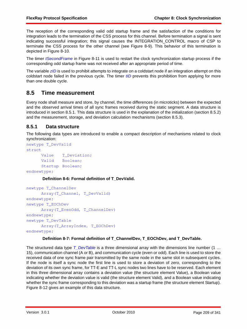
FlexRay Protocol Specification Chapter 8: Clock Synchronization
The reception of the corresponding valid odd startup frame and the satisfaction of the conditions forintegration leads to the termination of the CSS process for this channel. Before termination a signal is sentindicating successful integration; this signal causes the INTEGRATION_CONTROL macro of CSP toterminate the CSS process for the other channel (see Figure 8-9). This behavior of this termination isdepicted in Figure 8-10.
The timer tSecondFrame in Figure 8-11 is used to restart the clock synchronization startup process if thecorresponding odd startup frame was not received after an appropriate period of time.
The variable zID is used to prohibit attempts to integrate on a coldstart node if an integration attempt on thiscoldstart node failed in the previous cycle. The timer tID prevents this prohibition from applying for morethan one double cycle.
8.5 Time measurementEvery node shall measure and store, by channel, the time differences (in microticks) between the expectedand the observed arrival times of all sync frames received during the static segment. A data structure isintroduced in section 8.5.1. This data structure is used in the explanation of the initialization (section 8.5.2)and the measurement, storage, and deviation calculation mechanisms (section 8.5.3).
8.5.1 Data structureThe following data types are introduced to enable a compact description of mechanisms related to clocksynchronization:newtype T_DevValidstruct
Value T_Deviation;Valid Boolean;Startup Boolean;
endnewtype;
Definition 8-6: Formal definition of T_DevValid.
newtype T_ChannelDevArray(T_Channel, T_DevValid)
endnewtype;newtype T_EOChDev
Array(T_EvenOdd, T_ChannelDev)endnewtype;newtype T_DevTable
Array(T_ArrayIndex, T_EOChDev)endnewtype;
Definition 8-7: Formal definition of T_ChannelDev, T_EOChDev, and T_DevTable.
The structured data type T_DevTable is a three dimensional array with the dimensions line number (1 …15), communication channel (A or B), and communication cycle (even or odd). Each line is used to store thereceived data of one sync frame pair transmitted by the same node in the same slot in subsequent cycles.If the node is itself a sync node the first line is used to store a deviation of zero, corresponding to thedeviation of its own sync frame, for TT-E and TT-L sync nodes two lines have to be reserved. Each elementin this three dimensional array contains a deviation value (the structure element Value), a Boolean valueindicating whether the deviation value is valid (the structure element Valid), and a Boolean value indicatingwhether the sync frame corresponding to this deviation was a startup frame (the structure element Startup).Figure 8-12 gives an example of this data structure.
Version 3.0.1 October 2010 Page 209 of 341
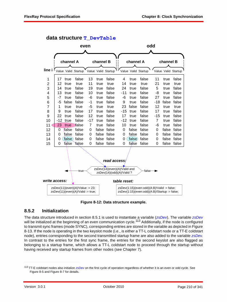
FlexRay Protocol Specification Chapter 8: Clock Synchronization
Figure 8-12: Data structure example.
8.5.2 InitializationThe data structure introduced in section 8.5.1 is used to instantiate a variable (zsDev). The variable zsDevwill be initialized at the beginning of an even communication cycle.113 Additionally, if the node is configuredto transmit sync frames (mode SYNC), corresponding entries are stored in the variable as depicted in Figure8-13. If the node is operating in the two keyslot mode (i.e., is either a TT-L coldstart node or a TT-E coldstartnode), entries corresponding to the second transmitted startup frame are also added to the variable zsDev.In contrast to the entries for the first sync frame, the entries for the second keyslot are also flagged asbelonging to a startup frame, which allows a TT-L coldstart node to proceed through the startup withouthaving received any startup frames from other nodes (see Chapter 7).
113 TT-E coldstart nodes also initialize zsDev on the first cycle of operation regardless of whether it is an even or odd cycle. See Figure 8-5 and Figure 8-7 for details.
channel A channel B channel A channel B
even odd
line i
123456789
101112131415
zsDev(11)(even)(A)!Value := 23;zsDev(11)(even)(A)!Valid := true;
data structure T_DevTable
zsDev(14)(even)(A)!Valid andzsDev(14)(odd)(A)!Valid ?
read access:
write access: table reset:zsDev(1:15)(even:odd)(A:B)!Valid := false;zsDev(1:15)(even:odd)(A:B)!Startup := false;
falsetrue
Value Valid Startup Value Valid Startup Value Valid Startup Value Valid Startup
17121413-7-51922-12230000
truetruetruetruetruefalsetruetruetruetruetruefalsefalsefalsefalse
falsetruefalsefalsefalsefalsetruefalsefalsefalsefalsefalsefalsefalsefalse
13111910-6-1-51712-1770000
truetruetruetruetruetruetruetruetruetruetruefalsefalsefalsefalse
falsetruefalsefalsefalsefalsetruefalsefalsefalsefalsefalsefalsefalsefalse
41424-11-6923-1517-12100000
truetruetruetruetruetruefalsetruetruetruetruefalsefalsefalsefalse
falsetruefalsefalsefalsefalsefalsefalsefalsefalsefalsefalsefalsefalsefalse
11215-827-181217-157-60000
truetruetruetruetruefalsetruetruetruetruetruefalsefalsefalsefalse
falsetruefalsefalsefalsefalsetruefalsefalsefalsefalsefalsefalsefalsefalse
Version 3.0.1 October 2010 Page 210 of 341
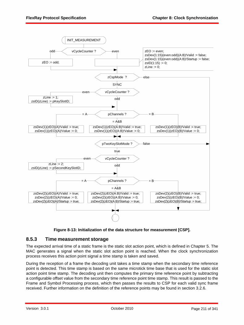
FlexRay Protocol Specification Chapter 8: Clock Synchronization
Figure 8-13: Initialization of the data structure for measurement [CSP].
8.5.3 Time measurement storageThe expected arrival time of a static frame is the static slot action point, which is defined in Chapter 5. TheMAC generates a signal when the static slot action point is reached. When the clock synchronizationprocess receives this action point signal a time stamp is taken and saved.
During the reception of a frame the decoding unit takes a time stamp when the secondary time referencepoint is detected. This time stamp is based on the same microtick time base that is used for the static slotaction point time stamp. The decoding unit then computes the primary time reference point by subtractinga configurable offset value from the secondary time reference point time stamp. This result is passed to theFrame and Symbol Processing process, which then passes the results to CSP for each valid sync framereceived. Further information on the definition of the reference points may be found in section 3.2.6.
INIT_MEASUREMENT
vCycleCounter ?
zEO := odd;
evenodd
zCspMode ?
SYNC
else
pChannels ?
zsDev(1)(zEO)(A:B)!Valid := true;zsDev(1)(zEO)(A:B)!Value := 0;
zsDev(1)(zEO)(A)!Valid := true;zsDev(1)(zEO)(A)!Value := 0;
zsDev(1)(zEO)(B)!Valid := true;zsDev(1)(zEO)(B)!Value := 0;
= A&B
= A = B
pTwoKeySlotMode ? false
true
pChannels ?
zsDev(2)(zEO)(A:B)!Valid := true;zsDev(2)(zEO)(A:B)!Value := 0;
zsDev(2)(zEO)(A:B)!Startup := true;
zsDev(2)(zEO)(A)!Valid := true;zsDev(2)(zEO)(A)!Value := 0;
zsDev(2)(zEO)(A)!Startup := true;
zsDev(2)(zEO)(B)!Valid := true;zsDev(2)(zEO)(B)!Value := 0;
zsDev(2)(zEO)(B)!Startup := true;
= A&B
= A = B
zEO := even;zsDev(1:15)(even:odd)(A:B)!Valid := false;zsDev(1:15)(even:odd)(A:B)!Startup := false;zsID(1:15) := 0;zLine := 0;
vCycleCounter ?
odd
evenzLine := 1;
zsID(zLine) := pKeySlotID;
vCycleCounter ?
odd
even
zLine := 2;zsID(zLine) := pSecondKeySlotID;
Version 3.0.1 October 2010 Page 211 of 341
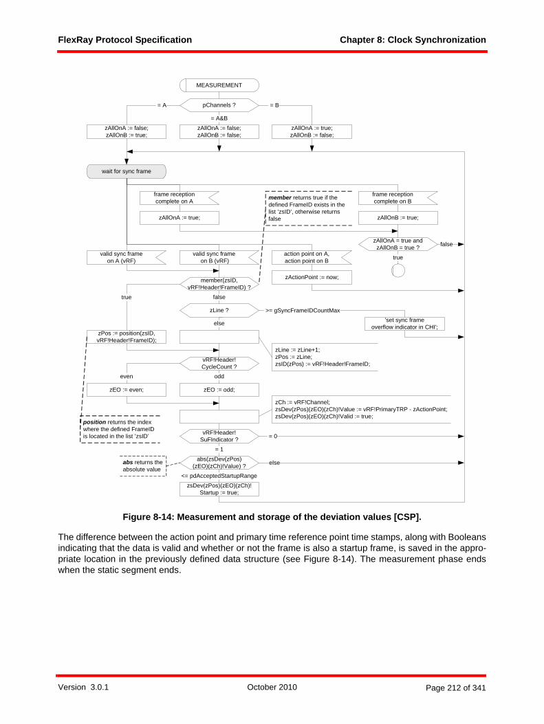
FlexRay Protocol Specification Chapter 8: Clock Synchronization
Figure 8-14: Measurement and storage of the deviation values [CSP].
The difference between the action point and primary time reference point time stamps, along with Booleansindicating that the data is valid and whether or not the frame is also a startup frame, is saved in the appro-priate location in the previously defined data structure (see Figure 8-14). The measurement phase endswhen the static segment ends.
wait for sync frame
valid sync frameon A (vRF)
member(zsID, vRF!Header!FrameID) ?
zPos := position(zsID, vRF!Header!FrameID);
true false
else
zLine ? >= gSyncFrameIDCountMax
action point on A,action point on B
zActionPoint := now;
MEASUREMENT
true
vRF!Header! CycleCount ?
zEO := even; zEO := odd;
even odd
vRF!Header!SuFIndicator ? = 0
abs(zsDev(zPos) (zEO)(zCh)!Value) ?
= 1
else
zsDev(zPos)(zEO)(zCh)!Startup := true;
<= pdAcceptedStartupRange
valid sync frame on B (vRF)
'set sync frame overflow indicator in CHI';
abs returns the absolute value
frame reception complete on A
frame reception complete on B
zAllOnA := true; zAllOnB := true;
zAllOnA = true and zAllOnB = true ? false
zAllOnA := true; zAllOnB := false;
pChannels ?
zAllOnA := false; zAllOnB := false;
zAllOnA := false; zAllOnB := true;
= A&B
= A = B
zCh := vRF!Channel;zsDev(zPos)(zEO)(zCh)!Value := vRF!PrimaryTRP - zActionPoint;zsDev(zPos)(zEO)(zCh)!Valid := true;
zLine := zLine+1; zPos := zLine;zsID(zPos) := vRF!Header!FrameID;
member returns true if the defined FrameID exists in the list ’zsID’, otherwise returns false
position returns the index where the defined FrameID is located in the list ’zsID’
Version 3.0.1 October 2010 Page 212 of 341
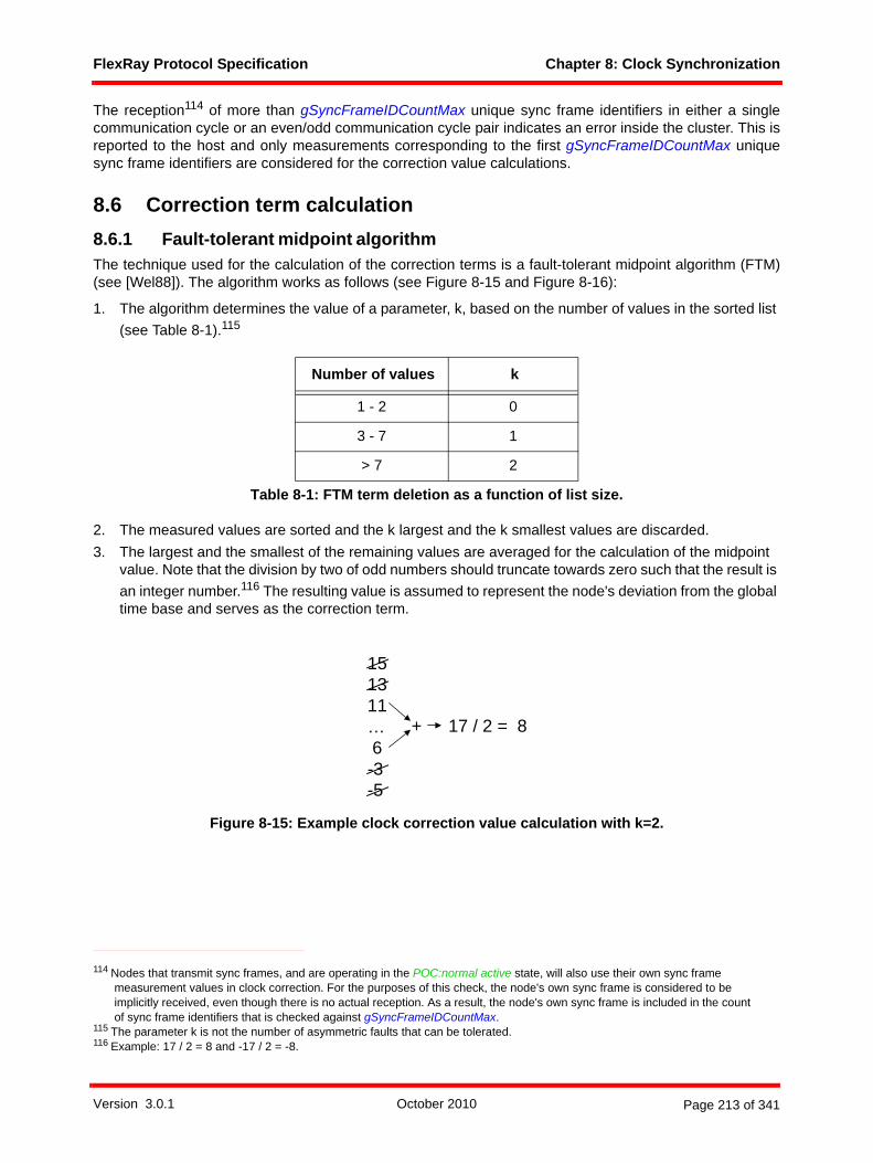
FlexRay Protocol Specification Chapter 8: Clock Synchronization
The reception114 of more than gSyncFrameIDCountMax unique sync frame identifiers in either a singlecommunication cycle or an even/odd communication cycle pair indicates an error inside the cluster. This isreported to the host and only measurements corresponding to the first gSyncFrameIDCountMax uniquesync frame identifiers are considered for the correction value calculations.
8.6 Correction term calculation8.6.1 Fault-tolerant midpoint algorithmThe technique used for the calculation of the correction terms is a fault-tolerant midpoint algorithm (FTM)(see [Wel88]). The algorithm works as follows (see Figure 8-15 and Figure 8-16):
1. The algorithm determines the value of a parameter, k, based on the number of values in the sorted list (see Table 8-1).115
2. The measured values are sorted and the k largest and the k smallest values are discarded.3. The largest and the smallest of the remaining values are averaged for the calculation of the midpoint
value. Note that the division by two of odd numbers should truncate towards zero such that the result is an integer number.116 The resulting value is assumed to represent the node's deviation from the global time base and serves as the correction term.
Figure 8-15: Example clock correction value calculation with k=2.
114 Nodes that transmit sync frames, and are operating in the POC:normal active state, will also use their own sync frame measurement values in clock correction. For the purposes of this check, the node's own sync frame is considered to be implicitly received, even though there is no actual reception. As a result, the node's own sync frame is included in the count of sync frame identifiers that is checked against gSyncFrameIDCountMax.
Number of values k
1 - 2 0
3 - 7 1
> 7 2
Table 8-1: FTM term deletion as a function of list size.
115 The parameter k is not the number of asymmetric faults that can be tolerated.116 Example: 17 / 2 = 8 and -17 / 2 = -8.
151311… 6-3-5
17 / 2 = 8+
Version 3.0.1 October 2010 Page 213 of 341

FlexRay Protocol Specification Chapter 8: Clock Synchronization
Figure 8-16: Fault-Tolerant Midpoint Procedure [CSP].
8.6.2 Calculation of the offset correction valueThe offset correction value zOffsetCorrection is a signed integer that indicates how many microticks thenode should shift the start of its cycle. Negative values mean the NIT should be shortened (making the nextcycle start earlier). Positive values mean the NIT should be lengthened (making the next cycle start later).
In Figure 8-17 the procedure of the calculation of the offset correction value is described in detail. Thefollowing steps are covered in the SDL diagram in Figure 8-17:
1. Selection of the previously stored deviation values. Only deviation values that were measured and stored in the current communication cycle are used. If a given sync frame ID has two deviation values (one for channel A and one for channel B) the smaller value will be selected.
2. The number of received sync frames is checked and if an insufficient117 number of sync frames was received the error condition MISSING_TERM is set.
3. The fault-tolerant midpoint algorithm is executed (see section 8.6.1).4. The correction term is checked against specified limits. If the correction term is outside of the specified
limits the error condition is set to EXCEEDS_BOUNDS and the correction term is set to the maximum or minimum value as appropriate (see section 8.6.4).
5. If appropriate, an external correction value supplied by the host is added to the calculated and checked correction term (see section 8.6.5).
The following data structure is used to save and handle the selected data:
117 The number of sync frames that need to be received to be considered sufficient depends on the synchronization mode and the node's role. For devices in a TT-D cluster, and for non-coldstart nodes in a TT-E or TT-L cluster, the reception of a single valid sync frame is considered sufficient. TT-E or TT-L coldstart nodes do not need to receive any sync frames, i.e., the number of received sync frames is always considered sufficient. Figure 8-17 implements this behavior not by checking the number of received sync frames directly but rather by checking the number of entries in the zsMListAB array.
zLength := length(zList);
zLength ?
zCorrectValue := 0;
= 0
else
zList := sort(zList);
MIDTERM
zCorrectValue
zLength ? > 7
zCorrectValue := (zList(1) +zList(zLength))/2;
< 3
else
zCorrectValue := (zList(2) +zList(zLength-1))/2;
zCorrectValue := (zList(3) +zList(zLength-2))/2;
fpar zListreturns T_Deviation;
dcl zLength T_ArrayIndex;dcl zCorrectValue T_Deviation;
length returns the number ofelements contained in zList
sort returns a sorted listbeginning with the smallest andending with the largest value
Version 3.0.1 October 2010 Page 214 of 341

FlexRay Protocol Specification Chapter 8: Clock Synchronization
newtype T_DeviationTableArray(T_ArrayIndex, T_Deviation)
endnewtype;
Definition 8-8: Formal definition of T_DeviationTable.
Version 3.0.1 October 2010 Page 215 of 341
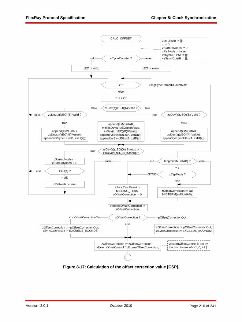
FlexRay Protocol Specification Chapter 8: Clock Synchronization
Figure 8-17: Calculation of the offset correction value [CSP].
else
>= gSyncFrameIDCountMax
length(zsMListAB) ? = 0
= 1
else
z ?
else
truefalse
true
falsetrue
false
z := z+1;
zsDev(z)(zEO)(A)!Valid ?
zsDev(z)(zEO)(B)!Valid ?
zEO := odd;
append(zsMListAB, zsDev(z)(zEO)(B)!Value);
append(vsSyncIDListB, zsID(z));
append(zsMListAB, min(zsDev(z)(zEO)(A)!Value,
zsDev(z)(zEO)(B)!Value));append(vsSyncIDListA, zsID(z));append(vsSyncIDListB, zsID(z));
append(zsMListAB, zsDev(z)(zEO)(A)!Value);
append(vsSyncIDListA, zsID(z));
zsDev(z)(zEO)(B)!Valid ?
zCspMode ?
CALC_OFFSET
> pOffsetCorrectionOut zOffsetCorrection ?
zOffsetCorrection := pOffsetCorrectionOut;zSyncCalcResult := EXCEEDS_BOUNDS;
zOffsetCorrection := -pOffsetCorrectionOut;zSyncCalcResult := EXCEEDS_BOUNDS;
< -pOffsetCorrectionOut
else
vCycleCounter ?
zEO := even;
odd even
zStartupNodes := zStartupNodes + 1;
zsDev(z)(zEO)(A)!Startup or zsDev(z)(zEO)(B)!Startup ?true
zsID(z) ?
zRefNode := true;
= zID
false
SYNC
else
zOffsetCorrection := call MIDTERM(zsMListAB);
vExternOffsetControl is set by the host to one of { -1, 0, +1 }
zSyncCalcResult := MISSING_TERM;
zOffsetCorrection := 0;
zsMListAB := [];z := 0;zStartupNodes := 0;zRefNode := false;vsSyncIDListA := [];vsSyncIDListB := [];
zOffsetCorrection := zOffsetCorrection + vExternOffsetControl * pExternOffsetCorrection;
vInterimOffsetCorrection :=zOffsetCorrection;
Version 3.0.1 October 2010 Page 216 of 341

FlexRay Protocol Specification Chapter 8: Clock Synchronization
The SDL abstraction of execution in zero time could lead the reader to the conclusion that the calculationof the offset correction value needs to complete in zero time. This is of course unachievable. It is anticipatedthat real implementations may take substantial time to calculate the correction, and that implementationsmay begin the calculation earlier than is shown in Figure 8-6 (i.e., may begin the calculation during themeasurement process). Therefore the following restriction on the time required for offset correction calcu-lation is introduced:
The offset correction calculation must be completed no later than cdMaxOffsetCalculation after the end of the static segment or 1 MT after the start of the NIT, whichever occurs later.
8.6.3 Calculation of the rate correction valueThe goal of the rate correction is to bring the rates of all nodes inside the cluster close together. The ratecorrection value is determined by comparing the corresponding measured time differences from twosuccessive cycles. A detailed description is given by the SDL diagram depicted in Figure 8-18.
Version 3.0.1 October 2010 Page 217 of 341

FlexRay Protocol Specification Chapter 8: Clock Synchronization
Figure 8-18: Calculation of the rate correction value [CSP].
false
>= gSyncFrameIDCountMax
else
true false
true
false true
false
>= pClusterDriftDamping <= -pClusterDriftDamping
else
z := z+1;
CALC_RATE
z ?
zsDev(z)(even)(A)!Valid and zsDev(z)(odd)(A)!Valid ?
zsDev(z)(even)(B)!Valid andzsDev(z)(odd)(B)!Valid ?
zsDev(z)(even)(B)!Valid andzsDev(z)(odd)(B)!Valid ?
append(zsMRateAB, (zsDev(z)(odd)(A)!Value - zsDev(z)(even)(A)!Value));
append(zsMRateAB, (zsDev(z)(odd)(B)!Value - zsDev(z)(even)(B)!Value));
append(zsMRateAB, (zsDev(z)(odd)(A)!Value - zsDev(z)(even)(A)!Value + zsDev(z)(odd)(B)!Value
- zsDev(z)(even)(B)!Value)/2);
zRateCorrection := (call MIDTERM (zsMRateAB)) + zRateCorrection ;
zRateCorrection ?
zRateCorrection := 0;zRateCorrection := zRateCorrection +
pClusterDriftDamping;zRateCorrection := zRateCorrection -
pClusterDriftDamping;
> pRateCorrectionOut
else
zRateCorrection ? < -pRateCorrectionOut
zRateCorrection := -pRateCorrectionOut;zSyncCalcResult := EXCEEDS_BOUNDS;
zRateCorrection := pRateCorrectionOut;zSyncCalcResult := EXCEEDS_BOUNDS;
zRxStartupPairs := zRxStartupPairs+1;
true
zsID(z) ?
zRefPair := true;
= zID
elselength(zsMRateAB) ? = 0
= 1
else
zCspMode ?SYNC
else
zSyncCalcResult := MISSING_TERM;
zSyncCalcResult ?
EXCEEDS_BOUNDSelse
(zsDev(z)(even)(A)!Startup andzsDev(z)(odd)(A)!Startup) or (zsDev(z)(even)(B)!Startup andzsDev(z)(odd)(B)!Startup) ?
zsMRateAB := [];z := 0;zRxStartupPairs := 0;zRefPair := false;
vStartupPairs := zRxStartupPairs;
false true
vStartupPairs := zRxStartupPairs+ 1;
zRateCorrection := zRateCorrection + vExternRateControl * pExternRateCorrection;
vExternRateControl is set by the host to one of { -1, 0, +1 }
vInterimRateCorrection :=zRateCorrection;zCspMode = SYNC and
pKeySlotUsedForStartup = true ?
Version 3.0.1 October 2010 Page 218 of 341

FlexRay Protocol Specification Chapter 8: Clock Synchronization
The rate correction value zRateCorrection is a signed integer indicating by how many microticks the node'scycle length should be changed. Negative values mean the cycle should be shortened; positive valuesmean the cycle should be lengthened.
The following steps are depicted in the SDL diagram in Figure 8-18:
1. Pairs of previously stored deviation values are selected and the difference between the values within a pair is calculated. Pairs are selected that represent sync frames received on the same channel, in slots with the same slot number, on consecutive cycles. If there are two pairs for a given sync frame ID (one pair for channel A and another pair for channel B) the average of the differences is used.
2. The number of received sync frame pairs is checked and if an insufficient118 number of sync frame pairs was received the error condition MISSING_TERM is set unless the error condition EXCEEDS_BOUNDS had been set previously.119
3. The fault-tolerant midpoint algorithm is executed (see section 8.6.1).4. A damping value pClusterDriftDamping for the rate correction term is applied.5. If appropriate, an external correction value supplied by the host is added to the calculated correction
term (see section 8.6.5).6. The correction term is checked against specified limits. If the correction term exceeds the specified
limits the error condition is set to EXCEEDS_BOUNDS and the correction term is set to the maximum or minimum value as appropriate (see section 8.6.4).
In the list above division operations shall produce an integral result that is truncated towards zero.120
The pClusterDriftDamping parameter should be configured in such a way that the damping value in allnodes has approximately the same duration.121
The SDL abstraction of execution in zero time introduces similar problems for the rate correction calculationas are described in section 8.6.2 for the offset correction calculation. Therefore the following restriction onthe time required for rate correction calculation is introduced:
The rate correction calculation must be completed no later than cdMaxRateCalculation after the end of the static segment or 2 MT after the start of the NIT, whichever occurs later.
8.6.4 Value limitationsBefore applying the calculated correction values, they shall be checked against pre-configured limits (seeFigure 8-17 and Figure 8-18).
If correction values are inside the limits, the node is considered fully synchronized.
If either of the correction values is outside of the limits, the node is out of synchronization. This correspondsto an error condition. Information on the handling of this situation is specified in Chapter 2.
The correction values are inside the limits if:
- pRateCorrectionOut <= zRateCorrection <= pRateCorrectionOut
118 The number of sync frame pairs that need to be received to be considered sufficient depends on the synchronization mode and the node's role. For devices in a TT-D cluster, and for non-coldstart nodes in a TT-E or TT-L cluster, the reception of a single valid sync frame pair is considered sufficient. TT-E or TT-L coldstart nodes do not need to receive any sync frames, i.e., the number of received sync frame pairs is always considered sufficient. Figure 8-18 implements this behavior not by checking the number of received sync frame pairs directly but rather by checking the number of entries in the zsMRateAB array.
119 The consequence of this behavior is that in a TT-D cluster operating with only a single sync node the sync node would detect MISSING_TERM before the non-sync nodes. The non-sync nodes would not detect MISSING_TERM until the last sync node has stopped transmitting, presumably due to loss of synchronization. As a consequence, in this circumstance different types of nodes would cease operation at different times.
120 Example: 17 / 2 = 8 and -17 / 2 = -8.121 A node-specific configuration value is used to allow clusters that have different microtick durations in different nodes.
Version 3.0.1 October 2010 Page 219 of 341

FlexRay Protocol Specification Chapter 8: Clock Synchronization
- pOffsetCorrectionOut <= zOffsetCorrection <= pOffsetCorrectionOut
If both correction values are inside the limits the correction will be performed; if either value exceeds its pre-configured limit, an error is reported and the node enters the POC:normal passive or the POC:halt statedepending on the configured behavior (see Chapter 2). If a value is outside its pre-configured limit it isreduced or increased to its limit. If operation continues, the correction is performed with this modified value.
8.6.5 Host-controlled external clock synchronizationDuring normal operation independent clusters can drift significantly. If synchronous operation is desiredacross multiple clusters, external synchronization is necessary even though the nodes within each clusterare synchronized. This can be accomplished by the synchronous application of host-controlled external rateand offset correction terms to both clusters.
The control data vExternRateControl and vExternOffsetControl of the external clock correction have threedifferent values, +1 / -1 / 0, with the following meanings:
The size of the external rate and the external offset correction values pExternOffsetCorrection and pExtern-RateCorrection are fixed and configured in the POC:config state.
The application must ensure that the external offset correction is performed in the same cycle with the samevalue in all nodes of a cluster and that the external rate correction is performed in the same double cyclewith the same value in all nodes of a cluster.
The type is defined as follows:syntype T_ExternCorrection = Integer
constants -1, 0, +1endsyntype;
Definition 8-9: Formal definition of T_ExternCorrection.
The handling of the external correction values is depicted in Figure 8-17 and Figure 8-18.
The configuration must ensure that the addition of the external correction value can be performed even ifthe pre-configured limit is exceeded by the addition of an external correction term.
8.6.6 TT-E time gateway sink correction determinationA node operating as TT-E coldstart node supports additional functionality which is described in Figures 8-19 to 8-24. This functionality is optional and is shown in the SDL diagrams as a dashed outline box labeled"TT-E time gateway sink behavior".
A TT-E coldstart node calculates the clock correction values as any other node in the cluster based on themeasured deviation between the expected and the observed arrival times of the sync frames, even thoughthe calculated clock correction values will eventually be overwritten by the clock correction values providedby the time gateway source node.
Value: +1 -1 0
rate correctionvExternRateControl
increase cycle length by pExternRateCorrection
decrease cycle length by pExternRateCorrection no change
offset correctionvExternOffsetControl
start cycle later by pExternOffsetCorrection
start cycle earlier by pExternOffsetCorrection no change
Table 8-2: External clock correction control.
Version 3.0.1 October 2010 Page 220 of 341

FlexRay Protocol Specification Chapter 8: Clock Synchronization
If a TT-E coldstart node is configured to switch to the local synchronization method in case the synchroni-zation with the time gateway source node is lost, it will use the clock correction values it has calculated itself.However, as a TT-E coldstart node configured to switch to the local synchronization method must neces-sarily be the sole coldstart node of the TT-E cluster, the calculated correction values will always be zero,just as they are for a TT-L coldstart node.
Figure 8-19: Cycle start supervision [CSP].
Figure 8-19 above describes how the time gateway sink node continuously monitors that its locallygenerated cycle start signal is still synchronous to the one periodically sent by its time gateway source node.Should the externally generated cycle start event and the locally generated cycle start event be cdCycle-StartTimeout or more microticks apart, the time gateway sink node assumes that it has lost synchronizationto the time gateway source node (see Figure 8-24).
external cycle start
true
set(tCycleStartTimeout);zTSrcCycleStartRec := true; standby
standby
fallbackreset(tCycleStartTimeout);zIntCycleStartRec := false;
zIntCycleStartRec ?
true
false
vExternalSync ?
true
-
false
TT-E time gateway sink behavior(optional)
wait for sync frame, wait for cycle start, wait for cycle start imminent,wait for offset correction start imminent
vExternalSync ? false
tCycleStartTimeout
EXT_SYNC_ERROR
Version 3.0.1 October 2010 Page 221 of 341

FlexRay Protocol Specification Chapter 8: Clock Synchronization
Figure 8-20: External cycle start delay [CSP].
The delay timer tTSrcCycleOffset provides a delay between the cycle starts of the time gateway source andtime gateway sink clusters. It is intended that this offset is a protocol constant (i.e., cdTSrcCycleOffset). TheSDL description makes the assumption that the cycle start event propagates across the time gatewayinterface in zero time, and thus the SDL describes a delay that is equal to the delay that is required betweenthe two cycle starts. In practice, propagation across the time gateway interface will not take place in zerotime – an implementation must take this propagation time into account but still provide an offset of cdTSrc-CycleOffset between the cycle starts in the two clusters. Note that this may require an implementation toprovide one or more configuration parameters, not described in this specification, if the propagation delayacross the time gateway interface is not under the control of the implementation (for example, if the timegateway interface is external to the implementation).
*
IMP cycle start(zExtCycleStartCounter)
TT-E time gateway sink behavior (optional)
set(tTSrcCycleOffset);
tTSrcCycleOffset
external cycle start(zExtCycleStartCounter)
-
An implementation must take the propagation delay of the time gateway interface into account but still provide an offset of cdTSrcCycleOffset between the cycle starts of the source and sink clusters.
vExternalSync ?
true
false
Version 3.0.1 October 2010 Page 222 of 341

FlexRay Protocol Specification Chapter 8: Clock Synchronization
Figure 8-21: Obtain external clock sync signals [CSP].
The time gateway sink node continuously monitors the time gateway interface and stores any receivedupdates of clock correction values as depicted in Figure 8-21. Should the time gateway source node indicatethat it is neither in the state POC:normal active nor in the state POC:normal passive, the time gateway sinknode will behave as if it has lost synchronization to the time gateway source node (see Figure 8-24).
If the time gateway sink node is the sole provider of startup frames of the cluster, it must not switch toPOC:normal passive. To that end, the node overwrites the zSyncCalcResult value of the time gatewaysource node with the fault free value "WITHIN_BOUNDS" if it is configured to "fall back" to the local synchro-nization method, which implies that it is the sole coldstart node. If several TT-E coldstart nodes are presentin the cluster, it is obviously important that they all agree upon the schedule. Should the time gatewaysource node of one of the time gateway sink nodes have a problem with its clock synchronization, it cannotascertain the validity of its view on the time source cluster schedule. Therefore, its time gateway sink nodeshould (also) enter POC:normal passive and only return to POC:normal active when its time gateway sourcenode has recovered its synchronization with the time source cluster.
TT-E time gateway sink behavior(optional)
true
vExternalSync ?
true false
vExternalSync ?
false
IMP rate calc ready(zTSrcRateCorrection)
IMP offset calc ready(zTSrcOffsetCorrection)
zTSrcRateCorrRec := true;zTSrcOffsetCorrRec :=true;
wait for sync frame, wait for cycle start,wait for cycle start imminent, wait foroffset correction start imminent
-
fallback
standby
standby
IMP sync state(zSyncExtern)
zSyncExtern ?
ACTIVE, PASSIVE
IMP SyncCalcResult(zTSrcSyncCalcResult, ..., ...)
pFallBackInternal ?
truezTSrcSyncCalcResult :=
WITHIN_BOUNDS;
false
zTSrcSyncCalcResRec :=true;
vExternalSync ?
true
vExternalSync ?
truefalse
else
false
EXT_SYNC_ERROR
The second and third argumentsof this signal are not used.
Version 3.0.1 October 2010 Page 223 of 341
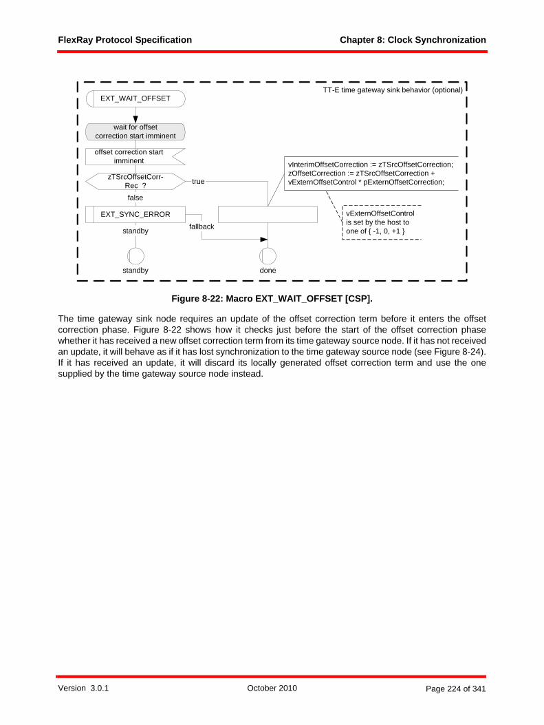
FlexRay Protocol Specification Chapter 8: Clock Synchronization
Figure 8-22: Macro EXT_WAIT_OFFSET [CSP].
The time gateway sink node requires an update of the offset correction term before it enters the offsetcorrection phase. Figure 8-22 shows how it checks just before the start of the offset correction phasewhether it has received a new offset correction term from its time gateway source node. If it has not receivedan update, it will behave as if it has lost synchronization to the time gateway source node (see Figure 8-24).If it has received an update, it will discard its locally generated offset correction term and use the onesupplied by the time gateway source node instead.
done
standby
wait for offsetcorrection start imminent
offset correction startimminent
zTSrcOffsetCorr-Rec ?false
fallback
vExternOffsetControlis set by the host toone of { -1, 0, +1 }
vInterimOffsetCorrection := zTSrcOffsetCorrection;zOffsetCorrection := zTSrcOffsetCorrection +vExternOffsetControl * pExternOffsetCorrection;true
EXT_SYNC_ERROR
EXT_WAIT_OFFSET
standby
TT-E time gateway sink behavior (optional)
Version 3.0.1 October 2010 Page 224 of 341

FlexRay Protocol Specification Chapter 8: Clock Synchronization
Figure 8-23: Macro EXT_WAIT_SYNC [CSP].
The time gateway sink node requires an update of the rate correction term before it enters a new even cycle.Figure 8-23 shows how it checks just before the start of the new even cycle whether it was provided with anew rate correction term by its time gateway source node. If it has not received such an update, it willbehave as if it has lost synchronization to the time gateway source node (see Figure 8-24).
If the time gateway sink node has received an update, it will discard its locally generated rate correction termand use the one supplied by the time gateway source node instead. In addition, if the zSyncExtern variableindicates that the time gateway source node is in POC:normal active the time gateway sink will set thevariable zRxStartupPairs to 2 - this allows the time gateway sink to follow the time gateway source as itmakes a transition from POC:normal passive to POC:normal active.
wait forcycle start imminent
cycle start imminent
vExternRateControl is set by the host to one of { -1, 0, +1 }
standby
odd
false
true
fallback
zTSrcSyncCalcResRec = trueand zTSrcRateCorrRec = true ?
vInterimRateCorrection := zTSrcRateCorrection;zRateCorrection := zTSrcRateCorrection + vExternRateControl * pExternRateCorrection;zSyncCalcResult := zTSrcSyncCalcResult;
EXT_SYNC_ERROR
vCycleCounter ?
evenzTSrcSyncCalc-
ResRec ?
true
EXT_WAIT_SYNC
even standby
EXT_SYNC_ERROR
false
odd
standby fallback
TT-E time gateway sink behavior (optional)
zSyncCalcResult := zTSrcSyncCalcResult;
zSyncExtern = ACTIVE ?
true
zRxStartupPairs := 2;
false
Version 3.0.1 October 2010 Page 225 of 341
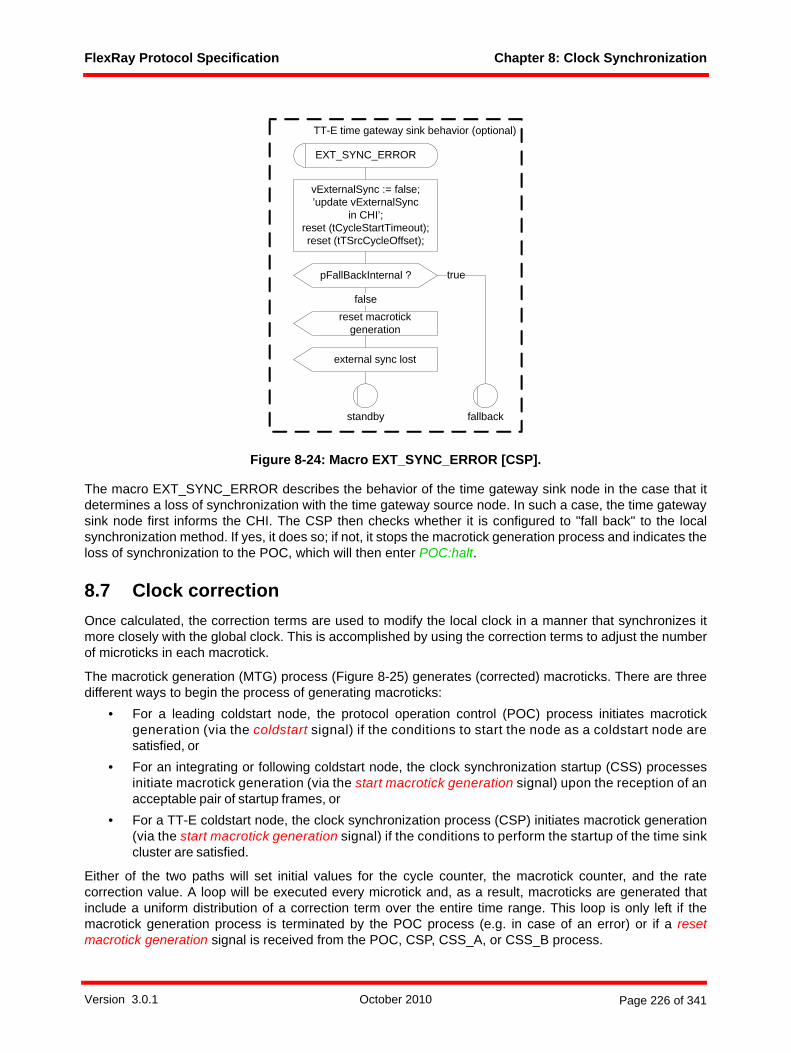
FlexRay Protocol Specification Chapter 8: Clock Synchronization
Figure 8-24: Macro EXT_SYNC_ERROR [CSP].
The macro EXT_SYNC_ERROR describes the behavior of the time gateway sink node in the case that itdetermines a loss of synchronization with the time gateway source node. In such a case, the time gatewaysink node first informs the CHI. The CSP then checks whether it is configured to "fall back" to the localsynchronization method. If yes, it does so; if not, it stops the macrotick generation process and indicates theloss of synchronization to the POC, which will then enter POC:halt.
8.7 Clock correctionOnce calculated, the correction terms are used to modify the local clock in a manner that synchronizes itmore closely with the global clock. This is accomplished by using the correction terms to adjust the numberof microticks in each macrotick.
The macrotick generation (MTG) process (Figure 8-25) generates (corrected) macroticks. There are threedifferent ways to begin the process of generating macroticks:
• For a leading coldstart node, the protocol operation control (POC) process initiates macrotickgeneration (via the coldstart signal) if the conditions to start the node as a coldstart node aresatisfied, or
• For an integrating or following coldstart node, the clock synchronization startup (CSS) processesinitiate macrotick generation (via the start macrotick generation signal) upon the reception of anacceptable pair of startup frames, or
• For a TT-E coldstart node, the clock synchronization process (CSP) initiates macrotick generation(via the start macrotick generation signal) if the conditions to perform the startup of the time sinkcluster are satisfied.
Either of the two paths will set initial values for the cycle counter, the macrotick counter, and the ratecorrection value. A loop will be executed every microtick and, as a result, macroticks are generated thatinclude a uniform distribution of a correction term over the entire time range. This loop is only left if themacrotick generation process is terminated by the POC process (e.g. in case of an error) or if a resetmacrotick generation signal is received from the POC, CSP, CSS_A, or CSS_B process.
pFallBackInternal ?
false
external sync lost
vExternalSync := false;’update vExternalSync
in CHI’;reset (tCycleStartTimeout);reset (tTSrcCycleOffset);
EXT_SYNC_ERROR
true
fallbackstandby
TT-E time gateway sink behavior (optional)
reset macrotick generation
Version 3.0.1 October 2010 Page 226 of 341
FlexRay Protocol Specification Chapter 8: Clock Synchronization
The relevant time range for the application of the rate correction term is the entire cycle; the time range forthe application of the offset correction term is the time between the start of the offset correction until the nextcycle start. The macrotick generation process handles this by two different initializations. At the cycle startthe algorithm is initialized using only the rate correction value; at the start of the offset correction phase thealgorithm is initialized again, this time including the offset correction values.
Concurrent with the MTG process new measurement values are taken by the CSP and these values areused to calculate new correction values. These new correction values are ultimately applied and used bythe macrotick generation process. The new offset correction value is applied at the start of offset correctionperiod in an odd communication cycle, and the new rate correction value is applied at the cycle start in aneven communication cycle.
Version 3.0.1 October 2010 Page 227 of 341

FlexRay Protocol Specification Chapter 8: Clock Synchronization
Figure 8-25: Macrotick generation [MTG].
zMicroDistribution ?else
<= 0vMacrotick := (vMacrotick + 1) mod gMacroPerCycle;
vMacrotick ? = pOffsetCorrectionStart
even
false
vMacrotick ?
vCycleCounter := (vCycleCounter +1) mod (gCycleCountMax + 1);
zIntegrationRound := false;
= 0
else
oscillator microtick clock
vCycleCounter ?
macrotick (vMacrotick)
wait for microtick
else
initialize offset correction
initialize rate correction
wait for start
start macrotick generation (vCycle-Counter, vMacrotick, zRateCorr)coldstart
vMacrotick := gMacroPerCycle - gdStaticSlot; zRateCorr := 0; vCycleCounter := gCycleCountMax;zIntegrationRound := true;
reset macrotick generation
offset calc ready (zOffsetCorr)
dcl zIntegrationRound Boolean;dcl zMicroPerPeriod T_Microtick;dcl zMacroPerPeriod T_Macrotick;dcl zMicroDistribution T_Microtick;dcl zRateCorrection T_Deviation := 0;dcl vMacrotick T_Macrotick;dcl vMicrotick T_Microtick := 0;dcl vCycleCounter T_CycleCounter;dcl zRateCorr T_Deviation := 0;dcl zOffsetCorr T_Deviation := 0;
macrotick (vMacrotick)
zIntegrationRound := true;
zIntegrationRound := true;
zIntegrationRound ?true
false
zIntegrationRound := false;
start macrotick generation (vCycle-Counter, vMacrotick, zRateCorr)
’update vMacrotick in CHI’;
wait for startrate calc ready (zRateCorr)
vMacrotick ?
= 0
else
’update vMacrotick, vCycleCounter in CHI’;
zMicroDistribution := zMicroDistribution + zMicroPerPeriod;
zMicroDistribution := 0;zMicroPerPeriod := pMicroPerCycle + zRateCorrection - vMicrotick + zOffsetCorr; zMacroPerPeriod := gMacroPerCycle - pOffsetCorrectionStart;
vMicrotick := vMicrotick + 1;zMicroDistribution := zMicroDistribution - zMacroPerPeriod;
macrotick (vMacrotick),EXP cycle start (vCycleCounter)
zRateCorrection := zRateCorr;zMicroPerPeriod := pMicroPerCycle + zRateCorrection;zMacroPerPeriod := gMacroPerCycle;zMicroDistribution := 0;vMicrotick := 0;zOffsetCorr := 0;
GENERATE_IMMI-NENT
pExternalSync ?
odd
true
Version 3.0.1 October 2010 Page 228 of 341
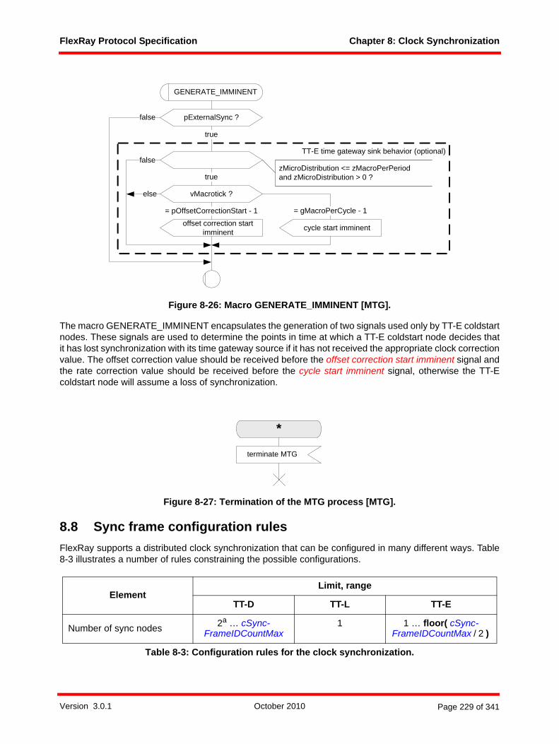
FlexRay Protocol Specification Chapter 8: Clock Synchronization
Figure 8-26: Macro GENERATE_IMMINENT [MTG].
The macro GENERATE_IMMINENT encapsulates the generation of two signals used only by TT-E coldstartnodes. These signals are used to determine the points in time at which a TT-E coldstart node decides thatit has lost synchronization with its time gateway source if it has not received the appropriate clock correctionvalue. The offset correction value should be received before the offset correction start imminent signal andthe rate correction value should be received before the cycle start imminent signal, otherwise the TT-Ecoldstart node will assume a loss of synchronization.
Figure 8-27: Termination of the MTG process [MTG].
8.8 Sync frame configuration rulesFlexRay supports a distributed clock synchronization that can be configured in many different ways. Table8-3 illustrates a number of rules constraining the possible configurations.
ElementLimit, range
TT-D TT-L TT-E
Number of sync nodes 2a … cSync-FrameIDCountMax
1 1 … floor( cSync-FrameIDCountMax / 2 )
Table 8-3: Configuration rules for the clock synchronization.
GENERATE_IMMINENT
true
false
true
vMacrotick ?
= pOffsetCorrectionStart - 1 = gMacroPerCycle - 1
else
offset correction start imminent cycle start imminent
pExternalSync ?
TT-E time gateway sink behavior (optional)
false
zMicroDistribution <= zMacroPerPeriod and zMicroDistribution > 0 ?
*
terminate MTG
Version 3.0.1 October 2010 Page 229 of 341

FlexRay Protocol Specification Chapter 8: Clock Synchronization
8.8.1 TT-D clusterA TT-D cluster consists of a number of sync nodes and an arbitrary number of non-sync nodes. Eachcoldstart node is always a sync node but there can be more sync nodes than coldstart nodes. A number ofnodes must be configured as sync nodes depending on the following rules:
• At least two nodes shall be configured to be sync nodes.• At least two of the sync nodes must also be TT-D coldstart nodes.• At most cSyncFrameIDCountMax nodes shall be configured to be sync nodes.• Only nodes with pChannels = gChannels may be sync nodes (i.e., sync nodes must be connected
to all configured channels).• Sync nodes that support two channels shall send two sync frames in the static segment, one on
each channel in the corresponding slot with the slot number which equals pKeySlotID.122 Syncnodes that only support a single channel shall send one sync frame in the static segment. The syncframe shall be sent in the slot with the slot number which equals pKeySlotID.
• The sync frames shall be sent in all slots with the same slot number, i.e. in each cycle.• Non-sync nodes must not transmit frames with the sync frame indicator set to one.
8.8.2 TT-E clusterA TT-E cluster consists only of coldstart nodes and an arbitrary number of non-sync nodes. In that respectthe following rules must be observed:
• At least one node shall be configured to be a sync node.• Each sync node must also be a TT-E coldstart node.• At most cSyncFrameIDCountMax / 2 nodes shall be configured to be sync nodes.• Only nodes with pChannels = gChannels may be sync nodes (i.e., sync nodes must be connected
to all configured channels).• Sync nodes that support two channels shall send four sync frames in the static segment, two on
each channel, in the slots with slot number equal to pKeySlotID or pSecondKeySlotID.123 Syncnodes that support only a single channel shall send two sync frames in the static segment in theslots with slot number equal to pKeySlotID or pSecondKeySlotID.
• The sync frames shall be sent in all slots with the same slot number, i.e. in each cycle.• Non-sync nodes must not transmit frames with the sync frame indicator set to one.
8.8.3 TT-L clusterA TT-L cluster consists only of a single coldstart node and an arbitrary number of non-sync nodes. In thatrespect the following rules must be observed:
Number of sync frame ID's = number of sync nodes
2 = 2 * number of sync nodes
Number of static slots >= number of sync frame ID's
>= 2 >= number of sync frame ID's
a. A TT-D cluster with only two sync nodes (each of which is also configured to be a coldstart node) would be able to start up and continue to operate, but a loss of either of the two sync nodes would result in the loss of all communication.
122 The frames sent on the two channels in these slots do not need to be identical (i.e., they may have differing payloads), but they must both be sync frames.
123 The frames sent in these slots by a TT-E sync node do not need to be identical (i.e., different payloads may be sent on each channel, or in each of the key slots), but all must be sync frames.
Table 8-3: Configuration rules for the clock synchronization.
Version 3.0.1 October 2010 Page 230 of 341
FlexRay Protocol Specification Chapter 8: Clock Synchronization
• A single node shall be configured to be a sync node.• The single sync node must be a TT-L coldstart node.• Only nodes with pChannels = gChannels may be sync nodes (i.e., sync nodes must be connected
to all configured channels).• Sync nodes that support two channels shall send four sync frames in the static segment, two on
each channel, in the slots with slot number equal to pKeySlotID or pSecondKeySlotID.124 Syncnodes that support only a single channel shall send two sync frames in the static segment in theslots with slot number equal to pKeySlotID or pSecondKeySlotID.
• The sync frames shall be sent in all slots with the same slot number, i.e. in each cycle.• Non-sync nodes must not transmit frames with the sync frame indicator set to one.
8.9 Time gateway interfaceThe time gateway interface connects two communication controllers. It provides information about theschedule of the time gateway source node to the time gateway sink node.
The signals to be provided by the time gateway source node are marked in the SDL description using theEXP keyword. The signals in question are
• cycle startThis signal is used by the time gateway sink node to initialize its own schedule and later on tomonitor if it still operates synchronously to the time gateway source node.
• sync stateThis signal is used by the time gateway sink node to determine if the time gateway source node is inPOC:normal active, POC:normal passive or a different state.
• offset calc readyThis signal is used by the time gateway sink node to perform the same clock offset correction as thetime gateway source node.
• rate calc readyThis signal is used by the time gateway sink node to perform the same clock rate correction as thetime gateway source node.
• SyncCalcResultThis signal is used by the time gateway sink node to determine if the time gateway source nodemaintains synchronization with the time source cluster.
The fixed offset of cdTSrcCycleOffset microticks between the schedule of the time gateway source nodeand the time gateway sink node ensures that each transferred piece of information arrives in time to beproperly used by the time gateway sink node.
124 The frames sent in these slots by a TT-L sync node do not need to be identical (i.e., different payloads may be sent on each channel, or in each of the key slots), but all must be sync frames.
Version 3.0.1 October 2010 Page 231 of 341
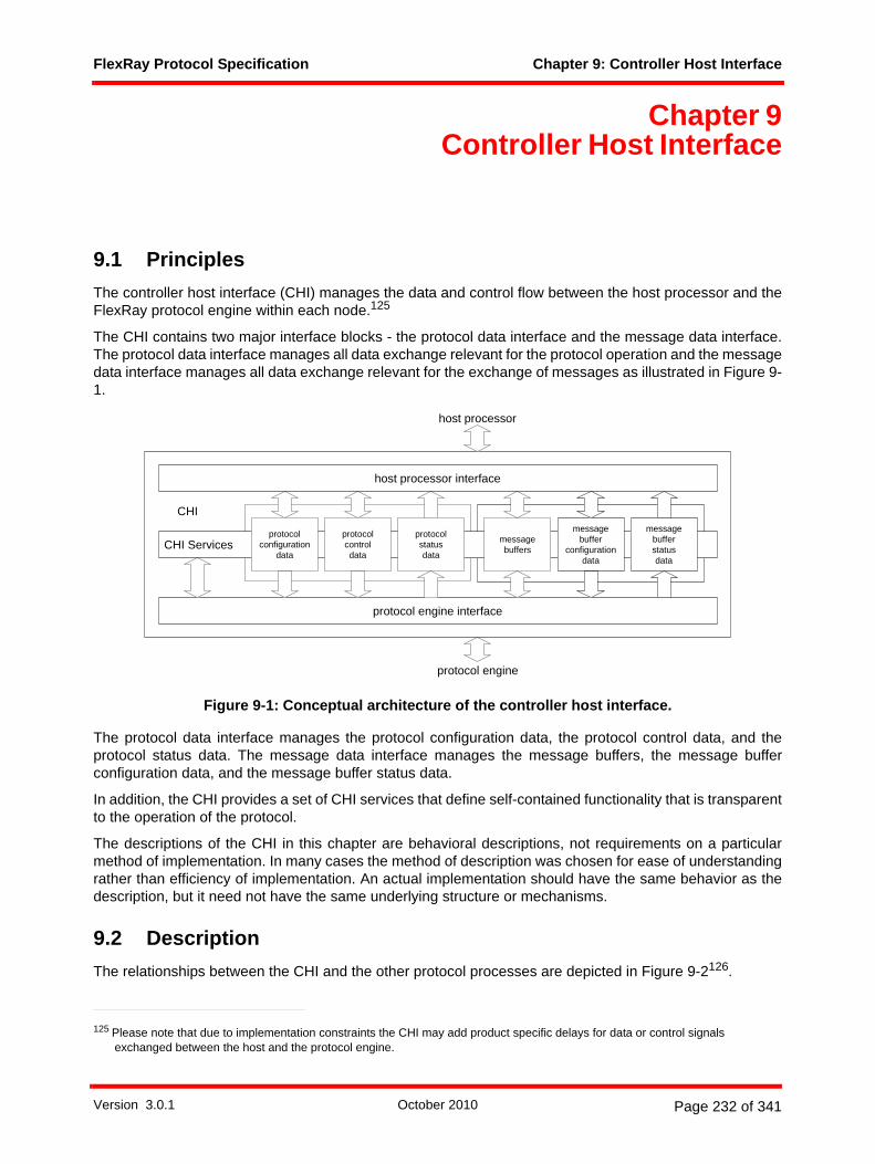
FlexRay Protocol Specification Chapter 9: Controller Host Interface
Chapter 9Controller Host Interface
9.1 PrinciplesThe controller host interface (CHI) manages the data and control flow between the host processor and theFlexRay protocol engine within each node.125
The CHI contains two major interface blocks - the protocol data interface and the message data interface.The protocol data interface manages all data exchange relevant for the protocol operation and the messagedata interface manages all data exchange relevant for the exchange of messages as illustrated in Figure 9-1.
Figure 9-1: Conceptual architecture of the controller host interface.
The protocol data interface manages the protocol configuration data, the protocol control data, and theprotocol status data. The message data interface manages the message buffers, the message bufferconfiguration data, and the message buffer status data.
In addition, the CHI provides a set of CHI services that define self-contained functionality that is transparentto the operation of the protocol.
The descriptions of the CHI in this chapter are behavioral descriptions, not requirements on a particularmethod of implementation. In many cases the method of description was chosen for ease of understandingrather than efficiency of implementation. An actual implementation should have the same behavior as thedescription, but it need not have the same underlying structure or mechanisms.
9.2 DescriptionThe relationships between the CHI and the other protocol processes are depicted in Figure 9-2126.
125 Please note that due to implementation constraints the CHI may add product specific delays for data or control signals exchanged between the host and the protocol engine.
host processor
protocol engine
CHI Servicesprotocol
configurationdata
host processor interface
protocol engine interface
CHI
protocolcontroldata
protocolstatusdata
messagebuffer
configurationdata
messagebuffers
messagebufferstatusdata
Version 3.0.1 October 2010 Page 232 of 341

FlexRay Protocol Specification Chapter 9: Controller Host Interface
Figure 9-2: Controller host interface context.
9.3 Interfaces 9.3.1 Protocol data interface
9.3.1.1 Protocol configuration dataThe host shall have write access to protocol configuration data only when the protocol is in the POC:configstate.
The host shall have read access to protocol configuration data regardless of the protocol state.
126 The dark lines represent data flows between mechanisms that are relevant to this chapter. The lighter gray lines are relevant to the protocol, but not to this chapter.
frame and symbolprocessing
media accesscontrol
clocksynchronization
startup
macrotickgeneration
clocksynchronization
processing
protocoloperation
control
controllerhost interface
coding / decodingprocesseschannel A
frame and symbolprocessingchannel A
media accesscontrol
channel A
clocksynchronization
startup channel A
to channel interface from channel interface
to / from host
mediaaccesscontrolchannel B
coding / decodingprocesseschannel B
frame andsymbolprocessingchannel B
clocksynchronization
startupchannel B
Version 3.0.1 October 2010 Page 233 of 341
FlexRay Protocol Specification Chapter 9: Controller Host Interface
9.3.1.1.1 Communication cycle timing configurationAll configuration data relating to the following communication cycle timing parameters shall be treated asprotocol configuration data:
1. the number of microticks pMicroPerCycle constituting the duration of the communication cycle,2. the number of macroticks gMacroPerCycle within a communication cycle,3. the number of static slots gNumberOfStaticSlots in the static segment,4. the number of macroticks gdStaticSlot constituting the duration of a static slot within the static seg-
ment,5. the number of macroticks gdActionPointOffset constituting the offset of the action point within static
slots,6. the number of macroticks gdMinislot constituting the duration of a minislot,7. the number of minislots gNumberOfMinislots within the dynamic segment,8. the number of macroticks gdMinislotActionPointOffset constituting the offset of the action point within a
minislot of the dynamic slot,9. the number of minislots gdDynamicSlotIdlePhase constituting the duration of the idle phase within a
dynamic slot,10. the number of the last minislot pLatestTx in which transmission can start in the dynamic segment,11. the number of macroticks gdSymbolWindow constituting the duration of the symbol window, 12. the number of macroticks gdSymbolWindowActionPointOffset constituting the offset of the action point
within the symbol window,
13. the cycle number gCycleCountMax after which the cycle counter is reset back to zero127.
In addition to the above, an implementation shall allow a system designer control over the parametersgdSampleClockPeriod and pSamplesPerMicrotick. These parameters need not be directly implemented,but may instead be derived from other parameters not explicitly defined in this specification. For example,gdSampleClockPeriod may be derived from parameters that set the prescalers, phase-locked loop multi-pliers, etc. for an implementation's sample clock and the designer's knowledge of the design frequency ofthe underlying clocks. As a result, there is no specific requirement to be able to read or configure these exactparameters, but there is a requirement for a system designer to be able to control their values, i.e., to controlthe period of the sample clock and the duration of the microtick to allow the values for those quantitiesrequired by the specification.
9.3.1.1.2 Protocol operation configurationAll configuration data relating to the following protocol operation parameters shall be treated as protocolconfiguration data:
1. the number of consecutive even/odd cycle pairs with missing clock correction terms gMaxWithout-ClockCorrectionFatal that will cause the protocol to transition from the POC:normal active or POC:nor-mal passive state into the POC:halt state,
2. the number of consecutive even/odd cycle pairs with missing clock correction terms gMaxWithout-ClockCorrectionPassive that will cause the protocol to transition from the POC:normal active to the POC:normal passive state,
3. the number of microticks pClusterDriftDamping constituting the cluster drift damping factor used for rate correction within clock synchronization,
4. the number of macroticks pOffsetCorrectionStart between the start of the communication cycle and the start of the offset correction within the NIT,
127 The cycle counter will return to the same value after gCycleCountMax + 1 cycles.
Version 3.0.1 October 2010 Page 234 of 341

FlexRay Protocol Specification Chapter 9: Controller Host Interface
5. the number of microticks pExternOffsetCorrection constituting the correction term used to correct the calculated offset correction value in the course of external clock synchronization,
6. the number of microticks pExternRateCorrection constituting the correction term used to correct the calculated rate correction value in the course of external clock synchronization,
7. the number of microticks pOffsetCorrectionOut constituting the upper bound for a permissible offset correction,
8. the number of microticks pRateCorrectionOut constituting the upper bound for a permissible rate cor-rection and the maximum drift offset between two nodes operating with non-synchronized clocks for one communication cycle,
9. the Boolean parameter pAllowHaltDueToClock that controls the transition to the POC:halt state due to a clock synchronization error,
10. the number of consecutive even/odd cycle pairs pAllowPassiveToActive during which valid clock syn-chronization terms must be received before the node transitions from the POC:normal passive state to the POC:normal active state, including the configuration data to disable transitions from the POC:nor-mal passive state to the POC:normal active state,
11. the Boolean parameter pKeySlotOnlyEnabled that defines whether, after completing startup, a node is restricted to send only in its keyslots or is allowed to transmit in all assigned slots,
12. the Boolean parameter pKeySlotUsedForStartup that defines whether the specific node shall send startup frames,
13. the Boolean parameter pKeySlotUsedForSync that defines whether the specific node shall send sync frames,
14. the slot ID of the key slot, pKeySlotID. A node that does not have a key slot would configure pKey-SlotID to zero (a value which will never match any actual static slot ID). The effect of such a zero con-figuration for pKeySlotID is that no static slot has the characteristics of the key slot (and thus the node, in effect, does not have a key slot). The key slot, if the node has one, must be assigned to the node by the CHI in all cycles. In particular, the slot ID indicated by a non-zero configuration of pKeySlotID is assigned to the node (in the sense that for that slot the variable vTCHI!Assignment is set to ASSIGNED) on all configured channels in all communication cycles,
15. the slot ID of the second key slot, pSecondKeySlotID in which a second startup frame shall be sent when operating as coldstart node in a TT-L or TT-E cluster,
16. the number of microticks pDecodingCorrection used by the node to calculate the primary time refer-ence point,
17. the enumeration pChannels that indicates the channels to which the node is connected. The configura-tion of channels supported by the device, pChannels, has a unique characteristic in that it may affect significant hardware details of the implementation. Dual channel devices must be able to support sin-gle channel operation and single channel devices must be configurable to work on either channel A or channel B. As a result, it is required that an implementation be able to configure pChannels, but the ability to configure this more than once while the CC is in the power on state (see section 2.1.1) is not required. This mechanism does not need to be available in POC:config. A device may not, however, allow this parameter to be modified in the POC:ready, POC:normal active, POC:normal passive, or POC:halt states, or in any of the states that are defined in the WAKEUP and STARTUP macros of the POC process,
18. the maximum number of consecutive low bits gdCASRxLowMax which the node would accept as a valid CAS symbol,
19. the number of bits gdIgnoreAfterTx for which bit strobing is paused after a transmission, 20. the number of microticks pDelayCompensation[A] used to include the channel A specific reception
delay in the calculation of the primary time reference point, 21. the number of microticks pDelayCompensation[B] used to include the channel B specific reception
delay in the calculation of the primary time reference point,
Version 3.0.1 October 2010 Page 235 of 341

FlexRay Protocol Specification Chapter 9: Controller Host Interface
22. the number of two-byte words gPayloadLengthStatic contained in the payload segment of a static frame,
23. the number of bits gdTSSTransmitter within the transmission start sequence.24. the maximum number gSyncFrameIDCountMax of distinct sync frame identifiers that may be present
in a given cluster,
25. the optional128 Boolean parameter pFallBackInternal that defines whether a time gateway sink node will switch to local clock operation when synchronization with the time gateway source node is lost (pFallBackInternal = true) or will instead go to POC:halt (pFallBackInternal = false),129
26. the optional130 Boolean parameter pExternalSync that defines whether the node begins operation131 with the clock synchronization externally synchronized (pExternalSync = true) or not externally syn-chronized (pExternalSync = false),
27. the Boolean parameter pTwoKeySlotMode that defines whether the node operates as a coldstart node in a TT-E or TT-L cluster.
9.3.1.1.3 Wakeup and startup configurationAll configuration data relating to the following wakeup and startup parameters shall be treated as protocolconfiguration data:
1. the number of bits gdWakeupRxIdle used by the node to test the duration of the received idle or ’active high’ parts of a wakeup,
2. the number of bits gdWakeupRxLow used by the node to test the duration of the received ’active low’ parts of a wakeup,
3. the number of bits gdWakeupRxWindow used by the node to test the duration of a received wakeup,4. the number of bits gdWakeupTxIdle used by the node to transmit the idle part of the wakeup symbol,5. the number of bits gdWakeupTxActive used by the node to transmit the ’active low’ part of the wakeup
symbol and the ’active low’ and ’active high’ parts of a WUDOP,6. the number of wakeup symbols pWakeupPattern to be sent by the node to create a wakeup pattern, 7. the enumeration pWakeupChannel that indicates on which channel a wakeup symbol shall be sent
upon issuing the WAKEUP command,8. the number of macroticks pMacroInitialOffset[A] between a static slot boundary and the subsequent
macrotick boundary of the secondary time reference point based on the nominal macrotick duration,9. the number of macroticks pMacroInitialOffset[B] between a static slot boundary and the subsequent
macrotick boundary of the secondary time reference point based on the nominal macrotick duration,10. the number of microticks pMicroInitialOffset[A] between the secondary time reference point on channel
A and the macrotick boundary immediately following the secondary time reference point,11. the number of microticks pMicroInitialOffset[B] between the secondary time reference point on channel
B and the macrotick boundary immediately following the secondary time reference point,12. the number of microticks pdAcceptedStartupRange constituting the expanded range of measured
deviation for startup frames during integration,13. the number of microticks pdListenTimeout constituting the upper limit for the startup and wakeup listen
timeout,14. the maximum number of times gColdstartAttempts that a node is permitted to attempt to start the clus-
ter by initiating schedule synchronization,
128 The Boolean parameter is only required in implementations that implement a time gateway sink.129 This parameter shall not be set to true if the cluster contains more than one TT-E coldstart node.130 The Boolean parameter is only required in implementations that implement a time gateway sink.131 Note that it is possible that the actual synchronization mode of the cluster (as represented by the variable vExternalSync)
can change from externally synchronized to not externally synchronized during the operation of the cluster.
Version 3.0.1 October 2010 Page 236 of 341
FlexRay Protocol Specification Chapter 9: Controller Host Interface
15. the upper limit gListenNoise of the number of startup and wakeup listen timeouts in the presence of noise.
9.3.1.1.4 Network Management Vector configurationAll configuration data relating to the following Network Management Vector parameters shall be treated asprotocol configuration data:
1. the number of bytes gNetworkManagementVectorLength contained in the network management vec-tor,
2. the Boolean parameter pNMVectorEarlyUpdate that defines the segment after which the accrued net-work management vector is exported to the CHI.
9.3.1.2 Protocol control data
9.3.1.2.1 Control of the protocol operation controlThe CHI shall provide means for the host to send the following protocol control commands to the POCprocess of the protocol. The conditions under which these commands will be acted upon or ignored aredefined in Chapter 9 and Table 2-1:132
1. an ALLOW_COLDSTART command that activates the capability of the node to coldstart the cluster,2. an ALL_SLOTS command that controls the transition from the key slot only mode to the all slots trans-
mission mode,3. a CONFIG command that causes a transition of the POC process from either the POC:default config
state or the POC:ready state to the POC:config state,4. a CONFIG_COMPLETE command that causes a transition of the POC process from the POC:config
state to the POC:ready state,5. a FREEZE command that causes a transition of the POC process from any POC state to the POC:halt
state,6. an IMMEDIATE_READY command that causes an immediate transition of the POC process to the
POC:ready state,7. a RUN command that initiates the startup procedure,8. a DEFAULT_CONFIG command that causes a transition of the POC process from the POC:halt state
to the POC:default config state,9. a DEFERRED_HALT command that causes a transition of the POC to the POC:halt state,10. a WAKEUP command that initiates the wakeup procedure,11. a DEFERRED_READY command that causes a transition of the POC process to the POC:ready state
from all states except POC:default config, POC:config, POC:ready, POC:halt,12. a CLEAR_DEFERRED command that removes any pending DEFERRED_READY or
DEFERRED_HALT command.
9.3.1.2.2 Control of MTS and WUDOP transmissionThe CHI shall provide means for the host
1. To control the transmission of MTS symbols on channel A within the symbol window. To perform this the CHI interacts with the protocol engine via the variable vTransmitMTS_A (as defined within the MAC_A process),
132 The CHI does not buffer host commands and issue them to the POC at a later time – they are essentially passed “immediately” to the POC process.
Version 3.0.1 October 2010 Page 237 of 341

FlexRay Protocol Specification Chapter 9: Controller Host Interface
2. To control the transmission of MTS symbols on channel B within the symbol window. To perform this the CHI interacts with the protocol engine via the variable vTransmitMTS_B (as defined within the MAC_B process),
3. To control the transmission of WUDOPs on channel A within the symbol window. To perform this the CHI interacts with the protocol engine via the variable vTransmitWUDOP_A133 (as defined within the MAC_A process),
4. To control the transmission of WUDOPs on channel B within the symbol window. To perform this the CHI interacts with the protocol engine via the variable vTransmitWUDOP_B (as defined within the MAC_B process).
The control of MTS transmission shall support, at a minimum, the ability of the host to request a single MTStransmission (i.e., a "one-shot" or manual MTS request).
The control of the WUDOP transmission shall support the ability of the host to request a single WUDOPtransmission (i.e., a "one-shot" or manual WUDOP request), but shall also support an automatic request bywhich the host can identify a set of FlexRay communication cycles in which the CC will transmit a WUDOPin the symbol window without additional host interaction. This automatic mechanism shall operate inaddition to the manual mechanism (i.e., a WUDOP should be sent if either the manual or automatic mecha-nisms, or both, indicate that a WUDOP should be sent).
The configuration of the specific cycles in which the automatic transmission of WUDOPs takes place shallsupport, at a minimum, the ability to define sets of communication cycles which equal the sets which can bedefined using a Cycle_Repetition and a Cycle_Offset to determine the configuration:
Automatically transmit a WUDOP in the symbol window if vCycleCounter mod Cycle_Repetition = Cycle_Offset
with Cycle_Repetition selected from the set of {1, 2, 4, 5, 8, 10, 16, 20, 32, 40, 50, 64}134 Cycle_Offset selected from the set {0 … 63} with Cycle_Offset < Cycle_Repetition
It is not required that an implementation supports independent sets of repetition and offset parameters foreach channel (i.e., a single set of parameters controlling automatic WUDOP generation for both channelsis acceptable). It is acceptable, but not required, that the repetition and offset parameters controllingautomatic WUDOP generation be modifiable during operation (i.e., when the node is in the POC:normalactive state). It is required, however, that automatic WUDOP generation be independently controllable (i.e.,switched on or off) on a per channel basis when the node is in the POC:normal active state.135
A transition into the POC:ready state shall cause the CHI to reset any pending one-shot transmissions ofWUDOP's or MTS's.136
Transmissions in the symbol window must be coordinated at a system level, i.e., the system designer mustensure for each channel that in any given cycle at most one node will transmit either an MTS or a WUDOPin the symbol window on that channel.
9.3.1.2.3 Control of external clock synchronizationThe CHI shall provide means for the host
133 This variable represents the control value of both the automatic and manual mechanisms for WUDOP transmission.134 Note that these particular values of Cycle_Repetition are those that could be achieved by combining a "power of 2" filter with
a "count to 5" filter.135 It is also allowable that automatic WUDOP generation can be switched on or off in other POC states, but the actual
generation of WUDOPs will only take place when the node is in the POC:normal active state.136 This prevents unintentional WUDOP or MTS transmissions left over from previous operation for TT-E coldstart nodes (for
example, if an IMMEDIATE_READY command is followed by a RUN command).
Version 3.0.1 October 2010 Page 238 of 341

FlexRay Protocol Specification Chapter 9: Controller Host Interface
1. to control the application of the external offset correction parameter pExternOffsetCorrection using the control value vExternOffsetControl,
2. to control the application of the external rate correction parameter pExternRateCorrection using the control value vExternRateControl.
A transition into the POC:ready state shall cause the CHI to set the variables that control the operation ofthe external rate and offset correction (i.e., vExternRateControl and vExternOffsetControl) such that noexternal rate or offset correction is requested.
9.3.1.3 Protocol status dataThe CHI shall provide the protocol status information described in the following subsections.
The following subsections define a number of indicators. These indicators are a type of status informationthat can take on two distinct values, labeled as "set" and "reset". An indicator is set (i.e., given the "set"value) by the CHI when certain events occur in the execution of the protocol, and are, in general, reset (i.e.,given the "reset" value) by the host.
An implementation shall ensure that each indicator described in the following subsections is reset under atleast one of the following conditions:
• every transition into the POC:default config state• every transition into the POC:config state• every transition out of the POC:config state.
The specific behavior of an implementation with respect to the reset behavior of each indication is imple-mentation dependent.
9.3.1.3.1 Protocol operation control statusThe following protocol operation control status variables shall be provided in the CHI:
1. the status variable vPOC!State (as maintained by the POC process),2. the flag vPOC!Freeze (as maintained by the POC process),3. the flag vPOC!CHIReadyRequest (as maintained by the POC process),4. the flag vPOC!CHIHaltRequest (as maintained by the POC process),5. the flag vPOC!ColdstartNoise (as maintained by the POC process),6. the status variable vPOC!SlotMode (as maintained by the POC process),7. the status variable vPOC!ErrorMode (as maintained by the POC process),8. the number of consecutive even/odd cycle pairs vAllowPassiveToActive that have passed with valid
rate and offset correction terms, but with the node still in POC:normal passive state due to a host con-figured delay to POC:normal active state (as maintained by the POC process),
9. the status variable vPOC!WakeupStatus (as maintained by the POC process), 10. the status variable vPOC!StartupState (as maintained by the POC process),
11. the optional137 flag vExternalSync (as maintained by the CSP process).
9.3.1.3.2 Wakeup and startup statusThe following startup status variable shall be provided in the CHI:
1. the number of remaining coldstart attempts vRemainingColdstartAttempts (as maintained by the POC process).
The CHI shall provide indicators for the following wakeup and startup events:
137 The status variable is only required in implementations that implement a time gateway sink.
Version 3.0.1 October 2010 Page 239 of 341
FlexRay Protocol Specification Chapter 9: Controller Host Interface
1. a coldstart abort indicator that shall be set upon 'set coldstart abort indicator in CHI' (in accordance with the POC process) and reset under control of the host,
2. a wakeup pattern received indicator for channel A that shall be set upon 'set wakeup received indicator on A in CHI' (in accordance with the FSP_A process) and reset under control of the host,
3. a wakeup pattern received indicator for channel B that shall be set upon 'set wakeup received indicator on B in CHI' (in accordance with the FSP_B process) and reset under control of the host.
9.3.1.3.3 Communication cycle timing statusThe following communication cycle timing variables shall be provided in the CHI:
1. the macrotick vMacrotick (as maintained by the MTG process),2. the cycle counter vCycleCounter (as maintained by the MTG process),3. the slot counter vSlotCounter for channel A (as maintained by the MAC_A process),4. the slot counter vSlotCounter for channel B (as maintained by the MAC_B process).
The values provided to the host by the CHI for vMacrotick, vCycleCounter and vSlotCounter for channel Aand B shall be valid during the states POC:normal active and POC:normal passive.
A snapshot of the following communication cycle timing variables shall be provided in the CHI:
1. the rate correction value vInterimRateCorrection (in accordance with the CSP process).• If vExternalSync138 is false the rate correction value is based on the internally calculated values, is
not limited by pRateCorrectionOut, and does not include any external rate correction value. • If vExternalSync is true the rate correction value is imported from the time gateway source and
includes the limitation and external rate correction values as configured in the time gateway source. 2. the offset correction value vInterimOffsetCorrection (as maintained by the CSP process).
• If vExternalSync is false the offset correction value is based on the internally calculated values, isnot limited with pOffsetCorrectionOut, and does not include any external offset correction value.
• If vExternalSync is true the offset correction value is imported from the time gateway source andincludes the limitation and external offset correction values as configured in the time gatewaysource.
The CHI shall provide indicators for the following communication cycle timing events:
1. a sync frame overflow indicator that shall be set upon 'set sync frame overflow indicator in CHI' (in accordance with the CSP process) and reset under control of the host,
2. a pLatestTx violation status indicator for channel A that shall be set upon 'set pLatestTx violation sta-tus indicator on A in CHI' (in accordance with the MAC_A process), and reset under control of the host,
3. a pLatestTx violation status indicator for channel B that shall be set upon 'set pLatestTx violation sta-tus indicator on B in CHI' (in accordance with the MAC_B process), and reset under control of the host,
4. a transmission across boundary violation status indicator for channel A that shall be set upon 'set transmission across slot boundary violation indicator on A in CHI' (in accordance with the FSP_A proc-ess),
5. a transmission across boundary violation status indicator for channel B that shall be set upon 'set transmission across slot boundary violation indicator on B in CHI' (in accordance with the FSP_B proc-ess).
138 If the optional flag vExternalSync does not exist the communication controller shall behave as if vExternalSync is equal to false. Refer to section 1.10.3.
Version 3.0.1 October 2010 Page 240 of 341
FlexRay Protocol Specification Chapter 9: Controller Host Interface
9.3.1.3.4 Synchronization frame statusA snapshot of the following information, derived from the vsSyncIDListA and vsSyncIDListB variablesprovided by the CSP process, shall be provided in the CHI:
1. A list containing the IDs of the sync frames received or transmitted on channel A within the even com-munication cycle as well as the number of valid entries contained in this list,
2. A list containing the IDs of the sync frames received or transmitted on channel B within the even com-munication cycle as well as the number of valid entries contained in this list,
3. A list containing the IDs of the sync frames received or transmitted on channel A within the odd com-munication cycle as well as the number of valid entries contained in this list,
4. A list containing the IDs of the sync frames received or transmitted on channel B within the odd com-munication cycle as well as the number of valid entries contained in this list.
The information shall be updated no sooner than the start of the NIT and no later than 10 macroticks afterthe start of the offset correction phase of the NIT. Note that this implies that for some NIT configurations thedata update may complete after the start of the next cycle.
The following synchronization frame variable shall be provided in the CHI:
1. the number of consecutive even/odd cycle pairs vClockCorrectionFailed that have passed without clock synchronization having performed an offset or a rate correction due to lack of synchronization frames (as maintained by the POC process).
9.3.1.3.5 Startup frame statusA snapshot of the following information, derived from the vStartupPairs variable provided by the CSPprocess, shall be provided in the CHI:
1. the number of channel aligned startup frame pairs received or transmitted during the previous double cycle, aggregated across both channels.
The availability of this information depends on the synchronization method and role of the node in thecluster. For TT-E coldstart nodes the information shall be updated no sooner than one microtick before theend of the NIT in the odd cycle and no later than 10 macroticks after the start of the next cycle. For all othernodes the information shall be updated no sooner than the start of the NIT in the odd cycle and no later than10 macroticks after the start of the offset correction phase of the NIT. Note that this implies that for someNIT configurations the data update may complete after the start of the next cycle.
9.3.1.3.6 Symbol window statusA snapshot of the following symbol window variables shall be provided in the CHI for the slot status vSSestablished for each channel at the end of the symbol window:
1. the flag vSS!ValidMTS for channel A (in accordance with the FSP_A process),2. the flag vSS!ValidMTS for channel B (in accordance with the FSP_B process),3. the flag vSS!SyntaxError for channel A (in accordance with the FSP_A process),4. the flag vSS!SyntaxError for channel B (in accordance with the FSP_B process),5. the flag vSS!BViolation for channel A (in accordance with the FSP_A process),6. the flag vSS!BViolation for channel B (in accordance with the FSP_B process),7. the flag vSS!TxConflict for channel A (in accordance with the FSP_A process),8. the flag vSS!TxConflict for channel B (in accordance with the FSP_B process).
The following list indicates the behavior of the CHI depending on the activities detected on the RxD input:• The low phases of a WUDOP might cause an indication of a valid MTS even if only a WUDOP was
actually present. This may or may not happen (depending on the data rate, which affects theduration of what is accepted as a valid MTS).
Version 3.0.1 October 2010 Page 241 of 341

FlexRay Protocol Specification Chapter 9: Controller Host Interface
• Because the low phases of a WUDOP can be considered as a valid MTS, the reception of multiplevalid MTS's within a symbol window is not indicated as a syntax error.
• Although the WUDOP is transmitted in the symbol window, an indication that a wakeup has beenreceived may not occur until sometime during the NIT (i.e., the symbol window status may becomeavailable to the host before the indication that a wakeup has been received becomes available tothe host).
• In the normal situation, the reception of an MTS or WUDOP will not result in boundary violations orsyntax errors (i.e., those conditions represent exceptional circumstances such as additionalcommunication elements, noise on the link, etc.).
• It is possible to detect a valid MTS, or to detect a wakeup, even in the presence of syntax errors orboundary violations.
9.3.1.3.7 NIT statusA snapshot of the following NIT variables shall be provided in the CHI for the slot status vSS established foreach channel at the end of the NIT:
1. the flag vSS!SyntaxError for channel A (in accordance with the FSP_A process),2. the flag vSS!SyntaxError for channel B (in accordance with the FSP_B process),3. the flag vSS!BViolation for channel A (in accordance with the FSP_A process),4. the flag vSS!BViolation for channel B (in accordance with the FSP_B process).
9.3.1.3.8 Aggregated channel statusThe aggregated channel status provides the host with an accrued status of channel activity for all commu-nication slots regardless of whether they are assigned for transmission or subscribed for reception. Thestatus is aggregated over a period that is freely definable by the host.
The CHI shall provide indicators for the following channel activity events:
1. a channel specific valid frame indicator for channel A that shall be set if a valid frame was received in any static or dynamic slot on channel A (i.e., one or more static or dynamic slots had vSS!ValidFrame equal to true) and reset under control of the host,
2. a channel specific valid frame indicator for channel B that shall be set if a valid frame was received in any static or dynamic slot on channel B (i.e., one or more static or dynamic slots had vSS!ValidFrame equal to true) and reset under control of the host,
3. a channel specific syntax error indicator for channel A that shall be set if one or more syntax errors were observed on channel A (i.e., one or more static or dynamic slots including symbol window and NIT had vSS!SyntaxError equal to true) and reset under control of the host,
4. a channel specific syntax error indicator for channel B that shall be set if one or more syntax errors were observed on channel B (i.e., one or more static or dynamic slots including symbol window and NIT had vSS!SyntaxError equal to true) and reset under control of the host,
5. a channel specific content error indicator for channel A that shall be set if one or more frames with a content error were received on channel A in any static or dynamic slot (i.e., one or more static or dynamic slots had vSS!ContentError equal to true) and reset under control of the host,
6. a channel specific content error indicator for channel B that shall be set if one or more frames with a content error were received on channel B in any static or dynamic slot (i.e., one or more static or dynamic slots had vSS!ContentError equal to true) and reset under control of the host,
7. a channel specific additional communication indicator for channel A that shall be set if one or more valid frames were received on channel A in slots that also contained any additional communication during the observation period (i.e., one or more slots had vSS!ValidFrame equal to true and any com-bination of either vSS!SyntaxError equal to true or vSS!ContentError equal to true or vSS!BViolation equal to true) and reset under control of the host,
Version 3.0.1 October 2010 Page 242 of 341
FlexRay Protocol Specification Chapter 9: Controller Host Interface
8. a channel specific additional communication indicator for channel B that shall be set if one or more valid frames were received on channel B in slots that also contained any additional communication during the observation period (i.e., one or more slots had vSS!ValidFrame equal to true and any com-bination of either vSS!SyntaxError equal to true or vSS!ContentError equal to true or vSS!BViolation equal to true) and reset under control of the host,
9. a channel specific slot boundary violation indicator for channel A that shall be set if one or more slot boundary violations were observed on channel A (i.e., one or more static or dynamic slots including symbol window and NIT had vSS!BViolation equal to true) and reset under control of the host,
10. a channel specific slot boundary violation indicator for channel B that shall be set if one or more slot boundary violations were observed on channel B (i.e., one or more static or dynamic slots including symbol window and NIT had vSS!BViolation equal to true) and reset under control of the host,
11. a channel specific transmission conflict indicator for channel A that shall be set if one or more trans-mission conflicts were observed on channel A (i.e., one or more static or dynamic slots and/or the sym-bol window had vSS!TxConflict equal to true) and reset under control of the host,
12. a channel specific transmission conflict indicator for channel B that shall be set if one or more trans-mission conflicts were observed on channel B (i.e., one or more static or dynamic slots and/or the sym-bol window had vSS!TxConflict equal to true) and reset under control of the host.
9.3.1.3.9 Dynamic segment statusThe following dynamic segment status variables shall be provided in the CHI:
1. a channel specific value which represents the slot counter of the last frame transmitted by the node on channel A in the dynamic segment as reflected by the variable vLastDynTxSlot in the MAC_A process. It is updated at the end of the dynamic segment and would have a value of zero if no frame was trans-mitted during the dynamic segment.139
2. a channel specific value which represents the slot counter of the last frame transmitted by the node on channel B in the dynamic segment as reflected by the variable vLastDynTxSlot in the MAC_B process. It is updated at the end of the dynamic segment and would have a value of zero if no frame was trans-mitted during the dynamic segment.
3. a channel specific dynamic resynchronization attempted flag as reflected by the variable vDynResync-Attempt in the MAC_A process which is set if either a slot was skipped, or a transmission might have been blocked (i.e., the zNoTxSlot variable was set to true, whether or not this actually resulted in one less transmission in the system), otherwise it is reset. It is updated at the end of the dynamic segment.
4. a channel specific dynamic resynchronization attempted flag as reflected by the variable vDynResync-Attempt in the MAC_B process which is set if either a slot was skipped, or a transmission might have been blocked (i.e., the zNoTxSlot variable was set to true, whether or not this actually resulted in one less transmission in the system), otherwise it is reset. It is updated at the end of the dynamic segment.
9.3.2 Message data interfaceThe message data interface addresses the
• management of the communication slots in which the node shall transmit messages, • subscription of messages the host wants to receive,• exchange of message data between the host and the protocol engine within the node.
Message transmission pertains to the message data flow from the host out to a FlexRay network, andmessage reception pertains to the message data flow from a FlexRay network in to the host.
139 This variable can be used to determine if the frame corresponding to a given slot in the dynamic segment was actually transmitted. This is especially beneficial for continuous transmission mode since then the "frame transmitted" flag is less useful. In the event of an aborted transmission due to a pLatestTx violation in the dynamic segment, this value will indicate the ID of the frame that was aborted.
Version 3.0.1 October 2010 Page 243 of 341

FlexRay Protocol Specification Chapter 9: Controller Host Interface
9.3.2.1 Communication slot assignmentA node in the POC:normal active state is able to transmit messages by sending frames on one or bothchannels of the FlexRay bus and is able to receive messages by receiving frames on one or both channelsof the FlexRay bus.
The information on when a node shall send or receive a message is called communication slot assignment.
Communication slot assignment shall be done for each available channel.
A specific communication slot of a specific communication cycle can be identified by the pair of a slotnumber and a communication cycle number.
Slot multiplexing, i.e. assigning slots having the same slot identifier but different communication cyclenumbers to different nodes, is allowed by the protocol in the static segment for slots which are notconfigured as key slots. The configuration of assignment must ensure that transmission in the cluster isconflict-free.140
Slot multiplexing is allowed for all slots in the dynamic segment. It is up to the application or the configurationto ensure that transmission in the cluster is conflict-free.
9.3.2.2 Communication slot assignment for transmissionA specific TDMA slot (communication slot) in either the static or dynamic segment of a specific communi-cation cycle shall be assigned to a node for transmission by assigning the corresponding slot identifier andcommunication cycle number for a channel to the node according to the constraints listed in sections 5.1.3.1and 5.1.4.1.
A node in the POC:normal active state will always transmit a null frame or a non-null (data) frame in a slotassigned to this node for transmission within the static segment. A node in the POC:normal active state willalways transmit a non-null (data) frame in a slot assigned to this node for transmission within the dynamicsegment if an active transmit message buffer is found (see section 9.3.2.6.5).
9.3.2.2.1 Cycle-independent and cycle-dependent slot assignmentThe CHI shall provide the possibility to assign communication slots of a channel to the node for transmissionindependent of the cycle number, i.e. all slots sharing the slot ID in all communication cycles are assignedto this node on this channel. This method of assignment is referred to as "cycle-independent slotassignment".
The CHI shall provide the possibility to assign individual slots (identified by the pair of a slot number and acycle counter number) or sets of slots (identified by a slot number and a set of communication cyclenumbers) of a channel to the node for transmission. This method of assignment is referred to as "cycle-dependent slot assignment". The CHI shall provide a mechanism to enable or disable the possibility ofcycle-dependent slot assignment for slots located in the static segment.141
The enable / disable mechanism for cycle-dependent slot assignment shall be available to the host onlywhile the node is in the POC:config state.
If cycle-dependent slot assignment is disabled, the CHI shall only allow cycle-independent slot assignmentfor communication slots in the static segment. In this case the node will transmit a frame in all slots of thestatic segment sharing the slot number of the assigned slot in all communication cycles.
140 It is also possible to achieve slot multiplexing in the static segment by reconfiguring assignment during the operation in the system. In this case it is up to the application to ensure conflict-free transmission.
141 The enable / disable mechanism allows the user to select between static segment behavior consistent with the previous versions of the protocol (where a node that transmits in a slot with a specific slot number in any cycle must transmit either a non-null frame or a null frame in all slots with this number in all cycles) and new static segment behavior that allows a node to transmit in a slot with a specific slot number in only some cycles (i.e., it is no longer necessary that a node that transmits in a slot in a particular cycle must transmit in all slots with this number).
Version 3.0.1 October 2010 Page 244 of 341

FlexRay Protocol Specification Chapter 9: Controller Host Interface
In the static segmentwhen a slot in a communication cycle occurs and this slot is assigned to a node, the node shall transmit either a non-null frame or a null frame in that slot. Specifically, a null frame will be sent if there is no data ready, or if there is no transmit buffer configured for this slot (see section 9.3.2.7.1).
In the dynamic segmentwhen a slot in a communication cycle occurs and this slot is assigned to a node, the node only transmits a non-null frame in this slot if an active transmit message buffer is found (see section 9.3.2.6.5).
In both segmentsThe system designer must ensure that no two nodes transmit in the same slot.
9.3.2.2.2 Transmission slot assignment listThe set of all slots assigned to a node for transmission is called the "transmission slot assignment list".
An implementation may explicitly implement the transmission slot assignment list or derive it dynamicallyfrom the transmit buffer assignment (see section 9.3.2.7.1) or implement a mixture of explicit and implicitassignment.
In any case the implementation must ensure that all requirements for the transmission slot assignment listin this chapter are fulfilled. This is especially true for the supported sets of slots which can be assigned tothe node for transmission. The transmission slot assignment list has to support all combinations of sets ofslots for which transmit buffers can be configured.
The CHI has to ensure that at the beginning of each slot it provides up to date information to the protocolengine as described in section 9.3.2.7.2.
In the static segment this is especially true for the header CRC. If there is no transmit buffer configured fora specific entry of the transmission slot assignment list, the corresponding header CRC for this specifictransmission slot assignment list entry must be part of the transmission slot assignment list so that a validnull frame can be sent. Further descriptions of the mechanisms in this chapter assume that the transmissionslot assignment list includes the corresponding header CRC for each entry.
An implementation shall provide the ability to modify the transmission slot assignment list in all states otherthan POC:default config, and shall prevent modification of the transmission slot assignment list in thePOC:default config state.
An implementation shall provide a configurable mechanism to prevent the host from modifying the trans-mission slot assignment list in states other than POC:config. Configuration (i.e., enabling or disabling) of thismechanism shall only be possible in the POC:config state. It is allowed, but not required, that this configu-ration mechanism be the same mechanism that allows configuration of write access to the message bufferconfiguration information described in section 9.3.2.5.1.
Modification of the transmission slot assignment list shall only be possible in states other than POC:configif this capability was explicitly enabled during the POC:config state.
9.3.2.2.3 Key slot assignmentFor key slots only cycle-independent slot assignment is allowed. Key slots must be assigned to a node forall connected channels, i.e. all slots of all connected channels sharing the key slot IDs in all communicationcycles are assigned to this node.
The modification of the assignment of key slots shall only be possible during the POC:config state. The nodeshall ignore attempts to change the assignment of a key slot in all other states.
Version 3.0.1 October 2010 Page 245 of 341

FlexRay Protocol Specification Chapter 9: Controller Host Interface
9.3.2.3 Communication slot assignment for receptionA node in the POC:normal active state can receive all frames and therefore all messages on the FlexRaybus. Frames which are relevant for the operation of the protocol (sync frames, for example) will beprocessed by the protocol engine automatically without the need of explicit assignment of the correspondingcommunication slots for reception.
This specification gives no guidance on how communication slot assignment for reception shall be imple-mented. Section 9.3.2.7.1, however, descibes requirements for message buffers used for reception.
9.3.2.4 Conflicting communication slot assignment for reception and transmission
In the static segment if a node has been configured to receive a message in a specific slot it shall only doso if this slot has not also been assigned to the node for transmission. Transmission of messages in thestatic segment always has precedence over reception.
In the dynamic segment transmission has precedence over reception in a specific slot if there is at least onetransmit message buffer with valid payload data configured for this specific slot.
9.3.2.5 Non-queued message buffersMessage transmission and reception operate on message buffers. A non-queued message buffer is astructure which consists of:
• message buffer configuration data,• message buffer status data, and• message data.
Upon a transition from either the POC:normal active or POC:normal passive state to either the POC:halt orPOC:ready state the CHI shall continue to provide the host access to the data that it would have providedhad the POC remained in the POC:normal active or POC:normal passive states. Note that at this point theCHI will no longer update the data as the protocol engine will stop providing new data.
The behavior of the CHI upon attempted host access to buffer status or payload data that has never beenupdated by the CHI because no data was provided by the protocol engine is implementation dependent. Itis required that the access to such data does not give the appearance that data was received or transmittedwhen such a reception or transmission did not actually take place.
9.3.2.5.1 Message buffer configuration dataThe message buffer configuration data shall contain at least the following parameters for each messagebuffer:
• a type indication (transmit or receive message buffer),• the channel identifier (A, B, or, for dual channel devices, A&B) on which the node shall transmit or
receive a message using this buffer, • the slot identifier of the communication slot in which the node shall transmit or receive a message
using this buffer, • the set of communication cycles in which the node shall transmit or receive a message using data
provided in this message buffer.
Additionally a message buffer configured for transmission needs to contain the following configurationparameters
• the length of the available message data in the buffer (MessageLength),142
• the payload preamble indicator (for the network management service or message ID filtering), • the header CRC,
Version 3.0.1 October 2010 Page 246 of 341
FlexRay Protocol Specification Chapter 9: Controller Host Interface
• a transmission mode indicator (single shot mode or continuous mode).
The previously identified buffer configuration information is divided into two classes:
Class 1 Buffer Configuration Data:• the type indication • the channel identifier• the slot identifier• the set of communication cycles
Class 2 Buffer Configuration Data:• the length of the available message data• the payload preamble indicator• the header CRC• the transmission mode indicator
The host shall have read access to both classes of message buffer configuration data independently of theprotocol state.
The host shall have write access to both classes of message buffer configuration data in the POC:configstate.
An implementation shall allow configuration of message buffers in all states other than POC:default config,and shall prevent configuration of message buffers in the POC:default config state. An implementation shallprovide a configurable mechanism to prevent the host from writing certain classes of message buffer config-uration data in states other than POC:config. The configuration of this mechanism, i.e., the selection ofwhich classes of message buffer configuration data can be written, shall only be possible in the POC:configstate. At a minimum, an implementation must support the following configurations:
• No write access to either Class 1 or Class 2 message buffer configuration data while in states otherthan POC:config and POC:default config
• Write access to both Class 1 and Class 2 message buffer configuration data while in states otherthan POC:config and POC:default config
• Write access to Class 2 message buffer configuration data but no write access to Class 1 bufferconfiguration data while in states other than POC:config and POC:default config
An implementation must be capable of applying the previous configurations to all non-queued messagebuffers143, but an implementation may provide more fine-grained control, allowing sets of message buffersto have different restrictions.
The implementation must ensure that it is not possible for the host to change the configuration data of amessage buffer while the buffer is being used according to section 9.3.2.7.2 or while it is updated by thecontroller.
9.3.2.5.2 Message buffer status dataThe message buffer status shall be able to provide the following information to the host
• slot status,
142 In the static segment MessageLength describes the number of two-byte words that are provided to the protocol engine by the CHI. The macro ASSEMBLE_STATIC_FRAME assures that a frame with the correct length (i.e., gPayloadLengthStatic) is transmitted by the protocol engine. In the dynamic segment this value describes the actual number of two-byte words in the frame to be transmitted.
143 An exception to this requirement applying to all buffers is that it is allowable that message buffers exclusively associated with key slots are always restricted from configuration in states other than POC:config.
Version 3.0.1 October 2010 Page 247 of 341

FlexRay Protocol Specification Chapter 9: Controller Host Interface
• a slot status updated indicator and• channel indication of the channel which the slot status refers to.
The message buffer status shall be able to indicate the status information listed in section 9.3.2.7.3 for atransmit message buffer or the status information listed in section 9.3.2.8.2.1 for a receive message buffer.The CHI shall indicate that the slot status information of a message buffer has been updated by setting thecorresponding slot status updated indicator to true.
When the host (re)configures a message buffer (i.e., when the host performs a write access to the class 1or class 2 configuration data for a buffer), the CHI shall set the slot status updated indicator of the corre-sponding message buffer to false.
The CHI shall set the slot status updated indicator to false for all message buffers upon a transition fromPOC:ready state to either POC:coldstart listen, POC:external startup or POC:integration listen (i.e., upon atransition of the variable vPOC!State from READY to STARTUP).
9.3.2.5.3 Message buffer payload data and payload data valid flagThe payload data to be transmitted in a frame or the payload data which a node receives will be stored inthe message buffer data section of the corresponding message buffer (see 9.3.2.8.1 and 9.3.2.7.1).
The CHI will grant the following access rights to the message buffer payload data:• For transmit buffers the host shall have read and write access to the data. For receive buffers the
host shall have read access to the data. The CHI will write the data on reception of the corre-sponding frame when the data is provided by the protocol engine.
The CHI must ensure that it always provides a consistent set of configuration and status and message datato the host in case of receive message buffers and to the protocol engine in case of transmit messagebuffers.
Each message buffer shall provide a Boolean payload data valid flag associated with the message bufferpayload data.
The host shall be granted the same access rights to this flag as for the message buffer payload data.
By setting this flag to true in a transmit message buffer the host indicates that the message buffer payloaddata in the message buffer is ready for transmission, i.e. the payload data is "valid". The CHI can changethe value of the payload data valid flag when the corresponding frame has been sent depending on thetransmission mode indicator (see section 9.3.2.7.1).
For receive buffers the CHI sets the payload data valid flag to true when the message buffer payload dataactually contains the payload data of a received frame.
When the host (re)configures a message buffer (i.e., when the host performs a write access to the class 1or class 2 configuration data for a buffer), the CHI shall set the payload data valid flag of the correspondingmessage buffer to false.
The CHI shall set the payload data valid flag to false for all receive message buffers upon a transition fromPOC:ready state to either POC:coldstart listen, POC:external startup or POC:integration listen (i.e., upon atransition of the variable vPOC!State from READY to STARTUP). The payload data valid flag for transmitmessage buffers shall not be modified upon a transition from POC:ready state to any state.144 145
The CHI shall set the payload data valid flag to false for all transmit message buffers upon a transition intothe POC:ready state from any state other than POC:config, POC:wakeup listen, POC:wakeup send, and
144 This allows an application to pre-configure payload data for transmission in the POC:ready or POC:config states, i.e. to prepare buffers for transmission before issuing the RUN command.
145 The system designer should be aware that after issuing a RUN command the payload data valid flag is only cleared for receive buffers - the payload data valid flag for transmit buffers remains in the original state.
Version 3.0.1 October 2010 Page 248 of 341

FlexRay Protocol Specification Chapter 9: Controller Host Interface
POC:wakeup detect (i.e., when the vPOC!State variable changes from either STARTUP,NORMAL_ACTIVE, or NORMAL_PASSIVE to READY).146
9.3.2.5.4 Buffer Enabling and Buffer LockingFor the purposes of the selection of buffers, this specification defines two additional concepts related to theavailability of buffers - an enabled / disabled status and a locked / unlocked (buffer locking) status.
In this context, a buffer being "enabled" refers to whether or not a buffer's configuration (as described insection 9.3.2.5.1) is complete. A buffer that has not been configured, or is in the process of being configuredor reconfigured, is considered disabled. A buffer whose configuration is complete, and is not in the processof being reconfigured, is considered enabled. Note that the enabled / disabled status of a buffer has nothingto do with the host reading or making modifications to the status or payload data of the buffer (see bufferlocking, described below).
Buffer locking refers to an optional, implementation-specific mechanism often used to ensure that the host'saccesses to a buffer's slot status and payload data information are atomic. When a buffer is locked the CHIwill not update the buffer's slot status or payload data information, and will inform the protocol engine (viathe vTCHI!TxMessageAvailable flag) that no data is available from the buffer. Buffer locking is an optionalcapability of an implementation, but if present, the locked / unlocked status shall be considered whendeciding if a buffer is a candidate (see sections 9.3.2.6.1 and 9.3.2.6.2).
9.3.2.6 Non-queued message buffer identificationIn case that the host has configured several non-queued message buffers for transmission and/or receptionin a specific slot the CHI has to select an "active message buffer" at the beginning of this specific slot in adeterministic way according to the following general steps which will be detailed in the following subsec-tions:
1. Identify the set of "candidate transmit buffers" and the set of "candidate receive buffers", i.e. message buffers which have been configured for the specific slot where the transmission or reception shall hap-pen.
2. Identify one buffer out of the set of the candidate transmit buffers for the specific channel as the "selected transmit buffer" and identify it as the "active message buffer" for the channel. If no transmit buffer is found then identify one buffer out of the set of the candidate receive buffers for the specific channel as the "selected receive buffer" and identify it as the "active message buffer" for the channel.
These steps must be performed on a per channel basis, i.e., if the communication controller is configuredfor dual channel operation the identification process must be performed for each channel without consid-ering the result of the other channel. As a result the CHI in this case may identify two active messagebuffers, one for each channel.147
9.3.2.6.1 Candidate transmit message buffer identificationIf a slot is assigned to the node according to the transmission slot assignment list the CHI shall evaluate
• the message buffer configuration (type indication, slot identifier, channel identifier and set ofcommunication cycles) and the payload data valid flag of all non-queued message buffers AND
• the current status of the buffer locking (if applicable) AND• the segment in which the slot with the specific slot identifier is located AND• the current protocol state vPOC!State of the protocol engine AND• the current slot mode vPOC!SlotMode of the protocol engine
to identify the set of the candidate transmit message buffers for this slot.
146 This prevents unintentional transmissions due to payload data valid flags left over from previous operation (for example, if an IMMEDIATE_READY command is followed by a RUN command).
147 Note that a message buffer that is configured for both channels can be the only active message buffer.
Version 3.0.1 October 2010 Page 249 of 341

FlexRay Protocol Specification Chapter 9: Controller Host Interface
The following table determines for a given buffer whether it becomes a member of the set of candidatetransmit buffers (value true in the "candidate" column). The table uses the term "buffer match" to indicatethat
• the type indication of the buffer identifies it as transmit buffer AND• the slot identifier matches the slot number of the specific slot AND• the channel identifier is included in pChannels AND • the specific communication cycle is in the set of communication cycles AND• the message buffer is enabled148 by the host AND• if the implementation supports buffer locking149, the message buffer is not locked by the host.
Buffer match evaluates to true if all the conditions above are met. It evaluates to false if one or more of theseconditions are not met.
If a slot is not assigned to the node for transmission according to the transmission slot assignment list, thenthe set of the candidate transmit message buffers for this slot is empty.
9.3.2.6.2 Candidate receive message buffer identificationA non-queued message buffer will be included in the set of candidate receive message buffers for a slotwhen
• the type indication of the buffer is set to receive buffer AND• the slot identifier matches the slot number of the specific slot AND• the channel identifier is included in pChannels AND • the specific communication cycle is in the set of communication cycles AND• the message buffer is enabled150 by the host AND• if the implementation supports buffer locking151, the message buffer is not locked by the host.
For the static segment only the following additional criterion also applies:• The CHI does not consider the slot / channel combination to be assigned for transmission (i.e., the
value of vTCHI!Assignment that is passed to the protocol engine is UNASSIGNED).
If none of the configured receive message buffers fulfills all these conditions, then the set of candidatereceive message buffers is empty for the slot.
148 Please refer to section 9.3.2.5.4.149 Please refer to section 9.3.2.5.4.
Buffer match Segment vPOC!State payload data
valid flagvPOC!Slot-
Mode Candidate
true dynamic NORMAL_ACTIVE true KEYSLOT or ALL_PENDING
false
true dynamic NORMAL_ACTIVE true ALL true true dynamic NORMAL_ACTIVE false don’t care false true dynamic all but
NORMAL_ACTIVEdon’t care don’t care false
true static don’t care don’t care don’t care true false don’t care don’t care don’t care don’t care false
Table 9-1: Transmit message buffer candidate.
150 Please refer to section 9.3.2.5.4.151 Please refer to section 9.3.2.5.4.
Version 3.0.1 October 2010 Page 250 of 341

FlexRay Protocol Specification Chapter 9: Controller Host Interface
9.3.2.6.3 Selected transmit buffer identificationIn case that more than one message buffer are members of the set of candidate transmit message buffers,the CHI has to select one specific message buffer out of this set. This selection process is implementationdependent, but has to meet all of the following requirements:
• The selection process has to be deterministic so that the host can predict the result. • If there is at least one candidate transmit message buffer there must be a selected transmit
message buffer.• The selected transmit message buffer must be one of the candidate transmit message buffers. • If one or more of the transmit candidate message buffers have the payload data valid flag set to true
the selected message buffer must be one of these. • If the set of candidate transmit message buffers is empty, no buffer will become the selected
transmit buffer.
9.3.2.6.4 Selected receive buffer identificationIn case that more than one message buffer are members of the set of candidate receive message buffers,the CHI has to select one specific message buffer out of this set. This selection process is implementationdependent, but has to meet all of the following requirements:
• The selection process has to be deterministic so that the host can predict the result. • If there is at least one candidate receive message buffer there must be a selected receive message
buffer. • The selected receive message buffer must be one of the candidate receive message buffers. • If the set of candidate receive message buffers is empty, no buffer will become the selected receive
buffer.
9.3.2.6.5 Active message buffer identificationThe active message buffer is determined according to the following rules:
• If there is a selected transmit message buffer then the active message buffer is the selectedtransmit message buffer.
• If there is no selected transmit message buffer but there is a selected receive message buffer theactive message buffer is the selected receive message buffer.
• If there is neither a selected transmit message buffer nor a selected receive message buffer thenthere is no active message buffer.
Depending on the value of the type indication the active message buffer will be called "active transmitmessage buffer" or "active receive message buffer" in the following sections.
For a given channel there can be at most one active message buffer at a time - independent of its type.
9.3.2.7 Message transmissionMessage transmission is primarily determined by the concept of the transmission slot assignment list (seesection 9.3.2.2). Transmit message buffers provide the information (e.g. payload data) which shall be trans-mitted but in principle transmission could take place without a transmit buffer being configured.
9.3.2.7.1 Transmit buffer configurationA transmit buffer shall be configured for a transmission based on the channel identifier and the slotassignment information describing in which slot the transmission shall occur.
For frames transmitted in the static segment, the following channel configuration shall be supported:
1. configured for channel A
Version 3.0.1 October 2010 Page 251 of 341

FlexRay Protocol Specification Chapter 9: Controller Host Interface
2. configured for channel B 3. for dual channel devices, configured for channel A and for channel B.
For frames transmitted in the dynamic segment, the following channel configurations shall be supported:
1. configured for channel A 2. configured for channel B.
It shall be possible to configure a transmit buffer for a single slot or for a set of slots sharing the same slotidentifier in a configurable set of communication cycles.
The configuration of the set of communication cycles shall support, at a minimum, the ability to define setsof communication cycles which equal the sets which can be defined using a Cycle_Repetition and aCycle_Offset to determine the configuration:
The transmit buffer is configured for a transmission slot if
vCycleCounter mod Cycle_Repetition = Cycle_Offset
withCycle_Repetition selected from the set of {1, 2, 4, 5, 8, 10, 16, 20, 32, 40, 50, 64} Cycle_Offset selected from the set {0 … 63} with Cycle_Offset < Cycle_Repetition
In case the CHI allows that multiple buffers are configured for the same slot the CHI has to select a uniquebuffer for transmission in a deterministic way which is predictable by the host (see section 9.3.2.6).
Each transmit buffer is associated with a payload data valid flag and a transmission mode indicator.
The payload data valid flag denotes whether the message contained in the transmit buffer is valid or not.
For each transmit buffer the CHI shall ensure that the protocol engine either
1. is provided with a consistent set of valid message data from the transmit buffer, or 2. receives an indication that a consistent read of message data is not possible or that the transmit buffer
contains no valid message (i.e. when the payload data valid flag is set to false).
The CHI shall support at least two modes, which determine how the payload data valid flag shall be updatedafter a transmission:
1. single shot transmission mode: When payload data has been provided by the host and marked as valid by setting the payload data valid flag to true, the data remains valid until the data has been transmitted (i.e., the protocol engine returns vSS!FrameSent as true). After the transmission, the CHI shall automatically invalidate the data by setting the payload data valid flag to false (i.e., the payload data is transmitted exactly once152 as the result of the buffer update by the host).
2. continuous transmission mode: When payload data has been provided by the host and marked as valid by setting the payload data valid flag to true, the data remains valid until the host explicitly marks the data as invalid by setting the payload data valid flag to false (i.e., the payload data is transmitted repeatedly until the host invalidates the buffer data).
9.3.2.7.2 Transmit buffer identification for message retrievalThe protocol engine interacts with the controller host interface by importing the message data provided bythe CHI at the start of each slot according to the media access control processes defined in Chapter 5. Theprotocol engine imports data elements from the CHI as defined in Definition 5-3. In response to each requestthe CHI shall perform the following steps:
152 Note that in the static segment null frames may be transmitted when the payload data valid flag is false.
Version 3.0.1 October 2010 Page 252 of 341

FlexRay Protocol Specification Chapter 9: Controller Host Interface
1. The CHI shall check whether the slot is assigned to the node on the relevant channel by querying the transmission slot assignment list for the relevant channel using vCycleCounter and the channel-spe-cific value for vSlotCounter.
2. If the slot is not assigned to the node then the CHI shall return vTCHI with vTCHI!Assignment set to UNASSIGNED else vTCHI!Assignment shall be set to ASSIGNED and the subsequent steps shall be executed.
3. vTCHI!HeaderCRC shall be set to the value of the header CRC retrieved from the transmission slot assignment list.153
4. The active transmit message buffer shall be identified according to the process described in section 9.3.2.6.
5. If there is no active transmit message buffer then the CHI shall signal to the protocol engine that the communication slot is assigned but without any message data available by setting vTCHI!TxMes-sageAvailable to false and returning vTCHI.
6. If there is an active transmit message buffer then a consistent read of its data shall be attempted.
7. If a consistent read is not possible (for example, if the buffer is locked154), or the payload data valid flag is set to false, then the CHI shall signal to the protocol engine that the communication slot is assigned but without any message data available by setting vTCHI!TxMessageAvailable to false and returning vTCHI.
8. If a consistent read is possible, the CHI shall signal to the protocol engine that the message data is available for this communication slot by setting
a. vTCHI!TxMessageAvailable to true,
b. vTCHI!PPIndicator to the value retrieved from the transmit buffer configuration data as defined bythe message ID filtering service in section 9.3.3.3 and the network management service in section9.3.3.4,
c. vTCHI!Length to the length of the message MessageLength held in the corresponding transmitbuffer,
d. vTCHI!Message to the message data from the transmit buffer and returning vTCHI.
9.3.2.7.3 Transmit buffer statusA message buffer configured for transmission shall be able to hold a snapshot of the following status infor-mation:
1. a frame transmitted indicator that shall be set to true if a frame that was not a null frame was com-pletely transmitted155. The CHI shall set the frame transmitted indicator to true if there was a complete frame transmission in the slot (vSS!FrameSent is true), and shall leave the frame transmitted indicator at its current value if there was not a complete frame transmission in the slot (vSS!FrameSent is false). The CHI shall provide a mechanism which allows the host to reset the frame transmitted indicator.
2. a syntax error flag that shall be set if a syntax error was observed in the transmission slot (vSS!SyntaxError set to true) or cleared if no syntax error was observed in the transmission slot (vSS!SyntaxError set to false),
153 Note that the header CRC information in the transmission slot assignment list may be derived dynamically from information in the transmit buffer configuration.
154 See section 9.3.2.5.4. Note that in most circumstances a buffer could not be an active transmit message buffer if it is locked. It is possible, however, that the buffer is locked by the host after it has already been selected as the active transmit message buffer.
155 A frame is considered completely transmitted at the start of transmission of the FES. See the frame transmitted on A signal in Figure 3-19 for details.
Version 3.0.1 October 2010 Page 253 of 341
FlexRay Protocol Specification Chapter 9: Controller Host Interface
3. a content error flag that shall be set if a content error was observed in the transmission slot (vSS!ContentError set to true) or cleared if no content error was observed in the transmission slot (vSS!ContentError set to false),
4. a slot boundary violation flag that shall be set if a slot boundary violation, i.e. channel active at the start or at the end of the slot, was observed in the transmission slot (vSS!BViolation set to true) or cleared if no slot boundary violation was observed in the transmission slot (vSS!BViolation set to false),
5. a transmission conflict flag that shall be set if a transmission conflict error was observed in the trans-mission slot (vSS!TxConflict set to true) or cleared if no transmission conflict error was observed in the transmission slot (vSS!TxConflict set to false),
6. a valid frame flag that shall reflect the status of the vSS!ValidFrame variable in the transmission slot status.156
The slot status updated indicator shall be set to true by the CHI when the slot status has been updated. TheCHI shall provide a mechanism that allows the host to reset this indicator.
If a transmit buffer is configured for both channel A and channel B it has to be capable of storing the above-listed status information separately for each channel, and it must be possible to determine the corre-sponding channel for each set of status information.
9.3.2.8 Message receptionMessage reception operates on queued and/or non-queued receive buffers. A non-queued receive bufferis a data storage structure
1. for which the host has access to the data through a read operation,2. for which the protocol engine has access to the data through a write operation, and3. in which new values overwrite former values.
Refer to sections 9.3.2.8.1 and 9.3.2.8.2 for the requirements on non-queued receive buffers.
A queued receive buffer is a data storage structure
1. for which the host has access to the data through a read operation,2. for which the protocol engine has access to the data through a write operation, and3. in which new values are queued behind former values.
Refer to section 9.3.2.10 for the requirements on queued receive buffers / FIFO's.
9.3.2.8.1 Non-queued receive buffer configurationFor each slot on each channel the protocol engine provides a tuple of values to the CHI consisting of a slotstatus vSS of the communication slot in the current communication cycle and, if a semantically valid framewas received in this communication slot on this channel, the contents vRF of the first semantically validframe. Section 9.3.2.6 describes how a specific receive buffer is selected based on this tuple.
In general, a receive buffer will be configured with the following:
1. a slot identifier configuration identifying a single slot identifier,2. a channel configuration identifying a set of channels (A, B, or both A and B), 3. a cycle counter configuration identifying a set of communication cycles.
It shall be possible to configure a receive buffer for a single slot or for a set of slots sharing the same slotidentifier in a configurable set of communication cycles.
156 In most cases vSS!ValidFrame will be set to false if a transmit buffer was selected as the active buffer, but there are circumstances where it could be set to true even though a transmit buffer was selected (if, for example, transmission is prohibited because the MAC is in the KEYSLOTONLY mode or if the node is in the POC:normal passive state).
Version 3.0.1 October 2010 Page 254 of 341

FlexRay Protocol Specification Chapter 9: Controller Host Interface
The configuration of the set of communication cycles shall support, at a minimum, defining sets of commu-nication cycles which equal the sets which can be defined using a Cycle_Repetition and a Cycle_Offset todetermine the configuration:
The receive buffer is configured for a reception slot ifvCycleCounter mod Cycle_Repetition = Cycle_Offset
withCycle_Repetition selected from the set of {1, 2, 4, 5, 8, 10, 16, 20, 32, 40, 50, 64} Cycle_Offset selected from the set {0 … 63} with Cycle_Offset < Cycle_Repetition
For frames received in the static segment, the following channel configuration shall be supported:
1. receive buffer configured for channel A 2. receive buffer configured for channel B 3. for dual channel devices, receive buffer configured for both channel A and channel B. In this case the
CHI shall select among the information provided by the channel specific FSP processes of the protocol engine. If the protocol engine provides only a single valid frame, that frame should be stored in the buffer, regardless of which channel it was received on. If the protocol engine provides two valid frames (one from each channel), and only one of the frames is a non-null frame, the non-null frame should be stored in the buffer, regardless of which channel this non-null frame was received on. If the protocol engine provides two valid frames and both are non-null frames157, the receive buffer shall store the frame that was received on channel A158.
Section 9.3.2.6 defines the requirements for resolving situations when more than one non-queued receivebuffer can serve as a candidate buffer for a given slot / cycle / channel combination. This process can resultin ambiguity in a case where one buffer is configured for channel A only (or channel B only, or channel A&B)while another buffer is configured for both channel A and channel B for the same (or an overlapping) slot /cycle combination. This specification makes no requirements on the buffer selection behavior of an imple-mentation for such configurations - the behavior in these circumstances is implementation dependent.159
For frames received in the dynamic segment, the following channel configurations shall be supported:
1. receive buffer configured for channel A 2. receive buffer configured for channel B.
For each receive buffer the CHI shall ensure that the host either
1. is provided with a consistent set of message data from the receive buffer, or, 2. receives an indication that a consistent read of the message data is not possible.
For each receive buffer the CHI shall ensure that the information provided by the protocol engine is writtento the corresponding receive buffer either
1. consistently, i.e. perform a consistent write of its data as if in one indivisible operation, or 2. not at all. In this case the payload data valid flag shall be set to false, so the host can assess that
receive buffer contents were lost.
In case the CHI allows that multiple buffers are configured for the same slot the CHI has to select a uniquebuffer in a deterministic way which is predictable by the host (see section 9.3.2.6).
If for the same slot both a receive buffer and a transmit buffer are configured, by following the processdescribed in section 9.3.2.6 the CHI will ensure that the content of the active transmit buffer is provided tothe protocol engine. In such a case the transmission has priority over the reception.
157 If both valid frames are null frames only the slot status from both channels is stored in the buffer.158 The preference for channel A is entirely arbitrary, serving only to define a deterministic behavior.159 The use of such a configuration is not recommended.
Version 3.0.1 October 2010 Page 255 of 341

FlexRay Protocol Specification Chapter 9: Controller Host Interface
Each receive buffer shall hold up to a buffer specific bound of two-byte words.
For non-queued receive buffers this buffer specific bound may be set individually for each receive bufferwithin a node between 1 and cPayloadLengthMax.
9.3.2.8.2 Non-queued receive buffer contentsEach receive buffer shall contain slot status data as well as frame contents data.
9.3.2.8.2.1 Slot status data
A message buffer configured for reception shall be able to store a snapshot of the following slot statusvariables:
1. a valid frame flag that shall be set if a syntactically and semantically correct frame was received in the corresponding slot (vSS!ValidFrame set to true) and cleared if no valid frame was received (vSS!ValidFrame set to false),
2. a syntax error flag that shall be set if a syntax error was observed in the corresponding slot (vSS!SyntaxError set to true) or cleared if no syntax error was observed in the corresponding slot (vSS!SyntaxError set to false),
3. a content error flag that shall be set if a content error was observed in the corresponding slot (vSS!ContentError set to true) or cleared if no content error was observed in the corresponding slot (vSS!ContentError set to false),
4. a slot boundary violation flag that shall be set if a slot boundary violation, i.e. channel active at the start or at the end of the slot, was observed in the corresponding slot (vSS!BViolation set to true) or cleared if no slot boundary violation was observed in the corresponding slot (vSS!BViolation set to false),
5. a null frame indicator flag that shall be set according to the value of the vSS!NFIndicator status of the corresponding slot. If no valid frame was received the flag vSS!NFIndicator will be set to 0. This flag will only have a value of 1 if the slot contained a valid, non-null frame.
The slot status updated indicator shall be set to true for the message buffer by the CHI when the slot statushas been updated. The CHI shall provide a mechanism that allows the host to reset this indicator.
If a receive buffer is configured for both channel A and channel B it has to be capable of storing the above-listed status information separately for each channel, and it must be possible to determine the corre-sponding channel for each set of status information.
Table 9-2 lists all possible combinations of ValidFrame, SyntaxError, ContentError and BViolation for thestatic and the dynamic segment along with a set of interpretations concerning the number of syntactically160
and semantically161 valid frames received in a static or dynamic slot, respectively.
160 A frame is syntactically valid if it fulfills the decoding rules defined in section 3.3.5 including the check for a valid header CRC and a valid frame CRC in accordance with the number of two-byte payload words as denoted in the header of the frame.
Valid Frame
Syntax Error
Content Error
BVio-lation
Nothing was received (silence)
One or more syntactically valid frames were received
At least one semantically valid frame was received
Additional activity and a semantically valid frame was received
false false false false Yes No No -
false true false false No No No -
false false true false No Yes No -
Table 9-2: Slot status interpretation.
Version 3.0.1 October 2010 Page 256 of 341

FlexRay Protocol Specification Chapter 9: Controller Host Interface
9.3.2.8.2.2 Frame contents data
A message buffer configured for reception shall be able to store a snapshot of the following frame contentsvariables at the end of the communication slot if a valid frame was received in the slot (vSS!ValidFrame isequal to true) and the frame contained valid payload data (vRF!Header!NFIndicator is equal to one)162 andthe buffer was the active message buffer:
1. the reserved bit vRF!Header!Reserved,2. the frame ID vRF!Header!FrameID,3. the cycle counter vRF!Header!CycleCount,4. the length field vRF!Header!Length,5. the header CRC vRF!Header!HeaderCRC,6. the payload preamble indicator vRF!Header!PPIndicator,7. a flag that indicates that the buffer has been updated at some point during operation. This flag should
be set to zero at buffer configuration, and be set to one when the buffer is updated as a result of the reception of a valid, non-null frame. Note that this behavior could be achieved by simply copying the vRF!Header!NFIndicator flag whenever the vRF structure is passed to the CHI from the protocol engine.
161 A semantically valid frame is a syntactically valid frame that also fulfills a set of content related criteria.
false true true false No Yes No -
false false false true No No No -
false true false true No No No -
false false true true No Yes No -
false true true true No Yes No -
true false false false No Yes Yes No
true true false false No Yes Yes Yesa
true false true false No Yes Yes Yes
true true true false No Yes Yes Yes
true false false true No Yes Yes Yes
true true false true No Yes Yes Yes
true false true true No Yes Yes Yes
true true true true No Yes Yes Yes
a. The syntax error indication may be caused by additional activity, but it could also be caused by a decoding error in the second bit of the FES of a frame otherwise free of decoding errors. In the latter case, there may or may not be additional activity.
162 The reception of a null frame should not cause a snapshot of the frame contents data to be stored in the buffer.
Valid Frame
Syntax Error
Content Error
BVio-lation
Nothing was received (silence)
One or more syntactically valid frames were received
At least one semantically valid frame was received
Additional activity and a semantically valid frame was received
Table 9-2: Slot status interpretation.
Version 3.0.1 October 2010 Page 257 of 341

FlexRay Protocol Specification Chapter 9: Controller Host Interface
8. The sync frame indicator vRF!Header!SyFIndicator,9. the startup frame indicator vRF!Header!SuFIndicator,10. vRF!Header!Length number of two-byte payload data words from vRF!Payload, if vRF!Header!Length
does not exceed the buffer length BufferLength of the receive message buffer,11. BufferLength number of two-byte payload data words from vRF!Payload, if vRF!Header!Length
exceeds the buffer length BufferLength of the receive message buffer.163
In addition to the above, if a receive buffer is configured for both channel A and channel B it must also storeinformation allowing the determination of the source of the frame contents data stored in the buffer:12. the channel indicator vRF!Channel.
An exception to the normally required behavior exists during the first slot of the first cycle of operation of aTT-E coldstart node. Due to the short time between availability of information on the current cycle count andthe start of the first cycle of operation it may not be possible for an implementation to complete a search ofthe entire set of buffers during the first slot. As a result, it may be possible that even though a buffer may beconfigured that an implementation may not be aware of this in time to behave as described in this specifi-cation. As a result, a specific exception is made for the first slot of the first cycle after a TT-E coldstart node'stransition from the POC:external startup state to the POC:normal active state - such a node is allowed, butnot required, to update the frame contents data for a receive buffer for this slot.
9.3.2.9 Non-queued message buffer status updateFor a given channel the protocol engine makes the slot status vSS available to the CHI at the end of eachslot.164
In case that there is an active message buffer available for the given channel the CHI shall copy a snapshotof the relevant vSS status information into the status data of the active message buffer (see sections9.3.2.7.3 and 9.3.2.8.2.1).
The active message buffer is available for the status update when• the active message buffer has been identified at the start of the slot AND
• the host did not reconfigure the active message buffer between the time of the identification of theactive message buffer and the point in time the status update should occur
AND
• the active message buffer is not locked at the time the status update should occur (see section9.3.2.5.4)
AND in case of an active transmit message buffer
• there has been no write access by the host to the message buffer between the time the payload isprovided to the protocol engine and the point in time at which the status update should occur.
If an active message buffer is configured for both channels, only the portion of the status relevant for thechannel(s) for which the active message buffer has been identified will be updated165.
In case there is no active message buffer available for the given channel at the time of the slot status updateno non-queued message buffer will be updated with status information.
163 The host can assess such a truncation through the data element vRF!Header!Length.164 During the startup phase no buffer update will take place.165 Under certain configurations this could result in only one of the two sets of channel-specific status information being updated.
This could happen, for example, if the configuration allows a buffer configured for both channels to be selected as the active buffer on one channel and not the active buffer on the other channel. Since there is only one slot status updated flag for a buffer, the host would not be able to determine that such a "half update" took place. As a result, configurations in which this could occur should be avoided.
Version 3.0.1 October 2010 Page 258 of 341

FlexRay Protocol Specification Chapter 9: Controller Host Interface
An exception to the normally required behavior exists during the first slot of the first cycle of operation of aTT-E coldstart node. Due to the short time between availability of information on the current cycle count andthe start of the first cycle of operation it may not be possible for an implementation to complete a search ofthe entire set of buffers during the first slot. As a result, it may be possible that even though a buffer may beconfigured that an implementation may not be aware of this in time to behave as described in this specifi-cation. As a result, a specific exception is made for the first slot of the first cycle after a TT-E coldstart node'stransition from the POC:external startup state to the POC:normal active state - such a node is allowed, butnot required, to update the slot status information for a receive or a transmit buffer for this slot.
9.3.2.10 Queued receive buffers (FIFO's)Queued receive buffers, also referred to as FIFO buffers, are a class of receive buffer that are capable ofstoring status information and payload data for more than one frame. Information is placed into the FIFO bythe CHI and is removed from the FIFO by the host. The FIFO represents a queue, i.e., it is possible thatmultiple messages go into the FIFO before any of the messages are removed by the host, and it is possiblethat the host reads multiple messages that have already been previously placed in the FIFO even thoughno additional messages have been placed into the FIFO.
The FlexRay FIFO preserves the order of the messages which are placed into the FIFO - messages areremoved from the FIFO in the same order they are placed into the FIFO (i.e., it has a "First In First Out"behavior). Refer to section 9.3.2.10.3 for additional details.
When the host removes a message from the FIFO the removal frees up FIFO resources that can be usedto store additional messages in the FIFO. As long as the host removes the entries from the FIFO oftenenough that the FIFO does not fill up, all messages that should go into the FIFO are made available to thehost166.
9.3.2.10.1 Basic FIFO behaviorA FIFO buffer consists of a number of entries, each of which is capable of storing information related to thereception of a frame. Status variables and frame contents data are only stored in a FIFO buffer when theadmittance criteria are passed (see 9.3.2.10.2) and the FIFO buffer is selected (see 9.3.2.10.1.1). Note thatunlike non-queued receive buffers there is no requirement to store slot status information for a slot if no validframe was received.
A FIFO buffer shall be able to store a snapshot of the following slot status variables when a frame is admittedinto the FIFO:
1. a syntax error flag that shall be set if a syntax error was observed in the corresponding slot (vSS!SyntaxError set to true) or cleared if no syntax error was observed in the corresponding slot (vSS!SyntaxError set to false),
2. a content error flag that shall be set if a content error was observed in the corresponding slot (vSS!ContentError set to true) or cleared if no content error was observed in the corresponding slot (vSS!ContentError set to false),
3. a slot boundary violation flag that shall be set if a slot boundary violation, i.e. channel active at the start or at the end of the slot, was observed in the corresponding slot (vSS!BViolation set to true) or cleared if no slot boundary violation was observed in the corresponding slot (vSS!BViolation set to false),
4. a null frame indicator flag that shall be set according to the value of the vSS!NFIndicator status of the corresponding slot. If no valid frame was received the flag vSS!NFIndicator will be set to 0. This flag will only have a value of 1 if the slot contained a valid, non-null frame.
A FIFO buffer shall be able to store a snapshot of the following frame contents variables when a frame isadmitted into the FIFO:
166 If the host does not remove the messages from the FIFO often enough eventually the FIFO will reach its limits and an overrun will occur. The behavior of the FIFO in this case is implementation dependent.
Version 3.0.1 October 2010 Page 259 of 341

FlexRay Protocol Specification Chapter 9: Controller Host Interface
1. the reserved bit vRF!Header!Reserved,2. the frame ID vRF!Header!FrameID,3. the cycle counter vRF!Header!CycleCount,4. the length field vRF!Header!Length,5. the header CRC vRF!Header!HeaderCRC,6. the payload preamble indicator vRF!Header!PPIndicator,7. The sync frame indicator vRF!Header!SyFIndicator,8. the startup frame indicator vRF!Header!SuFIndicator,9. vRF!Header!Length number of two-byte payload data words from vRF!Payload, if vRF!Header!Length
does not exceed the width of the selected FIFO buffer (see section 9.3.2.10.3),10. a number of two-byte words equal to the width of the selected FIFO buffer from vRF!Payload, if
vRF!Header!Length exceeds the width of the selected FIFO buffer.
In addition to the above, if a FIFO may be configured to admit frames from both channel A and channel B itmust also be capable of storing information allowing the determination of the source of the frame contentsdata stored in a FIFO entry:11. the channel indicator vRF!Channel.
For each FIFO buffer entry the CHI shall ensure that the host either
1. is provided with a consistent set of message data from the receive buffer, or, 2. receives an indication that a consistent read of the message data is not possible.
For each FIFO buffer entry the CHI shall ensure that the data provided by the protocol engine is written tothe corresponding FIFO buffer either
1. consistently, i.e. perform a consistent write of its data in one indivisible operation, or 2. not at all. In this case a flag shall be provided through which the host can assess that receive buffer
contents were lost.
9.3.2.10.1.1 Admittance into a FIFO
A FIFO buffer has a set of admittance criteria (that determines when the CHI puts frame status and payloaddata from the protocol engine into the FIFO). When a frame matches all of the admittance criteria (refer tosection 9.3.2.10.2) it is placed into the FIFO.
A frame is only considered for admittance into a FIFO if no match for the frame is found within the configurednon-queued receive buffers (i.e., the FIFO's have lower priority than the non-queued receive buffersdescribed in section 9.3.2.8.1).
If the CHI supports multiple FIFO's and if the admittance criteria for the FIFO's are configurable such that asingle frame can meet the admittance criteria of more than one FIFO the CHI shall select a unique FIFObuffer in a deterministic, implementation dependent manner.
The host shall have read access to admittance criteria independent of the protocol state.
The host shall have write access to the admittance criteria in the POC:config state.
Enabling and disabling the write access to the admittance criteria during POC:normal active state andPOC:normal passive state shall only be possible in the POC:config state.
Host write access to the admittance criteria shall be possible in POC:normal active state and in POC:normalpassive state, if this was explicitly enabled during POC:config state.
When the host is changing the set of admittance criteria in the POC:normal active state or in thePOC:normal passive state, the CHI shall prevent that an inconsistent set of admittance criteria (i.e., thechanges are incomplete) is applied.
Version 3.0.1 October 2010 Page 260 of 341

FlexRay Protocol Specification Chapter 9: Controller Host Interface
After changing the admittance criteria in the POC:normal active state or POC:normal passive state, the CHIshall continue to provide host access to the existing entries in the FIFO. New entries shall be placed intothe FIFO according to the new admittance criteria.
An exception to the normally required behavior exists during the first slot of the first cycle of operation of aTT-E coldstart node. Due to the short time between availability of information on the current cycle count andthe start of the first cycle of operation it may not be possible for an implementation to complete a search ofthe entire set of non-queued buffers during the first slot. As a result, it may be possible that even though anon-queued buffer is configured that an implementation may not be aware of this in time to behave asdescribed in this specification. Further, it may not be possible for an implementation that implements themajority of the FIFO admittance checks prior to the start of a slot to complete all checks in time to processa frame received in the first slot of operation. As a result, a specific exception is made for the first slot of thefirst cycle after a TT-E coldstart node's transition from the POC:external startup state to the POC:normalactive state - such a node is allowed, but not required, to consider a received frame for admittance into aFIFO buffer. If an implementation does consider a frame for admission it shall meet all of the requirementsdescribed in this section, specifically, that there be no match for the frame within the configured non-queuedreceive buffers.167
9.3.2.10.1.2 Reading and removal from a FIFO
The CHI shall provide a method to allow the host to read the slot status data and frame contents data storedin the first (oldest) FIFO entry. In addition, the CHI shall provide a mechanism to allow the host to removethe first entry from the FIFO without requiring the host to read the entire FIFO entry.
It shall be possible for the host to read any portion of the slot status data and / or the frame contents dataof the first entry in the FIFO and then make a decision as to whether or not to read the remaining data in theFIFO entry and still have access to the remaining data, i.e., it is not acceptable for a read of any portion ofthe data alone to cause data to be lost168.
It shall be possible for the host to read information out of the FIFO (and remove messages from the FIFO)at that same time that other frames are being placed into the FIFO.
Upon a transition from either the POC:normal active or POC:normal passive state to either the POC:halt orPOC:ready state the CHI shall continue to provide host access to the FIFO buffer entries that it would haveprovided had the POC remained in the POC:normal active or POC:normal passive states.
The behavior of the CHI upon attempted host access to queued buffer status or payload data that has neverbeen updated is implementation dependent. It is required, however, that the access to such data does notgive the appearance that data was received when such a reception did not actually take place.
9.3.2.10.2 FIFO admittance criteriaAn implementation shall be capable of determining which frames will be placed into a FIFO structure. Thedecision as to whether or not a frame is placed into a FIFO buffer is based on a series of five admittancecriteria:
1. FIFO frame validity admittance criteria2. FIFO channel admittance criteria 3. FIFO frame identifier admittance criteria 4. FIFO cycle counter admittance criteria 5. FIFO message identifier admittance criteria
167 As a result, an implementation that is not able to search all non-queued buffers is not allowed to consider the frame for admittance into a FIFO buffer.
168 In this context being "lost" is different from being removed from the FIFO - depending on the implementation, it may be possible to remove an entry from the FIFO without the data being lost.
Version 3.0.1 October 2010 Page 261 of 341
FlexRay Protocol Specification Chapter 9: Controller Host Interface
Each received frame for which there is no active non-queued buffer is a candidate for admission into a FIFOreceived buffer.169 Each candidate frame is checked against the FIFO admittance criteria to determine if isplaced into a FIFO receive buffer.
A frame must pass all five of the admittance criteria in order to be placed into a FIFO buffer - if one or moreof the admittance criteria fail the frame will not be placed into a FIFO buffer.
An implementation shall support the admittance criteria (and configuration of the admittance criteria) asdescribed in the following sections.
9.3.2.10.2.1 FIFO frame validity admittance criteria
An implementation shall be capable of admitting or not admitting a frame into the FIFO based on the validityof the frame. In addition, an implementation shall be capable of being configured to admit or not admit validnull frames into the FIFO. Specifically, the frame validity admittance criteria shall have a single Booleanconfiguration, AdmitNullFrame.
The frame validity admittance criteria shall have the following behavior:if AdmitNullFrame = false then all valid non-null frames (i.e., frames that cause an FSP process to generate an 'update vRF on A in CHI' or 'update vRF on B in CHI' - refer to Figure 6-9) shall be considered to pass the FIFO frame validity admittance criteria. All other frames (or other activity) shall be considered to fail the frame validity admittance criteria.if AdmitNullFrame = true, then all valid frames (vSS!ValidFrame is equal to true) shall be considered to pass the FIFO frame validity admittance criteria170. All other frames (or other activity) shall be considered to fail the frame validity admittance criteria.
9.3.2.10.2.2 FIFO channel admittance criteria
An implementation shall be capable of being configured to admit or not admit a frame into the FIFO basedon the channel on which the frame was received. Specifically, an implementation must be capable of config-uring the FIFO channel admittance criteria such that a frame shall be considered to pass this admittancecriteria
• only if the frame was received on Channel A, or • only if the frame was received on Channel B, or • regardless of whether the frame was received on Channel A or Channel B171
If the FIFO channel admittance criteria is configured for the last option (i.e., to admit frames regardless ofchannel), and for a given slot frames are received on both channel A and channel B, and both frames passall of the other admittance criteria, then both frames must be accepted into a FIFO structure172.
169 An interesting situation can arise if a non-queued buffer is configured to receive a frame on both channels, and valid frames actually occur on both channels. In this case, even though the payload information for only one of the frames can be stored in the receive buffer (see section 9.3.2.8.1), both frames actually have an active non-queued buffer (for example, the active buffer will store slot status information affected by the frames on both channels). As a result, neither frame would be a candidate for admission into a FIFO receive buffer.
170 Note that these criteria include all frames that would be admitted when AdmitNullFrame = false, but also include valid null frames.
171 It is required that dual channel implementations be able to be configured to support the reception of frames on either channel A or channel B into some FIFO structure, but if more than one FIFO structure is available, then it is not necessary that frames from channel A and channel B be received into the same FIFO structure. See section 9.3.2.10.3 for further information.
172 Note that the required behavior of the FIFO differs from the optional behavior of receive buffers in the static segment defined in section 9.3.2.8.1. If the admittance criteria is set for both channel A and channel B, then both frames, rather than just the first valid non-null frame, must be entered into a FIFO structure.
Version 3.0.1 October 2010 Page 262 of 341
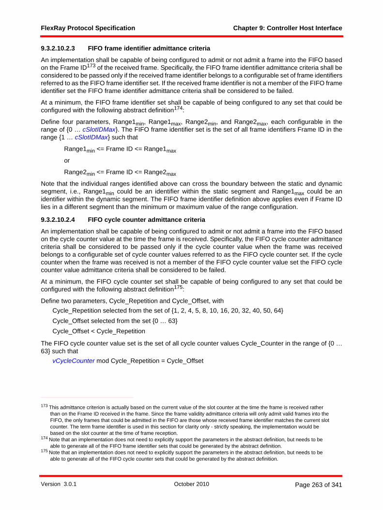
FlexRay Protocol Specification Chapter 9: Controller Host Interface
9.3.2.10.2.3 FIFO frame identifier admittance criteria
An implementation shall be capable of being configured to admit or not admit a frame into the FIFO basedon the Frame ID173 of the received frame. Specifically, the FIFO frame identifier admittance criteria shall beconsidered to be passed only if the received frame identifier belongs to a configurable set of frame identifiersreferred to as the FIFO frame identifier set. If the received frame identifier is not a member of the FIFO frameidentifier set the FIFO frame identifier admittance criteria shall be considered to be failed.
At a minimum, the FIFO frame identifier set shall be capable of being configured to any set that could beconfigured with the following abstract definition174:
Define four parameters, Range1min, Range1max, Range2min, and Range2max, each configurable in therange of {0 … cSlotIDMax}. The FIFO frame identifier set is the set of all frame identifiers Frame ID in therange {1 … cSlotIDMax} such that
Range1min <= Frame ID <= Range1max
or
Range2min <= Frame ID <= Range2max
Note that the individual ranges identified above can cross the boundary between the static and dynamicsegment, i.e., Range1min could be an identifier within the static segment and Range1max could be anidentifier within the dynamic segment. The FIFO frame identifier definition above applies even if Frame IDlies in a different segment than the minimum or maximum value of the range configuration.
9.3.2.10.2.4 FIFO cycle counter admittance criteria
An implementation shall be capable of being configured to admit or not admit a frame into the FIFO basedon the cycle counter value at the time the frame is received. Specifically, the FIFO cycle counter admittancecriteria shall be considered to be passed only if the cycle counter value when the frame was receivedbelongs to a configurable set of cycle counter values referred to as the FIFO cycle counter set. If the cyclecounter when the frame was received is not a member of the FIFO cycle counter value set the FIFO cyclecounter value admittance criteria shall be considered to be failed.
At a minimum, the FIFO cycle counter set shall be capable of being configured to any set that could beconfigured with the following abstract definition175:
Define two parameters, Cycle_Repetition and Cycle_Offset, withCycle_Repetition selected from the set of {1, 2, 4, 5, 8, 10, 16, 20, 32, 40, 50, 64} Cycle_Offset selected from the set {0 … 63} Cycle_Offset < Cycle_Repetition
The FIFO cycle counter value set is the set of all cycle counter values Cycle_Counter in the range of {0 …63} such that
vCycleCounter mod Cycle_Repetition = Cycle_Offset
173 This admittance criterion is actually based on the current value of the slot counter at the time the frame is received rather than on the Frame ID received in the frame. Since the frame validity admittance criteria will only admit valid frames into the FIFO, the only frames that could be admitted in the FIFO are those whose received frame identifier matches the current slot counter. The term frame identifier is used in this section for clarity only - strictly speaking, the implementation would be based on the slot counter at the time of frame reception.
174 Note that an implementation does not need to explicitly support the parameters in the abstract definition, but needs to be able to generate all of the FIFO frame identifier sets that could be generated by the abstract definition.
175 Note that an implementation does not need to explicitly support the parameters in the abstract definition, but needs to be able to generate all of the FIFO cycle counter sets that could be generated by the abstract definition.
Version 3.0.1 October 2010 Page 263 of 341

FlexRay Protocol Specification Chapter 9: Controller Host Interface
9.3.2.10.2.5 Message identifier admittance criteria
An implementation shall be capable of being configured to admit or not admit a frame into the FIFO basedon the value of the optional Message ID that can be present in frames received in the dynamic segment.Message identifier admittance criteria shall have the following characteristics:
The message identifier admittance criteria shall have three configurable parameters176:
1. MsgIDMask, an integer in the range of {0 … 65535}, which determines the bitwise AND mask value for the admittance criteria
2. MsgIDMatch, an integer in the range of {0 … 65535}, which determines the bitwise comparison value for the admittance criteria
3. AdmitWithoutMessageID, a Boolean configuration which determines whether or not frames received in the dynamic segment that don't contain a message ID will be admitted into the FIFO.
The message identifier admittance criteria shall have the following behavior:• If the frame was received in the static segment the frame is considered to have passed the message
identifier admittance criteria, or• If the frame was received in the dynamic segment and does not contain a message identifier (i.e.,
the payload preamble indicator of the frame is set to zero), the behavior depends on the AdmitWith-outMessageID configuration of the FIFO:
If AdmitWithoutMessageID = false the frame is considered to fail the message identifieradmittance criteria.
If AdmitWithoutMessageID = true the frame is considered to pass the message identifieradmittance criteria.
or• If the frame was received in the dynamic segment and does contain a message identifier (i.e., the
payload preamble indicator of the frame is set to one), the admittance depends on the value of themessage identifier, MessageID, and the FIFO configurations MsgIDMask and MsgIDMatch. Specif-ically, the frame is considered to pass the message identifier admittance criteria if
( MessageID & MsgIDMask ) = MsgIDMatch otherwise the frame is considered to fail the message identifier admittance criteria. Here the "&"symbol represents a bitwise AND of the binary representation of the values of MessageID andMsgIDMask177.
9.3.2.10.3 FIFO performance requirementsAn implementation shall provide at least one FIFO receive buffer structure.
A FIFO receive buffer structure shall have a depth of at least eight entries (i.e., in the absence of entriesbeing removed from the FIFO by the host, the FIFO shall be capable of storing at least eight frames fromthe protocol engine without any loss or overwrite of frame contents data or slot status data).
Each entry in a FIFO receive structure also has a "width", i.e., each entry in a FIFO shall be capable ofstoring a number of bytes of frame payload data greater than or equal to the implementation's capability tostore payload data for non-queued receive buffers. If a valid message is received whose payload is longerthan the configured width of a FIFO entry, or is longer than the implementation's maximum width for FIFO's,
176 Note that unlike other FIFO admittance criteria, an implementation must explicitly support the specified parameters of the message ID admittance criteria, i.e., it is not acceptable to support other means of configuring this admittance criteria.
177 For example, if MsgIDMask = 3855 (0x0F0F hex) and MsgIDMatch = 1537 (0x0601 hex), then a frame with a MessageID of 38641 (0x96F1 hex) would pass the admittance criteria, but a frame with MessageID 1538 (0x0602 hex) would fail the criteria. Note that a configuration with MsgIDMask = 0 and MsgIDMatch = 0 would pass this criteria for any frame regardless of message identifier.
Version 3.0.1 October 2010 Page 264 of 341
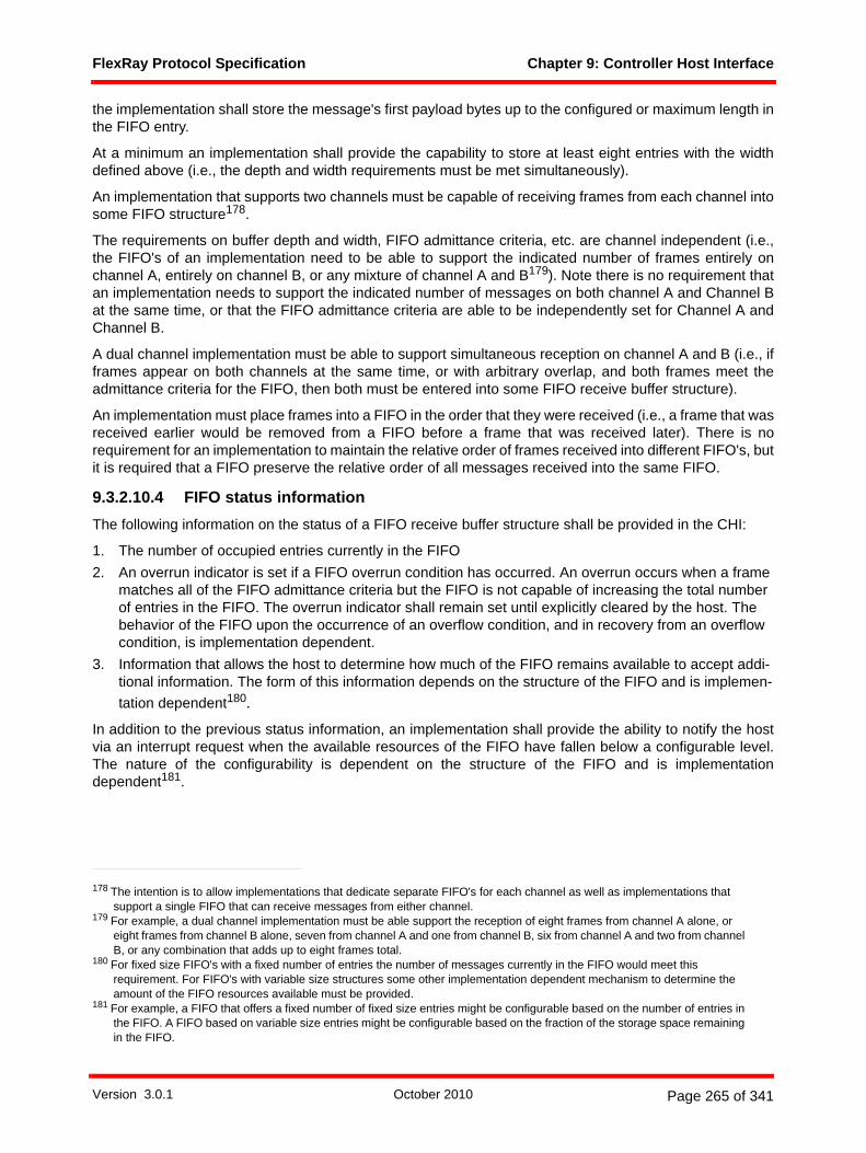
FlexRay Protocol Specification Chapter 9: Controller Host Interface
the implementation shall store the message's first payload bytes up to the configured or maximum length inthe FIFO entry.
At a minimum an implementation shall provide the capability to store at least eight entries with the widthdefined above (i.e., the depth and width requirements must be met simultaneously).
An implementation that supports two channels must be capable of receiving frames from each channel intosome FIFO structure178.
The requirements on buffer depth and width, FIFO admittance criteria, etc. are channel independent (i.e.,the FIFO's of an implementation need to be able to support the indicated number of frames entirely onchannel A, entirely on channel B, or any mixture of channel A and B179). Note there is no requirement thatan implementation needs to support the indicated number of messages on both channel A and Channel Bat the same time, or that the FIFO admittance criteria are able to be independently set for Channel A andChannel B.
A dual channel implementation must be able to support simultaneous reception on channel A and B (i.e., ifframes appear on both channels at the same time, or with arbitrary overlap, and both frames meet theadmittance criteria for the FIFO, then both must be entered into some FIFO receive buffer structure).
An implementation must place frames into a FIFO in the order that they were received (i.e., a frame that wasreceived earlier would be removed from a FIFO before a frame that was received later). There is norequirement for an implementation to maintain the relative order of frames received into different FIFO's, butit is required that a FIFO preserve the relative order of all messages received into the same FIFO.
9.3.2.10.4 FIFO status informationThe following information on the status of a FIFO receive buffer structure shall be provided in the CHI:
1. The number of occupied entries currently in the FIFO 2. An overrun indicator is set if a FIFO overrun condition has occurred. An overrun occurs when a frame
matches all of the FIFO admittance criteria but the FIFO is not capable of increasing the total number of entries in the FIFO. The overrun indicator shall remain set until explicitly cleared by the host. The behavior of the FIFO upon the occurrence of an overflow condition, and in recovery from an overflow condition, is implementation dependent.
3. Information that allows the host to determine how much of the FIFO remains available to accept addi-tional information. The form of this information depends on the structure of the FIFO and is implemen-tation dependent180.
In addition to the previous status information, an implementation shall provide the ability to notify the hostvia an interrupt request when the available resources of the FIFO have fallen below a configurable level.The nature of the configurability is dependent on the structure of the FIFO and is implementationdependent181.
178 The intention is to allow implementations that dedicate separate FIFO's for each channel as well as implementations that support a single FIFO that can receive messages from either channel.
179 For example, a dual channel implementation must be able support the reception of eight frames from channel A alone, or eight frames from channel B alone, seven from channel A and one from channel B, six from channel A and two from channel B, or any combination that adds up to eight frames total.
180 For fixed size FIFO's with a fixed number of entries the number of messages currently in the FIFO would meet this requirement. For FIFO's with variable size structures some other implementation dependent mechanism to determine the amount of the FIFO resources available must be provided.
181 For example, a FIFO that offers a fixed number of fixed size entries might be configurable based on the number of entries in the FIFO. A FIFO based on variable size entries might be configurable based on the fraction of the storage space remaining in the FIFO.
Version 3.0.1 October 2010 Page 265 of 341

FlexRay Protocol Specification Chapter 9: Controller Host Interface
9.3.3 CHI Services
9.3.3.1 Macrotick timer serviceThe CHI shall provide at least two absolute timers capable of notifying the host at expiration.
Each of the required timers shall, at a minimum, be capable of being configured with the following expirationcriteria:
• To expire at an absolute time in terms of cycle count and macrotick, i.e. the timer would expire at aconfigurable macrotick in a configurable communication cycle, and
• To expire at a configurable macrotick only (i.e., the timer would expire at a configurable macrotickindependent of cycle count)
In addition, each of the required timers shall, at a minimum, be capable of supporting the following twomodes of operation:
• A non-repetitive mode of operation where the timer will expire once the configured expiration criteriaoccurs and will not expire again until restarted or reconfigured by the host, and
• A repetitive mode of operation where the timer will expire every time the configured expirationcriteria occurs (i.e., the timer can expire multiple times without further interaction from the host).
It shall be possible to configure and activate a timer when the protocol is in either the POC:normal activestate or the POC:normal passive state.182
All absolute timers shall be deactivated when the protocol leaves the POC:normal active state or thePOC:normal passive state apart from transitions between the POC:normal active state and the POC:normalpassive state. It shall also be possible for the host to deactivate an absolute timer in any state that allowsthe timer to be activated. Once deactivated, a timer must be explicitly activated again by the host before itcan expire again.
9.3.3.2 Interrupt serviceThe interrupt service provides a set of configurable interrupt requests to the host based on a set of interruptsources reflecting events that occur in the protocol engine or the CHI.
At a minimum, an implementation shall provide the following interrupt sources:• Each timer (as described in section 9.3.3.1) provided by an implementation shall be able to act as
an interrupt source with the event being the expiration of the timer.• The FlexRay cycle shall act as an interrupt source with the event being the start of a FlexRay cycle.
This requirement is in addition to the previous timer requirement (i.e., it is not acceptable to meetthis requirement through the use of a timer as specified in section 9.3.3.1).
• State transitions of the Protocol Operation Control process shall act as an interrupt source. Thissource shall only signal an event whenever the POC transitions to the POC:halt, POC:ready,POC:normal active or POC:normal passive states for any reason other than the processing of anIMMEDIATE_READY or FREEZE command.
• Each FIFO structure shall act as an interrupt source with the event being a frame reception thatcauses the available resources of the FIFO structure fall below a configurable level (refer to section9.3.2.10.4).
An implementation shall provide a mechanism that allows the events of interrupt sources to generateinterrupt requests (i.e., maps interrupt source events to interrupt requests). In general, a single interruptrequest is allowed to support more than one interrupt source, however at least one of the mandated
182 It is allowed, but not required, for an implementation to support configuration/activation of an absolute timer in states other than POC:normal active and POC:normal passive.
Version 3.0.1 October 2010 Page 266 of 341

FlexRay Protocol Specification Chapter 9: Controller Host Interface
absolute timers (see section 9.3.3.1) shall provide a dedicated interrupt request that is not shared with anyother interrupt source.
It shall be possible for the host to enable and disable the generation of interrupt requests for interruptsources. When interrupt request generation is enabled for an interrupt source the event defined for theinterrupt source shall cause the generation of a corresponding interrupt request. When interrupt requestgeneration is disabled for an interrupt source the event defined for the interrupt source shall not cause thegeneration of a corresponding interrupt request.
An implementation shall provide control of interrupt request generation with at least two levels. At the firstlevel, it shall be possible for the host to individually control whether interrupt request generation is enabledor disabled for each interrupt source. At the second level, it shall be possible for the host to globally disableall interrupt request generation regardless of the individual interrupt request generation enabled / disabledstatus of each interrupt source. Specifically, if interrupt request generation is globally disabled no interruptsource will generate interrupt requests; if interrupt request generation is not globally disabled each interruptsource shall generate interrupt requests according to its individual interrupt request generation status.
An implementation shall provide an interrupt status indication for each interrupt source. The interrupt statusindication for an interrupt source shall be set when the interrupt source's event occurs183 and shall remainset until reset under control of the host.
9.3.3.3 Message ID filtering serviceThe message ID filtering service provides means for selecting receive buffers based on a message ID thatmay be exchanged in the first two bytes of the payload segment of selected frames within the dynamicsegment that have the payload preamble indicator set to one in the header of the frame.
To support this service the message buffer configuration data shall allow the host to configure the payloadpreamble indicator for each transmit buffer so that the host can configure whether the message datacontains a message ID or not (refer to section 9.3.2.5.1).
Message ID filtering is required for at least one FIFO receive buffer structure as described in sections9.3.2.10.2.5 and 9.3.2.10.3.
9.3.3.4 Network management serviceThe network management service provides means for exchanging and processing network managementdata. This service supports high-level host-based network management protocols that provide cluster-widecoordination of shutdown decisions based on the actual application state. The network management servicemay also be used by applications to implement other functionality.
Network management is performed by exchanging a network management vector in selected networkmanagement enabled frames within the static segment of the communication cycle that have the payloadpreamble indicator set to one in the header of the frame. The payload preamble indicator of the messagebuffer configuration data allows the host to configure whether or not a message contains a networkmanagement vector.
Throughout each communication cycle the CHI shall maintain an accrued network management vector byapplying a bit-wise OR between the current accrued network management vector and each184 networkmanagement vector received in a valid frame on each channel (regardless of whether or not any receivebuffer is configured to explicitly receive the valid frame).185
183 The interrupt status indication of an interrupt source is set whenever the corresponding event occurs irrespective of whether interrupt request generation is individually enabled for the interrupt source or whether interrupt request generation is globally disabled.
184 Only valid frames reported to the CHI (via the vRF structures of the channel-specific FSP processes) are considered. If more than one frame occurs in a slot on a given channel only the first valid frame (i.e., the one reported in vRF) is considered.
Version 3.0.1 October 2010 Page 267 of 341

FlexRay Protocol Specification Chapter 9: Controller Host Interface
1. If pNMVectorEarlyUpdate is set to false, the protocol status data shall contain a snapshot of the accrued network management vector that shall be updated no sooner than the end of the cycle and no later than the availability of the NIT status information or the availability of the payload data from the last static slot, whichever occurs later. The snapshot shall contain the value of the accrued network management vector at the end of the cycle, and shall include the effects of any reception that may have occurred in the last static slot.
2. If pNMVectorEarlyUpdate is set to true, the protocol status data shall contain a snapshot of the accrued network management vector that shall be updated no sooner than the end of the static seg-ment and no later than the availability of the payload data from the last static slot. The snapshot shall contain the value of the accrued network management vector at the end of the static segment (i.e., shall include the effects of any reception that may have occurred in the last static slot).
3. These updates take place as long as the protocol is in either the POC:normal active state or the POC:normal passive state.
4. The accrued network management vector is set to zero at the beginning of each communication cycle.186
5. Following the completion of startup, the NM vector snapshot shall be set to all zeros prior to the first update of the NM vector snapshot (when this occurs depends on the configuration parameter pNM-VectorEarlyUpdate).
In addition to the capabilities provided above, it is also possible for implementers to provide additional typesof Network Management Services, for example, providing direct (non-OR'd) access to the NM Vector data.
185 In this context, a frame is only considered valid if vSS!ValidFrame status is set to true when the protocol engine exports the slot status vSS to the CHI at the end of a slot or segment. For example, frames that are received in a slot which is also used for transmission shall not be accrued into the network management vector since such frames will have vSS!ValidFrame set to false when the slot status is exported to the CHI.
186 Even though the snapshot of the NM vector described in item 1 might be presented to the CHI after the end of the cycle, it must represent the status of the accrued NM vector from the previous cycle. As a result, the snapshot must be taken before the vector is set to zero at the beginning of the subsequent cycle.
Version 3.0.1 October 2010 Page 268 of 341

FlexRay Protocol Specification Appendix A: System Parameters
Appendix ASystem Parameters
A.1 Protocol constants
Name Description Value
cChannelIdleDelimiter Duration of the channel idle delimiter. 11 gdBit
cClockDeviationMax Maximum clock frequency deviation, equivalent to 1500 ppm (1500ppm = 1500/1000000 = 0.0015).
0.0015
cCrcInit[A] Initialization vector for the calculation of the frame CRC on channel A (hexadecimal).
0xFEDCBA
cCrcInit[B] Initialization vector for the calculation of the frame CRC on channel B (hexadecimal).
0xABCDEF
cCrcPolynomial Frame CRC polynomial (hexadecimal). 0x5D6DCB
cCrcSize Size of the frame CRC calculation register. 24 bits
cCycleCountMax Maximum cycle counter value in any cluster. 63
cdBSS Duration of the Byte Start Sequence. 2 gdBit
cdCAS Duration of the logical low portion of the collision avoid-ance symbol (CAS) and media access test symbol (MTS).
30 gdBit
cdCASActionPointOffset Initialization value of the CAS action point offset timer. 1 MT
cdCASRxLowMin Lower limit of the CAS acceptance window. 29 gdBit
cdCycleMax Maximum cycle length. 16000 µs
cdCycleStartTimeout Maximum allowed jitter between the 'external cycle start' from the time gateway source and the internal 'cycle start' of the time gateway sink.
5 µT
cdFES Duration of the Frame End Sequence. 2 gdBit
cdFSS Duration of the Frame Start Sequence. 1 gdBit
cdInternalRxDelayMax Maximum value of the implementation specific delay on the receive path of the decoder.
4 samplesa
cdInternalRxDelayMin Minimum value of the implementation specific delay on the receive path of the decoder.
1 samplea
cdMaxMTNomb Maximum duration of a nominal macrotick. An implemen-tation must be able to support nominal macrotick dura-tions between cdMinMTNom and cdMaxMTNom.
6 µs
Table A-1: Protocol constants.
Version 3.0.1 October 2010 Page 269 of 341
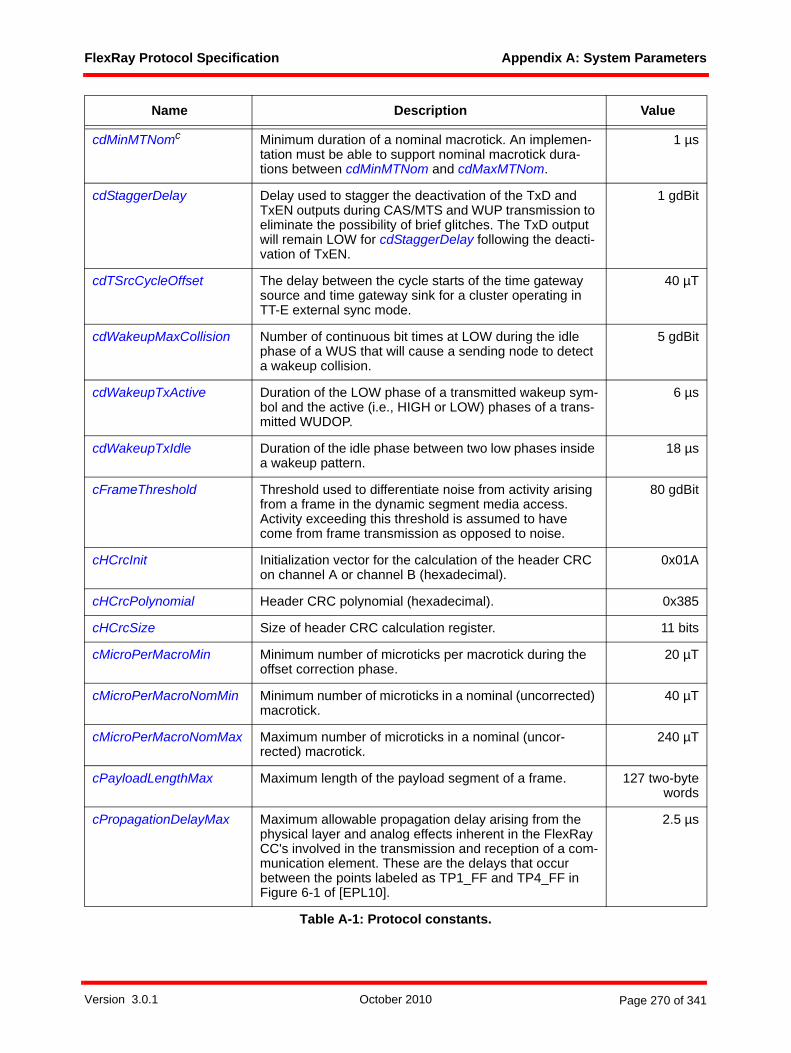
FlexRay Protocol Specification Appendix A: System Parameters
cdMinMTNomc Minimum duration of a nominal macrotick. An implemen-tation must be able to support nominal macrotick dura-tions between cdMinMTNom and cdMaxMTNom.
1 µs
cdStaggerDelay Delay used to stagger the deactivation of the TxD and TxEN outputs during CAS/MTS and WUP transmission to eliminate the possibility of brief glitches. The TxD output will remain LOW for cdStaggerDelay following the deacti-vation of TxEN.
1 gdBit
cdTSrcCycleOffset The delay between the cycle starts of the time gateway source and time gateway sink for a cluster operating in TT-E external sync mode.
40 µT
cdWakeupMaxCollision Number of continuous bit times at LOW during the idle phase of a WUS that will cause a sending node to detect a wakeup collision.
5 gdBit
cdWakeupTxActive Duration of the LOW phase of a transmitted wakeup sym-bol and the active (i.e., HIGH or LOW) phases of a trans-mitted WUDOP.
6 µs
cdWakeupTxIdle Duration of the idle phase between two low phases inside a wakeup pattern.
18 µs
cFrameThreshold Threshold used to differentiate noise from activity arising from a frame in the dynamic segment media access. Activity exceeding this threshold is assumed to have come from frame transmission as opposed to noise.
80 gdBit
cHCrcInit Initialization vector for the calculation of the header CRC on channel A or channel B (hexadecimal).
0x01A
cHCrcPolynomial Header CRC polynomial (hexadecimal). 0x385
cHCrcSize Size of header CRC calculation register. 11 bits
cMicroPerMacroMin Minimum number of microticks per macrotick during the offset correction phase.
20 µT
cMicroPerMacroNomMin Minimum number of microticks in a nominal (uncorrected) macrotick.
40 µT
cMicroPerMacroNomMax Maximum number of microticks in a nominal (uncor-rected) macrotick.
240 µT
cPayloadLengthMax Maximum length of the payload segment of a frame. 127 two-bytewords
cPropagationDelayMax Maximum allowable propagation delay arising from the physical layer and analog effects inherent in the FlexRay CC's involved in the transmission and reception of a com-munication element. These are the delays that occur between the points labeled as TP1_FF and TP4_FF in Figure 6-1 of [EPL10].
2.5 µs
Name Description Value
Table A-1: Protocol constants.
Version 3.0.1 October 2010 Page 270 of 341
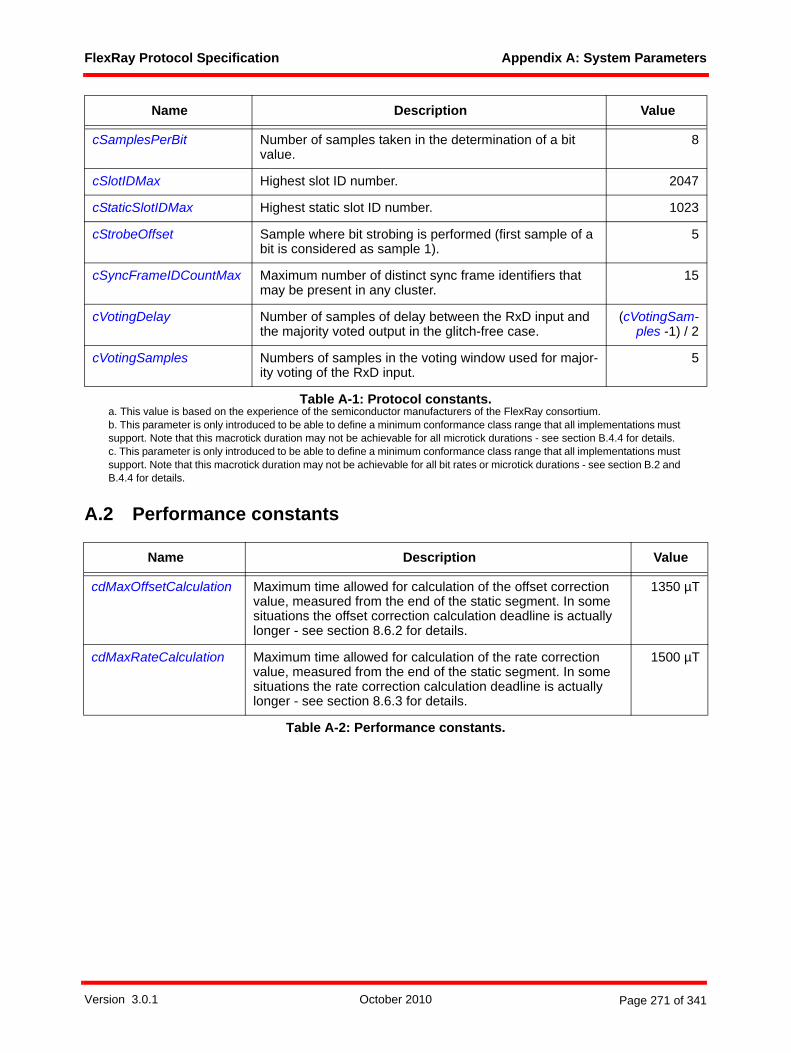
FlexRay Protocol Specification Appendix A: System Parameters
A.2 Performance constants
cSamplesPerBit Number of samples taken in the determination of a bit value.
8
cSlotIDMax Highest slot ID number. 2047
cStaticSlotIDMax Highest static slot ID number. 1023
cStrobeOffset Sample where bit strobing is performed (first sample of a bit is considered as sample 1).
5
cSyncFrameIDCountMax Maximum number of distinct sync frame identifiers that may be present in any cluster.
15
cVotingDelay Number of samples of delay between the RxD input and the majority voted output in the glitch-free case.
(cVotingSam-ples -1) / 2
cVotingSamples Numbers of samples in the voting window used for major-ity voting of the RxD input.
5
a. This value is based on the experience of the semiconductor manufacturers of the FlexRay consortium.b. This parameter is only introduced to be able to define a minimum conformance class range that all implementations must support. Note that this macrotick duration may not be achievable for all microtick durations - see section B.4.4 for details.c. This parameter is only introduced to be able to define a minimum conformance class range that all implementations must support. Note that this macrotick duration may not be achievable for all bit rates or microtick durations - see section B.2 and B.4.4 for details.
Name Description Value
cdMaxOffsetCalculation Maximum time allowed for calculation of the offset correction value, measured from the end of the static segment. In some situations the offset correction calculation deadline is actually longer - see section 8.6.2 for details.
1350 µT
cdMaxRateCalculation Maximum time allowed for calculation of the rate correction value, measured from the end of the static segment. In some situations the rate correction calculation deadline is actually longer - see section 8.6.3 for details.
1500 µT
Table A-2: Performance constants.
Name Description Value
Table A-1: Protocol constants.
Version 3.0.1 October 2010 Page 271 of 341

FlexRay Protocol Specification Appendix B: Configuration Constraints
Appendix BConfiguration Constraints
B.1 GeneralThis appendix specifies the configurable parameters of the FlexRay protocol. This appendix also identifiesthe configurable range of the parameters, and gives constraints on the values that the parameters may takeon. All implementations that support a given parameter must support at least the parameter range identifiedin this appendix. An implementation is allowed, however, to support a broader range of configuration values.
Following functions are used for the configuration parameter calculation:
1. Function ceil(x) returns the nearest integer greater than or equal to x.2. Function floor(x) returns the nearest integer less than or equal to x. 3. Function max(x1; x2;…; xn) returns the maximum value from the set of arguments {x1, x2,…, xn }. If
the arguments xi are compound expressions composed of multiple parameters, then the values selected for each of the parameters should be the ones that maximize the overall value of xi.
4. Function min(x1; x2;…; xn) returns the minimum value from the set of arguments {x1, x2,…, xn }. If the arguments xi are compound expressions composed of multiple parameters, then the values selected for each of the parameters should be the ones that minimize the overall value of xi.
5. Function round(x) returns the integer value closest to x using asymmetric arithmetic rounding.6. Function if(c; x; y) returns x if condition c is true, otherwise y.7. [ ] denotes units.8. maxM,N(...) means the maximum of all paths from node M to node N with M,N = 1, .., number of nodes
and M <> N.9. Function or(c1; c2) returns true if either condition c1 or condition c2 (or both) are true, otherwise
returns false.10. Function minN(xN) returns the value x of node N that represents the minimum of all nodes of a cluster.
11. Function maxN(xN) returns the value x of node N that represents the maximum of all nodes of a clus-ter.
B.2 Bit ratesThe FlexRay protocol specification defines three standard bit rates - 10 Mbit/s, 5 Mbit/s, and 2.5 Mbit/s. Theconfiguration ranges shown in this appendix reflect the necessary parameter ranges for an implementationthat supports operation at all three standard speeds.
Version 3.0.1 October 2010 Page 272 of 341

FlexRay Protocol Specification Appendix B: Configuration Constraints
B.3 ParametersB.3.1 Global cluster parameters
B.3.1.1 Protocol relevant Protocol relevant global cluster parameters are parameters used within the SDL models to describe theFlexRay protocol. They must have the same value in all nodes of a cluster.
Name Description Range
gColdstartAttempts Maximum number of times a node in the cluster is per-mitted to attempt to start the cluster by initiating sched-ule synchronization.
2 - 31
gCycleCountMax Maximum cycle counter value in a given cluster. [7, 9 , ..., cCycle-CountMax]a
gdActionPointOffset Number of macroticks the action point is offset from the beginning of a static slot.
1 - 63 MT
gdCASRxLowMax Upper limit of the CAS acceptance window. 28 - 254 gdBit
gdDynamicSlotIdlePhase Duration of the idle phase within a dynamic slot. 0 - 2 Minislot
gdIgnoreAfterTx Duration that bit strobing is paused after a transmission. 0 - 15 gdBit
gdMinislot Duration of a minislot. 2 - 63 MT
gdMinislotActionPoint-Offset
Number of macroticks the minislot action point is offset from the beginning of a minislot.
1 - 31 MT
gdStaticSlot Duration of a static slot. 3 - 664 MT
gdSymbolWindow Duration of the symbol window. 0 - 162 MT
gdSymbolWindowAction-PointOffset
Number of macroticks the action point is offset from the beginning of the symbol window.
1 - 63 MT
gdTSSTransmitter Number of bits in the Transmission Start Sequence. 1 - 15 gdBit
gdWakeupRxIdle Number of bits used by the node to test the duration ofthe 'idle' or HIGH phase of a received wakeup.
8 - 59 gdBit
gdWakeupRxLow Number of bits used by the node to test the duration ofthe LOW phase of a received wakeup.
8 - 59 gdBit
gdWakeupRxWindow The size of the window, expressed in bits, used to detectwakeups.
76 - 485 gdBit
gdWakeupTxActive Number of bits used by the node to transmit the LOW phase of a wakeup symbol and the HIGH and LOW phases of a WUDOP.
15 - 60 gdBit
gdWakeupTxIdle Number of bits used by the node to transmit the 'idle' part of a wakeup symbol.
45 - 180 gdBit
Table B-1: Global protocol relevant parameters.
Version 3.0.1 October 2010 Page 273 of 341

FlexRay Protocol Specification Appendix B: Configuration Constraints
B.3.1.2 Protocol relatedProtocol related global cluster parameters are parameters that have a meaning in the context of the FlexRayprotocol but are not used within the SDL models. These parameters are used in the configurationconstraints. They must have the same value in all nodes of a cluster.
gListenNoise Upper limit for the startup listen timeout and wakeup lis-ten timeout in the presence of noise. This is used as a multiplier of the node parameter pdListenTimeout.
2 - 16
gMacroPerCycle Number of macroticks in a communication cycle. 8 - 16000 MT
gMaxWithoutClockCor-rectionFatal
Threshold used for testing the vClockCorrectionFailed counter. Defines the number of consecutive even/odd cycle pairs with missing clock correction terms that will cause the protocol to transition from the POC:normal active or POC:normal passive state into the POC:halt state.b
1 - 15 even/oddcycle pairs
gMaxWithoutClockCor-rectionPassive
Threshold used for testing the vClockCorrectionFailed counter. Defines the number of consecutive even/odd cycle pairs with missing clock correction terms that will cause the protocol to transition from the POC:normal active state to the POC:normal passive state.b
1 - 15 even/oddcycle pairs
gNumberOfMinislots Number of minislots in the dynamic segment. 0 - 7988
gNumberOfStaticSlots Number of static slots in the static segment. 2 - cStatic-SlotIDMax
gPayloadLengthStatic Payload length of a static frame.c 0 - cPayload-LengthMax two-
byte words
gSyncFrameIDCount-Max
Maximum number of distinct sync frame identifiers present in a given cluster.
2 - cSyncFrame-IDCountMax
a. must be an odd integerb. If gMaxWithoutClockCorrectionPassive is set to a value greater than or equal to gMaxWithoutClockCorrectionFatal then the CC enters the POC:halt state directly (i.e., without first entering the POC:normal passive state).c. All static frames in a cluster have the same payload length. For 2.5 Mbit/s the payload length is restricted by the maxi-mum transmission duration of adTxMax. See section B.4.40.
Name Description Range
gChannels The channels that are used by the cluster. [A, B, A&B]
gClockDeviationMax Maximum frequency deviation of the time sources inside a cluster from their nominal frequencies.
0 < gClockDevia-tionMax <= cClock-
DeviationMax
Table B-2: Global protocol related parameters.
Name Description Range
Table B-1: Global protocol relevant parameters.
Version 3.0.1 October 2010 Page 274 of 341

FlexRay Protocol Specification Appendix B: Configuration Constraints
B.3.2 Node parameters
B.3.2.1 Protocol relevantProtocol relevant node parameters are parameters used within the SDL models to describe the FlexRayprotocol. They may have different values in different nodes of a cluster.
gClusterDriftDamping The cluster drift damping factor, based on the longest microtick adMicrotickMax used in the cluster. Used to compute the local cluster drift damping factor pCluster-DriftDamping.
0 - 5 µT
gdBit Nominal bit time. [0.1, 0.2, 0.4] µs
gdCycle Length of the cycle. 24 µsa -cdCycleMax
gdMacrotick Duration of the cluster wide nominal macrotick. 1 - 6 µs
gdNIT Duration of the Network Idle Time. 2 - 15978 MT
gdSampleClockPeriod Sample clock period. [0.0125, 0.025,0.05] µs
gExternOffsetCorrec-tion
External offset correction value applied in a cluster. 0 - 0.35 µs
gExternRateCorrection External rate correction value applied in a cluster. 0 - 0.35 µs
gNetworkManage-mentVectorLength
Length of the Network Management vector in a cluster. 0 - 12 bytes
a. See the calculation for the minimum value of pMicroPerCycle in section B.4.15. Maximum value is given by cdCycle-Max. The minimum value is a theoretical minimum. Implementations may require larger minimum cycle length because of other conditions (for example performance constants given in table A-2).
Name Description Range
pAllowHaltDueToClock Boolean parameter that controls the transition to the POC:halt state due to clock synchronization errors. If set to true, the CC is allowed to transition to POC:halt.If set to false, the CC will not transition to the POC:halt state but will enter or remain in the POC:normal pas-sive state (self healing would still be possible).
Boolean
pAllowPassiveToActive Number of consecutive even/odd cycle pairs that must have valid clock correction terms before the CC will be allowed to transition from the POC:normal passive state to POC:normal active state. If set to zero, the CC is not allowed to transition from POC:normal passive to POC:normal active.
0 - 31 even/oddcycle pairs
pChannels Channels to which the node is connected. [A, B, A&B]
Table B-3: Local node protocol relevant parameters.
Name Description Range
Table B-2: Global protocol related parameters.
Version 3.0.1 October 2010 Page 275 of 341

FlexRay Protocol Specification Appendix B: Configuration Constraints
pClusterDriftDamping Local cluster drift damping factor used for rate correc-tion.
0 - 10 µT
pdAcceptedStartup-Range
Expanded range of measured clock deviation allowed for startup frames during integration.
29 - 2743 µT
pDecodingCorrection Value used by the receiver to calculate the differencebetween primary time reference point and secondarytime reference point.
12 - 136 µT
pDelayCompensa-tion[A], pDelayCompen-sation[B]
Value used to compensate for reception delays on theindicated channel.
4 - 211 µT
pdListenTimeout Value for the startup listen timeout and wakeup listen timeout. Although this is a node local parameter, the real time equivalent of this value should be the same for all nodes in the cluster.
1926 - 2567692µT
pExternalSync Parameter indicating whether the node is externally synchronized (operating as time gateway sink in an TT-E cluster) or locally synchronized. If pExternalSync is set to true then pTwoKeySlotMode must also be set to true.
Boolean
pExternOffsetCorrection Number of microticks added or subtracted to the NIT to carry out a host-controlled external offset correction.
0 - 28 µT
pExternRateCorrection Number of microticks added or subtracted to the cycle to carry out a host-controlled external rate correction.
0 - 28 µT
pFallBackInternal Parameter indicating whether a time gateway sink node will switch to local clock operation when synchroniza-tion with the time gateway source node is lost (pFall-BackInternal = true) or will instead go to POC:halt (pFallBackInternal = false).
Boolean
pKeySlotID ID of the key slot, i.e., the slot used to transmit the startup frame, sync frame, or designated key slot frame. If this parameter is set to zero the node does not have a key slot.
0 - cStaticSlot-IDMax
pKeySlotOnlyEnabled Parameter indicating whether or not the node shall enter key slot only mode following startup.
Boolean
pKeySlotUsedForStartup Parameter indicating whether the key slot(s) are used to transmit startup frames. If pKeySlotUsedForStartup is set to true then pKeySlotUsedForSync must also be set to true. If pTwoKeySlotMode is set to true then both pKeySlotUsedForSync and pKeySlotUsedForStartup must also be set to true.
Boolean
Name Description Range
Table B-3: Local node protocol relevant parameters.
Version 3.0.1 October 2010 Page 276 of 341
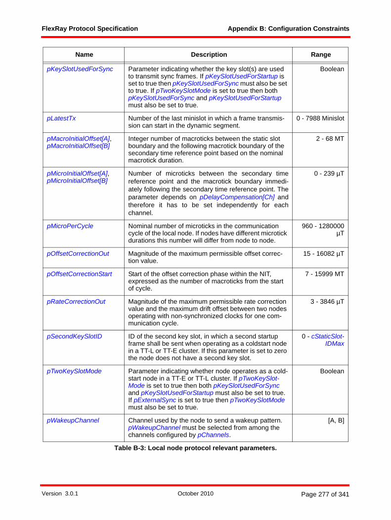
FlexRay Protocol Specification Appendix B: Configuration Constraints
pKeySlotUsedForSync Parameter indicating whether the key slot(s) are used to transmit sync frames. If pKeySlotUsedForStartup is set to true then pKeySlotUsedForSync must also be set to true. If pTwoKeySlotMode is set to true then both pKeySlotUsedForSync and pKeySlotUsedForStartup must also be set to true.
Boolean
pLatestTx Number of the last minislot in which a frame transmis-sion can start in the dynamic segment.
0 - 7988 Minislot
pMacroInitialOffset[A],pMacroInitialOffset[B]
Integer number of macroticks between the static slot boundary and the following macrotick boundary of the secondary time reference point based on the nominal macrotick duration.
2 - 68 MT
pMicroInitialOffset[A], pMicroInitialOffset[B]
Number of microticks between the secondary timereference point and the macrotick boundary immedi-ately following the secondary time reference point. Theparameter depends on pDelayCompensation[Ch] andtherefore it has to be set independently for eachchannel.
0 - 239 µT
pMicroPerCycle Nominal number of microticks in the communication cycle of the local node. If nodes have different microtick durations this number will differ from node to node.
960 - 1280000µT
pOffsetCorrectionOut Magnitude of the maximum permissible offset correc-tion value.
15 - 16082 µT
pOffsetCorrectionStart Start of the offset correction phase within the NIT, expressed as the number of macroticks from the start of cycle.
7 - 15999 MT
pRateCorrectionOut Magnitude of the maximum permissible rate correction value and the maximum drift offset between two nodes operating with non-synchronized clocks for one com-munication cycle.
3 - 3846 µT
pSecondKeySlotID ID of the second key slot, in which a second startup frame shall be sent when operating as a coldstart node in a TT-L or TT-E cluster. If this parameter is set to zero the node does not have a second key slot.
0 - cStaticSlot-IDMax
pTwoKeySlotMode Parameter indicating whether node operates as a cold-start node in a TT-E or TT-L cluster. If pTwoKeySlot-Mode is set to true then both pKeySlotUsedForSync and pKeySlotUsedForStartup must also be set to true. If pExternalSync is set to true then pTwoKeySlotMode must also be set to true.
Boolean
pWakeupChannel Channel used by the node to send a wakeup pattern. pWakeupChannel must be selected from among the channels configured by pChannels.
[A, B]
Name Description Range
Table B-3: Local node protocol relevant parameters.
Version 3.0.1 October 2010 Page 277 of 341
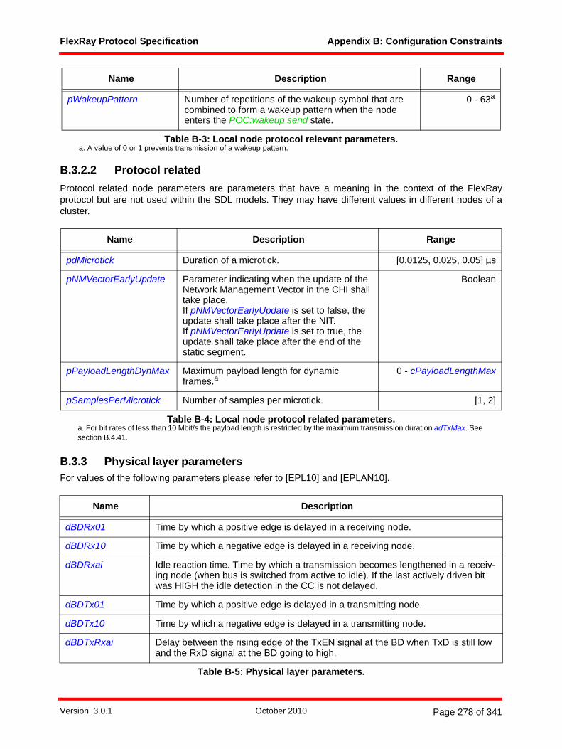
FlexRay Protocol Specification Appendix B: Configuration Constraints
B.3.2.2 Protocol relatedProtocol related node parameters are parameters that have a meaning in the context of the FlexRayprotocol but are not used within the SDL models. They may have different values in different nodes of acluster.
B.3.3 Physical layer parametersFor values of the following parameters please refer to [EPL10] and [EPLAN10].
pWakeupPattern Number of repetitions of the wakeup symbol that are combined to form a wakeup pattern when the node enters the POC:wakeup send state.
0 - 63a
a. A value of 0 or 1 prevents transmission of a wakeup pattern.
Name Description Range
pdMicrotick Duration of a microtick. [0.0125, 0.025, 0.05] µs
pNMVectorEarlyUpdate Parameter indicating when the update of the Network Management Vector in the CHI shall take place.If pNMVectorEarlyUpdate is set to false, the update shall take place after the NIT.If pNMVectorEarlyUpdate is set to true, the update shall take place after the end of the static segment.
Boolean
pPayloadLengthDynMax Maximum payload length for dynamic frames.a
a. For bit rates of less than 10 Mbit/s the payload length is restricted by the maximum transmission duration adTxMax. See section B.4.41.
0 - cPayloadLengthMax
pSamplesPerMicrotick Number of samples per microtick. [1, 2]
Table B-4: Local node protocol related parameters.
Name Description
dBDRx01 Time by which a positive edge is delayed in a receiving node.
dBDRx10 Time by which a negative edge is delayed in a receiving node.
dBDRxai Idle reaction time. Time by which a transmission becomes lengthened in a receiv-ing node (when bus is switched from active to idle). If the last actively driven bit was HIGH the idle detection in the CC is not delayed.
dBDTx01 Time by which a positive edge is delayed in a transmitting node.
dBDTx10 Time by which a negative edge is delayed in a transmitting node.
dBDTxRxai Delay between the rising edge of the TxEN signal at the BD when TxD is still low and the RxD signal at the BD going to high.
Table B-5: Physical layer parameters.
Name Description Range
Table B-3: Local node protocol relevant parameters.
Version 3.0.1 October 2010 Page 278 of 341
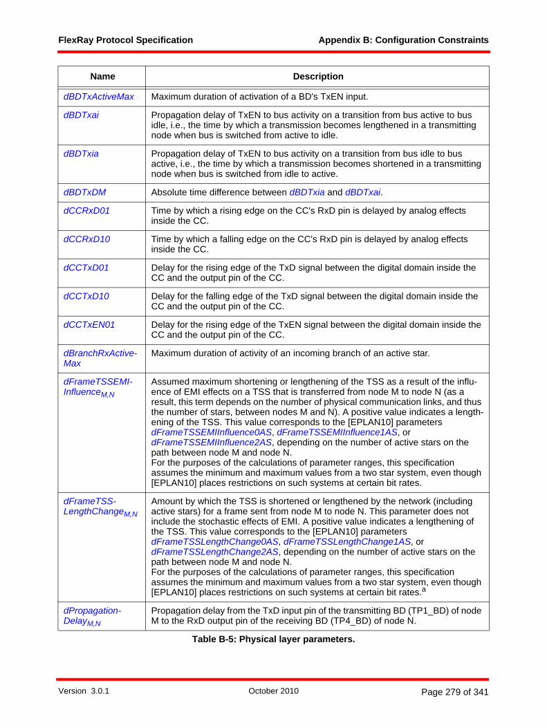
FlexRay Protocol Specification Appendix B: Configuration Constraints
dBDTxActiveMax Maximum duration of activation of a BD's TxEN input.
dBDTxai Propagation delay of TxEN to bus activity on a transition from bus active to bus idle, i.e., the time by which a transmission becomes lengthened in a transmitting node when bus is switched from active to idle.
dBDTxia Propagation delay of TxEN to bus activity on a transition from bus idle to bus active, i.e., the time by which a transmission becomes shortened in a transmitting node when bus is switched from idle to active.
dBDTxDM Absolute time difference between dBDTxia and dBDTxai.
dCCRxD01 Time by which a rising edge on the CC's RxD pin is delayed by analog effects inside the CC.
dCCRxD10 Time by which a falling edge on the CC's RxD pin is delayed by analog effects inside the CC.
dCCTxD01 Delay for the rising edge of the TxD signal between the digital domain inside the CC and the output pin of the CC.
dCCTxD10 Delay for the falling edge of the TxD signal between the digital domain inside the CC and the output pin of the CC.
dCCTxEN01 Delay for the rising edge of the TxEN signal between the digital domain inside the CC and the output pin of the CC.
dBranchRxActive-Max
Maximum duration of activity of an incoming branch of an active star.
dFrameTSSEMI-InfluenceM,N
Assumed maximum shortening or lengthening of the TSS as a result of the influ-ence of EMI effects on a TSS that is transferred from node M to node N (as a result, this term depends on the number of physical communication links, and thus the number of stars, between nodes M and N). A positive value indicates a length-ening of the TSS. This value corresponds to the [EPLAN10] parameters dFrameTSSEMIInfluence0AS, dFrameTSSEMIInfluence1AS, or dFrameTSSEMIInfluence2AS, depending on the number of active stars on the path between node M and node N.For the purposes of the calculations of parameter ranges, this specification assumes the minimum and maximum values from a two star system, even though [EPLAN10] places restrictions on such systems at certain bit rates.
dFrameTSS-LengthChangeM,N
Amount by which the TSS is shortened or lengthened by the network (including active stars) for a frame sent from node M to node N. This parameter does not include the stochastic effects of EMI. A positive value indicates a lengthening of the TSS. This value corresponds to the [EPLAN10] parameters dFrameTSSLengthChange0AS, dFrameTSSLengthChange1AS, or dFrameTSSLengthChange2AS, depending on the number of active stars on the path between node M and node N.For the purposes of the calculations of parameter ranges, this specification assumes the minimum and maximum values from a two star system, even though [EPLAN10] places restrictions on such systems at certain bit rates.a
dPropagation-DelayM,N
Propagation delay from the TxD input pin of the transmitting BD (TP1_BD) of node M to the RxD output pin of the receiving BD (TP4_BD) of node N.
Name Description
Table B-5: Physical layer parameters.
Version 3.0.1 October 2010 Page 279 of 341

FlexRay Protocol Specification Appendix B: Configuration Constraints
dRing Duration of ringing on one segment of the network. If CAS/MTS or WUS symbols are transmitted, this value is used to calculate the time by which idle detection is delayed compared with a network without ringing.
dRingRxDM,N Maximum time including the duration of ringing and idle reaction times when ring-ing occurs after the transmission of a frame or WUDOP, between node M to node N. This value corresponds to the [EPLAN09] parameters dRingRxD0, dRingRxDAS1, dRingRxD1, dRingRxDAS2 or dRingRxD2, depending on the num-ber of active stars on the path between node M and node N.For the purposes of the calculations of parameter ranges, this specification assumes the maximum value from a two star system, even though [EPLAN09] places restrictions on such systems at certain bit rates.
dRxUncertainty Time following the end of a transmission where instability may occur on RxD as a result of echoes and or ringing. During this time the RxD output may change states several times and may not reflect the actual condition of the bus.
dStarDelay01k Time by which a rising edge is delayed by star k.
dStarDelay10k Time by which a falling edge is delayed by star k.
dStarFES1Length-Change
Length change of the last bit of a frame that passes through an active star.
nStarPathM,N Number of stars on the signal path from any node M to a node N in a network with active stars.
dStarSymbol-EndLength-Change
Time by which the edge from low to idle after a symbol transmission is delayed by the effects of idle reaction times of the active star when a symbol passes through an active star. This time does not include the propagation delay inside the active star.
dStarTSSLength-Change
Frame TSS length change caused by an active star.
dStarTxRxai Delay between the rising edge of the TxEN signal at the active star's CC interface when TxD is still low and the RxD signal of the active star's CC interface going to high.
dSymbolEMI-InfluenceM,N
Assumed maximum shortening or lengthening of the symbol as a result of the influence of EMI effects on a symbol that is transferred from node M to node N (as a result, this term depends on the number of physical communication links, and thus the number of stars, between nodes M and N). A positive value indicates a lengthening of the symbol. This value corresponds to the [EPLAN10] parameters dSymbolEMIInfluence0AS, dSymbolEMIInfluence1AS, or dSymbolEMIInfluence2AS, depending on the number of active stars on the path between node M and node N.For the purposes of the calculations of parameter ranges, this specification assumes the minimum and maximum values from a two star system, even though [EPLAN10] places restrictions on such systems at certain bit rates.
Name Description
Table B-5: Physical layer parameters.
Version 3.0.1 October 2010 Page 280 of 341
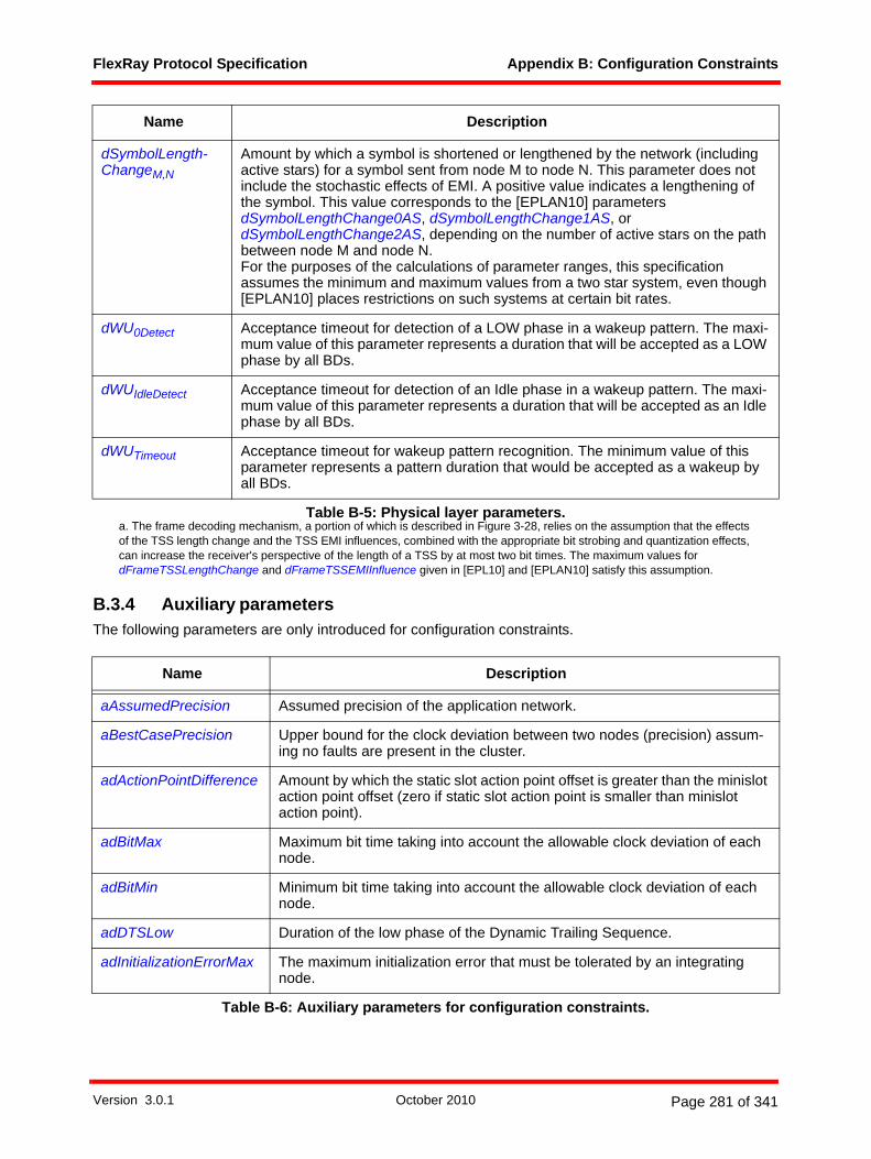
FlexRay Protocol Specification Appendix B: Configuration Constraints
B.3.4 Auxiliary parametersThe following parameters are only introduced for configuration constraints.
dSymbolLength-ChangeM,N
Amount by which a symbol is shortened or lengthened by the network (including active stars) for a symbol sent from node M to node N. This parameter does not include the stochastic effects of EMI. A positive value indicates a lengthening of the symbol. This value corresponds to the [EPLAN10] parameters dSymbolLengthChange0AS, dSymbolLengthChange1AS, or dSymbolLengthChange2AS, depending on the number of active stars on the path between node M and node N.For the purposes of the calculations of parameter ranges, this specification assumes the minimum and maximum values from a two star system, even though [EPLAN10] places restrictions on such systems at certain bit rates.
dWU0Detect Acceptance timeout for detection of a LOW phase in a wakeup pattern. The maxi-mum value of this parameter represents a duration that will be accepted as a LOW phase by all BDs.
dWUIdleDetect Acceptance timeout for detection of an Idle phase in a wakeup pattern. The maxi-mum value of this parameter represents a duration that will be accepted as an Idle phase by all BDs.
dWUTimeout Acceptance timeout for wakeup pattern recognition. The minimum value of this parameter represents a pattern duration that would be accepted as a wakeup by all BDs.
a. The frame decoding mechanism, a portion of which is described in Figure 3-28, relies on the assumption that the effects of the TSS length change and the TSS EMI influences, combined with the appropriate bit strobing and quantization effects, can increase the receiver's perspective of the length of a TSS by at most two bit times. The maximum values for dFrameTSSLengthChange and dFrameTSSEMIInfluence given in [EPL10] and [EPLAN10] satisfy this assumption.
Name Description
aAssumedPrecision Assumed precision of the application network.
aBestCasePrecision Upper bound for the clock deviation between two nodes (precision) assum-ing no faults are present in the cluster.
adActionPointDifference Amount by which the static slot action point offset is greater than the minislot action point offset (zero if static slot action point is smaller than minislot action point).
adBitMax Maximum bit time taking into account the allowable clock deviation of each node.
adBitMin Minimum bit time taking into account the allowable clock deviation of each node.
adDTSLow Duration of the low phase of the Dynamic Trailing Sequence.
adInitializationErrorMax The maximum initialization error that must be tolerated by an integrating node.
Table B-6: Auxiliary parameters for configuration constraints.
Name Description
Table B-5: Physical layer parameters.
Version 3.0.1 October 2010 Page 281 of 341

FlexRay Protocol Specification Appendix B: Configuration Constraints
adInternalRxDelay Additional implementation dependent delay on the receive path of the decoder up to the strobe point, i. e. an additional synchronization unit in front of the majority voting mechanism.It is in the responsibility of the semiconductor manufacturer to specify this implementation dependent value for its devices.
adLineDelay[Ch]M,N The contribution of the propagation delay attributed to the path lengths and the specific line delays T’0 of the various segments of the communication path between node M and node N (see [EPL10]). This value also includes delays attributed to the circuit board traces between the CC and the BD in both the transmitter and the receiver.
adMaxIdleDetectionDe-layAfterHIGH
Maximum time by which idle detection is delayed when ringing occurs after the transmission of a frame or WUDOP.
adMicrotickDistError Maximum time difference in a node arising from the integral (i.e., non-frac-tional) distribution of microticks across different macroticks vs. an ideal distri-bution that allowed fractional microticks. The value is based on the local microtick pdMicrotick.
adMicrotickMax Maximum microtick length of all microticks configured within a cluster.
adMicrotickMaxDistError Maximum time difference in a cluster arising from the integral (i.e., non-frac-tional) distribution of microticks across different macroticks vs. an ideal distri-bution that allowed fractional microticks. The value is based on the largest microtick in the cluster, adMicrotickMax.
adOffsetCorrection The duration in macroticks of the offset correction phase of the NIT.
adPropagationDelayMax Maximum propagation delay of a cluster.
adPropagationDelayMin Minimum propagation delay of a cluster.
adRemOffsetCalculation Time after the beginning of the NIT necessary to ensure completion of the offset correction calculation.
adRemRateCalculation Time after the beginning of the NIT necessary to ensure completion of the rate correction calculation.
adSymbolWindow-GuardInterval
Required period of inactivity to ensure that symbols transmitted in the sym-bol window are perceived by all receivers as beginning in the symbol win-dow.
adTxDyn Upper bound on the duration of a dynamic frame transmission.
adTxMax Maximum transmission duration of a CC (expressed in µs).
adTxStat Upper bound on the duration of a static frame transmission.
aFrameLength Frame length in bits of a frame including transmission start sequence, frame start sequence and frame end sequence but without idle detection time.
aFrameLengthDynamic Frame length in bits of a dynamic frame (see aFrameLength).
aFrameLengthStatic Frame length in bits of a static frame (see aFrameLength)
Name Description
Table B-6: Auxiliary parameters for configuration constraints.
Version 3.0.1 October 2010 Page 282 of 341
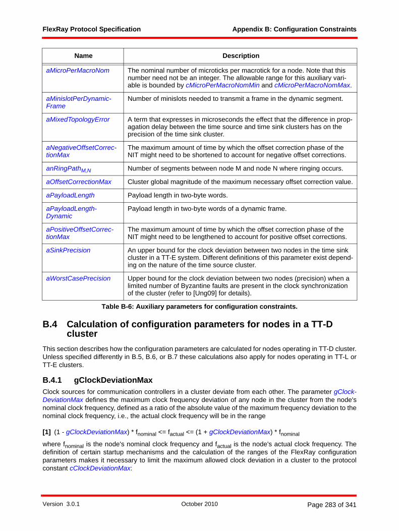
FlexRay Protocol Specification Appendix B: Configuration Constraints
B.4 Calculation of configuration parameters for nodes in a TT-D cluster
This section describes how the configuration parameters are calculated for nodes operating in TT-D cluster.Unless specified differently in B.5, B.6, or B.7 these calculations also apply for nodes operating in TT-L orTT-E clusters.
B.4.1 gClockDeviationMaxClock sources for communication controllers in a cluster deviate from each other. The parameter gClock-DeviationMax defines the maximum clock frequency deviation of any node in the cluster from the node'snominal clock frequency, defined as a ratio of the absolute value of the maximum frequency deviation to thenominal clock frequency, i.e., the actual clock frequency will be in the range
[1] (1 - gClockDeviationMax) * fnominal <= factual <= (1 + gClockDeviationMax) * fnominal
where fnominal is the node's nominal clock frequency and factual is the node's actual clock frequency. Thedefinition of certain startup mechanisms and the calculation of the ranges of the FlexRay configurationparameters makes it necessary to limit the maximum allowed clock deviation in a cluster to the protocolconstant cClockDeviationMax:
aMicroPerMacroNom The nominal number of microticks per macrotick for a node. Note that this number need not be an integer. The allowable range for this auxiliary vari-able is bounded by cMicroPerMacroNomMin and cMicroPerMacroNomMax.
aMinislotPerDynamic-Frame
Number of minislots needed to transmit a frame in the dynamic segment.
aMixedTopologyError A term that expresses in microseconds the effect that the difference in prop-agation delay between the time source and time sink clusters has on the precision of the time sink cluster.
aNegativeOffsetCorrec-tionMax
The maximum amount of time by which the offset correction phase of the NIT might need to be shortened to account for negative offset corrections.
anRingPathM,N Number of segments between node M and node N where ringing occurs.
aOffsetCorrectionMax Cluster global magnitude of the maximum necessary offset correction value.
aPayloadLength Payload length in two-byte words.
aPayloadLength-Dynamic
Payload length in two-byte words of a dynamic frame.
aPositiveOffsetCorrec-tionMax
The maximum amount of time by which the offset correction phase of the NIT might need to be lengthened to account for positive offset corrections.
aSinkPrecision An upper bound for the clock deviation between two nodes in the time sink cluster in a TT-E system. Different definitions of this parameter exist depend-ing on the nature of the time source cluster.
aWorstCasePrecision Upper bound for the clock deviation between two nodes (precision) when a limited number of Byzantine faults are present in the clock synchronization of the cluster (refer to [Ung09] for details).
Name Description
Table B-6: Auxiliary parameters for configuration constraints.
Version 3.0.1 October 2010 Page 283 of 341
FlexRay Protocol Specification Appendix B: Configuration Constraints
Constraint 1: 0 < gClockDeviationMax <= cClockDeviationMax
Note that physical layer effects such as asymmetric propagation delays of rising and falling edges may putadditional constraints on the maximum allowable clock deviation for certain physical layer topologies. Referto [EPLAN10] for additional details.
The calculation of the parameter ranges in this appendix is based on an assumption that gClockDevia-tionMax = cClockDeviationMax but for simplicity gClockDeviationMax is not included in the tables showingthe calculation of the parameter ranges.
B.4.2 Attainable precisionVarious error terms influence the attainable precision of the FlexRay clock synchronization algorithm (see[Ung09]). In order to choose proper configuration parameters it is necessary to know the attainable precisionof the application network. In order to simplify the equations the following calculations assume that theconfigurations for propagation delay compensation are configured to a value of identical time in all nodes(see section B.4.25 for details).
B.4.2.1 Propagation Delay
B.4.2.1.1 adInternalRxDelayAn implementation of the protocol may, for practical reasons, introduce an additional delay between the RxDpin of the communication controller and the circuits responsible for majority voting and bit strobing187 (seesection 3.2.4).
The allowed range of adInternalRxDelay for an implementation is
[2] cdInternalRxDelayMin <= adInternalRxDelay <= cdInternalRxDelayMax.
The parameter adInternalRxDelay is implementation dependent and, like other implementation dependentbehavior, must be specified in the documentation of an implementation.
B.4.2.1.2 adPropagationDelayMaxA parameter for the maximum propagation delay adPropagationDelayMax[µs] of the cluster is introducedwith
Constraint 2: adPropagationDelayMax[Ch][µs] = maxM,N( adLineDelay[Ch]M,N[µs] +
max( dCCTxD01[Ch]M[µs] + dBDTx01[Ch]M[µs] +
[µs] + dBDRx01[Ch]N[µs] + dCCRxD01[Ch]N[µs] ;
187 This could be, for example, an additional sample delay for evaluation of zVotedVal and setting zSampleCounter oran additional synchronization register prior to the voting registers (to avoid metastability effects).
dStarDelay01kk nStarPath Ch[ ]MN{ }∈
∑
Version 3.0.1 October 2010 Page 284 of 341

FlexRay Protocol Specification Appendix B: Configuration Constraints
dCCTxD10[Ch]M[µs] + dBDTx10[Ch]M[µs] +
[µs] + dBDRx10[Ch]N[µs] + dCCRxD10[Ch]N[µs] ) +
(1 samples + adInternalRxDelayN[samples] + cVotingDelay[samples] +
(cStrobeOffset[samples] - 1 samples) ) *
gdSampleClockPeriod[µs/samples] / (1 - gClockDeviationMax) )
[3] adPropagationDelayMax[µs] = max( adPropagationDelayMax[A][µs]; adPropagationDelayMax[B][µs] )
[4] adPropagationDelayMin[µs] = min( adPropagationDelayMin[A][µs]; adPropagationDelayMin[B][µs] )
• dCCTxD01[Ch]M and dBDTx01[Ch]M are the contributions to the propagation delay of a rising edgecaused by analog effects of the CC and BD of the transmitting node M on channel Ch.
• dCCTxD10[Ch]M and dBDTx10[Ch]M are the contributions to the propagation delay of a falling edgecaused by analog effects of the CC and BD of the transmitting node M on channel Ch.
• dBDRx01[Ch]N and dCCRxD01[Ch]N are the contributions to the propagation delay of a rising edgecaused by analog effects of the BD and CC of the receiving node N on channel Ch.
• dBDRx10[Ch]N and dCCRxD10[Ch]N are the contributions to the propagation delay of a falling edgecaused by analog effects of the BD and CC of the receiving node N on channel Ch
• dStarDelay01k is the propagation delay of a rising edge and dStarDelay10k is the propagation delayof a falling edge of star k.
• adLineDelay[Ch]M,N is the contribution of the propagation delay attributed to the path lengths andthe specific line delays T’0 of the various segments of the communication path between node M andnode N (see [EPL10]).188
• nStarPath[Ch]M,N is the number of active stars between node M and N on Channel Ch.• 1 sample is the delay between the edge occurring on the bus and the sampling edge.• adInternalRxDelayN[samples] is the implementation dependent delay on the receive path of the
decoder up to the strobe point of node N.• cVotingDelay ist the delay introduced by the majority voting.• cStrobeOffset - 1 sample is the delay introduced by the bit strobing process (BITSTRB).
For the purpose of deriving ranges for parameters within this appendix it is assumed that the portion of thepropagation delay caused by the physical layer and the analog effects of the FlexRay CC's involved incommunication is bounded by cPropagationDelayMax; this is true for all clusters adhering to [EPL10]. Thisleads to the following equation:
188 Any time delay introduced by the circuit board traces between the TxD output of the CC and the TxD input of the BD (on the transmitter) and the RxD output of the BD and the RxD input of the CC (on the receiver) are assumed to be included in the adLineDelay[Ch]M,N parameter. The contributions of these terms are expected to be small (on the order of 1-2 ns), and certainly smaller than the value implied for this contribution by the difference between cPropagationDelayMax and dPropagationDelayM,N.
dStarDelay10kk nStarPath Ch[ ]MN{ }∈
∑
Version 3.0.1 October 2010 Page 285 of 341
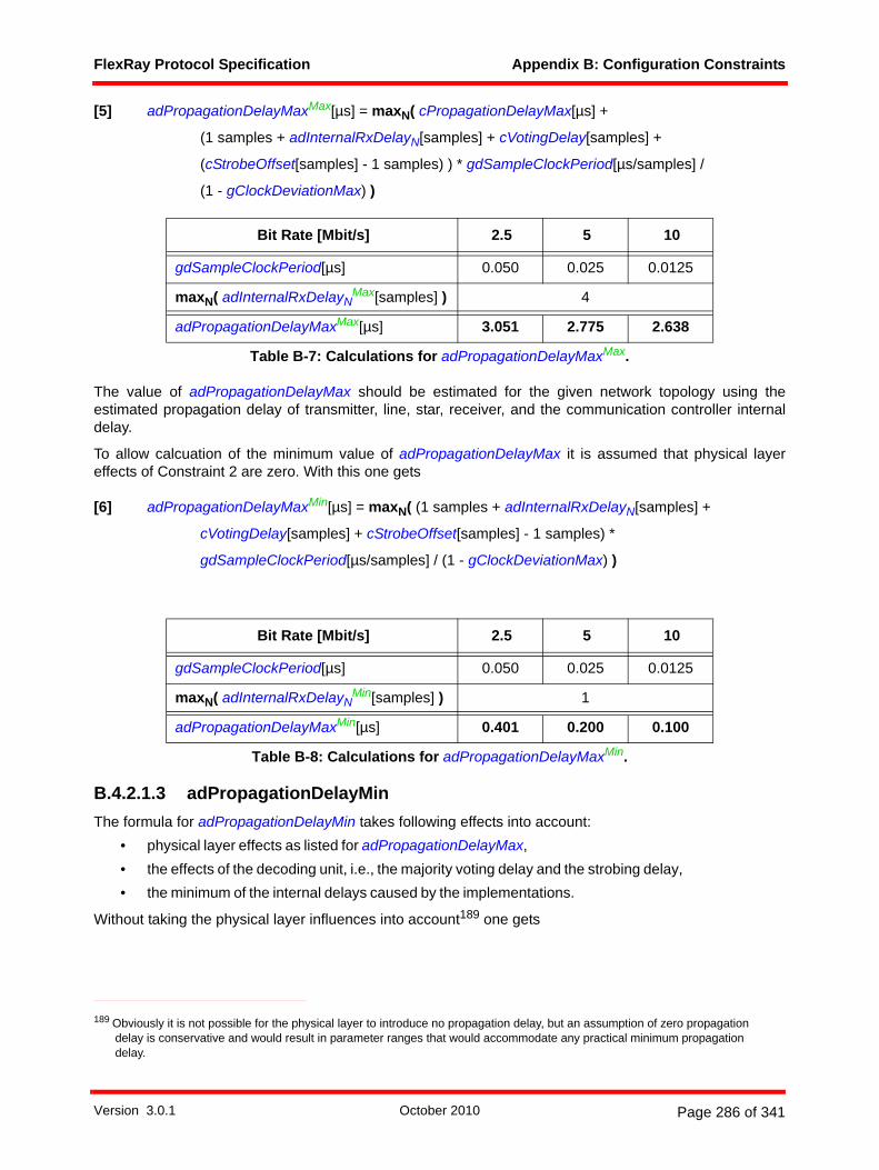
FlexRay Protocol Specification Appendix B: Configuration Constraints
[5] adPropagationDelayMaxMax[µs] = maxN( cPropagationDelayMax[µs] +
(1 samples + adInternalRxDelayN[samples] + cVotingDelay[samples] +
(cStrobeOffset[samples] - 1 samples) ) * gdSampleClockPeriod[µs/samples] /
(1 - gClockDeviationMax) )
The value of adPropagationDelayMax should be estimated for the given network topology using theestimated propagation delay of transmitter, line, star, receiver, and the communication controller internaldelay.
To allow calcuation of the minimum value of adPropagationDelayMax it is assumed that physical layereffects of Constraint 2 are zero. With this one gets
[6] adPropagationDelayMaxMin[µs] = maxN( (1 samples + adInternalRxDelayN[samples] +
cVotingDelay[samples] + cStrobeOffset[samples] - 1 samples) *
gdSampleClockPeriod[µs/samples] / (1 - gClockDeviationMax) )
B.4.2.1.3 adPropagationDelayMinThe formula for adPropagationDelayMin takes following effects into account:
• physical layer effects as listed for adPropagationDelayMax,• the effects of the decoding unit, i.e., the majority voting delay and the strobing delay,• the minimum of the internal delays caused by the implementations.
Without taking the physical layer influences into account189 one gets
Bit Rate [Mbit/s] 2.5 5 10
gdSampleClockPeriod[µs] 0.050 0.025 0.0125
maxN( adInternalRxDelayNMax[samples] ) 4
adPropagationDelayMaxMax[µs] 3.051 2.775 2.638
Table B-7: Calculations for adPropagationDelayMaxMax.
Bit Rate [Mbit/s] 2.5 5 10
gdSampleClockPeriod[µs] 0.050 0.025 0.0125
maxN( adInternalRxDelayNMin[samples] ) 1
adPropagationDelayMaxMin[µs] 0.401 0.200 0.100
Table B-8: Calculations for adPropagationDelayMaxMin.
189 Obviously it is not possible for the physical layer to introduce no propagation delay, but an assumption of zero propagation delay is conservative and would result in parameter ranges that would accommodate any practical minimum propagation delay.
Version 3.0.1 October 2010 Page 286 of 341

FlexRay Protocol Specification Appendix B: Configuration Constraints
Constraint 3: adPropagationDelayMin[µs] >=
minN( adInternalRxDelayN[samples] + cVotingDelay[samples] +
(cStrobeOffset[samples] - 1 samples) ) * gdSampleClockPeriod[µs/samples] /
(1 + gClockDeviationMax)
Taking the physical layer effects into account one gets
Constraint 4: adPropagationDelayMin[Ch][µs] = minM,N( adLineDelay[Ch]M,N[µs] +
min( dCCTxD01[Ch]M[µs] + dBDTx01[Ch]M[µs] +
[µs] + dBDRx01[Ch]N[µs] + dCCRxD01[Ch]N[µs] ;
dCCTxD10[Ch]M[µs] + dBDTx10[Ch]M[µs] +
[µs] + dBDRx10[Ch]N[µs] + dCCRxD10[Ch]N[µs] ) +
(adInternalRxDelayN[samples] + cVotingDelay[samples] +
(cStrobeOffset[samples] - 1 samples) ) *
gdSampleClockPeriod[µs/samples] / (1 + gClockDeviationMax) )
With Constraint 3 the minimum can be calculated to be
To allow calculation of the maximum value of adPropagationDelayMin it is assumed that the physical layereffects of Constraint 4 are bounded by the upper limit of cPropagationDelayMax. With this one gets:
Bit Rate [Mbit/s] 2.5 5 10
gdSampleClockPeriod[µs] 0.050 0.025 0.0125
minN( adInternalRxDelayNMin[samples] ) 1
adPropagationDelayMinMin[µs] 0.349 0.175 0.087
Table B-9: Calculations for adPropagationDelayMinMin.
dStarDelay01kk nStarPath Ch[ ]MN{ }∈
∑
dStarDelay10kk nStarPath Ch[ ]MN{ }∈
∑
Version 3.0.1 October 2010 Page 287 of 341

FlexRay Protocol Specification Appendix B: Configuration Constraints
[7] adPropagationDelayMinMax[µs] = minN( cPropagationDelayMax[µs] +
(adInternalRxDelayN[samples] + cVotingDelay[samples] +
cStrobeOffset[samples] - 1 samples) *
gdSampleClockPeriod[µs/samples] / (1 + gClockDeviationMax) )
B.4.2.2 Microtick Distribution ErrorThe macrotick generation process generates macrotick events, which are naturally restricted to a discretegrid determined by the local microtick clock. Compared to an ideal macrotick generation process, whichwould be able to generate events at any point in time, the restriction to the microtick grid introduces adiscretization error. The macrotick generation process is designed to prevent the accumulation of thisdiscretization error; it is assured that the duration of any number of consecutive, discrete macroticks onlydeviates from the duration of the corresponding ideal, non-discrete macroticks by at most the duration of asingle microtick. This single microtick must be taken into consideration when converting an amount of realtime into a number of discrete local macroticks of a node.
The auxiliary variable adMicrotickDistError is introduced to capture the effect of the discretization of themacrotick clock in a given node:
[8] adMicrotickDistError[µs] = pdMicrotick[µs] / (1 - gClockDeviationMax)
The values for adMicrotickDistError for various microtick durations are calculated in table B-11.
The auxiliary variable adMicrotickMaxDistError is introduced to capture the effect of the discretization of themacrotick clocks in a cluster, and is therefore based on the longest microtick in a cluster:
[9] adMicrotickMaxDistError[µs] = adMicrotickMax[µs] / (1 - gClockDeviationMax)
The values for adMicrotickMaxDistError for various microtick durations are calculated in table B-12. Thesevalues are used in the calculations of parameter ranges but are not specifically included in the tables.
Bit Rate [Mbit/s] 2.5 5 10
gdSampleClockPeriod[µs] 0.050 0.025 0.0125
minN( adInternalRxDelayNMax[samples] ) 4
adPropagationDelayMinMax[µs] 2.999 2.750 2.625
Table B-10: Calculations for adPropagationDelayMinMax.
pdMicrotick[µs] 0.050 0.025 0.0125
adMicrotickDistError[µs] 0.050075 0.025038 0.012519
Table B-11: Calculations for adMicrotickDistError.
adMicrotickMax[µs] 0.050 0.025 0.0125
adMicrotickMaxDistError[µs] 0.050075 0.025038 0.012519
Table B-12: Calculations for adMicrotickMaxDistError.
Version 3.0.1 October 2010 Page 288 of 341
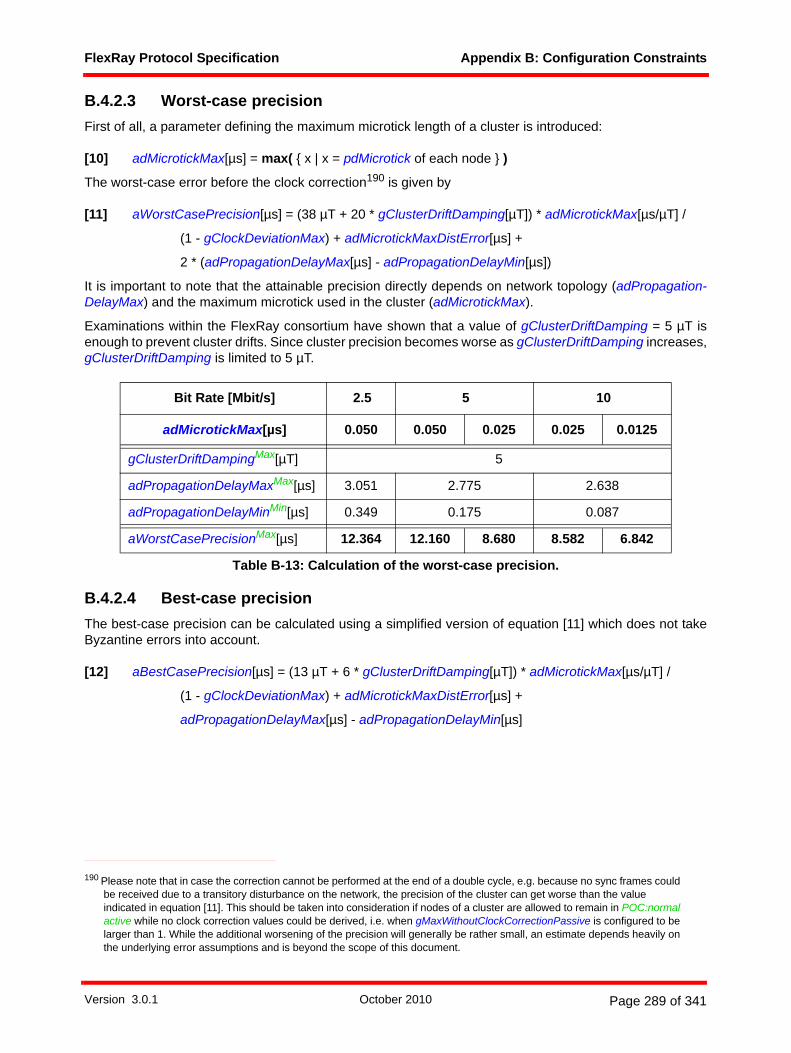
FlexRay Protocol Specification Appendix B: Configuration Constraints
B.4.2.3 Worst-case precisionFirst of all, a parameter defining the maximum microtick length of a cluster is introduced:
[10] adMicrotickMax[µs] = max( { x | x = pdMicrotick of each node } )
The worst-case error before the clock correction190 is given by
[11] aWorstCasePrecision[µs] = (38 µT + 20 * gClusterDriftDamping[µT]) * adMicrotickMax[µs/µT] /
(1 - gClockDeviationMax) + adMicrotickMaxDistError[µs] +
2 * (adPropagationDelayMax[µs] - adPropagationDelayMin[µs])
It is important to note that the attainable precision directly depends on network topology (adPropagation-DelayMax) and the maximum microtick used in the cluster (adMicrotickMax).
Examinations within the FlexRay consortium have shown that a value of gClusterDriftDamping = 5 µT isenough to prevent cluster drifts. Since cluster precision becomes worse as gClusterDriftDamping increases,gClusterDriftDamping is limited to 5 µT.
B.4.2.4 Best-case precisionThe best-case precision can be calculated using a simplified version of equation [11] which does not takeByzantine errors into account.
[12] aBestCasePrecision[µs] = (13 µT + 6 * gClusterDriftDamping[µT]) * adMicrotickMax[µs/µT] /
(1 - gClockDeviationMax) + adMicrotickMaxDistError[µs] +
adPropagationDelayMax[µs] - adPropagationDelayMin[µs]
190 Please note that in case the correction cannot be performed at the end of a double cycle, e.g. because no sync frames could be received due to a transitory disturbance on the network, the precision of the cluster can get worse than the value indicated in equation [11]. This should be taken into consideration if nodes of a cluster are allowed to remain in POC:normal active while no clock correction values could be derived, i.e. when gMaxWithoutClockCorrectionPassive is configured to be larger than 1. While the additional worsening of the precision will generally be rather small, an estimate depends heavily on the underlying error assumptions and is beyond the scope of this document.
Bit Rate [Mbit/s] 2.5 5 10
adMicrotickMax[µs] 0.050 0.050 0.025 0.025 0.0125
gClusterDriftDampingMax[µT] 5
adPropagationDelayMaxMax[µs] 3.051 2.775 2.638
adPropagationDelayMinMin[µs] 0.349 0.175 0.087
aWorstCasePrecisionMax[µs] 12.364 12.160 8.680 8.582 6.842
Table B-13: Calculation of the worst-case precision.
Version 3.0.1 October 2010 Page 289 of 341

FlexRay Protocol Specification Appendix B: Configuration Constraints
It is not possible to reach a precision better than calculated in equation [12].
B.4.2.5 Assumed precisionAn assumed precision of the cluster, aAssumedPrecision is introduced. The aAssumedPrecision parameteris necessary to derive additional constraints on other timing parameters. This parameter is given by
Constraint 5: aAssumedPrecision[µs] >= aBestCasePrecision[µs]
For purposes of configuration of the cluster, it is suggested that the assumed precision be set equal to theworst case precision:
[13] aAssumedPrecision[µs] = aWorstCasePrecision[µs]
Parameter ranges in this specification are calculated assuming that the maximum and minimum value ofaAssumedPrecision are aWorstCasePrecisionMax and aBestCasePrecisionMin, respectively.
B.4.3 RingingDue to physical layer effects, a node may experience a period of instability on the physical layer after theend of a transmission. During this period the bus level may exceed the thresholds for detecting active lowand active high and may switch multiple times between the active low and active high state, ending on eitherof these states. This is called ringing.
The duration of ringing depends mainly on the topology, especially on the number of active stars. For detailsrefer to section 2.17 in [EPLAN10].
From the perspective of a communication controller ringing can happen after the end of a frame or symboltransmission and would show up as one or multiple transitions between LOW and HIGH on the RxD input.
Ringing has various effects - some of them are listed below:• After the reception of a FES high bit, ringing delays the start of the idle phase.• After the reception of a DTS high bit, ringing delays the start of the idle phase. Ringing can trigger
additional potential idle start signals sent to the MAC process, which has an influence in case of adynamic frame decoding error.
• After the reception of a symbol, ringing delays the start of the idle phase.• After the transmission of a WUS low phase, ringing may appear to the transmitting node as if a
collision with another node's WUS low phase had happened.
When ringing occurs after a transmission that ends on a high bit (which is the case for frames andWUDOPs), from the perspective of the physical layer the start of idle detection is delayed by the duration of
Bit Rate [Mbit/s] 2.5 5 10
adMicrotickMax[µs] 0.050 0.050 0.025 0.025 0.0125
gClusterDriftDampingMin[µT] 0
min( adPropagationDelayMax[µs] - adPropagationDelayMin[µs] ) 0
aBestCasePrecisionMin[µs] 0.701 0.701 0.351 0.351 0.175
Table B-14: Calculation of the best-case precision.
Version 3.0.1 October 2010 Page 290 of 341
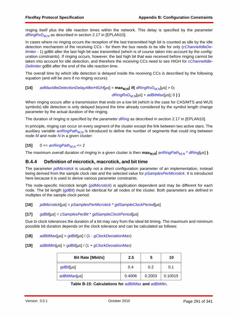
FlexRay Protocol Specification Appendix B: Configuration Constraints
ringing itself plus the idle reaction times within the network. This delay is specified by the parameterdRingRxDM,N as described in section 2.17 in [EPLAN10].
In cases where no ringing occurs the reception of the last transmitted high bit is counted as idle by the idledetection mechanism of the receiving CCs - for them the bus needs to be idle for only (cChannelIdleDe-limiter - 1) gdBit after the last high bit was transmitted (which is of course taken into account by the config-uration constraints). If ringing occurs, however, the last high bit that was received before ringing cannot betaken into account for idle detection, and therefore the receiving CCs need to see HIGH for cChannelIdle-Delimiter gdBit after the end of the idle reaction time.
The overall time by which idle detection is delayed inside the receiving CCs is described by the followingequation (and will be zero if no ringing occurs):
[14] adMaxIdleDetectionDelayAfterHIGH[µs] = maxM,N( if( dRingRxDM,N[µs] > 0;
dRingRxDM,N[µs] + adBitMax[µs]; 0 ) )
When ringing occurs after a transmission that ends on a low bit (which is the case for CAS/MTS and WUSsymbols) idle detection is only delayed beyond the time already considered by the symbol length changeparameter by the actual duration of the ringing.
The duration of ringing is specified by the parameter dRing as described in section 2.17 in [EPLAN10].
In principle, ringing can occur on every segment of the cluster except the link between two active stars. Theauxiliary variable anRingPathM,N is introduced to define the number of segments that could ring betweennode M and node N in a given cluster:
[15] 0 <= anRingPathM,N <= 2
The maximum overall duration of ringing in a given cluster is then maxM,N( anRingPathM,N * dRing[µs] ).
B.4.4 Definition of microtick, macrotick, and bit timeThe parameter pdMicrotick is usually not a direct configuration parameter of an implementation, insteadbeing derived from the sample clock rate and the selected value for pSamplesPerMicrotick. It is introducedhere because it is used to derive various parameter constraints.
The node-specific microtick length (pdMicrotick) is application dependent and may be different for eachnode. The bit length (gdBit) must be identical for all nodes of the cluster. Both parameters are defined inmultiples of the sample clock period.
[16] pdMicrotick[µs] = pSamplesPerMicrotick * gdSampleClockPeriod[µs]
[17] gdBit[µs] = cSamplesPerBit * gdSampleClockPeriod[µs]
Due to clock tolerances the duration of a bit may vary from the ideal bit timing. The maximum and minimumpossible bit duration depends on the clock tolerance and can be calculated as follows:
[18] adBitMax[µs] = gdBit[µs] / (1 - gClockDeviationMax)
[19] adBitMin[µs] = gdBit[µs] / (1 + gClockDeviationMax)
Bit Rate [Mbit/s] 2.5 5 10
gdBit[µs] 0.4 0.2 0.1
adBitMax[µs] 0.4006 0.2003 0.10015
Table B-15: Calculations for adBitMax and adBitMin.
Version 3.0.1 October 2010 Page 291 of 341

FlexRay Protocol Specification Appendix B: Configuration Constraints
Table B-16 shows the possible microtick lengths depending on pSamplesPerMicrotick and gdSampleClock-Period. An implementation shall support all of the combinations shown in this table.
Table B-17 shows representative values of the nominal macrotick length gdMacrotick that can be achievedwith various microtick durations while keeping both aMicroPerMacroNom and gdMacrotick within theirallowable ranges. The actual macrotick duration used in a system need not be selected from those listed inthe table, and need not even use integral values for aMicroPerMacroNom, but aMicroPerMacroNom mustbe in the range of 40 to 240 microticks per macrotick, gdMacrotick must be in the range of 1 to 6 micro-seconds, and Constraint 7 must be fulfilled.
The desired nominal macrotick length gdMacrotick in µs can be chosen to be less than, greater than, orequal to the assumed precision. In all cases the macrotick length must fulfill the following constraint:
Constraint 6: cdMinMTNom[µs] <= gdMacrotick[µs] <= cdMaxMTNom[µs]
Depending on the desired macrotick length the following additional constraint must be met.
Constraint 7: gdMacrotick[µs] >= cMicroPerMacroNomMin[µT] * pdMicrotick[µs/µT]
A parameter describing the nominal number of microticks in a macrotick is given by
[20] aMicroPerMacroNom[µT/MT] = gdMacrotick[µs/MT] / pdMicrotick[µs/µT]
adBitMin[µs] 0.3994 0.1997 0.09985
Bit Rate [Mbit/s] 2.5 5 10
gdSampleClockPeriod[µs] 0.050 0.025 0.0125
pSamplesPerMicrotick 1 2 1 2 1
pdMicrotick[µs] 0.050 0.050 0.025 0.025 0.0125
Table B-16: pdMicrotick depending on pSamplesPerMicrotick and gdSampleClockPeriod.
aMicroPer-MacroNom
pdMicrotick[µs]
0.0125 0.025 0.050
40 - 1 2
60 - 1.5 3
80 1 2 4
120 1.5 3 6
240 3 6 -
Table B-17: Examples of gdMacrotick as a function of aMicroPerMacroNom and pdMicrotick.
Bit Rate [Mbit/s] 2.5 5 10
Table B-15: Calculations for adBitMax and adBitMin.
Version 3.0.1 October 2010 Page 292 of 341

FlexRay Protocol Specification Appendix B: Configuration Constraints
For gdMacrotick there is an additional constraint because of the startup procedure and pMicroInitialOffset:
Constraint 8: gdMacrotick[µs] <= ((aFrameLengthStatic[gdBit] - cdFES[gdBit]) * gdBit[µs/gdBit] -
gdSampleClockPeriod[µs] + adPropagationDelayMin[µs]) *
((1 - gClockDeviationMax) / (1 + gClockDeviationMax))
Constraint 8 is necessary to ensure that events occur in the order required by the mechanism described inFigure 8-11, in particular, that at least one macrotick length must pass between the primary time referencepoint and the valid odd startup frame on A signal in order for the continue integration on A signal to properlystart the macrotick generation. Note, however, that fulfillment of this constraint is automatic because of themaximum macrotick length allowed by the protocol and the allowed values of minimum frame length, bitduration, and the other parameters in the constraint.
B.4.5 adInitializationErrorMaxThe maximum initialization error that must be tolerated by an integrating node depends primarily on theassumed precision and the propagation delay. Consider the following assumptions:
• The clocks of two nodes may have an offset of up to the assumed precision. • An external offset correction might need to be applied.• The received frames might be received with the maximum propagation delay of which only the
minimal possible propagation delay is compensated by the local delay compensation.
Constraint 9: adInitializationErrorMax[µs] >= aAssumedPrecision[µs] + gExternOffsetCorrection[µs] +
adPropagationDelayMax[µs] - adPropagationDelayMin[µs]
In general, adInitializationErrorMax should be chosen using the equality constraint. Under certain excep-tional circumstances, however, this choice of parameter could result in a slight delay of startup. The systemdesigner may choose to reduce this probability by selecting a somewhat larger value for adInitialization-ErrorMax, and thus the previous constraint is expressed as an inequality. Note that increasing the value ofadInitializationErrorMax may have a significant impact on the required action point offset, and therefore therequired static slot size.
Bit Rate [Mbit/s] 2.5 5 10
adMicrotickMax[µs] 0.050 0.050 0.025 0.025 0.0125
aAssumedPrecisionMin[µs] = aBestCasePrecisionMin[µs] 0.701 0.701 0.351 0.351 0.175
gExternOffsetCorrectionMin[µs] 0
adPropagationDelayMax[µs] - adPropagationDelayMin[µs] 0
adInitializationErrorMaxMin[µs] 0.701 0.701 0.351 0.351 0.175
aAssumedPrecisionMax[µs] = aWorstCasePrecisionMax[µs] 12.364 12.160 8.680 8.582 6.842
gExternOffsetCorrectionMax[µs] 0.35
Table B-18: Calculations for adInitializationErrorMax.
Version 3.0.1 October 2010 Page 293 of 341

FlexRay Protocol Specification Appendix B: Configuration Constraints
B.4.6 pdAcceptedStartupRangeConsider the following assumptions:
• During integration a clock synchronization error greater than the assumed precision may occur andbe acceptable.
Constraint 10: pdAcceptedStartupRange[µT] >= ceil( (aAssumedPrecision[µs] + adInitializationErrorMax[µs]) /
(pdMicrotick[µs/µT] / (1 + gClockDeviationMax)) )
The lower bound of pdAcceptedStartupRange is given by the calculation in a TT-D cluster and the upperbound by the calculation in a TT-E cluster (see section B.7.13, table B-49). As a result, the parameterpdAcceptedStartupRange must be configurable over a range of 29 to 2743 µT.
B.4.7 pClusterDriftDampingConsider the following assumptions:
• The drift damping factor gClusterDriftDamping is defined in multiples of the longest microtickadMicrotickMax within the cluster:
gClusterDriftDamping[µT] = n * 1 µT with n = 0, 1, 2, ..., 5.
adPropagationDelayMinMin[µs] 0.349 0.175 0.087
adPropagationDelayMaxMax[µs] 3.051 2.775 2.638
adInitializationErrorMaxMax[µs] 15.416 15.110 11.630 11.483 9.743
Bit Rate [Mbit/s] 2.5 5 10
adMicrotickMax[µs] 0.050 0.050 0.025 0.025 0.0125
aAssumedPrecisionMin[µs] = aBestCasePrecisionMin[µs] 0.701 0.701 0.351 0.351 0.175
adInitializationErrorMaxMin[µs] 0.701 0.701 0.351 0.351 0.175
pdMicrotickMax[µs] 0.050 0.050 0.025 0.025 0.0125
pdAcceptedStartupRangeMin[µT] 29 29 29 29 29
aAssumedPrecisionMax[µs] = aWorstCasePrecisionMax[µs] 12.364 12.160 8.680 8.582 6.842
adInitializationErrorMaxMax[µs] 15.416 15.110 11.630 11.483 9.743
pdMicrotickMin[µs] 0.050 0.025 0.0125
pdAcceptedStartupRangeMax[µT] 557 1093 814 1608 1329
Table B-19: Calculations for pdAcceptedStartupRange.
Bit Rate [Mbit/s] 2.5 5 10
adMicrotickMax[µs] 0.050 0.050 0.025 0.025 0.0125
Table B-18: Calculations for adInitializationErrorMax.
Version 3.0.1 October 2010 Page 294 of 341

FlexRay Protocol Specification Appendix B: Configuration Constraints
• The maximum microtick of a cluster adMicrotickMax is a multiple m of each node’s local microtickpdMicrotick.
adMicrotickMax = m * pdMicrotick with m = 1, 2 (see pSamplesPerMicrotick).• The local drift damping pClusterDriftDamping is calculated by
Constraint 11: pClusterDriftDamping[µT] <= gClusterDriftDamping[µT] * (adMicrotickMax[µs/µT] /
pdMicrotick[µs/µT])
Constraint 11 should be treated as a recommendation. In practice it is expected that the drift damping factoris chosen such that
The upper limit of pClusterDriftDamping is given by adMicrotickMax/pdMicrotick = 2. Therefore, pCluster-DriftDampingMax = 2 * 5 µT = 10 µT, and thus the parameter pClusterDriftDamping must be configurableover a range of 0 to 10 µT.
B.4.8 gdActionPointOffsetConsider the following assumptions:
• The action point offset should be greater than the assumed precision.• A minimum propagation delay of the network as seen by the local node is given by adPropagation-
DelayMin[µs].
Constraint 12: gdActionPointOffset[MT] >= ceil( (aAssumedPrecision[µs] - adPropagationDelayMin[µs]) /
(gdMacrotick[µs/MT] / (1 + gClockDeviationMax)) )
In order to prevent the possibility of the creation of cliques191 during startup an additional safety margin mustbe added. In this case Constraint 13 replaces Constraint 12.
Constraint 13: gdActionPointOffset[MT] >= ceil( (2 * aAssumedPrecision[µs] - adPropagationDelayMin[µs] +
2 * adInitializationErrorMax[µs]) / (gdMacrotick[µs/MT] / (1 + gClockDeviationMax)) )
191 Clique formation may be possible if more than two coldstart nodes are configured in the cluster under specific error scenarios.
Bit Rate [Mbit/s] 2.5 5 10
adMicrotickMax[µs] 0.050 0.050 0.025 0.025 0.0125
aAssumedPrecisionMax[µs] = aWorstCasePrecisionMax[µs] 12.364 12.160 8.680 8.582 6.842
adPropagationDelayMinMin[µs] 0.349 0.175 0.087
adInitializationErrorMaxMax[µs] 15.416 15.110 11.630 11.483 9.743
Table B-20: Calculations for gdActionPointOffset.
pClusterDriftDamping gClusterDriftDamping≈
Version 3.0.1 October 2010 Page 295 of 341

FlexRay Protocol Specification Appendix B: Configuration Constraints
In order to determine the configuration range of gdActionPointOffset an additional margin of safety is takeninto account. As a result, the parameter gdActionPointOffset must be configurable over a range of 1 to 63MT. This also allows a static slot design with additional safety margin, i.e. the action point of the static slotsincludes a safety margin beyond the achievable precision of the cluster.
B.4.9 gdMinislotActionPointOffsetConsider the following assumptions:
• The minislot action point gdMinislotActionPointOffset is greater than or equal to the assumedprecision aAssumedPrecision reduced by the minimum propagation delay adPropagationDelayMinof the network.
Constraint 14: gdMinislotActionPointOffset[MT] >= ceil( (aAssumedPrecision[µs] - adPropagationDelayMin[µs]) /
(gdMacrotick[µs/MT] / (1 + gClockDeviationMax)) )
gdMinislotActionPointOffset shall be configurable in a range of 1 to 31 MT.
gdMinislotActionPointOffset can be independently configured from gdActionPointOffset. This is useful if thestatic segment design includes an additional safety margin that is not required in the dynamic segment. Theindependent choice of gdMinislotActionPointOffset allows increased throughput in the dynamic segment.
B.4.10 gdSymbolWindowActionPointOffsetConsider the following assumptions:
• The symbol window action point gdSymbolWindowActionPointOffset is greater than or equal to theassumed precision aAssumedPrecision reduced by the minimum propagation delay adPropaga-tionDelayMin of the network.
• The symbol window action point gdSymbolWindowActionPointOffset is greater than or equal to theaction point of the preceding segment.
• At least gdWakeupRxIdle bit times without activity on the bus shall take place before the start of aWUDOP transmission.
Constraint 15: adSymbolWindowGuardInterval[MT] >= ceil( (aAssumedPrecision[µs] -
adPropagationDelayMin[µs]) / (gdMacrotick[µs/MT] / ( 1 + gClockDeviationMax)) )
For the purposes of the calculation of parameter ranges it is assumed that adSymbolWindowGuardIntervaltakes on values within a range of 1 to 31 MT.
gdMacrotickMin[µs] 2 2 1 1 1
gdActionPointOffsetMax[MT](Constraint 12) 7 7 9 9 7
gdActionPointOffsetMax[MT](Constraint 13) 28 28 41 41 34
Bit Rate [Mbit/s] 2.5 5 10
adMicrotickMax[µs] 0.050 0.050 0.025 0.025 0.0125
Table B-20: Calculations for gdActionPointOffset.
Version 3.0.1 October 2010 Page 296 of 341
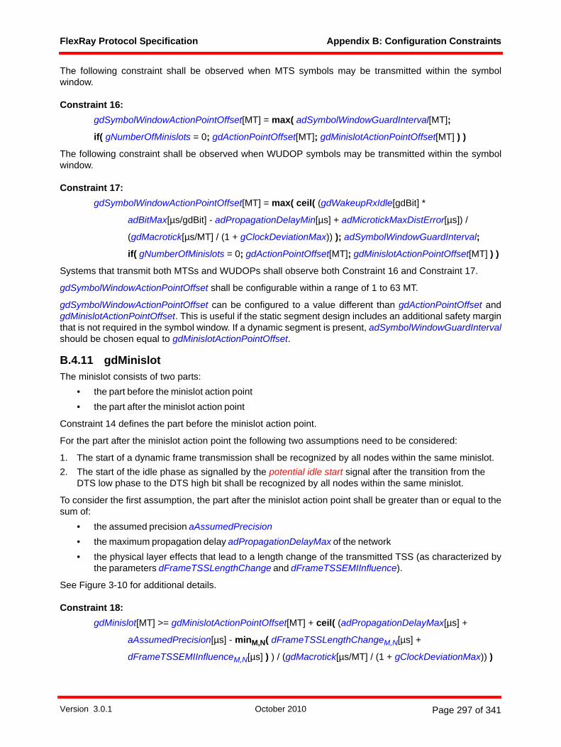
FlexRay Protocol Specification Appendix B: Configuration Constraints
The following constraint shall be observed when MTS symbols may be transmitted within the symbolwindow.
Constraint 16: gdSymbolWindowActionPointOffset[MT] = max( adSymbolWindowGuardInterval[MT];
if( gNumberOfMinislots = 0; gdActionPointOffset[MT]; gdMinislotActionPointOffset[MT] ) )
The following constraint shall be observed when WUDOP symbols may be transmitted within the symbolwindow.
Constraint 17: gdSymbolWindowActionPointOffset[MT] = max( ceil( (gdWakeupRxIdle[gdBit] *
adBitMax[µs/gdBit] - adPropagationDelayMin[µs] + adMicrotickMaxDistError[µs]) /
(gdMacrotick[µs/MT] / (1 + gClockDeviationMax)) ); adSymbolWindowGuardInterval;
if( gNumberOfMinislots = 0; gdActionPointOffset[MT]; gdMinislotActionPointOffset[MT] ) )
Systems that transmit both MTSs and WUDOPs shall observe both Constraint 16 and Constraint 17.
gdSymbolWindowActionPointOffset shall be configurable within a range of 1 to 63 MT.
gdSymbolWindowActionPointOffset can be configured to a value different than gdActionPointOffset andgdMinislotActionPointOffset. This is useful if the static segment design includes an additional safety marginthat is not required in the symbol window. If a dynamic segment is present, adSymbolWindowGuardIntervalshould be chosen equal to gdMinislotActionPointOffset.
B.4.11 gdMinislotThe minislot consists of two parts:
• the part before the minislot action point• the part after the minislot action point
Constraint 14 defines the part before the minislot action point.
For the part after the minislot action point the following two assumptions need to be considered:
1. The start of a dynamic frame transmission shall be recognized by all nodes within the same minislot.2. The start of the idle phase as signalled by the potential idle start signal after the transition from the
DTS low phase to the DTS high bit shall be recognized by all nodes within the same minislot.
To consider the first assumption, the part after the minislot action point shall be greater than or equal to thesum of:
• the assumed precision aAssumedPrecision• the maximum propagation delay adPropagationDelayMax of the network• the physical layer effects that lead to a length change of the transmitted TSS (as characterized by
the parameters dFrameTSSLengthChange and dFrameTSSEMIInfluence).
See Figure 3-10 for additional details.
Constraint 18: gdMinislot[MT] >= gdMinislotActionPointOffset[MT] + ceil( (adPropagationDelayMax[µs] +
aAssumedPrecision[µs] - minM,N( dFrameTSSLengthChangeM,N[µs] +
dFrameTSSEMIInfluenceM,N[µs] ) ) / (gdMacrotick[µs/MT] / (1 + gClockDeviationMax)) )
Version 3.0.1 October 2010 Page 297 of 341

FlexRay Protocol Specification Appendix B: Configuration Constraints
To consider the second assumption, the part after the minislot action point shall be greater than or equal tothe sum of:
• the assumed precision aAssumedPrecision• the maximum propagation delay adPropagationDelayMax of the network• the overall effect of ringing if present
Constraint 19: gdMinislot[MT] >= gdMinislotActionPointOffset[MT] + ceil( (adPropagationDelayMax[µs] +
aAssumedPrecision[µs] + adMaxIdleDetectionDelayAfterHIGH[µs]) /
(gdMacrotick[µs/MT] / (1 + gClockDeviationMax)) )
With the assumptions for gdMinislotActionPointOffset given in section B.4.9, and allowing for a margin ofsafety, the parameter gdMinislot must be configurable over a range of 2 to 63 MT.
In addition to the previous constraints, it is possible that for certain system configurations the parametergdMinislot has an additional constraint related to the parameter gdIgnoreAfterTx. Refer to section B.4.37 foradditional details.
B.4.12 gdStaticSlotConsider the following assumptions:
• A frame consists of at least gdTSSTransmitter, cdFSS, 80 gdBit of header and trailer (withgPayloadLengthStatic = 0), and cdFES.
• Each two-byte payload data word adds a duration equal to 2 * (8 gdBit + cdBSS[gdBit]) = 20 gdBit.
The length of a frame is given by:
[21] aFrameLength[gdBit] = gdTSSTransmitter[gdBit] + cdFSS[gdBit] + 80 gdBit +
aPayloadLength[two-byte word] * 20 gdBit / two-byte word + cdFES[gdBit]
Substituting the length of a static frame for aPayloadLength results in:
[22] aFrameLengthStatic = aFrameLength with aPayloadLength = gPayloadLengthStatic
In addition to the frame length, the following effects must also be considered: • The length of a static slot, expressed as a number of macroticks, depends on the maximum clock
deviation (gClockDeviationMax) and the minimum duration of a macrotick.• The effects of system precision may be taken into account by including gdActionPointOffset before
and after frame transmission.• An idle detection time of cChannelIdleDelimiter must be considered. For the purposes of this
constraint, the idle detection time must be reduced by the duration of the high bit of the FES as thisappears to the receiver as part of the idle detection.
• The maximum and minimum propagation delays of the cluster must also be taken into account.• The effects of ringing must be taken into account by adding a parameter that will be zero if no ringing
occurs.
Using equation [21] and [22] the minimum static slot length for systems can be calculated by Constraint 20:
Version 3.0.1 October 2010 Page 298 of 341
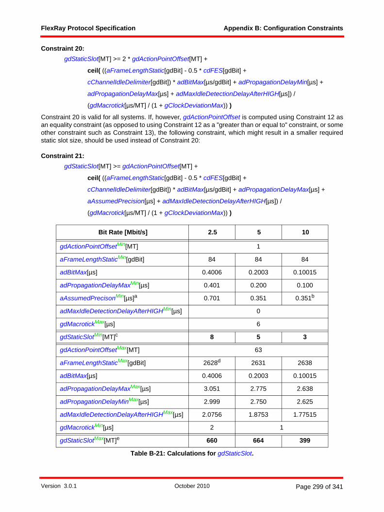
FlexRay Protocol Specification Appendix B: Configuration Constraints
Constraint 20: gdStaticSlot[MT] >= 2 * gdActionPointOffset[MT] +
ceil( ((aFrameLengthStatic[gdBit] - 0.5 * cdFES[gdBit] +
cChannelIdleDelimiter[gdBit]) * adBitMax[µs/gdBit] + adPropagationDelayMin[µs] +
adPropagationDelayMax[µs] + adMaxIdleDetectionDelayAfterHIGH[µs]) /
(gdMacrotick[µs/MT] / (1 + gClockDeviationMax)) )
Constraint 20 is valid for all systems. If, however, gdActionPointOffset is computed using Constraint 12 asan equality constraint (as opposed to using Constraint 12 as a "greater than or equal to" constraint, or someother constraint such as Constraint 13), the following constraint, which might result in a smaller requiredstatic slot size, should be used instead of Constraint 20:
Constraint 21: gdStaticSlot[MT] >= gdActionPointOffset[MT] +
ceil( ((aFrameLengthStatic[gdBit] - 0.5 * cdFES[gdBit] +
cChannelIdleDelimiter[gdBit]) * adBitMax[µs/gdBit] + adPropagationDelayMax[µs] +
aAssumedPrecision[µs] + adMaxIdleDetectionDelayAfterHIGH[µs]) /
(gdMacrotick[µs/MT] / (1 + gClockDeviationMax)) )
Bit Rate [Mbit/s] 2.5 5 10
gdActionPointOffsetMin[MT] 1
aFrameLengthStaticMin[gdBit] 84 84 84
adBitMax[µs] 0.4006 0.2003 0.10015
adPropagationDelayMaxMin[µs] 0.401 0.200 0.100
aAssumedPrecisonMin[µs]a 0.701 0.351 0.351b
adMaxIdleDetectionDelayAfterHIGHMin[µs] 0
gdMacrotickMax[µs] 6
gdStaticSlotMin[MT]c 8 5 3
gdActionPointOffsetMax[MT] 63
aFrameLengthStaticMax[gdBit] 2628d 2631 2638
adBitMax[µs] 0.4006 0.2003 0.10015
adPropagationDelayMaxMax[µs] 3.051 2.775 2.638
adPropagationDelayMinMax[µs] 2.999 2.750 2.625
adMaxIdleDetectionDelayAfterHIGHMax[µs] 2.0756 1.8753 1.77515
gdMacrotickMin[µs] 2 1
gdStaticSlotMax[MT]e 660 664 399
Table B-21: Calculations for gdStaticSlot.
Version 3.0.1 October 2010 Page 299 of 341

FlexRay Protocol Specification Appendix B: Configuration Constraints
As a result, the parameter gdStaticSlot must be configurable over a range of 3 to 664 MT.
In addition to the previous constraints, it is possible that for certain system configurations the parametergdStaticSlot has an additional constraint related to the parameter gdIgnoreAfterTx. Refer to section B.4.37for additional details.
B.4.13 gdSymbolWindowConsider the following assumptions:
• The length of an MTS symbol is defined by cdCAS192.• An MTS symbol is sent with a leading transmission start sequence. The symbol window takes this
into account by using gdTSSTransmitter + cdCAS.• The influence of the precision is taken into account by gdSymbolWindowActionPointOffset.• After completion of the transmission of the symbol an idle detection time of cChannelIdleDelimiter is
required. Idle detection can be delayed by ringing.• The end of the symbol reception, as seen by the receiver, depends not only on the propagation
delay inside the network but will be further delayed due to idle reaction times inside bus drivers(dBDTxai, dBDRxai) and active stars (dStarSymbolEndLengthChange) and the effects of EMI asgiven by dSymbolEMIInfluenceM,N.
• At least gdActionPointOffset macroticks must pass between the end of the symbol transmission(including the following idle detection time of cChannelIdleDelimiter bits) and the beginning of thestatic segment.
• The maximum time required to transmit the symbol is increased depending on the clock deviation(adBitMax).
• The duration of a macrotick may also be decreased depending on the clock deviation (gClockDevia-tionMax).
• The reception of the actively transmitted (i.e., HIGH and LOW) phases of the WUDOP must becompleted, at the latest, by the end of the symbol window.
• The detection of the final high phase required by the wakeup decoding process (i.e., the phase thatmight be caused by the inactivity on the bus following the end of the WUDOP transmission) must becompleted, at the latest, by the end of the NIT.
The following constraint shall be observed when MTS symbols may be transmitted within the symbolwindow.
a. aAssumedPrecisionMin is equal to aBestCasePrecision, which is a function of bit rate as it limits the allow-able choices for adMicrotickMax. See section B.4.2.4 for details.b. This is the value of aBestCasePrecision consistent with adMicrotickMax that allows the use of maximum duration microticks, as this minimizes the value of gdStaticSlot.c. Calculated using Constraint 21.d. The calculations in the table are based on the transmission of the longest possible static frame, i.e., a static frame with a payload of cPayloadLengthMax two-byte words. Note that there are physical layer constraints that may prevent a frame of this length from being sent. See section B.4.40 for details.e. Calculated using Constraint 20.
192 The collision avoidance symbol, CAS, is the same as the media access test symbol, MTS.
Version 3.0.1 October 2010 Page 300 of 341
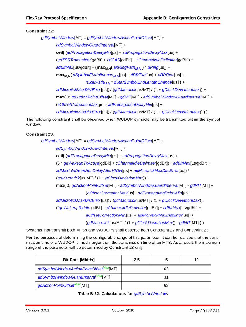
FlexRay Protocol Specification Appendix B: Configuration Constraints
Constraint 22: gdSymbolWindow[MT] = gdSymbolWindowActionPointOffset[MT] +
adSymbolWindowGuardInterval[MT] +
ceil( (adPropagationDelayMin[µs] + adPropagationDelayMax[µs] +
(gdTSSTransmitter[gdBit] + cdCAS[gdBit] + cChannelIdleDelimiter[gdBit]) *
adBitMax[µs/gdBit] + (maxM,N( anRingPathM,N ) * dRing[µs]) +
maxM,N( dSymbolEMIInfluenceM,N[µs] + dBDTxai[µs] + dBDRxai[µs] +
nStarPathM,N * dStarSymbolEndLengthChange[µs] ) +
adMicrotickMaxDistError[µs]) / (gdMacrotick[µs/MT] / (1 + gClockDeviationMax)) +
max( 0; gdActionPointOffset[MT] - gdNIT[MT] - adSymbolWindowGuardInterval[MT] +
(aOffsetCorrectionMax[µs] - adPropagationDelayMin[µs] +
adMicrotickMaxDistError[µs]) / (gdMacrotick[µs/MT] / (1 + gClockDeviationMax)) ) )
The following constraint shall be observed when WUDOP symbols may be transmitted within the symbolwindow.
Constraint 23: gdSymbolWindow[MT] = gdSymbolWindowActionPointOffset[MT] +
adSymbolWindowGuardInterval[MT] +
ceil( (adPropagationDelayMin[µs] + adPropagationDelayMax[µs] +
(5 * gdWakeupTxActive[gdBit] + cChannelIdleDelimiter[gdBit]) * adBitMax[µs/gdBit] +
adMaxIdleDetectionDelayAfterHIGH[µs] + adMicrotickMaxDistError[µs]) /
(gdMacrotick[µs/MT] / (1 + gClockDeviationMax)) +
max( 0; gdActionPointOffset[MT] - adSymbolWindowGuardInterval[MT] - gdNIT[MT] +
(aOffsetCorrectionMax[µs] - adPropagationDelayMin[µs] +
adMicrotickMaxDistError[µs]) / (gdMacrotick[µs/MT] / (1 + gClockDeviationMax));
((gdWakeupRxIdle[gdBit] - cChannelIdleDelimiter[gdBit]) * adBitMax[µs/gdBit] +
aOffsetCorrectionMax[µs] + adMicrotickMaxDistError[µs]) /
(gdMacrotick[µs/MT] / (1 + gClockDeviationMax)) - gdNIT[MT] ) )
Systems that transmit both MTSs and WUDOPs shall observe both Constraint 22 and Constraint 23.
For the purposes of determining the configurable range of this parameter, it can be realized that the trans-mission time of a WUDOP is much larger than the transmission time of an MTS. As a result, the maximumrange of the parameter will be determined by Constraint 23 only.
Bit Rate [Mbit/s] 2.5 5 10
gdSymbolWindowActionPointOffsetMax[MT] 63
adSymbolWindowGuardIntervalMax[MT] 31
gdActionPointOffsetMax[MT] 63
Table B-22: Calculations for gdSymbolWindow.
Version 3.0.1 October 2010 Page 301 of 341

FlexRay Protocol Specification Appendix B: Configuration Constraints
As a result, the parameter gdSymbolWindow must be configurable over a range of 0 to 162 MT.
In addition to the previous constraints, it is possible that for certain system configurations the parametergdSymbolWindow has an additional constraint related to the parameter gdIgnoreAfterTx. Refer to sectionB.4.37 for additional details.
Note - [EPL10] allows the possibility of using an active star device to play the role of a BD in a FlexRaysystem (i.e., from the physical layer perspective the transmission can originate and / or terminate in theactive star). For reasons of clarity, the constraints in this section do not comprehend this (i.e., the constraintsassume the transmission originates or terminates in a bus driver). For systems that utilize the active starsas transceivers it is necessary to modify the constraints to make appropriate use of active star-relatedparameters instead of BD-related parameters (for example, to use dStarRxai instead of dBDRxai).
B.4.14 gMacroPerCycleThe number of macroticks per cycle is based on the cycle duration and the macrotick length.
Constraint 24: gdMacrotick[µs] = gdCycle[µs] / gMacroPerCycle
with gdCycle[µs] <= cdCycleMax[µs] and gdMacrotick[µs] >= cdMinMTNom[µs]. Note that gMacroPer-Cycle[MT] must be an integer value.
gdWakeupTxActive[gdBit] 15 30 60
gdWakeupRxIdle[gdBit] 59
gdNITMin[MT] 2
aOffsetCorrectionMaxa[µs] 0.9955 0.49775 0.49775
adBitMax[µs] 0.4006 0.2003 0.10015
adMaxIdleDetectionDelayAfterHIGHMax[µs] 2.0756 1.8753 1.77515
adPropagationDelayMinMax[µs] 2.999 2.750 2.625
adPropagationDelayMaxMax[µs] 3.051 2.775 2.638
gdMacrotickMin[µs] 2 1
gdSymbolWindowMin[MT] 0b
gdSymbolWindowMax[MT] 145 162 161
a. It is the maximum possible value if gdNIT is a minimum.b. If no symbol window is used at all gdSymbolWindow would be configured to 0 MT.
Bit Rate [Mbit/s] 2.5 5 10
gdCycleMax[µs] = cdCycleMax 16000
gdMacrotickMin[µs] 2 1
gMacroPerCycleMax[MT] 8000 16000 16000
Table B-23: Calculations for gMacroPerCycle.
Bit Rate [Mbit/s] 2.5 5 10
Table B-22: Calculations for gdSymbolWindow.
Version 3.0.1 October 2010 Page 302 of 341

FlexRay Protocol Specification Appendix B: Configuration Constraints
The cycle length in macroticks must also be equivalent to the sum of the lengths of the segments that makeup the cycle.
Constraint 25: gMacroPerCycle[MT] = gdStaticSlot[MT] * gNumberOfStaticSlots + adActionPointDifference[MT] +
gdMinislot[MT] * gNumberOfMinislots + gdSymbolWindow[MT] + gdNIT[MT]
adActionPointDifference[MT] is introduced in B.4.17 and calculated in equation [25].
As a result, the parameter gMacroPerCycle must be configurable over a range of 8 to 16000 MT.
B.4.15 pMicroPerCycleThe cycle length in microticks is calculated using the following equations:
Constraint 26: pMicroPerCycle[µT] = round( gdCycle[µs] / pdMicrotick[µs/µT] )
pMicroPerCycle is always a positive integer number.
In order to define a minimum parameter range that an implementation must support, the minimum numberof microticks in a cycle is determined under the following assumptions:
• the minimum cycle consists of two static slots plus the NIT,• the minimum static slot can be calculated using Constraint 21,• the maximum microtick length is used.
With these assumptions a lower bound can be calculated by using following equations:
[23] pMicroPerCycleMin[µT]= round( (2 * gdStaticSlot[MT] + gdNIT[MT]) *
(gdMacrotick[µs/MT] / pdMicrotick[µs/µT]) )
with gdStaticSlot[MT] equal to Constraint 21:
Bit Rate [Mbit/s] 2.5 5 10
gdStaticSlotMin[MT] 8 5 3
gNumberOfStaticSlotsMin 2
adActionPointDifferenceMin[MT] 0
gdMinislotMin[MT] 2
gNumberOfMinislotsMin[Minislot] 0
gdSymbolWindowMin[MT] 0
gdNITMin[MT] 2
gMacroPerCycleMin[MT] 18 12 8
Table B-24: Calculations for gMacroPerCycle.
Version 3.0.1 October 2010 Page 303 of 341
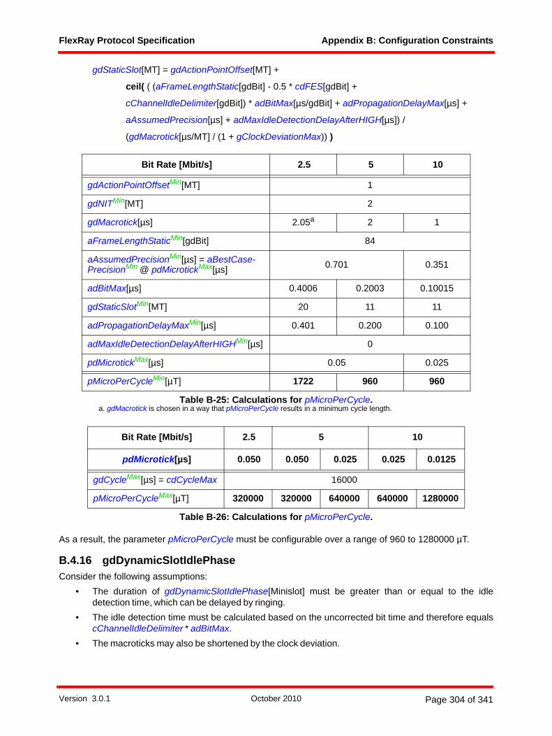
FlexRay Protocol Specification Appendix B: Configuration Constraints
gdStaticSlot[MT] = gdActionPointOffset[MT] +
ceil( ( (aFrameLengthStatic[gdBit] - 0.5 * cdFES[gdBit] +
cChannelIdleDelimiter[gdBit]) * adBitMax[µs/gdBit] + adPropagationDelayMax[µs] +
aAssumedPrecision[µs] + adMaxIdleDetectionDelayAfterHIGH[µs]) /
(gdMacrotick[µs/MT] / (1 + gClockDeviationMax)) )
As a result, the parameter pMicroPerCycle must be configurable over a range of 960 to 1280000 µT.
B.4.16 gdDynamicSlotIdlePhaseConsider the following assumptions:
• The duration of gdDynamicSlotIdlePhase[Minislot] must be greater than or equal to the idledetection time, which can be delayed by ringing.
• The idle detection time must be calculated based on the uncorrected bit time and therefore equalscChannelIdleDelimiter * adBitMax.
• The macroticks may also be shortened by the clock deviation.
Bit Rate [Mbit/s] 2.5 5 10
gdActionPointOffsetMin[MT] 1
gdNITMin[MT] 2
gdMacrotick[µs] 2.05a
a. gdMacrotick is chosen in a way that pMicroPerCycle results in a minimum cycle length.
2 1
aFrameLengthStaticMin[gdBit] 84
aAssumedPrecisionMin[µs] = aBestCase-PrecisionMin @ pdMicrotickMax[µs] 0.701 0.351
adBitMax[µs] 0.4006 0.2003 0.10015
gdStaticSlotMin[MT] 20 11 11
adPropagationDelayMaxMin[µs] 0.401 0.200 0.100
adMaxIdleDetectionDelayAfterHIGHMin[µs] 0
pdMicrotickMax[µs] 0.05 0.025
pMicroPerCycleMin[µT] 1722 960 960
Table B-25: Calculations for pMicroPerCycle.
Bit Rate [Mbit/s] 2.5 5 10
pdMicrotick[µs] 0.050 0.050 0.025 0.025 0.0125
gdCycleMax[µs] = cdCycleMax 16000
pMicroPerCycleMax[µT] 320000 320000 640000 640000 1280000
Table B-26: Calculations for pMicroPerCycle.
Version 3.0.1 October 2010 Page 304 of 341

FlexRay Protocol Specification Appendix B: Configuration Constraints
Constraint 27: gdDynamicSlotIdlePhase[Minislot] >= ceil( ( ceil( (cChannelIdleDelimiter * adBitMax[µs] +
adMaxIdleDetectionDelayAfterHIGH[µs] + aAssumedPrecision[µs] +
adPropagationDelayMax[µs]) /
(gdMacrotick[µs/MT] / (1 + gClockDeviationMax)) ) - (gdMinislot[MT] -
gdMinislotActionPointOffset[MT]) ) / gdMinislot[MT/Minislot] )
The minimum value for gdDynamicSlotIdlePhase would occur for large values of gdMinislot combined withsmall values of gdMinislotActionPointOffset. In these cases Constraint 27 will evaluate to zero.
The maximum required value for gdDynamicSlotIdlePhase cannot easily be determined from Constraint 27by simply using the maximum or minimum values of the input parameters. The worst case situation wouldarise when some nodes in the system detect the last potential idle start event just before the end of its localminislot. In this case, gdDynamicSlotIdlePhase would need to be large enough to ensure that the CHIRP isdetected during the dynamic slot idle phase, and thus
[24] gdDynamicSlotIdlePhaseMax[Minislot] = ceil( (cChannelIdleDelimiter * adBitMax[µs] +
adMicrotickMaxDistError[µs]) /
(gdMacrotick[µs/MT] * (gdMinislot[MT/Minislot] / (1 + gClockDeviationMax))) )
As a result, the parameter gdDynamicSlotIdlePhase must be configurable over a range of 0 to 2 minislots.
B.4.17 gNumberOfMinislotsConsider the following:
[25] adActionPointDifference[MT] = if( or( gdActionPointOffset <= gdMinislotActionPointOffset;
gNumberOfMinislots = 0); 0; gdActionPointOffset - gdMinislotActionPointOffset )
Constraint 28: gNumberOfMinislots[Minislot] = (gMacroPerCycle[MT] - gdNIT[MT] - adActionPointDifference[MT] -
gNumberOfStaticSlots * gdStaticSlot[MT] - gdSymbolWindow[MT]) /
gdMinislot[MT/Minislot]
Bit Rate [Mbit/s] 2.5 5 10
adMicrotickMax[µs] 0.050 0.050 0.025 0.025 0.0125
adBitMax[µs] 0.4006 0.2003 0.10015
gdMacrotickMin[µs] 2 2 1 1 1
gdMinislotMin[MT] 2 2 2 2 2
gdDynamicSlotIdlePhaseMin[Minislot] 0 0 0 0 0
gdDynamicSlotIdlePhaseMax[Minislot] 2 1 2 1 1
Table B-27: Calculations for gdDynamicSlotIdlePhase.
Version 3.0.1 October 2010 Page 305 of 341
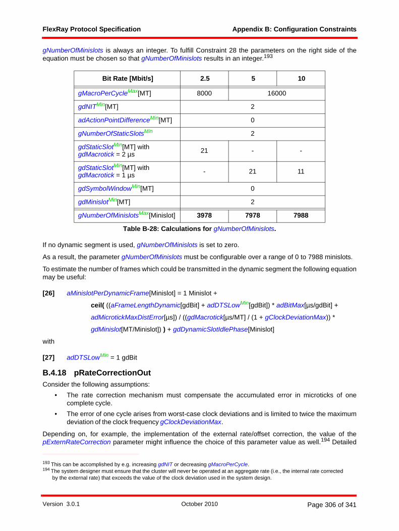
FlexRay Protocol Specification Appendix B: Configuration Constraints
gNumberOfMinislots is always an integer. To fulfill Constraint 28 the parameters on the right side of theequation must be chosen so that gNumberOfMinislots results in an integer.193
If no dynamic segment is used, gNumberOfMinislots is set to zero.
As a result, the parameter gNumberOfMinislots must be configurable over a range of 0 to 7988 minislots.
To estimate the number of frames which could be transmitted in the dynamic segment the following equationmay be useful:
[26] aMinislotPerDynamicFrame[Minislot] = 1 Minislot +
ceil( ((aFrameLengthDynamic[gdBit] + adDTSLowMin[gdBit]) * adBitMax[µs/gdBit] +
adMicrotickMaxDistError[µs]) / ((gdMacrotick[µs/MT] / (1 + gClockDeviationMax)) *
gdMinislot[MT/Minislot]) ) + gdDynamicSlotIdlePhase[Minislot]
with
[27] adDTSLowMin = 1 gdBit
B.4.18 pRateCorrectionOutConsider the following assumptions:
• The rate correction mechanism must compensate the accumulated error in microticks of onecomplete cycle.
• The error of one cycle arises from worst-case clock deviations and is limited to twice the maximumdeviation of the clock frequency gClockDeviationMax.
Depending on, for example, the implementation of the external rate/offset correction, the value of thepExternRateCorrection parameter might influence the choice of this parameter value as well.194 Detailed
Bit Rate [Mbit/s] 2.5 5 10
gMacroPerCycleMax[MT] 8000 16000
gdNITMin[MT] 2
adActionPointDifferenceMin[MT] 0
gNumberOfStaticSlotsMin 2
gdStaticSlotMin[MT] with gdMacrotick = 2 µs 21 - -
gdStaticSlotMin[MT] with gdMacrotick = 1 µs - 21 11
gdSymbolWindowMin[MT] 0
gdMinislotMin[MT] 2
gNumberOfMinislotsMax[Minislot] 3978 7978 7988
Table B-28: Calculations for gNumberOfMinislots.
193 This can be accomplished by e.g. increasing gdNIT or decreasing gMacroPerCycle.194 The system designer must ensure that the cluster will never be operated at an aggregate rate (i.e., the internal rate corrected
by the external rate) that exceeds the value of the clock deviation used in the system design.
Version 3.0.1 October 2010 Page 306 of 341
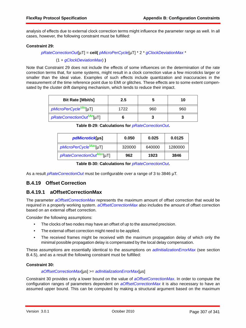
FlexRay Protocol Specification Appendix B: Configuration Constraints
analysis of effects due to external clock correction terms might influence the parameter range as well. In allcases, however, the following constraint must be fulfilled:
Constraint 29: pRateCorrectionOut[µT] = ceil( pMicroPerCycle[µT] * 2 * gClockDeviationMax *
(1 + gClockDeviationMax) )
Note that Constraint 29 does not include the effects of some influences on the determination of the ratecorrection terms that, for some systems, might result in a clock correction value a few microticks larger orsmaller than the ideal value. Examples of such effects include quantization and inaccuracies in themeasurement of the time reference point due to EMI or glitches. These effects are to some extent compen-sated by the cluster drift damping mechanism, which tends to reduce their impact.
As a result pRateCorrectionOut must be configurable over a range of 3 to 3846 µT.
B.4.19 Offset Correction
B.4.19.1 aOffsetCorrectionMaxThe parameter aOffsetCorrectionMax represents the maximum amount of offset correction that would berequired in a properly working system. aOffsetCorrectionMax also includes the amount of offset correctionbased on an external offset correction.
Consider the following assumptions:• The clocks of two nodes may have an offset of up to the assumed precision.• The external offset correction might need to be applied.• The received frames might be received with the maximum propagation delay of which only the
minimal possible propagation delay is compensated by the local delay compensation.
These assumptions are essentially identical to the assumptions on adInitializationErrorMax (see sectionB.4.5), and as a result the following constraint must be fulfilled:
Constraint 30: aOffsetCorrectionMax[µs] >= adInitializationErrorMax[µs]
Constraint 30 provides only a lower bound on the value of aOffsetCorrectionMax. In order to compute theconfiguration ranges of parameters dependent on aOffsetCorrectionMax it is also necessary to have anassumed upper bound. This can be computed by making a structural argument based on the maximum
Bit Rate [Mbit/s] 2.5 5 10
pMicroPerCycleMin[µT] 1722 960 960
pRateCorrectionOutMin[µT] 6 3 3
Table B-29: Calculations for pRateCorrectionOut.
pdMicrotick[µs] 0.050 0.025 0.0125
pMicroPerCycleMax[µT] 320000 640000 1280000
pRateCorrectionOutMax[µT] 962 1923 3846
Table B-30: Calculations for pRateCorrectionOut.
Version 3.0.1 October 2010 Page 307 of 341

FlexRay Protocol Specification Appendix B: Configuration Constraints
measured offset values possible given the parameters that determine the characteristics of the static slot(i.e., gdStaticSlot and gdActionPointOffset).
As the offset correction term can be either negative or positive, it is necessary to distinguish between themaximum negative and maximum positive value from which the maximum absolute value is taken.Therefore two auxiliary variables are introduced: aNegativeOffsetCorrectionMax and aPositiveOffsetCor-rectionMax. To determine the maximum offset correction value only the absolute value of the negative offsetcorrection is considered, which is reflected in the equation below. Therefore the equation for aNegativeOff-setCorrectionMax is formulated such that is results in a positive value.
Consider the following assumptions for deriving the maximum possible negative offset correction:• The secondary time reference point of the incoming frame is synchronous with the slot boundary.195
• The maximum possible delay compensation and decoding correction is applied.• The maximum possible external offset correction is considered.
[28] aNegativeOffsetCorrectionMax[µs] = gdActionPointOffset[MT] * (gdMacrotick[µs/MT] /
(1 - gClockDeviationMax)) + maxN( adMicrotickDistErrorN[µs] +
( max( pDelayCompensation[A]N[µT] ; pDelayCompensation[B]N[µT] ) +
pDecodingCorrectionN[µT]) * (pdMicrotickN[µs/µT] / (1 - gClockDeviationMax)) ) +
gExternOffsetCorrection[µs]
Consider the following assumptions for deriving the maximum possible positive offset correction:• The frame decoded signal of the incoming sync frame arrives synchronous with the slot
boundary.196
• There are exactly 80 plus 20 times gPayloadLengthStatic bits between the secondary timereference point and the frame decoded signal.
• The received frame is transmitted with the minimum allowed bit length.• The received frame is subjected to minimum delay compensation and decoding correction.
[29] aPositiveOffsetCorrectionMax[µs] = (gdStaticSlot[MT] - gdActionPointOffset[MT]) *
(gdMacrotick[µs/MT] / (1 - gClockDeviationMax)) -
(8 + 2 * gPayloadLengthStatic) * 10[gdBit] * adBitMin[µs/gdBit] -
minN( -adMicrotickDistErrorN[µs] + ( min( pDelayCompensation[A]N[µT] ;
pDelayCompensation[B]N[µT] ) + pDecodingCorrectionN[µT]) *
(pdMicrotickN[µs/µT] / (1 + gClockDeviationMax)) ) + gExternOffsetCorrection[µs]
Using these auxiliary variables, it is possible to derive a maximal absolute value for offset correction:
[30] aOffsetCorrectionMax[µs] <= max( aNegativeOffsetCorrectionMax[µs] ;
aPositiveOffsetCorrectionMax[µs] )
195 This is actually impossible as such a frame would be discarded by the FSP.196 This causes a boundary violation, but the frame is still used for clock synchronization.
Version 3.0.1 October 2010 Page 308 of 341

FlexRay Protocol Specification Appendix B: Configuration Constraints
B.4.19.2 pOffsetCorrectionOutSince the check for the offset correction is applied before the external offset correction is included, theeffects of the external offset correction that are included in the definition of aOffsetCorrectionMax must beremoved when calculating pOffsetCorrectionOut.
Constraint 31: pOffsetCorrectionOut[µT] = ceil( (aOffsetCorrectionMax[µs] - gExternOffsetCorrection[µs]) /
(pdMicrotick[µs/µT] / (1 + gClockDeviationMax)) )
Bit Rate [Mbit/s] 2.5 5 10
adMicrotickMax[µs] 0.050 0.050 0.025 0.025 0.0125
adInitializationErrorMaxMin[µs] 0.701 0.701 0.351 0.351 0.175
aOffsetCorrectionMaxMin[µs] 0.701 0.701 0.351 0.351 0.175
gdMacrotickMax[µs] 6 6 6 6 3
gdActionPointOffsetMax[MT] 63
gdStaticSlotMax[MT]a
a. This value was derived just as in Table B-21, but with a value of 6, respectively 3, for gdMacrotick.
304 216 172 217
gPayloadLengthStaticMax[two-byte word]b
b. The largest frame size is assumed as this results in the largest possible discrepancy between nominal andactual frame length.
127c
c. For 2.5 Mbit/s the calculations in this table are conservative, as payload length is restricted by the maximum trans-mission duration adTxMax. See section B.4.40 for details.
adBitMin[µs] 0.3994 0.1997 0.09985
pDelayCompensation[Ch]Min[µT] 7 4 7 4 7
pDelayCompensation[Ch]Max[µT] 61 55 111 105 211
pDecodingCorrectionMin[µT] 24 12 24 12 24
pDecodingCorrectionMax[µT] 56 40 80 68 136
pdMicrotick[µs] 0.050 0.050 0.025 0.025 0.0125
gExternOffsetCorrectionMax[µs] 0.35
aNegativeOffsetCorrectionMaxMax[µs] 384.827 383.725 383.725 383.274 193.990
aPositiveOffsetCorrectionMaxMax[µs] 400.597 395.766 395.766 393.351 201.063
aOffsetCorrectionMaxMax[µs] 400.597 395.766 395.766 393.351 201.063
Table B-31: Calculations for aOffsetCorrectionMax.
Version 3.0.1 October 2010 Page 309 of 341

FlexRay Protocol Specification Appendix B: Configuration Constraints
As a result, the parameter pOffsetCorrectionOut shall be configurable over a range of 15 to 16082 µT.
B.4.20 pOffsetCorrectionStartConsider the following assumptions:
• The offset correction phase starts at pOffsetCorrectionStart.• The offset correction phase ends at the end of the cycle.
Thus it holds that
Constraint 32: pOffsetCorrectionStart[MT] = gMacroPerCycle[MT] - adOffsetCorrection[MT]
with adOffsetCorrection the length of the offset correction phase, which is constrained in equation [33] inthe next section. This parameter should be set to the same value for all nodes in a cluster.197
B.4.21 gdNITConsider the following assumptions:
1. The NIT consists of offset calculation phase and offset correction phase. 2. The duration of offset calculation may vary from implementation to implementation, and may vary
depending on the number of received sync frames. The offset calculation must be completed before the start of the offset correction phase. The upper limit for the duration of the offset calculation is defined in section 8.6.2. The offset correction calculation must be completed no later than cdMaxOff-setCalculation after the end of the static segment or 1 MT after the start of the NIT, whichever occurs later.
3. The earliest start of the offset correction phase is 1 MT after the start of the NIT.4. The duration of offset correction phase is at least 1 MT.5. The maximum possible value for offset correction is aOffsetCorrectionMax. The offset correction
phase must be long enough (i.e., contain enough macroticks) to correct this amount of offset while still keeping the length of shortened macroticks greater than or equal to cMicroPerMacroMin microticks.
Bit Rate [Mbit/s] 2.5 5 10
pdMicrotick[µs] 0.050 0.050 0.025 0.025 0.0125
aOffsetCorrectionMaxMin[µs] 0.701 0.701 0.351 0.351 0.175
aOffsetCorrectionMaxMax[µs] 400.597 395.766 395.766 393.351 193.990
gExternOffsetCorrectionMin[µs] 0
gExternOffsetCorrectionMax[µs] 0.35
pOffsetCorrectionOutMin[µT] 15 15 15 15 15
pOffsetCorrectionOutMax[µT] 8017 7921 15841 15744 16082
Table B-32: Calculations for pOffsetCorrectionOut.
197 For TT-E systems it may be beneficial to allow different offset correction starts for the coldstart and non-sync nodes (see section B.7.9), and as a result this is a p-parameter rather than a g-parameter.
Version 3.0.1 October 2010 Page 310 of 341

FlexRay Protocol Specification Appendix B: Configuration Constraints
6. The offset correction phase and the offset calculation phase can be overlaid with parts of the rate cal-culation phase.
7. The duration of rate calculation may vary from implementation to implementation, and may vary depending on the number of received sync frames. The rate calculation must be completed before the end of the NIT. The upper limit for the duration of the rate calculation is defined in section 8.6.3. The rate correction calculation must be completed no later than cdMaxRateCalculation after the end of the static segment or 2 MT after the start of the NIT, whichever occurs later. This can induce the need for a prolonged NIT.
Due to item 1, 6 and 7, the NIT length gdNIT is either the remaining time required to calculate the offsetcorrection and then execute it, or the remaining time required to ensure that rate calculation finishes beforethe cycle ends, whichever takes longer. Thus gdNIT can be constrained by
Constraint 33: gdNIT[MT] >= max( adRemRateCalculation[MT]; adRemOffsetCalculation[MT] +
adOffsetCorrection [MT] )
Due to item 2 the remaining length of the offset calculation phase during the NIT adRemOffsetCalculationcan be defined by
[31] adRemOffsetCalculation[MT] <= max( 1; ceil( (cdMaxOffsetCalculation[µT] *
adMicrotickMax[µs/µT] / (1 - gClockDeviationMax) + adMicrotickMaxDistError[µs] -
(adActionPointDifference[MT] +
gdMinislot[MT] * gNumberOfMinislots + gdSymbolWindow[MT]) * (gdMacrotick[µs] /
(1 + gClockDeviationMax)) ) / (gdMacrotick[µs] / (1 + gClockDeviationMax)) ) )
[32] adRemOffsetCalculation[MT] >= 1
With item 5 adOffsetCorrection, the length of the offset correction phase, can be constrained by
[33] adOffsetCorrection[MT] >= ceil( (aOffsetCorrectionMax[µs] + adMicrotickMaxDistError[µs]) /
(gdMacrotick[µs/MT] / (1 + gClockDeviationMax) - adMicrotickMax[µs/µT] *
cMicroPerMacroMin[µT/MT] / (1 - gClockDeviationMax)) )
Finally assumption 7 helps to define adRemRateCalculation, the time required to complete the remainingrate calculation after the beginning of the NIT. The rate calculation has to be ready early enough that it willfinish before the cycle start even if a maximum negative offset correction of aOffsetCorrectionMax isapplied, effectively adding aOffsetCorrectionMax to the required calculation time. It is therefore constrainedby
[34] adRemRateCalculation[MT] <= max( 1; ceil( (cdMaxRateCalculation[µT] * adMicrotickMax[µs/µT] /
(1 - gClockDeviationMax) + adMicrotickMaxDistError[µs] -
(adActionPointDifference[MT] + gdMinislot[MT] *
gNumberOfMinislots + gdSymbolWindow[MT]) * gdMacrotick[µs] /
(1 + gClockDeviationMax) + aOffsetCorrectionMax[µs] ) /
(gdMacrotick[µs] / (1 + gClockDeviationMax)) ) )
Version 3.0.1 October 2010 Page 311 of 341

FlexRay Protocol Specification Appendix B: Configuration Constraints
Normally there is a period of inactivity following the end of transmission in a static slot and the start of thenext static slot. If the cycle contains a dynamic segment, however, the period following the end of trans-mission of the dynamic segment and the beginning of the first static slot consists only of the period after thedynamic transmission ends until the end of the dynamic segment, the duration of a symbol window (if any),and the duration of the NIT (which can be shortened by a negative offset correction). If it is desired that allstatic slots should have a certain minimum margin between the end of the previous transmission and thebeginning of the static slot it may be necessary to use a larger network idle time than would normally berequired. For example, if Constraint 20 (which assumes the "space" at the end of a static slot is approxi-mately equal to gdActionPointOffset) is used, the following equation would ensure that there is sufficientspace between the end of a dynamic transmission and the beginning of the first static slot:
[35] gdNIT[MT] >= gdActionPointOffset[MT] - gdSymbolWindow[MT] - (gdMinislot[MT] -
gdMinislotActionPointOffset[MT] +
gdDynamicSlotIdlePhase[Minislot] * gdMinislot[MT/Minislot]) +
ceil( (aOffsetCorrectionMax[µs] + adMicrotickMaxDistError[µs]) /
(gdMacrotick[µs/MT] / (1 + gClockDeviationMax)) )
This equation would only apply for cycles that actually contain a dynamic segment. Obviously, if a differentamount of "space" is reserved at the end of a static slot (for example, if gdStaticSlot is set using Constraint21 instead of Constraint 20, or even a larger margin than implied by Constraint 20) equation [35] could bemodified to provide a larger or smaller margin.198 If the cycle does not contain a dynamic segment there isno need for an additional equation limiting the minimum size of the NIT.
The configurable minimum for gdNIT can be found by making the assumption that the NIT consists of only1 MT for offset calculation and only 1 MT for offset correction. The configurable maximum for gdNIT can befound by making the assumption that the cycle consist of the largest possible number of macroticks and theNIT is the duration of the cycle minus the duration of two of the shortest static slots possible using thesmallest possible nominal macrotick duration.
As a result, the parameter gdNIT must be configurable over a range of 2 MT to 15978 MT.
B.4.22 pExternRateCorrectionConsider the following assumption:
• The absolute value of the external rate correction value shouldn't be greater than the maximumacceptable rate correction value pRateCorrectionOut.
Constraint 34: pExternRateCorrection[µT] <= pRateCorrectionOut[µT]
The application of external rate or offset correction is controlled by the hosts, and should be synchronizedsuch that all nodes apply the same value at the same time in the same direction. In order to achieve thissynchronization between the hosts is necessary.
gExternRateCorrectionMax[µs] is the maximum external rate correction value applied in a cluster. gExtern-RateCorrection has to be chosen in a way that for every microtick duration used in the cluster the resultingpExternRateCorrection values are integer numbers.199
198 If the symbol window is used for transmission of MTS's or WUDOP's Constraints 22 and 23 will ensure the same property and an equation similar to equation [35] is not necessary.
199 The ability to actually apply an external rate correction is affected by the cluster drift damping. The cluster drift damping could even be set to zero for systems where an external rate correction serves to prevent large deviations of the operating rate of the cluster.
Version 3.0.1 October 2010 Page 312 of 341

FlexRay Protocol Specification Appendix B: Configuration Constraints
Constraint 35: pExternRateCorrection[µT] = gExternRateCorrection[µs] / pdMicrotick[µs/µT]
The range of pExternRateCorrection shall be configurable over a range of 0 to 28 µT.200
B.4.23 pExternOffsetCorrectionConsider the following assumption:
• The absolute value of the external offset correction value shouldn't be greater than the maximumacceptable offset correction value pOffsetCorrectionOut.
gExternOffsetCorrectionMax[µs] is the maximum external offset correction value applied in a cluster.gExternOffsetCorrection has to be chosen in a way that for every microtick duration used in the cluster theresulting pExternOffsetCorrection values are integers.
Constraint 36: pExternOffsetCorrection[µT] = gExternOffsetCorrection[µs] / pdMicrotick[µs/µT]
The range of pExternOffsetCorrection shall be configurable over a range of 0 to 28 µT.201
Bit Rate [Mbit/s] 2.5 5 10
adMicrotickMax[µs] 0.050 0.050 0.025 0.025 0.0125
gExternRateCorrectionMin[µs] 0
gExternRateCorrectionMax[µs] 0.35
pdMicrotickMin[µs] 0.050 0.025 0.025 0.0125 0.0125
pExternRateCorrectionMin[µT] 0
pExternRateCorrectionMax[µT] 7 14 14 28 28
Table B-33: Calculations for pExternRateCorrection.
200 A small value for pExternRateCorrection (much smaller than pRateCorrectionOut) has the advantage that a node which does not apply the external rate correction due to a fault stays synchronized with the other nodes in the cluster.
Bit Rate [Mbit/s] 2.5 5 10
adMicrotickMax[µs] 0.050 0.050 0.025 0.025 0.0125
gExternOffsetCorrectionMin[µs] 0
gExternOffsetCorrectionMax[µs] 0.35
pdMicrotickMin[µs] 0.050 0.025 0.025 0.0125 0.0125
pExternOffsetCorrectionMin[µT] 0
pExternOffsetCorrectionMax[µT] 7 14 14 28 28
Table B-34: Calculations for pExternOffsetCorrection.
201 A small value for pExternOffsetCorrection (much smaller than pOffsetCorrectionOut) has the advantage that a node which does not apply the external offset correction due to a fault stays synchronized with the other nodes in the cluster.
Version 3.0.1 October 2010 Page 313 of 341

FlexRay Protocol Specification Appendix B: Configuration Constraints
B.4.24 pdListenTimeoutTo configure the parameter pdListenTimeout the following constraint must be taken into account:
Constraint 37: pdListenTimeout[µT] = 2 * (pMicroPerCycle[µT] + pRateCorrectionOut[µT])
As a result, the parameter pdListenTimeout shall be configurable over a range of 1926 to 2567692 µT.
B.4.25 pDecodingCorrectionConsider following assumption:
• The time difference between the secondary time reference point and the primary time referencepoint is the summation of pDecodingCorrection and pDelayCompensation (see Figure 3-11).
Constraint 38: pDecodingCorrection[µT] = round( ((gdTSSTransmitter[gdBit] + cdFSS[gdBit] + 0.5 *
cdBSS[gdBit]) * cSamplesPerBit[samples/gdBit]) / pSamplesPerMicrotick[samples/µT] )
As a result, the parameter pDecodingCorrection shall be configurable between 12 and 136 µT.
pdMicrotick[µs] 0.050 0.025 0.0125
pMicroPerCycleMax[µT] 320000 640000 1280000
pRateCorrectionOutMax[µT] 962 1923 3846
pdListenTimeoutMax[µT] 641924 1283846 2567692
Table B-35: Calculations for pdListenTimeout.
Bit Rate [Mbit/s] 2.5 5 10
pMicroPerCycleMin[µT] 1722 960 960
pRateCorrectionOutMin[µT] 6 3 3
pdListenTimeoutMin[µT] 3456 1926 1926
Table B-36: Calculations for pdListenTimeout.
Bit Rate [Mbit/s] 2.5 5 10
pdMicrotick[µs] 0.050 0.050 0.025 0.025 0.0125
gdTSSTransmitterMin[gdBit] 1
gdTSSTransmitterMax[gdBit] 5 8 15
pSamplesPerMicrotick 1 2 1 2 1
pDecodingCorrectionMin[µT] 24 12 24 12 24
pDecodingCorrectionMax[µT] 56 40 80 68 136
Table B-37: Calculations for pDecodingCorrection.
Version 3.0.1 October 2010 Page 314 of 341

FlexRay Protocol Specification Appendix B: Configuration Constraints
B.4.26 pDelayCompensationConsider the following assumption:
• For the minimum propagation delay the general internal delay needs to be replaced by the specificone of the device in question.
Therefore the following constraints must be taken into account:
Constraint 39: pDelayCompensation[Ch][µT] >= ceil( (adPropagationDelayMin[Ch][µs] +
(adInternalRxDelay[samples] - minN( adInternalRxDelayN[samples] ) ) *
gdSampleClockPeriod[µs/samples]) / pdMicrotick[µs/µT] )
Constraint 40: pDelayCompensation[Ch][µT] <= floor( adPropagationDelayMax[Ch][µs] / pdMicrotick[µs/µT] )
In the absence of information on the specific distributions of the propagation delays in the cluster, it isrecommended to set this parameter to a value corresponding to the lower value of Constraint 39. In casethat not all communication controllers use the same microtick length, care should be taken that all commu-nication controllers use effectively the same value in real time (for example, by choosing a slightly largervalue that is evenly divisible by all occurring microtick lengths in the cluster).
Using detailed knowledge about the topology of the cluster for the configuration of pDelayCompensation,an improvement in both precision and NIT length is possible; the details are however beyond the scope ofthis specification.202
The values and constraints given in this appendix for precision and NIT assume an identical value in realtime for all nodes of the cluster, i.e., the product of a node's configuration of pDelayCompensation and thenode's microtick duration is the same for all nodes in the cluster.
As a result, the parameter pDelayCompensation[Ch] shall be configurable between 4 and 211 µT.
202 A starting point is given in chapter 7 of [Ung09] - if the exact propagation delays of all relevant sync frames are known it is possible to more accurately correct for the effects of the propagation delays. For example, by configuring the value of pDelayCompensation of a specific node to the smallest propagation delay affecting any sync frame that node receives, the precision formula is improved by replacing the absolute difference of largest and smallest propagation delay by one that maximizes over the local differences. A further optimization would attempt to evenly spread the measured offset term around zero, so the systematic offset drift is reduced and the NIT can be configured more efficiently.
Bit Rate [Mbit/s] 2.5 5 10
pdMicrotick[µs] 0.050 0.050 0.025 0.025 0.0125
adInternalRxDelay[samples] -minN(adInternalRxDelayN[samples]) 0
gdSampleClockPeriod[µs] 0.050 0.025 0.0125
adPropagationDelayMin[Ch]Min[µs] 0.349 0.175 0.087
pDelayCompensation[Ch]Min[µT] 7 4 7 4 7
adPropagationDelayMax[Ch]Max[µs] 3.051 2.775 2.638
pDelayCompensation[Ch]Max[µT] 61 55 111 105 211
Table B-38: Calculations for pDelayCompensation[Ch].
Version 3.0.1 October 2010 Page 315 of 341

FlexRay Protocol Specification Appendix B: Configuration Constraints
B.4.27 pMacroInitialOffsetConsider the following assumption:
• pMacroInitialOffset[Ch] has to be in the range of gdActionPointOffset < pMacroInitialOffset[Ch] < gdStaticSlot.
Constraint 41: pMacroInitialOffset[Ch][MT] = gdActionPointOffset[MT] + ceil( (pDecodingCorrection[µT] +
pDelayCompensation[Ch][µT]) / aMicroPerMacroNom[µT/MT] )
As a result, the parameter pMacroInitialOffset[Ch] shall be configurable between 2 and 68 MT.
B.4.28 pMicroInitialOffsetConsider the following assumptions:
• The CSS process sets up a macrotick timing grid that is aligned to the primary TRP of the receivedframe used to start the macrotick generation process. The primary TRP is never actually deter-mined, but it is assumed to occur before the detected secondary TRP as shown in Figure 3-11.Macrotick generation needs to be started at a point that represents an integral number of nominalmacroticks from the assumed primary TRP. As a result, pMicroInitialOffset[Ch] is the number ofmicroticks between the secondary TRP and the start of the subsequent macrotick on a macrotickgrid aligned with the assumed primary TRP (see Figure B-1).
Bit Rate [Mbit/s] 2.5 5 10
pdMicrotick[µs] 0.050 0.050 0.025 0.025 0.0125
gdActionPointOffsetMin[MT] 1 1 1
gdActionPointOffsetMax[MT] 63 63 63
pDecodingCorrectionMin[µT] 24 12 24 12 24
pDecodingCorrectionMax[µT] 56 40 80 68 136
pDelayCompensation[Ch]Min[µT] 7 4 7 4 7
pDelayCompensation[Ch]Max[µT] 61 55 111 105 211
aMicroPerMacroNomMin[µT] 40 40 40 40 80
aMicroPerMacroNomMax[µT] 120 120 240 240 240
pMacroInitialOffset[Ch]Min[MT] 2 2 2 2 2
pMacroInitialOffset[Ch]Max[MT] 66 66 68 68 68
Table B-39: Calculations for pMacroInitialOffset[Ch].
Version 3.0.1 October 2010 Page 316 of 341

FlexRay Protocol Specification Appendix B: Configuration Constraints
Figure B-1: Illustration of pMicroInitialOffset[Ch].
Constraint 42: pMicroInitialOffset[Ch][µT] = floor( ceil( (pDecodingCorrection[µT] +
pDelayCompensation[Ch][µT]) / aMicroPerMacroNom[µT/MT] ) *
aMicroPerMacroNom[µT/MT] ) -
(pDecodingCorrection[µT] + pDelayCompensation[Ch][µT])
Since aMicroPerMacroNom must be in the range
cMicroPerMacroNomMin <= aMicroPerMacroNom <= cMicroPerMacroNomMax
the results of Constraint 42 will lie in the range from 0 to cMicroPerMacroNomMax - 1. As a result, theparameter pMicroInitialOffset[Ch] shall be configurable over a range of 0 to 239 µT.
Because of the mechanisms defined in the clock synchronization startup process the following constraintmust also be fulfilled:
Constraint 43: 203
pMicroInitialOffset[Ch][µT] < floor( (((5 + 2 * gPayloadLengthStatic + 3) * 10[gdBit] - cdBSS[gdBit]
+ 0.5 * cdFES[gdBit]) * adBitMin[µs/gdBit]) /
(pdMicrotick[µs/µT] / (1 - gClockDeviationMax)) )
B.4.29 pLatestTxpLatestTx defines the last allowed starting point of a frame transmission in the dynamic segment. Thisparameter may be used by the system designer to ensure that if a node begins to transmit a frame in thedynamic segment that it will be allowed to complete the transmission (i.e., if transmission is allowed to start,there is enough time remaining in the dynamic segment to allow the transmission to complete). Obviously,the time required to complete the transmission is dependent on the size of the frame. Substituting thedesired dynamic frame length aPayloadLengthDynamic for aPayloadLength in equation [21] results in
[36] aFrameLengthDynamic = aFrameLength with aPayloadLength = pPayloadLengthDynMax204
203 Constraint 43 is necessary to ensure that events occur in the correct order in the clock synchronization startup process. For systems that follow the constraints in this appendix, this constraint will always be fulfilled and does not conflict with Constraint 42.
pDecodingCorrection
action point
pDelayCompensation[Ch]
secondary TRPprimary TRP
pMicroInitialOffset[Ch]
macroticks
receiver zVotedVal
Version 3.0.1 October 2010 Page 317 of 341

FlexRay Protocol Specification Appendix B: Configuration Constraints
Using this, it is possible to develop an equation for a configuration of pLatestTx that would ensure that, oncestarted, a transmission of a frame with a payload length less than or equal to aPayloadLengthDynamic willbe able to be completed before the end of the dynamic segment.
Consider the following assumptions: • After each frame the dynamic slot idle phase must be taken into account.• The influence of the clock deviation (gClockDeviationMax) on the length of a macrotick must be
taken into account.
With the definition of aFrameLengthDynamic in equation [36] and adDTSLowMin in equation [27], theconstraint on pLatestTx is
Constraint 44: pLatestTx[Minislot] <= floor( gNumberOfMinislots[Minislot] - ( ((aFrameLengthDynamic[gdBit] +
adDTSLowMin[gdBit]) * adBitMax[µs/gdBit] + adMicrotickDistError[µs]) /
((gdMacrotick[µs/MT] / (1 + gClockDeviationMax)) * gdMinislot[MT/Minislot]) ) -
gdDynamicSlotIdlePhase[Minislot] )
Constraint 44 defines, as a function of aPayloadLengthDynamic, the value that must be configured intopLatestTx to ensure that transmissions that begin will be allowed to complete.
A system designer can achieve various node behaviors through the choice of the value for pLatestTx. Somepossibilities include:
• The node is not allowed to transmit in the dynamic segment. This could be achieved by settingpLatestTx to zero.
• The node is only allowed to transmit if all its possible frames could be completely transmitted. Thiscould be achieved by setting pLatestTx to the value given by calculating Constraint 44 with aPayloa-dLengthDynamic set to the payload length of longest possible dynamic frame sent by the node.
• The node is only allowed to transmit if frames of a defined length could be completely transmitted.This length might be shorter than the longest possible frame sent by the node in the dynamicsegment205. This could be achieved by setting pLatestTx to the value given by calculatingConstraint 44 with aPayloadLengthDynamic set to the desired payload length.
• The node is only allowed to begin transmissions in the first portion of the dynamic segment. Thiscould be achieved by setting pLatestTx to a value greater than zero, but still near the beginning ofthe dynamic segment.
• The node is allowed to start a transmission at any time in the dynamic segment even if the framemay not be completely transmitted (i.e., the pLatestTx mechanism is effectively circumvented). Thiscould be achieved by setting pLatestTx to gNumberOfMinislots.
The value of pLatestTx must be configurable over a range of 0 to gNumberOfMinislotsMax (see sectionB.4.17), and thus must be configurable over a range of 0 to 7988 minislots.
B.4.30 gdTSSTransmitterConsider the following assumptions:
204 This parameter may be different for each node. It is the length of the longest possible frame sent in the dynamic segment by the node under consideration.
205 Such a configuration might be useful if, for example, a system designer knows that a node may send long frames, but only at the beginning of the dynamic segment.
Version 3.0.1 October 2010 Page 318 of 341

FlexRay Protocol Specification Appendix B: Configuration Constraints
• The first low phase of a frame (TSS), as seen by the receiver, may be changed at the beginning byan interval of up to dFrameTSSLengthChangeM,N + dFrameTSSEMIInfluenceM,N as the framepasses through the network. The amount of change depends on the particular bus drivers andactive stars that are involved, and on the channel topology layout. The parameter gdTSSTrans-mitter must be chosen to be greater than the expected worst case truncation of a frame.
• Receiving nodes must receive at least one complete bit of the TSS phase.• The nominal bit rates of different nodes in the cluster may differ by the maximum allowable clock
deviation. The transmitted TSS duration must account for the case where the transmitter sends bitsthat are as short as allowed and the receiver expects bits that are as long as allowed.
Constraint 45: 206
gdTSSTransmitter[gdBit] >= ceil( (adBitMax[µs] - minM,N( dFrameTSSLengthChangeM,N[µs] +
dFrameTSSEMIInfluenceM,N[µs] ) ) / adBitMin[µs/gdBit] )
Since every CAS or MTS symbol is prepended by a TSS, the resulting bit stream will be lengthened orshortened by an interval of up to dSymbolLengthChangeM,N + dSymbolEMIInfluenceM,N as the low phasepasses through the network. The amount of length change depends on the active stars that are involvedand on the channel topology layout.
In order to avoid shortening below the acceptance level for symbol reception the following Constraint mustalso be fulfilled:
Constraint 46: gdTSSTransmitter[gdBit] >= ceil( (cdCASRxLowMin[gdBit] * adBitMax[µs/gdBit] -
minM,N( dSymbolLengthChangeM,N[µs] + dSymbolEMIInfluenceM,N[µs] ) ) /
adBitMin[µs/gdBit] - cdCAS[gdBit] )
By definition, the transmitted TSS must always consist of at least one bit. The calculation of the maximumnumber of bits required is shown in Table B-40. As a result, the parameter gdTSSTransmitter shall be config-urable between 1 and 15 gdBit.
206 A description of the dFrameTSSLengthChangeM,N and dFrameTSSEMIInfluenceM,N parameters may be found in [EPL10]. The maximum values of these parameters for systems with 0, 1, and 2 active stars may be found in [EPLAN10]. The configuration constraint is expressed in terms of the actual values of the TSS truncation present in the system under consideration. This may be less than the maximum values expressed in the [EPL10].
Bit Rate [Mbit/s] 2.5 5 10
adBitMax[µs] 0.4006 0.2003 0.10015
adBitMin[µs] 0.3994 0.1997 0.09985
dFrameTSSLengthChangeM,NMin[µs]a
a. for a network with two active stars
-1.3
dFrameTSSEMIInfluenceM,NMin[µs]a -0.075
dSymbolLengthChangeM,NMin[µs]a -0.925
dSymbolEMIInfluenceM,NMin[µs]a -0.3
gdTSSTransmitterMax[gdBit] 5 8 15
Table B-40: Calculations for gdTSSTransmitter.
Version 3.0.1 October 2010 Page 319 of 341
FlexRay Protocol Specification Appendix B: Configuration Constraints
B.4.31 gdCASRxLowMaxConsider the following assumption:
• A CAS symbol shall be accepted even if it overlaps with another CAS symbol
The situations that can cause CAS overlaps during startup are quite complicated, and depend heavily onseveral characteristics of the system in question, including system topology, macrotick duration, propa-gation delays, ringing, symbol length change, etc. Further, the worst case situations themselves are alsocomplicated, as some involve a combination of events that may be considered unlikely by some systemdesigners (for example, the expiration of the startup noise timer sufficiently close to the completion of thereception of a CAS from another node), and vary from system to system. As a result of this complexity,presenting a single configuration constraint for all the possible combinations is beyond the scope of thisspecification.
In order to provide some guidance, the following conservative equations are presented.
Equation [37] gives an upper bound for situations in which there are no CAS collisions (i.e., where only asingle node can act as a leading coldstarter).
[37] gdCASRxLowMax[gdBit] = ceil( ((gdTSSTransmitter[gdBit] + cdCAS[gdBit]) * adBitMax[µs/gdBit] +
maxM,N( dSymbolLengthChangeM,N[µs] + dSymbolEMIInfluenceM,N[µs] +
anRingPathM,N * dRing[µs] ) ) / adBitMin[µs/gdBit] )
Equation [38] gives an upper bound for situations in which there is an overlap of the CAS's of two coldstartnodes, assuming that each CAS experiences the maximum lengthening possible in the system
[38] gdCASRxLowMax[gdBit] = ceil( ( 2 * ( (gdTSSTransmitter[gdBit] + cdCAS[gdBit] ) *
adBitMax[µs/gdBit] + maxM,N( dSymbolLengthChangeM,N[µs] +
dSymbolEMIInfluenceM,N[µs] + anRingPathM,N * dRing[µs] ) ) +
adBitMin[µs] ) / adBitMin[µs/gdBit] )
Normally the minimum value for gdCASRxLowMax is limited by the minimum acceptance value cdCASRx-LowMin which would imply a minimum value of 29 for gdCASRxLowMax. There are certain use cases,however, where the system designer might wish to eliminate the effects caused by a reception of a CASduring the startup procedure. This can be accomplished by configuring the value of gdCASRxLowMax tobe less than cdCASRxLowMin207. In order to allow such configurations, the value of gdCASRxLowMaxmust be able to be configured to be less than cdCASRxLowMin.
In order to determine the maximum configurable value of gdCASRxLowMax a margin beyond the maximumvalue of equation [38] is taken into account. As a result, the parameter gdCASRxLowMax shall be config-urable over a range of 28 to 254 gdBit.
B.4.32 gdWakeupTxIdleThe following constraint must be met:
207 As the same detection is used for both CAS's and MTS's, such a system would also not be able to detect the reception of MTS's.
Version 3.0.1 October 2010 Page 320 of 341
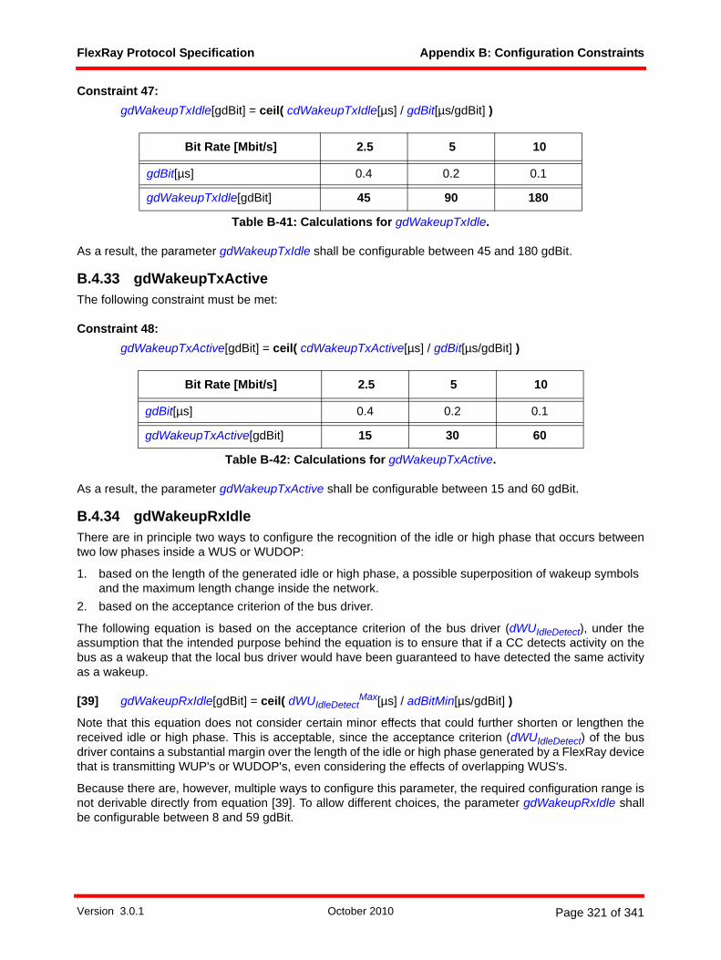
FlexRay Protocol Specification Appendix B: Configuration Constraints
Constraint 47: gdWakeupTxIdle[gdBit] = ceil( cdWakeupTxIdle[µs] / gdBit[µs/gdBit] )
As a result, the parameter gdWakeupTxIdle shall be configurable between 45 and 180 gdBit.
B.4.33 gdWakeupTxActiveThe following constraint must be met:
Constraint 48: gdWakeupTxActive[gdBit] = ceil( cdWakeupTxActive[µs] / gdBit[µs/gdBit] )
As a result, the parameter gdWakeupTxActive shall be configurable between 15 and 60 gdBit.
B.4.34 gdWakeupRxIdleThere are in principle two ways to configure the recognition of the idle or high phase that occurs betweentwo low phases inside a WUS or WUDOP:
1. based on the length of the generated idle or high phase, a possible superposition of wakeup symbols and the maximum length change inside the network.
2. based on the acceptance criterion of the bus driver.
The following equation is based on the acceptance criterion of the bus driver (dWUIdleDetect), under theassumption that the intended purpose behind the equation is to ensure that if a CC detects activity on thebus as a wakeup that the local bus driver would have been guaranteed to have detected the same activityas a wakeup.
[39] gdWakeupRxIdle[gdBit] = ceil( dWUIdleDetectMax[µs] / adBitMin[µs/gdBit] )
Note that this equation does not consider certain minor effects that could further shorten or lengthen thereceived idle or high phase. This is acceptable, since the acceptance criterion (dWUIdleDetect) of the busdriver contains a substantial margin over the length of the idle or high phase generated by a FlexRay devicethat is transmitting WUP's or WUDOP's, even considering the effects of overlapping WUS's.
Because there are, however, multiple ways to configure this parameter, the required configuration range isnot derivable directly from equation [39]. To allow different choices, the parameter gdWakeupRxIdle shallbe configurable between 8 and 59 gdBit.
Bit Rate [Mbit/s] 2.5 5 10
gdBit[µs] 0.4 0.2 0.1
gdWakeupTxIdle[gdBit] 45 90 180
Table B-41: Calculations for gdWakeupTxIdle.
Bit Rate [Mbit/s] 2.5 5 10
gdBit[µs] 0.4 0.2 0.1
gdWakeupTxActive[gdBit] 15 30 60
Table B-42: Calculations for gdWakeupTxActive.
Version 3.0.1 October 2010 Page 321 of 341

FlexRay Protocol Specification Appendix B: Configuration Constraints
B.4.35 gdWakeupRxLowThere are in principle two ways to configure the recognition of the low phase of a received wakeup symbol:
1. based on the length of the transmitted low phase and the maximum shortening inside the network.2. based on the acceptance criterion of the bus driver.
The following equation is based on the acceptance criterion of the bus driver (dWU0Detect), under theassumption that the intended purpose behind the equation is to ensure that if a CC detects activity on thebus as a wakeup that the local bus driver would have been guaranteed to have detected the same activityas a wakeup.
[40] gdWakeupRxLow[gdBit] = ceil( dWU0DetectMax[µs] / adBitMin[µs/gdBit] )
Note that this equation does not consider certain minor effects that could further shorten or lengthen thereceived low phase. This is acceptable, since the acceptance criterion (dWU0Detect) of the bus drivercontains a substantial margin over the length of the low phase generated by a FlexRay device that is trans-mitting WUP's or WUDOP's.
Because there are, however, multiple ways to configure this parameter, the required configuration range isnot derivable directly from equation [40]. To allow different choices, the parameter gdWakeupRxLow shallbe configurable between 8 and 59 gdBit.
B.4.36 gdWakeupRxWindowThere are in principle two ways to configure the maximum window in which the phases necessary forwakeup detection must occur:
1. based on the maximum length of a pair of generated WUS's or 2. based on the acceptance criterion of the bus driver.
The following equation is based on the acceptance criterion of the bus driver (dWUTimeout), under theassumption that the intended purpose behind the equation is to ensure that if a CC detects activity on thebus as a wakeup that the local bus driver would have been guaranteed to have detected the same activityas a wakeup.
[41] gdWakeupRxWindow[gdBit] = floor( dWUTimeoutMin[µs] / adBitMax[µs/gdBit] )
Note that this equation does not consider certain effects that could further shorten or lengthen the variouscomponents required to detect a wakeup. This is acceptable, since the acceptance criterion (dWUTimeout)of the bus driver contains a substantial margin over the length of the relevant components generated by aFlexRay device that is transmitting WUP's or WUDOP's.
Because there are, however, multiple ways to configure this parameter, the required configuration range isnot derivable directly from equation [41]. To allow different choices, the parameter gdWakeupRxWindowshall be configurable between 76 and 485 gdBit.
B.4.37 gdIgnoreAfterTxAfter the transmission of a WUS low phase a FlexRay CC normally switches immediately to reception inorder to detect wakeup collisions. Due to digital and analog delays inside the CC and due to various delaysinherent in the physical layer (e.g., TxEN - RxD loopback duration), the WUPDEC process will most likelyobserve some low bits that are the consequence of its own transmission instead of the transmission ofanother node. This effect is increased if there are also echoes or ringing on the physical layer of the trans-mitting node. A similar situation occurs after a frame transmission, delaying the detection of idle for thetransmitter of a frame.
The parameter gdIgnoreAfterTx defines a phase in bit times after the transmission in which the bit strobingprocess of a transmitting node ignores the RxD input and instead assumes that the communication channelis idle.
Version 3.0.1 October 2010 Page 322 of 341

FlexRay Protocol Specification Appendix B: Configuration Constraints
The following constraint defines a value of gdIgnoreAfterTx that ensures that no bits would be strobed aslow as a consequence of a transmission. This constraint is not strictly necessary, as a system may stilloperate properly even if one or more bits are strobed as low following the transmission. As a consequence,the following constraint should be considered to be optional - if this constraint is not met the system designermust ensure that the number of bits that could be strobed as low would be acceptable for their particularsystem.
Constraint 49: gdIgnoreAfterTx[gdBit] >= ceil( maxM( ( (dCCTxEN01[µs] + adNodeTxRxaiM[µs] + dCCRxD01[µs]
+ dRxUncertainty[µs]) / (gdSampleClockPeriod[µs/samples] /
(1 + gClockDeviationMax)) + adInternalRxDelayM[samples] +
cVotingDelay[samples] - (cStrobeOffset[samples] - 1 samples) ) ) /
cSamplesPerBit[samples/gdBit] )
with
adNodeTxRxaiM = dBDTxRxai if node M is connected to the bus via a bus driver and
adNodeTxRxaiM = dStarTxRxai if node M is connected to the bus via an active star-communicationcontroller interface.
Table B-43 provides example calculations for gdIgnoreAfterTx under the assumption that the maximumecho/ring duration dRxUncertainty is no more than 0.250 µs.
Certain applications may experience ring/echo durations larger than 0.250 µs, requiring somewhat largervalues for gdIgnoreAfterTx. In addition, some applications may never want the BITSTRB process to go intoBLIND mode. As a result, the parameter gdIgnoreAfterTx shall be configurable over a range of 0 to 15 gdBit.
In addition to the previous constraint, in some systems it is possible that the selected value of gdIgnoreAf-terTx might force a change to the constraints used for static slot size, minislot size, and symbol window size.This is due to the fact that following a transmission in a slot, minislot, or in the symbol window it is necessarythat a node is actually able to receive communication activity that starts in the next slot, minislot, or segment(whichever is appropriate). In order to receive activity that is present it is necessary that the BITSTRBprocess is not currently operating in the BLIND mode, which is essentially equivalent to ensuring that thegdIgnoreAfterTx period is complete before the current slot, minislot, or symbol window ends. This createsthe following additional constraints:
For the static slot size:
Bit Rate [Mbit/s] 2.5 5 10
gdSampleClockPeriod[µs] 0.05 0.025 0.0125
dCCTxEN01Max[µs] 0.025
max( dBDTxRxai[µs]; dStarTxRxai[µs] ) 0.325
dCCRxD01Max[µs] 0.01
dRxUncertaintyMax[µs] 0.25
maxN( adInternalRxDelayNMax[samples] ) 4
gdIgnoreAfterTx[gdBit] 2 4 7
Table B-43: Calculations for gdIgnoreAfterTx.
Version 3.0.1 October 2010 Page 323 of 341

FlexRay Protocol Specification Appendix B: Configuration Constraints
Constraint 50: gdStaticSlot[MT] >= gdActionPointOffset[MT] + ceil( (aFrameLengthStatic[gdBit] +
gdIgnoreAfterTx[gdBit] + 1 [gdBit]) * adBitMax[µs/gdBit] /
(gdMacrotick[µs/MT] / (1 + gClockDeviationMax)) )
For the minislot size:
Constraint 51: gdMinislot[MT/minislot] >= ceil( (gdMinislotActionPointOffset[MT] +
ceil( (1 [gdBit] + gdIgnoreAfterTx[gdBit] + 1 [gdBit]) * adBitMax[µs/gdBit] /
(gdMacrotick[µs/MT] / (1 + gClockDeviationMax)) ) ) /
(1 [minislot] + gdDynamicSlotIdlePhase[minislot]) )
For a symbol window in which an MTS may be transmitted:
Constraint 52: gdSymbolWindow[MT] >= gdSymbolWindowActionPointOffset[MT] +
ceil( (gdTSSTransmitter[gdBit] + cdCAS[gdBit] + gdIgnoreAfterTx[gdBit] + 1 [gdBit]) *
adBitMax[µs/gdBit] / (gdMacrotick[µs/MT] / (1 + gClockDeviationMax)) )
For a symbol window in which a WUDOP may be transmitted:
Constraint 53: gdSymbolWindow[MT] >= gdSymbolWindowActionPointOffset[MT] +
ceil( (5 * gdWakeupTxActive[gdBit] + 1 [gdBit] + gdIgnoreAfterTx[gdBit] + 1 [gdBit]) *
adBitMax[µs/gdBit] / (gdMacrotick[µs/MT] / (1 + gClockDeviationMax)) )
Note while these constraints are always applicable, for the majority of practical systems these constraintswill not be relevant as other constraints (in particular, those in sections B.4.11, B.4.12, and B.4.13) willrequire larger sizes. It is possible, however, that systems with low propagation delay and very goodprecision might be affected by Constraints 50 - 53.
Note that there is another potential situation that might result in a slightly different requirement on gdIgnore-AfterTx. During a wakeup process it is possible that two nodes begin their wakeup transmission at approx-imately the same point in time, and thus reach the end of the active low portion of the WUP at approximatelythe same time. The end of activity from each of the transmitters would propagate down the physical layerwith a propagation delay characteristic of the physical layer. If both nodes are connected to the same linearbus (or to the same branch of an active star) it is possible in some circumstances for each node transmittinga wakeup to detect the activity of the other node, potentially causing both nodes to abort their wakeup trans-mission. This can only happen in systems where the propagation delay attributed to the physical layer islarge compared to real time corresponding to cdWakeupMaxCollision, and where both nodes are connectedto the same linear bus, or the same branch of an active star.
One possible mechanism to avoid this possibility would be to use a value for gdIgnoreAfterTx that is largeenough to prevent a node from detecting the activity of another node that ends the active low phase of aWUP at the same instant as the local node. This could be done using a value for gdIgnoreAfterTxdetermined in a manner similar to Constraint 49 but also including the effects of the propagation delayassociated with the physical layer between wakeup nodes that are connected to the same linear bus, or thesame branch of an active star.
Version 3.0.1 October 2010 Page 324 of 341

FlexRay Protocol Specification Appendix B: Configuration Constraints
B.4.38 pKeySlotIDNodes that do not have a key slot must set the value of pKeySlotID to zero.
Nodes that do have a key slot must configure pKeySlotID to a slot ID that lies within the static segment, andthus must satisfy the following constraint:
Constraint 54: 1 <= pKeySlotID <= gNumberOfStaticSlots
In addition, nodes for which pKeySlotUsedForSync is set to true must have a key slot, and thus the valueof pKeySlotID for such nodes must satisfy Constraint 54.
The value of gNumberOfStaticSlotsMax is cStaticSlotIDMax, and as a result the parameter pKeySlotID mustbe configurable over a range of 0 to cStaticSlotIDMax.
B.4.39 adTxMaxThe electrical physical layer restricts the duration of any transmissions by a CC (see [EPL10]):
• The TxEN activation of a BD connected to a CC shall not exceed a duration of dBDTxActiveMax.• Activity on an incoming branch of an active star shall not exceed a duration of dBranchRx-
ActiveMax. This activity can be prolonged by ringing.
The parameter adTxMax defines the maximum transmission duration of a CC, i.e., the maximum allowableduration of TxEN activation of a CC for a specific system:
[42] adTxMax[µs] = maxM,N( if( nStarPathM,N > 0; min( dBDTxActiveMax[µs];
dBranchRxActiveMax[µs] - dBDTxDM[µs] -
if( anRingPathM,N > 0; dRing[µs]; 0 ) - (nStarPathM,N - 1) *
max( (dStarFES1LengthChange[µs] + dStarTSSLengthChange[µs]); 0 ) );
dBDTxActiveMax[µs] ) )
B.4.40 gPayloadLengthStaticConsider the following assumption:
• The duration of a static frame transmission shall not exceed the maximum transmission duration ofa CC.
Therefore the following constraint must be met:
Constraint 55: adTxStat[µs] <= adTxMax[µs]
with adTxStat being the upper bound for the static frame transmission duration, calculated by
[43] adTxStat[µs] = aFrameLengthStatic[gdBit] * adBitMax[µs/gdBit]
with the definition of aFrameLengthStatic as given in equation [22] in B.4.12.
Based on Constraint 55 and equation [43], the following constraint must be met:
Constraint 56: gPayloadLengthStatic[two-byte word] <= floor( (adTxMax[µs] / adBitMax[µs/gdBit] -
gdTSSTransmitter[gdBit] - cdFSS[gdBit] - 80 [gdBit] - cdFES[gdBit] ) /
20 [gdBit/two-byte word] )
Version 3.0.1 October 2010 Page 325 of 341

FlexRay Protocol Specification Appendix B: Configuration Constraints
Note that this constraint is automatically satisfied for systems operating at 5 or 10 Mbit/s.
By definition, gPayloadLengthStatic is configurable between 0 and cPayloadLengthMax two-byte words.
B.4.41 pPayloadLengthDynMaxConsider the following assumption:
• The duration of a dynamic frame transmission shall not exceed the maximum transmission durationof a CC.
Therefore the following constraint must be met:
Constraint 57: adTxDyn[µs] <= adTxMax[µs]
with adTxDyn being the longest possible duration of a dynamic frame transmission208, calculated by
[44] adTxDyn[µs] = ceil( ((aFrameLength[gdBit] + adDTSLowMin[gdBit]) * adBitMax[µs/gdBit] +
adMicrotickDistError[µs]) / ((gdMacrotick[µs/MT] / (1 + gClockDeviationMax)) *
gdMinislot[MT/Minislot]) ) * ((gdMacrotick[µs/MT] / (1 - gClockDeviationMax)) *
gdMinislot[MT/Minislot]) + adBitMax[µs] + adMicrotickDistError[µs]
with the definition of aFrameLength as given in equation [21] in B.4.12.
Note that this constraint is automatically satisfied for systems operating at 10 Mbit/s.
Constraint 57 applies to all dynamic frames, including frames with the longest payload of pPayloadLength-DynMax. As a result, this constraint indirectly places a constraint on the value of pPayloadLengthDynMax.A constraint for pPayloadLengthDynMax can't be derived directly from Constraint 57 due to the ceil-functionin equation [44]. As a consequence, Constraint 57 has to be checked for any intended value of pPayload-LengthDynMax.
The equation below can be used to calculate a value for pPayloadLengthDynMax that is guaranteed to workfor a given system, although it is possible that larger values for pPayloadLengthDynMax would also beacceptable (i.e., would satisfy Constraint 57).
[45] pPayloadLengthDynMax[two-byte word] <= floor( (((((adTxMax[µs] - adBitMax[µs] -
adMicrotickDistError[µs]) /
(gdMacrotick[µs/MT] / (1 - gClockDeviationMax))) - gdMinislot[MT]) *
(gdMacrotick[µs/MT] / (1 + gClockDeviationMax)) - adMicrotickDistError[µs]) /
adBitMax[µs/gdBit] - adDTSLowMin[gdBit] - gdTSSTransmitter[gdBit] - cdFSS[gdBit] -
80 [gdBit] - cdFES[gdBit]) / 20 [gdBit/two-byte word] )
B.4.42 gCycleCountMaxConsider the following assumption:
• The clock synchronization algorithm and startup process requires that cycle counter valuesalternate between even and odd values. This includes the behavior of the cycle counter when it isupdated following the cycle with vCycleCounter equal to gCycleCountMax. Since the cycle counteris reset to zero (an even value), the last cycle before the reset to zero must have an odd cyclecounter value.
208 This calculation represents an upper bound, but no transmission will actually reach this duration.
Version 3.0.1 October 2010 Page 326 of 341

FlexRay Protocol Specification Appendix B: Configuration Constraints
As a result, the following constraint must be fulfilled:
Constraint 58: gCycleCountMax must be an odd integer.
B.5 Configuration of cluster synchronization method and node synchronization role
The node synchronization role and, indirectly, the cluster synchronization method is determined by severalconfiguration parameters listed in Table B-44. Please note that the behavior of non-sync nodes is identicalfor all cluster synchronization methods.
Any combination not depicted in this table is illegal; thus the behavior of a node for any such combinationis undefined.
If the optional parameter pExternalSync is not implemented, the node behaves as if it were set to false.
The parameter pFallBackInternal is only evaluated by a coldstart node in a TT-E cluster, i.e., a time gatewaysink node. This parameter determines the behavior of the node in case that the synchronization to the timegateway source is lost or erroneous. If the parameter is set to true, the node will switch to its local clock andcontinue to operate in NORMAL_ACTIVE. If the parameter is set to false, the node will switch to POC:halt.
The parameter pFallbackInternal must be set to false if there is more than one coldstart node in a TT-Ecluster.
B.6 Calculation of configuration parameters for nodes in a TT-L cluster
This section describes the configuration parameters that are only available for nodes operating in a TT-Lcluster or that are calculated differently compared to operation in a TT-D cluster. For parameters notcontained in this section please refer to section B.4.
B.6.1 gClusterDriftDampingConsider the following assumption:
• The timing of a TT-L cluster is fully determined by the timing of the single TT-L coldstart node. Asthere is no feedback from the non-sync nodes of the TT-L cluster to the TT-L coldstart node,measurement errors cannot accumulate in the rate correction term. Thus it is unnecessary tocompensate for this effect with the cluster drift damping term.
Synchroniza-tion role
Synchroniza-tion method
pKeySlot-UsedForStartup
pKeySlot-UsedForSync
pTwoKey-SlotMode
pExternal-Sync
coldstart node TT-D cluster true true false false
coldstart node TT-L cluster true true true false
coldstart node TT-E cluster true true true true
sync node TT-D cluster false true false false
non-sync node TT-D, TT-L or TT-E cluster false false false false
Table B-44: Relationship of configuration parameters that determine the role of a FlexRay node.
Version 3.0.1 October 2010 Page 327 of 341

FlexRay Protocol Specification Appendix B: Configuration Constraints
Constraint 59: gClusterDriftDamping[µT] = 0 µT
B.6.2 TT-L cluster precisionA TT-L cluster contains only a single sync node and is therefore not capable of withstanding Byzantinefaults. As a consequence, only a best-case precision can be given:
[46] aBestCasePrecision[µs] = 13 µT * adMicrotickMax[µs/µT] / (1 - gClockDeviationMax) +
adMicrotickMaxDistError[µs] + adPropagationDelayMax[µs] - adPropagationDelayMin[µs]
It should not be assumed that the precision of a cluster cannot exceed the term given in [46] in the presenceof faults; it is just not possible to characterize the cluster behavior analytically.
It is further possible to compensate the propagation delay of the sync frames rather precisely by configuringthe parameter pDelayCompensation in each node based on the actual propagation delay between thesingle coldstart node and the node in question; this would replace the propagation delay difference termsin equation [46] with the maximum over all nodes of the difference between the configured delay compen-sation term and the actual propagation delay between the sync node and the node in question. Such aconfiguration should only be done if the system designer has a good understanding of the actual propa-gation delays.
With the new definition of aBestCasePrecision given in equation [46] Constraint 5 remains valid.
In order for the values of the parameters that depend on the assumed precision to remain within theirdefined parameter ranges the value chosen for aAssumedPrecision in a TT-L cluster should lie within therange of allowable values of aAssumedPrecision for TT-D clusters as given in section B.4.2.5.
B.6.3 pSecondKeySlotIDNodes that do not have a second key slot (pTwoKeySlotMode = false) must set the value of pSecondKey-SlotID to zero.
Nodes that do have a second key slot (pTwoKeySlotMode = true) must configure pSecondKeySlotID to aslot ID that lies within the static segment, and thus must satisfy the following constraint
Constraint 60: 1 <= pSecondKeySlotID <= gNumberOfStaticSlots
Further, the second key slot must be different from the first key slot, thus
Constraint 61: pKeySlotID != pSecondKeySlotID
B.6.4 gdActionPointOffsetDue to having only a single coldstart node, Constraint 13 is superfluous and must not be applied to TT-Lclusters. Constraint 12 remains valid.
B.7 Calculation of configuration parameters for nodes in a TT-E cluster
This section describes the configuration parameters that are only applicable for nodes operating in a TT-Ecluster or parameters that are calculated differently than for nodes operating in a TT-D cluster. Parametersnot specifically mentioned in this section are configured in the same manner as for nodes operating in a TT-D cluster, i.e., are configured in the same manner as described in section B.4.
Version 3.0.1 October 2010 Page 328 of 341

FlexRay Protocol Specification Appendix B: Configuration Constraints
For some of the formulas of this section, the value of parameters of the time source cluster is needed. Thusit becomes necessary to distinguish between parameters of the time sink cluster and the time sourcecluster. To that effect, parameters of the time sink cluster stay unmarked, but parameters of the time sourcecluster are marked with a "source" suffix as in adPropagationDelayMaxsource.
Further, some constraints affect only the coldstart nodes of a TT-E cluster. For such constraints, the config-uration parameters are annotated with a "GWsink" suffix as in pdMicrotickGWsink. Correspondingly configu-ration parameters of the time gateway source nodes are similarly marked, e.g., as pdMicrotickGWsource.
B.7.1 gClusterDriftDampingConsider the following assumption:
• The timing of a FlexRay cluster using the TT-E synchronization method is fully determined by thetiming of the time source cluster. As there is no feedback from the time sink cluster to the timesource cluster, the measurement errors of the nodes of the time sink clusters cannot accumulate inthe rate correction term. Thus it is unnecessary to compensate for this effect with the cluster driftdamping term.
Constraint 62: gClusterDriftDamping[µT] = 0 µT
B.7.2 TT-E cluster precisionThe precision of a TT-E cluster is not only dependent on the configuration and topology of the cluster inquestion, i.e., the time sink cluster, but also depends on the parameters and topology of the time sourcecluster.
In the following, the TT-E cluster precision values are given for an example system where the time sourcecluster is a TT-D cluster operating with worst-case precision and an example where the time source clusteris a TT-L cluster operating with best case precision. To determine the TT-E cluster precision for differentconfigurations please refer to [Ung09].
The following term quantifies the effect of the difference in propagation delay between the time source andtime sink clusters on the precision of the time sink cluster. In this term the index M runs over all the timegateway nodes of the time source cluster and the index N runs over all nodes of the time sink cluster.
[47] aMixedTopologyError[µs] = maxM,N (
adPropagationDelayMaxsource[µs] - adPropagationDelayMin[µs] -
pDelayCompensationMsource[µT] * pdMicrotickM
source[µs/µT] /
(1 + gClockDeviationMaxsource) +
pDelayCompensationN[µT] * pdMicrotickN[µs/µT] / (1 - gClockDeviationMax) ;
adPropagationDelayMax[µs] - adPropagationDelayMinsource[µs] -
pDelayCompensationN[µT] * pdMicrotickN[µs/µT] / (1 + gClockDeviationMax) +
pDelayCompensationMsource[µT] * pdMicrotickM
source[µs/µT] /
(1 - gClockDeviationMaxsource) )
Version 3.0.1 October 2010 Page 329 of 341
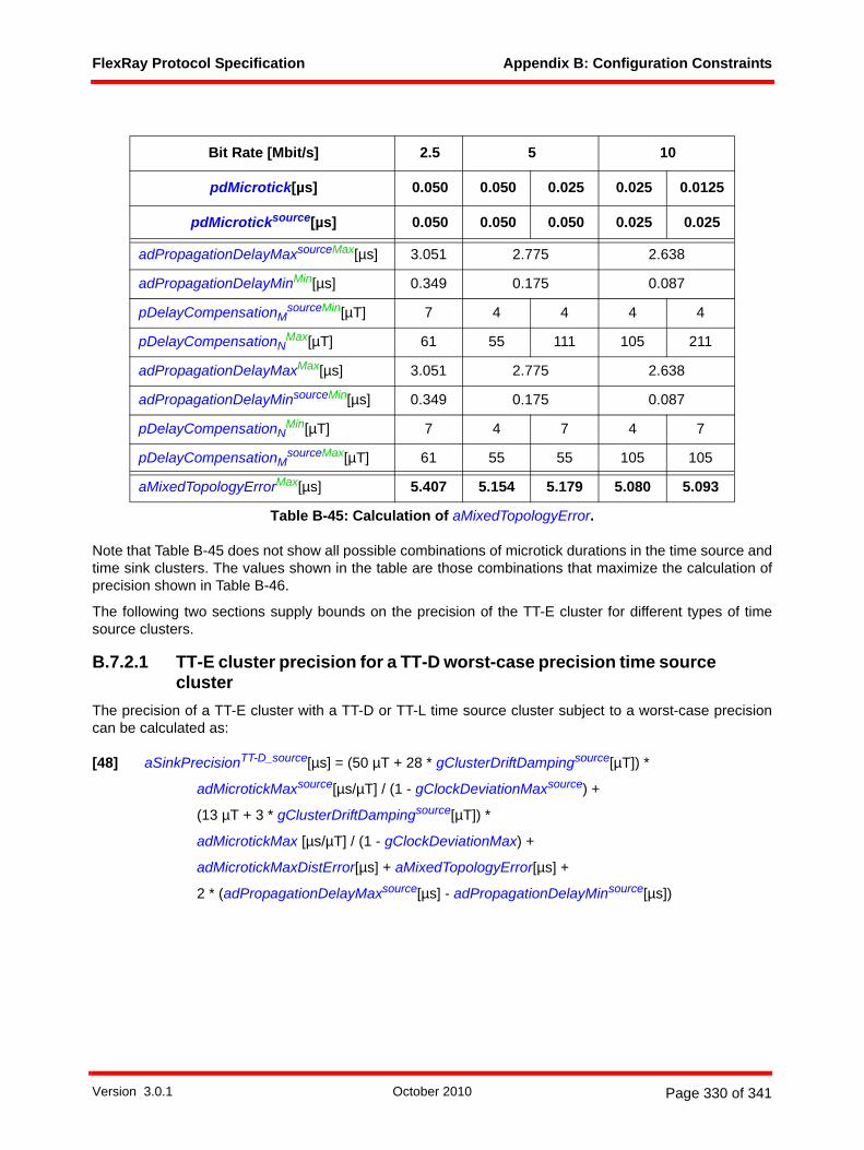
FlexRay Protocol Specification Appendix B: Configuration Constraints
Note that Table B-45 does not show all possible combinations of microtick durations in the time source andtime sink clusters. The values shown in the table are those combinations that maximize the calculation ofprecision shown in Table B-46.
The following two sections supply bounds on the precision of the TT-E cluster for different types of timesource clusters.
B.7.2.1 TT-E cluster precision for a TT-D worst-case precision time source cluster
The precision of a TT-E cluster with a TT-D or TT-L time source cluster subject to a worst-case precisioncan be calculated as:
[48] aSinkPrecisionTT-D_source[µs] = (50 µT + 28 * gClusterDriftDampingsource[µT]) *
adMicrotickMaxsource[µs/µT] / (1 - gClockDeviationMaxsource) +
(13 µT + 3 * gClusterDriftDampingsource[µT]) *
adMicrotickMax [µs/µT] / (1 - gClockDeviationMax) +
adMicrotickMaxDistError[µs] + aMixedTopologyError[µs] +
2 * (adPropagationDelayMaxsource[µs] - adPropagationDelayMinsource[µs])
Bit Rate [Mbit/s] 2.5 5 10
pdMicrotick[µs] 0.050 0.050 0.025 0.025 0.0125
pdMicroticksource[µs] 0.050 0.050 0.050 0.025 0.025
adPropagationDelayMaxsourceMax[µs] 3.051 2.775 2.638
adPropagationDelayMinMin[µs] 0.349 0.175 0.087
pDelayCompensationMsourceMin[µT] 7 4 4 4 4
pDelayCompensationNMax[µT] 61 55 111 105 211
adPropagationDelayMaxMax[µs] 3.051 2.775 2.638
adPropagationDelayMinsourceMin[µs] 0.349 0.175 0.087
pDelayCompensationNMin[µT] 7 4 7 4 7
pDelayCompensationMsourceMax[µT] 61 55 55 105 105
aMixedTopologyErrorMax[µs] 5.407 5.154 5.179 5.080 5.093
Table B-45: Calculation of aMixedTopologyError.
Version 3.0.1 October 2010 Page 330 of 341

FlexRay Protocol Specification Appendix B: Configuration Constraints
B.7.2.2 TT-E cluster precision for a TT-L time source clusterThe precision for TT-E cluster with TT-L time source cluster subject to a best-case precision can becalculated as:
[49] aSinkPrecisionTT-L_source[µs] =
19 µT * adMicrotickMaxsource[µs/µT] / (1 - gClockDeviationMaxsource) +
13 µT * adMicrotickMax[µs/µT] / (1 - gClockDeviationMax) +
adMicrotickMaxDistError[µs] + aMixedTopologyError[µs] +
(adPropagationDelayMaxsource[µs] - adPropagationDelayMinsource[µs])
B.7.2.3 TT-E assumed precisionAs a consequence of the different way of calculating the lower bound, Constraint 5 is replaced by
Constraint 63: aAssumedPrecision[µs] >= aSinkPrecision[µs]
It is recommended that the assumed precision for the TT-E cluster be set to the value for aSinkPrecision forthe appropriate source cluster type (i.e., according to B.7.2.1 if the time source cluster is a TT-D cluster, and
Bit Rate [Mbit/s] 2.5 5 10
adMicrotickMax[µs] 0.050 0.050 0.025 0.025 0.0125
adMicrotickMaxsource[µs] 0.050 0.050 0.050 0.025 0.025
gClusterDriftDampingsourceMax[µT] 5
aMixedTopologyErrorMax[µs] 5.407 5.154 5.179 5.080 5.093
adPropagationDelayMaxsourceMax[µs] 3.051 2.775 2.638
adPropagationDelayMinsourceMin[µs] 0.349 0.175 0.087
aSinkPrecisionTT-D_sourceMax[µs] 21.777 21.320 20.619 15.665 15.315
Table B-46: Calculation of maximum precision in a sink cluster.
Bit Rate [Mbit/s] 2.5 5 10
adMicrotickMax[µs] 0.050 0.050 0.025 0.025 0.0125
adMicrotickMaxsource[µs] 0.050 0.025 0.025 0.0125 0.0125
aMixedTopologyErrorMin[µs] 0
min( adPropagationDelayMaxsource[µs] - adPropagationDelayMinsource[µs] ) 0
aSinkPrecisionTT-L_sourceMin[µs] 1.652 1.177 0.826 0.588 0.413
Table B-47: Calculation of the minimum precision in a sink cluster.
Version 3.0.1 October 2010 Page 331 of 341
FlexRay Protocol Specification Appendix B: Configuration Constraints
according to B.7.2.2 if the source cluster is a TT-L cluster). [Ung09] gives more detail about the relationshipbetween the time source cluster and time sink cluster that can be used to improve the precision estimatebut goes beyond the scope and intent of the specification.
Note that the calculations for aSinkPrecision make the assumption that if external clock correction is usedin the time source cluster (i.e., gExternOffsetCorrection or gExternRateCorrection are non-zero for the timesource cluster) that corresponding external correction terms are also applied in the non-sync nodes in thetime sink cluster, and that the application of those external corrections take place at the same time as in thetime source cluster.
Parameter ranges in this specification are calculated assuming that the maximum value of aAssumedPre-cision is calculated using the worst case value for the assumed precision of a TT-D source cluster (seesection B.4.2.5) and then applying Constraint 63 as an equality constraint. The configurable range of mostparameters allows some amount of margin beyond this assumption. If a system designer of a TT-E clusterdesires to use a value of aAssumedPrecision larger than the value of aSinkPrecision the resultantparameters must be carefully checked to ensure that they are still within the allowed parameter ranges.
B.7.3 pSecondKeySlotIDThe configuration of pSecondKeySlotID for nodes operating in TT-E clusters is identical to the configurationof pSecondKeySlotID for nodes operating in TT-L clusters. Please refer to section B.6.3 and Constraint 60and Constraint 61 for the configuration of this parameter.
B.7.4 Host-controlled external clock correctionIn most cases the timing of a TT-E cluster is fully determined by the timing of the time source cluster andthus it is usually not necessary to make use of host-controlled external clock correction in a TT-E cluster. If,however, the time source cluster makes use of host-controlled external clock correction it may also bedesirable for the time sink cluster to make a corresponding host-controlled external clock correction. If sucha correction is used it should have the same value as the correction in the time source cluster, and shouldbe applied in the same cycle as the correction in the time source cluster.
Constraint 64: gExternOffsetCorrection[µs] = gExternOffsetCorrectionsource[µs]
Constraint 65: gExternRateCorrection[µs] = gExternRateCorrectionsource[µs]
Although the non-sync nodes in the time sink cluster need to apply host-controlled external clock correctionsin the indicated circumstances, the coldstart nodes for the TT-E cluster (i.e., the time gateway sink) shouldnot perform any host-controlled external clock correction, as the clock correction from the time gatewaysource is imported into the time gateway sink by the CSP process (see Figure 8-21). As a result, the localexternal correction terms for the time gateway sink should be set to zero:
Constraint 66: pExternOffsetCorrectionGWsink[µT] = 0 µT
Constraint 67: pExternRateCorrectionGWsink[µT] = 0 µT
B.7.5 gdActionPointOffsetDue to being tightly coupled to the time source cluster, Constraint 13 is superfluous and must not be appliedto TT-E clusters. Constraint 12 remains valid.
Version 3.0.1 October 2010 Page 332 of 341

FlexRay Protocol Specification Appendix B: Configuration Constraints
B.7.6 gMacroPerCycleThe constraints of section B.4.14 remain valid. In addition the following constraint must be observed.
Constraint 68: gMacroPerCycle[MT] = gMacroPerCyclesource[MT]
This constraint puts implicit constraints on the configuration of the schedule of the time sink cluster.
B.7.7 gdMacrotickThe constraints of section B.4.4 remain valid. In addition the following constraint must be observed.
Constraint 69: gdMacrotick[µs] = gdMacroticksource[µs]
B.7.8 aOffsetCorrectionMaxConstraint 30 as well as equation [28] and [29] remain valid for TT-E systems. In order to compute an upperbound on the possible range of offset corrections the following equation should be used instead of equation[30]:
[50] aOffsetCorrectionMax[µs] <= max(
aNegativeOffsetCorrectionMax[µs] ; aPositiveOffsetCorrectionMax[µs] ;
aNegativeOffsetCorrectionMaxsource[µs] ; aPositiveOffsetCorrectionMaxsource[µs] )
B.7.9 pOffsetCorrectionStartThe constraints and formulas of sections B.4.20 remain valid. Constraint 32 remains valid for non-syncnodes; for the time gateway sink node, it is replaced by
Constraint 70: pOffsetCorrectionStartGWsink = pOffsetCorrectionStartGWsource
B.7.10 gdNITConsider the following assumption:
• The offset correction has to be applied within the NIT. To ensure this the following constraint has tobe fulfilled.
Constraint 71: gdNIT[MT] >= max( adRemRateCalculation[MT]; adRemOffsetCalculation[MT] +
adOffsetCorrection[MT]; adRemOffsetCalculation[MT] + adOffsetCorrectionsource[MT] )
B.7.11 pdMicrotickConsider the following assumption:
• The time gateway source node transfers its rate and offset correction values to the time gatewaysink node. As the unit of these correction values is [µT], the time gateway sink node needs to usethe same microtick length as the time gateway source node to correctly interpret the values.
The constraints of section B.4.4 remain valid. In addition the following constraint must be observed.
Constraint 72: pdMicrotickGWsink[µs] = pdMicrotickGWsource[µs]
Version 3.0.1 October 2010 Page 333 of 341
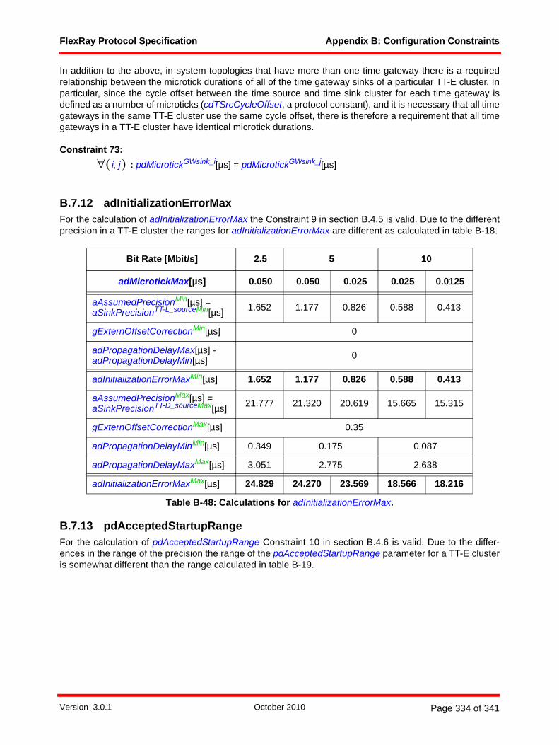
FlexRay Protocol Specification Appendix B: Configuration Constraints
In addition to the above, in system topologies that have more than one time gateway there is a requiredrelationship between the microtick durations of all of the time gateway sinks of a particular TT-E cluster. Inparticular, since the cycle offset between the time source and time sink cluster for each time gateway isdefined as a number of microticks (cdTSrcCycleOffset, a protocol constant), and it is necessary that all timegateways in the same TT-E cluster use the same cycle offset, there is therefore a requirement that all timegateways in a TT-E cluster have identical microtick durations.
Constraint 73: : pdMicrotickGWsink_i[µs] = pdMicrotickGWsink_j[µs]
B.7.12 adInitializationErrorMaxFor the calculation of adInitializationErrorMax the Constraint 9 in section B.4.5 is valid. Due to the differentprecision in a TT-E cluster the ranges for adInitializationErrorMax are different as calculated in table B-18.
B.7.13 pdAcceptedStartupRangeFor the calculation of pdAcceptedStartupRange Constraint 10 in section B.4.6 is valid. Due to the differ-ences in the range of the precision the range of the pdAcceptedStartupRange parameter for a TT-E clusteris somewhat different than the range calculated in table B-19.
Bit Rate [Mbit/s] 2.5 5 10
adMicrotickMax[µs] 0.050 0.050 0.025 0.025 0.0125
aAssumedPrecisionMin[µs] = aSinkPrecisionTT-L_sourceMin[µs] 1.652 1.177 0.826 0.588 0.413
gExternOffsetCorrectionMin[µs] 0
adPropagationDelayMax[µs] - adPropagationDelayMin[µs] 0
adInitializationErrorMaxMin[µs] 1.652 1.177 0.826 0.588 0.413
aAssumedPrecisionMax[µs] = aSinkPrecisionTT-D_sourceMax[µs] 21.777 21.320 20.619 15.665 15.315
gExternOffsetCorrectionMax[µs] 0.35
adPropagationDelayMinMin[µs] 0.349 0.175 0.087
adPropagationDelayMaxMax[µs] 3.051 2.775 2.638
adInitializationErrorMaxMax[µs] 24.829 24.270 23.569 18.566 18.216
Table B-48: Calculations for adInitializationErrorMax.
i j,( )∀
Version 3.0.1 October 2010 Page 334 of 341

FlexRay Protocol Specification Appendix B: Configuration Constraints
The lower bound of pdAcceptedStartupRange is given by the calculation in a TT-D cluster (see sectionB.4.6, table B-19) and the upper bound by the calculation in a TT-E cluster (table B-49). As a result, theparameter pdAcceptedStartupRange must be configurable over a range of 29 to 2743 µT.
B.7.14 gCycleCountMaxConsider the following assumption:
• gCycleCountMax in the time sink cluster should be identically configured like gCycleCountMax inthe time source cluster.
Constraint 74: gCycleCountMax = gCycleCountMaxsource
Bit Rate [Mbit/s] 2.5 5 10
adMicrotickMax[µs] 0.050 0.050 0.025 0.025 0.0125
aAssumedPrecisionMin[µs] = aSinkPrecisionTT-L_sourceMin[µs] 1.652 1.177 0.826 0.588 0.413
adInitializationErrorMaxMin[µs] 1.652 1.177 0.826 0.588 0.413
pdMicrotickMax[µs] 0.050 0.050 0.025 0.025 0.0125
pdAcceptedStartupRangeMin[µT] 67 48 67 48 67
aAssumedPrecisionMax[µs] = aSinkPrecisionTT-D_sourceMax[µs] 21.777 21.320 20.619 15.665 15.315
adInitializationErrorMaxMax[µs] 24.829 24.270 23.569 18.566 18.216
pdMicrotickMin[µs] 0.050 0.025 0.025 0.0125 0.0125
pdAcceptedStartupRangeMax[µT] 934 1827 1771 2743 2687
Table B-49: Calculations for pdAcceptedStartupRange.
Version 3.0.1 October 2010 Page 335 of 341

FlexRay Protocol Specification Appendix C: Wakeup Application Notes
Appendix CWakeup Application Notes
This appendix contains some application notes related to the coordination of the host microcontroller, theFlexRay communication controller, and the bus drivers during the wakeup process as well as describingsome techniques that can be used to perform wakeup during operation. This appendix is not intended to becomplete, but merely to provide some example strategies that touch on some of the issues that will be facedby a system designer with respect to wakeup coordination.
Note the control and indication behavior of the bus driver is fairly complex. For example, certain indicationsare only available in certain BD operating modes. The descriptions in this appendix are at a high level, i.e.,they merely indicate what needs to be done without explicitly indicating the detailed BD commands, modes,indications, etc. necessary to do it. Refer to [EPL10] for additional details.
C.1 Wakeup initiation by the hostA host that wants to initiate a wakeup of the cluster should first check its bus driver(s) to see if they havereceived wakeup patterns. If the bus driver of a channel did not receive a wakeup pattern, and if there is nostartup or communication in progress, the host shall try to wake this channel209.
The host should not wake channels whose bus drivers have received a wakeup pattern unless additionalinformation indicates that startup is not possible without an additional wakeup of those channels.210
A single-channel node in a dual-channel cluster can trigger a cluster wakeup by waking its attachedchannel. This wakes up all nodes attached to this channel, including the coldstart nodes, which are alwaysdual-channel. Any coldstart node that deems a system startup necessary will then wake the remainingchannel before initiating communication startup.
C.1.1 Single-channel nodesThis section describes the wakeup behavior of single-channel nodes in single- or dual-channel clusters. Thebus driver is assumed to be in the BD_Sleep or BD_Standby mode. The host is assumed to havedetermined that a cluster wakeup should be triggered.
1. The host first configures the communication controller.2. The host checks whether a wakeup pattern was received by the bus driver.3. The host puts the bus driver into the BD_Normal mode.4. If a wakeup pattern was received by the bus driver, the node should enter the startup (step 8) instead
of performing a wakeup. If no wakeup pattern was received by the bus driver, the node may perform a wakeup of the attached channel (which will eventually wake both channels of a dual-channel cluster).
5. The host configures pWakeupChannel to the attached channel.6. The host commands the communication controller to begin the wakeup procedure.7. After its wakeup attempt is complete the communication controller returns the result of the wakeup
attempt.
209 The host must distinguish between a local wakeup event and a remote wakeup received via the channel. This information is accessible at the bus driver.
210 This is done to speed up the wakeup process and to limit the amount of traffic on the channels, which reduces the number of collisions during this phase.
Version 3.0.1 October 2010 Page 336 of 341

FlexRay Protocol Specification Appendix C: Wakeup Application Notes
8. The host commands the communication controller to commence startup and, possibly after a delay (see section C.4), to leave the coldstart inhibit mode.
C.1.2 Dual-channel nodesThis section describes the wakeup behavior of dual-channel nodes in dual-channel clusters.
Figure C-1: A short example of how the wakeup of two channels can be accomplished in a fault-tolerant way by coldstart nodes.211
A communication controller is not allowed to send a wakeup pattern on both channels at the same time. Ifit is necessary to wake both channels, the host can only wake them one at a time.
To avoid certain types of failures, a single communication controller should not wake up both channels.Instead, a different controller should wake up each channel.
To accomplish this, a communication controller that has received a local wakeup event proceeds normallyand only wakes a single channel, e.g., channel A (see Figure C-1). The completion of the wakeup causesthe node to enter the POC:ready state, and also causes the node to automatically enter the coldstart inhibitmode. Following this, the host does not wake the other channel but rather enters startup. The host shouldkeep the node in the coldstart inhibit mode until it detects a wakeup pattern on channel B. Once a wakeupis detected, the host should issue the ALLOW_COLDSTART command, allowing the node to activelycoldstart the cluster.
Two example wakeup strategies are now given as examples to demonstrate how cluster wakeup can beaccomplished. These strategies are not concerned with the details of error recovery and therefore do notshow error handling mechanisms for several error situations that could occur.
C.1.2.1 Wakeup pattern reception by the bus driverThe bus drivers are assumed to be in the BD_Sleep or BD_Standby mode. The host is assumed to havedetermined that a cluster wakeup should be triggered.
1. The host first configures the communication controller. It assumes both channels to be asleep.2. The host checks which of the bus drivers has received a wakeup pattern.3. The host puts all bus drivers that have received a wakeup pattern into BD_Normal mode (these chan-
nels can be assumed to be awake).
211 Note that there is no requirement that a wakeup node be a coldstart node, or that a coldstart node be a wakeup node. In this example the wakeup nodes are also coldstart nodes, but this is not required.
power off / reset
power off / reset
poweroff/reset
POC state
config
Node Awakeup/coldstart nodechannel A, B
Node Cnon-coldstart nodechannel B
Channel A
B
wakeup listen
wakeup send
wakeuppattern
wakeuppattern
ready wakeup listen
wakeup send integration listenreadyconfig
ready ready coldstart listenNode Bwakeup/coldstart nodechannel A, B
coldstart listen
leave coldstartinhibit mode
wakechannel A
wake channel B
config ready integration listen
localwakeup event
Version 3.0.1 October 2010 Page 337 of 341

FlexRay Protocol Specification Appendix C: Wakeup Application Notes
4. If both channels are awake, the host can proceed to startup (step 10).If both channels are asleep, the host shall wake up one of them.If one channel is asleep and one channel is awake, a non-coldstart host may wake up the channel that is asleep, but a coldstart host must wake up the channel that is asleep.
5. The host configures pWakeupChannel to the channel to be awakened.6. The host puts the bus driver of pWakeupChannel into BD_Normal mode.7. The host commands the communication controller to begin the wakeup procedure.8. The communication controller returns the result of the wakeup attempt.9. If the result of the wakeup attempt is TRANSMITTED, the host assumes pWakeupChannel to be
awake and proceeds to startup (step 10).If the result of the wakeup attempt is RECEIVED_HEADER or COLLISION_HEADER, the host can assume that both channels are awake. It puts any remaining sleeping bus driver into BD_Normal mode and proceeds to startup (step 10).If the result of the wakeup attempt is RECEIVED_WUP or COLLISION_WUP, the host assumes pWakeupChannel to be awake (return to step 4).If the result of the wakeup attempt is COLLISION_UNKNOWN, an application-specific recovery strat-egy has to be employed, which is not covered by this document.
10. The host commands the communication controller to begin the startup procedure.11. If all channels are awake, the host may immediately command the communication controller to leave
the coldstart inhibit mode by issuing an ALLOW_COLDSTART command. Otherwise, the host should leave the CC in coldstart inhibit mode and wait until the bus driver of the still sleeping channel signals the reception of a wakeup pattern. This bus driver shall then be put into the BD_Normal mode. As soon as all attached channels are awake, the host may command the communication controller to leave the coldstart inhibit mode.
This method has the disadvantage that the channel that is not pWakeupChannel cannot be listened toduring the POC:wakeup listen state. If the bus driver of pWakeupChannel channel is subject to an incominglink failure, ongoing communication might be disturbed.
C.1.2.2 Wakeup pattern reception by the communication controllerThe wakeup pattern receiver of the communication controller is active as long as the CODEC is in READYor NORMAL mode. During this time the reception of a wakeup pattern will be signaled to the FSP and fromthere to the CHI.
The bus drivers are assumed to be in the BD_Sleep or BD_Standby modes. The host is assumed to havedetermined that a cluster wakeup should be triggered.
1. The host first configures the communication controller. It assumes both channels to be asleep.2. The host checks which of the bus drivers has received a wakeup pattern.3. The host puts both bus drivers into BD_Normal mode.4. If both channels are awake, the host can proceed to startup (step 10).
If both channels are asleep, the host shall awake one of them.If one channel is asleep and one channel is awake, a non-coldstart host may wake up the channel that is asleep, but a coldstart host must wake up the channel that is asleep.
5. The host configures pWakeupChannel to the channel that to be awakened.6. The host commands the communication controller to begin the wakeup procedure.7. The communication controller returns the result of the wakeup attempt.8. If the result of the wakeup attempt is TRANSMITTED, the host assumes pWakeupChannel to be
awake and proceeds to startup (step 10).If the result of the wakeup attempt is RECEIVED_HEADER or COLLISION_HEADER, the host assumes all attached channels to be awake and proceeds to startup (step 10).
Version 3.0.1 October 2010 Page 338 of 341

FlexRay Protocol Specification Appendix C: Wakeup Application Notes
If the result of the wakeup attempt is RECEIVED_WUP or COLLISION_WUP, the host assumes pWakeupChannel to be awake (return to step 4).If the result of the wakeup attempt is COLLISION_UNKNOWN, an application-specific recovery strat-egy has to be employed, which is not covered here.
9. The host commands the communication controller to begin the startup procedure.10. If all channels are awake, the host may immediately command the communication controller to leave
the coldstart inhibit mode by issuing an ALLOW_COLDSTART command. Otherwise, the host should leave the CC in the coldstart inhibit mode and wait until the wakeup pattern detector of the communi-cation controller detects a wakeup pattern on the channel that is assumed to be asleep (this could already have occurred during one of the former steps). Once a wakeup pattern is detected the channel is assumed to be awake. As soon as all attached channels are awake, the host may command the communication controller to leave the coldstart inhibit mode.
C.2 Host reactions to status flags signaled by the communication controller
This section defines the status information that the communication controller can return to the host as resultof its wakeup attempt and the recommended reaction of the host.
C.2.1 Frame header reception without decoding errorWhen a frame header without decoding error is received by the communication controller on either availablechannel while in the POC:wakeup listen (or POC:wakeup detect) state the communication controller abortsthe wakeup, even if channel pWakeupChannel is still silent.
The host shall not command the communication controller to initiate additional wakeup attempts, since thiscould disturb ongoing communication. Instead, it shall command the communication controller to enter thestartup to integrate into the apparently established cluster communication.
C.2.2 Wakeup pattern receptionThe communication controller has received a wakeup pattern on channel pWakeupChannel while in thePOC:wakeup listen (or POC:wakeup detect) state. This indicates that another node is already waking upthis channel. To prevent collisions of wakeup patterns on channel pWakeupChannel, the communicationcontroller aborts the wakeup.
If another channel is available that is not already awake, the host must determine whether the communi-cation controller is to wake up this channel. If all available channels are awake, the host shall command thecommunication controller to enter startup.
C.2.3 Wakeup pattern transmissionThe communication controller has transmitted the complete wakeup pattern on channel pWakeupChannel.The node can now proceed to startup.
C.2.4 Termination due to unsuccessful wakeup pattern transmissionThe communication controller was not able to transmit a complete wakeup pattern because its attempt totransmit it resulted in at least cdWakeupMaxCollision occurrences of continuous logical LOW during the idlephase of a wakeup pattern. Possible reasons for this are heavy EMI disturbances on the bus or an internalerror.212
212 The collision of a wakeup pattern transmitted by this node with another wakeup pattern generated by a fault-free node will generally not result in this exit condition. Such a collision can be recognized after entering the POC:wakeup detect state and would be signaled by setting the variable vPOC!WakeupStatus to COLLISION_WUP.
Version 3.0.1 October 2010 Page 339 of 341

FlexRay Protocol Specification Appendix C: Wakeup Application Notes
Since no complete wakeup pattern has been transmitted, it cannot be assumed that all nodes have receiveda wakeup pattern. The host may use the retransmission procedure described in section C.3.
C.3 Retransmission of wakeup patternsSome events or conditions may prevent a cluster from waking up even though a wakeup attempt has beenmade (possibly even without the transmitting communication controller being able to immediately detect thisfailure213). The host detects such an error when the cluster does not start up successfully after the wakeup.
The host may then initiate a retransmission of the wakeup pattern. The procedure described in section 7.1.2shall be used to transmit a wakeup pattern on channel pWakeupChannel.
Note that this might disturb ongoing communication of other nodes if the node initiating the wakeupprocedure is subject to an incoming link failure or a fault in the communication controller. The host mustensure that such a failure condition will not lead to a permanent disturbance on the bus.
C.4 Transition to startupIt cannot be assumed that all nodes and stars need the same amount of time to become completely awakeand to be configured.
Since at least two nodes are necessary to start up the cluster communication, it is advisable to delay anypotential startup attempt of the node having initiated the wakeup by the minimal amount of time it takesanother coldstart node to become awake, to be configured, and to enter startup214. Otherwise, the wakeup-initiating coldstart node may fail in its startup attempt with an error condition that is not distinguishable froma defective outgoing link (the communication controller reports no communication partners; see sectionC.3).
The coldstart inhibit mode can be used to effectively deal with this situation. A communication controller inthis mode will only participate in the startup attempts made by other nodes but not initiate one itself. Thecoldstart inhibit mode is set automatically prior to entry to the POC:ready state; the host should not causethe CC to exit this mode (by issuing an ALLOW_COLDSTART command) before the above mentionedminimal time for another node to become ready for the communication startup. However, the host shallissue the ALLOW_COLDSTART command as soon as all coldstart nodes are awake in the fault-freecase215. Please refer to section 7.2.3 for further details of this mode.
C.5 Wakeup during operationThis section describes wakeup during operation methods that a communication controller can use duringthe operation of a cluster to trigger the wakeup of other nodes with BD’s in the sleep or standby mode whenthose BD’s support the optional remote wakeup event detection capability described in [EPL10].
C.5.1 PrinciplesDuring the operation of a FlexRay network it is possible that some nodes do not take part in the normalFlexRay wakeup procedure (e.g. when they power up too late) or have for some reason gone to standby orsleep after they already were part of an ongoing communication (e. g. because of the reset of a node).
213 E.g. an erroneous star that needs significantly more time to start up and to be able to forward messages.214 This parameter depends heavily on implementation details of the components used and the ECU structure.215 If these times are not known at system design time, it is advised to exit the coldstart inhibit mode late rather than early.
Version 3.0.1 October 2010 Page 340 of 341

FlexRay Protocol Specification Appendix C: Wakeup Application Notes
The normal wakeup procedure described in section 7.1 would require a node attempting to wake up othernodes be removed from the normal communication, disrupting the transmission and reception capability ofthat node. In addition, such a wakeup attempt would be unsuccessful because the ongoing communicationin the cluster would cause the abortion of the wakeup procedure before wakeup patterns would be sent. Insuch cases it is necessary that the nodes already in operation be capable of causing other nodes to wakeup without requiring the entire cluster to be shutdown and without disrupting their own communications.
The protocol offers two methods to provide a remote wakeup during normal operation capability:
1. frame-based transmission of a sequence of bus activity2. pattern-based transmission of a pattern
The first method is completely transparent to the protocol operation and is therefore outlined in this section.The second method is explicitly supported by the mechanisms defined for the FlexRay protocol.
C.5.1.1 Frame-based wakeup during operation[EPL10] defines the payload of a FlexRay frame that, when transmitted at a data rate of 10 Mbit/s, isguaranteed to cause a BD in the sleep or standby mode to detect a remote wakeup event. A node can causea wakeup during normal operation by transmitting a frame with this special payload. This can be done ineither the static or the dynamic segment, but in the static segment the entire payload must fit within thepayload length of static frames defined by gPayloadLengthStatic. A node whose BD is in the standby orsleep mode that receives such a frame will signal the reception of a remote wakeup event to the host, andthen operation can proceed as defined in the other sections of this chapter.
Note that the frame payload defined in [EPL10] is only guaranteed to cause a wakeup for systems operatingat 10 Mbit/s. At bit rates of 5 and 2.5 Mbit/s the alternating data pattern of the BSS can interfere with theremote wakeup detection process in the BD's and prevent detection of wakeup attempts based on framepayloads.
During normal operation, the reception of a frame-based wakeup would not be detected by the protocol'swakeup pattern decoding process and thus will not be signaled to the host. The reception of a frame and itspayload will, however, be signaled to the host by the normal reception mechanisms, and this allows somepossibility to verify that other nodes are transmitting frame-based wakeups as expected.
C.5.1.2 Pattern-based wakeup during operationThe FlexRay protocol supports the transmission of a dedicated wakeup during operation pattern (WUDOP)within the symbol window. The WUDOP is described in section 3.2.1.2.3 and will cause the detection of aremote wakeup by BD's regardless of the bit rate of the cluster (i.e., unlike frame-based methods, thepattern-based mechanism will work in systems using bit rates of 5 and 2.5 Mbit/s).
The host has control over the transmission of the WUDOP by means of the mechanisms defined in section9.3.1.2.2. The WUDOP is not collision resilient - the system designer must ensure that no more than onenode transmits a WUDOP in any given instance of the symbol window.
A node whose BD is in the standby or sleep mode that receives a WUDOP will signal the reception of aremote wakeup event to the host, and then operation can proceed as defined in the other sections of thischapter.
During normal operation, the reception of a WUDOP in the symbol window or NIT would be detected by theprotocol's wakeup pattern decoding process and signaled to the host (see section 9.3.1.3.2). This allows anode in operation to verify that other nodes are transmitting WUDOPs as expected.
341
Version 3.0.1 October 2010 Page 341 of 341