FLEISH PENSTOCK AND HIGHLAND INVERTED … not have drawings of the Fleish penstock, but note that...
21
Truckee Meadows Water Authority is a not-for-profit, community-owned water utility, overseen by elected officials and citizen appointees from Reno, Sparks and Washoe County. 1355 Capital Blvd. P.O. Box 30013 Reno, NV 89520-3013 775.834.8080 775.834.8003 P F Addendum No. 1 FLEISH PENSTOCK AND HIGHLAND INVERTED SIPHON STRUCTURAL LINING PWP Bid No. WA-2016-038 October 23, 2015 The following information, clarifications, changes and modifications are by reference incorporated into the bid documents for the above referenced project. Any work item or contract provision not changed or modified will remain in full force and effect. The bid date and time and construction schedule remain the same. QUESTIONS AND RESPONSES Question No. 1: Can you send me any of the pictures of the penstock and siphon we discussed? It is greatly appreciated. Also if you had the actual profiles that’d be good too. Response to Question No. 1: Recent pictures of the Fleish flume, and 2010 pictures of the Highland inverted siphon are attached below. Also attached is a plan and profile of the Highland site. TMWA does not have drawings of the Fleish penstock, but note that penstock slopes are tabulated in the wall thickness survey results in the far-right column of Appendix A of the Bid Package. There are no horizontal offsets or fittings in the penstock, only minor vertical deflections. Contractors are cautioned that the following images are only snapshots and cannot completely represent the condition of each site. It is highly recommended that Contractors perform their own investigations and condition assessments prior to bidding on this project. If a bidder would like to arrange a site visit to gather first-hand information regarding this Project please contact Brent Eisert the Project Representative at 775-843-2301.
Transcript of FLEISH PENSTOCK AND HIGHLAND INVERTED … not have drawings of the Fleish penstock, but note that...

Truckee Meadows Water Authority is a not-for-profit, community-owned water utility,
overseen by elected officials and citizen appointees from Reno, Sparks and Washoe County.
1355 Capital Blvd. P.O. Box 30013 Reno, NV 89520-3013
775.834.8080 775.834.8003
P
F
Addendum No. 1 FLEISH PENSTOCK AND HIGHLAND INVERTED SIPHON
STRUCTURAL LINING
PWP Bid No. WA-2016-038
October 23, 2015
The following information, clarifications, changes and modifications are by reference incorporated into
the bid documents for the above referenced project. Any work item or contract provision not changed or
modified will remain in full force and effect. The bid date and time and construction schedule remain
the same.
QUESTIONS AND RESPONSES
Question No. 1: Can you send me any of the pictures of the penstock and siphon we discussed? It is greatly
appreciated. Also if you had the actual profiles that’d be good too.
Response to Question No. 1: Recent pictures of the Fleish flume, and 2010 pictures of the Highland
inverted siphon are attached below. Also attached is a plan and profile of the Highland site. TMWA
does not have drawings of the Fleish penstock, but note that penstock slopes are tabulated in the wall
thickness survey results in the far-right column of Appendix A of the Bid Package. There are no
horizontal offsets or fittings in the penstock, only minor vertical deflections.
Contractors are cautioned that the following images are only snapshots and cannot completely represent
the condition of each site. It is highly recommended that Contractors perform their own investigations
and condition assessments prior to bidding on this project.
If a bidder would like to arrange a site visit to gather first-hand information regarding this Project please
contact Brent Eisert the Project Representative at 775-843-2301.

Fleish Penstock down to Powerhouse

Forebay on Left Transitioning to Penstock with Vent

Penstock Showing Vertical Deflection - Forebay in Background

Scroll Case Showing Two Access Hatches
Condition Assessment of Truckee River Siphon
16
bending and distortion in the pipe wall. Secondly, the elastic buckling resistance of a pipe is directly proportional to it radius of curvature (i.e. ring stiffness EI/R3) so an increase in the radius with no corresponding increase in pipe thickness is going to reduce the buckling resistance of the structure.
6.0 Visual Inspection of Interior
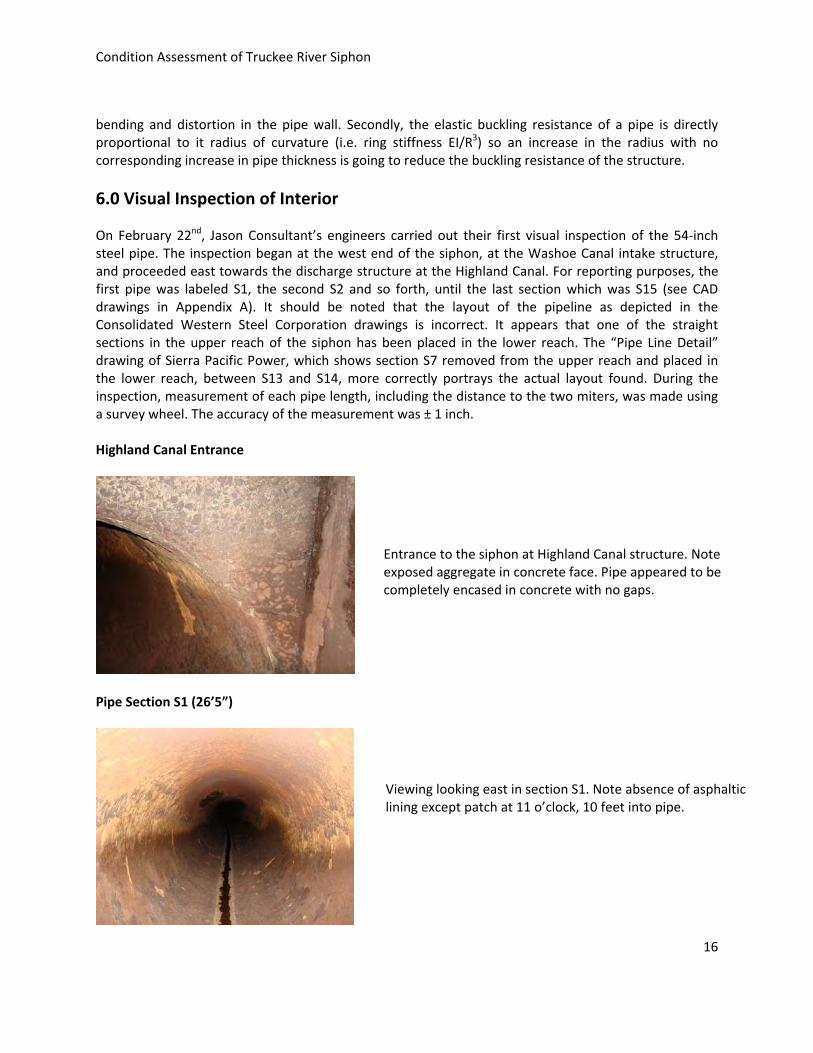
On February 22nd, Jason Consultant’s engineers carried out their first visual inspection of the 54‐inch steel pipe. The inspection began at the west end of the siphon, at the Washoe Canal intake structure, and proceeded east towards the discharge structure at the Highland Canal. For reporting purposes, the first pipe was labeled S1, the second S2 and so forth, until the last section which was S15 (see CAD drawings in Appendix A). It should be noted that the layout of the pipeline as depicted in the Consolidated Western Steel Corporation drawings is incorrect. It appears that one of the straight sections in the upper reach of the siphon has been placed in the lower reach. The “Pipe Line Detail” drawing of Sierra Pacific Power, which shows section S7 removed from the upper reach and placed in the lower reach, between S13 and S14, more correctly portrays the actual layout found. During the inspection, measurement of each pipe length, including the distance to the two miters, was made using a survey wheel. The accuracy of the measurement was ± 1 inch. Highland Canal Entrance
Pipe Section S1 (26’5”)
Entrance to the siphon at Highland Canal structure. Note exposed aggregate in concrete face. Pipe appeared to be completely encased in concrete with no gaps.
Viewing looking east in section S1. Note absence of asphaltic lining except patch at 11 o’clock, 10 feet into pipe.

Condition Assessment of Truckee River Siphon
17
Pipe Section S2 (30’0”)
Heavy general corrosion at 9 to 10 o’clock in S1.
Patch of asphaltic lining in S1. Not adhering to wall and
flaking off.
Dresser coupling between S1 and S2 had a gap of 1” on the invert but was closed at the crown. No leakage noted.
Very little asphaltic lining in first 10 feet of S2. Several holes (popped blisters) in the asphaltic lining. Blisters held water behind the lining and eventually popped releasing water and exposing inner surface.

Condition Assessment of Truckee River Siphon
18
Pipe Section S3 (29’11”)
View of crown of section S2. Note poor condition of asphaltic lining. Lining completely missing below the springline.
Approximately 21 feet into S2, three dimples found in the crown of the pipe. Dimples were between 11:30 and 1:00 o’clock and are probably caused by large rocks or boulders resting on the outside of the pipe. Ultrasonic thickness measurements were later made adjacent to some of these dimples. The thickness was found to be 0.217 to 0.238 inches, or about 13% reduced from the original nominal of 0.25”. Section S2 has also experienced up to 7.1% vertical pipe deflection. The crown appeared flat. Lap welded joint between S2 and S3 looked okay, but had little corrosion protection. The asphaltic lining between 9 and 3 o’clock was loose and corrosion apparent under the lining.
View looking down section S3. Asphaltic lining missing from 3 to 9 o’clock, and also on crown near end of the section.

Condition Assessment of Truckee River Siphon
19
Last 4 feet of S3, asphaltic lining is patchy and pit corrosion on crown noted. Lap welded joint between S3 and S4 appeared okay. Pipe Section S4 (29’6”)
Section S4 is similar to S3, namely missing most of its asphaltic lining. View down section S4. Note that most of the asphaltic lining is gone. Vertical deflections are approximately 6.5%.
Pit corrosion found on the crown and invert (shown) of S4.

Condition Assessment of Truckee River Siphon
20
Pipe Section S5 (28’10”)
Lap welded joint between S4 and S5. Joint still has some asphaltic coating protecting it but missing at 7 o’clock.
The asphaltic lining is pretty much completely gone in S5. The crown of S5 (picture is approximately 3 feet into S5) had considerable general corrosion.
A longitudinal weld on the crown is visible. Lap welded joint between S5 and S6 looked good.

Condition Assessment of Truckee River Siphon
21
Pipe Section S6 (29’8”)
Pipe Section S7 (14’4’ to miter elbow, 16’1” to end of pipe)
Asphaltic lining is very patchy in S6. Corrosion, including pit corrosion, found along the invert. Pipe surface very rough from 4 to 7 o’clock.
Seven (7) ft from the joint with S5, the surface had some light corrosion and was wire brushed. Underlying steel looked okay. Lap welded joint between S6 and S7 looks okay, with no signs of any leakage.
View down S7. Corrosion evident in S7, especially in the invert.
Condition Assessment of Truckee River Siphon
22
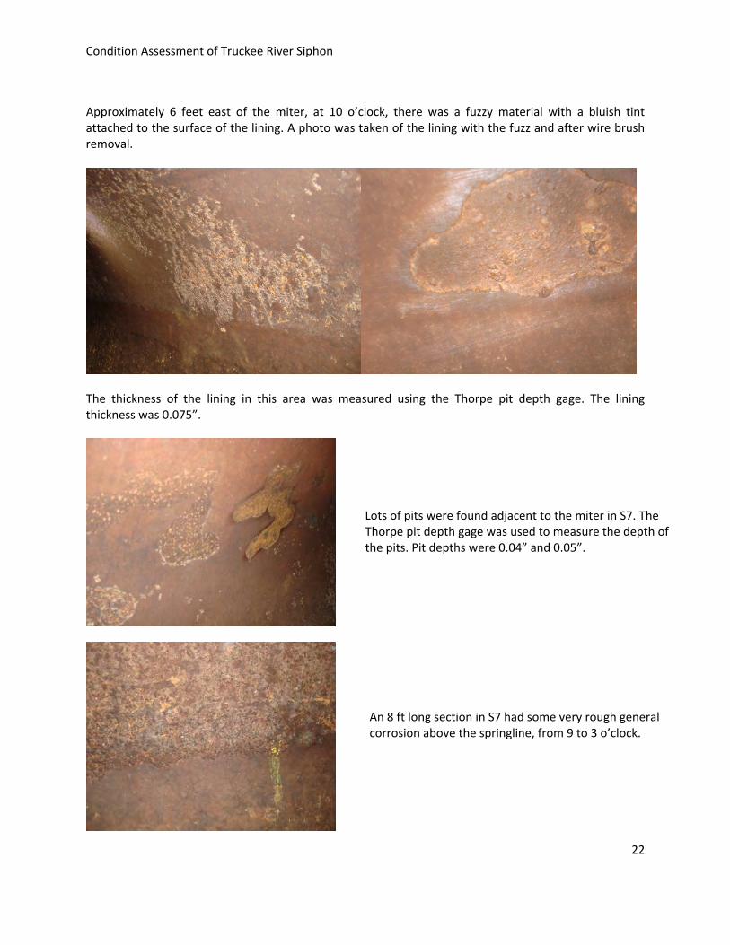
Approximately 6 feet east of the miter, at 10 o’clock, there was a fuzzy material with a bluish tint attached to the surface of the lining. A photo was taken of the lining with the fuzz and after wire brush removal.
The thickness of the lining in this area was measured using the Thorpe pit depth gage. The lining thickness was 0.075”.
Lots of pits were found adjacent to the miter in S7. The Thorpe pit depth gage was used to measure the depth of the pits. Pit depths were 0.04” and 0.05”.
An 8 ft long section in S7 had some very rough general corrosion above the springline, from 9 to 3 o’clock.

Condition Assessment of Truckee River Siphon
23
Pipe Section S8 (29’6”)
The inside surface of S8 showed considerable corrosion around the entire pipe circumference. Pit corrosion was prevalent on the crown, from 9 to 3 o’clock.
Dresser coupling used to join S7 and S8. Asphaltic lining missing from the coupling area. The joint is leaking as wetness was found running up the coupling joint. Enough of an end of a pipe was exposed that it was possible to measure the thickness with a caliper. The thickness was 0.25”. No ultrasonic thickness measurements made here.
The longitudinal welds, 180 degrees apart, were clearly visible in this pipe section as all of the asphaltic lining was gone. The lap welded joint between S8 and S9 did not look good. With no lining protection there was considerable evidence of corrosion at this joint, especially from 9 to 11 o’clock.

Condition Assessment of Truckee River Siphon
24
Pipe Section S9 (30’3”)
S9 had little remaining asphaltic lining as evidenced in this view.
Approximately 6 feet from the end of section S9 there was very heavy corrosion found.
There was also an area on section S9 where the corrosion had a blue tint. We believe this might be indicative of some microbiological attack of the lining. Unfortunately, the blue tint does not show up in the photos.

Condition Assessment of Truckee River Siphon
25
One area where considerable tuberculation or corrosion build up was present was wire brushed to see the condition of the underlying steel.
Before brushing. After brushing – no pits found.
Pipe Section S10 (25’0” to miter elbow, 6’6” to pipe end)
The lap weld joint between S9 and S10 appeared okay, with some corrosion noted on the crown immediately adjacent to the joint.
The asphaltic lining appeared intact from 7 to 1 o’clock. Some mud cracks were observed, however.
Condition Assessment of Truckee River Siphon
26
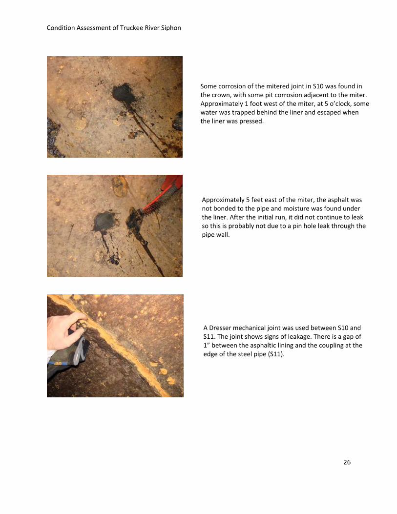
Some corrosion of the mitered joint in S10 was found in the crown, with some pit corrosion adjacent to the miter. Approximately 1 foot west of the miter, at 5 o’clock, some water was trapped behind the liner and escaped when the liner was pressed.
Approximately 5 feet east of the miter, the asphalt was not bonded to the pipe and moisture was found under the liner. After the initial run, it did not continue to leak so this is probably not due to a pin hole leak through the pipe wall.
A Dresser mechanical joint was used between S10 and S11. The joint shows signs of leakage. There is a gap of 1” between the asphaltic lining and the coupling at the edge of the steel pipe (S11).

Condition Assessment of Truckee River Siphon
27
Pipe Section S11 (30’0”)
The asphaltic lining was still in place from 7 to 3 o’clock in this section. Four feet from the joint with S10, an area with corrosion build‐up was wire brushed to see the underlying steel surface. After brushing, the steel looked pit free in this area.
Approximately 23 feet into S11 there was lots of pit and general corrosion in the haunch area between 3 and 4 o’clock. Pit corrosion was also found on the crown of S11.
A lap welded joint connects S11 to S12. There was evidence of corrosion of the joint between 9 and 12 o’clock where the asphalt lining was missing.
Condition Assessment of Truckee River Siphon
28
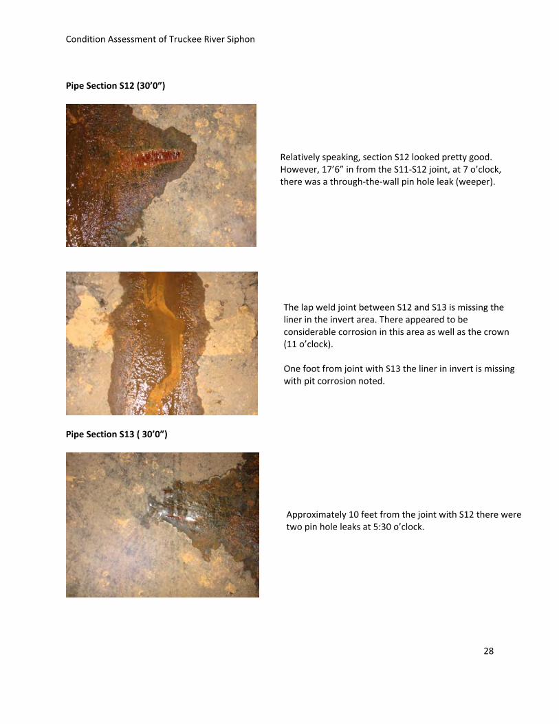
Pipe Section S12 (30’0”)
Pipe Section S13 ( 30’0”)
Relatively speaking, section S12 looked pretty good. However, 17’6” in from the S11‐S12 joint, at 7 o’clock, there was a through‐the‐wall pin hole leak (weeper).
The lap weld joint between S12 and S13 is missing the liner in the invert area. There appeared to be considerable corrosion in this area as well as the crown (11 o’clock). One foot from joint with S13 the liner in invert is missing with pit corrosion noted.
Approximately 10 feet from the joint with S12 there were two pin hole leaks at 5:30 o’clock.
Condition Assessment of Truckee River Siphon
29
Pipe Section S14 (30’0”)
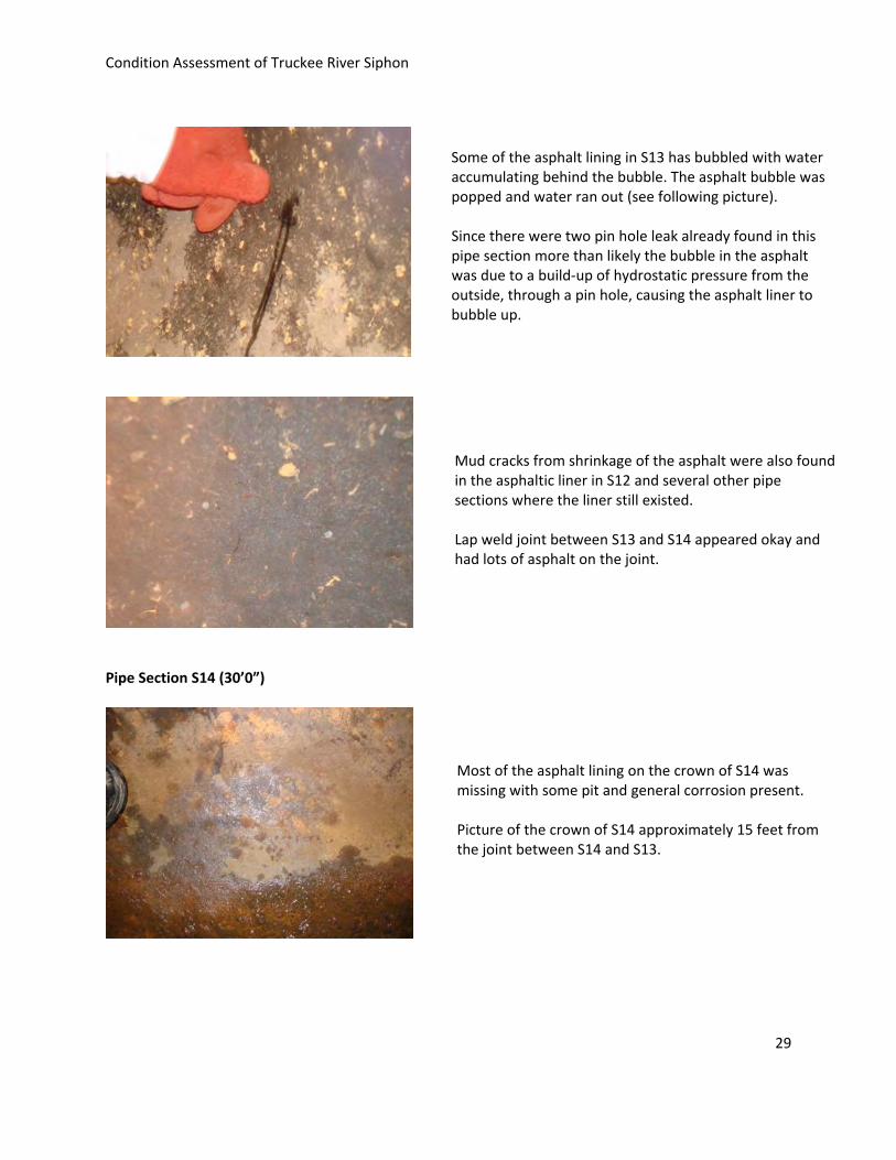
Some of the asphalt lining in S13 has bubbled with water accumulating behind the bubble. The asphalt bubble was popped and water ran out (see following picture). Since there were two pin hole leak already found in this pipe section more than likely the bubble in the asphalt was due to a build‐up of hydrostatic pressure from the outside, through a pin hole, causing the asphalt liner to bubble up.
Mud cracks from shrinkage of the asphalt were also found in the asphaltic liner in S12 and several other pipe sections where the liner still existed. Lap weld joint between S13 and S14 appeared okay and had lots of asphalt on the joint.
Most of the asphalt lining on the crown of S14 was missing with some pit and general corrosion present. Picture of the crown of S14 approximately 15 feet from the joint between S14 and S13.


End of Addendum #1