
Fleet Products - maycoba.com · visit for detailed information. 2 ... crimp fittings Cab TILT...
19
Fleet Products Catalog 3460, September 2014
Transcript of Fleet Products - maycoba.com · visit for detailed information. 2 ... crimp fittings Cab TILT...

Fleet Products
Catalog 3460, September 2014
Contact your authorized Parker Fleet Distributor for ordering, catalogs and further information or visit www.parker.com for detailed information.
1
Table of Contents
Introduction
Rubber Hose ............................................................................A
Thermoplastic Hose .................................................................B
Silicone Hose ............................................................................C
Reusable Hose Fittings ............................................................D
Permanent Hose Fittings ..........................................................E
Adapters ................................................................................... F
Brass Fittings ........................................................................... G
Brass Valves .............................................................................H
Air Brake Products ..................................................................... I
Thermoplastic Tubing ............................................................... J
Quick Couplings Pneumatic .....................................................K
Quick Couplings Hydraulic ....................................................... L
Tools, Test Equipment, Accessories & Storage ....................... M
Hose Assembly Instructions .....................................................N
General Information & Cross-Reference Data ......................... O
Standards & Approvals; Alphanumeric Index ...........................P

Contact your authorized Parker Fleet Distributor for ordering, catalogs and further information or visit www.parker.com for detailed information.
2
Dimensions and pressures are for reference only and are subject to change.
Intr
od
ucti
on
: S
yste
m C
ove
rag
e Parker System Coverage:Complete system coverage—this is what the Parker name means to the transportation and mobile equipment industry today.
Designed and engineered for nearly all heavy-duty truck and mobile equipment applications, Parker system coverage includes:• Cooling and heating systems• Air intake system• Power steering systems• Air-conditioning systems• Cab tilt system• Air systems (air brake, secondary air systems,
tractor/trailer connections)• Fuel and Lube systems• Hydrostatic circuits• Non-conductive applications on aerial lift trucks• Hydraulic systems in general on mobile equipment
Because of their consistent quality and complete system coverage, Parker products have become the standard to the trucking and mobile equipment industry.
Application Recommended
Cooling Systems and Heating lines
293 or 848 hose; Coolant Hose: Series 6621, 6623, 7395; Heater Hose: Series 6722, 6723, 6724, 6750, 6751, 7181, 7186
(Antifreeze at low pressure)
Cooling System & Heating Lines
Application Recommended
Air conditioning (Freon 12)1/8" 60 Series quick couplings
Air conditioning (Freon 134A)285 hose and 26 Series crimp fittings
Cab TILT System (Hydraulic oil up to 2000 psi)
201, 540N-4 hose and 20 & 55 Series fittings
Application Recommended
Hydraulic oil up to 2500 psi (High temp. sometimes exists)
201, 206, 266PKR and 20 Series fittings; 426 or 436 hose and 43 Series fittings
Return line (No pressure)261, 293 & 213PKR hose; Series 7399 (non-SAE hose); PD couplers
Air Conditioning & Cab Lift Systems
Power Steering
Link to Detailed Table of ContentsLink to Master Table of Contents

Contact your authorized Parker Fleet Distributor for ordering, catalogs and further information or visit www.parker.com for detailed information.
3
Dimensions and pressures are for reference only and are subject to change.
Intr
od
ucti
on
: S
yste
m C
ove
rag
e
Application Recommended
Hydrostatic circuits Pressure over 4000 psi
772ST or 782ST hose and 71 or 78 Series fittings; for 2" six-wire hose use P35-32 hose S6 Series fittings
All other hydraulic functions Pressures typically less than 3000 psi
302, 436, or 451ST hose and 43 Series fittings; 520N, 590, D6R hose and 56 Series fittings; for non-conductive applications use 518C hose and 55 Series fittings
Mobile Equipment Hydraulic Systems
Air Systems
Application Recommended
Valve on cab (Compressed air 80-120 psi)
Brakcoil® 731516 or 751641
Valve low on cab at frame rail level or remote from cab (Compressed air 80-120 psi)
Brakcoil® 731522 (With pogo stick or spring hanger)
Tractor to Trailer
Application Recommended
Mainline piping on chassis (Compressed air 80-120 psi)
201 or 213 hose and fittings; 271 hose and fittings; 1120 Air Brake tubing and NTA fittings; PFT tubing; PMT, PTC and NTA fittings
Complete chassis air brake system except compressor line
201 and 293 hose and 26 Series crimp ftittings; 1120 Air Brake tubing and NTA fittings
Compressor discharge to storage tank (Hot compressed air to 120 psi & 400° F)
919 Teflon hose and 90 Series reusable fittings or 91N Series crimp fittings
Air Brake
Fuel & Lube SystemsApplication Recommended
Fuel Lines (Hose compatible with diesel fuel-low pressure some suction)
201 or 293 hose and 26 Series crimp fittings, or 201 hose and Series 389, 395, 397 hose; HTFL tubing and NTA fittings
Lube Filter System (Lube oil can reach 230° F-high temp. 300° hose should be used)
20 Series reusable fittings
Application Recommended
Shutter Stat, Windshield, wipers, horn, shift system, etc.
1120 Air Brake tubing; NTA, PMT, PTC and PLP fittings
Secondary Air Systems
Link to Detailed Table of ContentsLink to Master Table of Contents
Contact your authorized Parker Fleet Distributor for ordering, catalogs and further information or visit www.parker.com for detailed information.
4
Intr
od
ucti
on
: D
etai
led
Tab
le o
f C
ont
ents Detailed Table of Contents
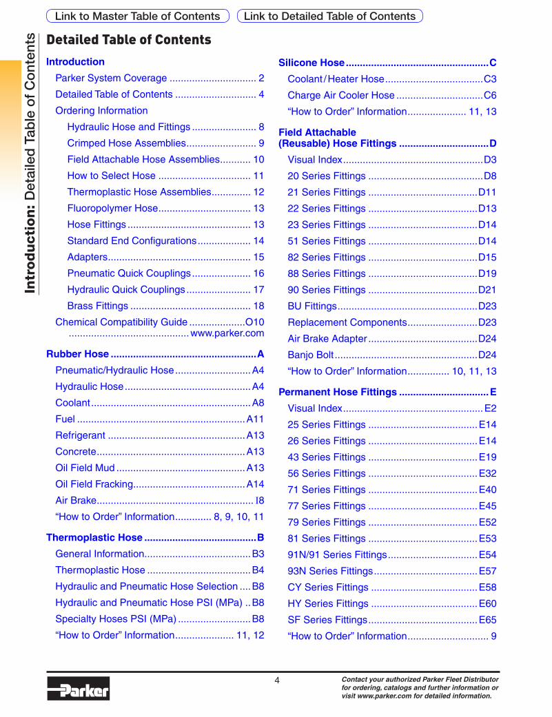
Introduction
Parker System Coverage ............................... 2
Detailed Table of Contents ............................. 4
Ordering Information
Hydraulic Hose and Fittings ....................... 8
Crimped Hose Assemblies ......................... 9
Field Attachable Hose Assemblies ........... 10
How to Select Hose ................................. 11
Thermoplastic Hose Assemblies .............. 12
Fluoropolymer Hose ................................. 13
Hose Fittings ............................................ 13
Standard End Configurations ................... 14
Adapters ................................................... 15
Pneumatic Quick Couplings ..................... 16
Hydraulic Quick Couplings ....................... 17
Brass Fittings ........................................... 18
Chemical Compatibility Guide ....................O10 ...........................................www.parker.com
Rubber Hose ....................................................A
Pneumatic/Hydraulic Hose ...........................A4
Hydraulic Hose .............................................A4
Coolant .........................................................A8
Fuel ............................................................A11
Refrigerant .................................................A13
Concrete .....................................................A13
Oil Field Mud ..............................................A13
Oil Field Fracking ........................................A14
Air Brake ........................................................ I8“How to Order” Information ............. 8, 9, 10, 11
Thermoplastic Hose ........................................B
General Information......................................B3
Thermoplastic Hose .....................................B4
Hydraulic and Pneumatic Hose Selection ....B8
Hydraulic and Pneumatic Hose PSI (MPa) ..B8
Specialty Hoses PSI (MPa) ..........................B8
“How to Order” Information ..................... 11, 12
Silicone Hose ...................................................C
Coolant / Heater Hose ...................................C3
Charge Air Cooler Hose ...............................C6
“How to Order” Information ..................... 11, 13
Field Attachable (Reusable) Hose Fittings ................................D
Visual Index ..................................................D3
20 Series Fittings .........................................D8
21 Series Fittings .......................................D11
22 Series Fittings .......................................D13
23 Series Fittings .......................................D14
51 Series Fittings .......................................D14
82 Series Fittings .......................................D15
88 Series Fittings .......................................D19
90 Series Fittings .......................................D21
BU Fittings ..................................................D23
Replacement Components .........................D23
Air Brake Adapter .......................................D24
Banjo Bolt ...................................................D24
“How to Order” Information ............... 10, 11, 13
Permanent Hose Fittings ................................E
Visual Index ..................................................E2
25 Series Fittings .......................................E14
26 Series Fittings .......................................E14
43 Series Fittings .......................................E19
56 Series Fittings .......................................E32
71 Series Fittings .......................................E40
77 Series Fittings .......................................E45
79 Series Fittings .......................................E52
81 Series Fittings .......................................E53
91N/91 Series Fittings ................................E54
93N Series Fittings .....................................E57
CY Series Fittings ......................................E58
HY Series Fittings ......................................E60
SF Series Fittings .......................................E65
“How to Order” Information ............................. 9
Link to Detailed Table of ContentsLink to Master Table of Contents

Contact your authorized Parker Fleet Distributor for ordering, catalogs and further information or visit www.parker.com for detailed information.
5
Intr
od
ucti
on
: D
etai
led
Tab
le o
f C
ont
entsAdapters ........................................................... F
Seal-Lok™ O-Ring Adapters ..................... F20
Triple-Lok® and Triple-Lok® 2 37° Flare Adapters ..................................... F32
Ferulok® Flareless Bite Type Fittings .......... F48
Intrulok® Flarleses Bite Type Fittings .......... F52
EO and EO-2 Metric Bite Type Adapters .... F53
Pipe Fittings and Port Adapters.................. F80
Pipe Swivels ............................................... F89
JIS Fittings ................................................. F91
K4 BSP Adapters ...................................... F93
Komatsu® Style Adapters ........................... F95
Conversion Adapters ................................. F96
Hydraulic Flanges and Components .......... F97
Diagnostic, Orifice, Bleed Adapters and Specialty Fittings ............................... F111
PS Series ................................................. F115
S Series .................................................... F120
“How to Order” Information ..................... 14, 15
Brass Fittings ...................................................G
Visual Index ..................................................G3
Prestomatic Air Brake Push-In Fittings .......... I6PTC Composite Push-In Air Brake Fittings ... I6Metric Prestomatic Air Brake Push-In Fittings ........................................................... I6Transmission Fittings ....................................G9
Air Brake – AB Fittings .................................. I6Air Brake – NTA Fittings ................................ I7Vibra-Lok Fittings .......................................G10
Compression Fittings .................................G11
45° Flared Fittings ......................................G14
Pipe Fittings ...............................................G16
Inverted Flared Fittings ..............................G18
Garden Hose Fittings .................................G19
Hose Barb Fittings ......................................G20
ISO Port Adapters ......................................G22
“How to Order” Information .......................... 18
Brass Valves .....................................................H
Visual Index ..................................................H2
Ball Valves ....................................................H6
Drain Cocks ................................................H11
Needle Valves .............................................H12
Truck Valves ...............................................H14
“How to Order” Information ........................... 18
Air Brake Tubing and Coils .............................. IVisual Index ................................................... I3Coiled Air Lines . ........................................... I7 BrakCoil®. ................................................... I7 Fifth Wheel Slider Coil ............................... I7Nylon Tubing . ................................................ I7Air Brake Rubber Hoses ................................ I8Prestomatic Air Brake Push-In Fittings .......... I9PTC Composite Push-In Air Brake Fittings ......................................................... I12
Metric Prestomatic Air Brake Push-In Fittings ......................................................... I13
Air Brake – AB Fittings ................................ I14
Air Brake – NTA Fittings .............................. I15
Air Brake Hose Reusable Rubber Hose Fittings ........................Section D
Air Brake Adapter Fittings ....I15 and Section D
Banjo Bolt ...................................................E24
Air Brake Hose Ends ................................... I17
“How to Order” Information ................. Section I
Parflex Tubing .................................................. J
Visual Index ...................................................J2
PFT, Parflex Diesel Fuel Tubing .....................J3
HTFL, Diesel Fuel Line Tubing (High Performance) .......................................J3
Series N, Flexible Nylon Tubing .....................J4
Series N, Flexible Metric Nylon Tubing ..........J4
“How to Order” Information .................Section J
Link to Detailed Table of ContentsLink to Master Table of Contents
Contact your authorized Parker Fleet Distributor for ordering, catalogs and further information or visit www.parker.com for detailed information.
6
Intr
od
ucti
on
: D
etai
led
Tab
le o
f C
ont
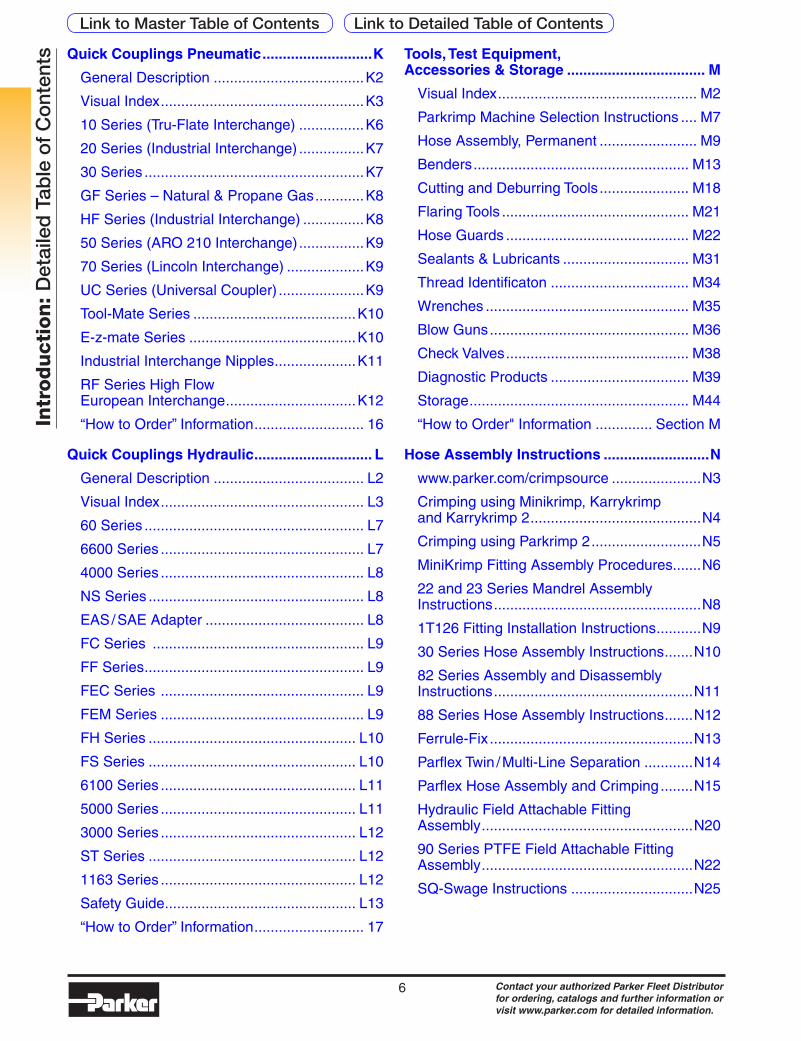
ents Quick Couplings Pneumatic ...........................K
General Description .....................................K2
Visual Index ..................................................K3
10 Series (Tru-Flate Interchange) ................K6
20 Series (Industrial Interchange) ................K7
30 Series ......................................................K7
GF Series – Natural & Propane Gas ............K8
HF Series (Industrial Interchange) ...............K8
50 Series (ARO 210 Interchange) ................K9
70 Series (Lincoln Interchange) ...................K9
UC Series (Universal Coupler) .....................K9
Tool-Mate Series ........................................K10
E-z-mate Series .........................................K10
Industrial Interchange Nipples ....................K11
RF Series High Flow European Interchange ................................K12
“How to Order” Information ........................... 16
Quick Couplings Hydraulic ............................. L
General Description ..................................... L2
Visual Index .................................................. L3
60 Series ...................................................... L7
6600 Series .................................................. L7
4000 Series .................................................. L8
NS Series ..................................................... L8
EAS / SAE Adapter ....................................... L8
FC Series .................................................... L9
FF Series ...................................................... L9
FEC Series .................................................. L9
FEM Series .................................................. L9
FH Series ................................................... L10
FS Series ................................................... L10
6100 Series ................................................ L11
5000 Series ................................................ L11
3000 Series ................................................ L12
ST Series ................................................... L12
1163 Series ................................................ L12
Safety Guide ............................................... L13
“How to Order” Information ........................... 17
Tools, Test Equipment, Accessories & Storage .................................. M
Visual Index ................................................. M2
Parkrimp Machine Selection Instructions .... M7
Hose Assembly, Permanent ........................ M9
Benders ..................................................... M13
Cutting and Deburring Tools ...................... M18
Flaring Tools .............................................. M21
Hose Guards ............................................. M22
Sealants & Lubricants ............................... M31
Thread Identificaton .................................. M34
Wrenches .................................................. M35
Blow Guns ................................................. M36
Check Valves ............................................. M38
Diagnostic Products .................................. M39
Storage ...................................................... M44
“How to Order" Information .............. Section M
Hose Assembly Instructions ..........................N
www.parker.com/crimpsource ......................N3
Crimping using Minikrimp, Karrykrimp and Karrykrimp 2 ..........................................N4
Crimping using Parkrimp 2 ...........................N5
MiniKrimp Fitting Assembly Procedures.......N6
22 and 23 Series Mandrel Assembly Instructions ...................................................N8
1T126 Fitting Installation Instructions ...........N9
30 Series Hose Assembly Instructions .......N10
82 Series Assembly and Disassembly Instructions .................................................N11
88 Series Hose Assembly Instructions .......N12
Ferrule-Fix ..................................................N13
Parflex Twin / Multi-Line Separation ............N14
Parflex Hose Assembly and Crimping ........N15
Hydraulic Field Attachable Fitting Assembly ....................................................N20
90 Series PTFE Field Attachable Fitting Assembly ....................................................N22
SQ-Swage Instructions ..............................N25
Link to Detailed Table of ContentsLink to Master Table of Contents
Contact your authorized Parker Fleet Distributor for ordering, catalogs and further information or visit www.parker.com for detailed information.
7
Intr
od
ucti
on
: D
etai
led
Tab
le o
f C
ont
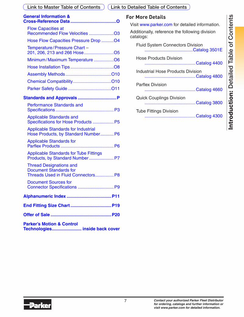
entsGeneral Information &
Cross-Reference Data .....................................O
Flow Capacities at Recommended Flow Velocities ....................O3
Hose Flow Capacities Pressure Drop ..........O4
Temperature / Pressure Chart – 201, 206, 213 and 266 Hose ........................O5
Minimum / Maximum Temperature ................O6
Hose Installation Tips ...................................O8
Assembly Methods .....................................O10
Chemical Compatibility ...............................O10
Parker Safety Guide ...................................O11
Standards and Approvals ...............................P
Performance Standards and Specifications ...............................................P3
Applicable Standards and Specifications for Hose Products .................P5
Applicable Standards for Industrial Hose Products, by Standard Number ...........P6
Applicable Standards for Parflex Products ...........................................P6
Applicable Standards for Tube Fittings Products, by Standard Number ....................P7
Thread Designations and Document Standards for Threads Used in Fluid Connectors ...............P8
Document Sources for Connector Specifications .............................P9
Alphanumeric Index ....................................P11
End Fitting Size Chart .................................P19
Offer of Sale .................................................P20
Parker’s Motion & Control Technologies ........................ inside back cover
For More DetailsVisit www.parker.com for detailed information.
Additionally, reference the following division catalogs:
Fluid System Connectors Division .......................................Catalog 3501E
Hose Products Division .........................................Catalog 4400
Industrial Hose Products Division .........................................Catalog 4800
Parflex Division .........................................Catalog 4660
Quick Couplings Division .........................................Catalog 3800
Tube Fittings Division .........................................Catalog 4300
Link to Detailed Table of ContentsLink to Master Table of Contents
Contact your authorized Parker Fleet Distributor for ordering, catalogs and further information or visit www.parker.com for detailed information.
8
Dimensions and pressures are for reference only and are subject to change.
Intr
od
ucti
on
: O
rder
ing
Info
rmat
ion
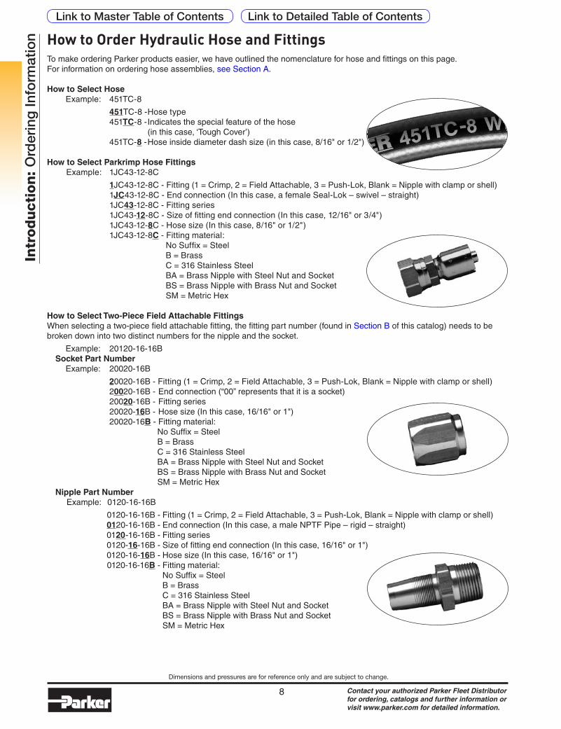
To make ordering Parker products easier, we have outlined the nomenclature for hose and fittings on this page. For information on ordering hose assemblies, see Section A.
How to Select HoseExample: 451TC-8
451TC-8 - Hose type 451TC-8 - Indicates the special feature of the hose (in this case, ‘Tough Cover’) 451TC-8 - Hose inside diameter dash size (in this case, 8/16" or 1/2")
How to Select Parkrimp Hose FittingsExample: 1JC43-12-8C
1JC43-12-8C - Fitting (1 = Crimp, 2 = Field Attachable, 3 = Push-Lok, Blank = Nipple with clamp or shell) 1JC43-12-8C - End connection (In this case, a female Seal-Lok – swivel – straight) 1JC43-12-8C - Fitting series 1JC43-12-8C - Size of fitting end connection (In this case, 12/16" or 3/4") 1JC43-12-8C - Hose size (In this case, 8/16" or 1/2") 1JC43-12-8C - Fitting material: No Suffix = Steel
B = Brass C = 316 Stainless Steel BA = Brass Nipple with Steel Nut and Socket BS = Brass Nipple with Brass Nut and Socket SM = Metric Hex
How to Select Two-Piece Field Attachable FittingsWhen selecting a two-piece field attachable fitting, the fitting part number (found in Section B of this catalog) needs to be broken down into two distinct numbers for the nipple and the socket.
Example: 20120-16-16BSocket Part Number
Example: 20020-16B
20020-16B - Fitting (1 = Crimp, 2 = Field Attachable, 3 = Push-Lok, Blank = Nipple with clamp or shell) 20020-16B - End connection (“00” represents that it is a socket) 20020-16B - Fitting series 20020-16B - Hose size (In this case, 16/16" or 1") 20020-16B - Fitting material:
No Suffix = Steel B = Brass
C = 316 Stainless Steel BA = Brass Nipple with Steel Nut and Socket BS = Brass Nipple with Brass Nut and Socket SM = Metric Hex
Nipple Part NumberExample: 0120-16-16B
0120-16-16B - Fitting (1 = Crimp, 2 = Field Attachable, 3 = Push-Lok, Blank = Nipple with clamp or shell) 0120-16-16B - End connection (In this case, a male NPTF Pipe – rigid – straight) 0120-16-16B - Fitting series 0120-16-16B - Size of fitting end connection (In this case, 16/16" or 1") 0120-16-16B - Hose size (In this case, 16/16" or 1") 0120-16-16B - Fitting material:
No Suffix = Steel B = Brass C = 316 Stainless Steel BA = Brass Nipple with Steel Nut and Socket BS = Brass Nipple with Brass Nut and Socket SM = Metric Hex
How to Order Hydraulic Hose and Fittings
Link to Detailed Table of ContentsLink to Master Table of Contents

Contact your authorized Parker Fleet Distributor for ordering, catalogs and further information or visit www.parker.com for detailed information.
9
Dimensions and pressures are for reference only and are subject to change.
Intr
od
ucti
on
: O
rder
ing
Info
rmat
ion
PrefixSymbol Description
F Parkrimp Crimp Fittings (i.e. 43 Series)
P Parkrimp Crimp Fittings (i.e. 26 Series)
Y Permanent Crimp Fittings (i.e. HY Series)
K Permanent Crimp Fittings (i.e. 81 Series)
PrefixHose Type
Fitting End Configuration
Fitting End Connection Size Hose
SizeFitting
Material
Overall Length (OAL)
Displace-ment Angle
Hose Assembly
Guard1st 2nd 1st 2nd
F 436 06 39 08 08 08 -24
OAL
Parker 436-8
10643-8-8 13943-8-8
How to Order Crimped Hose Assemblies
Hose TypeSymbol Description
436 SAE 100R16 Hose
1st Fitting End ConfigurationSymbol Description
06 Female JIC 37° Swivel Straight
Note: See page 14 for a complete list of fitting configurations.
2nd Fitting End ConfigurationSymbol Description
39 Female JIC 37° Swivel 90° Elbow - Short Drop
Note: See page 14 for a complete list of fitting configurations.
1st Fitting End Connection SizeSymbol Description
08 1/2" Female JIC (3/4x16 thread)
2nd Fitting End Connection SizeSymbol Description
08 1/2" Female JIC (3/4x16 thread)
Hose SizeSymbol Description
08 1/2" Hose ID
Fitting MaterialSymbol Description
No Suffix = Steel
B Brass
C 316 Stainless Steel
BA Brass nipple with steel nut and socket
BS Brass nipple with brass nut and socket
Overall Length (OAL)Symbol Description
24 Expressed in inches (610 mm)
OAL of a hose assembly is measured from the end of the straight fitting or centerline of the fitting seat. OAL of the Seal-Lok™ hose assembly is measured to the sealing surface of the straight fittings or to the centerline of the elbow fittings.
Displacement AngleSymbol Description
270 Specified only if two (2) elbow fittings are used. Starting with either end as the far end, measure angle clockwise to describe the displacement angle of the near end.
Hose Assembly GuardsSymbol Description
SG Spring Guard
AG Armor Guard
HG Polyguard
PG Parkoil
FS Fire Sleeve
AS Partek Sleeving
PS Partek Sleeving
Note: When spelling out an assembly part number list entire sleeving part number
Link to Detailed Table of ContentsLink to Master Table of Contents

Contact your authorized Parker Fleet Distributor for ordering, catalogs and further information or visit www.parker.com for detailed information.
10
Dimensions and pressures are for reference only and are subject to change.
Intr
od
ucti
on
: O
rder
ing
Info
rmat
ion How to Order Field Attachable Hose Assemblies
OAL
Parker 201-6
20120-6-8 23920-6-8
PrefixSymbol Description
R Field Attachable (i.e. 20 Series)
M Mandrel (i.e. 23 Series)
B Clamp (i.e. 88HC-H and 88DB on 88 Series)
C Worm Gear Clamp (i.e. 88H Series on 88 Series)
PrefixHose Type
Fitting End Configuration
Fitting End Connection Size Hose
SizeFitting
Material
Overall Length (OAL)
Displace-ment Angle
Hose Assembly
Guard1st 2nd 1st 2nd
R 201 01 06 06 06 08 -24
Hose TypeSymbol Description
201 SAE 100R5
1st Fitting End ConfigurationSymbol Description
01 Male NPTF Straight
Note: See page 14 for a complete list of fitting configurations.
2nd Fitting End ConfigurationSymbol Description
06 JIC 37° Flare Straight
Note: See page 14 for a complete list of fitting configurations.
1st Fitting End Connection SizeSymbol Description
06 3/8" Pipe Thread
2nd Fitting End Connection SizeSymbol Description
06 3/8" JIC (9/16x18 thread)
Hose SizeSymbol Description
08 13/32" Hose ID
Fitting MaterialSymbol Description
No Suffix = Steel
B Brass
C 316 Stainless Steel
BA Brass nipple with steel nut and socket
BS Brass nipple with brass nut and socket
Overall Length (OAL)Symbol Description
24 Expressed in inches (610 mm)
OAL of a hose assembly is measured from the end of the straight fitting or centerline of the fitting seat. OAL of the Seal-Lok™ hose assembly is measured to the sealing surface of the straight fittings or to the centerline of the elbow fittings.
Displacement AngleSymbol Description
270 Specified only if two (2) elbow fittings are used. Starting with either end as the far end, measure angle clockwise to describe the displacement angle of the near end.
Hose Assembly GuardsSymbol Description
SG Spring Guard
AG Armor Guard
HG Polyguard
PG Parkoil
FS Fire Sleeve
AS Partek Sleeving
PS Partek Sleeving
Note: When spelling out an assembly part number list entire sleeving part number
Link to Detailed Table of ContentsLink to Master Table of Contents
Contact your authorized Parker Fleet Distributor for ordering, catalogs and further information or visit www.parker.com for detailed information.
11
Dimensions and pressures are for reference only and are subject to change.
Intr
od
ucti
on
: O
rder
ing
Info
rmat
ion
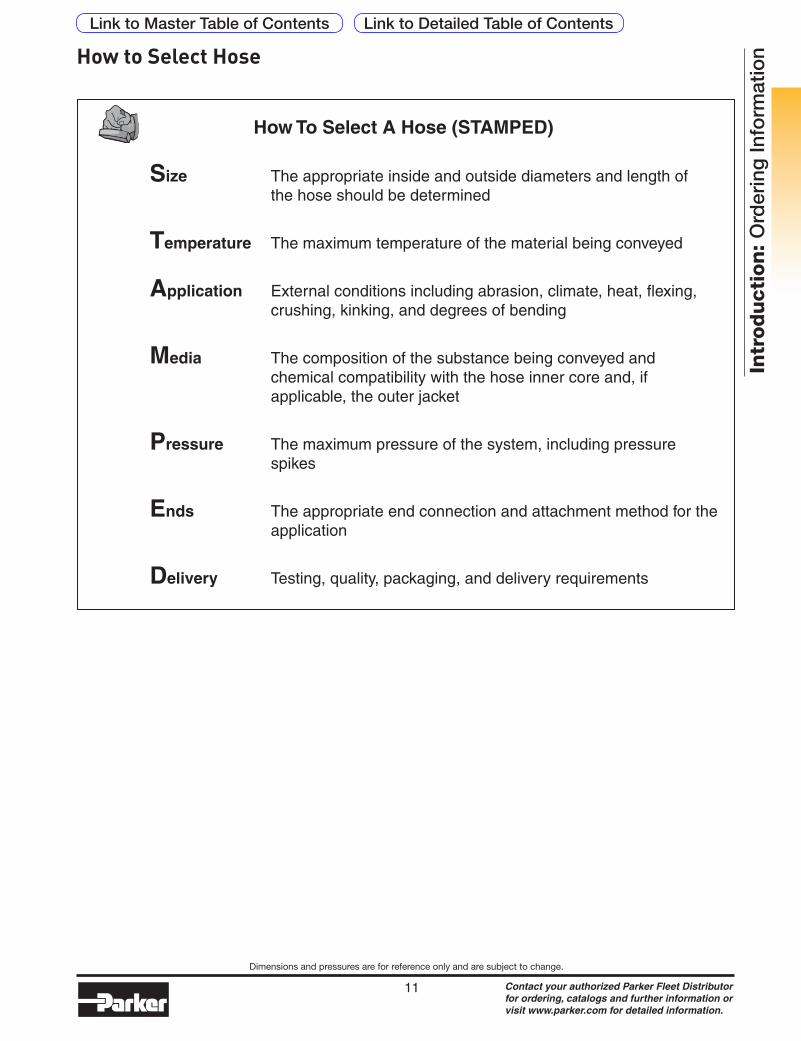
How To Select A Hose (STAMPED)
Size The appropriate inside and outside diameters and length of the hose should be determined
Temperature The maximum temperature of the material being conveyed
Application External conditions including abrasion, climate, heat, flexing, crushing, kinking, and degrees of bending
Media The composition of the substance being conveyed and chemical compatibility with the hose inner core and, if applicable, the outer jacket
Pressure The maximum pressure of the system, including pressure spikes
Ends The appropriate end connection and attachment method for the application
Delivery Testing, quality, packaging, and delivery requirements
How to Select Hose
Link to Detailed Table of ContentsLink to Master Table of Contents
Contact your authorized Parker Fleet Distributor for ordering, catalogs and further information or visit www.parker.com for detailed information.
12
Dimensions and pressures are for reference only and are subject to change.
Intr
od
ucti
on
: O
rder
ing
Info
rmat
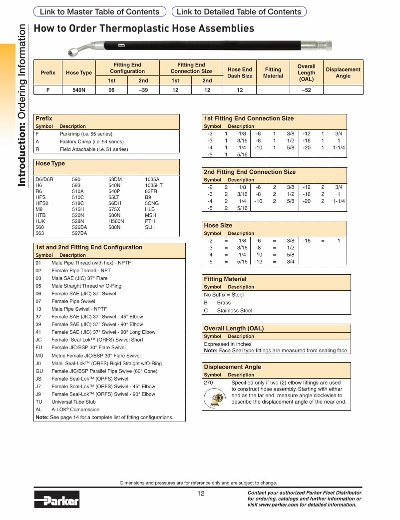
ion How to Order Thermoplastic Hose Assemblies
PrefixSymbol Description
F Parkrimp (i.e. 55 series)
A Factory Crimp (i.e. 54 series)
R Field Attachable (i.e. 51 series)
Prefix Hose TypeFitting End
ConfigurationFitting End
Connection Size Hose End Dash Size
Fitting Material
Overall Length (OAL)
Displacement Angle
1st 2nd 1st 2nd
F 540N 06 –39 12 12 12 –52
Fitting MaterialSymbol Description
No Suffix = Steel
B Brass
C Stainless Steel
Overall Length (OAL)Symbol Description
Expressed in inchesNote: Face Seal type fittings are measured from sealing face.
Hose Type
D6/D6RH6 R6 HFSHFS2M8HTBHJK560563
590593510A510C518C515H520N528N526BA527BA
53DM540N540P55LT56DH575X580NH580N588N
1035A1035HT83FRB95CNGHLBMSHPTHSLH
1st and 2nd Fitting End ConfigurationSymbol Description
01 Male Pipe Thread (with hex) - NPTF
02 Female Pipe Thread - NPT
03 Male SAE (JIC) 37° Flare
05 Male Straight Thread w/ O-Ring
06 Female SAE (JIC) 37° Swivel
07 Female Pipe Swivel
13 Male Pipe Swivel - NPTF
37 Female SAE (JIC) 37° Swivel - 45° Elbow
39 Female SAE (JIC) 37° Swivel - 90° Elbow
41 Female SAE (JIC) 37° Swivel - 90° Long Elbow
JC Female Seal-Lok™ (ORFS) Swivel Short
FU Female JIC/BSP 30° Flare Swivel
MU Metric Female JIC/BSP 30° Flare Swivel
J0 Male Seal-Lok™ (ORFS) Rigid Straight w/O-Ring
GU Female JIC/BSP Parallel Pipe Swive (60° Cone)
JS Female Seal-Lok™ (ORFS) Swivel
J7 Female Seal-Lok™ (ORFS) Swivel - 45° Elbow
J9 Female Seal-Lok™ (ORFS) Swivel - 90° Elbow
TU Universal Tube Stub
AL A-LOK® Compression
Note: See page 14 for a complete list of fitting configurations.
1st Fitting End Connection SizeSymbol Description
-2 1 1/8 -6 1 3/8 -12 1 3/4-3 1 3/16 -8 1 1/2 -16 1 1-4 1 1/4 -10 1 5/8 -20 1 1-1/4-5 1 5/16
2nd Fitting End Connection SizeSymbol Description
-2 2 1/8 -6 2 3/8 -12 2 3/4-3 2 3/16 -8 2 1/2 -16 2 1-4 2 1/4 -10 2 5/8 -20 2 1-1/4-5 2 5/16
Hose SizeSymbol Description
-2 = 1/8 -6 = 3/8 -16 = 1-3 = 3/16 -8 = 1/2-4 = 1/4 -10 = 5/8-5 = 5/16 -12 = 3/4
Displacement AngleSymbol Description
270 Specified only if two (2) elbow fittings are used to construct hose assembly. Starting with either end as the far end, measure angle clockwise to describe the displacement angle of the near end.
Link to Detailed Table of ContentsLink to Master Table of Contents
Contact your authorized Parker Fleet Distributor for ordering, catalogs and further information or visit www.parker.com for detailed information.
13
Dimensions and pressures are for reference only and are subject to change.
Intr
od
ucti
on
: O
rder
ing
Info
rmat
ion
FAREND
270°
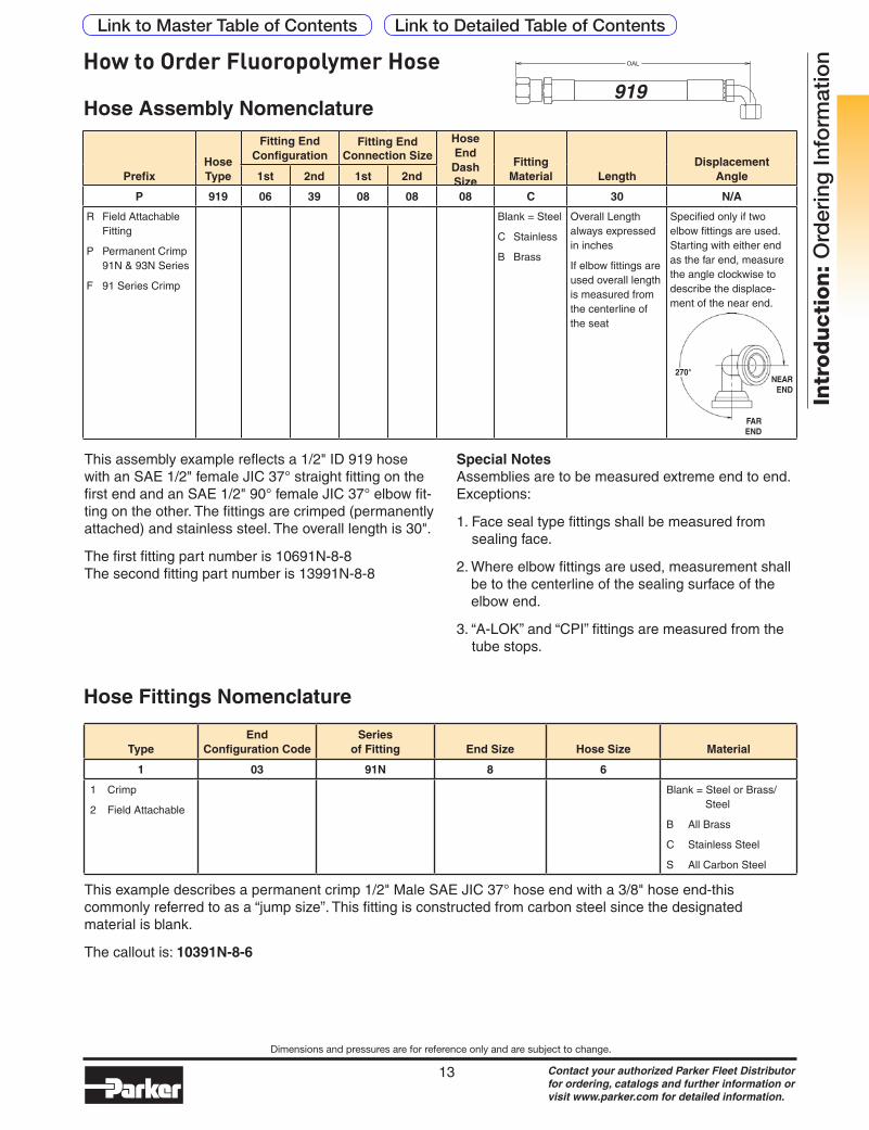
PrefixHose Type
Fitting End Configuration
Fitting End Connection Size
Hose End Dash Size
Fitting Material Length
Displacement Angle1st 2nd 1st 2nd
P 919 06 39 08 08 08 C 30 N/A
R Field Attachable Fitting
P Permanent Crimp 91N & 93N Series
F 91 Series Crimp
Blank = Steel
C Stainless
B Brass
Overall Length always expressed in inches
If elbow fittings are used overall length is measured from the centerline of the seat
Specified only if two elbow fittings are used. Starting with either end as the far end, measure the angle clockwise to describe the displace-ment of the near end.
This assembly example reflects a 1/2" ID 919 hose with an SAE 1/2" female JIC 37° straight fitting on the first end and an SAE 1/2" 90° female JIC 37° elbow fit-ting on the other. The fittings are crimped (permanently attached) and stainless steel. The overall length is 30".
The first fitting part number is 10691N-8-8 The second fitting part number is 13991N-8-8
Special Notes Assemblies are to be measured extreme end to end. Exceptions:
1. Face seal type fittings shall be measured from sealing face.
2. Where elbow fittings are used, measurement shall be to the centerline of the sealing surface of the elbow end.
3. “A-LOK” and “CPI” fittings are measured from the tube stops.
TypeEnd
Configuration CodeSeries
of Fitting End Size Hose Size Material
1 03 91N 8 6
1 Crimp
2 Field Attachable
Blank = Steel or Brass/Steel
B All Brass
C Stainless Steel
S All Carbon Steel
Hose Assembly Nomenclature
Hose Fittings Nomenclature
NEAREND
This example describes a permanent crimp 1/2" Male SAE JIC 37° hose end with a 3/8" hose end-this commonly referred to as a “jump size”. This fitting is constructed from carbon steel since the designated material is blank.
The callout is: 10391N-8-6
How to Order Fluoropolymer Hose
Link to Detailed Table of ContentsLink to Master Table of Contents
Contact your authorized Parker Fleet Distributor for ordering, catalogs and further information or visit www.parker.com for detailed information.
14
Intr
od
ucti
on
: N
ote
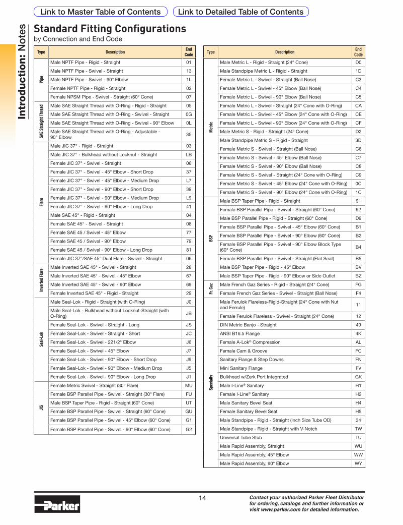
s Standard Fitting Configurationsby Connection and End Code
Type Description End Code
Pipe
Male NPTF Pipe - Rigid - Straight 01
Male NPTF Pipe - Swivel - Straight 13
Male NPTF Pipe - Swivel - 90° Elbow 1L
Female NPTF Pipe - Rigid - Straight 02
Female NPSM Pipe - Swivel - Straight (60° Cone) 07
SAE
Stra
ight
Thr
ead Male SAE Straight Thread with O-Ring - Rigid - Straight 05
Male SAE Straight Thread with O-Ring - Swivel - Straight 0G
Male SAE Straight Thread with O-Ring - Swivel - 90° Elbow 0L
Male SAE Straight Thread with O-Ring - Adjustable - 90° Elbow
35
Flar
e
Male JIC 37° - Rigid - Straight 03
Male JIC 37° - Bulkhead without Locknut - Straight LB
Female JIC 37° - Swivel - Straight 06
Female JIC 37° - Swivel - 45° Elbow - Short Drop 37
Female JIC 37° - Swivel - 45° Elbow - Medium Drop L7
Female JIC 37° - Swivel - 90° Elbow - Short Drop 39
Female JIC 37° - Swivel - 90° Elbow - Medium Drop L9
Female JIC 37° - Swivel - 90° Elbow - Long Drop 41
Male SAE 45° - Rigid - Straight 04
Female SAE 45° - Swivel - Straight 08
Female SAE 45 / Swivel - 45° Elbow 77
Female SAE 45 / Swivel - 90° Elbow 79
Female SAE 45 / Swivel - 90° Elbow - Long Drop 81
Female JIC 37°/SAE 45° Dual Flare - Swivel - Straight 06
Inve
rted
Flar
e Male Inverted SAE 45° - Swivel - Straight 28
Male Inverted SAE 45° - Swivel - 45° Elbow 67
Male Inverted SAE 45° - Swivel - 90° Elbow 69
Female Inverted SAE 45° - Rigid - Straight 29
Seal
-Lok
Male Seal-Lok - Rigid - Straight (with O-Ring) J0
Male Seal-Lok - Bulkhead without Locknut-Straight (with O-Ring)
JB
Female Seal-Lok - Swivel - Straight - Long JS
Female Seal-Lok - Swivel - Straight - Short JC
Female Seal-Lok - Swivel - 221/2° Elbow J6
Female Seal-Lok - Swivel - 45° Elbow J7
Female Seal-Lok - Swivel - 90° Elbow - Short Drop J9
Female Seal-Lok - Swivel - 90° Elbow - Medium Drop J5
Female Seal-Lok - Swivel - 90° Elbow - Long Drop J1
JIS
Female Metric Swivel - Straight (30° Flare) MU
Female BSP Parallel Pipe - Swivel - Straight (30° Flare) FU
Male BSP Taper Pipe - Rigid - Straight (60° Cone) UT
Female BSP Parallel Pipe - Swivel - Straight (60° Cone) GU
Female BSP Parallel Pipe - Swivel - 45° Elbow (60° Cone) G1
Female BSP Parallel Pipe - Swivel - 90° Elbow (60° Cone) G2
Type Description End Code
Met
ric
Male Metric L - Rigid - Straight (24° Cone) D0
Male Standpipe Metric L - Rigid - Straight 1D
Female Metric L - Swivel - Straight (Ball Nose) C3
Female Metric L - Swivel - 45° Elbow (Ball Nose) C4
Female Metric L - Swivel - 90° Elbow (Ball Nose) C5
Female Metric L - Swivel - Straight (24° Cone with O-Ring) CA
Female Metric L - Swivel - 45° Elbow (24° Cone with O-Ring) CE
Female Metric L - Swivel - 90° Elbow (24° Cone with O-Ring) CF
Male Metric S - Rigid - Straight (24° Cone) D2
Male Standpipe Metric S - Rigid - Straight 3D
Female Metric S - Swivel - Straight (Ball Nose) C6
Female Metric S - Swivel - 45° Elbow (Ball Nose) C7
Female Metric S - Swivel - 90° Elbow (Ball Nose) C8
Female Metric S - Swivel - Straight (24° Cone with O-Ring) C9
Female Metric S - Swivel - 45° Elbow (24° Cone with O-Ring) 0C
Female Metric S - Swivel - 90° Elbow (24° Cone with O-Ring) 1C
BSP
Male BSP Taper Pipe - Rigid - Straight 91
Female BSP Parallel Pipe - Swivel - Straight (60° Cone) 92
Male BSP Parallel Pipe - Rigid - Straight (60° Cone) D9
Female BSP Parallel Pipe - Swivel - 45° Elbow (60° Cone) B1
Female BSP Parallel Pipe - Swivel - 90° Elbow (60° Cone) B2
Female BSP Parallel Pipe - Swivel - 90° Elbow Block Type (60° Cone)
B4
Female BSP Parallel Pipe - Swivel - Straight (Flat Seat) B5
Male BSP Taper Pipe - Rigid - 45° Elbow BV
Male BSP Taper Pipe - Rigid - 90° Elbow or Side Outlet BZ
Fr. G
az Male French Gaz Series - Rigid - Straight (24° Cone) FG
Female French Gaz Series - Swivel - Straight (Ball Nose) F4
Spec
ialty
Male Ferulok Flareless-Rigid-Straight (24° Cone with Nut and Ferrule)
11
Female Ferulok Flareless - Swivel - Straight (24° Cone) 12
DIN Metric Banjo - Straight 49
ANSI B16.5 Flange 4K
Female A-Lok® Compression AL
Female Cam & Groove FC
Sanitary Flange & Step Downs FN
Mini Sanitary Flange FV
Bulkhead w/Zerk Port Integrated GK
Male I-Line® Sanitary H1
Female I-Line® Sanitary H2
Male Sanitary Bevel Seat H4
Female Sanitary Bevel Seat H5
Male Standpipe - Rigid - Straight (Inch Size Tube OD) 34
Male Standpipe - Rigid - Straight with V-Notch TW
Universal Tube Stub TU
Male Rapid Assembly, Straight WU
Male Rapid Assembly, 45° Elbow WW
Male Rapid Assembly, 90° Elbow WY
Link to Detailed Table of ContentsLink to Master Table of Contents
Contact your authorized Parker Fleet Distributor for ordering, catalogs and further information or visit www.parker.com for detailed information.
15
Dimensions and pressures are for reference only and are subject to change.
Intr
od
ucti
on
: O
rder
ing
Info
rmat
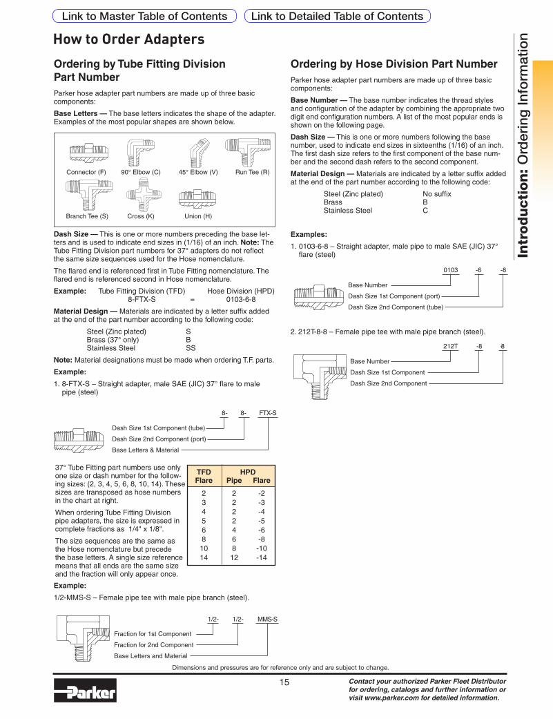
ionHow to Order Adapters
Dash Size — This is one or more numbers preceding the base let-ters and is used to indicate end sizes in (1/16) of an inch. Note: The Tube Fitting Division part numbers for 37° adapters do not reflect the same size sequences used for the Hose nomenclature.
The flared end is referenced first in Tube Fitting nomenclature. The flared end is referenced second in Hose nomenclature.
Example: Tube Fitting Division (TFD) Hose Division (HPD) 8-FTX-S = 0103-6-8
Material Design — Materials are indicated by a letter suffix added at the end of the part number according to the following code:
Steel (Zinc plated) S Brass (37° only) B Stainless Steel SS
Note: Material designations must be made when ordering T.F. parts.
Example:
1. 8-FTX-S – Straight adapter, male SAE (JIC) 37° flare to male pipe (steel)
Ordering by Tube Fitting Division Part NumberParker hose adapter part numbers are made up of three basic components:
Base Letters — The base letters indicates the shape of the adapter. Examples of the most popular shapes are shown below.
Connector (F) 90° Elbow (C) 45° Elbow (V) Run Tee (R)
Branch Tee (S) Cross (K) Union (H)
Dash Size 1st Component (tube)
Dash Size 2nd Component (port)
Base Letters & Material
37° Tube Fitting part numbers use only one size or dash number for the follow-ing sizes: (2, 3, 4, 5, 6, 8, 10, 14). These sizes are transposed as hose numbers in the chart at right.
When ordering Tube Fitting Division pipe adapters, the size is expressed in complete fractions as 1/4" x 1/8".
The size sequences are the same as the Hose nomenclature but precede the base letters. A single size reference means that all ends are the same size and the fraction will only appear once.
TFD HPD Flare Pipe Flare
2 2 -2 3 2 -3 4 2 -4 5 2 -5 6 4 -6 8 6 -8 10 8 -10 14 12 -14
Fraction for 1st Component
Fraction for 2nd Component
Base Letters and Material
1/2- 1/2- MMS-S
Example:
1/2-MMS-S – Female pipe tee with male pipe branch (steel).
0103 -6 -8
Base Number
Dash Size 1st Component (port)
Dash Size 2nd Component (tube)
Ordering by Hose Division Part NumberParker hose adapter part numbers are made up of three basic components:
Base Number — The base number indicates the thread styles and configuration of the adapter by combining the appropriate two digit end configuration numbers. A list of the most popular ends is shown on the following page.
Dash Size — This is one or more numbers following the base number, used to indicate end sizes in sixteenths (1/16) of an inch. The first dash size refers to the first component of the base num-ber and the second dash refers to the second component.
Material Design — Materials are indicated by a letter suffix added at the end of the part number according to the following code:
Steel (Zinc plated) No suffix Brass B Stainless Steel C
Examples:
1. 0103-6-8 – Straight adapter, male pipe to male SAE (JIC) 37° flare (steel)
2. 212T-8-8 – Female pipe tee with male pipe branch (steel).
212T -8 -8
Base Number
Dash Size 1st Component
Dash Size 2nd Component
8- 8- FTX-S
Link to Detailed Table of ContentsLink to Master Table of Contents

Contact your authorized Parker Fleet Distributor for ordering, catalogs and further information or visit www.parker.com for detailed information.
16
Dimensions and pressures are for reference only and are subject to change.
Intr
od
ucti
on
: O
rder
ing
Info
rmat
ion
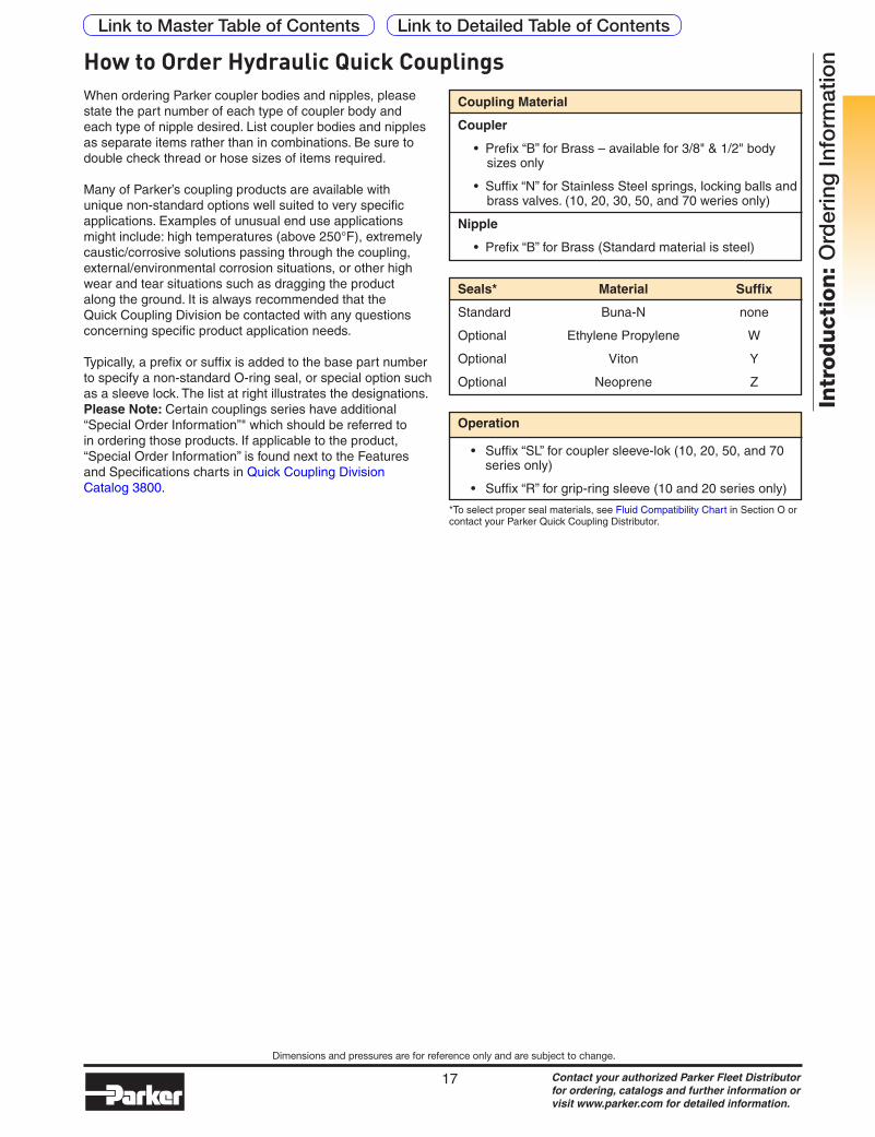
When ordering Parker coupler bodies and nipples, please state the part number of each type of coupler body and each type of nipple desired. List coupler bodies and nipples as separate items rather than in combinations. Be sure to double check thread or hose sizes of items required.
Many of Parker’s coupling products are available with unique non-standard options well suited to very specific applications. Examples of unusual end use applications might include: high temperatures (above 250°F), extremely caustic/corrosive solutions passing through the coupling, external/environmental corrosion situations, or other high wear and tear situations such as dragging the product along the ground. It is always recommended that the Quick Coupling Division be contacted with any questions concerning specific product application needs.
Typically, a prefix or suffix is added to the base part number to specify a non-standard O-ring seal, or special option such as a sleeve lock. The list at right illustrates the designations.Please Note: Certain couplings series have additional “Special Order Information” which should be referred to in ordering those products. If applicable to the product, “Special Order Information” is found next to the Features and Specifications charts in Quick Coupling Division Catalog 3800.
Seals* Material Suffix
Standard Buna-N noneOptional Ethylene Propylene WOptional Viton YOptional Neoprene Z
• Suffix “SL” for coupler sleeve-lok (10, 20, 50, and 70 series only)
• Suffix “R” for grip-ring sleeve (10, 20, 50, and 70 series only)
Operation
Coupling Material
Coupler
• Prefix “B” for Brass - available for 3/8 & 1/2” body sizes only
• Suffix “N” for Stainless Steel springs, locking balls and brass valves. (10, 20, 30, 50, and 70 series only)
Nipple
• Prefix “B” for Brass (Standard material is stainless steel)
*To help select proper materials, contact your Parker Quick Coupling Distributor.
How to Order Pneumatic Quick Couplings
Checklist for Selecting Quick Couplings
❑ What are the functional requirements of the coupling?
❑ What is the maximum working pressure of the application?
❑ Which seals and body material are compatible with the system’s fluid?
❑ Is the application static or dynamic?
❑ What size coupler is required?
❑ What is the maximum pressure drop suitable for the application?
❑ Does the application require the ability to connect and disconnect under pressure?
❑ What is the media temperature and ambient temperature?
❑ What end configurations are required?
❑ Is an industry interchange coupler required?
❑ Is air inclusion and fluid loss a concern in the application?
Link to Detailed Table of ContentsLink to Master Table of Contents
Contact your authorized Parker Fleet Distributor for ordering, catalogs and further information or visit www.parker.com for detailed information.
17
Dimensions and pressures are for reference only and are subject to change.
Intr
od
ucti
on
: O
rder
ing
Info
rmat
ion
Coupling Material
Coupler
• Prefix “B” for Brass – available for 3/8" & 1/2" body sizes only
• Suffix “N” for Stainless Steel springs, locking balls and brass valves. (10, 20, 30, 50, and 70 weries only)
Nipple
• Prefix “B” for Brass (Standard material is steel)
When ordering Parker coupler bodies and nipples, please state the part number of each type of coupler body and each type of nipple desired. List coupler bodies and nipples as separate items rather than in combinations. Be sure to double check thread or hose sizes of items required.
Many of Parker’s coupling products are available with unique non-standard options well suited to very specific applications. Examples of unusual end use applications might include: high temperatures (above 250°F), extremely caustic/corrosive solutions passing through the coupling, external/environmental corrosion situations, or other high wear and tear situations such as dragging the product along the ground. It is always recommended that the Quick Coupling Division be contacted with any questions concerning specific product application needs.
Typically, a prefix or suffix is added to the base part number to specify a non-standard O-ring seal, or special option such as a sleeve lock. The list at right illustrates the designations. Please Note: Certain couplings series have additional “Special Order Information”" which should be referred to in ordering those products. If applicable to the product, “Special Order Information” is found next to the Features and Specifications charts in Quick Coupling Division Catalog 3800.
How to Order Hydraulic Quick Couplings
Seals* Material Suffix
Standard Buna-N none
Optional Ethylene Propylene W
Optional Viton Y
Optional Neoprene Z
Operation
• Suffix “SL” for coupler sleeve-lok (10, 20, 50, and 70 series only)
• Suffix “R” for grip-ring sleeve (10 and 20 series only)
*To select proper seal materials, see Fluid Compatibility Chart in Section O or contact your Parker Quick Coupling Distributor.
Link to Detailed Table of ContentsLink to Master Table of Contents
Contact your authorized Parker Fleet Distributor for ordering, catalogs and further information or visit www.parker.com for detailed information.
18
Dimensions and pressures are for reference only and are subject to change.
Intr
od
ucti
on
: O
rder
ing
Info
rmat
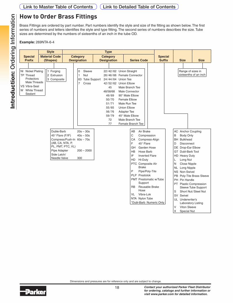
ion How to Order Brass Fittings
Brass Fittings are ordered by part number. Part numbers identify the style and size of the fitting as shown below. The first series of numbers and letters identifies the style and type fitting. The second series of numbers describes the size. Tube sizes are determined by the numbers of sixteenths of an inch in the tube OD.
Example: 269NTA-6-4
Special Prefix
Style Type
Special Suffix Size Size
Material Code (Shapes)
Category Designation
Category Designation Series Code
Duble-Barb 20s – 30s45° Flare (F/IF) 40s – 50sCompress/Push-In 60s – 70s (AB, CA, NTA, P, PL, PMT, PTC, VL)Pipe Adapter 200 – 2000Side Latch/ Needle Valve 300
1 Forging2 Extrusion3 Composite
NI Nickel PlatingTP Thread
Protectors Male Threads
VS Vibra-SealW White Thread
Sealant
AC Anchor CouplingB Body OnlyBH BulkheadD DisconnectDE Drop-Ear ElbowGT Dubl-Barb ToolHD Heavy DutyL Long NutN Close NippleNL Long NippleNS Non-SwivelPB Poly-Tite Brass SleevePH Pin HandlePT Plastic Compression
Sleeve Tube SupportS Short Nut / Steel NutSV SwivelUL Underwriter’s
Laboratory ListingV Viton SleeveX Special Nut
AB Air BrakeC CompressionCA Compress-AlignF 45° FlareGH Garden HoseHB Hose BarbIF Inverted FlareHD Hi-DutyPTC Composite AIr
BrakeP Pipe/Poly-TitePLP PrestolokPMT Prestomatic w/Tube
SupportRB Reusable Brake
HoseVL Vibra-LokNTA Nylon Tube*Dubl-Barb Numeric Only
0 Sleeve1 Nut63 Tube Support7 Cross
22 / 42 / 62 Union Straight 26 / 46 / 66 Female Connector 24 / 44 / 64 Union Tee 42 / 52 / 62 Union Elbow 45 Male Branch Tee48/58/68 Male Connector 49 / 69 90° Male Elbow 50 / 70 Female Elbow 51 / 71 Male Run Tee 55 / 65 Union Elbow 56 / 76 Adapter Tee 59 / 79 45° Male Elbow 72 Male Branch Tee 77 Female Branch Tee
Range of sizes in sixteenths of an inch
Link to Detailed Table of ContentsLink to Master Table of Contents