Flame Spraying of Aluminum Coatings Reinforced with ...
18
materials Article Flame Spraying of Aluminum Coatings Reinforced with Particles of Carbonaceous Materials as an Alternative for Laser Cladding Technologies Artur Czupry ´ nski Welding Department, Faculty of Mechanical Engineering, Silesian University of Technology, ul. Konarskiego 18A, 44-100 Gliwice, Poland; [email protected] Received: 20 September 2019; Accepted: 20 October 2019; Published: 23 October 2019 Abstract: The article presents results of the preliminary research of mechanical properties of flame-sprayed aluminum coatings reinforced with carbon materials made on the construction steel S235J0 substrate. For reinforcement the following carbon materials were used: carbon nanotubes Nanocyl NC 7000 (0.5 wt.% and 1 wt.%) and carburite (0.5 wt.%). The properties evaluation was made using metallographic macroscope and microscope, chemical composition, microhardness, abrasion and erosion resistance studies. The obtained results were compared with aluminum powder coatings (EN AW 1000 series). It was proved that the flame spraying of aluminum coatings reinforced with particles of carbonaceous materials can be an effective alternative for laser cladding technology. The preliminary test results will be successively extended by further experiments to contribute in the near future to develop innovative technologies, that can be implemented in the automotive industry for production of components with high strength, wear resistance, good thermal conductivity and low density, such as brake shoes, cylinder liners, piston rings and gears. Keywords: flame powder spray process; coating; aluminum; carbon nanotubes; carburite; abrasive wear resistance; erosion wear resistance 1. Introduction Modern civilization expects from material engineering scientists to produce lightweight and durable materials that meet the high strength and quality requirements set for innovative constructions made by the automotive and aerospace industries. Under certain structural load conditions, the increase of strength and stiffness of the materials contributes to reducing construction dimensions and consequently also the mass. Because the global oil resources are constantly declining, and renewable energy sources are not effective enough yet, use of lightweight and durable materials becomes a necessity. This type of materials is highly desirable in car, aircraft and space vehicle production because its use has many benefits, such as lower fuel consumption, higher capacity and speed. Insufficient strength and stiffness of the constructions made of metals and alloys led to the development of metal-matrix composites (MMC). The composites of this type achieve high strength and ductility thanks to the metallic matrix, while the stiffness is provided by the reinforcement, which consists of particles-perchance fibers-metallic or ceramic with high stiffness. The microstructure of this materials consists of soft matrix and hard phases which provides increase in abrasion resistance also at high temperatures. Metal-matrix composites can be designed to have specific properties, such as low thermal expansion coefficient and high thermal conductivity so that these materials are suitable for use in applications for installation of electronic microcircuits. Metal-matrix composite materials are widely used in car and air applications nowadays [1–3]. In the 1970s, technologies for producing high-strength carbon fibers were developed. They began to be used for the preparation of advanced composites used for producing rocket engine nozzles, Materials 2019, 12, 3467; doi:10.3390/ma12213467 www.mdpi.com/journal/materials
Transcript of Flame Spraying of Aluminum Coatings Reinforced with ...

materials
Article
Flame Spraying of Aluminum Coatings Reinforcedwith Particles of Carbonaceous Materials as anAlternative for Laser Cladding Technologies
Artur CzuprynskiWelding Department, Faculty of Mechanical Engineering, Silesian University of Technology, ul.Konarskiego 18A, 44-100 Gliwice, Poland; [email protected]
Received: 20 September 2019; Accepted: 20 October 2019; Published: 23 October 2019�����������������
Abstract: The article presents results of the preliminary research of mechanical properties offlame-sprayed aluminum coatings reinforced with carbon materials made on the construction steelS235J0 substrate. For reinforcement the following carbon materials were used: carbon nanotubesNanocyl NC 7000 (0.5 wt.% and 1 wt.%) and carburite (0.5 wt.%). The properties evaluation was madeusing metallographic macroscope and microscope, chemical composition, microhardness, abrasionand erosion resistance studies. The obtained results were compared with aluminum powder coatings(EN AW 1000 series). It was proved that the flame spraying of aluminum coatings reinforced withparticles of carbonaceous materials can be an effective alternative for laser cladding technology.The preliminary test results will be successively extended by further experiments to contribute in thenear future to develop innovative technologies, that can be implemented in the automotive industryfor production of components with high strength, wear resistance, good thermal conductivity andlow density, such as brake shoes, cylinder liners, piston rings and gears.
Keywords: flame powder spray process; coating; aluminum; carbon nanotubes; carburite; abrasivewear resistance; erosion wear resistance
1. Introduction
Modern civilization expects from material engineering scientists to produce lightweight anddurable materials that meet the high strength and quality requirements set for innovative constructionsmade by the automotive and aerospace industries. Under certain structural load conditions, theincrease of strength and stiffness of the materials contributes to reducing construction dimensions andconsequently also the mass. Because the global oil resources are constantly declining, and renewableenergy sources are not effective enough yet, use of lightweight and durable materials becomes anecessity. This type of materials is highly desirable in car, aircraft and space vehicle production becauseits use has many benefits, such as lower fuel consumption, higher capacity and speed. Insufficientstrength and stiffness of the constructions made of metals and alloys led to the development ofmetal-matrix composites (MMC). The composites of this type achieve high strength and ductilitythanks to the metallic matrix, while the stiffness is provided by the reinforcement, which consists ofparticles-perchance fibers-metallic or ceramic with high stiffness. The microstructure of this materialsconsists of soft matrix and hard phases which provides increase in abrasion resistance also at hightemperatures. Metal-matrix composites can be designed to have specific properties, such as lowthermal expansion coefficient and high thermal conductivity so that these materials are suitable for usein applications for installation of electronic microcircuits. Metal-matrix composite materials are widelyused in car and air applications nowadays [1–3].
In the 1970s, technologies for producing high-strength carbon fibers were developed. They beganto be used for the preparation of advanced composites used for producing rocket engine nozzles,
Materials 2019, 12, 3467; doi:10.3390/ma12213467 www.mdpi.com/journal/materials

Materials 2019, 12, 3467 2 of 18
projectile cores, thermal shields, isolators and thermal radiators. Since 1970, carbon fibre reinforcedcomposites have been widely used in the production of aircraft brakes, space constructions, militaryand commercial airplanes, lithium-ion batteries and sports equipment. Research in the field of carbonmaterials has been revolutionized by the discovery of carbon nanotubes (CNT) by Sumio Iijima in1991. The carbon nanotubes (CNTs) have unique mechanical properties compared to carbon fibers, e.g.stiffness to 1000 GPa, strength of 100 GPa and thermal conductivity to 6000 W/(m·K) [4,5]. In recentyears, a number of studies have been carried out using CNT carbon nanotubes as reinforcement ofvarious materials: polymers, ceramics and metals, with the majority of research involving polymercomposites [6,7], ceramic composites in second place [8,9], and only recently have been publishedseveral papers on composites with metallic matrix reinforced with carbon nanotubes (CNT) [10,11].This is quite surprising considering the fact that most construction materials used in the contemporaryworld are metals. Publications on this topic concern various aspects such as fabrication [12–15],microstructure [16,17], modelling of mechanical properties and the chemical interaction betweencarbon nanotubes (CNTs) and metals [4,18–21]
Nanotechnology had a strong influence on the direction of research in the field of surfaceengineering and related production technology of surface layers and coatings [22,23]. Nowadays, it ispossible to use welding methods for producing not only conventional tribological coatings with specificfrictional characteristics (high or low coefficient of friction) and resistance to wear, erosion or corrosionbut also for producing coatings with unprecedented properties, often intended for special applicationsand working in difficult conditions, e.g., nanocomposite coatings with high hardness and highresistance to dynamic loads, coatings with frictional characteristics that adapt to changing operatingconditions (temperature, humidity), thermal barrier coatings or biocompatible coatings [24,25]. Often,high-quality nanostructure coatings are used on parts of car engines made of aluminum alloys, oncopper alloys intended for propellers of vessels, or on heat-resistant intermetals. In surface engineeringtechnology, the implementation of this type of coating is possible by thermal spraying, where theapplied metallic layer is bonded to the substrate adhesively or mechanically without melting the basematerial [24]. The main advantage of thermal spraying technology is a minimal thermal influence onthe sprayed materials. Even in the case of laser cladding technologies characterized by the lowest heatinput of all the cladding technologies, the substrate material is always partially melted, as well asthe additional material, usually in a form of metallic or composite powder. The carbon nanotubes,due to the small dimensions, have very low heat capacity. Additionally, they have high absorption oflaser radiation. For this reason, the introduction of carbon nanotubes into the melt pool during lasercladding is basically impossible, because overheating and decomposition of nanotubes [26–33].
Pioneers in the field of thermal spraying processes for composite coatings of aluminum-carbonnanotubes (CNT) were a research group from Florida International University, who successfullydeposited carbon nanotubes in the Al-Si matrix in the powder plasma spraying process [34].
S. R. Bakshi and others [10] made multi-layer nanocomposite coatings of aluminum-carbonnanotubes (CNT) in the cold gas spraying process. In order to obtain a good dispersion of carbonnanotubes in Al-Si microparticle eutectic powders, spray drying was used. Spray-dried powderscontaining 5 wt.% carbon nanotubes (CNTs) were mixed with pure aluminum powder to obtain totalnominal carbon nanotube (CNT) compositions in the coating material of 0.5 wt.% and 1 wt.%. Asa result of cold spraying, coatings with a thickness of 500 µm were obtained in which the carbonnanotubes were evenly distributed in the matrix. The carbon nanotubes were of shorter length becauseduring the deposition process they fractured as a result of impact and shear between the Al-Si particlesand the aluminum matrix.
A. K. Keshri and others [11] compared impact on carbon nanotubes (CNTs) of various heat sourcesused during thermal spray processes—plasma spraying (PS), high-velocity oxy fuel spraying (HVOF),cold spraying (CS) and plasma spraying of liquid precursor (PSLP). Carbon nanotubes (CNTs) havebeen successfully preserved as reinforcements in composite metal and ceramic coatings in all thermalspray processes with the exception of PSLP.
Materials 2019, 12, 3467 3 of 18
There is no data in the literature regarding tribological properties of powder flame-sprayed (PFS)aluminum coatings reinforced with carbon nanotubes (CNT). The purpose of this article is to presentthe state of knowledge in this area of research and present the possibility of using powder flame spraytechnology (PFS) for the production of composite coatings with a metallic matrix reinforced withcarbon nanotubes (CNT).
2. Materials and Methods
2.1. Aim of Study
The conducted studies were aimed at comparing the structure, chemical composition, hardnessand resistance to abrasive and erosive wear of powder aluminum flame-sprayed coatings reinforcedwith Nanocyl NC 7000 carbon nanotubes in amount of 0.5 wt.%, 1 wt.% and carburite in an amountof 0.5 wt.% with a reference coating made of aluminum powder EN AW 1000 series (MetallisationLtd., West Midlands, UK) on non-alloy S235J0 steel. Carburite as aluminum matrix reinforcement wasused in order to compare tribological properties of this composite coating with coating reinforced withCNTs with equal weight participation of carbon material. The scope of research included:
• Preparation of material for spraying;• Selection process parameters for each of the coating based on preliminary technological tests;• Coating manufacturing;• Examining the structure and tribological properties of aluminum coatings reinforced with carbon
nanotubes and carburite;• Comparison of obtained samples with coatings made of aluminum powder without the addition
of carbonaceous materials.
2.2. Materials, Devices and Spraying Parameters
The additional material for flame-spraying was obtained by mixing in the ball mill appropriateproportions of aluminum powder (EN AW 1000 series) with carbon nanotubes and aluminum powder inthe form of filter dust carburite (Table 1). Carbon nanotubes that were used in the test are commerciallyavailable multi-walled carbon nanotubes MWCNTs, produced in the Catalytic Chemical VaporDeposition (CCVD) process, NANOCYLTM NC7000 (Belgium Nanocyl SA, Sambreville, Belgium)(Table 2).
Table 1. Specification of aluminum powder EN AW 1000 series.
Specification Unit Guaranteed Parameters Obtained Results
Aluminum content (Al) % min 99.7 99.7Iron content (Fe) % max 0.2 0.2
Silicon content (Si) % max 0.12 0.12Copper content (Cu) % max 0.004 0.004
Moisture % max 0.1 0.1Bulk density g/dm3 min 1000 1050
Granulation above 0.045 mm % 85.0−100.0 98.0Granulation above 0.1 mm % 5.0−30.0 15.3
Granulation above 0.16 mm % max 5.0 0.0

Materials 2019, 12, 3467 4 of 18
Table 2. Structure and specification of Nanocyl NC 7000 carbon nanotubes and of filter dust carburite.Materials 2019, 12, x FOR PEER REVIEW 4 of 18
Structure of Nanocyl NC 7000 carbon nanotubes
Properties Unit Value Measurement Method
Average diameter Nanometer 9.5 TEM
Average length Micrometer 1.5 TEM
Carbon purity % 90 TGA
Metal oxide % 10 TGA
Amorphous carbon - 1) HRTEM
Surface area m2/g 250–300 BET
Note: 1) pyrolytically deposited carbon on the surface of the NC 7000.
Structure of filter dust carburite
Properties Unit Value
Fraction size Millimeter >0 up to 1
Dust content % 5
Moisture content % 1
Carburite content % 94
Granulation [mm] % >1 mm up to 10%; <0,06 mm up to 70%
The subsonic flame spraying process was carried out cold in accordance with the standard EN
13507:2018 [35] on workstation, equipped with hand-guided modern oxyacetylene system (CastoDyn
DS 8000 (Messer Eutectic Castolin, Gliwice, Poland). Final surface preparation was done by shot
blasting sheets prior to spraying with sharp-edged cast iron of 0.5–1.5 mm shot grain size in
accordance with standard ISO 2063-1:2017 [36]. Final surface roughness of the steel substrate after
shot blasting was Ra = 12 μm, Rz = 85 μm. Before the spraying process, steel plates with dimensions
of 150 × 150 × 5 mm3 were preheated with a gas burner up to a temperature of 40 °C (the temperature
of preheating was measured using pyrometer). The standard modular nozzles regulating the flame
outlet SSM 40 (Messer Eutectic Castolin, Gliwice, Poland) and the neutral flame (ratio O2/C2H2 = 1,2)
were used. This allowed to obtain the proper spray jet [37,38]. The flame jet burner was guided in a
horizontal position covering the whole surface of the sheet. During the process the spraying direction
was changed several times by 90°, until obtained thickness of coating was about 1,0 mm. Distance
between the torch and the sprayed surface was 200 mm. The parameters and flame type were
constant for each test (Figure 1).
Structure of Nanocyl NC 7000 carbon nanotubes
Properties Unit Value Measurement Method
Average diameter Nanometer 9.5 TEMAverage length Micrometer 1.5 TEMCarbon purity % 90 TGA
Metal oxide % 10 TGAAmorphous carbon - 1) HRTEM
Surface area m2/g 250–300 BET
Note: 1) pyrolytically deposited carbon on the surface of the NC 7000.
Materials 2019, 12, x FOR PEER REVIEW 4 of 18
Structure of Nanocyl NC 7000 carbon nanotubes
Properties Unit Value Measurement Method
Average diameter Nanometer 9.5 TEM
Average length Micrometer 1.5 TEM
Carbon purity % 90 TGA
Metal oxide % 10 TGA
Amorphous carbon - 1) HRTEM
Surface area m2/g 250–300 BET
Note: 1) pyrolytically deposited carbon on the surface of the NC 7000.
Structure of filter dust carburite
Properties Unit Value
Fraction size Millimeter >0 up to 1
Dust content % 5
Moisture content % 1
Carburite content % 94
Granulation [mm] % >1 mm up to 10%; <0,06 mm up to 70%
The subsonic flame spraying process was carried out cold in accordance with the standard EN
13507:2018 [35] on workstation, equipped with hand-guided modern oxyacetylene system (CastoDyn
DS 8000 (Messer Eutectic Castolin, Gliwice, Poland). Final surface preparation was done by shot
blasting sheets prior to spraying with sharp-edged cast iron of 0.5–1.5 mm shot grain size in
accordance with standard ISO 2063-1:2017 [36]. Final surface roughness of the steel substrate after
shot blasting was Ra = 12 μm, Rz = 85 μm. Before the spraying process, steel plates with dimensions
of 150 × 150 × 5 mm3 were preheated with a gas burner up to a temperature of 40 °C (the temperature
of preheating was measured using pyrometer). The standard modular nozzles regulating the flame
outlet SSM 40 (Messer Eutectic Castolin, Gliwice, Poland) and the neutral flame (ratio O2/C2H2 = 1,2)
were used. This allowed to obtain the proper spray jet [37,38]. The flame jet burner was guided in a
horizontal position covering the whole surface of the sheet. During the process the spraying direction
was changed several times by 90°, until obtained thickness of coating was about 1,0 mm. Distance
between the torch and the sprayed surface was 200 mm. The parameters and flame type were
constant for each test (Figure 1).
Structure of filter dust carburite
Properties Unit Value
Fraction size Millimeter >0 up to 1Dust content % 5
Moisture content % 1Carburite content % 94Granulation [mm] % >1 mm up to 10%; <0.06 mm up to 70%
The subsonic flame spraying process was carried out cold in accordance with the standard EN13507:2018 [35] on workstation, equipped with hand-guided modern oxyacetylene system (CastoDynDS 8000 (Messer Eutectic Castolin, Gliwice, Poland). Final surface preparation was done by shotblasting sheets prior to spraying with sharp-edged cast iron of 0.5–1.5 mm shot grain size in accordancewith standard ISO 2063-1:2017 [36]. Final surface roughness of the steel substrate after shot blasting wasRa = 12 µm, Rz = 85 µm. Before the spraying process, steel plates with dimensions of 150 × 150 × 5 mm3
were preheated with a gas burner up to a temperature of 40 ◦C (the temperature of preheating wasmeasured using pyrometer). The standard modular nozzles regulating the flame outlet SSM 40 (MesserEutectic Castolin, Gliwice, Poland) and the neutral flame (ratio O2/C2H2 = 1,2) were used. This allowedto obtain the proper spray jet [37,38]. The flame jet burner was guided in a horizontal position coveringthe whole surface of the sheet. During the process the spraying direction was changed several times by90◦, until obtained thickness of coating was about 1,0 mm. Distance between the torch and the sprayedsurface was 200 mm. The parameters and flame type were constant for each test (Figure 1).
Materials 2019, 12, 3467 5 of 18
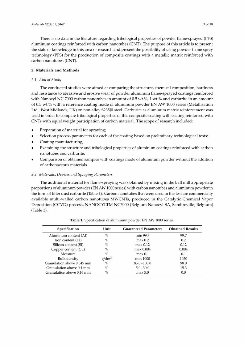
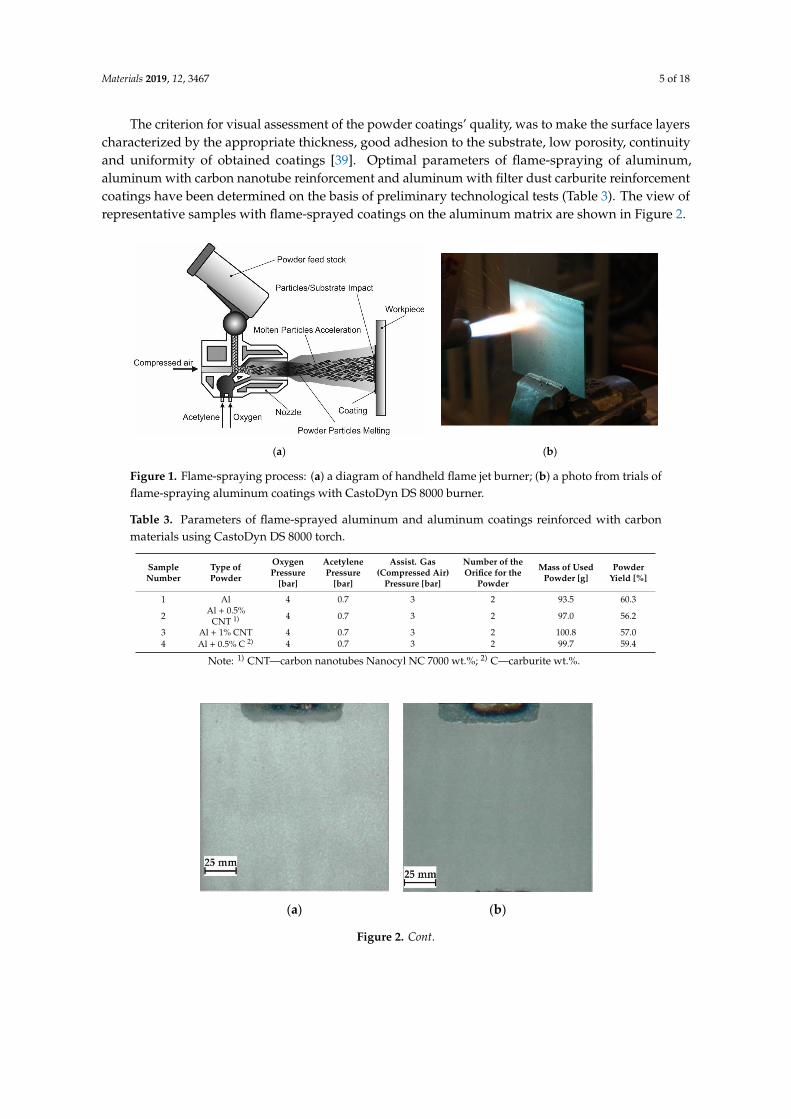
The criterion for visual assessment of the powder coatings’ quality, was to make the surface layerscharacterized by the appropriate thickness, good adhesion to the substrate, low porosity, continuityand uniformity of obtained coatings [39]. Optimal parameters of flame-spraying of aluminum,aluminum with carbon nanotube reinforcement and aluminum with filter dust carburite reinforcementcoatings have been determined on the basis of preliminary technological tests (Table 3). The view ofrepresentative samples with flame-sprayed coatings on the aluminum matrix are shown in Figure 2.
Materials 2019, 12, x FOR PEER REVIEW 5 of 17
reinforcement coatings have been determined on the basis of preliminary technological tests (Table
3). The view of representative samples with flame-sprayed coatings on the aluminum matrix are
shown in Figure 2.
(a) (b)
Figure 1. Flame-spraying process: (a) a diagram of handheld flame jet burner; (b) a photo from trials
of flame-spraying aluminum coatings with CastoDyn DS 8000 burner.
Table 3. Parameters of flame-sprayed aluminum and aluminum coatings reinforced with carbon
materials using CastoDyn DS 8000 torch.
Sample
Number Type of Powder
Oxygen
Pressure
[bar]
Acetylene
Pressure
[bar]
Assist. Gas
(Compressed
Air) Pressure
[bar]
Number of
the Orifice
for the
Powder
Mass of
Used
Powder
[g]
Powder
Yield
[%]
1 Al 4 0.7 3 2 93.5 60.3
2 Al + 0.5% CNT1) 4 0.7 3 2 97.0 56.2
3 Al + 1% CNT 4 0.7 3 2 100.8 57.0
4 Al + 0.5% C2) 4 0.7 3 2 99.7 59.4
Note: 1) CNT—carbon nanotubes Nanocyl NC 7000 wt.%; 2) C—carburite wt.%.
(a) (b)
Figure 1. Flame-spraying process: (a) a diagram of handheld flame jet burner; (b) a photo from trials offlame-spraying aluminum coatings with CastoDyn DS 8000 burner.
Table 3. Parameters of flame-sprayed aluminum and aluminum coatings reinforced with carbonmaterials using CastoDyn DS 8000 torch.
SampleNumber
Type ofPowder
OxygenPressure
[bar]
AcetylenePressure
[bar]
Assist. Gas(Compressed Air)
Pressure [bar]
Number of theOrifice for the
Powder
Mass of UsedPowder [g]
PowderYield [%]
1 Al 4 0.7 3 2 93.5 60.3
2 Al + 0.5%CNT 1) 4 0.7 3 2 97.0 56.2
3 Al + 1% CNT 4 0.7 3 2 100.8 57.04 Al + 0.5% C 2) 4 0.7 3 2 99.7 59.4
Note: 1) CNT—carbon nanotubes Nanocyl NC 7000 wt.%; 2) C—carburite wt.%.
Materials 2019, 12, x FOR PEER REVIEW 5 of 18
The criterion for visual assessment of the powder coatings’ quality, was to make the surface
layers characterized by the appropriate thickness, good adhesion to the substrate, low porosity,
continuity and uniformity of obtained coatings [39]. Optimal parameters of flame-spraying of
aluminum, aluminum with carbon nanotube reinforcement and aluminum with filter dust carburite
reinforcement coatings have been determined on the basis of preliminary technological tests (Table
3). The view of representative samples with flame-sprayed coatings on the aluminum matrix are
shown in Figure 2.
(a) (b)
Figure 1. Flame-spraying process: (a) a diagram of handheld flame jet burner [40]; (b) a photo from
trials of flame-spraying aluminum coatings with CastoDyn DS 8000 burner.
Table 3. Parameters of flame-sprayed aluminum and aluminum coatings reinforced with carbon
materials using CastoDyn DS 8000 torch.
Sample
Number Type of Powder
Oxygen
Pressure
[bar]
Acetylene
Pressure
[bar]
Assist. Gas
(Compressed
Air) Pressure
[bar]
Number of
the Orifice
for the
Powder
Mass of
Used
Powder
[g]
Powder
Yield
[%]
1 Al 4 0.7 3 2 93.5 60.3
2 Al + 0.5% CNT1) 4 0.7 3 2 97.0 56.2
3 Al + 1% CNT 4 0.7 3 2 100.8 57.0
4 Al + 0.5% C2) 4 0.7 3 2 99.7 59.4
Note: 1) CNT—carbon nanotubes Nanocyl NC 7000 wt.%; 2) C—carburite wt.%.
(a) (b)
Figure 2. Cont.

Materials 2019, 12, 3467 6 of 18Materials 2019, 12, x FOR PEER REVIEW 6 of 18
(c) (d)
Figure 2. View of test samples with flame-sprayed coatings on the aluminum matrix: (a) aluminum
powder of the EN AW 1000 series; (b) aluminum powder EN AW 1000 series with addition of 0.5
wt.% carbon nanotubes (Nanocyl NC 7000); (c) aluminum powder of the EN AW 1000 series with the
addition of 1 wt.% carbon nanotubes (Nanocyl NC 7000); (d) aluminum powder of the EN AW 1000
series with the addition of 1 wt.% carburite.
2.3. Visual and Metallographic Examination of Coatings
In each case, the entire surface of the sample was subjected to visual tests to assess the quality
and identify any imperfections in the form of cracks, discontinuities, unevenness, porosity or lack of
coating adhesion. Macro and microscopic examinations were performed on Olypmus GX 71 optical
microscope (Olympus Corporation, Tokyo, Japan). The observations were made on the cross-section
of metallographic samples cut from the centre of element. Samples were polished and etched in Aqua
Regia. Selected areas of flame-sprayed coatings (aluminum and aluminum with addition of carbon
materials) have been subjected to chemical composition analysis on JEOL 5800LV SEM scanning
microscope and also EDX (Jeol Ltd., Tokyo, Japan).
2.4. Hardness Measurements of Coatings
The coating-hardness measurement was made with the Vickers method using Microhardness
Tester 401MVD™ (Wilson Instruments An Instron Company, MA, USA). The examinations were
carried out in conformity to ISO 6507-1:2018 standard [41]. The load applied during the hardness
measurement was 0.98 N. The hardness measurement was made at the polished cross-section of the
samples with flame-sprayed coatings. Ten hardness measuring points were made on the cross-section
each sprayed coating.
2.5. Erosive Wear Resistance of Coatings
The erosive wear tests of flame-sprayed coatings were carried out in accordance with ASTM
G76-95 [42], as shown in Figure 3. Aluminum oxide powder (Al2O3) with particle diameter of 71 µm
was used as the erodent material. Particle velocity was set at 70 ± 2 m/s, the erodent expenditure was
2.0 ± 0.5 g/min and the nozzle distance from the sample surface was 10 mm. The tests were carried
out at 90° and 30° erodent impact angle. The average weight loss was determined based on three
tests. The erosion rate was determined according to the Equation (1),
erosion rate [g/min] = mass loss of sample [g]:exposure time [min] (1)
However, the erosive wear resistance using Equation (2):
erosive wear resistance [0.001mm3/g] = volume loss of the sample [mm3]:
total mass of the erodent used in the test [g] (2)
Figure 2. View of test samples with flame-sprayed coatings on the aluminum matrix: (a) aluminumpowder of the EN AW 1000 series; (b) aluminum powder EN AW 1000 series with addition of 0.5 wt.%carbon nanotubes (Nanocyl NC 7000); (c) aluminum powder of the EN AW 1000 series with the additionof 1 wt.% carbon nanotubes (Nanocyl NC 7000); (d) aluminum powder of the EN AW 1000 series withthe addition of 1 wt.% carburite.
2.3. Visual and Metallographic Examination of Coatings
In each case, the entire surface of the sample was subjected to visual tests to assess the qualityand identify any imperfections in the form of cracks, discontinuities, unevenness, porosity or lack ofcoating adhesion. Macro and microscopic examinations were performed on Olypmus GX 71 opticalmicroscope (Olympus Corporation, Tokyo, Japan). The observations were made on the cross-sectionof metallographic samples cut from the centre of element. Samples were polished and etched inAqua Regia. Selected areas of flame-sprayed coatings (aluminum and aluminum with addition ofcarbon materials) have been subjected to chemical composition analysis on JEOL 5800LV SEM scanningmicroscope and also EDX (Jeol Ltd., Tokyo, Japan).
2.4. Hardness Measurements of Coatings
The coating-hardness measurement was made with the Vickers method using MicrohardnessTester 401MVD™ (Wilson Instruments An Instron Company, Norwood, MA, USA). The examinationswere carried out in conformity to ISO 6507-1:2018 standard [40]. The load applied during the hardnessmeasurement was 0.98 N. The hardness measurement was made at the polished cross-section of thesamples with flame-sprayed coatings. Ten hardness measuring points were made on the cross-sectioneach sprayed coating.
2.5. Erosive Wear Resistance of Coatings
The erosive wear tests of flame-sprayed coatings were carried out in accordance with ASTMG76-95 [41], as shown in Figure 3. Aluminum oxide powder (Al2O3) with particle diameter of 71 µmwas used as the erodent material. Particle velocity was set at 70 ± 2 m/s, the erodent expenditure was2.0 ± 0.5 g/min and the nozzle distance from the sample surface was 10 mm. The tests were carried outat 90◦ and 30◦ erodent impact angle. The average weight loss was determined based on three tests.The erosion rate was determined according to the Equation (1),
erosion rate [g/min] = mass loss of sample [g]:exposure time [min] (1)
However, the erosive wear resistance using Equation (2):
erosive wear resistance [0.001mm3/g] = volume loss of the sample [mm3]:total mass of the erodent used in the test [g]
(2)

Materials 2019, 12, 3467 7 of 18Materials 2019, 12, x FOR PEER REVIEW 7 of 18
Figure 3. Erosion resistance testing according to ASTM G 76-95 [42]: (a) a schematic view, (b) the
interior view of the erosion measuring chamber.
2.6. Abrasive Wear Resistance of Coatings
Metal-mineral wear resistance tests of aluminum matrix coatings were provided in accordance
with ASTM G65-00, Procedure E [43]. During the test, the rubber-wheel made 1000 revolutions and
the abrasive flow rate of A.F.S. Testing Sand 50–70 was 335 g/min. The force applied pressing the test
coupon against the wheel was TL = 130 N (test load-TL). After the abrasive wear resistance test, the
test specimen was weighed at weight sensitivity 0,0001 [g]. Converting mass loss to volume loss was
as follows:
volume loss [mm3] = mass loss [g]:density [g/cm3] x 1000 (3)
The tests were carried out on abrasion tester shown in Figure 4.
(a) (b)
Figure 4. Metal-mineral wear resistance test stand–according to ASTM G65–00, Procedure E standard
[43] (a) a schematic view, (b) picture of the device used.
3. Results
(a) (b)
Figure 3. Erosion resistance testing according to ASTM G 76-95: (a) a schematic view, (b) the interiorview of the erosion measuring chamber.
2.6. Abrasive Wear Resistance of Coatings
Metal-mineral wear resistance tests of aluminum matrix coatings were provided in accordancewith ASTM G65-00, Procedure E [42]. During the test, the rubber-wheel made 1000 revolutions andthe abrasive flow rate of A.F.S. Testing Sand 50–70 was 335 g/min. The force applied pressing the testcoupon against the wheel was TL = 130 N (test load-TL). After the abrasive wear resistance test, thetest specimen was weighed at weight sensitivity 0.0001 [g]. Converting mass loss to volume loss wasas follows:
volume loss [mm3] = mass loss [g]:density [g/cm3] x 1000 (3)
The tests were carried out on abrasion tester shown in Figure 4.
Materials 2019, 12, x FOR PEER REVIEW 7 of 18
Figure 3. Erosion resistance testing according to ASTM G 76-95 [42]: (a) a schematic view, (b) the
interior view of the erosion measuring chamber.
2.6. Abrasive Wear Resistance of Coatings
Metal-mineral wear resistance tests of aluminum matrix coatings were provided in accordance
with ASTM G65-00, Procedure E [43]. During the test, the rubber-wheel made 1000 revolutions and
the abrasive flow rate of A.F.S. Testing Sand 50–70 was 335 g/min. The force applied pressing the test
coupon against the wheel was TL = 130 N (test load-TL). After the abrasive wear resistance test, the
test specimen was weighed at weight sensitivity 0,0001 [g]. Converting mass loss to volume loss was
as follows:
volume loss [mm3] = mass loss [g]:density [g/cm3] x 1000 (3)
The tests were carried out on abrasion tester shown in Figure 4.
(a) (b)
Figure 4. Metal-mineral wear resistance test stand–according to ASTM G65–00, Procedure E standard
[43] (a) a schematic view, (b) picture of the device used.
3. Results
(a) (b)
Figure 4. Metal-mineral wear resistance test stand–according to ASTM G65–00, Procedure E standard (a)a schematic view, (b) picture of the device used.

Materials 2019, 12, 3467 8 of 18
3. Results
3.1. Metallographic Test Results
The structure of each tested flame-sprayed coating cross-section is presented in Figure 5. The SEMstructures of tested aluminum matrix coatings with chemical composition are presented in Figures 6–9.
Materials 2019, 12, x FOR PEER REVIEW 8 of 18
3.1. Metallographic Test Results
The structure of each tested flame-sprayed coating cross-section is presented in Figure 5. The
SEM structures of tested aluminum matrix coatings with chemical composition are presented in
Figures 6–9.
Al Al + 0.5% CNT
Al + 1% CNT Al + 0.5% C
Figure 5. The macro and microstructure of the flame-sprayed pure aluminum and aluminum matrix
with carbon nanotubes and carburite reinforcement coatings; etching: HCl + HNO3.
Figure 5. The macro and microstructure of the flame-sprayed pure aluminum and aluminum matrixwith carbon nanotubes and carburite reinforcement coatings; etching: HCl + HNO3.

Materials 2019, 12, 3467 9 of 18
Materials 2019, 12, x FOR PEER REVIEW 9 of 18
Al
Measurement area sign Chemical composition [wt.%]
C O Al
Spectrum 1 5 2 93
Spectrum 2 6 2 92
Spectrum 3 26 27 47
Standard deviation 12 14 26
Figure 6. The structure of EN AW 1000 aluminum powder flame-sprayed coating with marked
chemical composition tested areas on SEM.
Al + 0.5% CNT
Measurement area sign Chemical composition [wt.%]
C Al
Spectrum 1 6 94
Spectrum 2 12 88
Spectrum 3 33 67
Standard deviation 14 14
Figure 7. The structure of aluminum powder with 0.5 wt.% Nanocyl NC 7000 carbon nanotubes
flame-sprayed coating with marked chemical composition tested areas on SEM.
Figure 6. The structure of EN AW 1000 aluminum powder flame-sprayed coating with marked chemicalcomposition tested areas on SEM.
Materials 2019, 12, x FOR PEER REVIEW 9 of 18
Al
Measurement area sign Chemical composition [wt.%]
C O Al
Spectrum 1 5 2 93
Spectrum 2 6 2 92
Spectrum 3 26 27 47
Standard deviation 12 14 26
Figure 6. The structure of EN AW 1000 aluminum powder flame-sprayed coating with marked
chemical composition tested areas on SEM.
Al + 0.5% CNT
Measurement area sign Chemical composition [wt.%]
C Al
Spectrum 1 6 94
Spectrum 2 12 88
Spectrum 3 33 67
Standard deviation 14 14
Figure 7. The structure of aluminum powder with 0.5 wt.% Nanocyl NC 7000 carbon nanotubes
flame-sprayed coating with marked chemical composition tested areas on SEM.
Figure 7. The structure of aluminum powder with 0.5 wt.% Nanocyl NC 7000 carbon nanotubesflame-sprayed coating with marked chemical composition tested areas on SEM.

Materials 2019, 12, 3467 10 of 18
Materials 2019, 12, x FOR PEER REVIEW 10 of 18
Al + 1% CNT
Measurement area sign Chemical composition [wt.%]
C Al
Spectrum 1 17 83
Spectrum 2 20 80
Spectrum 3 7 93
Standard deviation 7 7
Figure 8. The structure of aluminum powder with 1 wt.% Nanocyl NC 7000 carbon nanotubes flame-
sprayed coating with marked chemical composition tested areas on SEM.
Al + 0.5% C
Measurement area sign Chemical composition [wt.%]
C Al
Spectrum 1 4 96
Spectrum 2 5 95
Spectrum 3 60 40
Standard deviation 32 32
Figure 9. The structure of aluminum powder with 0.5 wt.% carburite carbon nanotubes flame-sprayed
coating with marked chemical composition tested areas on SEM.
3.2. Hardness Measurements
Figure 8. The structure of aluminum powder with 1 wt.% Nanocyl NC 7000 carbon nanotubesflame-sprayed coating with marked chemical composition tested areas on SEM.
Materials 2019, 12, x FOR PEER REVIEW 10 of 18
Al + 1% CNT
Measurement area sign Chemical composition [wt.%]
C Al
Spectrum 1 17 83
Spectrum 2 20 80
Spectrum 3 7 93
Standard deviation 7 7
Figure 8. The structure of aluminum powder with 1 wt.% Nanocyl NC 7000 carbon nanotubes flame-
sprayed coating with marked chemical composition tested areas on SEM.
Al + 0.5% C
Measurement area sign Chemical composition [wt.%]
C Al
Spectrum 1 4 96
Spectrum 2 5 95
Spectrum 3 60 40
Standard deviation 32 32
Figure 9. The structure of aluminum powder with 0.5 wt.% carburite carbon nanotubes flame-sprayed
coating with marked chemical composition tested areas on SEM.
3.2. Hardness Measurements
Figure 9. The structure of aluminum powder with 0.5 wt.% carburite carbon nanotubes flame-sprayedcoating with marked chemical composition tested areas on SEM.

Materials 2019, 12, 3467 11 of 18
3.2. Hardness Measurements
The hardness measurements on flame-sprayed aluminum and aluminum matrix reinforced withcarbon material coatings, were carried out on the surface at 5 points along one measuring line (Table 4)and on cross-section of the samples (Figures 10 and 11), according to the scheme showed on Figure 10.
Table 4. Surface hardness results of the flame-sprayed aluminum and aluminum reinforced withcarbon material coatings.
Specimen Designation
Hardness [HV 0.1]
Measuring Point
1 2 3 4 5 Average Standard Deviation
Al 35.2 32.5 34.8 37.2 35.1 34.96 1.67
Al + 0.5% CNT 59.2 62.8 56.5 54.2 55.5 57.64 3.42
Al + 1% CNT 41.2 43.2 37.5 39.2 38.7 39.96 2.25
Al + 0.5% C 30.2 27.3 28.2 27.0 28.0 28.14 1.25
Materials 2019, 12, x FOR PEER REVIEW 11 of 18
The hardness measurements on flame-sprayed aluminum and aluminum matrix reinforced with
carbon material coatings, were carried out on the surface at 5 points along one measuring line (Table
4) and on cross-section of the samples (Figures 10 and 11), according to the scheme showed on Figure
10.
Table 4. Surface hardness results of the flame-sprayed aluminum and aluminum reinforced with
carbon material coatings.
Specimen Designation
Hardness [HV 0.1]
Measuring Point
1 2 3 4 5 Average Standard Deviation
Al 35.2 32.5 34.8 37.2 35.1 34.96 1.67
Al + 0.5% CNT 59.2 62.8 56.5 54.2 55.5 57.64 3.42
Al + 1% CNT 41.2 43.2 37.5 39.2 38.7 39.96 2.25
Al + 0.5% C 30.2 27.3 28.2 27.0 28.0 28.14 1.25
Specimen
Designation
Hardness [HV 0.1]
Measuring Point
1 2 3 4 5 6 7 8 9 10 Average Standard
Deviation
Al 34.9 46.2 31.8 28.3 29.6 41.0 40.5 34.2 30.3 24.1 34.1 6.39
Al + 0.5%
CNT 58.8 30.6 39.4 41.2 49.4 33.7 46.1 48.1 38.3 37.3 42.3 7.95
Al + 1% CNT 40.1 54.4 51.0 55.3 42.1 29.2 32.1 34.5 48.1 49.5 43.6 8.95
Al + 0.5% C 27.5 40.1 34.2 41.1 31.6 34.9 31.8 33.7 36.8 41.2 35.3 4.29
Figure 10. Hardness measurements scheme and HV 0.1 results of the flame-sprayed aluminum and
aluminum reinforced with carbon materials coatings. Figure 10. Hardness measurements scheme and HV 0.1 results of the flame-sprayed aluminum andaluminum reinforced with carbon materials coatings.

Materials 2019, 12, 3467 12 of 18Materials 2019, 12, x FOR PEER REVIEW 12 of 18
Figure 11. Comparison of average cross-sectional hardness and standard deviation for each of the
investigated coatings.
3.3. Tests Results of the Coatings Erosive Wear Resistance
The relative erosive wear resistance test results of the flame-sprayed aluminum, aluminum with
carbon nanotube reinforcement and aluminum with filter dust carburite reinforcement coatings are
presented in Table 5 and Figure 12.
Table 5. Summary of results obtained during the erosion wear test ASTM G76−95 [42].
Erodent
Strike Angle
[°]
Specimen Designation Mass Loss
[g]
Volume
Loss
[mm3]
Erosion Rate
[g/min]
Resistance to Erosion
as per ASTM G76
[0.001mm3/g]
90
Al 0.0054 1.985 0.00068 0.12255
Al + 0.5% CNT 0.0117 4.301 0.00146 0.26552
Al + 1% CNT 0.0071 2.610 0.00089 0.16113
Al + 0.5% C 0.0064 2.353 0.00080 0.14524
30
Al 0.0036 1.324 0.00045 0.08170
Al + 0.5% CNT 0.0066 2.426 0.00083 0.14978
Al + 1% CNT 0.0045 1.654 0.00056 0.10212
Al + 0.5% C 0.0039 1.434 0.00049 0.08851
Notes: density of aluminum spray coating 2.72 [g/cm3], mass of erodent used 16.2 [g], test time 8 [min].
3.4. Tests Results of the Coatings’ Wear Resistance
The wear resistance test results of the flame-sprayed aluminum, aluminum with carbon
nanotube reinforcement and aluminum with filter dust carburite reinforcement coatings are
presented in Table 6 and Figure 13. The metal-mineral type wear resistance of the flame-sprayed
aluminum with carbon nanotubes and aluminum with carburite coatings were compared to the
flame-sprayed pure aluminum coating.
Figure 11. Comparison of average cross-sectional hardness and standard deviation for each of theinvestigated coatings.
3.3. Tests Results of the Coatings Erosive Wear Resistance
The relative erosive wear resistance test results of the flame-sprayed aluminum, aluminum withcarbon nanotube reinforcement and aluminum with filter dust carburite reinforcement coatings arepresented in Table 5 and Figure 12.
Table 5. Summary of results obtained during the erosion wear test ASTM G76−95 [41].
Erodent StrikeAngle [◦]
SpecimenDesignation Mass Loss [g] Volume Loss
[mm3]Erosion Rate
[g/min]
Resistance to Erosionas per ASTM G76
[0.001mm3/g]
90
Al 0.0054 1.985 0.00068 0.12255Al + 0.5% CNT 0.0117 4.301 0.00146 0.26552Al + 1% CNT 0.0071 2.610 0.00089 0.16113Al + 0.5% C 0.0064 2.353 0.00080 0.14524
30
Al 0.0036 1.324 0.00045 0.08170Al + 0.5% CNT 0.0066 2.426 0.00083 0.14978Al + 1% CNT 0.0045 1.654 0.00056 0.10212Al + 0.5% C 0.0039 1.434 0.00049 0.08851
Notes: density of aluminum spray coating 2.72 [g/cm3], mass of erodent used 16.2 [g], test time 8 [min].

Materials 2019, 12, 3467 13 of 18Materials 2019, 12, x FOR PEER REVIEW 13 of 18
Erodent strike
angle [°] Specimen designation
90
Al Al + 0.5% CNT
Al + 1% CNT Al + 0.5% C
30
Al Al + 0.5% CNT
Al + 1% CNT Al + 0.5% C
Figure 12. The surfaces of flame-sprayed aluminum and aluminum matrix reinforced with carbon
material coatings after erosive wear resistance tests; comparison the erosion effect on samples
surfaces for each tested angle of erodent particles incidence.
Table 6. Summary of results obtained during the abrasive wear test ASTM G65 [43].
Specimen
Designation
Number
of
Specimen
Weight
Before Test
[g]
Weight
after Test
[g]
Mass
Loss [g]
Average
Mass
Loss [g]
Average
Volume
Loss [mm3]
Relative 1)
Abrasion
Resistance
Al S1-1 43.9675 43.8413 0.1262
0.1418 52.1324 1.00 S1-2 42.3855 42.2281 0.1574
Al + 0.5% CNT S2-1 56.5170 56.3924 0.1246
0.1286 47.26103 1.10 S2-2 53.8604 53.7279 0.1325
Figure 12. The surfaces of flame-sprayed aluminum and aluminum matrix reinforced with carbonmaterial coatings after erosive wear resistance tests; comparison the erosion effect on samples surfacesfor each tested angle of erodent particles incidence.
3.4. Tests Results of the Coatings’ Wear Resistance
The wear resistance test results of the flame-sprayed aluminum, aluminum with carbon nanotubereinforcement and aluminum with filter dust carburite reinforcement coatings are presented inTable 6 and Figure 13. The metal-mineral type wear resistance of the flame-sprayed aluminum withcarbon nanotubes and aluminum with carburite coatings were compared to the flame-sprayed purealuminum coating.

Materials 2019, 12, 3467 14 of 18
Table 6. Summary of results obtained during the abrasive wear test ASTM G65 [42].
SpecimenDesignation
Numberof
Specimen
WeightBeforeTest [g]
Weightafter Test
[g]
Mass Loss[g]
AverageMass Loss
[g]
AverageVolume Loss
[mm3]
Relative 1)
AbrasionResistance
AlS1-1 43.9675 43.8413 0.1262
0.1418 52.1324 1.00S1-2 42.3855 42.2281 0.1574
Al + 0.5%CNT
S2-1 56.5170 56.3924 0.12460.1286 47.26103 1.10S2-2 53.8604 53.7279 0.1325
Al + 1%CNT
S3-1 56.9638 56.8322 0.13160.1279 47.0221 1.11S3-2 57.4587 57.3345 0.1242
Al + 0.5% CS4-1 59.4423 59.3199 0.1224
0.1190 43.7500 1.19S4-2 61.1152 60.9996 0.1156
Notes: density of aluminum spray coating 2.72 [g/cm3]; 1) relative to sprayed coatings of the aluminum withoutcarbon materials.
Materials 2019, 12, x FOR PEER REVIEW 14 of 18
Al + 1% CNT S3-1 56.9638 56.8322 0.1316
0.1279 47.0221 1.11 S3-2 57.4587 57.3345 0.1242
Al + 0.5% C S4-1 59.4423 59.3199 0.1224
0.1190 43.7500 1.19 S4-2 61.1152 60.9996 0.1156
Notes: density of aluminum spray coating 2.72 [g/cm3]; 1) relative to sprayed coatings of the aluminum
without carbon materials.
Specimen designation / Number of specimen
Al / S1-1 Al / S1-2
Al + 0.5% CNT / S2-1 Al + 0.5% CNT / S2-2
Al + 1% CNT / S3-1 Al + 1% CNT / S3-2
Al + 0.5% C / S4-1 Al + 0.5% C / S4-2
Figure 13. The surfaces of flame-sprayed aluminum and aluminum with carbon material coatings
after wear resistance metal-mineral tests.
4. Discussion
Visual and metallographic tests of the flame-sprayed aluminum and aluminum with carbon
material reinforcement (0.5 wt.% and 1 wt.% of carbon nanotubes Nanocyl NC 7000 and 0.5 wt.% of
carburite) have shown that by using proper parameters of the process it is possible to receive coatings
with acceptable quality level, characterized by proper adhesion to the substrate, lack of delamination
and even thickness over the entire surface. The outer surface of the coatings was characterized by a
slight roughness, lack of porosity and cracks (Figure 2). During the flame-spraying process, carbon
material particles added to aluminum powder did not oxidize completely in the oxyacetylene flame.
Figure 13. The surfaces of flame-sprayed aluminum and aluminum with carbon material coatings afterwear resistance metal-mineral tests.

Materials 2019, 12, 3467 15 of 18
4. Discussion
Visual and metallographic tests of the flame-sprayed aluminum and aluminum with carbonmaterial reinforcement (0.5 wt.% and 1 wt.% of carbon nanotubes Nanocyl NC 7000 and 0.5 wt.% ofcarburite) have shown that by using proper parameters of the process it is possible to receive coatingswith acceptable quality level, characterized by proper adhesion to the substrate, lack of delaminationand even thickness over the entire surface. The outer surface of the coatings was characterizedby a slight roughness, lack of porosity and cracks (Figure 2). During the flame-spraying process,carbon material particles added to aluminum powder did not oxidize completely in the oxyacetyleneflame. Carbon nanotubes (melting point 4526 ◦C [43]) and carburite (melting point 3550 ◦C [44])in the oxyacetylene flame has formed with aluminum Al-Cx type agglomerates, which due to thelarge volume and lower heat source temperature than other thermal spraying methods (oxyacetyleneflame temperature 3160 ◦C [45]) migrated in large quantities to the coatings. Partially melted andpartially only plasticized in a gas flame, Al-Cx agglomerates collided with the substrate at highspeed, (Figure 1b) and in this way formed a fine-grained coating structure. Powder flame sprayingprocess (PFS) in comparison with, for example, plasma spraying, increases the probability of stoppingcarburite and carbon nanotubes (CNT) in flame sprayed composite coating with aluminum matrix.Presence of carbon materials in aluminum powder flame-sprayed coatings is initially confirmed bymetallographic microscopic tests, which revealed areas carburite and carbon nanotubes on specimens(Figure 5, Al + 0.5% CNT). Presence of carbon materials can be observed on the entire cross-sectionof the coating, also at the outer surface. Inside the Al-Cx composite coatings, no cracks were found,only the presence of individual cavities. The tests made using scanning electron microscope haveshown presence of some areas consisting small carbon materials inclusions. These were observed inthe all-aluminum coatings with carbon material reinforcement. For the coating with 0.5 wt.% CNT,inclusion areas consisted of 33.05 wt.% C; for coating with 1 wt.% CNT, the carbon content was lowerin tested area (20.25 wt.% C), while for the coating with 0.5 wt.% of carburite, carbon content wasalmost two times higher than in the coating with same content of CNTs and amounted to 59.76 wt.% C.In aluminum coating without carbon material addition, carbon and oxygen were found, (Figure 6). Asmall amount of carbon in the aluminum coating may be caused by the ease of thermal decompositionof acetylene in the gas flame and the physicochemical properties of unsaturated hydrocarbons [46].Acetylene is dissociated into active carbon atoms (acetylene black, characterized by high purity) andhydrogen molecule. The oxygen content in the aluminum coating is the result of oxidation of thealuminum particles in the gas flame and the atmosphere. The addition of carbon materials to thealuminum powder causes the carbon to bind oxygen as a strong deoxidizer; that is why its presencewas not found in composite coatings with aluminum matrix and carbon material (carburite and carbonnanotubes) reinforcement. These results should still be confirmed using more advanced researchmethods, e.g. XRD X-ray diffraction or Raman spectroscopy. These studies will be completed andpresented in another publication.
The hardness measurements of tested coatings were proceeded using standard ISO 6507 [40]. Themeasurements were done both on the external surface and the cross-section of the sprayed coatings.These tests showed that using addition of 0.5 wt.% and 1 wt.% carbon nanotubes to aluminum coating(34.1 HV 0.1) caused an increase in its hardness of 8.2 HV 0.1 for the 0.5 wt.% of carbon nanotubereinforcement and by 9.5 HV 0.1 for 1 wt.% of carbon nanotube reinforcement. Addition of carburite toaluminum had not significant influence on the coating hardness (Figure 11).
Erosive wear resistance test results have shown that the addition of carbon materials to aluminumpowder does not increase the erosive wear resistance of flame-sprayed coatings. During these tests,the aluminum coatings with carbon nanotubes had worn out by erosion with large and small anglesof erodent incidence more than aluminum coatings with carburite and much more than aluminumcoatings without carbon materials reinforcement. It was observed that for all tested coatings erosivewear resistance was better during using smaller angle of erodent incidence (Table 4).

Materials 2019, 12, 3467 16 of 18
The best metal-mineral type wear resistance had the aluminum coating with carburite. The wearresistance of this coating was 19% higher than pure aluminum coating. The aluminum coatings withaddition of 0.5 wt.% and 1 wt.% of carbon nanotubes in comparison to pure aluminum coating hadbetter relative wear resistance by 10% and 11% (Table 5). The cause of decreasing wear using aluminumcoatings with carbon material addition was increased glide of ceramic abrasive particles on metal.
Based on the conducted study and the obtained results, it can be concluded that it is possible tointroduce carbon particles in the form of carbon nanotubes (CNT) and also carburite into the aluminummatrix by means of flame spraying method. The flame spraying is an effective and cheaper alternativeto the technology of laser surface treatment of metals. Properly selected parameters of the flamespraying process allow to preserve the properties of particles of carbon materials, their even distributionin the coating, proper bonding with the matrix and prevent the effects of their thermal degradation.The produced composite is characterized by a low friction coefficient. The tribological characteristicsof produced test coating of aluminum reinforced by carbon particles in the form of carbon nanotubesand carburite show that the coatings can be classified as sliding materials. Additionally, the coatingsare characterized by high wear resistance. The obtained result should be considered as a preliminaryinformation on a new group of materials, which can find application in the automotive industry. Theyare the basis for the design and optimization of friction materials operated at elevated temperatures(e.g. pistons, engine blocks), systems subject to intensive wear (e.g. brake discs, cylinders), as wellas in propulsion systems (e.g. bearings), providing low friction coefficient and also high ability forabsorption of vibration. Further research should be focused on the investigation of the effect of dopingthe aluminum matrix with carbon nanotubes (CNT) on the wear mechanisms, change of microstructureof the counter-specimen and also tests which will allow to determine the tribological characteristics ofthe materials at elevated temperatures.
5. Conclusions
The analysis carried out comparing properties of flame-sprayed EN AW 1000 aluminum coatingsand aluminum matrix coatings with carbon materials reinforcement (0.5 wt.% and 1 wt.% of NanocylNC 7000 carbon nanotubes and 0.5 wt.% of carburite) resulted in the following conclusions:
1. Producing aluminum matrix coatings with carbon materials reinforcement with high quality ispossible using flame spraying technology.
2. In the aluminum with carburite reinforcement flame-sprayed coating structure, areas wereobserved with a share of carbon above 61 wt.%. In the aluminum coating with 1 of carbonnanotubes, similar areas were observed with a share of carbon about 33 wt.%.
3. The addition of carbon nanotubes to aluminum powder resulted in increasing the hardness offlame-sprayed coatings by about 10 HV 0.1.
4. The carbon materials reinforced aluminum flame-sprayed coatings have lower erosive wearresistance than pure aluminum coatings with large and small angles of erodent incidence.
5. The metal-mineral type wear resistance of flame-sprayed aluminum coatings reinforced withcarbon nanotubes or carburite is 10% to 20% higher in comparison to pure aluminum coating.
Funding: This research was financed from the own resources of the Silesian University of Technology.
Conflicts of Interest: The author declare no conflict of interest.
References
1. Kelly, A. Composite materials after seventy years. J. Mater. Sci. 2006, 41, 905–912. [CrossRef]2. Rawal, S. Metal-matrix composites for space applications. JOM 2001, 53, 14–17. [CrossRef]3. Shelly, J.S.; LeClaire, R.; Nichols, J. Metal-matrix composites for liquid rocket engines. JOM 2001, 53, 18–21.
[CrossRef]

Materials 2019, 12, 3467 17 of 18
4. Salvetat, J.P.; Bonard, J.M.; Thomson, N.H.; Kulik, A.J.; Forro, L.; Benoit, W.; Zuppiroli, L. Mechanicalproperties of carbon nanotubes. Appl. Phys. A 1999, 69, 255–260. [CrossRef]
5. Coleman, J.N.; Khan, U.; Blau, W.J.; Gun’ko, Y.K. Small but strong: A review of the mechanical properties ofcarbon nanotube–polymer composites. Carbon 2006, 44, 1624–1652. [CrossRef]
6. Takashi, I. Overview of trends in advanced composite research and applications in Japan. Adv. Compos.Mater. 2006, 15, 3–37.
7. Bokobza, L. Multiwall carbon nanotube elastomeric composites. A review. Polymer 2007, 48, 4907–4920.[CrossRef]
8. Curtin, W.A.; Sheldon, B.W. CNT-reinforced ceramics and metals. Mater. Today 2004, 7, 44–49. [CrossRef]9. Saffar, K.P.A.; Najafi, A.R.; Moeinzadeh, M.H.; Sudak, L.J. A Finite Element Study of Crack Behavior for
Carbon Nanotube Reinforced Bone Cement. World J. Mech. 2013, 3, 13–21. [CrossRef]10. Bakshi, S.R.; Singh, V.; Balani, K.; McCartney, D.G.; Seal, S.; Agarwal, A. Carbon nanotube reinforced
aluminum composite coating via cold spraying. Surf. Coat. Technol. 2008, 202, 5162–5169. [CrossRef]11. Keshri, A.K.; Balani, K.; Bakshi, S.R.; Singh, V.; Laha, T.; Seal, S.; Agarwal, A. Structural transformations in
carbon nanotubes during thermal spray processing. Surf. Coat. Technol. 2009, 203, 2193–2201. [CrossRef]12. Wu, Y.; Kim, G. Carbon nanotube reinforced aluminum composite fabricated by semi-solid powder processing.
J. Mater. Process. Technol. 2011, 211, 1341–1347. [CrossRef]13. Liao, J.; Tan, M.; Ramanujan, R.V.; Shukla, S. Carbon nanotube evolution in aluminum matrix during
composite fabrication process. Mater. Sci. Forum 2011, 690, 294–297. [CrossRef]14. Feng, Y.; Yuana, H.; Zhanga, M. Fabrication and properties of silver-matrix composites reinforced by carbon
nanotubes. Mater. Charact. 2005, 55, 211–218. [CrossRef]15. Bakshia, S.R.; Singhb, V.; Seal, S.; Agarwal, A. Aluminum composite reinforced with multiwalled carbon
nanotubes from plasma spraying of spray dried powders. Surf. Coat. Technol. 2009, 203, 1544–1554.[CrossRef]
16. Zeng, X.; Zhou, G.; Xu, Q.; Xiong, Y.; Luo, C.H.; Wu, J. A new technique for dispersion of carbon nanotube ina metal melt. Mater. Sci. Eng. A 2010, 527, 5335–5340. [CrossRef]
17. Kondoh, K.; Fukuda, H.; Umeda, J.; Imai, H.; Fugetsu, B.; Endo, M. Microstructural and mechanical analysisof carbon nanotube reinforced magnesium alloy powder composites. Mater. Sci. Eng. A 2010, 527, 4103–4108.[CrossRef]
18. He, X.; Kitipornchai, S.; Liew, K.M. Buckling analysis of multi-walled carbon nanotubes: A continuum modelaccounting for van der Waals interaction. J. Mech. Phys. Solids 2005, 53, 303–326. [CrossRef]
19. Tan, H.; Jiang, L.Y.; Huangc, Y.; Liu, B.; Hwang, K.C. The effect of van der Waals-based interface cohesive lawon carbon nanotube-reinforced composite materials. Compos. Sci. Technol. 2007, 67, 2941–2946. [CrossRef]
20. Silva, A.P.; Devezas, T.C.; Segadaes, A.M. Statistical Modelling of the Particle Size Composition of anAlumina Matrix for No-Cement Self-Flowing Refractory Castables. Mater. Sci. Forum 2006, 514–516, 604–608.[CrossRef]
21. Silva, J.M.A.; Devezas, T.C.; Silva, A.P.; Ferreira, J.A.M. Mechanical Characterization of Composites withEmbedded Optical Fibers. J. Compos. Mater. 2005, 39, 1261–1281. [CrossRef]
22. Czuprynski, A. Properties of Al2O3/TiO2 and ZrO2/CaO flame-sprayed coatings. Mater. Tehnol./Mater. Technol.2017, 51, 205–212. [CrossRef]
23. Czuprynski, A.; Gorka, J.; Adamiak, M.; Tomiczek, B. Testing of flame sprayed Al2O3 matrix coatingscontaining TiO2. Arch. Metall. Mater. 2016, 61, 1363–1370. [CrossRef]
24. Czuprynski, A.; Gorka, J.; Adamiak, M. Examining properties of arc sprayed nanostructured coatings.Metalurgija 2016, 55, 173–176.
25. Adamiak, M.; Czuprynski, A.; Kopysc, A.; Monica, Z.; Olender, M.; Gwiazda, A. The Properties ofArc-Sprayed Aluminum Coatings on Armor-Grade Steel. Metals 2018, 8, 142. [CrossRef]
26. Lisiecki, A. Mechanisms of hardness increase for composite surface layers during laser gas nitriding of theTi6A14V alloy. Mater. Tehnol. Mater. Technol. 2017, 51, 577–583. [CrossRef]
27. Lisiecki, A.; Kurc-Lisiecka, A. Erosion wear resistance of Titanium-Matrix Composite Ti/TiN produced bydiode-laser gas nitriding. Mater. Tehnol. Mater. Technol. 2017, 51, 29–34. [CrossRef]
28. Lisiecki, A.; Piwnik, J. Tribological characteristic of titanium alloy surface layers produced by diode laser gasnitriding. Arch. Metall. Mater. 2016, 61, 543–552. [CrossRef]

Materials 2019, 12, 3467 18 of 18
29. Lisiecki, A. Comparison of Titanium Metal Matrix Composite surface layers produced during laser gasnitriding of Ti6Al4V alloy by different types of lasers. Arch. Metall. Mater. 2016, 61, 1777–1783. [CrossRef]
30. Lisiecki, A. Titanium Matrix Composite Ti/TiN Produced by Diode Laser Gas Nitriding. Metals 2015, 5, 54–69.[CrossRef]
31. Klimpel, A.; Dobrzanski, L.A.; Lisiecki, A.; Janicki, D. The study of properties of Ni-W2C and Co-W2Cpowders thermal sprayed deposits. J Mater Process Tech. 2005, 164, 1068–1073. [CrossRef]
32. Dobrzanski, L.A.; Klimpel, A.; Bonek, M.; Lisiecki, A. Surface-layer’s structure of X40CrMoV5-1 steelremelted and/or WC alloyed with HPDL laser. Mater. Sci. Forum 2003, 437–438, 69–72. [CrossRef]
33. Klimpel, A.; Dobrzanski, L.A.; Lisiecki, A.; Janicki, D. The study of the technology of laser and plasmasurfacing of engine valves face made of X40CrSiMo10-2 steel using cobalt-based powders. J. Mater. Process.Tech. 2006, 175, 251–256. [CrossRef]
34. Laha, T.; Agarwal, A.; McKechnie, T.; Seal, S. Synthesis and characterization of plasma spray formed carbonnanotube reinforced aluminum composite. Mater. Sci. Eng. A 2004, 381, 249–258. [CrossRef]
35. Thermal spraying. Pre-Treatment of Surfaces of Metallic Parts and Components for Thermal Spraying; EN 13507;CEN: Brussels, Belgium, 2018.
36. Thermal Spraying—Zinc, Aluminium and Their Alloys—Part 1: Design Considerations and Quality Requirementsfor Corrosion Protection Systems; ISO 2063-1; ISO: Geneva, Switzerland, 2017.
37. Zhou, Z.-F.; Hu, M.-Y.; Xin, H.; Chen, B.; Wang, G.-X. Experimental and theoretical studies on the droplettemperature behavior of R407C two-phase flashing spray. Int. J. Heat Mass Transf. 2019, 136, 664–673.[CrossRef]
38. Zhou, Z.; Wu, W.; Chen, B.; Wang, G.; Guo, L. An experimental study on the spray and thermal characteristicsof R134a two-phase flashing spray. Int. J. Heat Mass Transf. 2012, 55, 4460–4468.
39. Thermal Spraying—Characterization and Testing of Thermally Sprayed Coatings; ISO 14923; ISO: Geneva,Switzerland, 2005.
40. Metallic Materials—Vickers Hardness Test—Part 1: Test Method; ISO 6507; ISO: Geneva, Switzerland, 2018.41. Standard Test Method for Conducting Erosion Tests by Solid Particle Impingement Using Gas Jets; ASTM G76-95;
ASTM: West Conshohocken, PA, USA, 2000.42. Standard Test Method for Measuring Abrasion Using the Dry Sand/Rubber Wheel Apparatus; ASTM G65-00; ASTM:
West Conshohocken, PA, USA, 2000.43. Wei, X.; Wang, M.S.; Bando, Y.; Golberg, D. Thermal stability of carbon nanotubes probed by anchored
tungsten nanoparticles. J. Sci. Technol. Adv. Mater. 2011, 12, 1–6. [CrossRef]44. Burda, M.; Kik, T.; Koziol, K.; Gruszczyk, A. Development of methods of carbon nanotubes input to weld
pool. Weld. Technol. Rev. 2011, 12, 43–50.45. Lide, D.R. CRC Handbook of Chemistry and Physics, 85th ed.; CRC Press: Boca Raton, FL, USA, 2003; pp. 15–52.46. Gaskell, D.R. Introduction to the Thermodynamics of Materials, 4th ed.; Taylor & Francis: New York, NY,
USA, 2017.
© 2019 by the author. Licensee MDPI, Basel, Switzerland. This article is an open accessarticle distributed under the terms and conditions of the Creative Commons Attribution(CC BY) license (http://creativecommons.org/licenses/by/4.0/).