Flame arresters: endurance burning - Institution of … ARRESTERS : ENDURANCE BURNING Brian Capp...
10
FLAME ARRESTERS : ENDURANCE BURNING Brian Capp Health and Safety Executive, Buxton, Derbyshire, SK17 9JN, UK Synopsis Endurance burning with various sizes of crimped ribbon flame arresters has been investigated, using different flow rates and mixtures of fuel gas and air. Endurance burning test procedures in standards are discussed. Key Words Flame arrester; endurance burning; standards. INTRODUCTION A flame arrester is a device for stopping tbe transmission of flame along a pipe or through an opening into an enclosure. An arrester with a rigid element containing numerous small apertures, allows gas to flow under normal conditions. If the gas is ignited on one side of the arrester, heat is extracted from the flame as it enters the element, resulting in the flame being extinguished. Arresters are used in pipelines carrying flammable gases or vapours and on the vent pipes of solvent storage tanks and petroleum product cargo tanks. Chemical plants, natural gas supply systems, oil refineries and terminals, all have requirements for the use of flame arresters. An arrester which initially stops a flame-front propagating may not always extinguish it; the result can be a stabilised flame at the downstream side of the arrester, fed by the flow of flammable gas passing through the arrester. If the burning continues (endurance burning) the arrester can heat up until it loses its effectiveness, and the flammable gases on the protected upstream side can be ignited. A number of workers examined the conditions for this type of failure, their work informing various organisations responsible for standard-setting. Wilson and Crowley (1978) investigated the performance of a parallel plate arrester and a crimped ribbon arrester, using 150mm (6 inch) diameter pipe, in endurance burning with mixtures of methane, butane, or gasoline vapour and air. Fuel gas in air equivalence ratios 405
Transcript of Flame arresters: endurance burning - Institution of … ARRESTERS : ENDURANCE BURNING Brian Capp...
FLAME ARRESTERS : ENDURANCE BURNING
Brian Capp
Health and Safety Executive, Buxton, Derbyshire, SK17 9JN, UK
Synopsis
Endurance burning with various sizes of crimped ribbon flame arresters has been investigated, using different flow rates and mixtures of fuel gas and air. Endurance burning test procedures in standards are discussed.
Key Words Flame arrester; endurance burning; standards.
INTRODUCTION
A flame arrester is a device for stopping tbe transmission of flame along a pipe or through an opening into an enclosure. An arrester with a rigid element containing numerous small apertures, allows gas to flow under normal conditions. If the gas is ignited on one side of the arrester, heat is extracted from the flame as it enters the element, resulting in the flame being extinguished.
Arresters are used in pipelines carrying flammable gases or vapours and on the vent pipes of solvent storage tanks and petroleum product cargo tanks. Chemical plants, natural gas supply systems, oil refineries and terminals, all have requirements for the use of flame arresters.
An arrester which initially stops a flame-front propagating may not always extinguish it; the result can be a stabilised flame at the downstream side of the arrester, fed by the flow of flammable gas passing through the arrester. If the burning continues (endurance burning) the arrester can heat up until it loses its effectiveness, and the flammable gases on the protected upstream side can be ignited. A number of workers examined the conditions for this type of failure, their work informing various organisations responsible for standard-setting.
Wilson and Crowley (1978) investigated the performance of a parallel plate arrester and a crimped ribbon arrester, using 150mm (6 inch) diameter pipe, in endurance burning with mixtures of methane, butane, or gasoline vapour and air. Fuel gas in air equivalence ratios
405
I CHEM E SYMPOSIUM SERIES No. 134
of approximately 1.1, and mixture flow velocities (in the pipe) in the range 0.6 to 1.8 m/sec were used. Temperature-time records for the arrester elements and times to flame through to the protected side were obtained. The effect of varying the gas in air concentration or the flow velocity was not investigated or commented upon.
Dainty and Lobay (1992) carried out endurance burning experiments with one crimped ribbon arrester and two other arresters of unspecified construction, using 75mm (3 inch) diameter pipe. The fuel gas was propane; the effect of varying the propane in air concentration, and the flow velocity of the mixture in the pipe, was studied. Again, temperature-time records and times to flame-through were measured. The minimum time to flame-through was obtained with mixtures close to stoichiometric and with a flow velocity of approximately 1.8 m/sec in the pipe.
Using a crimped ribbon arrester for 50mm (2 inch) pipe, Capp (1992) measured the temperature rise of the element for a range of propane in air concentrations and flow rates. The highest temperatures in the element were obtained with the mixture close to stoichiometric, and with the mean flow velocity through the element apertures between 50 and 80% of the room temperature burning velocity for that mixture. Different types of temperature rise against time curves were identified, for the range of mixtures and flow rates.
Standards for flame arresters published by the International Maritime Organisation (IMO) (1988), the British Standards Institution (BSI) (1990), and the United States Coast Guard (USCG) (1990), and draft standards circulated by the Deutsches Institut fur Normung (DIN) (1991), and the Canadian Standards Association (CAN) (1992), include procedures for endurance burning tests (Table 1). A Comite Europeen de Normalisation (CEN) Standard for flame arresters is being prepared, based partly upon the BSI and DIN standards.
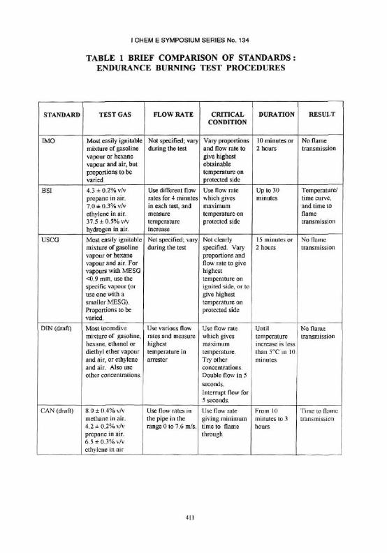
Table 1 summarises current test procedures for endurance burning. Only BSI and CAN specify the gas and air mixture proportions to be used throughout the test. In IMO and USCG, the test starts with the most easily ignitable mixture, but the proportions are subsequently required to be varied by the tester. In the DIN procedure, the test is carried out with the most incendive mixture. At the end of the DIN procedure, other concentrations are used.
In the BSI, DIN and CAN procedures, a number of initial tests are carried out with different flow rates, to identify the critical flow rate which is used in the main test. In the DIN draft standard it is pointed out that the critical flow rate (which gives the maximum element temperature) corresponds to a gas velocity through the open area of the element approximately equal to the burning velocity. In the IMO and USCG procedures, the flow rate (and the mixture proportions) are varied during the course of the test, in order to achieve the highest element temperature.
406
I CHEM E SYMPOSIUM SERIES No. 134
The arrester passes the IMO, USCG or DIN test, if no flame transmission occurs for a specified duration, (between approximately 10 minutes and 2 hours). In the BSI and CAN test, the result is the time to flame transmission, and this information may be used in the design of shut-down arrangements in an industrial system.
Our experience gained in carrying out endurance burning testing at Buxton to the IMO and USCG procedures in particular, confirms that they are difficult to interpret. Repeatability between different testing laboratories, and equitable assessment of the performance of arresters, is hard to achieve.
Here we present further results of an experimental programme, in order to provide information to enable better procedures to be written.
APPARATUS AND EXPERIMENTS WITH HEXANE VAPOUR AND AIR
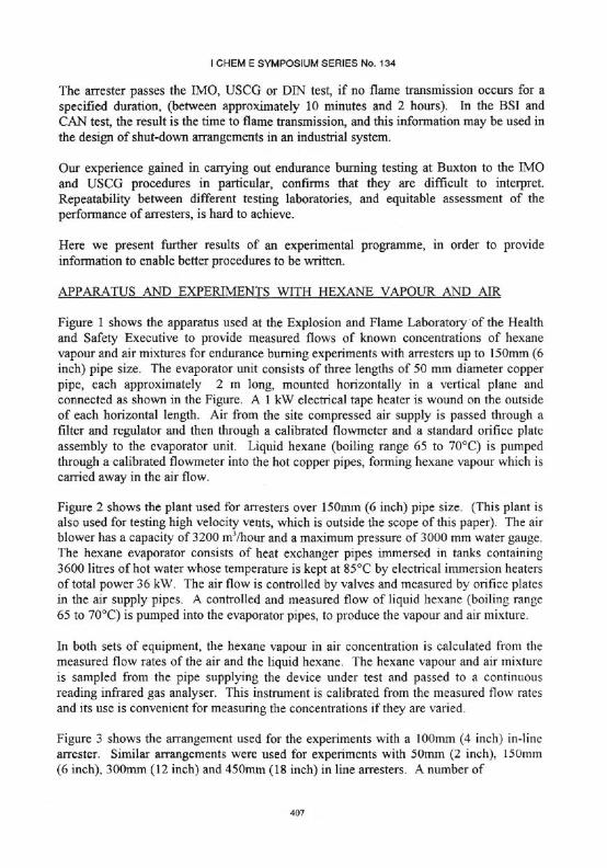
Figure 1 shows the apparatus used at the Explosion and Flame Laboratory of the Health and Safety Executive to provide measured flows of known concentrations of hexane vapour and air mixtures for endurance burning experiments with arresters up to 150mm (6 inch) pipe size. The evaporator unit consists of three lengths of 50 mm diameter copper pipe, each approximately 2 m long, mounted horizontally in a vertical plane and connected as shown in the Figure. A 1 kW electrical tape heater is wound on the outside of each horizontal length. Air from the site compressed air supply is passed through a filter and regulator and then through a calibrated flowmeter and a standard orifice plate assembly to the evaporator unit. Liquid hexane (boiling range 65 to 70°C) is pumped through a calibrated flowmeter into the hot copper pipes, forming hexane vapour which is carried away in the air flow.
Figure 2 shows the plant used for arresters over 150mm (6 inch) pipe size. (This plant is also used for testing high velocity vents, which is outside the scope of this paper). The air blower has a capacity of 3200 mVhour and a maximum pressure of 3000 mm water gauge. The hexane evaporator consists of heat exchanger pipes immersed in tanks containing 3600 litres of hot water whose temperature is kept at 85°C by electrical immersion heaters of total power 36 kW. The air flow is controlled by valves and measured by orifice plates in the air supply pipes. A controlled and measured flow of liquid hexane (boiling range 65 to 70°C) is pumped into the evaporator pipes, to produce the vapour and air mixture.
In both sets of equipment, the hexane vapour in air concentration is calculated from the measured flow rates of the air and the liquid hexane. The hexane vapour and air mixture is sampled from the pipe supplying the device under test and passed to a continuous reading infrared gas analyser. This instrument is calibrated from the measured flow rates and its use is convenient for measuring the concentrations if they are varied.
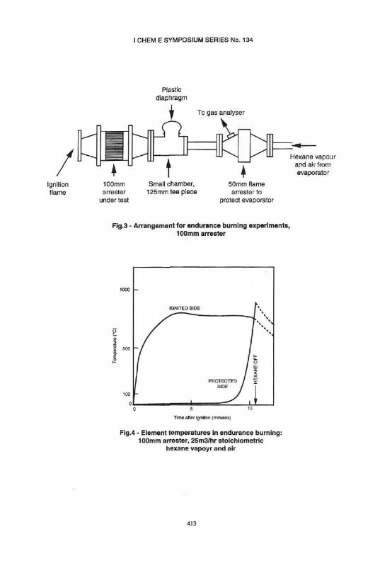
Figure 3 shows the arrangement used for the experiments with a 100mm (4 inch) in-line arrester. Similar arrangements were used for experiments with 50mm (2 inch), 150mm (6 inch), 300mm (12 inch) and 450mm (18 inch) in line arresters. A number of
407

I CHEM E SYMPOSIUM SERIES No. 134
manufacturers supplied the arresters, and some manufacturers supplied a number of arresters. The results of the experiments are not associated with any individual manufacturer. The arrester was placed with its axis horizontal. The arrester flange on the protected side was connected to a tee piece comprising a small chamber. The side arm of the tee was closed by a thin plastic diaphragm. Flame passing through the arrester would cause an explosion in the tee and rupture of the diaphragm. The hexane vapour and air was supplied from the evaporator through another in line arrester which protected the evaporator unit.
Thermocouples were positioned one each side of the crimped ribbon element, half way between the centre and circumference, generally on a radius 45° to the vertical (the radial position was not critical). The crimps were separated slightly and the tip of the thermocouple was inserted 10mm below the surface of the element, to give good thermal contact. The thermocouple temperatures were recorded at 1 minute intervals.
The mixture was ignited by a pilot flame on the downstream side of the element. A stable flame formed on the surface of the element and during the course of the endurance burning the flame withdrew into the element. Figure 4 shows an example of the element temperature-time curves for one experiment with the 100mm (4 inch) arrester, with a stoichiometric mixture of hexane vapour and air (2.16% v/v) of flow rate 25m3/hr. In this experiment the ignited side temperature achieved a maximum of 800°C 4 minutes after ignition, and then decreased slightly as the flame moved through the element. The temperature of the protected side increased rapidly 8 or 9 minutes after ignition in this case.
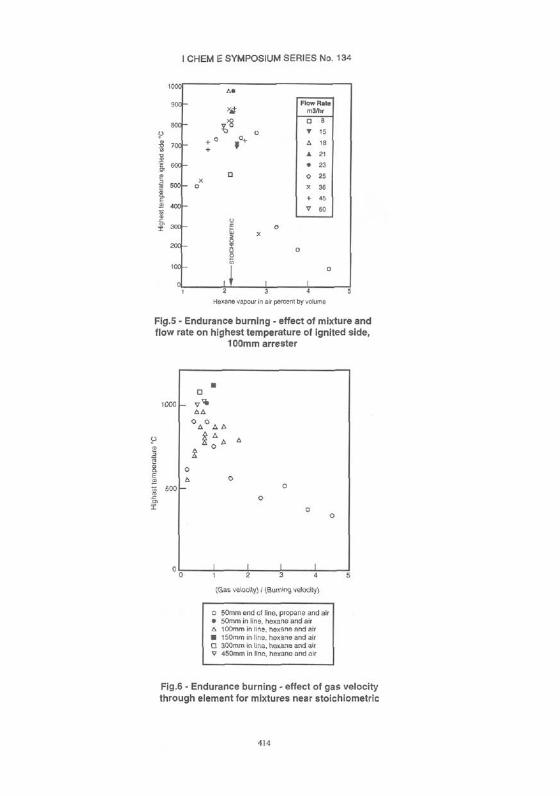
Figure 5 summarises the results of 27 endurance burning experiments with the 100mm (4 inch) arrester. In each of these experiments, the flow rate and hexane vapour in air concentration were kept constant. The results show that the highest temperatures of the ignited side attained a prominent maximum value when the mixture was close to stoichiometric.
Figure 6 shows the effect of the gas velocity through the element (calculated by dividing the volume flow rate by the open area of the element) normalised to the burning velocity, on the highest temperature. These results were obtained with arresters in the size range 50mm (2 inch) to 300mm (18 inch), as shown on the Figure, and with mixtures close to stoichiometric (hexane vapour in air from 2.0 to 2.3% v/v: propane in air from 4.0 to 4.4% v/v). The results for propane were taken from Capp (1992). These results indicate that the highest temperatures occur when the mean gas velocity through the element apertures lies between approximately 0.5 and 1.0 times the burning velocity. (The value 0.4 m/sec was used for the room temperature burning velocity of a stoichiometric mixture of hexane vapour or propane and air). There is scatter in the results, particularly for the higher temperatures. Internal thermal distortion of the element close to the reaction zone would change the open area from the room temperature value assumed, and this distortion is unlikely to be the same in the different experiments with the same element.
408
I CHEM E SYMPOSIUM SERIES No. 134
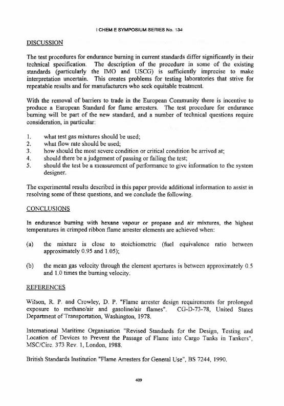
DISCUSSION
The test procedures for endurance burning in current standards differ significantly in their technical specification. The description of the procedure in some of the existing standards (particularly the IMO and USCG) is sufficiently imprecise to make interpretation uncertain. This creates problems for testing laboratories that strive for repeatable results and for manufacturers who seek equitable treatment.
With the removal of barriers to trade in the European Community there is incentive to produce a European Standard for flame arresters. The test procedure for endurance burning will be part of the new standard, and a number of technical questions require consideration, in particular:
1. what test gas mixtures should be used; 2. what flow rate should be used; 3. how should the most severe condition or critical condition be arrived at; 4. should there be a judgement of passing or failing the test; 5. should the test be a measurement of performance to give information to the system
designer.
The experimental results described in this paper provide additional information to assist in resolving some of these questions, and we conclude the following.
CONCLUSIONS
In endurance burning with hexane vapour or propane and air mixtures, the highest temperatures in crimped ribbon flame arrester elements are achieved when:
(a) the mixture is close to stoichiometric (fuel equivalence ratio between approximately 0.95 and 1.05);
(b) the mean gas velocity through the element apertures is between approximately 0.5 and 1.0 times the burning velocity.
REFERENCES
Wilson, R. P. and Crowley, D. P. "Flame arrester design requirements for prolonged exposure to methane/air and gasoline/air flames". CG-D-73-78, United States Department of Transportation, Washington, 1978.
International Maritime Organisation "Revised Standards for the Design, Testing and Location of Devices to Prevent the Passage of Flame into Cargo Tanks in Tankers", MSC/Circ. 373 Rev. 1, London, 1988.
British Standards Institution "Flame Arresters for General Use", BS 7244, 1990.
409
I CHEM E SYMPOSIUM SERIES No. 134
United States Department of Transportation, Coast Guard, Federal Register, "Marine Vapor Control Systems: Final Rule", 55 (120), 25396, 1990.
Deutsches Institut fur Normung, DIN Draft Standard, "Flame arresting devices", 1991.
Capp, B. "Temperature rise of a rigid element flame arrester in endurance burning with propane," J.Loss Prev. Process Ind, 5, 215, 1992.
Dainty, E. E. and Lobay, G. "An Investigation of Flame Arrester Continuous Burn Test Protocols", MRL 91-136 (TR), CANMET, Ottawa, 1992.
Canadian Standards Association, Draft, "Test Methods for In-Line and Firebox Flame Arresters", CAN/CSA-Z343, 1992.
410
I CHEM E SYMPOSIUM SERIES No. 134
TABLE 1 BRIEF COMPARISON OF STANDARDS : ENDURANCE BURNING TEST PROCEDURES
STANDARD
IMO
BSI
USCG
DIN (draft)
CAN (draft)
TEST GAS
Most easily ignitable mixture of gasoline vapour or hexane vapour and air, but proportions to be varied
4.3 ±0.2% v/v propane in air. 7.0 ±0 .3% v/v ethylene in air. 37.5 ± 0.5% v/v hydrogen in air.
Most easily ignitable mixture of gasoline vapour or hexane vapour and air. For vapours with MESG <0.9 mm, use the specific vapour (or use one with a smaller MESG). Proportions to be varied.
Most incendive mixture of gasoline, hexane. ethanol or diethyl ether vapour and air, or ethylene and air. Also use other concentrations.
8.0 ± 0.4% v/v methane in air. 4.2 ± 0.2% v/v propane in air. 6.5 ±0 .3% v/v ethylene in air
FLOW RATE
Not specified; vary during the test
Use different flow rates for 4 minutes in each test, and measure temperature increase
Not specified: vary during the test
Use various flow rates and measure highest temperature in arrester
Use flow rates in the pipe in the range 0 to 7.6 m/s.
CRITICAL CONDITION
Vary proportions and flow rate to give highest obtainable temperature on protected side
Use flow rate which gives maximum temperature on protected side
Not clearly specified. Vary proportions and flow rate to give highest temperature on ignited side, or to give highest temperature on protected side
Use flow rate which gives maximum temperature. Try other concentrations. Double flow in 5 seconds.
Interrupt flow for 5 seconds.
Use flow rate giving minimum time to flame through
DURATION
10 minutes or 2 hours
Up to 30 minutes
15 minutes or 2 hours
Until temperature increase is less than 5°C in 10 minutes
From 10 minutes to 3 hours
RESULT
No flame transmission
Temperature/ time curve, and time to flame transmission
No flame transmission
No flame transmission
Time to flame transmission
411

I CHEM E SYMPOSIUM SERIES No. 134
Fig.2 - Endurance burning test equipment for flame arresters over 150mm pipe size and for high velocity vents
412
I CHEM E SYMPOSIUM SERIES No. 134
4 ! 3
I CHEM E SYMPOSIUM SERIES No. 134
414