Flamco Pipe Support System - easyFairs
64
Flamco Pipe Support System
Transcript of Flamco Pipe Support System - easyFairs

FlamcoPipe Support System
63025 Flamco Cover 2007 3/7/07 16:30 Page 1

Flamco Index
General introduction to the Boss Flamco Pipe Support System 4A pictorial description of the range of Pipe Hangers, Wall Clips and accessories available 6Assemblies recommended when using BK BKI and BKK Pipe Hangers 8
BK 10BSF 12BSFD 13BSO 14BM 15BW 16
BKK 17BMK 18
BKI 19BSA 21BSA 1/2 in 23BSB 24
BSA-G 25
BKS 26
Koolphen 27Woodblock 28Vermiculite 29
Flamco Rail 30HS1 Cantilever Set 32HS2 Angleplate & HS3 Cantilever 33Rail Consoles 34KC & KCK Girder Clamps 35RB Girder Clips 36PS, RH & RL Rail Connections 37RZ–V & RZ–H Rail Support Saddles 38KF–V & KF–H Rail Support Flanges 39HA Height Adjusters 40RD Rail End Caps 41
Threaded Rod 42Threaded Rod Ends 42T Caps for BK Brackets 43BO/BOK Extension Pieces for BK brackets 44Nuts/Washers/Rail Clamps 45M & HB Support Nuts 46KSM Connectors 47Woodscrews and Installation Tools 48GP Backplates/AD Adaptors 49BMD Backplates 50BME Backplates 51
BOSS Springhangers 52
K & KK Ball Hangers 53GK Expansion Units 54DA Noise Suppression Fixtures 56SR Noise Suppression Strips 57
Rail Specifications and Selection Information 58Installation Dimensions 60T-Plus Branch Connections 62
Pipe Hanger Range for Steel
Pipe Hanger Range for Copper
Pipe Hanger Range for Steel/Copper
Pipe Hanger Range for PlasticPipe Hanger Range for Sprinkler Systems
Pipe Support Insulation Blocks
Rail and Framing Accessories
Threaded Rod and Accessories
Branch Connector
Expansion and Anti-Vibration
Technical Information
INDEX PAGES
2
63025 Flamco Cover 2007 3/7/07 16:30 Page 2
creo

Flamco Pipe Support System
This catalogue features the range of Boss Flamco Pipe Clips and Accessories available throughBSS (UK) branch office warehouses. The various assemblies which can be made up are fullyillustrated to enable customers to select the assembly most suitable for their particular applica-tions.The system is designed and manufactured by Flamco BV, Gouda, Holland.
APPLICATION & PROTECTION
The Flamco Pipe Support System is for use in supporting horizontal and vertical heating and airconditioning pipework within buildings. The thickness of zinc coating on Flamco Pipe SupportSystem components is sufficient to protect them prior to installation and for use without furtherprotection where dry uncontaminated conditions can be guaranteed. All components should bestored as delivered, under cover, in dry conditions.Further protection should be provided where moist conditions may prevail or where fit-tings may not be easily accessible for regular inspection.Frequency depends on environmental conditions.The BSS (UK) system of branch offices covers the whole of the UK and Eire with a network ofwell-stocked warehouses to meet the demands of the heating engineer and industrial user.Each branch office has a trained sales and technical staff, both internal and external, who will bepleased to advise you on any heating or pipeline problem.The products supplied by BSS (UK) are generally in accordance with British or other Internation-al Standard Specifications where applicable and as interpreted by the manufacturers, and pre-sent no hazard to health or safety if properly installed and operated.There are, however, many occasions when goods are ordered from us without any referencebeing made to their intended use, in which case, the Company must assume that users will takeall necessary steps to ensure that the products purchased are suitable for the conditions inwhich they are intended to operate.Our current catalogues generally indicate the Standards and Classes with which the productscomply, but if in doubt, please consult your nearest BSS (UK) Branch.
• QUICK AND EASY TO INSTALLSaves time and money• VERSATILEThe system offers many combinations• FLEXIBLEAllows for limited pipe movement• ADJUSTABLEAllows for pipe falls and level changes
Copyright : The drawings and illustrations featured in this catalogue are subject to copyright and must not be reproducedwithout written permission of the Company.
• EASILY MODIFIEDMakes pipeline alterations easy• CORROSION RESISTANTMost items zinc coated as standard• NOISE REDUCTIONThe design of certain products helps toreduce pipeline noise• BBA APPROVEDProducts are independently tested to ensurequality and strength
BOSS FLAMCO IS THE EASY AND SIMPLE TO USE PIPE SUPPORT SYSTEM
The main advantages gained by using the BOSS FLAMCO pipe support system are:
3
flamco 64pp 01/12/03 12:17 pm Page 3

Flamco Pipe Support System – Introduction
The resulting installation is quick, strong, secure, flexible and neat.
TYPICAL METHOD OF INSTALLING A PIPE HANGER TO BOSS FLAMCO RAIL
Secure rod to the fix-ing point
Screw and tighten theball head onto thethreaded rod securely
Fit the clip around thepipe
Press clip jaws aroundthe ball head
Pull sleeve and captheir full distancedown over clip jaws
TYPICAL METHOD OF INSTALLING BOSS FLAMCO WALL CLIP
Drill wall and insert thewall plug
Fit locknut and screwin woodscrew usingdrive cap
Remove the drive capand push on the collar
Fit clip around thepipe
Close clip and pushon collar
Tighten the locknutagainst the collar
THE BASIC HANGERASSEMBLY
THE BASIC WALL CLIPASSEMBLY
PVC ‘T’ CAP3 STANDARD
SIZES
THREADEDROD
SLEEVE
CLIP
THREADEDBALL HEAD
A FULL RANGE OFSIZES TO FIT ALL
APPLICATIONS AREAVAILABLE
WOODSCREW
LOCKNUT
CLIP
COLLAR
Fit ‘T’ cap onto rod andpush sleeve into it
...BOSS FLAMCO IS THE EASY AND SIMPLE TO USE PIPE
SUPPORT SYSTEM
1 2 3
4 5 6
1 2 3
4 5 6
JOGGLE
4
flamco 64pp 01/12/03 12:17 pm Page 4

...IDEAL FOR ALL OVERHEAD MOUNTING
APPLICATIONS
The system has been designed to suit most overhead hanging require-ments – from a simple run along a concrete ceiling to a multiple hangingrequirement. Whichever application suits your requirement you will findthe system easy to understand and install.The basic system can also be added to by the use of the many special-ist items, such as noise suppression fixtures, expansion units etc. Andremember all this is backed up by the technical expertise offered at allBSS (UK) branches.
...IDEAL FOR ALL WALL
MOUNTING APPLICATIONS
The wall system is equally adaptable whenmounting pipes up or along a wall. Therange starts with the simple BM clipswhich are attached by the woodscrew andplug system right up to the multi hangingcantilever sets.
Flamco Pipe Support System – Introduction
5
flamco 64pp 01/12/03 12:17 pm Page 5

Flamco Hangers, Wall Clips and Accessories
Pipe Hangers And Wall Clips
Koolphen InsulationBlock Applications
Steel TubeApplications
Copper TubeApplications
Plastic TubeApplications
Wooden InsulatedApplications
VermiculiteInsulated Applications
Sprinkler Systems
Steel or CopperApplications
BK3/8in N.B. to 6in N.B.BS1387 steel tube(larger sizes available)
BKIAs BK but with noise suppressionrubbers. 3/8in N.B. to 6in N.B.BS1387 steel tube 12mm to 54mm BS2871 table 'X'
BKWith Phenolic inserts (available15–50mm thick) 1/2in N.B. to 6in N.B. BS1387 steel tube 15mm to 159mm copper tube BS2871 table 'X'(other sizes available)
BSF1/2in N.B. to 4in N.B. BS1387 steel tube 15mm to 76mm copper tubeBS2871 table 'X'Insulation 15mm to 50mm thick
BK or BSF with wood inserts(approx 20mm to 65mm thick)1/2in N.B. to 6in N.B. BS1387 steel tube 15mm to 159mm copper tube BS2871 table 'X'
BK or BSF with Vermiculite inserts.Steel spreader plates also available
BKK12mm to 159mm BS2871 copper tube table 'X'
BMK12mm to 54mm BS2871 copper tube table 'X'
BM3/8in N.B. to 4in N.B.BS1387 steel tube
BSA1/2in N.B. to 6in N.B. BS1387 steel tube 15mm to 159mm BS2871 table 'X'
BSA 1/2in(Single or Two Screw)3/8in N.B. to 4in N.B. BS1387 steel tube
BSB3/8in N.B. to 2in N.B. BS1387 steel tube15mm to 54mmBS2871 copper tube table 'X'
BSF1/2in N.B. to 6in N.B.BS1387 steel tube
BSA-G1/2in N.B. to 4in N.B.includes flat rubber and spacer
BKS1/2in to 8in pipe sizesBSO
2in N.B. to 6in N.B.BS1387 steel tube(larger sizes available)
see page 10
see page 15
see page 12
see page 14
see page 17
see page 18
see page 25
see page 26
see page 19
see page 21
see page 23
see page 24
see page 27
see page 27
see page 28
see page 29
6
flamco 64pp 01/12/03 12:17 pm Page 6

ROZinccoated2mlengths18x28mm
R1Zinccoated2mlengths15x30mm
R2Zinccoated2mlengths20x34mm
R3Zinccoated2mlengths40x34mm
R4Zinccoated4mlengths46x35mm
R6Zinccoated2mlengths60x41mm
RBGirder Clips for R1, R2, R4and R6 rail
RZ-VRZ-HSupportSaddles
KF-VKF-HSupportFlanges
Rail ConnectionsRH90RH90E
HBSHammerheadnut setsM8M10
HAHeight adjusters M8, M10and M12
'T' CapsTo be used with BK, BKI,BKK, T6, T8 and T12
RodM6, M8, M10 and M121, 2 or 3 metre lengths
BMD/BMEBackplate Assembly
BO + BOKExtension Piecesfor use with BK, BKK & BKI
DANoise Suppression Mounts
GKRange of Expansion Units
GPBackplateM8M8/M10M121/2" BSP
AD Adaptor
M8 x 1/2
M10 x 1/2
T+ PercussionTees
1/2 x 1/2 21/2 x 11/43/4 x 1/2 3 x 11/4
1 x 3/4 15 x 1511/4 x 1 28 x 1/2
11/2 x 11/4 28 x 3/4
2 x 11/4 35 x 3/4
NoiseSuppressionStrips
KCK + KCGirder ClampsM6, M8, M10 & M12
Ball HangersM6, M8, M10 and M12
KSM Connectors
HO WoodscrewsM8, M10 and M12
Rail End CapsRD1, RD2, RD4, RD6
Rail ConsolesR1, R2 and R4
HS2Angle Plate
HS3Cantilever Bracket
HS1Cantilever Set
For use with R1 or R2 rail
Washers
Nuts
SP or SPSR railclampfor R4 and R6 rail
Rail support nut for rail
Hammerhead nutfor rail
For any other pipebracket requirementseg. slide guides, rollerand chairs, spring hang-ers etc. contact yourlocal BSS (UK) branch
see page 30–31
see page 36
see page 32see page 33
see page 33
see page 34
see page 41
see page 37
see page 39
see page 38
see page 45–46
see page 46
see page 40
see page 43
see page 54 – 55
see page 56
see page 50–51
see page 53
see page 48
see page 42 see page 49
see page 49
see page 47
see page 44
see page 57
see page 62
see page 35
Rail Framing Ancillary Items
7
flamco 64pp 01/12/03 12:17 pm Page 7

BK 6 T6 D6G M6 S6s M6s SP6 SP6SR
BKI 6 T6 D6G M6 S6s M6s SP6 SP6SR
BKK 6 T6 D6G M6 S6s M6s SP6 SP6SR
BK 8 T8 D8G M8 S8s M8s SP8 SP8SR
BKI 8 T8 D8G M8 S8s M8s SP8 SP8SR
BKK 8 T8 D8G M8 S8s M8s SP8 SP8SR
BK 12 T12 D12G M12 S12 M12s SP12 SP12SR
BKI 12 T12 D12G M12 S12 M12s SP12 SP12SR
BKK 12 T12 D12G M12 S12 M12s SP12 SP12SR
BK 6 T6 D6G M6 K10 x 6
BKI 6 T6 D6G M6 K10 x 6
BKK6 6 T6 D6G M6 K10 x 6
BK 8 T8 D8G M8 K10 x 8
BKI 8 T8 D8G M8 K10 x 8
BKK 8 T8 D8G M8 K10 x 8
BK 6 T6 D6G 2 x M6
BKI 6 T6 D6G 2 x M6
BKK 6 T6 D6G 2 x M6
BK 8 T8 D8G 2 x M8
BKI 8 T8 D8G 2 x M8
BKK 8 T8 D8G 2 x M8
BK 12 T12 D12G 2 x M12
BKI 12 T12 D12G 2 x M12
BKK 12 T12 D12G 2 x M12
Flamco BK, BKI and BKK Hanger Assemblies
The ball head of BK pipe hangers gives an axial movement of up to 12˚ (2 x 6˚).This axial movement ensures that the assembly is not distorted or damaged as thepipe expands because of temperature changes.The length of the sleeve is such that, even after the assembly is fitted, it is still pos-sible to insulate the pipe without affecting the movement of the ball element.Pipes can be installed one below the other without difficulty. BK pipe hangers havea joggle at the bottom of the clip to accommodate a BO or BOK extension piece. See page 44
TYPE ‘B1’
Assembly with threaded rod and male ball hanger
TYPE ‘C1’
Assembly with threaded rod to rail
COMPONENTS REQUIRED
FOR TYPE ‘A1’ ASSEMBLIES
COMPONENTS REQUIRED
FOR TYPE ‘B1’ ASSEMBLIES
COMPONENTS REQUIRED
FOR TYPE ‘C1’ ASSEMBLIES
Hanger Ref.
CapThreaded
RodBackNut
Hanger Ref.
CapThreaded
RodBackNut
BallHanger
Hanger Ref.
CapThreaded
RodBackNut
RailWasher
RailSupport
Nut
RailClamp
RailClamp
GENERAL INFORMATION
All of the BK, BKI and BKK range ofpipe hangers consist of
• Ball head• Sleeve• One-piece bracket
M6M8M12
M6M8
M6sM8sM12sS6s
S8sS12
M6M8M12
M6M8M12
RO,R1 or R2 Rail
IMPORTANTWhen using R4 railUse SP6, SP8 or SP12rail clampDo not useS6s, S8s or S12 wash-er
IMPORTANTWhen using R6 railUse SP6SR, SP8SR orSP12SR rail clampDo not useS6s, S8s or S12 wash-er
R4 Rail + R6 Rail
M6s, M8s, M12s
TYPE ‘A1’
Assembly with threaded rod
R0, R1or R2Rail
R4 Rail R6 RailR0, R1,R2, R4 orR6 Rail
8
flamco 64pp 01/12/03 12:17 pm Page 8

NOTE: • All items are supplied as separate components and are not pre-assembled.• Rod is supplied in 1m, 2m or 3m lengths.• The rail type for your application should be chosen using the information on pages 58 & 59 or contact your local
BSS (UK) Branch for rail sizing.• R0, R1, R2, R6 supplied in 2m lengths.• R4 supplied in 4m lengths.
BK 6 T6 D6G M6 K6x6 S6s HB6 SP6 SP6SR
BKI 6 T6 D6G M6 K6x6 S6s HB6 SP6 SP6SR
BKK 6 T6 D6G M6 K6x6 S6s HB6 SP6 SP6SR
BK 8 T8 D8G M8 K8x8 S8s HB8 SP8 SP8SR
BKI 8 T8 D8G M8 K8x8 S8s HB8 SP8 SP8SR
BKK 8 T8 D8G M8 K8x8 S8s HB8 SP8 SP8SR
BK 12 T12 D12G M12 K12x12 S12 HB12 SP12 SP12SR
BKI 12 T12 D12G M12 K12x12 S12 HB12 SP12 SP12SR
BKK 12 T12 D12G M12 K12x12 S12 HB12 SP12 SP12SR
BK 6 T6 D6G M6 K10x6 M10 S10s M10s SP10 SP10SR
BKI 6 T6 D6G M6 K10x6 M10 S10s M10s SP10 SP10SR
BKK 6 T6 D6G M6 K10x6 M10 S10s M10s SP10 SP10SR
BK 8 T8 D8G M8 K10x8 M10 S10s M10s SP10 SP10SR
BKI 8 T8 D8G M8 K10x8 M10 S10s M10s SP10 SP10SR
BKK 8 T8 D8G M8 K10x8 M10 S10s M10s SP10 SP10SR
Hanger
Ref.Cap
Threaded
Rod
Back
Nut
Ball
Hanger
Hanger
Ref.Cap
Thread-
ed Rod
Back
Nut
Ball
Hanger
Back
Nut
Hammer
Head Nut
Rail
Washer
R0, R1or R2Rail
R4 Rail R6 RailR0, R1,R2, R4 orR6 Rail
R0,R1or R2Rail
R4 Rail R6 RailR0,R1,R2, R4 or R6Rail
Rail
Clamp
Rail
Clamp
Rail
Support
Nut
Rail
Clamp
Rail
Clamp
Rail
Washer
TYPE ‘D1’
Assembly with rail using female ball hangers
TYPE ‘E1’
Assembly with rail using male ball hangers
COMPONENTS REQUIRED
FOR TYPE ‘D1’ ASSEMBLIES
COMPONENTS REQUIRED
FOR TYPE ‘E1’ ASSEMBLIES
HB6HB8HB12
S6sS8sS12
HB6HB8HB12
M10s
M10h
M10s
M10
S10s
RO,R1 or R2 Rail
IMPORTANTWhen using R4 railUse SP6, SP8 or SP12rail clampDo not useS6s, S8s or S12 wash-er
IMPORTANTWhen using R4 railUse SP10 rail clampDo not useS12 washer
R4 Rail RO,R1 or R2 Rail R4 Rail and R6 rail
IMPORTANTWhen using R6 railUse SP6SR, SP8SR orSP12SR rail clampDo not useS6s, S8s or S12 washer
M6M8
M6M8 M6
M8
9
Flamco BK, BKI and BKK Hanger Assemblies
flamco 64pp 01/12/03 12:19 pm Page 9

Flamco BK Pipe Hangers
The hanger is used for installing steel tube horizontally.The hanger comprises three components and is supplied as a complete assembly in alarge variety of sizes.
CONSTRUCTION AND COATINGS
• bracket BK6 zinc coated material (Sendzimir)• bracket BK8 zinc coated material (Sendzimir)• bracket BK12 electrolytically zinc-plated• sleeve electrolytically zinc-plated• ball head electrolytically zinc-plated
FEATURES
• max. swing of the pipe hanger 2 x 6˚• BK12 sleeve with locking system• temperature range –20˚ to +120˚C
For installation dimensions see page 60NOTE 1: Should be installed with a 'T' cap see page 43NOTE 2: Technical advice should be sought for use on steam lines
Typicalinstallationto Flamcorail
Ball head
Sleeve
One piecebracket
Joggle
BK6BK8
BK12
for steel tube
(BBA Approved)
10
flamco 64pp 01/12/03 12:19 pm Page 10

Flamco BK Pipe Hangers size range
BK 6 x 3/8" 3/8 17.2 17.7 M6 1500 12 x 1.5 40BK 6 x 1/2" 1/2 21.3 21.8 M6 1500 12 x 1.5 40BK 6 x 3/4" 3/4 26.9 27.4 M6 1500 12 x 1.5 40BK 6 x 1 1 33.7 34.2 M6 1500 12 x 1.5 40BK 6 x 44 11/4 42.4 45.0 M6 1500 12 x 1.5 40BK 6 x 51 11/2 48.3 51.5 M6 1500 12 x 1.5 40BK 6 x 62 2 60.3 62.0 M6 1500 12 x 1.5 40BK 8 x 78 21/2 76.1 78.8 M8 2500 16 x 1.9 54BK 8 x 90 3 88.9 90.9 M8 2500 16 x 1.9 54BK 12 x 121 4 114.3 122.2 M12 5000 25 x 2.75 60BK 12 x 146 5 139.7 147.5 M12 5000 25 x 2.75 60BK 12 x 171 6 165.1 172.7 M12 5000 25 x 2.75 60
BK 6 x 38 38.5 M6 1500 12 x 1.5 40BK 6 x 44 45.0 M6 1500 12 x 1.5 40BK 6 x 51 51.5 M6 1500 12 x 1.5 40BK 6 x 57 57.6 M6 1500 12 x 1.5 40BK 6 x 62 62.0 M6 1500 12 x 1.5 40BK 6 x 64 64.1 M6 1500 12 x 1.5 40
BK 8 x 68 68.5 M8 2500 16 x 1.9 54BK 8 x 70 70.7 M8 2500 16 x 1.9 54BK 8 x 74 74.5 M8 2500 16 x 1.9 54BK 8 x 76 76.9 M8 2500 16 x 1.9 54BK 8 x 78 78.8 M8 2500 16 x 1.9 54BK 8 x 83 83.3 M8 2500 16 x 1.9 54BK 8 x 87 87.5 M8 2500 16 x 1.9 54BK 8 x 89 89.8 M8 2500 16 x 1.9 54BK 8 x 90 90.9 M8 2500 16 x 1.9 54BK 8 x 95 96.0 M8 2500 16 x 1.9 54BK 8 x 98 98.5 M8 2500 16 x 1.9 54BK 8 x 10² 102.6 M8 2500 16 x 1.9 54
BK 12 x 105 105.5 M12 5000 25 x 2.75 60BK 12 x 108 109.1 M12 5000 25 x 2.75 60BK 12 x 113 113.5 M12 5000 25 x 2.75 60BK 12 x 114 115.4 M12 5000 25 x 2.75 60BK 12 x 121 122.2 M12 5000 25 x 2.75 60BK 12 x 125 125.5 M12 5000 25 x 2.75 60BK 12 x 127 128.3 M12 5000 25 x 2.75 60BK 12 x 133 134.3 M12 5000 25 x 2.75 60BK 12 x 137 137.5 M12 5000 25 x 2.75 60BK 12 x 140 141.1 M12 5000 25 x 2.75 60BK 12 x 144 144.5 M12 5000 25 x 2.75 60BK 12 x 146 147.5 M12 5000 25 x 2.75 60BK 12 x 152 153.9 M12 5000 25 x 2.75 60BK 12 x 159 160.6 M12 5000 25 x 2.75 60BK 12 x 165 165.5 M12 5000 25 x 2.75 60BK 12 x 168 170.0 M12 5000 25 x 2.75 60BK 12 x 171 172.7 M12 5000 25 x 2.75 60BK 12 x 178 179.6 M12 5000 25 x 2.75 60BK 12 x 185 185.5 M12 5000 25 x 2.75 60BK 12 x 193 195.6 M12 5000 25 x 2.75 60BK 12 x 199 199.5 M12 5000 25 x 2.75 60BK 12 x 205 205.5 M12 5000 25 x 2.75 60BK 12 x 216 218.2 M12 5000 25 x 2.75 60BK 12 x 219 221.3 M12 5000 25 x 2.75 60BK 12 x 225 225.5 M12 5000 25 x 2.75 60BK 12 x 231 231.5 M12 5000 25 x 2.75 60BK 12 x 241 243.4 M12 5000 25 x 2.75 60BK 12 x 251 251.5 M12 5000 25 x 2.75 60BK 12 x 267 269.7 M12 5000 25 x 2.75 60BK 12 x 273 275.7 M12 5000 25 x 2.75 60BK 12 x 299 301.5 M12 5000 25 x 2.75 60BK 12 x 323 327.1 M12 5000 25 x 2.75 60
* This hanger has no joggle
Hanger Reference
BS 1387Steel Tube
NBinch
Approxo/d mm
Clipl/d
mmThread
Maximumworkingload N
Clipmaterialwidth x
thickness mm
Dim‘A’
mm
HANGERS
FOR USE
WITH
BS 1387
STEEL TUBE
FULL RANGE
OF BK
PIPE HANGERS
*
11
flamco 64pp 01/12/03 12:19 pm Page 11

Flamco BSF Clips
Suitable for steel tubes which have to be fitted close to ceilings and walls.The range includes sizes to accommodate insulation blocks for 1/2in to 4in, N.B. BS1387 steel tube (15mm-50mm thick) and 15mm-76mm BS 2871 Table ‘X’ coppertube (15mm-50mm thick).
FEATURES• connection sizes M8, M10 or M12 according to size of clip• certain smaller sizes are available with either M8 or M10 connections• temperature rating: -20° to +120°C• Screws supplied with retaining washers
COATING• electrolytically zinc-plated
BSF 8 x 21-25.5 21-25.5 4.5 M8 1000 20 x 2.5 M6 x 20 1/2 21.3
BSF 8 x 26.5-30.5 26.5-30.5 4.0 M8 1000 20 x 2.5 M6 x 20 3/4 26.9
BSF 8 x 33.5-38.5 33.5-38.5 5.0 M8 1000 20 x 2.5 M6 x 20 1 33.7
BSF 8 x 41.5-47 41.5-47 5.5 M8 1000 20 x 2.5 M6 x 20 11/4 42.4
BSF 8 x 48-54 48-54 6.0 M8 1000 20 x 2.5 M6 x 20 11/2 48.3
BSF 8 x 56-62.5 56-62.5 6.5 M8 1000 20 x 2.5 M6 x 20 2 60.3
BSF 10 x 21-25.5 21-25.5 4.5 M10 1000 20 x 2.5 M6 x 20 1/2 21.3
BSF 10 x 26.5-30.5 26.5-30.5 4.0 M10 1000 20 x 2.5 M6 x 20 3/4 26.9
BSF 10 x 33.5-38.5 33.5-38.5 5.0 M10 1000 20 x 2.5 M6 x 20 1 33.7
BSF 10 x 41.5-47 41.5-47 5.5 M10 1000 20 x 2.5 M6 x 20 11/4 42.4
BSF 10 x 48-54 48-54 6.0 M10 1000 20 x 2.5 M6 x 20 11/2 48.3
BSF 10 x 56-62.5 56-62.5 6.5 M10 1000 20 x 2.5 M6 x 20 2 60.3
BSF 10 x 62.5-69.5 62.5-69.5 7.0 M10 1000 20 x 2.5 M6 x 20
BSF 10 x 69.5-76.5 69.5-76.5 7.0 M10 1000 20 x 2.5 M6 x 20 21/2 76.1
BSF 10 x 77.5-84 77.5-84 6.5 M10 1000 20 x 2.5 M6 x 20
BSF 10 x 85-92.5 85-92.5 7.5 M10 1000 20 x 2.5 M6 x 20 3 88.9
BSF 12 x 93-100.5 93-100.5 7.5 M12 2000 25 x 2.5 M8 x 25
BSF 12 x 101.5-110 101.5-110 8.5 M12 2000 25 x 2.5 M8 x 25
BSF 12 x 110-117.5 110-117.5 7.5 M12 2000 25 x 2.5 M8 x 25 4 114.3
BSF 12 x 119.5-127.5 119.5-127.5 8.0 M12 2000 25 x 2.5 M8 x 25
BSF 12 x 127.5-133.5 127.5-133.5 6.0 M12 2000 25 x 2.5 M8 x 25
BSF 12 x 134.5-142.5 134.5-142.5 8.0 M12 2500 30 x 3 M8 x 30 5 139.7
BSF 12 x 143.5-150.5 143.5-150.5 7.0 M12 2500 30 x 3 M8 x 30
BSF 12 x 151.5-159.5 151.5-159.5 8.0 M12 2500 30 x 3 M8 x 30
BSF 12 x 163.5-171.5 163.5-171.5 8.0 M12 2500 30 x 3 M8 x 30 6 165.1
BSF 12 x 172.5-182 172.5-182 9.5 M12 2500 30 x 3 M8 x 30
BSF 12 x 192.5-198 192.5-198 5.5 M12 2500 30 x 3 M8 x 30
BSF 12 x 215-220 215-220 5.0 M12 2500 30 x 3 M8 x 30
* The BSF Clip when fitted directly to BS 1387 steel tube will fit tight on to the tube.* Larger sizes available please contact your local BSS (UK) branch
Clip i/dRange mm
Approx.gap mm
NutMax.
workingload
Clip mate-rial width xthickness
mmScrews
NBinch
ApproxO/D mm
*BS 1387Steel Tube
Typicalinstallations Approx
Gap(See table below)
for steel tube
12
ClipReference
flamco 64pp 01/12/03 12:19 pm Page 12

BSFD 10 x 21-25.5 21-25.5 4.5 2 x M10 1000 20 x 2.5 M6 x 20 1/2 21.3
BSFD 10 x 26.5-30.5 26.5-30.5 4.0 2 x M10 1000 20 x 2.5 M6 x 20 3/4 26.9
BSFD 10 x 33.5-38.5 33.5-38.5 5.0 2 x M10 1000 20 x 2.5 M6 x 20 1 33.7
BSFD 10 x 41.5-47 41.5-47 5.5 2 x M10 1000 20 x 2.5 M6 x 20 11/4 42.4
BSFD 10 x 48-54 48-54 6.0 2 x M10 1000 20 x 2.5 M6 x 20 11/2 48.3
BSFD 10 x 56-62.5 56-62.5 6.5 2 x M10 1000 20 x 2.5 M6 x 20 2 60.3
* The BSF Clip when fitted directly to BS 1387 steel tube will fit tight on to the tube.* Larger sizes available please contact your local BSS (UK) branch
FEATURES
• connection sizes, 2 x M10 of clip• temperature rating: -20˚ to +120˚C• Screws supplied with retaining washers
COATING
• electrolytically zinc-plated
ClipReference
Clip i/d Rangemm
Approx.gap mm
NutMax.
workingload
Clip mate-rial widthx thick-
ness mmScrews
NBinch
ApproxO/D mm
*BS 1387Steel Tube
ApproxGap
(See table below)
Typical installations
Flamco BSFD Double
for steel tube
13
flamco 64pp 01/12/03 12:19 pm Page 13

FEATURES
• connection sizes either M10 or M12 using J.B. Hanger
• temperature rating -20° to +120°C• electrolytically zinc-plated
J.B. HANGER
FEATURES
• available M10 or M12• nut incorporated• electrolytically zinc-plated
* larger sizes available please contact your local BSS (UK) branch
BSO 2" BSO 2" 56 - 62.5 1200 20x2.5 M8x25 2 60.3
BSO 21/2" BSO 21/2" 69.5 - 76.5 1200 20x2.5 M8x25 21/2 76.1
BSO 3" BSO 3" 85 - 92.5 1200 20x2.5 M8x25 3 88.9
BSO 4" BSO 4" 110 - 117.5 2000 25x2.5 M10x30 4 114.3
BSO 5" BSO 5" 134.5 - 142.5 4000 30x3 M10x30 5 139.7
BSO 6" BSO 6" 163.5 - 171.5 4080 30x3 M10x30 6 165.1
Clip Ref. Clip BoltsN.B. Inch
*BS 1387 Steel TubeClip I.D. range mm
Max workingload N O/D mm
JB10 M10 M10 6000
JB12 M12 M12 6000
Reference Max working load NConnection size Thread
Flamco BSO Clips
for steel tube
14
flamco 64pp 01/12/03 12:19 pm Page 14

This clip is for mounting steel tube.This clip is supplied as three separate components and can be assembled with otheraccessories to suit your particular requirements as illustrated below.
CONSTRUCTION AND COATINGS
• clip zinc coated material (Sendzimir)• sleeve electrolytically zinc-plated• backnut electrolytically zinc-plated
FEATURES
• one-piece clip held in position by tightening the backnut onto the conical sleeve• conical sleeve with locating edge for good clamping
BM 8 x 3/8" su 3/8 17.2 18.2 M8 10 x 1.2
BM 8 x 1/2" su 1/2 21.3 22.3 M8 10 x 1.2
BM 8 x 3/4" su 3/4 26.9 27.9 M8 10 x 1.2
BM 8 x 1" su 1 33.7 34.7 M8 10 x 1.2
BM 10 x 11/4" su 11/4 42.4 43.4 M10 12 x 1.5
BM 10 x 11/2" su 11/2 48.3 49.3 M10 12 x 1.5
BM 10 x 2" su 2 60.3 61.4 M10 12 x 1.5
BM 12 x 76 su – – 77.4 M12 16 x 1.9
BM 12 x 83 su 21/2 76.1 83.8 M12 16 x 1.9
BM 12 x 89 su 3 88.9 90.3 M12 16 x 1.9
BM 12 x 114 su 4 114.3 115.9 M12 16 x 1.9
THE MAIN METHODS OF FIXING BM WALL CLIPS
ClipReference
Basic Wall Clip (su) NB
inchapprox.o/d mm
Clipinside
dimensionmm
Thread
Clipmaterial
widthx thickness
mm
BS 1387Steel Tube
Wall fixing using a long woodscrewSee page 48 for woodscrew information
Wall fixing using a shortwoodscrew See page 48 forwoodscrew information
Fixing using a backplateRefer to pages 50 and 51 forall types of backplate avail-able
Fixing to Flamco RailRefer to page 45 for nuts,washers and railclamps.Page 42 for threaded rod
Fixing to existing girderRefer to page 45 for nutsand washers. Refer topage 42 for threaded rod
Flamco BM Wall Clips
for steel tube
15
flamco 64pp 01/12/03 12:19 pm Page 15

BW wall clips are designed to support horizontal pipework with nominal bores from1/2in up to and including 2in. The clip comprises two sections, the lower section carry-ing the mounting bracket which can be fixed to the wall by two No. 12 woodscrews.The upper section of the clip can be moved to one side by slackening the lockingscrew to enable the pipe to be placed in the bottom section of the clip. With the pipein situ, refit the upper section of the clip and tighten the locking screw.
BW 1/2" 1/2 21.3 600 22.6 38.3 44 31
BW 3/4" 3/4 26.9 600 28.1 41.0 44 31
BW 1" 1 33.7 600 35.1 44.5 44 31
BW 11/4" 11/4 42.4 600 44.1 49.0 56 42
BW 11/2" 11/2 48.3 600 49.6 51.8 56 42
BW 2" 2 60.3 600 61.6 57.8 56 42
ClipReference
BS1387steel tube
Dimensions mm
NBinch
Approx.o/d mm
A B C D
Maximumworkingload N
BW Wall Clips
for steel tube
16
flamco 64pp 01/12/03 12:19 pm Page 16

The hanger is used for installing copper tube horizontally.The hanger comprises three components and is supplied as a complete assembly.
BKK 6BKK 8
BKK 12
Typical installa-tion to Flamcorail
BKK PIPE HANGERS FOR BS 2871 COPPER TUBE TABLE ‘X’
*BKK 6 x 12 12 12.0 M6 650 12 x 1.5 40
*BKK 6 x 15 15 15.0 M6 650 12 x 1.5 40
BKK 6 x 22 22 22.0 M6 650 12 x 1.5 40
BKK 6 x 22 22 22.0 M6 650 12 x 1.5 40
BKK 6 x 28 28 28.0 M6 650 12 x 1.5 40
BKK 6 x 35 35 35.0 M6 650 12 x 1.5 40
BKK 6 x 42 42 42.0 M6 650 12 x 1.5 40
BKK 6 x 54 54 54.0 M6 650 12 x 1.5 40
BKK 8 x 70 67 70.7 M8 1000 16 x 1.9 54
BKK 8 x 76 76 76.9 M8 1000 16 x 1.9 54
BKK 12 x 108 108 109.1 M12 1500 25 x 2.75 60
BKK 12 x 133 133 134.3 M12 1500 25 x 2.75 60
BKK 12 x 159 159 160.6 M12 1500 25 x 2.75 60
* These hangers have no joggle
HangerReference
BS 2871Copper tube
Table ‘X’o/d mm
Clipmaterialwidth x
thickness mm
Clipi/d
mm
Dim‘A’
mm
MaximumworkingLoad N
Thread
MATERIAL AND COATINGS
• bracket copper• sleeve electrolytically zinc-plated• ball head electrolytically zinc-plated
FEATURES
• max. swing of the pipe hanger 2 x 6˚
NOTE: Should be installed with a 'T' Cap,see page 43
Flamco BKK Pipe Hangers
for copper tube
17
flamco 64pp 01/12/03 12:20 pm Page 17

Flamco BMK Wall Clips for Copper Tube
This clip is for mounting copper tube.The clip is supplied as three separate components and can be assembled with otheraccessories to suit your particular requirements as illustrated below.
CONSTRUCTION AND COATINGS
• clip copper• sleeve electrolytically zinc-plated• backnut electrolytically zinc-plated
FEATURES
• one-piece clip held in position by tightening the backnut onto the conical sleeve• conical sleeve with locating edge for good clamping
Basic Wall Clip (su)
BMK 8 x 12 su 12 12.1 M8 10 x 1.2
BMK 8 x 15 su 15 15.1 M8 10 x 1.2
BMK 8 x 22 su 22 22.1 M8 10 x 1.2
BMK 8 x 28 su 28 28.1 M8 10 x 1.2
BMK 8 x 35 su 35 35.1 M8 10 x 1.2
BMK 10 x 42 su 42 42.2 M10 12 x 1.5
BMK 10 x 54 su 54 54.2 M10 12 x 1.5
ClipReference
BS 2871Copper Tube
Table ‘X’o/d mm
Clip insidediameter
mmThread
ClipDimensions
widthx thickness
mm
THE MAIN METHODS OF FIXING BMK WALL CLIPS
Wall fixing using a short wood-screw See page 48 for wood-screw information
Wall fixing using a long woodscrewSee page 48 for woodscrew information
Fixing using a backplateRefer to pages 50 and 51 fortypes of backplate available
Fixing to Flamco RailRefer to page 45 for nuts,washers and railclamps.Page 42 for threaded rod
Fixing to existing girderRefer to page 45 for nutsand washers. Refer topage 42 for threaded rod
for copper tube
18
flamco 64pp 01/12/03 12:20 pm Page 18

The hanger comes fitted with a rubber noise suppression strip and can be used forhanging either steel or copper tube horizontally.The hanger comprises four components and is supplied as a complete assembly.
CONSTRUCTION AND COATINGS
• noise suppression rubber strip• bracket BKI 6 zinc coated material (Sendzimir)• bracket BKI 8 zinc coated material (Sendzimir)• bracket BKI 12 electrolytically zinc-plated • sleeve electrolytically zinc-plated• ball head electrolytically zinc-plated
FEATURES
• max. swing of the pipe hanger 2 x 6˚• BKI 12 sleeve with locking system• rubber, see page 57 for SR noise suppression strip technical information
NOTE: Should be installed with a 'T' cap see page 43
Typical instal-lation toFlamco rail
BKI 12
BKI 6BKI 8
Flamco BKI Pipe Hangers for Steel/Copper Tube
for steel and copper
tube
(BBA Approved)
19
flamco 64pp 01/12/03 12:20 pm Page 19

Flamco BKI Pipe Hangers Size Range
BKI 6 x 3/8" 3/8 17.2 17.7 M6 1500 400 12 x 1.5 40
BKI 6 x 1/2" 1/2 21.3 22.7 M6 1500 400 12 x 1.5 40
BKI 6 x 3/4" 3/4 26.9 27.4 M6 1500 400 12 x 1.5 40
BKI 6 x 1" 1 33.7 35.1 M6 1500 400 12 x 1.5 40
BKI 6 x 44 11/4 42.4 43.7 M6 1500 400 12 x 1.5 40
BKI 6 x 51 11/2 48.3 51.5 M6 1500 400 12 x 1.5 40
BKI 6 x 64 2 60.3 64.1 M6 1500 400 12 x 1.5 40
BKI 8 x 78 21/2 76.1 78.0 M8 2500 700 16 x 1.9 54
BKI 8 x 90 3 88.9 91.0 M8 2500 700 16 x 1.9 54
BKI 12 x 121 4 114.3 121.7 M12 5000 2000 25 x 2.75 60
BKI 12 x 146 5 139.7 148.0 M12 5000 2000 25 x 2.75 60
BKI 12 x 171 6 165.1 172.7 M12 5000 2000 25 x 2.75 60
Other sizes available ex–works delivery.
BKI PIPE HANGERS FOR BS 1387 STEEL TUBE
BKI PIPE HANGERS FOR BS 2871 COPPER TUBE TABLE ‘X’
*BKI 6 x 12 12 12.0 M6 1500 400 12 x 1.5 40
*BKI 6 x 15 15 15.0 M6 1500 400 12 x 1.5 40
BKI 6 x 22 22 22.0 M6 1500 400 12 x 1.5 40
BKI 6 x 28 28 28.0 M6 1500 400 12 x 1.5 40
BKI 6 x 35 35 35.0 M6 1500 400 12 x 1.5 40
BKI 6 x 42 42 42.0 M6 1500 400 12 x 1.5 40
BKI 6 x 54 54 54.0 M6 1500 400 12 x 1.5 40
* These hangers have no joggle.
Other sizes available ex–works delivery.
HangerReference
Maximumworking
load
Maximumworkingload at
20dB (A)N
Clipmaterialwidth x
thicknessmm
NBinch
Approx.o/d mm
Dim‘A’
mm
Clipi/d
withrubber
mm
Thread
BS 1387Steel tube
HangerReference
BS 2871Copper tube
Table ‘X’o/d mm
Clip i/dwith
rubbermm
ThreadMaximumworkingload N
Maximumworkingload at
20Db(A) N
Clipmaterialwidth x
thickness mm
Dim‘A’
mm
for steel and copper
tube
20
flamco 64pp 01/12/03 12:20 pm Page 20

The clip is for horizontal or vertical wall mounting use, for all types of pipe. It is of thesingle screw design and comes complete with noise suppression strip. This clip allowsthe pipe to be fitted close to a wall or ceiling.
CONSTRUCTION AND COATINGS
• noise suppression rubber strip• clip electrolytically zinc-plated
FEATURES
• temperature-resistant from -40˚C to +110˚C• noise damping 18dB(A) to DIN 52218• Available M8 or M8/M10
(Please specify at time of ordering)• Spring activated assembly
BSA x 14/16 – – 15 14-16 1 M8 M8/M10 600 25 x 1.75
BSA x 20/24 1/2 21.3 22 20-24 1 M8 M8/M10 600 25 x 1.75
BSA x 25/28 3/4 26.9 28 25-28 1 M8 M8/M10 600 25 x 1.75
BSA x 33/37 1 33.7 35 33-37 1 M8 M8/M10 600 25 x 1.75
BSA x 38/42 11/4 42.4 42 38-42 1 M8 M8/M10 600 25 x 1.75
BSA x 45/49 11/2 48.3 – 45-49 1 M8 M8/M10 600 25 x 1.75
BSA x 50/54 – – 54 50-54 1 M8 M8/M10 600 25 x 1.75
BSA x 56/60 2 60.3 – 56-60 1 M8 M8/M10 600 25 x 1.75
Other sizes available ex-works delivery.
ClipReference
CombiStan-dard
Clipmaterialwidth x
thicknessmm
NBinch
Approx.o/d mm
BS 2871Table
‘x’copper
tube o/dmm
Clipi/d
mm
No. offast-ening
screws
Thread Max.workingload at
18dB (A)N
Typical examples of ceilingand wall mounted applications.
Flamco BSA Clips Single Screw
for steel and copper
tube
(BBA Approved)
21
flamco 64pp 01/12/03 12:20 pm Page 21

The clip is for horizontal or vertical wall mounting use, for all types of pipe. It is of thetwo screw design and comes complete with noise suppression strip. This clip allowsthe pipe to be fitted close to a wall or ceiling.
CONSTRUCTION AND COATINGS
• noise suppression rubber strip• clip electrolytically zinc-plated
FEATURES
• temperature-resistant from -40˚C to +110˚C• noise damping 18dB(A) to DIN 52218• available M8 or M8/M10
(please specify at time of ordering)• spring activated assembly
BSA x 68/73 – – 67 68-73 2 M8 M8/M10 1200 25 x 2.75
BSA x 75/80 21/2 76.1 76 75-80 2 M8 M8/M10 1200 25 x 2.75
BSA x 89/91 3 88.9 – 89-91 2 M8 M8/M10 1200 25 x 2.75
BSA x 108/116 4 114.3 108 108-116 2 M10 – 1200 25 x 2.75
BSA x 133/141 5 139.7 133 133-141 2 M10 – 1200 25 x 2.75
BSA x 165/168 6 165.1 159 165-168 2 M10 – 1200 25 x 2.75
Other sizes available ex-works delivery.
ClipReference
Clipmaterialwidth x
thicknessmm
Max.workingload at18dB(A)
N
Clipi/d
mmNBinch
Approx.o/d mm
BS 2871Table xcopper
tubeo/d mm
No. offast-ening
screws
BS 1387Steel Tube
Typical examples of ceilingand wall mounted applica-tions.
CombiStan-dard
Thread
Flamco BSA Clips Two Screw
for steel and copper
tube
(BBA Approved)
22
flamco 64pp 01/12/03 12:20 pm Page 22

A universal clip for horizontal ceiling or verticalwall mounting pipework, the 1/2in BSP connec-tions enable distance pieces to be made upfrom 1/2in NB BS 1387 steel tube cut to therequired length and threaded.
CONSTRUCTION AND COATINGS
• noise suppression rubber strip• clip electrolytically zinc-plated
FEATURES
• 1/2in temperature-resistant from -40˚C to +110˚C
• noise damping 18dB(A) to DIN 52218• spring activated assembly
BSA 1/2in x 17/19 3/8 17.2 17-19 1 1/2 600 25 x 1.75
BSA 1/2in x 20/24 1/2 21.3 20-24 1 1/2 600 25 x 1.75
BSA 1/2in x 25/28 3/4 26.9 25-28 1 1/2 600 25 x 1.75
BSA 1/2in x 33/37 1 33.7 33-37 1 1/2 600 25 x 1.75
BSA 1/2in x 38/42 11/4 42.4 38-42 1 1/2 600 25 x 1.75
BSA 1/2in x 44.5/49 11/2 48.3 44.5-49 1 1/2 600 25 x 1.75
BSA 1/2in x 56/60 2 60.3 56-60 1 1/2 600 25 x 1.75
BSA 1/2in x 75/80 21/2 76.1 75-80 2 1/2 1200 25 x 2.75
BSA 1/2in x 89/91 3 88.9 89-91 2 1/2 1200 25 x 2.75
BSA 1/2in x 108/116 4 114.3 108-116 2 1/2 1200 25 x 2.75
ClipReference NB
inch
BS1387 Steel tube
Approx.o/d mm
Clipi/d
mm
No. offast-ening
screws
Threadconnec-
tioninches
Max.load at18dB(A)
N
Clipmaterialwidth x
thickness mm
SINGLE SCREW
DOUBLE SCREW
Standard G.P. backplate.See page 49
Tube cut and threaded tothe required length 1/2inBSP
Typical example ofa wall mountedapplication.
Flamco BSA 1/2in Clip
for steel and copper
tube
23
flamco 64pp 01/12/03 12:20 pm Page 23

The clip is for horizontal or vertical wall mounting use, for all types of pipe. It is of thesingle screw design and comes complete with noise suppression strip. The clip allowsthe pipe to be fitted close to a wall or ceiling.
CONSTRUCTION AND COATINGS
• undivided clip• noise suppression rubber strip• clip electrolytically zinc-plated
FEATURES
Rubber lining:• 1/2in temperature-resistant from -40˚C to +110˚C• noise damping 18dB(A) to DIN 52218• available in either M10 or M8 connection
(Please specify at time of ordering)
BSB x 15 – – 15 14-16 1 M8 M10 40 18 x 1
BSB x 3/8" 3/8 17.2 – 17-20 1 M8 M10 40 18 x 1
BSB x 1/2" 1/2 21.3 22 21-24 1 M8 M10 60 18 x 1
BSB x 3/4" 3/4 26.9 28 26-29 1 M8 M10 80 18 x 1
BSB x 1" 1 33.7 35 33-36 1 M8 M10 120 18 x 1
BSB x 11/4" 11/4 42.4 42 41-44 1 M8 M10 160 18 x 1
BSB x 11/2" 11/2 48.3 – 47-50 1 M8 M10 200 18 x 1
BSB x 54 – – 54 54 1 M8 M10 200 18 x 1
BSB x 2" 2 60.3 – 60-62 1 M8 M10 300 18 x 1
ClipReference NB
inch
BS 1387Steel tube
Approx.o/d mm
BS 2871Table ‘x’copper
tubeo/d mm
Clipi/d
mm
No. offfasteningscrews
Thread
M10M8
Max.workingload at18dB(A)
N
Clipmaterialwidth x
thicknessmm
Typical examples of ceilingand wall mounted applica-tions.
Flamco BSB Clips Single Screw
for steel and copper
tube
24
flamco 64pp 01/12/03 12:20 pm Page 24

APPLICATION
• for horizontal and vertical wall mounting• for ceiling mounting• BSA-G clips: special for plastic tube.
CONSTRUCTION DETAILS
• smooth rubber strip• plastic spacing washer• clip electrolytically zinc-plated• quick closing mechanism.
SPECIAL FEATURES
• the smooth rubber strip incorporates noise-suppression qualities and allows the plastic tube to expand in the clip
• the plastic spacing washer prevents over tightening of the clip• quick closing mechanism makes pre-mounting without tools possible.• special M8/M10 combination nut.
BSA-G 20-24 1/2 M8/M10 1000 25 x 1.75
BSA-G 25-28 3/4 M8/M10 1000 25 x 1.75
BSA-G 33-37 1 M8/M10 1000 25 x 1.75
BSA-G 38-42 11/4 M8/M10 1000 25 x 1.75
BSA-G 45-49 11/2 M8/M10 1000 25 x 1.75
BSA-G 56-60 2 M8/M10 2000 25 x 2.75
BSA-G 75-80 21/2 M8/M10 2000 25 x 2.75
BSA-G 89-91 3 M8/M10 2000 25 x 2.75
BSA-G 108-116 4 M8/M10 2000 25 x 2.75
TypePipe Size
inchThreaded connec-
tionMax. working load
in NStrip dimensions
in mm
Flamco BSA-G Clips
for imperial plastic
tube
25
flamco 64pp 01/12/03 12:22 pm Page 25

Flamco BKS Pipe Hangers for Sprinkler Systems
These clips, specifically designed for use in sprinkler systems, are manufactured to FMStandards, meeting the Factory Mutual Research Corporation, Boston, USA require-ments for the suspension of sprinkler piping and have also been approved by theNFPA. The clip design, which is heavier than the standard brackets, ensures that thepiping is rigidly secured to withstand the shock loads imposed on the pipe supportsystem when the sprinkler installation operates.
COATINGS
• bracket BKS 10 Sendzimir• bracket BKS 12 electrolytically
zinc-plated• washer electrolytically zinc-plated• sleeve electrolytically zinc-plated• ball head electrolytically zinc plated
FEATURES
• rigid fastening• *breaking loads as per FM standards
APPROVAL
• FM-approved. FM approval with extra locknut and washer on sizes 21/2" andabove.
BKS 10 x 3/4" 3/4 M10 1512 12 x 1.5 87 104 72
BKS 10 x 1" 1 M10 1824 12 x 1.5 87 107 75
BKS 10 x 11/4" 11/4 M10 1913 12 x 1.5 87 111 79
BKS 10 x 11/2" 11/2 M10 2313 12 x 1.5 87 114 82
BKS 10 x 2" 2 M10 2815 12 x 1.5 87 120 88
BKS 10 x 76 21/2 M10 4181 16 x 1.9 132 173 111
BKS 10 x 89 3 M10 4715 16 x 1.9 132 180 118
BKS 10 x 102 31/2 M10 5583 16 x 1.9 132 186 124
BKS 12 x 114 4 M12 6561 25 x 2.75 186 242 180
BKS 12 x 140 5 M12 8896 25 x 2.75 190 260 198
BKS 12 x 168 6 M12 11632 25 x 2.75 195 279 217
BKS 12 x 219 8 M12 16903 25 x 2.75 210 320 258
*NOTE: The sizes 3/4" up to and including 2" are supplied with a nut, the sizes from 76on are supplied with a nut and washer.
HangerReference
Pipe sizeinches Thread
Min break-ing load
required N
Stripdimensions
mm
L1 min. mm
L2 min.mm
L3 min.mm
Typical installation
FM
for sprinkler
pipework
26
flamco 64pp 01/12/03 12:22 pm Page 26

Koolphen™ Pipe Support Insulation Blocksms
CONSTRUCTION
• high density phenolic foam (KOOLPHEN)
FEATURES
• CFC Free• block cut to accurate standard lengths and thicknesses• self adhesive seal ensures vapour barrier is maintained• class ‘O’ foil vapour barrier• metal spreader plates are provided where necessary*• lightweight, therefore easy to handle and fit• bore coated.
APPLICATIONS
• standard blocks available for BS 1387 Steel tube – NB 1/2" to 6" and BS 2871 ‘Table X’ copper tube – O/D 15mm to 159mm
• chilled water installations• hot water services (Temp limit +120˚C)• mains cold water
TEMPERATURE RANGE
• Koolphen Blocks: –180˚C to +120˚C
– 15 100 – 15-501/2 22 100 – 15-503/4 28 100 – 15-50
1 35 100 – 15-50
11/4 42 100 – 15-50
*11/2 54 100 20 15-50
*2 67 100 20 15-50
*21/2 76 100 20 15-50
*3 108 100 20 15-50
*4 133 100 20 15-50
*5 159 100 20 15-50
*6 – 125 16 15-50
NOTE: Other lengths and thicknesses available ex–works.Full range of brackets to suit Koolphen blocks available ex-stock.* Spreader plate supplied as standard on bottom half of block.
BS 1387Steel Tube
NB
BS 2871Copper Tube
Table ‘X’ o/d mm
Length ofSupport Block
mm
Metal SpreaderPlateswg
Insulation thicknessavailable as stan-
dard mm
Typical installation
27
flamco 64pp 01/12/03 12:22 pm Page 27

Woodblock Pipe Support Blocks
CONSTRUCTION
• can be supplied with bracket as standard• BK6 & BK8 - sendzimir coated• BK12 - zinc-coated• sleeve and ball element electrolytically zinc-plated• woodblock - selected hardwood
APPLICATIONS
• chilled water• mains cold water• L.T. H.W. temperature -20° - +100°C
1/2 approx 25 503/4 approx 25 50
1 approx 25 50
11/4 approx 25 50
11/2 approx 25 50
2 approx 25 50
21/2 approx 25 50
3 approx 25 50
4 approx 25 75
5 approx 25 75
6 approx 25 75
NOTE: Woodblocks of other thicknesses and lengths can be supplied on ex-works delivery.Full range of oversized pipe brackets to suit woodblock O.D. available ex-stock.
BS 1387Steel TubeNB inches
A Thickness ofWoodblock
mm
B Length ofWoodblock
mm
28
flamco 64pp 01/12/03 12:22 pm Page 28

CONSTRUCTION
• VICULAD nominal density 430 kgm-3
• thermal conductivity 0.09 W/mk @ 20°C• complies with class O requirements• class 1 to RS 476: part 7: 1971• non-combustible when tested to BS 476: part 4: 1970
TYPICAL INSTALLATION
APPLICATIONS
• available for BS 1387 steel tubeNB 1/2" to 6" and BS 2871 table x copper tube
• L.T.H.W, M.T.H.W, H.T.H.W.• steam lines• condensate lines
TEMPERATURE RANGE
• 0°C to 600°C
NOTE:• all Vermiculite pipe support blocks supplied ex-works.• spreader plates available to suit.• full range of oversized pipe brackets to suit blocks O.D. available ex-works.
Vermiculite Pipe Support Blocks
29
flamco 64pp 01/12/03 12:22 pm Page 29

The Flamco rail can be used for various wall and ceiling mountings with a limited num-ber of anchor points required. With the aid of various accessories available, e.g. railsupport, nuts and angle brackets, it offers a fully versatile and adjustable system forinstalling pipework.Flamco rail can be supplied in 6 variations to carry from light to very heavy loads.With the table below it is possible to calculate the correct rail for the load to be car-ried.
R0 M..s 0.86 0.394 0.439 6140 6000 2000 0.70
R1 M..s 1.07 0.306 0.383 5350 6000 2000 0.85
R2 M..s 1.59 0.782 0.743 10400 7500 2500 1.27
R3 M..s 3.18 4.552 2.275 31850 7500 2500 2.54
R4 M..s 2.93 6.079 2.611 36550 7500 2500 2.35
R6 M 6s 4.57 18.604 6.181 86500 9000 2500* 3.60
R6 M 8s 4.57 18.604 6.181 86500 9000 3000 3.60
R6 M 10s 4.57 18.604 6.181 86500 9000 3000 3.60
R6 M 12s 4.57 18.604 6.181 86500 9000 3000 3.60
* Max. load with M6 threaded rod.
The yield stress of Flamco rail material is at least 240 N/mm2.Note 1: Based on a bending stress of 140 N/mm2.Note 2: For the maximum point loadings the various types of rail must only be used
subject to the maximum bending moment (Mb max.). In practice this means that these maximum point loadings may only occur close to the rail fixing points.
Rail selectionThe above data can be used to make the necessary strength calculations.
TypeRail
supportnut
Crosssection
cm2
lx
cm4
Wx
cm3
Mb*
Ncm
Max.point loadingmax.
breakingload in N
max work-ing load in
N
Mass
kg/m
Important• It is important to ensure that the load is evenly dis-
tributed over the successive suspension points of apipe.(Every rail is then loaded equally and evenly).Careless adjustment can give rise to large differ-ences in the loads on the rails.
• When Flamco rail is suspended using Flamco railsupport nuts, Flamco hammerhead nuts andFlamco washers as shown in the sketch alongside,the point-loading value in the above table may beadhered to.
• When using R4 rail, Flamco SP rail clamps shouldbe used instead of Flamco rail washers.
• When using R6 rail, Flamco SP SR rail clampsshould be used instead of Flamco rail washers.
R0,R1 & R2Ceiling Fixture Load Support
R4 & R6Ceiling Fixture Load Support
R0
R1
R2
R3
R4
R6
Flamco Rail – General Information
30
flamco 64pp 10/12/2003 5:09 pm Page 30

R FLAMCO RAIL
APPLICATION
Flamco rail can be used for various wall and ceiling mountings with a limited numberof anchor points.
CONSTRUCTION DETAILS
• material: St 02 Z 275 NADIN 17162 Tl. 1.
SPECIAL FEATURES
• easy and quick mounting• adjustable• unique slot size to prevent mismatch of accessories• available in 2m length.
R1 zinc-coated(Sendzimir process)
R0 zinc-coated(Sendzimir process)
R2 zinc-coated(Sendzimir process)
R4 zinc-coated(Sendzimir process)
R3 electrolyticallyzinc-coated
R6 electrolyticallyzinc-coated
Flamco rail isavailable in 2mlength
R4 rail is also available in 4m lengths
R0
R1
R2
R3
R4
R6
Type h b d e s t Ø D a c f
R0 18 28 2.5 9.0 14.0 8.5 5.3 20 15 15
R1 15 30 2 7.0 14.5 10.5 5.0 30 10 10
R2 20 34 2.4 9.5 14.5 10.5 5.0 30 10 10
R3 40 34 2.4 – 14.5 10.5 5.0 30 10 10
R4 46 35 2.5 22.7 14.5 13 5.0 30 10 10
R6 60 41 3 27.6 14.5 13 5.0 30 10 10
Dimensions mm
Flamco Rail
31
flamco 64pp 10/12/2003 5:09 pm Page 31

FINISH
• all parts are zinc-coated
FEATURES
• using Flamco rail R1 and R2 you can easily build your own cantilever bracket
Flamco bracket set HS1 consists ofOne 90˚ bracketTwo 135˚ bracketsSix M10 x 15 bolts Every HS1 set is supplied complete with assembly instructions whichshould be read before assembling.
HS1 LOAD GRAPH
R1 140 to 530 90 1000 260 30 A+60 10
R2 155 to 780 270 1000 100 30 A+60 10HS1
Reference RailDistancefrom the
wall mm A
Maxoverhang
mm B
At A Max.workingload N
At A+BMax.
workingload N
Dimensions mm
C E dia. d1
Flamco Brackets HS1 Cantilever Set
32
flamco 64pp 01/12/03 12:22 pm Page 32

HS2 ANGLEPLATE
• zinc-plated
HS3 CANTILEVER BRACKET
• zinc-plated
HS2 D6/8 80 1800 56 6 9
HS3/R1 R1 0-260 240 1250 160 190 13 11 25 200
HS3/R2 R2 0-260 340 2500 230 190 13 11 25 200
Typical example of bracketused in conjunction withFlamco rail.
ReferenceThreaded
rod
Distancefrom the wall
mm A
At A Max.working load
N
Dimensions mm
E dia. d1 dia. d2
Reference Rail
Distancefrom thewall mm
A
Max over-hangmm B
At A Max.workingload N
At A + BMax
workingload N
Dimensions mm
Edia.d1
dia.d2
F G
Load Graph for HS3 bracket
Brackets HS2 Angleplate, HS3 Cantilever
33
flamco 64pp 01/12/03 12:22 pm Page 33

APPLICATION
• for suspension or support directly onto a wall
COATING
• electrolytically zinc-plated
FEATURES
• readjustment of console possible due to slotted holes• load depends on Flamco rail. See pages 30, 31 and 58, 59
R2 x 200 R2 200 80 115 x 40 11 x 22
R4 x 350 R4 350 90 130 x 50 13 x 26
R6 x 480 R6 480 134 200 x 100 13 x 26
ConsoleReference
Flamcorail L H Backplate Slotted hole
Dimensions mm
Typical applicationfor wall mountingonly
Flamco Rail Consoles
34
flamco 64pp 01/12/03 12:22 pm Page 34

COATING
• KC zinc-plated• KCK zinc-plated
FEATURES
• for suspending a single pipe run under a steel girder without welding or drilling• set screw should be tightened up to a torque of 30 Nm
APPROVAL
• *FM-approved
KC 6 M8 M6 – 18 54 21 46 25 2100
KC 8 M8 M8 – 18 54 21 46 25 3800
*KC 10 M10 M10 – 18 54 21 46 25 5000
*KC 12 M10 M12 – 18 54 21 46 25 5000
KCK 6 M6 M8 M6 18 47 21 47 24 2100
KCK 8 M8 M10 M8 18 47 21 47 24 3800
*KCK 10 M10 M8 M10 18 47 21 47 24 5000
*KCK 12 M10 M12 M12 18 47 21 47 24 5000
* FM approval.
ClampReference
Setscrew
A B
Thread Dimensions mm
C
Max.flange
thicknessmm H1 H2 E F
Max.working
loadN
FM
SET SCREW
KC CLAMP KCK CLAMP
Flamco Brackets KC and KCK Girder Clamps
35
flamco 64pp 01/12/03 12:22 pm Page 35

Flamco Brackets RB Girder Clips
COATINGS
• electrolytically zinc-plated
FEATURES
• mounting of Flamco rail to a girder without welding or drilling• horizontal adjustment, pipes can be mounted directly under or off centre of the
beam
NOTE: One pair of RB clips are necessary per assembly.
RB1 R1 15 M10 x 55 20 44
RB2 R2 15 M10 x 55 20 44
RB3/4 R3+R4 15 M10 x 80 20 44
RB6 R6 15 M10 x 100 20 50
See Flamco Rail
Page 31
ReferenceFlamco
railMax.
H mmBolts
Dimensions mm
A BLoading
Typical installation using RB girderclips.
36
flamco 64pp 01/12/03 12:22 pm Page 36

PS31 RAILCLAMP SQUARE
APPLICATION
• for cross connection of Flamco R1 rail only
COATING
• electrolytically zinc-plated
RH 90 & RH 90E MOUNTING ANGLE
APPLICATION
• for squarely mounting two Flamco rails. Suitable for all variations of Flamco rail.
COATING
• electrolytically zinc-plated
RL80 RAIL EXTENSION
APPLICATION
• for in line connection of two pieces of Flamco rail R1 or R2
COATING
• rail extension and bolts electrolytically zinc-plated
FEATURES
• including two pre-assembled M10 bolts
Note: Bolts not supplied
RH 90 RH 90E
Note: Bolts not suppliedwith railclamp square.
Flamco Rail Connections
37
flamco 64pp 01/12/03 12:22 pm Page 37

RZ-V 90 50 130 80 13 x 26
RZ-H 90 50 130 80 13 x 26
For loadings contact your local BSS (UK) branch.
APPLICATION
• for wall or floor mounting of Flamco rail
COATING
• electrolytically zinc-plated
FEATURES
• one bolt fastening only may be possible due to the hole pattern of the rail• for use in combination with Flamco rail • readjustment of saddle possible due to slotted holes
Note: Bolts not supplied
SaddleReference A
Dimensions mm
B H L Slotted hole
Typical wall and floor mounted appli-cations.
NOTE: Bolts are not suppliedwith saddle.
RZ-VFor floor and wall mounting
RZ-HFor floor and wall mounting
Flamco RZ-V and RZ-H Rail Support Saddles
38
flamco 64pp 01/12/03 12:22 pm Page 38

APPLICATION
• for wall or floor mounting of Flamco rail
FEATURES
• readjustment of flange possible due to slotted holes• for use in conjunction with Flamco rail R1, R2, R3, R4 or R6• bolts included• electrolytically zinc-plated
KF-V 80 40 115 75 11 x 22 M10
KF-H 80 40 115 75 11 x 22 M10
For loadings contact your local BSS (UK) branch.
FlangeReference A B H L Slotted hole
BoltsDimensions mm
Typical application
NOTE: Bolts supplied
KF-VFor wall mounting only
KF-HFor wall mounting only
Flamco KF-V and KF-H Rail Support Flanges
39
flamco 64pp 01/12/03 12:22 pm Page 39

Flamco HA Height Adjusters
APPLICATION
• for direct single point ceiling mounting• used to take up height adjustment of single pipe
FEATURES
• top connection pre welded to height adjuster in M8, M10, & M12.• bottom connections available M6, M8, M10, and M12.• all parts zinc-coated.
H
M8,M10 orM12
M6,M8,M10or M12
C
A
B
D
HA8 60 30 30 13.5 12.5
HA10 60 30 30 13.5 12.5
HA12 60 30 30 15.5 15
Height Adjuster Reference H A B C D
Dimensions mm
40
flamco 64pp 01/12/03 12:22 pm Page 40

APPLICATIONS
• for Flamco rail R1, R2, R4 and R6
MATERIAL
• black plastic
FEATURES
• to reduce risk of injury caused by contact with sharp edges and corners• gives cosmetic finish• easy to fit and self securing
RD1 12 15 5 30
RD2 12 20 5 35
RD4 14 35 5 46
RD6 14 41 5 60
End capReference BA
Dimensions mm
D H
A
Flamco RD Rail End Caps
41
flamco 64pp 01/12/03 5:04 pm Page 41

COATING
• electrolytically zinc-plated
FEATURES
• specification to DIN 975• as per DIN 13, part 12, rolled thread• material ST 37-2
Boss Flamco threaded rod is an essential component to the versatility of the system.Available in standard lengths 1m, 2m or 3m.
D 6 M 6 1m, 2m & 3m 8500 2500
D 8 M 8 1m, 2m & 3m 15500 4500
D 10 M10 1m, 2m & 3m 22500 7000
D 12 M12 1m, 2m & 3m 33000 10000
D 16 M16 1m 63000 18000
D 20 M20 1m 88000 25000
Note: For details of Backnuts and Washers see page 45
D THREADED ENDS
D 8 x 25 M 8 25
D 8 x 40 M 8 40
D 8 x 70 M 8 70
D 8 x 80 M 8 80
D 8 x 100 M 8 100
D 10 x 25 M 10 25
D 10 x 40 M 10 40
D 10 x 60 M 10 60
D 10 x 80 M 10 80
D 10 x 100 M 10 100
TypeThreaded
connectionLength
Breakingload in N
Max. workingload in N
TypeThreaded
connectionLengthin mm
• pre cut threaded rod in a range of lengths• completely zinc-coated• fully de-burred ends• ideal for use on BSA, BSF, BSB type brackets
Flamco Threaded Rod Type D-G
Threaded Rod
(BBA Approved)
Threaded Ends
42
flamco 64pp 01/12/03 5:04 pm Page 42

Flamco T-Caps for BK, BKI & BKK Pipe Hangers
MATERIAL AND COLOUR
• soft PVC, black
FEATURES
• to be used with all BK hangers to ensure a dripwater-proof and dust-proof assembly
• also an installation aid when fitting a BK pipe hanger• maximum temperature 70˚C
T6 M6 30.5 15
T8 M8 37.5 21
T12 M12 57 30
CapReference
Suitable forthreaded rod
A Bdiameter
C
Dimensions mm
Typical installation example
(BBA Approved)
43
flamco 64pp 01/12/03 5:04 pm Page 43

Flamco Extension Pieces
CONSTRUCTION AND COATINGS
• BO electrolytically zinc-plated• BOK extension piece copper • sleeve electrolytically zinc-plated• nuts electrolytically zinc-plated
FEATURES
• for hanging pipes below each other, whilst at the same time retaining flexibility
NB. Always select extension pieces for the upper BK hanger.
Typical installation using an extension piece Extension piece dimensions
BO 6 STEEL BK6 M6 37 1150
BO 8 STEEL BK8 M8 35 1850
BO 12 STEEL BK12 M12 56 3750
BOK 6 COPPER BKK6 M6 37 480
BOK 8 COPPER BKK8 M8 35 750
NOTE: To reduce to smaller size rod use KSM 2 with BO 12KSM 3 with BO 8/BOK 8
ExtensionReference
UpperBK
hanger
Forthreaded
rod D
‘A’mm
Max.workingload N
BO – steel BOK – copper
BO steel
(BBA Approved)
and
BOK copper
44
flamco 64pp 01/12/03 5:04 pm Page 44

Flamco Nuts: M, Washers: S, Rail Clamps: SP
NUTS: M
WASHERS: S
• electrolytically zinc-plated
M6 M6 M6h S6s 25 S6 14
M8 M8 M8h S8s 28 S8 18
M10 M10 M10h S10s 28 S10 22
M12 M12 – S12 28 S12 28
M16 M16 – – – S16 34
M20 M20 – – – S20 40
SP RAIL CLAMPS FOR R4 RAIL
SP-SR RAIL CLAMPS FOR R6 RAIL
• electrolytically zinc-plated
M6 SP6 34 7 25 6.5 SP6SR 42 10 40 6.5
M8 SP8 34 7 25 8.5 SP8SR 42 10 40 8.5
M10 SP10 34 7 25 10.5 SP10SR 42 10 40 11
M12 SP12 34 7 25 12.5 SP12SR 42 10 40 13
Thread Nut0.8 D
Nut0.5 D
Washerfor railfitting
Externaldiameter
mm
GeneralWasher
Externaldiameter
mm
Reference Reference Reference
Thread Ref.A B C D
Ref.A B C D
Dimensions mm Dimensions mm
R0, R1 or R2 Rail
Washer for rail fitting
Nut
R4 Rail
SP Rail Clamp
R6 Rail
SP-SR Rail Clamp
(BBA Approved)
45
flamco 64pp 01/12/03 5:04 pm Page 45

Reference
Flamco Rail Support Nuts
HBS 8 x 40 M8 40
HBS 8 x 60 M8 60
HBS 8 x 80 M8 80
HBS 10 x 40 M10 40
HBS 10 x 60 M10 60
HBS 10 x 80 M10 80
•rail support nuts and hammerhead nuts can be tilted for the purpose of positioning them in the rail.Then they are given a quarter turn and fixed in position with a nut and washer.
•electrolytically zinc-plated.
M6 M6s 23 15 5 14 HB6 24 14 5 14 14
M8 M8s 23 15 5 14 HB8 24 14 5 14 14
M10 M10s 23 15 5 14 – – – – – –
M12 M12s 25 20 5 14 HB12 24 14 6 14 20
RAIL SUPPORT NUTS: M
HAMMERHEAD SUPPORT NUTS: HB
HBS HAMMERHEAD NUT SETS
APPLICATION
For quick mounting of Flamco clips to Flamco rail.
CONSTRUCTION DETAILS
• electrolytically zinc-plated
SPECIAL FEATURES
• various thread length available• available in M8 and M10.• complete with nut & washer
Type Threaded connectionLength
threaded connectionmm
Thread Reference
RailSupport
nut
HammerHeadnutA B C D
Dimensions mm Dimensions mm
A B C D E
Reference
• for use on all flamco rail
Nuts: M
(BBA Approved)
Nuts Sets
46
flamco 64pp 01/12/03 5:04 pm Page 46

Flamco KSM Connectors
APPLICATION
• for connecting two threaded rods• for connecting BK pipe hangers in conjunction with BO/BOK• for connecting BSA universal clips
CONSTRUCTION DETAILS
• electrolytically zinc-plated.
SPECIAL FEATURES
• connecting two components, using minimum space• in accordance with DIN 13, Part 12, rolled thread
TypeBK under
BKExtensionA B C D
Threaded connection For BSuniver-salclip
L1 in mm
L2 in mm
Typicalinstallation to Flamco rail
KSM 3
KSM 1 & 11
KSM 2
KSM 3,10 & 12
KSM 4,6,7,9
KSM 13,15KSM 6
BD C
D
L1
A
B
DA
D CA B
L2L1
L1
L2L1
L2
47
KSM 1 - 12F 8F 12F x - - 46 15
KSM 2 12M 8F 6F 8F x x - 35 10
KSM 3 8M - - 6F - x - 42 15
KSM 4 - 10F - - x - - 30 -
KSM 6 - 6F - - x - - 20 -
KSM 7 - 8F - - x - - 20 -
KSM 9 - 12F - - x - - 30 -
KSM 10 10M - - 6F - - - 30 12
KSM 11 - 6F - 10F - - - 20 12
KSM 12 10M - - 8F - - - 35 15
KSM 13 8M - - 10F - - x - -
KSM 15 12M - - 10F - - x - -
flamco 64pp 01/12/03 5:04 pm Page 47

Flamco Woodscrews and Installation Tools
HD 8 x 80 M8 80 40 30 50 10 55-65
HD 8 x 125 M8 125 50 50 50 10 55-65
HD 10 X 70 M10 70 28 30 60 12 65-75
HD 10 x 90 M10 90 40 39 60 12 65-75
HD 10 x 125 M10 125 50 50 60 12 65-75
HD 12 x 125 M12 125 50 50 70 14 75-85
HZ 8 x 50 Ø8 50 13 50 10 55-65
INSTALLATION TOOLS
DRIVE TOOL M6,M8,M10 and M12 225 –
DRIVE CAP MM8 M 8 25 13
MM10 M10 25 17
MM12 M12 30 19
HO WOODSCREW
for use with the range of wall clips• electrolytically zinc-plated• wall plug supplied
ScrewReference
ThreadD L A B L dia. Depth
Dimensions mm Plug supplied
HZ WOODSCREW
for use with BMB or BME backplate assemblies• electrolytically zinc-plated• wall plug supplied
ScrewReference
ThreadD L L dia depthSW
Dimensions mm Plug supplied
ToolReference
ThreadConnection
Size mmL
A/F
DRIVE CAP – MM8, MM10,MM12
DRIVE TOOL
48
flamco 64pp 10/12/2003 5:13 pm Page 48

Flamco GP Backplates and AD Adaptors
GP Backplates are used in conjunction with threaded rod or tube cut to length andthreaded.
COATING
• electrolytically zinc-plated
GP 8-80 x 30 M8 54 30 80 9 x 14
GP 8/10-80 x 30 M8/M10 54 30 80 9 x 14
GP 12-80 x 30 M12 54 30 80 9 x 14
GP 1/2-120 x 40 1/2in 85 40 120 11 x 14
AD Adaptors are used for adapting a standard BSA 8, BSB 8 or BSA 10 clip to a 1/2inBSP.
COATING
• electrolytically zinc-plated
AD 8 x 1/2in M8 1/2 26 31
AD 10 x 1/2in M10 1/2 26 33
BackplateReference
ThreadConnection A B H
Slotted Hole
Dimensions mm
AdapterReference D1 D2 ØB L
Thread connections Dimensions mm
GP8 - 80x30GP8/10 - 80x30GP12 - 80x30
GP 1/2- 120x40For use withFlamco M8, M10and M12threaded rod
For use with standard1/2in threaded tube
Typicalinstallation
AD Adapter
49
flamco 64pp 01/12/03 12:20 pm Page 49

Flamco BMD Backplate Assemblies
COATINGS
• backplate assembly electrolytically zinc-plated• woodscrews electrolytically zinc-plated• washers electrolytically zinc-plated
FEATURES
• rigid pipe installation due to fixed centres• BMD supplied complete with woodscrew, washer and plastic plug
NB. The following Flamco wall clips can be used in combination with the Flamcobackplate assemblies BMD.BM up to BM8 x 1 su BMK up to BMK8 x 35 su. BSA8
BMD 8 X 50 50 M8 dia. 8 76 26 40 –
BMD 8 X 70 70 M8 dia. 8 96 26 40 1"
BMD 8 X 90 90 M8 dia. 8 116 26 40 2"
ReferenceA
mm D E FThread
Woodscrewfastening
Woodscrewfastening
Dimensions mm
BMD with BSA clips
BMD with BM clips
Typical installations usingBMD backplateassemblies
for use with two wall
clips
50
flamco 64pp 01/12/03 12:20 pm Page 50

COATING
• backplate assembly electrolytically zinc-plated
FEATURES
• any desired pipe spacing between 50 and 90mm can be used• even if the drilled hole has widened, the wall clips can be fixed exactly in the
planned position• fixed distance from pipe to wall• distance between the pipes can be read off the backplate assembly
NB. The following Flamco wall clips can be used in combination with the Flamco backplate assemblies BME – BSA 8, BSF 8, BSB 8 or BSA 8/10
BME 8 x 50/90 50-90 M8 dia. 8 72-112 25 29 2"
ReferenceWoodscrew
fasteningA
mmThread
D E FBSA8up to
Dimensions mm
Not supplied with woodscrew, wash-er or plastic plug
Flamco BME Adjustable Backplate Assembly
for use with two wall
clips
51
flamco 64pp 01/12/03 12:20 pm Page 51

SHSP/S BS1 30 Max. 50mm 13.1 12 Green
SHSP/S BS2 30 Max. 50mm 38.1 12 White
SHSP/S BS3 30 Max. 50mm 75 12 Blue
SHSP/S BS4 30 Max. 50mm 120 12 Red
SHSP/S BS5 30 Max. 40mm 170 12 Silver
SHSP/S BS6 30 Max. 40mm 230 12 Black
SHSP/S BS7 30 Max. 40mm 340 12 Yellow
SHSP/S BS8 30 Max. 40mm 400 12 Grey
SHWP/D BS9 30 Max. 40mm 680 16 Yellow *2
SHWP/D BS10 30 Max. 40mm 800 16 Grey *2
HangerReference
SpringReference
Deflection mm Max. loadkg
Rod Dia.mm Spring Colour
TYPE SHSP/S and SHWP/D
The BOSS SPRINGHANGER has been produced to alleviate vibration in suspended systemsand can be used in the support of fans, pumps, pipework etc. The BOSS SPRINGHANGER™
comprises a colour-coded spring fitted with a restraining collar at each end. The collar at thebottom is welded to the inside of a rectangular steel housing. Other types are available to suitalternative applications, please consult your local BSS (UK) branch for details.All type SHSP/S units are supplied complete with a ball hanger which allows for 20° deflection inany direction of suspended equipment. An angular steel section is welded to the top of thehousing to allow for connection access. All mild steel parts are supplied in corrosion-resistantfinish for external use.The BOSS SPRINGHANGER standard range is designed to cover loads from 13.1kg to 800kgwith a maximum spring compression of 40mm. The average overload is 25%. There is no pre-loading of units. Units can be supplied for higher loads, please contact your local BSS (UK)branch for details.
DIMENSIONS & WEIGHTS
55mm 80mm
38mm
80mm
51mm
160mm
M12
236mm
330mm
Diameter
14mm hole
186mm
M16
186mm
102mm
288m
m
Diameter
18mm hole
SHSP/S SHWP/D
NOTES1 Variety of mounting brackets available, i.e. Side or Soffit mounted.2 Rod sizes also available in 10/20 mm diameter.3 Technical data may be subject to change without prior notification.4 All steelwork supplied in corrosion-resistant finish for external use.
* These units have two springs.
Springhangers
52
flamco 64pp 01/12/03 12:20 pm Page 52

FOR FLEXIBLE SUSPENSION OF HORIZONTAL PIPES.
COATING
• electrolytically zinc-plated
FEATURES
• max. swing of the ball element 2 x 20˚• vertically adjusted by turning lowest part of the ball hanger• inspection hole for checking position of rod inside the hanger
NOTE: L2 Minimum distance the rod must be screwed into hanger.
L3 Maximum distance the rod must be screwed into the hanger.
Rod must not be screwed in so far as to stop ballmovement.
K 6 x 6 M6F M6F 7 - 30 58 1500
K 8 x 8 M8F M8F 8 - 30 65 2500
K 12x 12 M12F M12F 15 - 53 96 5000
K 10x 6 M10M M6F 7 - 30 72 1500
K 10 x 8 M10M M8F 8 - 30 73 2500
K 10 x 10 M10M M10F 8 - 30 72 2500
TYPE KK BALL HANGERS
KK 8 x 8 M8M M8F 7 39 29 2500
KK 10 x 10 M10M M10F 7 42 30.5 2500
Ball HangerReference
Max. workingload ND1 D2 L2 L1 H
Thread Length mm
TYPE K BALL HANGERS
Ball HangerReference
Max. workingload ND1 D2 L2 - L3 L1
Thread Length mm
Typical Installation
K 6 x 6K 8 x 8K12 v 12
K 10 x 6K 10 x 8K 10 x 10
KK 8 x 8KK 10 x 10
IMPORTANTLocknut must befitted as shownon any installation
Flamco K Ball Hangers, KK Short Ball Hangers
Type K
(BBA Approved)
53
flamco 64pp 01/12/03 12:20 pm Page 53

CONSTRUCTION AND COATINGS
GK50 • sliding block nylon PA6• thread connection brass
GK150 • backplate and tube ST37 electrolytically zinc-plated• carriage holder nylon PA6• plate stop plastic
FEATURES
GK50 • fits in Flamco rail R1, R2, R4 and R6• maximum axial movement depends on rail length
GK750 • standard axial movement• slotted holes in backplate for accurate adjustment• available with different thread connections (as shown below)
BracketReference
ThreadA B C D
Max.workingload
N
Dimensions
GK 50 - M6 M6 55 24 11 500
GK 50 - M8 M8 55 24 11 500
BracketReference Tube AD1 D2 B C Back
PlateSlotted
hole
Max.workingload
N
DimensionsThread
GK150-M8/M10 M8 M10 160 x 35 x 20 120 80 35 112 x 40 11 x 22 1500
GK150-M10/M12 M8 M10 160 x 35 x 20 120 80 35 112 x 40 11 x 22 1500
GK50
GK150
Flamco Bracket Expansion Units
GK 50 & GK 150
54
flamco 64pp 01/12/03 12:20 pm Page 54
CONSTRUCTION AND COATINGS
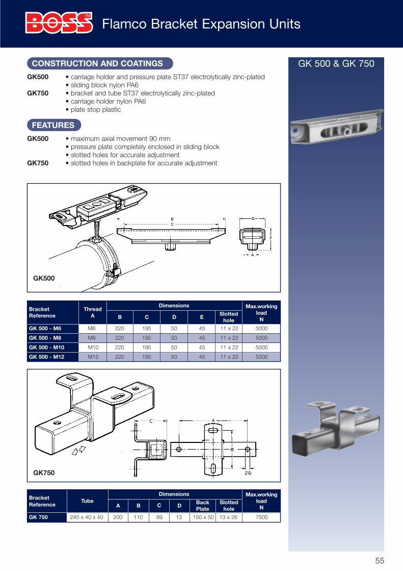
GK500 • carriage holder and pressure plate ST37 electrolytically zinc-plated• sliding block nylon PA6
GK750 • bracket and tube ST37 electrolytically zinc-plated• carriage holder nylon PA6• plate stop plastic
FEATURES
GK500 • maximum axial movement 90 mm• pressure plate completely enclosed in sliding block• slotted holes for accurate adjustment
GK750 • slotted holes in backplate for accurate adjustment
BracketReference
ThreadA B C D E
Slottedhole
Max.workingload
N
Dimensions
GK 500 - M6 M6 220 195 50 45 11 x 22 5000
GK 500 - M8 M8 220 195 50 45 11 x 22 5000
GK 500 - M10 M10 220 195 50 45 11 x 22 5000
GK 500 - M12 M12 220 195 50 45 11 x 22 5000
BracketReference
TubeA B C D
BackPlate
Slottedhole
Max.workingload
N
Dimensions
GK 750 245 x 40 x 40 200 110 89 13 150 x 50 13 x 26 7500
GK500
GK750
Flamco Bracket Expansion Units
GK 500 & GK 750
55
flamco 64pp 01/12/03 12:20 pm Page 55

Flamco DA Noise Suppression Fixtures
DA6 M6 dia. 40 x 30 dia. 8.5 32 55 – 500
DA8 M8 dia. 40 x 30 dia. 8.5 32 55 – 500
DA12 M12 dia. 50 x 40 M12 – 99 20 2000
CONSTRUCTION AND COATINGS
• housing electrolytically zinc-plated• suppressor unit: DA6 and DA8 – EPDM
DA12 natural rubber
FEATURES
• noise suppression 20 dB(A)• temperature-resistant from –40˚ to +110˚C• hardness: 65-70˚ Shore A
ReferenceB
AMax. working
load at20dB (A) NC D E F
Dimensions mm
DA6DA8
DA12
This typical installation shows howeasy it is to fit the DA fixture.
56
flamco 64pp 01/12/03 12:20 pm Page 56

Flamco SR Noise Suppression Strip
FOR INSERTION INTO HANGERS, CLIPS AND RAIL.
MATERIAL
• rubber SBR/EPDM
FEATURES
• at normal frequency and pressure range, noise suppression 20dB(A)• temperature-resistant from –40˚C to +110˚C• electrical values: specific resistance: 2 x 10⁹M ohm cm2
surface resistance: 2 x 10⁹M ohm NB. When noise-suppression strip is used the inside diameter of the associated clipmust be greater than the outside diameter of the pipe to be fitted.
SR0, 1, 2, 3: • breaking elongation 400%• tensile strength 500N/cm2
• impact resilience 35%SR4: • breaking elongation 350%
• tensile strength 400N/cm2
• impact resilience 35%
Reference Stripdimensions
mm
QualityShore hard-
ness
Specificgravity
gm/cm3Ref. B H D
Bracket Dimensions mm
SRO, 1, 2 and 3 SR 4
Hangerfitted withrubber strip
Rail fitted with SR4rubber strip
(BBA Approved)
57
SR0 BM8 10 x 1.2 LR155/1 55˚ 13.5 5.7 3 1.18
SR1 BK6 12 x 1.5 LR155/1 55˚ 16 7.2 3.9 1.29
BM10 12 x 1.5 LR155/1 55˚ 16 7.2 3.9 1.29
SR2 BK8 16 x 1.9 LR155/1 55˚ 20.5 10.5 6.3 1.29
BM12 16 x 1.9 LR155/1 55˚ 20.5 10.5 6.3 1.29
SR3 BK12 25 x 2.75 LR155/1 55˚ 31 12 6.3 1.29
SR4 Flamco – LR144/2 44˚ 30 16.5 7 1.32Rail
R1 to R6
flamco 64pp 01/12/03 12:18 pm Page 57

Flamco Rail R0, R1, R2, R3, R4 & R6.
Graphs A and B are based on the usual strengthcalculations and applying a maximum bendingstress of 140 N/mm2.In the blue-hatch area a deflection of 1/250 x L isexceeded and therefore not recommended.When there are two or more loads between sup-port points, graph A may be used only after theequivalent load is first determined using a correc-tion factor. A few examples are shown in Table 1providing that the “Number of Loads andDistribution” are as stated.
The equivalent load F, is determined as follows:
F1 = correction factor x F
Using the equivalent load F1, graph A may nowbe used for selecting the rail.
The end dimensions 1/4 and 1/8 must not bechosen larger.
RAIL SIZING AND CALCULATIONS
EXAMPLETwo 5in N.B. BS 1387 Heavy pipes have to be fitted to a rail and have acentre distance of 20cm between pipes. The distance between the respec-tive rails is 250cm.What type of Flamco rail should be used.
SOLUTIONThe weight of the pipe is (see table on page 59) 31.34kg/m, which means2.5m x 31.34 kg/m = 78.35 kg = 768.61N(1kg = 9.81N)
Table 1 shows how to determine the equivalent load, for 2 pipes spaced asshown the correlation factor
F1 = 1 x F should be usedF1 = 1 x 768.61M = 768.61N
TO DETERMINE THE SIZE OF FLAMCO RAILThe distance between the rail fixing points (L) is at most 40cm.(1/4, 1/2, 1/4 = 10cm + 20cm + 10cm = 40cm).
So that we see from Graph A that Flamco R2 can be used.
For further information regarding rail sizing please contact your local BSS (UK) branch.
Graph A
Graph B
F
F F1/4 1/2 1/4
F F1/6 1/3 1/61/3
FF F1/8 1/4 1/4F 1/4 1/8
F1
F1
F1
Number of loads &distribution
Equivalentload
Correctionfactor
F1=1xF
F1=1.67xF
F1=2xF
Specifications and Selection Information (R1, R2 & R4
BBA Approved)
58
flamco 64pp 01/12/03 12:18 pm Page 58

Flamco Pipe Weights and Bracket Spacings
The following tables can be used to determine the maximum load on each suspension point.Using the information and graphs you can select the size of rail required.
WEIGHTS OF STEEL AND COPPER TUBE
MAXIMUM SPANS FOR STEEL AND COPPER TUBE
Weight of BS 1387 Steel Tube filled with fresh water at 4˚C
Weight of BS 2871 Table ‘X’ filled with fresh water at 4˚C
Maximum Spans for BS 1387 Steel Tube (not lagged)
BS 1387 NB 1/2" 3/4" 1" 11/4" 11/2" 2" 21/2" 3" 4" 5" 6"
Medium Kg/m 1.44 1.96 3.05 4.19 5.03 7.40 10.34 13.76 21.08 29.97 38.77
Heavy Kg/m 1.64 2.24 3.51 4.80 5.75 8.31 11.55 15.22 23.09 31.34 40.50
O.D. 15 22 28 35 42 54 67 76 108 133 159
Kg/m 0.43 0.86 1.23 1.97 2.61 3.87 5.60 7.34 13.15 18.93 27.75
NOTES: 1. Above weights do not include insulation, valves, fittings, and forces due to thermalexpansion/contraction.2. All pipe supports should be calculated to comply with accepted or approved safetyregulations and be able to cope with atmosphere conditions.3. The loadings on each bracket must not exceed the maximum safe working loadrecommended.
Nominal Bore 1/2" 3/4" 1" 11/4" 11/2" 2" 21/2" 3" 4" 5" 6"
Metres 1.8 2.4 2.4 2.7 3.0 3.0 3.7 3.7 4.0 4.5 5.4
NOTES: 1. Where there are two or more sizes of pipes the common support spanshall be those required for the smallest bore pipework.
GAS: Supports for natural gas pipework shall comply with the requirements of BritishGas Publication IM/16.
Further details on design considerations can be found in BS 3974: Part 1 1974 orP.S.A. Standard Specification (M&E) No. 3.
Maximum Spans for BS2871 Table ‘X’ Copper Tube (not lagged)
Outside Dia. 15mm 22mm 28mm 35mm 42mm 54mm 67mm 76mm 108mm 133mm159mm
Metres 1.2 1.2 1.8 2.4 2.4 2.7 3.0 3.0 3.0 3.7 4.5
R0
R1
R2
R3
R4
R6
59
flamco 64pp 10/12/2003 5:34 pm Page 59

Flamco Installation Dimensions: BK Pipe Hangers
Calculating pipe distances from a ceiling The illustrations below show installations using R1 Rail or R2Rail. See Pages 30 and 31 for R4 Rail and R6 installations.
M6 70 A less 37 77+R A1 less R less 29 134+R A1 less R less 81 141+R A1 less R less 88
M8 107 A less 63 115+R A1 less R less 55 181+R A1 less R less 116 178+R A1 less R less 113
M12 120 A less 66 132+R A1 less R less 57 229+R A1 less R less 40 – –
Hanger ‘B’Reference mmBK 12 x 105 30BK 12 x 108 30BK 12 x 113 32BK 12 x 114 29BK 12 x 121 27BK 12 x 125 34BK 12 x 127 28BK 12 x 133 33BK 12 x 137 36BK 12 x 140 34BK 12 x 144 38BK 12 x 146 41BK 12 x 152 38BK 12 x 159 40BK 12 x 165 42BK 12 x 168 40BK 12 x 171 44BK 12 x 178 44BK 12 x 185 46BK 12 x 193 48BK 12 x 199 48BK 12 x 205 50BK 12 x 216 51BK 12 x 219 52BK 12 x 225 50BK 12 x 231 52BK 12 x 241 56BK 12 x 251 52BK 12 x 267 50BK 12 x 273 55BK 12 x 299 60BK 12 x 323 67
This ‘B’ dimension is also required
when using the BK 12 range of hangers
Dimension ‘R’ will
depend on the type
of rail chosen
Centre distance of
the pipe to the ceiling
Installation dimensions when
using BO extension pieces.
BK6 BK6 120 H-60
BK8 BK8 155 H-80
BK8 BK6 110 H-55
BK12 BK12 230 H-115
BK12 BK8 180 H-115
BK12 BK6 140 H-80
H = min. distance in the particularassembly.The length of the threaded roddepends on the distance H, and isthus reduced by the dimension shownin the table.
ThreadedRod
Min. Ain mm
Length Din mm
Length Din mm
Min. A1 inmm
Length Din mm
Min. A1 inmm
Length Din mm
Min. A1 inmm
Pipe hang-erA
Pipe hang-erB
Min. Hmm
Length Dmm
Dim.max
R1 R2 R3 R4 R5
R 15 20 40 46 56
BK6 A + 1/2 clip inside dia.
BK8 A + 1/2 clip inside dia.
BK12 A + 1/2 clip inside dia.+B
60
flamco 64pp 01/12/03 12:18 pm Page 60

Flamco Installation Dimensions: BSA Clipsers
The illustrations below show installations using R1 Rail or R2 Rail.See page 30 and 31 for R4 Rail and R6 Rail installations.
BSA 14/16 up to BSA 25/28 23+R A1 less R 86+R A1 less R less 56 89+R A1 less R less 59
BSA 33/37 up to BSA 89/91 25+R A1 less R 88+R A1 less R less 58 91+R A1 less R less 61
BSA 108/116 up to BSA 165/168 30+R A1 less R " “ 93+R A1 less R less 61
BSA 14/16 up to BSA 25/28 14 A less 6
BSA 33/37 up to BSA 89/91 16 A less 8
BSA 108/116 up to BSA 165/168 20 A less 10
BSA 14/16 up to BSA 25/28 A +1/2 clip inside dia.
BSA 33/37 up to BSA 89/91 A +1/2 clip inside dia.
BSA 108/116 up to BSA 165/168 A +1/2 clip inside dia.
Calculating pipe distances from a
ceiling when using Flamco rail.
ClipReference
Min. ALength
Dmm
Min.
A1
mm
LengthD
mm
Min. A1
mm
LengthD
mm
Pipe distances from a ceiling or wall.
ClipReference
ClipReference Distance calculation
Min. Amm
Length Dmm
Centre distance of the pipe to the ceiling.
Dimension ‘R’ will depend on the type of rail chosen
Dimensionsmm
R1 R2 R3 R4 R5
R 15 20 40 46 56
61
flamco 64pp 01/12/03 12:18 pm Page 61

Flamco T-Plus Branch Connection
The fastest and simpliest method of making a T-piece CouplingThe traditional methods of teeing into a supply line meant shutting down the system, drainingdown then re-priming and venting when the job was complete - operations that could interruptproduction and invariably involve a considerable number of man hours.The introduction of the Flamco T-plus eliminates the time consuming operations normally associ-ated with installing branch connections and enables the complete pipework to be fabricated andcommissioned without shut-down. The units can be supplied for use on steel pipe - includingheavy quality tube to BS 1387 - and copper pipe to BS 2871.
1. Position the two parts of the Flamco T-plus on to the supply pipe. Insert thefour screws and in diagonal sequencetighten the screws until the T-plus is fullysecured
3. When the branch system is completelypiped-up, remove the pin cover on the T-plus and strike the pin a clean, sharp,square blow with a hammer. This will openthe supply to the branch pipework
2. Connect up the branch systempipework
* It is essential that the branch outlet does not contain any liquid prior to striking the firing pin. Isolated valves should be fitted if necessary.
Steel Pipe ApplicationsPressure rating: Up to 25 bar (360 lbf/in2)Temperature rating: Up to 120°C (250°F)Body and Fastening Clamp material:Malleable Cast IronPiston, Cover and Screws: Steel
Copper Pipe Applications(W.R.C.) ApprovedPressure rating: Up to 16 bar (230 lbf/in2)Temperature rating: Up to 90°C (194°F)Body material: Non-dezincifiable BrassFastening Clamp and Cover Material:Brass
Pipe Size Branch Size* Branch Thread Type Product Code
1/2in 1/2in 1/2in fem BSP 10 190400023/4in 1/2in 1/2in fem BSP 10 19040013
1in 3/4in 3/4in fem BSP 10 19040205
11/4in 1in 1in fem BSP 10 19040408
11/2in 11/4in 11/4in fem BSP 10 19040504
2in 11/4in 11/4in fem BSP 10 19040515
21/2in 11/4in 11/4in fem BSP 10 19040526
3in 11/4in 11/4in fem BSP 10 19040548* Orifice size in supply pipe is not identical to nominal bore of branch pipe
PRESSURE DROPThe following graphs indicate the pressure drop for the various branch sizes based on water at 20°C (68°F)
Steel Pipe Units Copper Pipe Units
Principle of OperationA piston, which locates at rightangles to the supply pipe whenthe T-plus is fitted in position, isvertically bored to the nominaldiameter of the branch size. Thefront face of the piston is dished toact as a chip-stream and also toprovide a cutting edge. An ‘O’ ringand star washer arrangement isfitted adjacent to the rear face.In operation, when the firing pin isstruck, the charge sets up a gaspressure which drives the pistonforward. The cutting edge shearsthe pipe and the dished face car-ries the pipe swarf clear of thehole and contains it against thebody wall. When the piston hasreached its full travel, the verticalbore aligns with the hole cut in thepipe to allow free flow from thesupply line to the branchpipework. The star washerarrangement engages a slot in thepiston cylinder to lock the piston inthe open position. (On earliermodels a circlip was fitted in placeof the star washer.)
NOTE:The Flamco T-Plus branch con-nections must not be used onpipelines carrying fuel or otherinflammable media, or activat-ed in fire hazard areas.Flamco T-plus are not suitablefor use on sprinkler systems.
Cylinder"O" Ring
PistonStarWasher
FiringPin
MainSupply
DishedFace
BranchLine
48
62
Pipe Size Branch Size* Branch Thread Type Product Code
15mm 1/2in 1/2in male BSP 01 19041303
22mm 1/2in 1/2in male BSP 01 19041314
28mm 3/4in 3/4in male BSP 01 19041506
35mm 3/4in 3/4in female BSP 01 19041517* Orifice size in supply pipe is not identical to nominal bore of branch pipe
flamco 64pp 01/12/03 12:18 pm Page 62

Flamco International Approvals
63
63025 Flamco Cover 2007 3/7/07 16:30 Page 3

BSS BRANCH LOCATIONS THROUGHOUT THE UK & IRELAND
Pipeline & Heating Solutions
ABERDEEN Unit 5, South Middleton Base, Greenwell Road,
East Tullos, Aberdeen AB12 3AX
Tel: 01224 292929 Fax: 01224 898252
Email: [email protected]
BELFAST 36-38 Duncrue Road, Duncrue Industrial Estate,
Belfast, Northern Ireland BT3 9BP
Tel: 028 9078 4000 Fax: 028 9078 4010
Email: [email protected]
BIRMINGHAM Units 2 & 4 Crystal Drive, Sandwell Business Park,
Smethwick, Warley, West Midlands B66 1QG
Tel: 0121 552 6000 Fax: 0121 552 5363
Email: [email protected]
BIRMINGHAM CENTRAL Unit 49, Gravelly Industrial Park,
Tyburn Road, Erdington, Birmingham B24 8TG
Tel: 0121 322 0370 Fax: 0121 322 2296
Email: [email protected]
BOREHAMWOOD Chester Road, Borehamwood, Herts WD6 1LT
Tel: 020 8327 4100 Fax: 020 8327 4101
Email: [email protected]
BOURNEMOUTH Unit 3B, Broom Road Business Park,
Broom Road, Poole, Dorset BH12 4PA
Tel: 01202 711300 Fax: 01202 711301
Email: [email protected]
BRENTFORD Transport Avenue, Great West Road,
Brentford, Middlesex TW8 9HF
Tel: 020 8232 2727 Fax: 020 8232 2730
Email: [email protected]
BRISTOL Albert Road, St Philips, Bristol BS2 0BS
Tel: 0117 972 7900 Fax: 0117 972 7901
Email: [email protected]
CAMBRIDGE Unit 3, Rosemary Lane, Cambridge CB1 3LQ
Tel: 01223 404040 Fax: 01223 240420
Email: [email protected]
CARDIFF Unit 4, Trident Park, Glass Avenue, Ocean Way,
Cardiff CF24 5EN
Tel: 029 2043 2400 Fax: 029 2049 7815
Email: [email protected]
CARLISLE Unit 2A, Port Road Business Park, Carlisle CA2 7AJ
Tel: 01228 517600 Fax: 01228 598090
Email: [email protected]
CHESSINGTON Oakcroft Road, Hook Rise Industrial Estate,
Chessington, Surrey KT9 1RH
Tel: 020 8974 3800 Fax: 020 8391 5241
Email: [email protected]
COLCHESTER Unit 6, Smeaton Close, Severalls Industrial Park
Colchester, Essex CO4 9QY
Tel: 01206 754720 Fax: 01206 752649
Email: [email protected]
CORK Unit 20, South Link Park, Ballycurren Road, Grange, Cork
Tel: 00353 21 321588 Fax: 00353 21 321595
Email: [email protected]
COVENTRY Unit 17, Torrington Avenue, Coventry,
West Midlands CV4 9HN
Tel: 024 7669 4744 Fax: 024 7647 0574
Email: [email protected]
CRAWLEY 12A Denvale Trade Park, Haslett Avenue East,
Crawley RH10 1SS
Tel: 01293 610170 Fax: 01293 523388
Email: [email protected]
CROYDON Unit 34, Factory Lane, Croydon, Surrey CR0 3RL
Tel: 020 8662 2300 Fax: 020 8681 6142
Email: [email protected]
DARTFORD Unit 11 Orbital One, Green Street, Green Road,
Dartford, Kent DA1 1QG
Tel: 01322 289039 Fax: 01322 289149
Email: [email protected]
DERBY Riverside Road, Pride Park, Derby DE24 8HH
Tel: 01332 685600 Fax: 01332 685601
Email: [email protected]
DUBLIN White Heather Industrial Estate,
301 South Circular Road, Dublin 8
Tel: 00353 14 165100 Fax: 00353 14 165165
Email: [email protected]
DUNDEE Unit 1-3, Rutherford Road,
Dryburgh Industrial Estate, Dundee DD3 8HE
Tel: 01382 823700 Fax: 01382 826921
Email: [email protected]
EDINBURGH Unit 2A, Pentland Industrial Estate, Loanhead,
Midlothian, Edinburgh EH20 9QH
Tel: 0131 440 5900 Fax: 0131 440 3761
Email: [email protected]
EXETER Unit 6, Otter Court, Manaton Close,
Matford Business Park, Exeter EX2 8PF
Tel: 01392 457500 Fax: 01392 425976
Email: [email protected]
GLASGOW Unit A, Vermont Street, Kinning Park, Glasgow G41 1LU
Tel: 0141 418 4444 Fax: 0141 429 2638
Email: [email protected]
GLOUCESTER Eastbrook Road Trading Estate, Gloucester, GL4 3DB
Tel: 01452 872200 Fax: 01452 309899
Email: [email protected]
GRIMSBY Appian Way, Europa Park, Grimsby DN31 2FD
Tel: 01472 265100 Fax: 01472 241638
Email: [email protected]
HULL Copenhagen Road, Sutton Fields Industrial Estate,
Hull, East Yorkshire HU7 0YH
Tel: 01482 625800 Fax: 01482 838870
Email: [email protected]
KINGS CROSS Unit 2, 1 Brewery Road, Islington, London N7 9QJ
Tel: 020 7619 7600 Fax: 020 7700 2482
Email: [email protected]
LEEDS Turnkey Park Estate, Whitehall Road, Leeds LS12 6AD
Tel: 0113 203 2203 Fax: 0113 279 8662
Email: [email protected]
LEICESTER 66 Cobden Street, Leicester LE1 2LB
Tel: 0116 242 7800 Fax: 0116 253 2456
Email: [email protected]
LEWES Unit 5, South Downs Business Park, Brooks Road,
Lewes, East Sussex BN7 2FB
Tel: 01273 485000 Fax: 01273 480709
Email: [email protected]
LINCOLN Units 3/4, Crofton Drive, Allenby Industrial Estate,
Lincoln LN3 4NR
Tel: 01522 565700 Fax: 01522 512678
Email: [email protected]
LIVERPOOL 82/94 Great Howard Street, Liverpool L3 7AX
Tel: 0151 482 2500 Fax: 0151 207 2317
Email: [email protected]
LONDON DOCKLANDS Units 6 & 7, Thomas Road Industrial Estate,
Limehouse, London E14 7BN
Tel: 020 7531 3900 Fax: 020 7537 4849
Email: [email protected]
LUTON 1 Trojan Court, Laporte Way, Luton, Beds LU4 8RJ
Tel: 01582 875600 Fax: 01582 452050
Email: [email protected]
MAIDSTONE Unit 5, Wood Close, Quarry Wood Industrial Estate,
Aylesford, Kent ME20 7UB
Tel: 01622 713600 Fax: 01622 713616
Email: [email protected]
MANCHESTER Unit 1, Columbus Way, Off Broadway, Salford,
Manchester M50 1UU
Tel: 0161 888 6464 Fax: 0161 888 6465
Email: [email protected]
NEWCASTLE Sanderson Street, Newcastle-upon-Tyne NE4 7PJ
Tel: 0191 256 5100 Fax: 0191 272 3115
Email: [email protected]
NORTHAMPTON Riverside Way, Bedford Road,
Northampton NN1 5NX
Tel: 01604 251400 Fax: 01604 620588
Email: [email protected]
NORWICH Unit 13, Alston Road, Hellesdon Park Industrial Estate,
Norwich, Norfolk NR6 5DS
Tel: 01603 253200 Fax: 01603 418839
Email: [email protected]
NOTTINGHAM Unit 3, Longwall Avenue,
Queens Drive Industrial Estate, Nottingham NG2 1NA
Tel: 0115 943 5900 Fax: 0115 986 1099
Email: [email protected]
OXFORD Unit C Taurus, Peterley Road, Horspath Industrial Estate,
Cowley, Oxford OX4 2TZ
Tel: 01865 398870 Fax: 01865 777552
Email: [email protected]
PETERBOROUGH Unit 2a, Centurion Business Centre,
Sturrock Way, Bretton, Peterborough PE3 8YB
Tel: 01733 336000 Fax: 01733 265790
Email: [email protected]
PLYMOUTH Block G, St. Modwyn Road, Parkway Industrial Estate,
Plymouth, Devon PL6 8LH
Tel: 01752 675300 Fax: 01752 220063
Email: [email protected]
PRESTON Unit 1 & 2, Brookfield Street, Preston PR1 1NR
Tel: 01772 557800 Fax: 01772 259285
Email: [email protected]
READING Units A2 & A3, Worton Drive,
Worton Grange Industrial Estate, Reading, Berks RG2 0TG
Tel :0118 923 8900 Fax: 0118 975 0497
Email: [email protected]
ROMFORD King George Close, Eastern Avenue West,
Romford, Essex RM7 7PS
Tel: 01708 771800 Fax: 01708 723168
Email: [email protected]
SHEFFIELD Unit 15, Oakham Drive, Parkwood Industrial Estate,
Sheffield S3 9QX
Tel: 0114 289 3900 Fax: 0114 276 7178
Email: [email protected]
SOUTHAMPTON Unit A1, Parham Drive,
Boyatt Wood Trading Estate, Eastleigh, Hampshire SO50 4NU
Tel: 023 8068 3700 Fax: 023 8064 3928
Email: [email protected]
STOCKTON North Tees Industrial Estate, Portrack Lane,
Stockton on Tees TS18 2RL
Tel: 01642 665500 Fax: 01642 674652
Email: [email protected]
STOKE ON TRENT Units 6 & 7, Etruria Way, Basford,
Stoke on Trent ST4 6JQ
Tel: 01782 382382 Fax: 01782 621456
Email: [email protected]
SWANSEA Century Park, Valley Way, Swansea Enterprise Park,
Swansea SA6 8QP
Tel: 01792 762300 Fax: 01792 775922
Email: [email protected]
SWINDON Unit 4A, Euroway Industrial Estate, Ramsden Road,
Swindon SN5 8YW
Tel: 01793 601500 Fax: 01793 512144
Email: [email protected]
WANDSWORTH Unit 5, 307-309 Merton Road, Wandsworth,
London, SW18 5JS
Tel: 020 8877 9191 Fax: 020 8877 9719
Email: [email protected]
WIGAN Unit 2, Lockflight Buildings, Wheatlea Industrial Estate,
Wheatlea Road, Wigan WN3 6XP
Tel: 01942 405540 Fax: 01942 405541
Email: [email protected]
WIRRAL Rossmore Road East, Rossmore Industrial Estate,
Ellesmere Port, South Wirral, Cheshire CH65 3DD
Tel: 0151 348 5400 Fax: 0151 357 2001
Email: [email protected]
Registered Office: The BSS Group PLC, Fleet House, Lee Circle, Leicester LE1 3QQ, England.
Tel: 0116 262 3232 Fax: 0116 253 1343 E-mail: [email protected] Web: www.bssuk.co.uk
BOSSFLAMCO/0707/3
63025 Flamco Cover 2007 3/7/07 16:30 Page 4