![Ouray 400 Sistema [U4] Selux · U4-#2. U4-#3. U4-#4 U4-Fixture # Series Optics. Mounting Light. Options. Engine. Rivnut. Pairs RN Fixture # CCT Finish. Voltage *Refer to chart on](https://static.fdocuments.net/doc/165x107/5f94b53bcc58146dfa1c1ffc/ouray-400-sistema-u4-selux-u4-2-u4-3-u4-4-u4-fixture-series-optics-mounting.jpg)
FIXTURE MOUNTING - Howard Lighting...
3
DTDC-LED Dusk-to-Dawn Warning Please read instructions carefully before attempting to install fixture and retain instructions for future reference. Caution: To avoid electrical shock hazard. • Turn off the electricity before installing or servicing this fixture. • Electrical connections need to comply with National Electric Code and Local Electric Code. • The fixture should be installed by a qualified electrician. General Safety Information WARNING: 1. Before making any wiring connections, make sure power is disconnected. 2. Do not touch the yellow portion of the LED when removing the acrylic refractor. Damage may occur. INSTALLATION INSTRUCTIONS FIXTURE MOUNTING Note: Assure that fixture is mounted to a structurally sound surface that will support the fixture. 1. Select a location on a structurally secure wall or pole, minimum 4 feet from the ground. 2. Place mounting section of fixture onto desired mounting surface, mark and drill holes for mounting. 3. This fixture can be mounted with three lag screws which are provided. See Figure 1, 26. 4. Install the two bottom lag screws first. 5. Place the fixture on the two bottom lag screws and install the top lag screw. 6. Tighten the top lag screw first and then tighten the remaining lag screws. FIXTURE WIRING Note: Connect fixture to supply wires, make sure power is off. 1. Feed supply wires through arm and make wiring connections in the fixture. 2. Connect the black fixture wire to the black house power supply wire and the white fixture wire to the white house supply wire first. 3. The fixture must be grounded. Attach ground lead to green ground screw. See Figure 1, 23. 4. Secure the cover plate with two screws, two nuts and washers. See Figure 1. 20,21,25. For models: DTDC-30-LED-120 DTDC-30-LED-120-A (with arm; see pg. 3)
Transcript of FIXTURE MOUNTING - Howard Lighting...
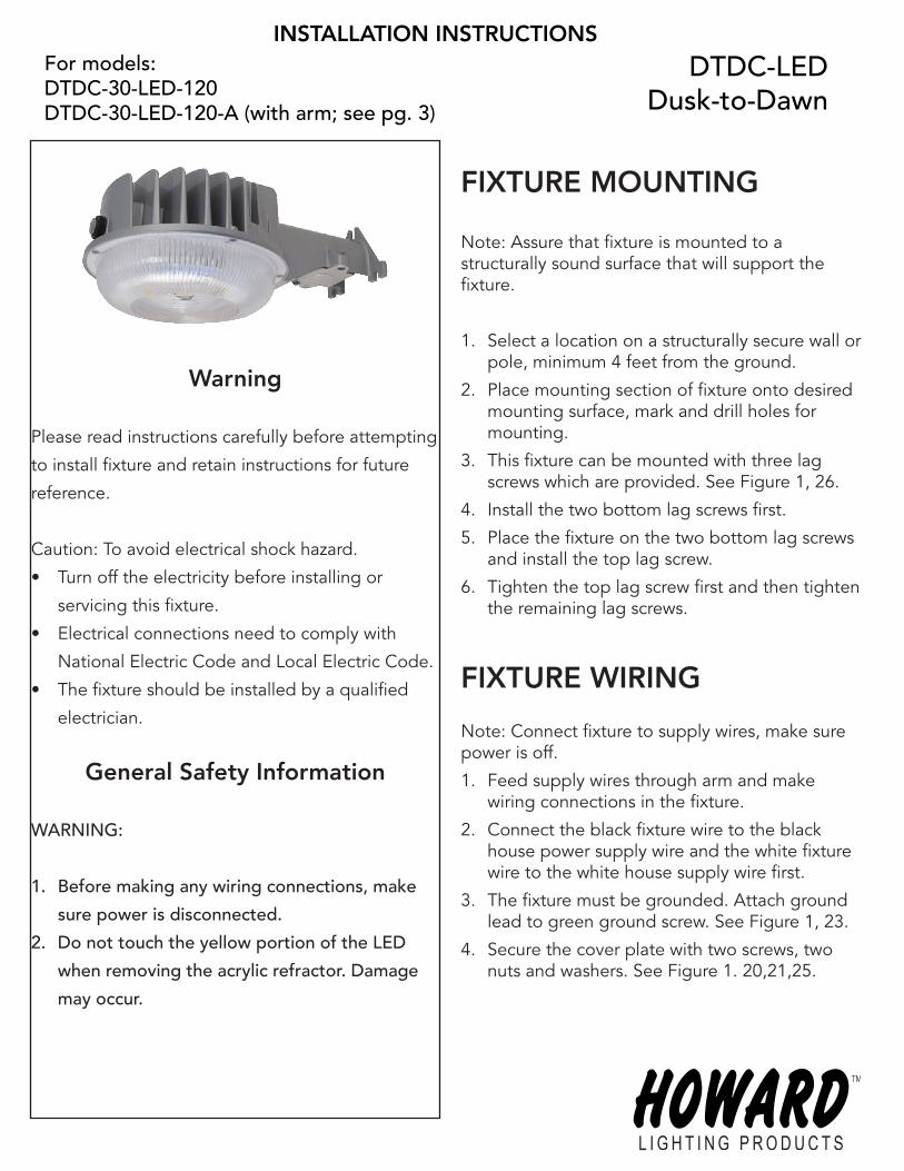
DTDC-LEDDusk-to-Dawn
Warning
Please read instructions carefully before attempting
to install fixture and retain instructions for future
reference.
Caution: To avoid electrical shock hazard.
• Turn off the electricity before installing or
servicing this fixture.
• Electrical connections need to comply with
National Electric Code and Local Electric Code.
• The fixture should be installed by a qualified
electrician.
General Safety Information
WARNING:
1. Before making any wiring connections, make
sure power is disconnected.
2. Do not touch the yellow portion of the LED
when removing the acrylic refractor. Damage
may occur.
INSTALLATION INSTRUCTIONS
FIXTURE MOUNTING
Note: Assure that fixture is mounted to a structurally sound surface that will support the fixture.
1. Select a location on a structurally secure wall or pole, minimum 4 feet from the ground.
2. Place mounting section of fixture onto desired mounting surface, mark and drill holes for mounting.
3. This fixture can be mounted with three lag screws which are provided. See Figure 1, 26.
4. Install the two bottom lag screws first.
5. Place the fixture on the two bottom lag screws and install the top lag screw.
6. Tighten the top lag screw first and then tighten the remaining lag screws.
FIXTURE WIRING
Note: Connect fixture to supply wires, make sure power is off.
1. Feed supply wires through arm and make wiring connections in the fixture.
2. Connect the black fixture wire to the black house power supply wire and the white fixture wire to the white house supply wire first.
3. The fixture must be grounded. Attach ground lead to green ground screw. See Figure 1, 23.
4. Secure the cover plate with two screws, two nuts and washers. See Figure 1. 20,21,25.
For models:DTDC-30-LED-120DTDC-30-LED-120-A (with arm; see pg. 3)
Input voltage: 120v 50/60HzLumen Output: 1800 lmColor Temperature: 4100KPhotocell: 120v
Technical Specifications
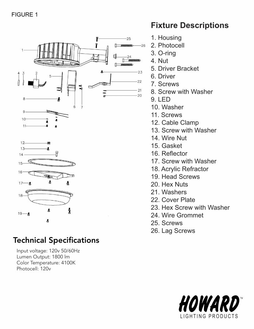
FIGURE 1
1. Housing2. Photocell3. O-ring4. Nut5. Driver Bracket6. Driver7. Screws8. Screw with Washer9. LED10. Washer11. Screws12. Cable Clamp13. Screw with Washer14. Wire Nut15. Gasket16. Reflector17. Screw with Washer18. Acrylic Refractor19. Head Screws20. Hex Nuts21. Washers22. Cover Plate23. Hex Screw with Washer24. Wire Grommet25. Screws26. Lag Screws
Fixture Descriptions
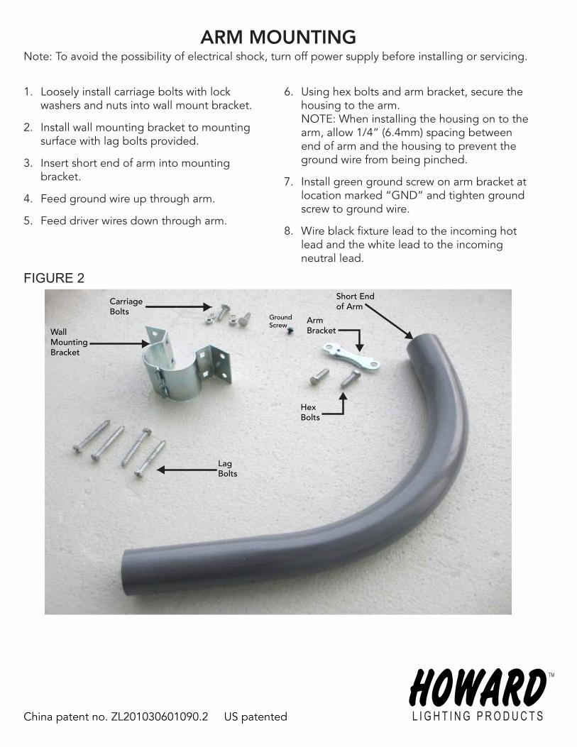
Note: To avoid the possibility of electrical shock, turn off power supply before installing or servicing.ARM MOUNTING
1. Loosely install carriage bolts with lock washers and nuts into wall mount bracket.
2. Install wall mounting bracket to mounting surface with lag bolts provided.
3. Insert short end of arm into mounting bracket.
4. Feed ground wire up through arm.
5. Feed driver wires down through arm.
6. Using hex bolts and arm bracket, secure the housing to the arm. NOTE: When installing the housing on to the arm, allow 1/4” (6.4mm) spacing between end of arm and the housing to prevent the ground wire from being pinched.
7. Install green ground screw on arm bracket at location marked “GND” and tighten ground screw to ground wire.
8. Wire black fixture lead to the incoming hot lead and the white lead to the incoming neutral lead.
FIGURE 2
Carriage Bolts
WallMountingBracket
Lag Bolts
Short Endof Arm
Arm Bracket
GroundScrew
Hex Bolts
China patent no. ZL201030601090.2 US patented