Fixing generalization defects in uml use case...
13
Transcript of Fixing generalization defects in uml use case...

Fixing generalization defects
in uml use case diagrams
Xavier Dolques, Marianne Huchard, Clémentine Nebut, and Philippe Reitz
LIRMM, CNRS and Université Montpellier II, Montpellier{dolques,huchard,nebut,reitz}@lirmm.fr
Abstract. Use case diagrams appear in early steps of a UML-based de-velopment. They capture user requirements, structured by the conceptsof use cases and actors. An admitted good modeling practice is to de-sign simple, easy-to-read use case diagrams. That can be achieved byintroducing relevant generalizations of actors and use cases. The paperproposes an approach based on Formal Concept Analysis and one of itsvariants, Relational Concept Analysis, to refactor a use case diagram asa whole in order to make it clearer. We developed a tool and studied theresults on about twenty examples, concluding on the relevancy of theapproach on our benchmark.
Keywords: Formal Concept Analysis, uml use case diagrams
1 Introduction
Within a UML-based development, the very �rst model to be designed is theuse case diagram, that is later used all over the modeling process. For example,in the Rational Uni�ed Process [11], the development process is driven by theuse cases: the use cases are continuously used to inject further functionalities instatic models, they guide the testing plan, etc. Thus even if the use case diagramis probably the furthest one from implementation, it takes a large place in thedesign of many artifacts. Use case diagrams model the boundary of a system, theactors that interact with the system, and the use cases (main functionalities of-fered to actors by the system). Use cases are linked to the actors interacting withthem, and use cases may be organized using three types of relation: inclusion,extension (that can be seen as conditional inclusion), and generalization.
As mentioned in the UML user guide [2], �Organizing your use cases by ex-tracting common behavior (through include relationships) and distinguishingvariants (through extend relationships) is an important part of creating a sim-ple, balanced, and understandable set of use cases for your system.� A goodpractice for use case diagrams is to make them simple to read [1], so as to catchat �rst glance the boundaries of the system, its main actors and main func-tionalities. Thus a tangled use case diagram (e.g. with numerous and tangledrelations linking use cases to actors and to other use cases) will regularly brakethe development since a designer, each time he or she will consult it, will have adelay to understand (again) the use case diagram.

2 Dolques et al.
In this paper, we investigate an approach to make use case diagrams clearerby introducing generalized actors and use cases to factorize relations. Our ap-proach is based on several refactoring patterns (e.g. when two use cases includethe same third one, they can be generalized by a new use case including this thirduse case), that are globally combined using Formal Concept Analysis (FCA)and one of its variant Relational Concept Analysis (RCA). The approach is im-plemented in an Eclipse-integrated tool that takes as input a UML diagram,encodes it into FCA (or RCA) contexts, generates the corresponding conceptlattices, and �nally produces as output the refactored use case diagram. Westudied the results of this approach on several examples, comparing the pairs ofinput diagram/output diagram, and FCA versus RCA.
The following of the paper is structured as follows. We �rst illustrate inSection 2 the use case diagram refactoring with an example that will later beused to illustrate our approach. Section 3 details the used refactoring patterns,and Section 4 explains how they are globally applied using FCA or RCA. Resultsof our experiments on examples are given in Section 5. Section 6 compares ourapproach w.r.t. related work.
2 A motivating example
This section presents a motivating example. We brie�y recall the main elementsinvolved in UML use case diagrams, and then illustrate the use case generaliza-tion defects. The application we are interested in should allow various users tobuy products or apply for interships. Figure 1 shows a use case diagram for thisapplication. Actors represent the role(s) played by external persons or systems
Fig. 1. A use case diagram for the internship example
that interact with the modelled system. They are depicted using a �stick man�icon (or a box stereotyped <<actor>> with the name of the actor). In the ex-ample, three roles are identi�ed: a company, a registered client, and a registered

Fixing generalization defects in uml use case diagrams 3
company. Use cases model large functionalities. They are depicted by a named el-lipse. In our example, we �nd for example the use case Apply for Multi-Period
Internship, modelling the functionality corresponding to the possibility to ap-ply for internships organized over several periods (for example a day per month).Use cases are associated (graphically by a continuous line) to the actors involvedin them: actors to which the functionality is dedicated or secondary actors thatinteract with the system during the achievement of the functionality. In ourexample, the use case Apply for Multi-Period Internship is linked to theRegistered Client and the Registered Company actors, since both of thoseactors can apply for such internships (whereas non-registered companies can-not). A use case may include another one. Graphically, it is shown by a dashedoriented arrow stereotyped by <<include>>. Semantically, that means that theincluding use case explicitly incorporates the behaviour of the included use case.For example, the use case Buy with Bank Transfer includes the use case SendRecapitulative Email. A use case may be extended by another one. Graph-ically, it is shown by a dashed oriented arrow stereotyped by <<extend>>.Semantically, that means that the extended use case may include the behaviourof the extending use case. In our example, a recapitulative email may be sentwhile realizing an appliance for a multi-period internship. Conditions for theextension and extension points can complete the extension relationship, as dis-cussed later in the paper. UML provides two generalization mechanisms in usecase diagrams: for actors and for use cases. Figure 2 shows a refactored use casediagram for the internship example, in which those two mechanisms appear. A
Fig. 2. A refactored use case diagram for the internship application using FCA
use case may generalize another one: the child use case inherits the behaviour ofthe parent use case, as well as its meaning. It is graphically represented by anedge ended by a triangle, like for class inheritance. In the refactored example ofFigure 2, the use case Buy generalizes the use cases Buy with Bank Transfer

4 Dolques et al.
and Buy with Fidelity Card. An actor may generalize another one: the childactor inherits the roles of the parent actor, i.e. its interactions with use cases.For example in Figure 2, the actor RegisteredCompany specializes the actorCompany.
The initial use case diagram of Figure 1 su�ers from the large number ofcrossed links from actors to use cases, and to a lesser extent, from the large num-ber of links from use cases to use cases. For example, the actor RegisteredCompa-ny is linked to four use cases. Introducing a generalization from this actor to theactors Company and RegisteredClient is semantically correct and factorizesthose four links: in the refactored use case diagram proposed in Figure 2, the ac-tor RegisteredCompany inherits its links to the use cases from its two parent ac-tors. Similarly, the two inclusions of the use case Client Identification (resp.Send Recapitulative Email) by the use cases Buy with Fidelity Card andBuy with Bank Transfer can be factorized introducing the sound use case Buy.Last, the two extensions can be factorized introducing the sound Apply For
Internship use case.The approach we propose aims at detecting the possible relevant generaliza-
tions in a use case diagram, and introduces them in order to obtain a simpler usecase diagram. For that, we �rst identify (in refactoring patterns) situations forwhich introducing a generalization may be useful. Then to automatically applythese patterns, we use Formal Concept Analysis (FCA) or one of its variantsRelational Concept Analysis (RCA). The refactoring patterns are presented inthe next section while the FCA/RCA application is detailed in Section 4.
3 Local refactoring patterns
To correct generalization defaults, we propose a systematic approach that in-troduces more general elements (actors or use cases) based on the detection ofshared relations. However, this does not guarantee the relevance of factorizingthe relations using more general use cases or actors. The pertinence of refactor-ings is particularly challenged by the lack of information e.g. no role mention isgiven. In this section, we study several refactoring proposals. We consider herea simple set-based semantics, associating to a use case diagram the set of itsactors and for each actor the feasible sequences of leaf use cases. The use caseshaving specializations are supposed to be abstract, i.e. replaced by one of theirspecializations during a concrete usage of the system.
Refactorings between use cases. Table 1 presents the refactoring patterns foruse cases. The pattern I considers the situation of two use cases A and B includingthe same use case C. In this situation, all the sequences that can be performedby an actor and that contain A (resp. B) will also contain C. We propose to refac-tor the two inclusions as seen in the refactored pattern: a sequence that can beperformed by an actor and containing A will still contain C, since A specializes Nthat contains C. In situation II, when the two conditions of extension CA and CB
are identical and that the extension points (that roughly specify when the ex-tension should occur) are also identical, then a generalization can be introduced.

Fixing generalization defects in uml use case diagrams 5
It frequently occurs that extension points and conditions are not speci�ed forthe extensions, in this case we propose to apply the refactoring, whereas if theextension conditions or the extension points are di�erent, this refactoring doesnot apply. The situation III introduces a specialization refactoring. The sourcepattern owns a use case A for which the sets of outgoing include relations andincoming extend relations are strictly included in those of another use case B.The proposed refactoring derives B from A and removes from B the inheritedrelations. Situations to factorize incoming include relations or outgoing extendrelations were studied but rejected since they were not pertinent.
Table 1. Refactoring patterns between use cases
source pattern refactored pattern
I
A
B
C
«include»
«include»
N
A B
C
«include»
outgoing include
II
A
EA
B
EB
C
Condition : CAExtensionPoint : EA
Condition : CBExtension Point : EB
«extend»
«extend»
N
Ext
A B
C
Condition : CondExtension Point : Ext
«extend»
incoming extend
IIIshared extend and include
Refactorings between actors. Table 2 presents two refactoring patterns be-tween use cases and actors. The �rst one (I) introduces a specialization relationbetween actors when the set of associations of one actor is strictly included inthe associations of another actor, and then removes the inherited associations.

6 Dolques et al.
The second one (II) adds an abstract actor when the sets of associations of twoactors have a non-empty intersection but each actor has associations that theother one does not have.
Table 2. Refactoring patterns between actors and use cases
source pattern refactored pattern
I
Actor1
Actor2
A
B
Actor1
Actor2
A
B
Actors and use cases with specialization
II
Actor1
Actor2
A
B
CActor1
Actor2
Actor3
B
A
C
Actors and use cases with factoring
4 Global refactoring through Formal Concept Analysis
The refactoring schemas presented in the previous section do not give a uniquesolution to deal with a use case diagram as a whole. For that, we use FormalConcept Analysis [7] which systematically groups objects owning common char-acteristics in a minimal generalization structure.
Refactoring with FCA. We build two formal contexts (Table 3). In one con-text, we associate an actor with a use case when the actor is involved in theuse case. In the second context, use cases are described by inclusion of anotheruse case, extension by another use case and names. Figures 3 and 4 present thelattices. In the lattice of actors (Fig. 3), a generalization relationship is intro-duced: C2, which represents RegisteredCompany, is indeed a subconcept of C1(RegisteredClient) and C3 (Company). This is an application of the �rst actor-use case refactoring. The lattice of use cases (Fig. 4) highlights two refactorings.The outgoing-include refactoring appears on the left: C5 generalizes the conceptsthat introduce Buy with Fidelity Card (C8) and Buy with Bank Transfer
(C11) because these two use cases include Send Recapitulative Email and
Fixing generalization defects in uml use case diagrams 7
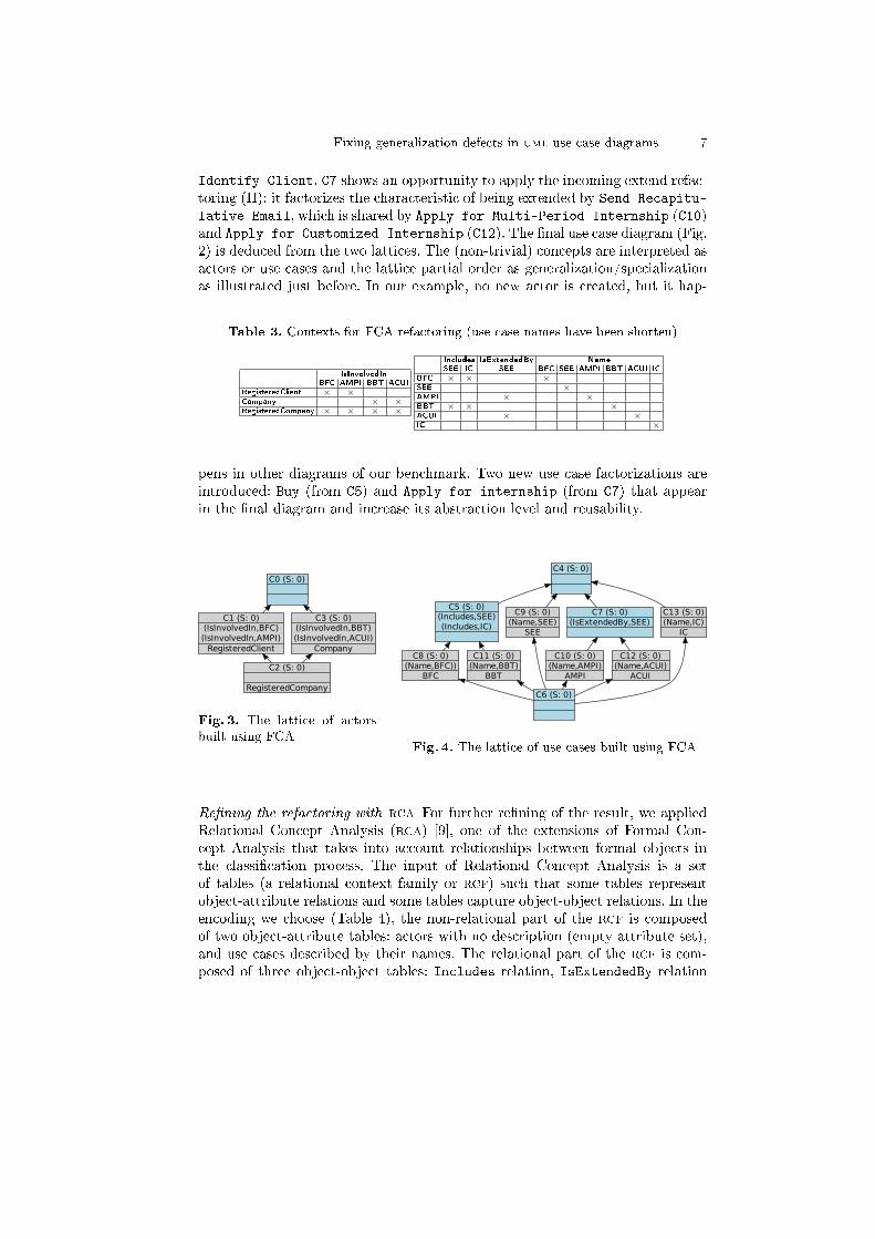
Identify Client. C7 shows an opportunity to apply the incoming extend refac-toring (II): it factorizes the characteristic of being extended by Send Recapitu-
lative Email, which is shared by Apply for Multi-Period Internship (C10)and Apply for Customized Internship (C12). The �nal use case diagram (Fig.2) is deduced from the two lattices. The (non-trivial) concepts are interpreted asactors or use cases and the lattice partial order as generalization/specializationas illustrated just before. In our example, no new actor is created, but it hap-
Table 3. Contexts for FCA refactoring (use case names have been shorten)
IsInvolvedInBFC AMPI BBT ACUI
RegisteredClient × ×Company × ×RegisteredCompany × × × ×
Includes IsExtendedBy NameSEE IC SEE BFC SEE AMPI BBT ACUI IC
BFC × × ×SEE ×AMPI × ×BBT × × ×ACUI × ×IC ×
pens in other diagrams of our benchmark. Two new use case factorizations areintroduced: Buy (from C5) and Apply for internship (from C7) that appearin the �nal diagram and increase its abstraction level and reusability.
C0 (S: 0)
C1 (S: 0)(IsInvolvedIn,BFC)(IsInvolvedIn,AMPI)
RegisteredClient
C2 (S: 0)
RegisteredCompany
C3 (S: 0)(IsInvolvedIn,BBT)(IsInvolvedIn,ACUI)
Company
Fig. 3. The lattice of actorsbuilt using FCA
C4 (S: 0)
C5 (S: 0)(Includes,SEE)(Includes,IC)
C6 (S: 0)
C8 (S: 0)(Name,BFC))
BFC
C9 (S: 0)(Name,SEE)
SEE
C10 (S: 0)(Name,AMPI)
AMPI
C11 (S: 0)(Name,BBT)
BBT
C12 (S: 0)(Name,ACUI)
ACUI
C13 (S: 0)(Name,IC)
IC
C7 (S: 0)(IsExtendedBy,SEE)
Fig. 4. The lattice of use cases built using FCA
Re�ning the refactoring with rca For further re�ning of the result, we appliedRelational Concept Analysis (rca) [9], one of the extensions of Formal Con-cept Analysis that takes into account relationships between formal objects inthe classi�cation process. The input of Relational Concept Analysis is a setof tables (a relational context family or rcf) such that some tables representobject-attribute relations and some tables capture object-object relations. In theencoding we choose (Table 4), the non-relational part of the rcf is composedof two object-attribute tables: actors with no description (empty attribute set),and use cases described by their names. The relational part of the rcf is com-posed of three object-object tables: Includes relation, IsExtendedBy relation

8 Dolques et al.
and IsInvolvedIn relation. The choice of these relations is guided by the refac-toring patterns that we have identi�ed as relevant, and by preliminary experi-ments that highlighted cases where combinatorial explosion occurred.
C0 (S: 0)IsInvolvedIn : C1
IsInvolvedIn : C12IsInvolvedIn : C13
C9 (S: 1)IsInvolvedIn : C2IsInvolvedIn : C5RegisteredClient
C10 (S: 1)
RegisteredCompany
C11 (S: 1)IsInvolvedIn : C6IsInvolvedIn : C7
Company
Fig. 5. The lattice of ac-tors built using RCA
C1 (S: 0)
C2 (S: 0)(Name,BFC)
BFC
C12 (S: 1)Includes : C1Includes : C4Includes : C8
C3 (S: 0)
C4 (S: 0)(Name,SEE)
SEE
C5 (S: 0)(Name,AMPI)
AMPI
C6 (S: 0)(Name,BBT)
BBT
C7 (S: 0)(Name,ACUI)
ACUI
C8 (S: 0)(Name,IC)
IC
C13 (S: 1)IsExtendedBy : C1IsExtendedBy : C4
Fig. 6. The lattice of use cases built using RCA
One lattice is built for each object-attribute table, in our case a lattice foractors, and a lattice for use cases. Those two lattices integrate the attributesand the relations. rca iterates on two successive steps: building of lattices withclassical fca framework (on each object-attribute table concatenated with thecorresponding object-object tables) and integration of the concepts discoveredat the current iteration in the relational part (to be used at the next itera-tion). The integration of the concepts discovered at the current iteration usesscaling operators, here the existential operator has been used. For the integra-tion, an object-object relation (e.g. Includes) is transformed by replacing theobjects which are in the columns by the concepts of the lattice built at thecurrent iteration on these objects. Then a relation is established in the new,existentially scaled, table, between an object and a concept, when the object isin relation with at least one object in the extent of the concept. For example,RegisteredClient IsInvolvedIn BFC in the original relation. Then, when at aniteration BFC is in the extent of a concept, say C12, in the scaled IsInvolvedIn
relation, RegisteredClient is considered as participating in one of the use casesgrouped by C12. A pair (RegisteredClient, C12) is added in the scaled tableIsInvolvedIn. This pair enriches the description of the three actors and at thenext fca step, it is factored out in C0, top of the actor lattice. That highlightsthe opportunity to de�ne a more generalized actor, this opportunity did notappear in the one-step fca building.
At each step, new concepts can appear, as well as new pairs relating thesenew concepts. The process iterates until no new concept or description emerge.Figures 5 and 6 show the �nal lattices. Lattices are interpreted as in the fcaanalysis, adding an interpretation of the references between the two lattices. Theresult of rca improves the result of fca on this example by adding the new,

Fixing generalization defects in uml use case diagrams 9
Table 4. Relational Context Family for RCA refactoring
Nameuse case BFC SEE AMPI BBT ACUI IC
BFC ×SEE ×AMPI ×BBT ×ACUI ×IC ×
Includes BFC SEE AMPI BBT ACUI IC
BFC × ×SEE
AMPI
BBT × ×ACUI
IC
IsExtendedBy BFC SEE AMPI BBT ACUI IC
BFC
SEE
AMPI ×BBT
ACUI ×IC
IsInvolvedIn BFC SEE AMPI BBT ACUI IC
RegisteredClient × ×Company × ×RegisteredCompany × × × ×
actor
RegisteredClient
Company
RegisteredCompany
more general actor (Fig. 7). Furthermore, the interpretation of the concepts isused to interpret the references between lattices. For example, the characteristicisInvolvedIn:C12 which appears in C0 of the actor lattice signals that the actorwhich will be created to interpret C0 will participate in the use case resultingfrom the interpretation of the use case C12, that is the general use case Buy.
Fig. 7. The internship example refactored using RCA
5 Case Study
We present in this section the current implementation of our approach and theresults obtained by running it on di�erent kinds of data.
The Eclipse Modelling Framework (EMF) is a facility from the Eclipse IDEto implement modelling languages and generate tools to manipulate instances ofthose languages from programs. We use in our tool two Eclipse plugins based on

10 Dolques et al.
EMF: UML21 and eRCA2. UML2 is an implementation of UML and thereforeallows us to load, modify and save use case diagrams. eRCA is an implementationof FCA and RCA algorithms which uses EMF to implement contexts and lattices.We have developed a tool implementing both the FCA and RCA approachesfor use case refactoring. For both of them we developed the same three stepsdescribed in Section 4: �rst the tool loads a use case diagram using UML2plugin and encodes it as contexts in eRCA format; second it uses the eRCA toolto generate lattices in eRCA format; �nally lattices are automatically analyzedto create back a use case diagram in the UML2 plugin format and to save it.
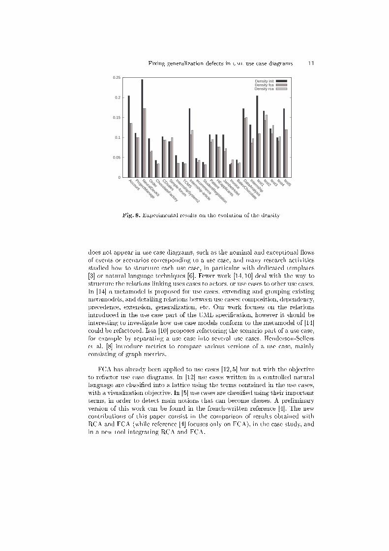
We present here the results obtained using data gathered from di�erentsources such as student projects or UML courses taken from the internet3. Weencoded these diagrams using the UML2 plugin in Eclipse. Then we applied ourtwo processes in all of them and automatically processed the results to comparethem with the original diagrams. We computed the density of the diagram whichis, if we consider the diagram as a graph G = (V,E), the number of edges overthe number of possible edges |E|/|V |2. We assume that the lower density we havethe clearer the diagram is. Of course, this is just indicative. We present in Fig-ure 8 how the density can be changed by our approach on all our data. The last�ve diagrams considered (test1 to test5) are used to test speci�c situations.We see that in most of the diagrams the density is lowered by using FCA andRCA, but with better results for FCA. Density goes down due to the creation ofnew use cases or actors and to the factorization of the relationships. An inversesituation can occur if the number of generalization links created is higher thanthe number of links removed by factorization. This is why FCA seems to bebetter here than RCA, because RCA creates more concepts. Nevertheless, thedensity for RCA usually remains better than the original density. We also seethat density is not improved for the diagram Invoice. Indeed, we assume thateach actor involved in a use case has the same role, so they can be factored intothe same concept. But in the case of this diagram, many actors are involved inthe same use cases but with di�erent roles. This may be allowed depending onthe interpretation of the UML speci�cation, but results in the merging of manyactors into one. By removing those actors and thus not adding new abstractionsamong actors, the density is then increased. This can be partly solved by addingan identi�er for each actor when creating the contexts, but this prevents us to�nd new generalizations of actors since none of them would share in their intentthe same identi�ers.
6 Related Work
Literature dealing with designing use cases is proli�c, but usually concentrateson textual use cases [13, 3], and not on UML use case diagrams. It is generallyadmitted that use cases should be described by quite a lot of information that
1 http://www.eclipse.org/uml2/2 http://code.google.com/p/erca/3 all data available at http://www.lirmm.fr/%7edolques/publications/data/cla10
Fixing generalization defects in uml use case diagrams 11
0
0.05
0.1
0.15
0.2
0.25
Account
ProjectManage
NeuralDevKit
Order
ChocolateFactory
CDsales
Simple-forum
InternshipSystem2
TCMS
Internship-article
ecomm
erce
StudentRegistation
Patient
HEapplicants
JambetHotel
Invoice
BalevChocolate
DataAnalysis
Internship
test1test2
test3test4
test5
Density initDensity fcaDensity rca
Fig. 8. Experimental results on the evolution of the density
does not appear in use case diagrams, such as the nominal and exceptional �owsof events or scenarios corresponding to a use case, and many research activitiesstudied how to structure each use case, in particular with dedicated templates[3] or natural language techniques [6]. Fewer work [14, 10] deal with the way tostructure the relations linking uses cases to actors, or use cases to other use cases.In [14] a metamodel is proposed for use cases, extending and grouping existingmetamodels, and detailing relations between use cases: composition, dependency,precedence, extension, generalization, etc. Our work focuses on the relationsintroduced in the use case part of the UML speci�cation, however it should beinteresting to investigate how use case models conform to the metamodel of [14]could be refactored. Issa [10] proposes refactoring the scenario part of a use case,for example by separating a use case into several use cases. Henderson-Sellerset al. [8] introduce metrics to compare various versions of a use case, mainlyconsisting of graph metrics.
FCA has already been applied to use cases [12, 5] but not with the objectiveto refactor use case diagrams. In [12] use cases written in a controlled naturallanguage are classi�ed into a lattice using the terms contained in the use cases,with a visualization objective. In [5] use cases are classi�ed using their importantterms, in order to detect main notions that can become classes. A preliminaryversion of this work can be found in the french-written reference [4]. The newcontributions of this paper consist in the comparison of results obtained withRCA and FCA (while reference [4] focuses only on FCA), in the case study, andin a new tool integrating RCA and FCA.
12 Dolques et al.
7 Conclusion
UML use case diagrams can be seen as the functional cornerstone of UML mode-ling. In this paper, we proposed an approach to refactor such use case diagramsin order to make them clearer. The principle is to use FCA or RCA in order todetect new abstractions that, when introduced in the diagram, can reduce itsvisual complexity. Using the tool we developed to implement this approach, wecarried on experiments using a set of about 20 use case diagrams to measureits e�ciency in terms of density of relations in the diagram. It results that bothFCA and RCA processes decrease the density of realistic-size use case diagrams,the density obtained with FCA being lower than with RCA. However, RCAdiscovers more abstract use cases or actors that can be relevant. To go furtherin this study, we are studying accurately other metrics, both quantitative asaverage degree, and qualitative, as precision.Acknowledgments. Authors would like to thank L. M. Hakik for a preliminarystudy, K. Bouzroud, I. Dagha, H. El Assam, M. El Asri, and J. Ruizsimarifor their help in the implementation of the current tool, and the anonymousreviewers for their suggestions on evaluation metrics.
References
1. Ambler, S.W.: The Object Primer: Agile Model-Driven Development with UML2.0. Cambridge University Press, New York, NY, USA (2004)
2. Booch, G., Rumbaugh, J., Jacobson, I.: Uni�ed Modeling Language User Guide,chap. 16. Addison-Wesley Prof. (2005)
3. Cockburn, A.: Writing E�ective Use Cases. Addison-Wesley Professional (2000)
4. Dolques, X., Madiha Hakik, L., Huchard, M., Nebut, C., Reitz, P.: Correction desdéfauts de généralisation dans les diagrammes de cas d'utilisation UML. In: Proc.of LMO'10 (Langages et Modèles à Objets). pp. 51�66 (2010)
5. Düwel, S., Hesse, W.: Bridging the gap between use case analysis and class structuredesign by formal concept analysis. In: Proceedings of Modellierung 2000. pp. 27�40.Fölbach-Verlag (2000)
6. Fantechi, A., Gnesi, S., Lami, G., Maccari, A.: Application of linguistic techniquesfor use case analysis. In: IEEE International Conference on Requirements Engi-neering. p. 157. IEEE Computer Society, Los Alamitos, CA, USA (2002)
7. Ganter, B., Wille, R.: Formal Concept Analysis: Mathematical Foundations.Springer (1999)
8. Henderson-Sellers, B., Zowghi, D., Klemola, T., Parasuram, S.: Sizing use cases:How to create a standard metrical approach. In: OOIS. Lecture Notes in ComputerScience, vol. 2425, pp. 409�421. Springer (2002)
9. Huchard, M., Hacene, M.R., Roume, C., Valtchev, P.: Relational concept discoveryin structured datasets. Ann. Math. Artif. Intell. 49(1-4), 39�76 (2007)
10. Issa, A.: Utilising refactoring to restructure use-case models. In: Proc. of the WorldCongress on Engineering, 2007. pp. 523�527. LNCS (2007)
11. Kruchten, P.: The Rational Uni�ed Process: An Introduction, Second Edition.Addison-Wesley Longman Publishing Co., Inc., Boston, MA, USA (2000)

Fixing generalization defects in uml use case diagrams 13
12. Richards, D., Böttger, K., Aguilera, O.: A controlled language to assist conversionof use case descriptions into concept lattices. In: Australian Joint Conference onArti�cial Intelligence. pp. 1�11. LNCS, Springer (2002)
13. Rolland, C., Achour, C.B.: Guiding the construction of textual use case speci�ca-tions. Data Knowl. Eng. 25(1-2), 125�160 (1998)
14. Rui, K., Butler, G.: Refactoring use case models : The metamodel. In: ACSC'03.CRPIT, vol. 16, pp. 301�308. ACS (2003)