Five Gallon Bucket Hydroelectric Generator Build · PDF fileFive Gallon Bucket Hydroelectric...
35
Five Gallon Bucket Hydroelectric Generator Build Manual Sam Redfield Appropriate Infrastructure Development Group Five Gallon Bucket Hydroelectric Generator Build Manual - Version 1 page 1 of 35
-
Upload
phungthuan -
Category
Documents
-
view
235 -
download
3
Transcript of Five Gallon Bucket Hydroelectric Generator Build · PDF fileFive Gallon Bucket Hydroelectric...

Five Gallon Bucket Hydroelectric Generator
Build Manual
Sam RedfieldAppropriate Infrastructure Development Group
Five Gallon Bucket Hydroelectric Generator Build Manual - Version 1
page 1 of 35

Introduction 4
Performance and Specifications 5
Materials 7
Permanent Magnet Alternator and Body of the Generator 7
PVC Pipe and Fittings 7
Threaded Rod and Hardware to Mount PMA to Bucket Lid 7
Threaded Rod and Hardware to Mount Splash Guard to PMA 8
Hardware to Attach the Turbine to the PMA 8
Other Hardware and Materials 8
Tools 8
Safety Equipment 9
PVC Cut List 10
10-24 Threaded Rod Cut List 10
3/8” Threaded Rod Cut List 10
Construction 10
Layout of the Manifold and the 10-24 Threaded Rod Holes for the Bucket Lid 10
Construction of the Manifold 11
Attaching the PMA to the Bucket Lid 15
Construction of the Interior Pipe Stems and PVC Elements 17
Layout and Attachment of the Splash Guard 18
Layout of the Turbine Hub 22
Making the PVC Spoons for the Turbine 23
Attachment of the Turbine Spoons to the Turbine Hub 24
Five Gallon Bucket Hydroelectric Generator Build Manual - Version 1
page 2 of 35

Balancing the Turbine 25
Attachment of the Turbine to the Generator 26
Making the Exit Port on the Bucket of the Generator 27
Electronics 29
The Shunt Load Regulator 29
Attachment of the Shunt Load Regulator to the Generator 34
Conclusion 35
Five Gallon Bucket Hydroelectric Generator Build Manual - Version 1
page 3 of 35
Introduction This build manual provides step by step instructions for the construction of the Five Gallon Bucket Hydroelectric Generator developed by Sam Redfield with the Appropriate Infrastructure Development Group (AIDG) in Guatemala. This manual offers guidance for selecting the tools and materials needed to make the generator, as well as techniques involved in its construction. By design, the materials from which the generator is constructed are extremely common. With the exception of the modified alternator, allthe components used here should be readily available just about anywhere. The generator is experimental. Developed as an effort to address the lack of commercially available small scale hydroelectric generators that are affordable to the average person in developing countries, the generator offers the prospect of clean energy at a relatively modest cost. When compared to the cost of comparably sized photovoltaic, hydroelectric and wind generation systems, the Five Gallon Bucket Generator is competitive and promises to provide cheap clean energy to people who might otherwise not be able to afford it. Another goal in the development of the generator was to address the lack of availability of locally produceable clean energy systems that can be manufactured by small scale workshops in developing countries. The generator is easy to build and easy to maintain. While not as efficient as commercially available pico-hydro systems, the generator offers a simple solution that can be manufactured locally and serviced by artisans with limited resources and skills. As the generator is configured in this manual, a minimum of 30 feet of head and a flow of 26 gallons per minute is required, in order to reach the 13.7 volts needed for 12 volt charging. In addition tothe generator, a penstock and trash rack must be constructed. We used 2” PVC pipe fitted with a ball valve at each end of the penstock, and another five gallon bucket fitted with hardware cloth at the mouth as a trash rack at the head of the penstock. For electronics, a shunt load regulator1, battery(s) and an inverter are needed. The shunt load regulator is to keep the battery(s) from over charging. The shunt load regulator that we used was designed for photovoltaic systems and can be built easily and cheaply. We used one conventional car battery for economy during our trials, and used only the power that was produced in real time. For budgets that allow it, deep cycle batteries can be purchased in order to obtain a larger capacity system. The inverter allows conventional 110 volt appliances to be powered from the battery(s). The alternator that is employed in this manual is a permanent magnet alternator (PMA) but there are many options that can be used in the generator. Choices range from running a DC motor backwards to using a stepper motor removed from an old copy machine. The amount of energy that can be produced from the generator is largely dependent upon the motor/alternator. Think carefully about how much power you need and decide on a scheme that will provide the power required.
Five Gallon Bucket Hydroelectric Generator Build Manual - Version 1
page 4 of 35
1 The components for the shunt load regulator may or may not be available locally depending upon the
country that you live in or the remoteness of your location.

The PMA used in this manual is manufactured in the United States and is somewhat expensive. If you are outside the United States, it will have to be shipped to you. To address this issue, we are in the process of developing a PMA made from the alternator of Toyota's 22R engine. This alternator, produced by Nippondenso for Toyota, is perhaps the most common alternator in the world. Once the Toyota based PMA is finished the only item potentially requiring importation will be the neodymium magnets used in the alternator conversion. A later publication will address the construction of the Toyota/Nippondenso PMA. Before you begin, you should have in hand whatever alternator or motor that you are going to use in the generator. The design and construction of the generator will be different depending upon which alternator/motor that you use. In this manual we will be using the SC24 PMA from Hydrogen Appliances in the United States; if you choose to use another PMA or DC motor or another scheme, you will need to adjust your approach in the generator’s construction. The generator is designed to be built in a modestly equipped workshop by artisans with basic carpentry and plumbing skills. Beyond common hand tools, at minimum you will need access to a table saw. We used a drill press and motorized mitre saw for ease and accuracy of construction, but if care is given to precision, a hand drill and hand saw can be used instead. Made almost entirely from PVC pipe, the generator is symmetrical in construction, so you will be cutting several of the same size components. We suggest that you cut all of your same size components at the same time for accuracy and efficiency. Layout for the holes drilled in the various components of the generator are also symmetrical and should be done at the same time. Care should be given at each step of the generators construction as small differences in the size of each component will amplify over time creating a less than perfect final product. The first step in the construction of the generator is to source the tools, materials and components of the generator. If you cannot source all the tools and materials listed in the materials list, you will have to find alternatives. For example, there are subtle differences in five gallon buckets. Specifically, the bucket lids available in your location may be configured differently than the ones used in this manual. The other materials should be available at most average sized hardware stores. You may have to go to a plumbing store for the PVC components, or visit a few hardware stores to complete the list, but everything should be readily available in most places. After acquiring all the materials and components listed in the materials list the PVC pipe and the threaded rod must be cut to length. Again, it is important that you are accurate in your cuts and that you make all of your same size cuts at the same time.
Performance and Specifications
Preliminary testing was performed on the generator to determine its performance characteristics. Different penstock heads were simulated using a hydro test bench that pumped water through the generator. 2” pipe was used for the penstock. A relationship between head and open circuit voltage (where no load is connected to the alternator) was determined and is shown in Figure 1.
Five Gallon Bucket Hydroelectric Generator Build Manual - Version 1
page 5 of 35

Figure 1 – Open Circuit Voltage vs Head
From Figure 1 it can be seen that a head of approximately 9m (28ft) is required to reach the minimum open circuit voltage of 13.7V required for 12V charging. However, if the generator is operated at heads greater than this, more current will be generated and charging will occur at a faster rate.
The maximum head simulated with the test bench was 27m (~90 ft). At this head, the generator had the following performance characteristics:
Flow Rate: 185 Lpm (~50 gpm)Open Circuit Voltage: 51 VoltsRPM (Open Circuit): 1300 RPM’sMaximum Power: 90 WattsWater velocity at nozzles: 19 m/s
The power of the generator is dependent on the load that is connected to the system. The maximum power of 90W was achieved when a resistive load of 5 ohms was connected to the generator. As an example, a power of this magnitude is sufficient to power three 30W UV water treatment systems. Alternatively, it could power up to 80 one watt LED lights (dependent on line losses and draw from the inverter used).
More power can be generated from the system at higher heads. However, the generator has not been tested at these higher head and flow rates and the structural integrity of
Five Gallon Bucket Hydroelectric Generator Build Manual - Version 1
page 6 of 35
the turbine is unknown. Reliability testing is currently underway to determine the potential for fatigue failures when operating at high heads and for long periods of time.
Materials
Permanent Magnet Alternator and Body of the Generator• One Supercore Permanent Magnet Alternator with fan assembly
• One five gallon bucket
• Three five gallon bucket lids
PVC Pipe and Fittings• Four 3/4” 90 degree couplings
• Three 3/4” T’s
• Eight 3/4” straight couplings
• Four 3/4” to 1/2” adaptors
• One 3/4” to 2” adaptor
• Eleven 3/4” x 1 3/8” PVC pipe
• Four 3/4” x 3 1/4” PVC pipe
• Four 1/2” 90 degree couplings*
• Four 1/2” Plugs*
• Eight 1/2” x 1 3/8 PVC pipe
• Twelve 1/2” 45 degree couplings
• Two 2” straight couplings
• One 2” x 1 3/4” PVC pipe
• PVC cement
*Note: For generators made in areas where 1/2” glue plugs are not available, substitute the four 1/2” 90
degree couplings with four 1/2” 90 degree couplings threaded on one side, and the four 1/2” glue
plugs with four 1/2” threaded plugs.
Threaded Rod and Hardware to Mount PMA to Bucket Lid
• Four 10-24 Pieces of threaded rod 4 ! ” long
• Eight 3/16” x 1 1/4” Fender Washers
Five Gallon Bucket Hydroelectric Generator Build Manual - Version 1
page 7 of 35

• Eight 10-24 lock washers
• Eight 10-24 washers
• Twelve 10-24 nuts
Threaded Rod and Hardware to Mount Splash Guard to PMA
• One 3/8” piece threaded rod at 3”
• One 3/8” piece threaded rod at 1 3/4”
• Four 3/8” fender washers
• Four 3/8” nuts
• Eight 3/8” lock washers
• Eight 3/8” washers
Hardware to Attach the Turbine to the PMA
• Four washers 3/4” ID, 1 3/4” OD.
Other Hardware and Materials
• 32 Pop Rivets - 1/8” diameter, 1/4” long
• Silicon Caulk
• Two 2” Straight Couplings
• One 2” PVC pipe 1 3/4” long
Tools
• Drill Press
• Power Hand Drill
• Table Saw
• Electric Mitre Saw
• Two Plywood Saw Blades (one for table saw and one for electric mitre saw)
• Hack Saw or metal cutting blade for the electric mitre saw
• Hole Saws
-7/8” hole saw for pipe stems in splash guard
-1 1/8” hole saw for manifold in manifold assembly
Five Gallon Bucket Hydroelectric Generator Build Manual - Version 1
page 8 of 35

-2 1/4” hole saw for the exit port in the bucket
• Drill bits
-1/16” for pilot holes
-1/8” for pilot holes and pop rivet holes
-3/16” for 10-24 threaded rod in manifold assembly
-1/4” for pilot holes
-5/16” for orifice in nozzle
-3/8” for pilot holes
-1/2” for pilot hole in turbine, outside diameter of orifice in nozzle and 3/8” threaded rod in splash guard
-5/8” for center hole in turbine (a precision bit is best)
• Utility Knife
• Compass
• Ruler
• Ball Point Pen (that fits in compass)
• Pencil
• Awl, or similar marking tool
• Pop Rivet Gun
• Channel Locks
• 120 Sand Paper
• Wrenches
-15/16” open ended for PMA shaft nut
-5/16 allen key for PMA shaft
-9/16” open ended for 3/8” nuts
-3/8” open ended for 10-24 nuts
-1/2” open ended for negative PMA lead
-7/16” open ended for positive PMA lead
Safety Equipment
• Safety Goggles
• Ear Protection
• Respirator
Five Gallon Bucket Hydroelectric Generator Build Manual - Version 1
page 9 of 35

PVC Cut List If you use the motorized mitre saw to cut the PVC, mount the plywood blade in the saw backwards for cutting.
• Eleven 3/4” x 1 3/8” PVC pipe
• Four 3/4” x 3 1/4” PVC pipe
• Eight 1/2” x 1 3/8” PVC pipe
• Eight 1/2” 45 degree couplings (these couplings are cut in half with the table saw at roughly
1/2” to make up the sixteen spoons of the turbine)
10-24 Threaded Rod Cut List
• Four 10-24 Pieces of threaded rod 4 ! ” long
3/8” Threaded Rod Cut List
• One 3/8” piece threaded rod at 3”
• One 3/8” piece threaded rod at 1 3/4”
Construction Layout of the Manifold and the 10-24 Threaded Rod Holes for the Bucket Lid
The manifold is built into the lid of the bucket that covers the generator. You will drill four holes in the bucket lid that will receive the four supply lines running from the manifold into the bucket. In addition, you will drill four holes that receive the 10-24 threaded rod that attaches the permanent magnet alternator to the lid of the bucket.
With the top of the bucket lid facing up, find the center of the lid and make a small registration mark with an awl. Once this mark is made, use a ruler to make a line transecting the registration mark across the entire bucket lid. Once this line is drawn, take a piece of paper or something else that you know is square and make another line perpendicular to the first line from the registration point in the center of the bucket. Continue that line on the other side of the center registration point until you have two perpendicular lines centered on the registration point that spans the entire top of the bucket lid.
Five Gallon Bucket Hydroelectric Generator Build Manual - Version 1
page 10 of 35

Once you have drawn these layout lines, measure 4 1/4” from the center registration mark on one of your lines and make a mark. Take a compass with a ball point pen in it and span the distance from the center registration mark to the mark at 4 1/4”. Take the compass and make a mark on the three remaining layout lines until you have a mark on each line equal-distant from the center registration mark. These marks around the perimeter of the bucket lid will be the center marks for the four holes that receive the PVC manifold. Using an awl, make registration marks at each of these points.
At this time you should make the registration marks for the holes that receive the 10-24 threaded rod that secures the permanent magnet alternator to the lid of the bucket. Measure 2 13/16” from the center registration point on one of the layout lines. Use a compass to span the distance from the center registration point to the mark on the layout line you just made. Use the compass to make a mark on the three remaining layout lines until you have a mark on each of the four lines equal-distant from the center registration mark. These marks will be the center mark for the holes that receive the 10-24 threaded rod that attaches the permanent magnet alternator to the bucket lid. Using an awl, make registration points at each of these marks.
Using a 1/16” drill bit, make pilot holes at each of the eight registration points on the layout lines of the bucket lid. There will be four holes to receive PVC and four holes to receive 10-24 threaded rod. Moving to a slightly larger bit, enlarge the eight pilot holes by drilling them out with a 1/8” drill bit. Using a 1 1/8” hole saw, drill out the four pilot holes closest to the outside perimeter of the bucket lid. These holes will receive the manifold. Using a 3/16” drill bit, drill out the pilot holes closest to the center of the bucket lid to receive the 10-24 threaded rod. The bucket lid is now ready to receive the PVC manifold and the 10-24 threaded rod to attach the permanent magnet alternator to the lid of the bucket.
Construction of the Manifold
For the construction of the manifold you will need the prepared bucket lid made in the previous section, PVC cement and the following PVC couplings, fittings and pipe lengths:
Five Gallon Bucket Hydroelectric Generator Build Manual - Version 1
page 11 of 35
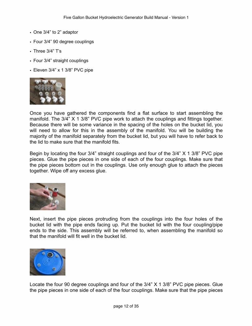
• One 3/4” to 2” adaptor
• Four 3/4” 90 degree couplings
• Three 3/4” T’s
• Four 3/4” straight couplings
• Eleven 3/4” x 1 3/8” PVC pipe
Once you have gathered the components find a flat surface to start assembling the manifold. The 3/4” X 1 3/8” PVC pipe work to attach the couplings and fittings together. Because there will be some variance in the spacing of the holes on the bucket lid, you will need to allow for this in the assembly of the manifold. You will be building the majority of the manifold separately from the bucket lid, but you will have to refer back to the lid to make sure that the manifold fits.
Begin by locating the four 3/4” straight couplings and four of the 3/4” X 1 3/8” PVC pipe pieces. Glue the pipe pieces in one side of each of the four couplings. Make sure that the pipe pieces bottom out in the couplings. Use only enough glue to attach the pieces together. Wipe off any excess glue.
Next, insert the pipe pieces protruding from the couplings into the four holes of the bucket lid with the pipe ends facing up. Put the bucket lid with the four coupling/pipe ends to the side. This assembly will be referred to, when assembling the manifold so that the manifold will fit well in the bucket lid.
Locate the four 90 degree couplings and four of the 3/4” X 1 3/8” PVC pipe pieces. Glue the pipe pieces in one side of each of the four couplings. Make sure that the pipe pieces
Five Gallon Bucket Hydroelectric Generator Build Manual - Version 1
page 12 of 35

bottom out in the couplings. Use only enough glue to attach the pieces together. Wipe off any excess glue. Put these pieces to the side for now.
Locate one of the 3/4” T’s, and three of the 3/4” X 1 3/8” PVC pipe pieces. Glue one of the 3/4” X 1 3/8” PVC pipes into each opening of the T. Make sure that the pipe pieces bottom out in the couplings. Use only enough glue to attach the pieces together. Wipe off any excess glue. Put this piece aside for now.
We are now ready to dry assemble the manifold. To make sure that everything fits together well, the manifold should be assembled first without glue; use a little soap to ensure an easy removal. All of the components of the manifold need to fit in the bucket lid without pinching in the holes and the 3/4” straight couplings need to be as close as perpendicular to the bottom of the lid as possible. In addition, all the components of the manifold should be as evenly spaced as possible, relative to each other. Vertical and horizontal elements of the manifold should be as perpendicular to each other as possible. Once dry assembled, small registration marks can be made on all the pending glue joints with an awl so that when the manifold is assembled with glue it will fit into the bucket lid well. Remember to wash off the soap after dry fitting. Locate the T that you made earlier with the 1 3/8” pipe ends. Take your two remaining T’s and fit the base of the T’s together with the T that you built earlier, fitting the two new T’s to the 1 3/8” pipe ends that are on the top of the T.
Locate the four 90 degree fittings that you made up earlier with the 1 3/8” pipe ends and fit those to the top of the two remaining T ends in the two new T’s.
Five Gallon Bucket Hydroelectric Generator Build Manual - Version 1
page 13 of 35

Locate the bucket lid with the 3/4” straight couplings and the 1 3/8” pipe ends protruding from the holes in the top. Fit the remaining four unused ends of the four 90 degree fittings to the 1 3/8” pipe ends protruding from the top of the bucket lid.
Fit the 3/4” to 2” adapter to the bottom of the 1 3/8” pipe end in the T at the center of the manifold.
At this point, you should adjust the manifold for symmetry and make sure that the 3/4” couplings protruding from the bottom of the bucket lid are perpendicular to the bottom of the lid. This should be done on a flat surface so that the 3/4” couplings end up on the same plane when you are done. Once you are satisfied with the condition of the manifold, make registration marks at each of the glue joints marking the right location for gluing. You should mark both the position of the couplings relative to each other and the stop point on the pipe ends for gluing.
When the manifold is ready to be glued, disassemble the components. Glue all the components together with the exception of the four 1 3/8” pipe ends protruding from the top of the bucket lid and the 3/4” to 2” adapter. Use a flat surface for gluing the manifold together so that when you attach the manifold to the bucket the 90 degree couplings will all be on the same plane.
Five Gallon Bucket Hydroelectric Generator Build Manual - Version 1
page 14 of 35

Next, glue the manifold to the 1 3/8” pipe ends protruding from the top of the bucket lid. Press hard so that the bucket lid is pinched between the 3/4” straight coupling and the 3/4” 90 degree coupling. Use a flat surface for gluing so that the 3/4” straight couplings on the bottom of the lid are on the same plane.
Finally, glue the 3/4” to 2” adaptor to the T at the center of the manifold.
Attaching the PMA to the Bucket Lid
This section covers the attachment of the permanent magnet alternator to the bucket lid.The PMA is attached to the lid of the bucket just inside the manifold assembly with 10-24 threaded rod. Before you begin, locate the threaded rod and hardware listed in the
materials section.
• Four 10-24 Pieces of threaded rod 4 ! ” long
• Eight 3/16” x 1 1/4” Fender Washers
• Eight 10-24 lock washers
• Eight 10-24 washers
• Twelve 10-24 nuts
Five Gallon Bucket Hydroelectric Generator Build Manual - Version 1
page 15 of 35

Find and remove the four screws that hold the front and the back of the alternator together.
Thread the four pieces of 10-24 threaded rod into the four holes that you removed the screws from. Screw the threaded rod into the holes until there is 2 5/8” protruding from the back of the alternator.
Thread on a washer, lock washer and nut onto each of the threaded rods. Tighten the nuts so that the threaded rod is securely attached to the PMA.
Thread an additional nut and a fender washer onto each of the four threaded rods leaving 1 15/16” of threaded rod between the nut that attaches the threaded rod to the PMA and the nut and fender washer.
Push the rest of the threaded rod of the four threaded rods above the fender washer through the holes drilled earlier in the bucket lid manifold assembly. Attach a fender
Five Gallon Bucket Hydroelectric Generator Build Manual - Version 1
page 16 of 35

washer, lock washer and nut. Tighten. You may have to adjust the threaded rod a few times until the PMA hangs evenly on the bucket lid manifold assembly. There should be 1” between the bottom of the bucket lid manifold assembly and the back of the PMA.
Construction of the Interior Pipe Stems and PVC Elements
Once the manifold is complete and attached to the bucket lid and the PMA is attached to the bucket lid manifold assembly, you can begin plumbing the inside of the bucket. Covered in this section will be the four 3/4” x 3 1/4” pipe stems, the four straight 3/4” couplings and the 3/4” to 1/2” step down adapters.
Locate the following PVC pipe and fittings:
• Four 3/4” x 3 1/4” PVC pipe
• Four 3/4” couplings
• Four 3/4” to 1/2” adaptors
Glue the four 3/4” X 3 1/4” PVC pipe stems into the four 3/4” straight couplings on the bottom of the bucket lid manifold assembly. Make sure that they seat all the way into the couplings. On the other end of the 3/4 X 3 1/4” PVC pipe stems, glue the remaining four 3/4” straight couplings. Make sure that they seat all the way on to the pipe. Glue the four 3/4” to 1/2” adapters into the four 3/4” couplings. Make sure that the four 3/4” to 1/2” adaptors bottom out in the 3/4” couplings.
Five Gallon Bucket Hydroelectric Generator Build Manual - Version 1
page 17 of 35

Layout and Attachment of the Splash Guard
The splash guard is made from a bucket lid. The layout of the splash guard is similar to that of the bucket lid manifold assembly in that there are four holes around the perimeter to receive the nozzle assemblies. As in the bucket lid manifold assembly, the layout is from a central registration point in the middle of the lid. The splash guard is pinched between the nozzle assemblies and the four 3/4” to 1/2” adaptors at the end of the 3/4” X 3 1/4” pipe stem assemblies. The holes in the lid are smaller to receive the 1/2” pipe that makes up the nozzle assembly but the process of laying out the holes is much the same. In addition, there are two 3/8” holes made to bolt the splash guard to the PMA. Finally, there is a 4” hole in the center of the splash guard to allow the fan assembly to cool the PMA. To make the splash guard fit inside the bucket, the lid is trimmed to a smaller diameter
Locate the threaded rod and hardware to mount the splash guard to the PMA.
• One bucket lid
• One 3/8” piece threaded rod at 3”
• One 3/8” piece threaded rod at 1 3/4”
• Four 3/8” fender washers
• Four 3/8” nuts
• Eight 3/8” lock washers
• Eight 3/8” washers
Begin by laying out the holes to receive the four 3/4” x 3 1/4” pipe stem assemblies. With the top of the bucket lid facing up, find the center of the bucket lid and make a small registration mark with an awl. Once this mark is made, use a ruler to make a line transecting the registration mark across the entire bucket lid. Once this line is drawn, take a piece of paper or something else that you know is square and make another line perpendicular to the line from the registration point in the center of the bucket. Continue that line on the other side of the registration point until you have two perpendicular lines centered on the registration point that spans the entire top of the bucket lid.
Five Gallon Bucket Hydroelectric Generator Build Manual - Version 1
page 18 of 35

Once you have drawn these layout lines, measure 4 1/4” from the center registration mark on one of your lines and make a mark. Take a compass and span the distance from the center registration mark to the mark at 4 1/4” that you just made. Take the compass and make a mark on the three remaining layout lines until you have a mark on each line equal-distant from the center registration mark. These marks around the perimeter of the bucket lid will be the center marks for the holes that receive the 3/4” x 3 3/4” pipe stems. Using an Awl make registration marks at each of these points.
Using a 1/16” drill bit, make pilot holes at each of the four registration points on the layout lines of the bucket lid. Moving to a slightly larger bit, enlarge the four pilot holes by drilling them out with a 1/8” drill bit. Using a 7/8” hole saw, drill out the four pilot holes to receive the pipe stems.
The next step is to lay out the holes to receive the 3/8” threaded rod to bolt the splash guard to the PMA mounting flanges. These holes are equal-distance from the center of the splash guard. The holes for the 3/8” threaded rod in the splash guard are staggered at 45 degrees to the pipe stem holes. To find 45 degrees, use a square or fold a piece of paper at 45 degrees. Make a new layout line at 45 degrees to the layout lines that were made for the pipe stems. Measure 3 5/16” from the center registration point. Using the compass, span the distance from the center registration mark to the mark on the layout line at 3 5/16”. Using the compass, transpose the mark to the other side of the layout line from the center registration mark. Using an awl, make registration points for the two holes to be drilled to receive the 3/8” threaded rod. Use a 1/16” drill bit to make pilot holes for the threaded rod. Enlarge the pilot holes with a 1/8” drill bit, followed by a 1/4” drill bit. Drill out the holes at 1/2” to receive the 3/8” threaded rod.
Five Gallon Bucket Hydroelectric Generator Build Manual - Version 1
page 19 of 35
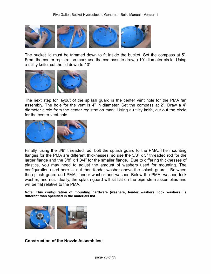
The bucket lid must be trimmed down to fit inside the bucket. Set the compass at 5”. From the center registration mark use the compass to draw a 10” diameter circle. Using a utility knife, cut the lid down to 10”.
The next step for layout of the splash guard is the center vent hole for the PMA fan assembly. The hole for the vent is 4” in diameter. Set the compass at 2”. Draw a 4” diameter circle from the center registration mark. Using a utility knife, cut out the circle for the center vent hole.
Finally, using the 3/8” threaded rod, bolt the splash guard to the PMA. The mounting flanges for the PMA are different thicknesses, so use the 3/8” x 3” threaded rod for the larger flange and the 3/8” x 1 3/4” for the smaller flange. Due to differing thicknesses of plastics, you may need to adjust the amount of washers used for mounting. The configuration used here is: nut then fender washer above the splash guard. Between the splash guard and PMA: fender washer and washer. Below the PMA: washer, lock washer, and nut. Ideally, the splash guard will sit flat on the pipe stem assemblies and will be flat relative to the PMA.
Note: This configuration of mounting hardware (washers, fender washers, lock washers) is different than specified in the materials list.
Construction of the Nozzle Assemblies:
Five Gallon Bucket Hydroelectric Generator Build Manual - Version 1
page 20 of 35

The nozzle assemblies are composed of two types of couplings per nozzle: A 1/2” 90 degree coupling and a 1/2” 45 degree coupling. In addition, there are two pieces of 1/2 x1 3/8” PVC pipe and a 1/2” plug per nozzle. The 1/2” plugs are drilled out to make the nozzles.
Locate the following PVC pipe and fittings:
• Four 1/2” 45 degree
• Four 1/2” 90 degree
• Four 1/2” Plugs
• Eight 1/2” x 1 3/8 PVC pipe
Find the four 1/2” 45 degree couplings. In each 45 degree coupling glue a
1/2” x 1 3/8” PVC pipe in each end. Make sure that the pipe seats all the way into
the coupling. Wipe off any excess glue.
Use an awl to mark the center point of the four 1/2” plugs*. Drill a pilot hole starting with a 1/32” drill bit and enlarge the pilot hole by using larger bits at a rate of 1/16” per bit, until you have reached 1/4” diameter. Use a 5/16” bit to drill out the nozzle orifices. Finally, use a 1/2” drill bit to enlarge the the outside of the nozzle orifices so that the orifices are 5/16 in diameter on the inside and 1/2” on the outside. The rim of the nozzles should be only about 1/16 thick.
Five Gallon Bucket Hydroelectric Generator Build Manual - Version 1
page 21 of 35

*Note: Glue Plugs for 1/2 PVC are not available everywhere. In Guatemala, where this generator was built, glue plugs are not available. However, threaded plugs are, as are 1/2” 90 degree couplings with threads on one end. Unfortunately, the plugs do not seat all the way down into the couplings as is required by the generator design. The fix used is to cut all but 3/8” of the threads off of the plug and thread the plug into the 1/2” 90 degree coupling using Teflon tape to seal the threads.
The nozzle assemblies are held together with friction. They need to be periodically cleaned out and adjusted so no glue is used to hold them together. A very thin piece of material can be wedged between the couplings and the pipe to keep them firmly together.
Attach the 45 degree coupling into the 90 degree coupling with the plug in it in each of the four nozzle assemblies. Insert the nozzle assemblies into the 1/2” adaptors of the splash guard. The nozzle assemblies will be adjusted later to find the “sweet spot” discussed later.
Layout of the Turbine Hub
The turbine hub is made from the lid of a five gallon bucket. It is 4” in diameter. It is divided into 16 layout lines from the center of the hub to receive 16 PVC spoons made from eight 1/2” 45 degree couplings cut in half.
Locate a bucket lid.
Set the compass for 2” and draw a 4” circle from the registration point. This is the outside diameter of the hub. Cut out the hub with a utility knife.
Five Gallon Bucket Hydroelectric Generator Build Manual - Version 1
page 22 of 35

From the registration point, divide the hub into 16 layout lines. This can be accomplished by dividing the hub into 4 then 8 then 16 layout lines. Try to be as accurate with this as possible as it will effect the balance of the turbine. Next, set the compass for 9/16” from the center registration point and draw a circle with a diameter of 1 1/8”. The intersection of this circle and the layout lines will be where the PVC spoons end.
Making the PVC Spoons for the Turbine
The sixteen spoons for the turbine are made from eight 1/2” 45 degree PVC couplings cut in half. The eight 1/2” 45 degree couplings are cut down with a table saw. The finished width of the spoons is a little less than 1/2”. These spoons are then pop riveted to the hub made in the previous section.
Locate the eight 1/2” 45 degree PVC couplings.
Mount a plywood blade backwards in the table saw. Set the fence to cut the coupling exactly in half and the blade at 1 3/4” in height. The blade should be set normally at 90 degrees to the table. With the curved section of the 1/2” 45 degree coupling facing down run the coupling through the saw. To accomplish this, use a piece of 1/2” PVC pipe inserted into the coupling as a push stick.
Five Gallon Bucket Hydroelectric Generator Build Manual - Version 1
page 23 of 35

Once the spoons have been made, take pencil and make a layout line on the inside of the spoons on one side 1/8” in from the edge.
Next, using the awl make a registration mark at 1/4” in and 5/8” in from the end of the spoon on the layout line. Holding the spoon on a flat surface and using the top of the spoon as a guide for drilling, make a pilot hole at each of these marks with a 1/32” drill. Finally drill out the pilot holes with a 1/8” drill bit.
Attachment of the Turbine Spoons to the Turbine Hub
The spoons for the turbine are pop riveted from the back of the hub, through the hub and through the spoons.
Find the following materials:
• Hub for the turbine
• 32 Pop Rivets - 1/8” diameter, 1/4” long
• 16 spoons made from PVC
Five Gallon Bucket Hydroelectric Generator Build Manual - Version 1
page 24 of 35

The point where the layout lines and the circle drawn on the hub meet is where the spoons end.
The spoons are attached one by one to the turbine with pop rivets. Because there will be subtle differences in the holes in the spoons, the layout on the hub is based upon the marks made earlier on the hub, not on the holes drilled in the spoons. Hold the spoon in position at the intersection of one of the layout lines and the circle drawn at 1 1/8”. Using the holes drilled in the spoon, drill through the first hole in the spoon into the hub using the layout lines and circle as a guide. Drill through one hole on the spoon, pop rivet it in from the back of the hub and then drill through the other hole in the spoon and pop rivet it in. The first attachment with the pop rivet will insure that the next pop rivet in the spoon will be lined up. Attach the spoons one by one until all the spoons are in place. Be careful. If you don’t hold the spoons in the exact right place based upon the layout lines, you will have to make a new hub. You might want to practice this on a scrap as it is somewhat difficult.
Balancing the Turbine
Because the turbine is handmade it may require balancing.
Locate the tube of caulk.
Balance the turbine on an awl at the center registration mark. If the turbine balances well on the awl you are done. If the turbine tips to one side or the other, you will have to counterbalance it. Squeeze a bit of caulk on the hub of the turbine on the opposite side
Five Gallon Bucket Hydroelectric Generator Build Manual - Version 1
page 25 of 35

of the side that is tipping down. Add or subtract caulk until the turbine balances on the awl.
Attachment of the Turbine to the Generator
Find the following materials:
• Fan assembly
• Four washers 3/4” ID, 1 3/4” OD
• The turbine
• The factory spacer
• The retention nut
Find the center registration mark on the turbine. Using a 1/32” drill bit, drill a pilot hole through the registration point. Work your way up, using a 1/8”, 1/4”, 3/8”, 1/2” bits until
you reach 5/8”. Care should be given to this, as if you get it wrong you will have to build a new turbine. If for some reason your center hole starts to drift off center, you can go larger than 5/8” and center the turbine by eye to the shaft. For best results use a 5/8” precision bit
Remove the pulley from the PMA and discard. Keep the factory spacer under the pulley and the retention nut. Place the the spacer on the shaft of the PMA followed by two of the 3/4” ID, 1 3/4” OD washers. Place the fan assembly onto the shaft. place another of the 3/4”
Five Gallon Bucket Hydroelectric Generator Build Manual - Version 1
page 26 of 35
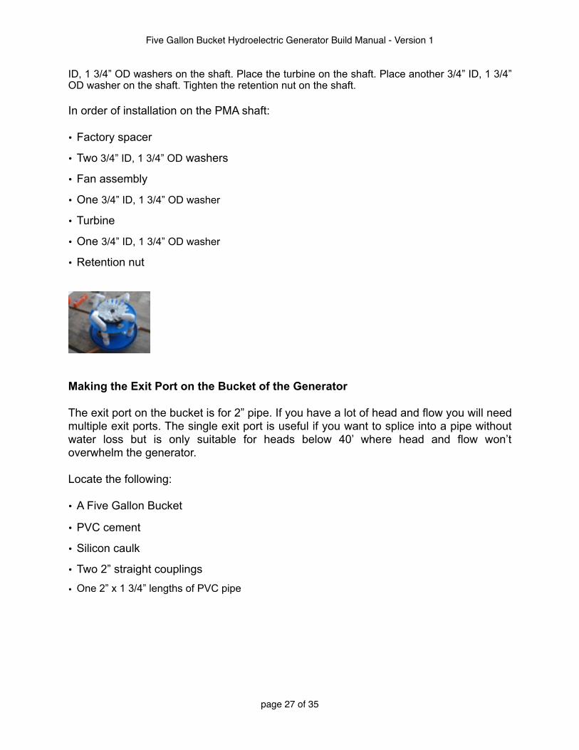
ID, 1 3/4” OD washers on the shaft. Place the turbine on the shaft. Place another 3/4” ID, 1 3/4” OD washer on the shaft. Tighten the retention nut on the shaft.
In order of installation on the PMA shaft:
• Factory spacer
• Two 3/4” ID, 1 3/4” OD washers
• Fan assembly
• One 3/4” ID, 1 3/4” OD washer
• Turbine
• One 3/4” ID, 1 3/4” OD washer
• Retention nut
Making the Exit Port on the Bucket of the Generator
The exit port on the bucket is for 2” pipe. If you have a lot of head and flow you will need multiple exit ports. The single exit port is useful if you want to splice into a pipe without water loss but is only suitable for heads below 40’ where head and flow won’t overwhelm the generator.
Locate the following:
• A Five Gallon Bucket
• PVC cement
• Silicon caulk
• Two 2” straight couplings
• One 2” x 1 3/4” lengths of PVC pipe
Five Gallon Bucket Hydroelectric Generator Build Manual - Version 1
page 27 of 35
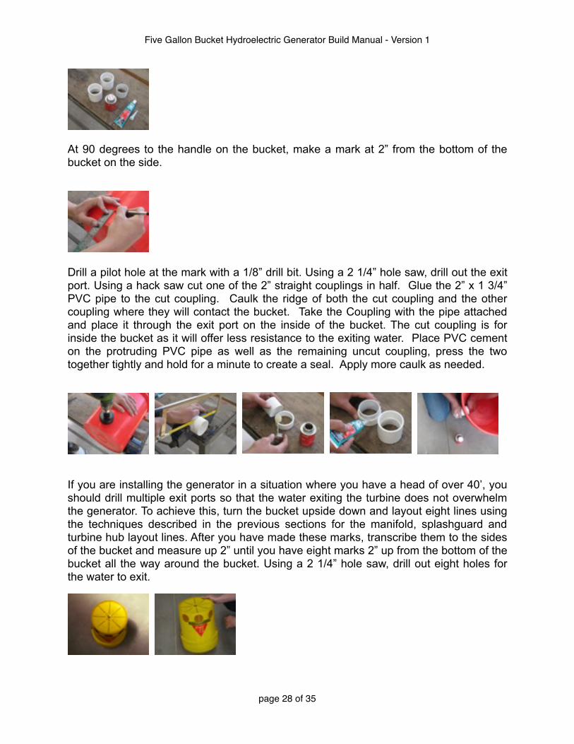
At 90 degrees to the handle on the bucket, make a mark at 2” from the bottom of the bucket on the side.
Drill a pilot hole at the mark with a 1/8” drill bit. Using a 2 1/4” hole saw, drill out the exit port. Using a hack saw cut one of the 2” straight couplings in half. Glue the 2” x 1 3/4” PVC pipe to the cut coupling. Caulk the ridge of both the cut coupling and the other coupling where they will contact the bucket. Take the Coupling with the pipe attached and place it through the exit port on the inside of the bucket. The cut coupling is for inside the bucket as it will offer less resistance to the exiting water. Place PVC cement on the protruding PVC pipe as well as the remaining uncut coupling, press the two together tightly and hold for a minute to create a seal. Apply more caulk as needed.
If you are installing the generator in a situation where you have a head of over 40’, you should drill multiple exit ports so that the water exiting the turbine does not overwhelm the generator. To achieve this, turn the bucket upside down and layout eight lines using the techniques described in the previous sections for the manifold, splashguard and turbine hub layout lines. After you have made these marks, transcribe them to the sides of the bucket and measure up 2” until you have eight marks 2” up from the bottom of the bucket all the way around the bucket. Using a 2 1/4” hole saw, drill out eight holes for the water to exit.
Five Gallon Bucket Hydroelectric Generator Build Manual - Version 1
page 28 of 35

Finding the Sweet Spot:
Despite our best efforts to make a uniform design that can be reproduced exactly, the generator will have some variations depending upon which brand of PVC that you use, the type of bucket that you can get etc. To this end, the nozzle assemblies are adjustable. The 90 degree and the 45 degree couplings can rotate so that you can find the best place to hit the turbine. This is accomplished by trial and error and one must adjust the nozzles, measure power produced and adjust again until the maximum power that is available is found. Once you have found the sweet spot, mark the nozzle assembly with an awl so that if it falls out of adjustment you can find it again. As a general rule you want to adjust the nozzles so that they are as close to the spoons as possible.
Electronics
The Shunt Load Regulator
Variously called a shunt load regulator, dump load regulator or charge controller, the shunt load regulator in a charging system keeps the battery from the damage of overcharging. Below is a solar charge controller design used with permission from Home Power Magazine. It works well as a shunt load regulator for the generator. Instead of regulating the output of a solar panel you will use this controller to regulate the output of the bucket generator. Following the schematic is a description of our method of waterproofing and mounting the regulator to the generator.You might want to consult with someone who has some expertise in electronics before building the controller as its construction might be difficult for those not acquainted with electronics.
Five Gallon Bucket Hydroelectric Generator Build Manual - Version 1
page 29 of 35

This article has been included with permission of the publisher
42 Home Power #63 • February / March 1998
Homebrew
G. Forrest Cook ©1998 G. Forrest Cook
This article is the companion for the
low voltage disconnect circuit in
HP #60. This circuit regulates the
charging of the battery in a solar system
by monitoring battery voltage and
switching the solar or other power
source off when the battery reaches a
preset voltage. A charge controller
circuit can increase battery life by
preventing over-charging which can
cause loss of electrolyte. The absence
of a relay and its associated coil current
makes this circuit efficient for small
systems as well as for systems using
larger current components.
This charge controller was designed for high efficiency,
use of common parts, and operation with common
ground circuitry. Some ideas used were inspired by an
article in QST magazine, but this is a much simplified
circuit. A circuit board is available with both the charge
controller and low voltage disconnect circuits on one
board. The charge controller circuit has been used with
solar power input. It also functions well as a battery
charger when used with any current limited DC power
supply such as small “wall wart” transformers or a high
current supply with a series resistor.
Specifications
Night time current drain: 0.6 mA
Operational current drain: 19 mA (less without LEDs)
Maximum solar panel current: 3-10 Amps (see text)
Voltage drop during charging: 0.5 Volts at 1 Amp
Theory
During charging, current flows from the solar panel
through diode D1, MOSFET transistor Q1, fuse F1, and
into the battery. Power MOSFET transistor Q1 is the
main switching device in the charge controller circuit. It
connects the solar panel to the battery when it is in
need of charging and power is available from the solar
panel. As with the LVD circuit, Q1 is set up in a “high
side” switch arrangement which allows for a common
ground circuit. This is helpful in automotive and other
applications. Switching efficiency is very high due to the
low “on” resistance of modern power MOSFETS,
usually under 0.1!. Diode D1 is a Schottky device
preventing back currents from flowing from the battery
to the solar panel. A regular silicon diode may be used
but a Schottky will have a lower forward voltage drop
and resulting higher efficiency. Fuse F1 provides a
safety limit on the current available from the battery in
the event of a short.
Comparator U2 is used to control power to the rest of
the charge controller circuit. When the solar panel
voltage is lower than the battery voltage, the rest of the
circuitry is disabled, reducing night time idle current to
the few milliamps consumed by U2 and its associated
input circuitry. When the solar panel voltage rises above
the battery voltage, the output of U2 goes negative,
switching on transistor Q2 which provides power to the
rest of the circuit. Resistor networks R1/R13 and R2/R4
scale the battery and solar panel voltages to a range
that is useful to U2. Capacitor C23 prevents oscillation
in the comparator at start up. Voltage regulator U4 is
used as a reference for the battery set points, the
reference points are adjusted via resistor network R11,
R12, and R3. Comparators U1A and U1B monitor the
battery voltage and switch states when the battery is
fully charged (U1B) or has dropped to a voltage where
charging should resume (U1A). The comparators drive
Above: Charge controller circuit board in action.
Homebrew
for Medium Power Applications
Five Gallon Bucket Hydroelectric Generator Build Manual - Version 1
page 30 of 35

43Home Power #63 • February / March 1998
Homebrew
a set-reset flip-flop circuit consisting of U3A and U3D.
The comparator outputs are inverted logic, on is low
and off is high. The output of the flip-flop is used to turn
the oscillator consisting of U3B and U3C on and off.
The flip-flop also drives the two LEDs used to indicate
charging or battery full states. The oscillator generates
a 10 kHz square wave that is stepped up to around 25
Volts DC by the voltage doubler circuit of D5, D6, D7,
and C7, C8, C21. The gate voltage is higher than the
battery’s 13 Volts, and is used to turn Q1 on fully.
Ferrite bead L2 is used to prevent oscillation in Q1.
Resistor R9 discharges the voltage doubler when the
oscillator is shut off. The technically picky may note that
all of the ICs comparators are really common op-amps,
not special purpose comparators. The op-amps are
wired in a comparator configuration. The circuit is fairly
dependent on the use of 741 and 1458 op-amp parts.
Other op-amps may require changing the values of R1
and R2. An equalize switch is included to allow for
occasional over-charging of the battery by raising the
threshold of the high voltage sensing comparator,
forcing the charge current on. Equalizing helps bring
lower voltage cells in the battery up to a full charge.
Alignment
Alignment equipment consists of a multi-meter, a
charged 12 Volt lead acid battery, and a 0-16 Volts DC
variable voltage power supply with a 10! 25 watt
resistor in series with the positive lead to limit the
current. A word of caution is in order when dealing with
circuits involving potentially high battery currents: the
circuit should be placed on an insulating surface for
testing and all wiring should be insulated to lessen the
chance of creating a short circuit. Be sure not to
reverse the polarity of the battery wires, doing so may
damage the circuit. The voltages in this circuit present
no shock hazard but the currents present a potential
burn hazard.
The first step of the alignment is to set the charge
controller turn-on voltage with R13. Start by turning R12
fully clockwise (toward positive) and turn R11 and R13
fully counter-clockwise (towards ground). Connect the
charged 12 Volt battery to the battery terminals and
connect the current limited variable power supply to the
solar panel input on the charge controller. Connect the
volt meter across the Schottky Diode D1 with the
negative volt meter lead on the cathode (bar end) of the
diode. Adjust the variable supply from zero up to around
13 Volts until the meter reads about 0.3 Volts across the
diode. Slowly turn R13 clockwise until the red LED just
turns off, now turn R13 counter-clockwise again until
the red LED just turns on.
The second and third alignment steps involve setting
the low and high points that the battery will alternate
between when it is fully charged. Connect the volt
meter across the battery for this step. Turn the variable
voltage supply to 15 Volts. Adjust R12 counter-
clockwise until the green LED turns on. Adjust R11
clockwise until the red LED turns on. At this point, the
charge controller should be functioning and the LEDs
should alternate. Adjust R12 until the battery voltage
peaks at the desired high charge point. Richard Perez
recommends setting the high charge point to 13.8 Volts
for sealed gel-cells and to 14.5 Volts for flooded cell
(wet) lead-acid batteries. Richard also notes that these
values are for solar applications where the sun only
shines for part of the day, the values should be lower for
applications with continuous power sources. The
battery low set point should be set to 0.5 to 1 Volts
lower than the high set point, adjust R11 until the
battery drops to the desired voltage before the charging
cycle begins again. In a properly adjusted circuit, the
two LEDs should alternate several times per minute.
This varies with battery and solar panel capacities. If
the battery voltage drops too slowly during the test, it
may be helpful to connect a small 12 Volt lamp across
the battery, this will cause the battery to discharge
faster. It may also help to adjust the voltage of the
variable supply, this will vary the charging current and
duty cycle of the flip-flop.
Current Capacity
The current handling capacity of this circuit is
determined by the MOSFET transistor Q1, diode D1,
fuse F1, and the current carrying wires in the path
between the solar panel and the battery. An IRFZ34
MOSFET is rated at 30 Amps max and should easily
handle 10 Amp charging currents. A heat sink should be
used on the MOSFET and diode D1 if you are running
Above: Prototype charge controller on perf board.
Five Gallon Bucket Hydroelectric Generator Build Manual - Version 1
page 31 of 35
This article has been included with permission of the publisher

44 Home Power #63 • February / March 1998
Homebrew
currents higher than 2 or 3 Amps through the circuit.
The peak current may be determined from the solar
panel specs. Diode D1 can be an IR 80SQ045 when
the max current is less than 8 Amps. higher current
diodes such as the GI MBR1045GI rated at 10 Amps
may also be used with a heat sink. For efficiency, it is
important to use a Schottky barrier diode since it has a
voltage drop of around 0.4 Volts under load while a
regular silicon diode has a voltage drop of around 0.8
Volts under load. At 5 Amps, the silicon diode would
waste 4 Watts while the Schottky diode wastes only 2
Watts. The circuit board version of this circuit can
handle about 8 Amps maximum if the proper
semiconductors are used. The fuse should be rated the
same as the maximum current of the FET or diode D1,
whichever is lower.
Construction
I built the prototype circuit on perforated circuit board
using point to point wiring. Teflon insulation over tinned
bare wire works well and does not melt under a
soldering iron. Be careful not to overheat any of the
Five Gallon Bucket Hydroelectric Generator Build Manual - Version 1
page 32 of 35
This article has been included with permission of the publisher

45Home Power #63 • February / March 1998
Homebrew
semiconductors, especially the LEDs. IC sockets maysave a lot of time and grief in circuit debugging. Wiresbetween the solar panel, D1, Q1, F1, and the batteryshould be heavy gauge to handle the charging current.Be sure to use thick wires for the current carrying partof the circuit. In the prototype I built the circuit into asmall plastic box and used banana plugs as connectorsfor the input and output terminals.
Use
Connect the solar panel to the solar panel terminalsand the battery to the battery terminals and watch thebattery charge up. When the LEDs alternately blink, thebattery is charged. A load may be connected betweenground and the fused C5-Q1 source junction if the loadcurrent is lower than the fuse rating. The circuit boardhas the companion LVD circuit connected in at thispoint. Be sure to use battery cables that can handle theload current. If the circuit is to be connected to a highcurrent source such as an automobile cigarette plug ora high current capable power supply instead of a solarpanel, it will be necessary to use a high wattage seriesresistor between the positive power source and thecharge controller solar panel input. A 10!, 25 wattresistor would be a good value to start with.
Access
Author: G. Forrest Cook • WB0RIO •2910 Carnegie Dr., Boulder, CO 80303 •E-Mail: [email protected] • Web:www.eklektix.com/gfc/elect/solar
Circuit Board: A blank 3 by 4.5 inchcircuit board with this charge controllerand the low voltage disconnect circuitshown in HP #60 is available fromEklektix, Inc. for $20. An 8 Amp circuitboard and parts kit is available for $45.An 8 Amp assembled and tested circuitboard is available for $60. US Postageis included, we are not set up to doforeign orders yet. Assemblyinstructions are included with bareboards and kits. Make a postal moneyorder or check out to Eklektix, Inc.
Parts
Digi-Key • 1-800-DIGIKEYNewark Electronics • 1-800-4NEWARKMouser Electronics • 1-800-346-6873
Article
The FET Charge Controller, by MichaelBryce • WB8VGE, QST, January 1992
Parts List
U1 1458 dual op-amp
U2 741 op-amp
U3 4011 CMOS quad nand gate IC
U4 78L05 or 7805 voltage regulator IC
Q1 IRFZ34 power MOSFET, see text
Q2 2N3906 PNP silicon transistor
D1 80SQ045, or MBR1045GI Schottky diode, see text
D2 Red LED
D3 Green LED
D5-D7 1N4148 silicon switching diode
C1-C8,C21,C23 0.1µF ceramic disc capacitor
C9 0.001µF ceramic disc capacitor
C20 100µF 16V electrolytic capacitor
R1-R3,R7 100K! 1/4w resistor
R4 39K! 1/4w resistor
R6,R10 2.2K! 1/4w resistor
R8 47K! 1/4w resistor
R9 1M! 1/4w resistor
R11-R13 100K! 10 or 15 turn trimmer potentiometer
F1 DC fast blow fuse, see text
L2 ferrite bead or 3 turns #24 wire on a 22 ! 1/4w resistor
Heat Sink TO-220 finned heat sink on Q1
for greater than 3A capacity (don't ground the Q1 tab, it's hot)
Battery 12 Volt lead acid flooded or gel cell battery
Solar Panel 36 cell photovoltaic panel, see text about maximum current
Tired of high utility bills?
Let the SUN “COOL” your home!
SOLAREVAPORATIVE COOLER
• No batteries needed
• Distributes 1,000 to 4,500 CFM
• Great for city use - don’t pay local utility
• Operates on direct current from solar panel(s)
• For use in desert or arid climates
FREE CATALOG
A Premier Manufacturer of Quality Solar Products
SUNAMP POWER COMPANY7825 E. Evans Rd., Ste. 400
Scottsdale, Arizona 85260
1-800-677-6527
Five Gallon Bucket Hydroelectric Generator Build Manual - Version 1
page 33 of 35
This article has been included with permission of the publisher

Attachment of the Shunt Load Regulator to the Generator
Our version of the regulator looks somewhat different than pictured in the Home Power Magazine article as we used locally available components.
If you integrate the shunt load regulator into the generator, all you will need for additional electronics will be a battery and inverter. You will want to waterproof the circuit board. This can be accomplished either by embedding the circuit board in resin, coating the circuit board with a waterproofing agent or containing the circuit board in a sealed plastic container such as Tupperware. In the construction of this generator we sprayed the circuit board with a waterproofing agent, taking special care to mask the heat sink, the pots, and the wire connections. Coat the circuit board with at least 10 thin coats allowing 1/2 hour between coats.
The generator is subject to vibration during operation. To keep the circuit board safe from this vibration, we mounted it to the generator using O rings fastened between the generator and the circuit board. This method, similar to a shock mount for a microphone, allows the circuit board to be attached to the generator without touching the generator except through the O rings stretched between the circuit board and the generator.
This method of waterproofing and mounting the regulator is experimental at this time and other methods may prove to be more reliable.
Refer to the schematic for the PMA and the regulator for wiring instructions between components.
Five Gallon Bucket Hydroelectric Generator Build Manual - Version 1
page 34 of 35

Conclusion
This manual represents a work in progress. As refinements are made in the efficiency of the generator, further publications will address these improvements. The Toyota-based permanent magnet alternator discussed in the introduction will be the subject of further publications and a build manual. This build manual was produced with the help of AIDG, the Appropriate Infrastructure Development Group in Guatemala. Many thanks to all those that helped make this project possible. For further information regarding this project contact Sam Redfield at [email protected] or AIDG at www.aidg.org.
Five Gallon Bucket Hydroelectric Generator Build Manual - Version 1
page 35 of 35