Five-Year Progression of Refractive Errors and Incidence ...
7/27/2019 Five basic errors in shaft alignment.doc
http://slidepdf.com/reader/full/five-basic-errors-in-shaft-alignmentdoc 1/6
a Five Basic Errors in Shaft Alignment
By L. Robert Pyle, Owner Systemaitec – Systematic aintenance !echnologies.
For more "ro#$ctsrelate# to thisto"ic visit o$r
Pro#$ct Showcase
For other articlesrelate# to thisto"ic visit o$r
Reference Library.
to"
Need more
training?
Search %atabase of training co$rses
an# conferences onthis s$b&ect in o$r
!ra#eshow'Seminar Search Section
to"
Properly aligned shafts will do more to increase bearing, seal, and rotor lifethan any other single thing you can do after lubrication. Unfortunately, manymaintenance departments in smaller plants still think that alignment is onlyneeded for large, high-speed shafts on somebody else’s equipment. Manyhave no idea how to align two shafts beyond using a straight edge to getthem close. esides, the guy who sells the couplings says that the couplingcan take up to one degree of misalignment and not hurt anything.
!hat is a pretty gross figure. !hey are correct, though. !hey designcouplings that will not wear out with that much misalignment. !he life of thecoupling, though, is not controlling here. adly aligned shafts, and by that "mean much less than the one degree of misalignment the couplingmanufacturers use, will ruin the bearings on the equipment in short order.
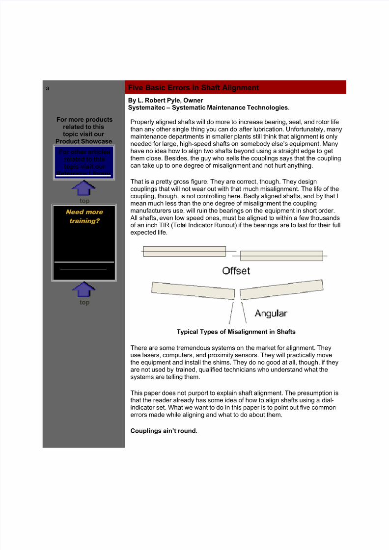
#ll shafts, even low speed ones, must be aligned to within a few thousandsof an inch !"$ %!otal "ndicator $unout& if the bearings are to last for their fulle'pected life.
!y"ical !y"es of isalignment in Shafts
!here are some tremendous systems on the market for alignment. !heyuse lasers, computers, and pro'imity sensors. !hey will practically movethe equipment and install the shims. !hey do no good at all, though, if theyare not used by trained, qualified technicians who understand what thesystems are telling them.
!his paper does not purport to e'plain shaft alignment. !he presumption isthat the reader already has some idea of how to align shafts using a dial-indicator set. (hat we want to do in this paper is to point out five commonerrors made while aligning and what to do about them.
(o$"lings ain)t ro$n#.

7/27/2019 Five basic errors in shaft alignment.doc
http://slidepdf.com/reader/full/five-basic-errors-in-shaft-alignmentdoc 2/6
)uppose we have two shafts that are perfectly aligned but one has acoupling improperly mounted on a shaft so that there is some error incolinearity of the a'es. #s we approach the maching the error is only in thehori*ontal direction. +et’s set up the dial indicator so that it reads theoutside of the coupling then rotate only the shaft on which the indicator ismounted, leaving the coupling still. (hen we get to position the dialindicator will be e'tended to, say, -. inches due to the error. !urning to
position will bring the dial indicator back to *ero. #t position / the indicator is compressed due the error and reads 0.. "f we believe that thecoupling is square on the shaft and the a'es are collinear we will believethat there is a !"$ or . inches in the hori*ontal direction. #cting on thatinformation will cause us to misalign the shafts by . inches 1introducing vibration and potential bearing damage.
2ow can we eliminate that error3 y rotating both shafts together. !heroundness of the coupling, the roughness of its surface, and the poormounting will be eliminated from the readings %actually, all of those thingswill cause compensating errors so that only the actual misalignment of thetwo shafts will be indicated by the dials.
# better way is to eliminate reading the coupling at all by using a target foryour indicator that is securely mounted on the shaft. !his will necessitaterotating both shafts but eliminates the need to break the coupling, even todo rim-face readings.
ove the %river
!his seems almost intuitive 1 at least if you have been in the field for any

7/27/2019 Five basic errors in shaft alignment.doc
http://slidepdf.com/reader/full/five-basic-errors-in-shaft-alignmentdoc 3/6
time. 4et, " repeatedly have had clients who ine'plicably believed it waseasier to move the driven machine. " will not argue that there is a time whenthe driven should be aligned to the driver. "n all of industry, there areundoubtedly situations where this is better. #s a general rule, though, it isbetter to move the driver that is not connected to your process than tomove the driven that is.
5or e'ample, suppose we are aligning a pump and motor. !he pump isconnected to the process by an inlet pipe and an outlet pipe. !here aresome applications where the piping is connected through fle'-6oints but "haven’t found very many of them. Most of the time, the pump is hard-pipedinto the system. " will make an assumption that you have corrected anypipe strain in the system. "f not, then do that before trying to align the pump.4ou are 6ust kidding yourself otherwise.
7nce the pump has been connected to the system, any attempt to movethe pump to align it to the motor will induce pipe strain8 whereas, movingthe motor strains nothing but the fle'tite on the electrical connection 1 and itwas made to be strained. "f you move the pump and introduce pipe strain,you will end up with a misaligned pump as soon as you start the system up.2ot fluid, cold fluid or 6ust the movement of the fluid will begin to fle' thepiping system which will, in turn, move your pump, which will in turn ruinthat careful alignment you 6ust accomplished.
!hrea#s #on)t increase Strength
#t one client’s plant " gave a four-hour class on shaft alignment. #t the endof the class, we went to the field to practice on a 9 2p pump. !his was apump that had been :aligned; by that crew the week before. !he plant hadbeen in service for about two years and the bearings had been failing on
this pump every si' months. "n the middle of the class, there had beensome sheepish looks and, when " questioned them, they admitted that theyhad never heard of angular misalignment and had only been correctingoffset since startup.
(ith information from the first pass of readings, the computer required amovement of the back end of the motor which was . to .9 morethan the holes in the motor mount would allow. #fter some cursing, the crewbegan to disassemble the coupling and pull all the mounting bolts. "stopped them and asked what they were planning. :(e have to take themotor to the shop and enlarge the holes in the feet,; was the answer.
!here are times when the two devices may be so misaligned that that kind
of action may be necessary. <eeding less than .9 inches is not that kindof misalignment. (hen you run across this situation, do this= Pull theoffending bolt, take it to the shop and turn or grind the threads off in thearea that is in contact with the motor foot. 4ou can grind all the threadsdown to the root diameter and not effect the strength in tension at all. 7n a9>? 1 bolt the 7@ at the threads is .AB inches. !he root is .99 inches.)o, you can pick up .9 inches of movement with no decrease instrength by grinding the threads.

7/27/2019 Five basic errors in shaft alignment.doc
http://slidepdf.com/reader/full/five-basic-errors-in-shaft-alignmentdoc 4/6
esides, " have seen many alignments where the computer moved theoffending foot right back after the second pass. Cnlarging the hole in thefoot would have been an e'treme waste of time.
* Planes are Better !han +
" have seen alignment techniques that suggest that the technician align firstthe hori*ontal then the vertical. " disagree with that. " believe you should bemaking complete passes 1 all four positions, and calculating both your
vertical and hori*ontal correction at the same time. 2ere’s why=
"f the alignment is far out, it is better to correct both planes %hori*ontal andvertical& at the same time. 7therwise the requirement for positioning theindicators becomes too precise. Crror will be introduced and you will end upbouncing around the solution for any one plane.
)uppose you are nearly perfect in the vertical direction yet still grosslymisaligned in the hori*ontal as illustrated in the above figure. "f you do notplace your dial indicator e'actly vertically, part of the gross hori*ontalmisalignment will be read as vertical misalignment. !his will cause you tobounce around the solutions with each pass.
"t is better to remove the error from both planes together so that thissituation does not arise. (ith the availability of computers, laser systems,etc. there is not reason not correct both planes simultaneously.
Reverse n#icator -ors
Most e'perienced mechanics and engineers will shrug at that statement. 7f course, reverse indicator systems work. My e'perience as a teacher and as
7/27/2019 Five basic errors in shaft alignment.doc
http://slidepdf.com/reader/full/five-basic-errors-in-shaft-alignmentdoc 5/6
a consultant belies that complacency. " have found e'perienced crews whoknew nothing but rim-face techniques or who knew of $" but did not believeit worked. " had one very e'perienced technician tell me that $" only workedon very large shafts.
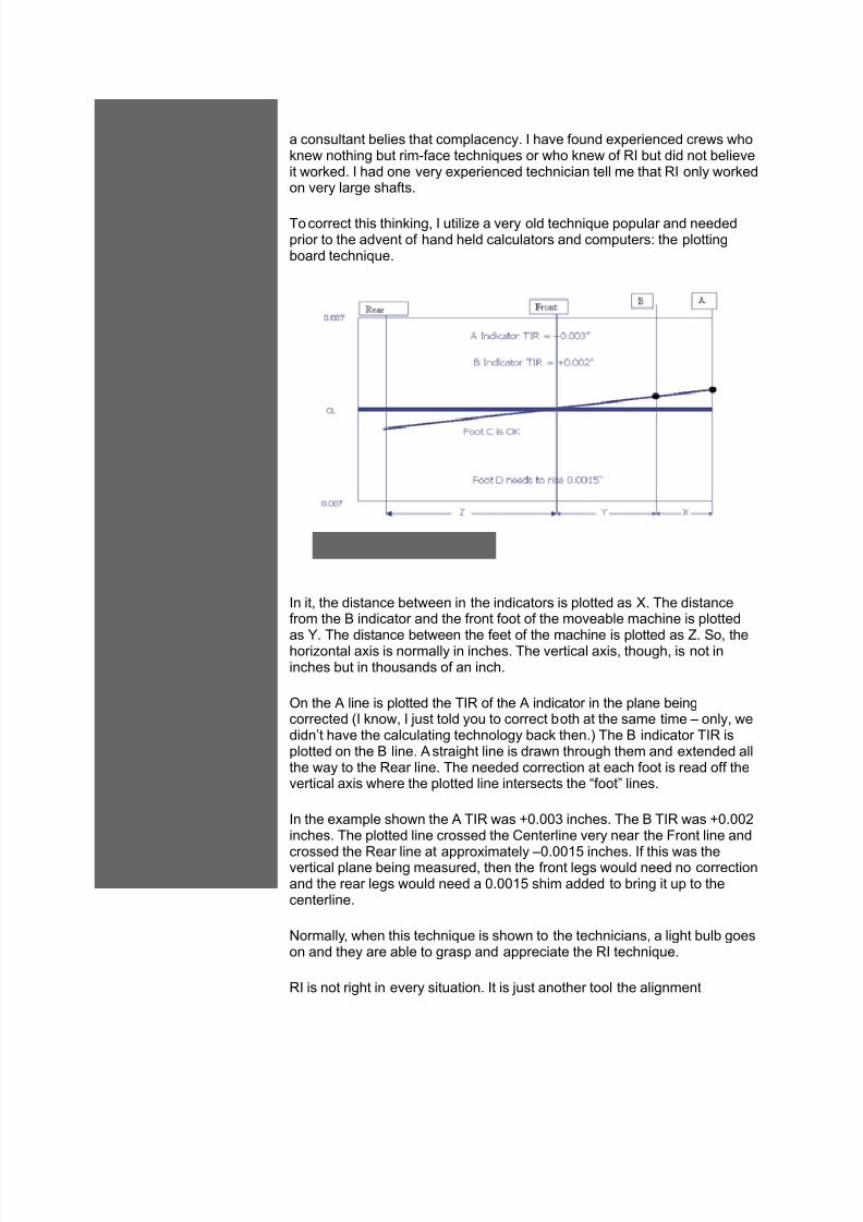
!o correct this thinking, " utili*e a very old technique popular and neededprior to the advent of hand held calculators and computers= the plottingboard technique.
"n it, the distance between in the indicators is plotted as D. !he distancefrom the indicator and the front foot of the moveable machine is plotted
as 4. !he distance between the feet of the machine is plotted as E. )o, thehori*ontal a'is is normally in inches. !he vertical a'is, though, is not ininches but in thousands of an inch.
7n the # line is plotted the !"$ of the # indicator in the plane beingcorrected %" know, " 6ust told you to correct both at the same time 1 only, wedidn’t have the calculating technology back then.& !he indicator !"$ isplotted on the line. # straight line is drawn through them and e'tended allthe way to the $ear line. !he needed correction at each foot is read off thevertical a'is where the plotted line intersects the :foot; lines.
"n the e'ample shown the # !"$ was 0./ inches. !he !"$ was 0.inches. !he plotted line crossed the Fenterline very near the 5ront line and
crossed the $ear line at appro'imately 1.9 inches. "f this was thevertical plane being measured, then the front legs would need no correctionand the rear legs would need a .9 shim added to bring it up to thecenterline.
<ormally, when this technique is shown to the technicians, a light bulb goeson and they are able to grasp and appreciate the $" technique.
$" is not right in every situation. "t is 6ust another tool the alignment

7/27/2019 Five basic errors in shaft alignment.doc
http://slidepdf.com/reader/full/five-basic-errors-in-shaft-alignmentdoc 6/6
technician has for getting the 6ob done. "ts biggest advantage is ease of setup and a balanced rotor compared to $im-5ace %$5&. !he $" set up isbalanced and will not rotate unless made to. !he $5 is unbalanced and willrotate to the bottom position unless held in place.
!hese five errors, although simple and basic to the e'perienced mechanic,are ones that " have found many clients making 1 and making without evenreali*ing there was an error involved. !eaching these things to anine'perienced crew or to your new craftspeople will improve youralignments and make them more time efficient.
to"
+. $obert Pyle)ystemaitec 5irst <orth #merican )erial $ights only
99 $olling 2ills Fopyright +. $. Pyle(ichita, G) AH/9 /A-H-AB//
"f you have any comments about the article you have 6ust read and you would like to share them with us at!(" Press, please feel free to email $s by clicking on the email button below.
($rrent ss$e Archives E/mail 0s
1 (o"yright *22* !- Press, nc.
Phone3 4+*.*5*.2675 / Fa83 4+*.*5*.5964 / E/ail3 info:maintenancereso$rces.com
A##ress3 +*2 So$th 6th Street / !erre ;a$te, < =6426
![Standard optical Sendix Base KIS50 / KIH50 (shaft / hollow shaft) … 2 kuebler.com SW7 [0,28] 50,2 80,31 0,16 0, 2 8 7 m8 4 M4 R 301,18 0,16 rit Kbler mbH, subect to errors and changes.](https://static.fdocuments.net/doc/165x107/611f702e359c6a200f08e0ee/standard-optical-sendix-base-kis50-kih50-shaft-hollow-shaft-2-sw7-028-502.jpg)