Fittings & Technical Guide - Fastclamp – Tubular Fittings · FastClamp fittings are suitable for...
20
Fittings & Technical Guide
Transcript of Fittings & Technical Guide - Fastclamp – Tubular Fittings · FastClamp fittings are suitable for...

Fittings & Technical Guide

02 ©2012 Access Technologies Limited. All Rights Reserved.
FastClamp is a range of fittings manufactured from Malleable Iron to BS EN 1562 or Ductile Iron (where noted in the fittings description) to BS EN 1563 . FastClamp fittings are used to construct lightweight tubular steel structures and are manufactured to suit five different tube sizes.
FastClamp fittings require no welding, drilling or special tools, simply use a hexagon key to tighten the special setscrews that embed into the tube. FastClamp fittings will support an axial load of up to 900 kg when tightened to a torque of 39Nm.
FINISHES AVAILABLEFastClamp castings are Hot dip Galvanised to BS EN ISO 1461 as standard. FastClamp fittings can also be supplied in a powder coated finish to RAL standard colours, subject to quantity and availability from the coaters.
FastClamp fittings are suitable for use with steel tubes to BS EN 10255 with a minimum wall thickness of 3.2mm, however please note that internal fitting types: C01, C06, C65, DDA-02 & DDA-06 are only designed for use with 3.2mm thick tube.Product codes are constructed as follows:
C = FastClampNo. = FastClamp typeG = GalvanisedP = PlasticS = Stainless SteelNo. = Tube size Example: C00G20 is a FastClamp, type 00, galvanised and suitable for 26.9mm diameter tube.
FASTCLAMP SELECTION
60.3mm50
40 48.3mm
42.4mm32
33.7mm25
26.9mm20
Fitting Tube size øNominal bore of tubeMetric Imperial
20 26.9mm 20 3/4”
25 33.7mm 25 1”
32 42.4mm 32 1 1/4”
40 48.3mm 40 1 1/2”
50 60.3mm 50 2”
Important Note: The Tube Size Ø should be the first consideration as this is the primary structural component for any FastClamp structure. The application guidelines on the next page will help the design of Racking, General Structures and Handrail.
The safe clamping system for circular hollow section tubeAccess Technologies Limited was established in 1995 to manufacture access equipment for the Construction Industry. The FastClamp brand followed as a natural progression four years later and has since grown to become one of the premier ranges of slip on tubular fittings available today.
Introduction

03 ©2012 Access Technologies Limited. All Rights Reserved.
Application Guidelines
Horizontal tubes load capacityUniformally distributed load in kg using two horizontal tubes
Vertical strut load capacityVertical load in kg per strut
Table 1
Table 2
Racking and general structures
Tube Ø
Tube Ø
Guardrail
360 N/m 814 1369 1595 1828 2584 3052
740 N/m 396 666 776 889 1257 2229
1500 N/m 195 329 383 439 620 1100
900 mm high
360 N/m 732 1232 1435 1645 2326 2930
740 N/m 356 599 698 800 1131 2006
1500 N/m 176 296 345 395 558 990
1000 mm high
360 N/m 666 1120 1305 1496 2114 2778
740 N/m 324 545 635 728 1028 1824
1500 N/m 160 269 313 359 507 900
1100 mm high
Maximum Upright Centres (mm)
Tube Ø 33.7 x 3.2mm 42.4 x 3.2mm 42.4 x 4.0mm 48.3 x 3.2mm 48.3 x 4.0mm 48.3 x 5.0mm
Design Load
Grade: BS EN 10255 (ISO 65)Rails need only be 3.2mm thick and the same diameter as the Upright.
Racking and general structures can be constructed using FastClamp fittings. Care must be taken to ensure that the tube size selected is adequate for the loads anticipated. To help with the selection of the correct tube, table 1 provides the uniformly distributed loads that can be supported between upright posts, assuming that the load is supported by two tubes. These loads are calculated based on the maximum bending movement for the tube.
Table 2 provides the load capacity for single upright posts with various unsupported lengths. These loads are based on the compression strength and buckling loads of the circular hollow section (CHS) tube.
NB. When designing structures care must be taken to ensure that the load on any one grub screw does not exceed 900kg.
For further help in using FastClamp please contact our sales office.
Guardrail is the most common form of structure that is built with FastClamp fittings and requires careful consideration to meet required design loadings. Design loads are usually specified, however if unsure BS 6399 and BS 6180 are good reference documents.
The loading capacity of any guardrail structure is determined principally by the diameter, thickness and frequency of its Uprights.The table below contains our recommendations to safely meet the stated design loads based on the maximum permissible bending moment of the Upright tube.
Span(m)
26.9mmx 2.6
33.7mmx 3.2
42.4mmx 3.2
48.3mmx 3.2
60.3mmx 3.6
0.5 540 1060 1750 2380 4000
0.6 435 850 1407 1870 3250
0.7 375 730 1207 1595 2760
0.8 330 645 1063 1385 2420
0.9 295 579 946 1230 2160
1.0 265 525 850 1110 1950
1.1 240 478 770 1013 1775
1.2 219 438 705 930 1625
1.3 202 403 651 858 1497
1.4 187 373 604 796 1387
1.5 175 347 564 741 1290
1.6 - 325 529 693 1205
1.7 - 306 499 650 1129
1.8 - 290 472 613 1061
1.9 - 277 448 581 999
2.0 - 268 427 553 987
2.1 - - 408 528 944
2.2 - - 391 505 855
2.3 - - 376 485 818
2.4 - - 362 467 785
2.5 - - 349 450 755
2.6 - - - 434 728
2.7 - - - 419 703
2.8 - - - 405 680
2.9 - - - - 659
3.0 - - - - 639
3.1 - - - - 620
3.2 - - - - 603
3.3 - - - - 588
3.4 - - - - 575
3.5 - - - - 564
Length(m)
26.9mmx 2.6
33.7mmx 3.2
42.4mmx 3.2
48.3mmx 3.2
60.3mmx 3.6
0.3 1720 2950 4038 4783 7044
0.4 1435 2617 3703 4446 6661
0.5 1150 2284 3368 4109 6278
0.6 910 1951 3033 3772 5895
0.7 725 1618 2690 3435 5512
0.8 590 1348 2363 3098 5129
0.9 480 1128 2028 2761 4746
1.0 - 948 1752 24244363
1.1 - 798 1524 2134 3980
1.2 - - 1340 1884 3597
1.3 - - 1188 1668 3253
1.4 - - 1066 1484 2951
1.5 - - - 1328 2681
1.6 - - - - 2441
1.7 - - - - 2226
1.8 - - - - 2032
1.9 - - - - 1857
2.0 - - - - 1697
Grade: BS EN 10255 (ISO 65)
Grade: BS EN 10255 (ISO 65)
Table 3
04
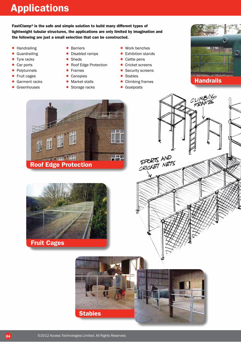
Applications
Handrails
Roof Edge Protection
Fruit Cages
Stables
FastClamp®is the safe and simple solution to build many different types of lightweight tubular structures, the applications are only limited by imagination and the following are just a small selection that can be constructed.
● Handrailing● Guardrailing● Tyre racks● Car ports● Polytunnels● Fruit cages● Garment racks● Greenhouses
● Barriers● Disabled ramps● Sheds● Roof Edge Protection● Frames● Canopies● Market stalls● Storage racks
● Work benches● Exhibition stands● Cattle pens● Cricket screens● Security screens● Stables● Climbing frames● Goalposts
©2012 Access Technologies Limited. All Rights Reserved.

05
Handrails
Guardrailing
Storage Racks
Boat Racks
Trolley Parks
©2012 Access Technologies Limited. All Rights Reserved.
06
Products
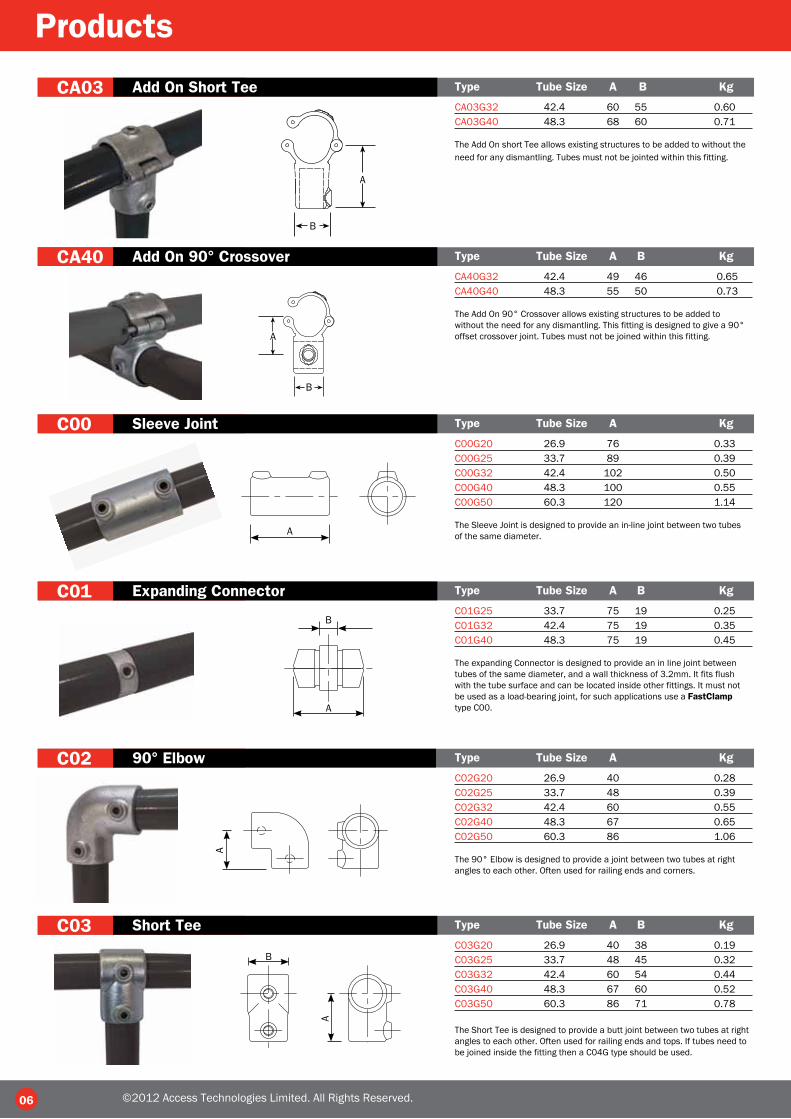
CA03 Add On Short Tee Type Tube Size A B Kg
CA03G32 42.4 60 55 0.60CA03G40 48.3 68 60 0.71
The Add On short Tee allows existing structures to be added to without the need for any dismantling. Tubes must not be jointed within this fitting.
CA40 Add On 90° Crossover Type Tube Size A B Kg
CA40G32 42.4 49 46 0.65CA40G40 48.3 55 50 0.73
The Add On 90° Crossover allows existing structures to be added towithout the need for any dismantling. This fitting is designed to give a 90°offset crossover joint. Tubes must not be joined within this fitting.
C00 Sleeve Joint Type Tube Size A Kg
C00G20 26.9 76 0.33C00G25 33.7 89 0.39C00G32 42.4 102 0.50C00G40 48.3 100 0.55C00G50 60.3 120 1.14
The Sleeve Joint is designed to provide an in-line joint between two tubesof the same diameter.
C01 Expanding Connector Type Tube Size A B Kg
C01G25 33.7 75 19 0.25C01G32 42.4 75 19 0.35C01G40 48.3 75 19 0.45
The expanding Connector is designed to provide an in line joint betweentubes of the same diameter, and a wall thickness of 3.2mm. It fits flushwith the tube surface and can be located inside other fittings. It must notbe used as a load-bearing joint, for such applications use a FastClamptype C00.
C02 90° Elbow Type Tube Size A Kg
C02G20 26.9 40 0.28C02G25 33.7 48 0.39C02G32 42.4 60 0.55C02G40 48.3 67 0.65C02G50 60.3 86 1.06
The 90° Elbow is designed to provide a joint between two tubes at rightangles to each other. Often used for railing ends and corners.
C03 Short Tee Type Tube Size A B Kg
C03G20 26.9 40 38 0.19C03G25 33.7 48 45 0.32C03G32 42.4 60 54 0.44C03G40 48.3 67 60 0.52C03G50 60.3 86 71 0.78
The Short Tee is designed to provide a butt joint between two tubes at rightangles to each other. Often used for railing ends and tops. If tubes need tobe joined inside the fitting then a C04G type should be used.
A
A
A
A
B
©2012 Access Technologies Limited. All Rights Reserved.
B
A
B
A
B

07
C04 Long Tee Type Tube Size A B Kg
C04G20 26.9 40 80 0.35C04G25 33.7 48 96 0.60C04G32 42.4 60 122 0.75C04G40 48.3 67 134 0.91C04G50 60.3 86 172 1.47
The Long Tee is designed to provide a butt joint between two tubes at rightangles to each other. Often used for railing ends and tops. It allows the through tube to be joined inside the fitting. An alternative is the C03G type fitting.
C05 Variable Elbow Type Tube Size A B C D Kg
C05G25 33.7 65 60 13 50 0.41C05G32 42.4 80 66 16 55 0.68C05G40 48.3 95 75 17 55 0.89
The Variable Elbow is designed to make joints at an angle of between 15° and 60°.
C06 Internal T Joint Type Tube Size A B C Kg
C06G25 33.7 23 33 34 0.39C06G32 42.4 29 42 40 0.58C06G40 48.3 31 48 42 0.66
The Internal T joint is designed to provide an angled joint between a tube and a FastClamp fitting when used in conjunction with C02G and C03G type fittings. Often used for railing tops and midrails to accommodate a slope as offset railing.
C07 45° Tee Type Tube Size A Kg
C07G25 33.7 45 0.49C07G32 42.4 54 0.69C07G40 48.3 60 0.91
The 45° Tee is used as a bracing and strut component for strengthening structures.
C10G Swivel Base Type Tube Size A B C D E Kg
C10G N/A 50 40 50 81 111 0.35
The Swivel Base is designed to provide a base fixing. It is usually used inconjunction with a C36G type fitting to make a C46G type base swivelcombination. This fitting does not provide sufficient rigidity to be used asa railing base without other means of support.
C11 Wall Flange Type Tube Size A B C D Ø Kg
C11G20 26.9 86 42 57 4 9 0.32C11G25 33.7 89 45 64 6 9 0.41C11G32 42.4 102 50 76 6 9 0.50C11G40 48.3 114 57 89 6 9 0.65C11G50 60.3 127 64 95 6 9 1.10
The Wall Flange is designed to provide a positional wall or base fixing.It is not recommended to use this fitting as a structural railing base.
B
A
DE
BA
C
A
10mm ø hole2 no 10mm ø
holes
©2012 Access Technologies Limited. All Rights Reserved.
B
A
DC
a
b
c
D
BC
A
45°

08
Products
C12 Railing Base Flange Type Tube Size A B C D E Ø Kg
C12G20 26.9 76 65 8 76 114 11 0.65C12G25 33.7 89 76 9 89 128 14 0.96C12G32 42.4 89 80 10 102 140 14 1.07C12G40 48.3 89 89 10 114 152 14 1.24C12G50 60.3 128 88 9 127 165 18 1.80
The Railing Base is designed to provide a base for railings and other structures. It is recommended that this fitting be used in accordance with FastClamp maximum post centre dimensions, see table 3 on our Technical Page.
C13 Railing Vertical Side Support Type Tube Size A B C D E Ø Kg
C13G25 33.7 45 96 67 25 104 14 0.91C13G32 42.4 50 109 78 30 114 14 1.20C13G40 48.3 60 123 86 40 120 14 1.50
The Railing Vertical Side Support is designed to provide a base for railings and other structures that need a side mounted fixing. It is recommended that this fitting be used in accordance with FastClamp maximum post centre dimensions, see table 3 on our Technical Page.
C14 Railing Horizontal Side Support Type Tube Size A B C Ø Kg
C14G25 33.7 90 30 12 18 0.92C14G32 42.4 90 35 12 18 1.41C14G40 48.3 90 41 15 18 1.53
The Railing Horizontal Side Support is designed to provide a base forrailings and other structures that need a side mounted fixing. It isrecommended that this fitting be used in accordance with FastClampmaximum post centre dimensions, see table 3 on our Technical Page.
C15 Side Palm Fixing Type Tube Size A B C D E Ø Kg
C15G25 33.7 76 89 71 63 97 11 0.65C15G32 42.4 84 98 82 72 108 11 0.82C15G40 48.3 92 104 86 78 112 11 0.88
The Side Support is designed to provide a base for railings and otherstructures that need a side mounted fixing. It is recommended that thisfitting be used in accordance with FastClamp maximum post centredimensions, see table 3 on our Technical Page.
C16 Handrail Bracket Type Tube Size A B C D Ø Kg
C16G20 26.9 44 57 55 78 9 0.45C16G25 33.7 44 63 57 82 11 0.49C16G32 42.4 44 76 63 102 11 0.60C16G40 48.3 48 85 67 108 11 0.63
The Handrail Bracket is designed to secure handrail tube to a wall. It canalso be used on top of walls as a fixing for a low rail.
C17 Ground Support Type Tube Size A B C D Kg
C17G25 33.7 60 140 130 4.5 1.42C17G32 42.4 60 140 130 4.5 1.42C17G40 48.3 60 140 130 4.5 1.42
The Ground Socket is designed to provide a base that can be cast into theground to support a post. The post is removable. It is recommended thatthis fitting be used in accordance with FastClamp maximum post centredimensions, see table 3 on our Technical Page.
E65
BCA
ø holes
ABC
D
E
ø holes
65A 150
100
BC
ø holes
C
BD
ø holes
A
©2012 Access Technologies Limited. All Rights Reserved.
D
AB
C
D
E
A
B
D
C

09
C18 Base Flange with Integrated Toeboard Type Tube Size A B C D E Ø Kg
C18G32 42.4 45 90 58 30 100 18 2.00C18G40 48.3 45 90 58 30 100 18 2.12
The Base Flange with Integrated Toeboard is ideal for guardrailing andbalustrading applications where the addition of a toeboard is required.The side plates have slotted holes to allow for a degree of sidewaysmovement for ease of installation. It is recommended that this fitting beused in accordance with FastClamp maximum post centre dimensions,see table 3 on our Technical Page.
C20 3 Way 90° Elbow Type Tube Size A Kg
C20G20 26.9 40 0.37C20G25 33.7 48 0.53C20G32 42.4 60 0.80C20G40 48.3 67 1.05C20G50 60.3 84 1.82
The 3 way 90° Elbow is designed to provide a neat corner for the upper rail of guardrail or frames.
C21 Corner c/w Through Tube Type Tube Size A B Kg
C21G20 26.9 40 38 0.26C21G25 33.7 48 45 0.43C21G32 42.4 60 54 0.58C21G40 48.3 67 60 0.69C21G50 60.3 86 71 1.70
The Corner Complete with through tube is designed to provide a 90°corner for the intermediate rail of guardrail or frames.
C22 Two Socket Cross Type Tube Size A B Kg
C22G20 26.9 40 80 0.36C22G25 33.7 48 95 0.43C22G32 42.4 60 120 0.62C22G40 48.3 67 134 0.71C22G50 60.3 86 172 1.50
The Two Socket Cross fitting provides the midrail joint for handrail andother structures. It is recommended that the handrail post is continuousthrough the fitting.
C23 Side Outlet Tee 45° Type Tube Size A B Kg
C23G20 26.9 40 38 0.42C23G25 33.7 48 45 0.49C23G32 42.4 60 54 0.94C23G40 48.3 66 60 0.87C23G50 60.3 86 71 1.67
The Side Outlet Tee fitting provides a three way midrail joint for handrailand other structures. It is recommended that the handrail post iscontinuous through the fitting.
C24 4 Way Cross + Central Tube Type Tube Size A B Kg
C24G20 26.9 41 59 0.60C24G25 33.7 48 65 0.84C24G32 42.4 60 80 1.21C24G40 48.3 67 85 1.19C24G50 60.3 86 90 2.50
The 4 Way Cross fitting provides a four way midrail joint for handrail and other structures. It is recommended that the handrail post is continuous through the fitting. This fitting may also be used for the top rail with the centre post capped with a C65 Plastic Stop End.
A
A
B
B
A
A
A
A
B
©2012 Access Technologies Limited. All Rights Reserved.
AB
CD
E
A
A
A
B
A
10
Products
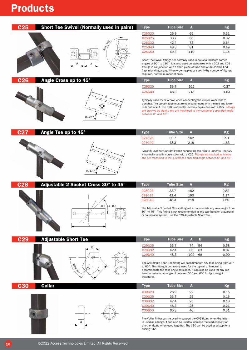
C25 Short Tee Swivel (Normally used in pairs) Type Tube Size A Kg
C25G20 26.9 65 0.31C25G25 33.7 66 0.32C25G32 42.4 73 0.54C25G40 48.3 81 0.49C25G50 60.3 110 1.14
Short Tee Swivel fittings are normally used in pairs to facilitate corner angles of 90° to 180°. It is also used on staircases with a C02 and C03 fittings in conjunction with a short piece of tube and a C65 Plastic End Cap in landing areas. When ordering please specify the number of fittings required, not the number of pairs.
C26 Angle Cross up to 45° Type Tube Size A Kg
C26G25 33.7 162 0.87
C26G40 48.3 218 1.63
Typically used for Guardrail when connecting the mid or lower rails to uprights. The upright tube must remain continuous with the mid and lower rails cut to suit. The C26 is normally used in conjunction with a C27. Fittings are stocked as blanks and are machined to the customer’s specified angle between 0° and 45°.
C27 Angle Tee up to 45° Type Tube Size A Kg
C27G25 33.7 162 0.91C27G40 48.3 218 1.63
Typically used for Guardrail when connecting top rails to uprights. The C27 is normally used in conjunction with a C26. Fittings are stocked as blanks and are machined to the customer’s specified angle between 0° and 45°.
C28 Adjustable 2 Socket Cross 30° to 45° Type Tube Size A Kg
C28G25 33.7 162 0.82C28G32 42.4 190 1.17C28G40 48.3 218 1.50
The Adjustable 2 Socket Cross fitting will accommodate any rake angle from 30° to 45°. This fitting is not recommended as the top fitting on a guardrail or balustrade system, use the C29 Adjustable Short Tee.
C29 Adjustable Short Tee Type Tube Size A B Kg
C29G25 33.7 74 54 0.58C29G32 42.4 85 63 0.87C29G40 48.3 102 68 0.90
The Adjustable Short Tee fitting will accommodate any rake angle from 30° to 60°. This fitting is commonly used for the top rail of handrail to accommodate the rake angle on slopes. It can also be used for any Tee Joint to make at an angle of between 30° and 60° for light weight structures.
C30 Collar Type Tube Size A Kg
C30G20 26.9 22 0.15C30G25 33.7 25 0.15C30G32 42.4 25 0.18C30G40 48.3 25 0.21C30G50 60.3 40 0.31
The Collar fitting can be used to support the C03 fitting when the latter is used as a hinge. It can also be used to increase the load capacity of another fitting when used together. The C30 can be used as a stop for a sliding tube.
A A
30º to 45º
30º to 60º
A
B
A
A
©2012 Access Technologies Limited. All Rights Reserved.
0/45°
A
0/45°
A

11
C31 Gate Eye Type Tube Size A B C Kg
C31G20 26.9 25 30 15 0.21C31G25 33.7 25 33 15 0.23C31G32 42.4 25 38 15 0.25C31G40 48.3 25 41 15 0.29
This fitting is designed as a gate eye for light weight gates. If a heavy gate is being used we recommend that C03 and C30 type fittings are used to support the gate.
C33 Hook Type Tube Size A B C D Kg
C33G20 26.9 32 25 10 25 0.17C33G25 33.7 34 25 13 21 0.25C33G32 42.4 39 25 13 25 0.25C33G40 48.3 41 25 13 25 0.30
The fitting is designed to provide an attachment for chain.
C34 Fixing Pad Type Tube Size A B C Ø Kg
C34G25 26.9 45 25 5 6 0.18C34G32 33.7 53 40 5 11 0.34C34G40 42.4 56 40 5 11 0.37
The fitting is designed to provide an attachment for flat sheets or board. It may also be used as a gate stop. An alternative fitting for the attachment of boards is the C35 type.
C32 Gate Hinge Type Tube Size A B C D Kg
C32G20 26.9 30 25 13 38 0.24C32G25 33.7 33 25 13 38 0.27C32G32 42.4 38 25 13 38 0.30C32G40 48.3 41 25 13 38 0.33
This fitting is designed as a gate hinge for light weight gates. If a heavy gate is being used we recommend that C03 and C30 type fittings are used to support the gate.
A CA
B
C
B
©2012 Access Technologies Limited. All Rights Reserved.
A
C
D
B
A
B
C
D
C35 Male Swivel Type Tube Size A B C Ø Kg
C35G20 26.9 32 38 8 10 0.18C35G25 33.7 32 42 8 10 0.20C35G32 42.4 32 47 8 10 0.21C35G40 48.3 32 50 8 10 0.24C35G50 60.3 48 60 8 10 0.53
The Male Swivel can be used on its own for use with a shakle and chain or with the C36 female swivel to mount rails at any angle for slopes. It can also be used for attaching flat sheets or boards to a structure and is available assembled with the C36 fittings as a C45 single swivel combination.
C36F Female Swivel Type Tube Size A B C D Kg
C36G20F 26.9 39 35 53 10 0.28C36G25F 33.7 41 35 60 10 0.35C36G32F 42.4 44 35 63 10 0.41C36G40F 48.3 50 35 70 10 0.46C36G50F 60.3 70 40 95 10 0.88
The Female Swivel is designed as part of the swivel combination group of fittings. It can be used with the C10, C35, C37, C38 or C39 male swivel fittings.
C
B
38ø
A
ø
AB
C
D
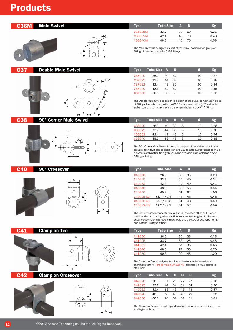
C37 Double Male Swivel Type Tube Size A B Ø Kg
C37G20 26.9 40 32 10 0.27C37G25 33.7 44 32 10 0.28C37G32 42.4 49 32 10 0.34C37G40 48.3 52 32 10 0.35C37G50 60.3 63 50 10 0.63
The Double Male Swivel is designed as part of the swivel combination group of fittings. It can be used with two C36 female swivel fittings. The double swivel combination is also available assembled as a type C47 fitting.
C38 90° Corner Male Swivel Type Tube Size A B C Ø Kg
C38G20 26.9 40 39 8 10 0.28C38G25 33.7 44 38 8 10 0.30C38G32 42.4 49 48 8 10 0.34C38G40 48.3 53 48 8 10 0.38
The 90° Corner Male Swivel is designed as part of the swivel combination group of fittings. It can be used with two C36 female swivel fittings to make a corner combination fitting which is also available assembled as a type C48 type fitting.
C40 90° Crossover Type Tube Size A B Kg
C40G20 26.9 36 35 0.20C40G25 33.7 40 40 0.34C40G32 42.4 49 49 0.41C40G40 48.3 55 55 0.54C40G50 60.3 61 64 1.06C40G25-32 33.7 / 42.4 45 45 0.46C40G25-40 33.7 / 48.3 51 48 0.50C40G32-40 42.2 / 48.3 51 52 0.59
The 90° Crossover connects two rails at 90° to each other and is often used for the handrailing when continuous standard lengths of tube are used. Please note that tube joints should use the C00 or C01 type fitting, and not the C40 type fitting.
C41 Clamp on Tee Type Tube Size A B Kg
C41G20 26.9 50 25 0.35C41G25 33.7 53 25 0.45C41G32 42.4 67 35 0.65C41G40 48.3 77 35 0.70C41G50 60.3 90 45 1.20
The Clamp on Tee is designed to allow a new tube to be joined to an existing structure. Torque maximum 15N\M. This uses a M10 stainless steel bolt.
C42 Clamp on Crossover Type Tube Size A B C D Kg
C42G20 26.9 37 28 27 27 0.18C42G25 33.7 44 34 34 34 0.30C42G32 42.4 53 43 43 43 0.47C42G40 48.3 58 49 49 49 0.65C42G50 60.3 70 62 61 61 0.81
The Clamp on Crossover is designed to allow a new tube to be joined to an existing structure.
12
Products
C36M Male Swivel Type Tube Size A B Kg
C36G25M 33.7 30 60 0.36C36G32M 42.4 40 70 0.48C36G40M 48.3 45 75 0.58
The Male Swivel is designed as part of the swivel combination group of fittings. It can be used with C36F fittings.
10ø
38ø
A A
B
A
A 10ø
C
B
B
38ø
AB
A
A
A
C
B
D
A
B
©2012 Access Technologies Limited. All Rights Reserved.

C43 Combination Socket Type Tube Size A B C Kg
C43G20 26.9 31 35 40 0.30C43G25 33.7 42 40 48 0.57C43G32 42.4 54 50 60 0.79C43G40 48.3 60 56 67 0.96C43G50 60.3 72 68 86 1.65
The Combination Socket is designed for racking and similar systems to allow a crossover to be combined with a cross tie.
13
C45 Single Swivel Combination Type Tube Size Kg
C45G20 26.9 0.48C45G25 33.7 0.60C45G32 42.4 0.71C45G40 48.3 0.86C45G50 60.3 1.47
The Single Swivel Combination is designed to provide and angled tee between two tubes. It can be used to construct sloping handrail and for providing bracing struts to structures.
C46 Base Swivel Combination Type Tube Size Kg
C46G20 26.9 0.64C46G25 33.7 0.77C46G32 42.4 0.94C46G40 48.3 0.98C46G50 60.3 1.29
The Base Swivel Combination is designed to provide an angled wall or floor mounting. This fitting should not be used as a railing base without suitable support.
C47 Double Swivel Combination Type Tube Size Kg
C47G20 26.9 0.90C47G25 33.7 1.06C47G32 42.4 1.25C47G40 48.3 1.45C47G50 60.3 2.50
The Double Swivel Combination is designed to provide an in line angled joint as a post, this is suitable for the mid rail of a sloping handrail or to provide bracing to a structure.
170º
170º
170º
170º
CB
A
©2012 Access Technologies Limited. All Rights Reserved.
C48 90° Corner Swivel Combination Type Tube Size Kg
C48G20 26.9 0.90C48G25 33.7 1.06C48G32 42.4 1.29C48G40 48.3 1.50
The 90° Corner Swivel Combination is designed to provide an angled joint at a post, this is suitable for the mid rail of sloping handrail or to provide bracing to a structure.
C50 Slope Elbow 0° to 11° Type Tube Size A Kg
C50G32 42.4 60 0.87C50G40 48.3 67 1.02
The Slope Elbow is designed to provide an elbow for use on ramps. The variable angle allows the fitting to accommodate slopes up to 11°.
A90̊ ±11̊

C52 Long Slope Tee 0° to 11° Type Tube Size A B Kg
C52G32 42.2 144 60 1.02C52G40 48.3 158 67 1.10
The Slope Long Tee is designed to provide a T joint between two tubes for use on ramps. The variable angle allows the fitting to accommodate slopes up to 11°.
C53 Slope Base 0° to 11° Type Tube Size A B C D E Ø Kg
C53G32 42.2 91 140 79 102 10 14 0.90C53G40 48.3 96 152 80 114 10 14 1.40
The Slope Base is designed to provide a base for use on ramps. The variable angle allows the fitting to accommodate slopes up to 11°.
C55 27½° Ridge Fitting Type Tube Size A B Kg
C55G40 48.3 67 89 0.96
A four way socket fitting used to construct the ridge of a roof structure.
C56 27½° Eaves Fitting Type Tube Size A B C D Kg
C56G40 48.3 67 89 83 51 1.19
A four way socket fitting used to construct the eaves of a roof structure.
14
Products
C51 Short Slope Tee 0° to 11° Type Tube Size A B Kg
C51G32 42.4 68 60 0.62C51G40 48.3 72 68 0.76
The Slope Short Tee is designed to provide a T joint between two tubes for use on ramps. The variable angle allows the fitting to accommodate slopes up to 11°.B
A
A
B
DB
C
A27.5˚
B
A A
27.5˚
©2012 Access Technologies Limited. All Rights Reserved.
±11̊
±11̊
A
BD
C
E
O˚-11̊
C54 Slope 2 Socket Cross 0° to 11° Type Tube Size A B Kg
C54G32 42.4 144 72 0.93C54G40 48.3 158 79 1.00
The Slope 2 Socket Cross is designed to provide a joint for the midrail for use on ramps. The variable angle allows the fitting to accommodate slopes up to 11°.
AB
O˚-11̊

C60 Spare Screws Type Tube Size
C60S25 26.9 & 33.7C60S32/40 42.4, 48.3 & 60.3
Spare Screws come in two sizes, 1/4” ISO 228 for the 20 and 25nb range and 3/8” ISO 228 for the 32, 40 and 50 ranges.
15
C61 Allen Keys Type Tube Size
C61S25 26.9 & 33.7C61S32/40 42.4, 48.3 & 60.3
Allen keys are available in two sizes, the first is suitable for the 20 and 25nb fitting and the other for the 32, 40 and 50nb fittings.
C62R Ratchet Keys Type Tube Size
C62R ALL SIZES
The Ratchet driver and dual keys are available to speed assembly. The Ratchet driver will allow tightening to the correct torque.
C65P Plastic End Cap Type Tube Size Kg
C65P20 26.9 0.008C65P25 33.7 0.010C65P32 42.4 0.010C65P40 48.3 0.016C65P50 60.3 0.024
Plastic End Caps are available for finishing plain end tubes. Available in grey plastic they will fit medium and heavy gauge tube.
©2012 Access Technologies Limited. All Rights Reserved.
C58 Two Socket 11° to 30° Cross Type Tube Size A B Kg
C58G32 42.4 180 55 1.30C58G40 48.3 216 60 1.45
Similar to a type C26, it is used on Safety Railing with slopes between 11º-30º and fixes the mid rail to a vertical intermediate upright. Unlike the type C26 these components are ex stock and do not require machining.
A
11°–29°B
C57 Three Socket 11° to 30° Tee Type Tube Size A B Kg
C57G32 42.4 180 35 1.40C57G40 48.3 216 40 1.58
Similar to a type C27, it is used on Safety Railing with slopes between 11º-30º and fixes the top rail to a vertical intermediate upright. Unlike the type C27 these components are ex-stock and do not require machining.
11°–29°
A
B
C59 11°–30°Angle Base Flange Type Tube Size A B C D Ø Kg
C59G32 42.4 76 114 85 146 14 1.27C59G40 48.3 89 124 95 164 14 1.42
Similar to a type C53, it is used to set the upright at an angle between 11º–30º. This fitting should only be subjected to light loads which cannot be positioned at 90º to the applied load. For greater loads or other tube sizes a type C12 flange should be used with the upright bent to the required angle Ø indicates the diameter of the fixing hole.
A
B
C
D

16
Products
C69 Square Plastic End Cap Type Tube Size B C Kg
C69P40X40 40x40SHS 40 3.2 0.01C69P50X50 50X50SHS 50 3.2 0.01C69P70X70 70X70SHS 70 3.2 0.02
The Plastic End Caps are available for finishing plain end square tubes. Available in grey plastic they will fit medium and heavy tube gauges.
C67 Double Mesh Clip Type Tube Size A B C Kg
C67G20 26.9 27 26 58 0.09C67G25 33.7 30 26 61 0.12C67G32 42.4 33 26 64 0.13C67G40 48.3 38 26 68 0.13C67G50 60.3 44 26 75 0.14
The Double Mesh Clip is designed to provide a fixing for standard mesh panels. It is recommended that the clips are spaced at a maximum of 450mm apart.
C68 Weather Cowl Type Tube Size A B H Kg
C68G20 33.7 140 25 125 0.25C68G25 42.4 150 25 150 0.30C68G40 48.3 166 25 150 0.35
The Weather Cowl is designed to cover the Railing base and provides a weather proof seal when used with a suitable flexible sealant.
C71 Crimp Elbow Type Tube Size A B C Kg
C71G25 33.7 26.0 38.0 34.0 0.47
Crimp Elbow provides a permanent 90° connection for 33.7mm diameter x 3.2mm thick tube, a crimping tool is necessary.
C70 Crimp Straight Type Tube Size AØ B Kg
C70G25 33.7 26.0 34.0 0.27
Straight Crimp Joints provide a permanent in-line connection for 33.7mm diameter x 3.2mm thick tube, a crimping tool is necessary.
øA
B
C
B
C
øA
B
©2012 Access Technologies Limited. All Rights Reserved.
C65G Metal End Cap Type Tube Size Kg
C65G20 26.9 0.05C65G25 33.7 0.10C65G32 42.4 0.12C65G40 48.3 0.17C65G50 60.3 0.29
This metal plug is hard to remove once it has been driven in. Note this metal insert can only be used in conjunction with tube with a wall thickness of 3.2mm. There is an alternative plastic version - C65P.
C66 Single Mesh Clip Type Tube Size A B C Kg
C66G20 26.9 27 26 58 0.06C66G25 33.7 30 26 61 0.07C66G32 42.4 33 26 64 0.08C66G40 48.3 38 26 68 0.09C66G50 60.3 44 26 75 0.09
The Single Mesh Clip is designed to provide a fixing for standard mesh panels. It is recommended that the clips are spaced at a maximum of 450mm apart.
A B
C
C C
B BA A
8.0 THEORETICAL WEIGHT OF SELF COLOUR BARE CASTING 0.46KG.MEAN THICKNESS 55 MICRONS MINIMUM 45 MICRONS
7.0 GALVANISING - IF REQUIRED TO BS EN ISO 1461: 6.0 DIMENSIONS INDICATED ARE AS CAST
YEAR OF MANUFACTURE (3MM HIGH) FOUNDRY MARK (3MM HIGH)
-0.00 MM UNLESS OTHERWISE STATED4.0 TOLERANCE ON ALL DIMENSIONS +1.00 MM
NTS
FastClampconsent of the owner. All rights reserved.or design depicted be disclosed without the prior writtencopied or reproduced in any way,nor may the informationimmediately on request. No part of the drawing may besupplied on loan in con�dence and must be returnedThis drawing is the property of Fastmat Ltd. It is
FIRST ISSUE
MODIFICATIONS DATEAPPROVREV NO
THIRD ANGLE PROJECTION DO NOT SCALE
DRAWING No.
FDT
APPRO
CHECK
SCALE
DATE
DRAWNA
Internet: www.fastclamp.com© 2007 Access Technologies Ltd. All rights reserved
Telephone: 01952 277779 Fax: 01952 277778Shifnal, Shropshire TF11 8DRAston StreetUnit 2, Springhill Industrial EstateAccess Technologies Ltd C71G25
C71G25
07 / 0707 / 07I.P.
C
B
A
17
The DDA Range
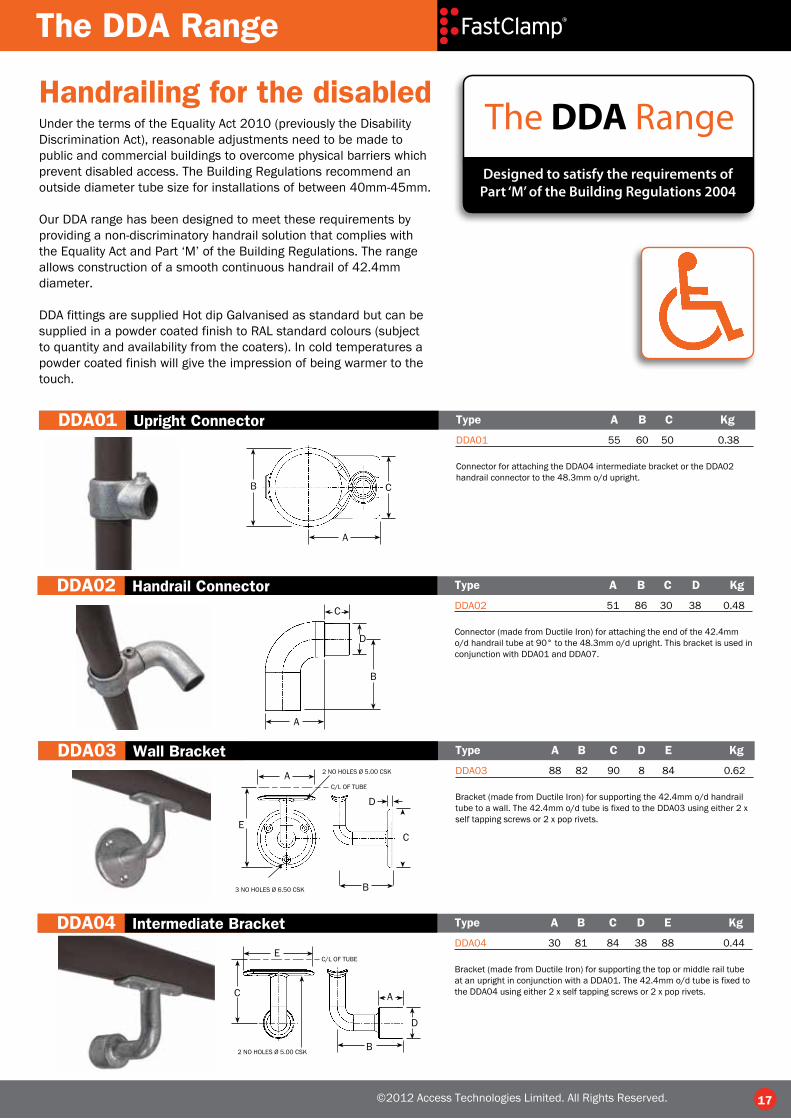
Handrailing for the disabledUnder the terms of the Equality Act 2010 (previously the Disability Discrimination Act), reasonable adjustments need to be made to public and commercial buildings to overcome physical barriers which prevent disabled access. The Building Regulations recommend an outside diameter tube size for installations of between 40mm-45mm. Our DDA range has been designed to meet these requirements by providing a non-discriminatory handrail solution that complies with the Equality Act and Part ‘M’ of the Building Regulations. The range allows construction of a smooth continuous handrail of 42.4mm diameter. DDA fittings are supplied Hot dip Galvanised as standard but can be supplied in a powder coated finish to RAL standard colours (subject to quantity and availability from the coaters). In cold temperatures a powder coated finish will give the impression of being warmer to the touch.
Designed to satisfy the requirements of Part ‘M’ of the Building Regulations 2004
The DDA Range
©2012 Access Technologies Limited. All Rights Reserved.
DDA01 Upright Connector Type A B C Kg
DDA01 55 60 50 0.38
Connector for attaching the DDA04 intermediate bracket or the DDA02 handrail connector to the 48.3mm o/d upright.
DDA02 Handrail Connector Type A B C D Kg
DDA02 51 86 30 38 0.48
Connector (made from Ductile Iron) for attaching the end of the 42.4mm o/d handrail tube at 90° to the 48.3mm o/d upright. This bracket is used in conjunction with DDA01 and DDA07.
DDA03 Wall Bracket Type A B C D E Kg
DDA03 88 82 90 8 84 0.62
Bracket (made from Ductile Iron) for supporting the 42.4mm o/d handrail tube to a wall. The 42.4mm o/d tube is fixed to the DDA03 using either 2 x self tapping screws or 2 x pop rivets.
C/L OF TUBE
3 NO HOLES Ø 6.50 CSK
2 NO HOLES Ø 5.00 CSK
DDA04 Intermediate Bracket Type A B C D E Kg
DDA04 30 81 84 38 88 0.44
Bracket (made from Ductile Iron) for supporting the top or middle rail tube at an upright in conjunction with a DDA01. The 42.4mm o/d tube is fixed to the DDA04 using either 2 x self tapping screws or 2 x pop rivets.
C/L OF TUBE
2 NO HOLES Ø 5.00 CSK
A
B C
C
A
B
D
A
B
C
D
E
A
B
C
D
E

The DDA Range
18 ©2012 Access Technologies Limited. All Rights Reserved.
DDA05 End Return Type A B C D E Kg
DDA05 90 82 8 86 46 0.64
Bracket (made from Ductile Iron) for terminating the 42.4mm o/d handrail tube back to a wall. This bracket is used in conjunction with a DDA07.
3 NO HOLES Ø 6.50 CSK
DDA06 90° Bend Type A B C Kg
DDA06 33.7 35 50 0.93
Expanding elbow (made from Ductile Iron) for creating a smooth 90° bend in the 42.4mm o/d tube.
DDA07 Expanding Connector Type A B C Kg
DDA07 42.4 75 19 0.35
Expanding internal connector for joining sections of 42.4mm o/d tube, or other DDA fittings as and when required.
DDA08 Plastic End Cap Type A Kg
DDA08 48.3 0.016
48.3mm o/d plastic end cap for inserting into the open tube on the top of the upright. For a permanent fix, a suitable adhesive should be used.
DDA09 Adjustable Bend Type A B Kg
DDA09 31 86 0.61
Fitting (made from Ductile Iron) for creating an adjustable bend between the horizontal and the vertical.
30° to 220°
A
B
A
A
B
A
A
B
BC
C
A
B
C
D
E

19 ©2012 Access Technologies Limited. All Rights Reserved.
Roof Edge ProtectionFastClamp fittings are used in construction of Defender Roof Edge Protection systems. Our systems are freestanding, with no requirement for fixings or drilling and subsequently no repair to the roof membrane, suitable for flat roofs up to 3º pitch.
The systems can be configured to satisfy the requirements of BS EN ISO 14122 part 3 or the load and deflection requirements of BS EN 13374 Class A.
Defender Roof Edge Protection systems operate on a counterbalance principle using curved PVC counterweights as the main component. A galvanised malleable iron foot with a protective rubber base supports the handrail post; this includes an integral toeplate facility which is a fundamental requirement if there is no perimeter edge upstand.
All systems feature 1100 mm tall factory preassembled uprights that include open cradle fittings allowing the handrail tube to be quickly dropped into place instead of the time consuming process of the tube being fed through several fittings as required with other systems, speeding up assembly and saving cost.
For more information on Defender Roof Edge Protection please contact our Sales Office on01384 632385.
Benefits of DefenderRoof Edge Protection• System is effectively maintenance free with hot dip galvanised fittings and tube to BS EN ISO 1461• Recycled PVC counterweights• For use on asphalt, coated steel sheeted, concrete or mineral felt roofs• Rapid installation, no special tools or specialised labour required• No on site welding or bending required• Base fitting allows option of installing uprights up to 11º from vertical• Bolt on toeplate available to comply with HSG 33.
ECONOMY SYSTEMA simple and cost effective way of protecting roof edges.
STANDARD SYSTEMShorter length counterweight tubes,enables
installation in restricted roof areas.
PLUS SYSTEMAesthetically pleasing, curved uprights
with 3 rails for added security.

Access Technologies Limited
Cradley Business ParkOverend RoadCradley HeathWest Midlands, B64 7DW
Tel 01384 632385Fax 01384 632384email [email protected]
www.fastclamp.com
©Access Technologies Limited 2012. No part of this brochure may be reproduced without the written permission of Access Technologies Limited. All Rights Reserved.