
FITNESS FOR PURPOSE REPORT Pipeline Licence No 1...
52
FITNESS FOR PURPOSE REPORT Pipeline Licence No 1 MOOMBA TO ADELAIDE GAS PIPELINE SYSTEM Document No S-1-101-FFP-G-001 February 2008
Transcript of FITNESS FOR PURPOSE REPORT Pipeline Licence No 1...
FITNESS FOR PURPOSE REPORT
Pipeline Licence No 1
MOOMBA TO ADELAIDE GAS PIPELINE SYSTEM
Document No S-1-101-FFP-G-001
February 2008
EXECUTIVE SUMMARY The Moomba to Adelaide Gas Pipeline (MAP) is owned, operated and maintained by Epic Energy. The pipeline is licensed under Pipeline Licence 1 (PL 1) and was designed to the American Standard Code for Pressure Piping-Gas Transmission & Distribution Piping Systems ASA B31.8 – 1968. The pipeline was constructed in 1967/68, commissioned in 1969 to supply natural gas from the Cooper Basin to South Australia. The Pipeline is 781 km long and 559 mm in diameter, constructed of welded steel, wrapped in a protective coating and is buried to depths in excess of 800mm. The pipeline is designed to operate at a Maximum Allowable Operating Pressure (MAOP) of 7.322MPa. Epic Energy operates and controls the MAPS from the Transportation Services Centre (TSCC) in Melbourne, Victoria using the Epic Energy Telvent SCADA System. The pipeline can also be monitored and controlled by a back up system located at Epic Energy’s emergency control centre at Dry Creek, South Australia. In accordance with the South Australian Petroleum Act 2000 and the Petroleum Regulations Part 6 Division 4 this Fitness for Purpose Report assesses the risks imposed by the pipeline on: • The environment • Public health and safety • Security of production of supply of natural gas This report specifically addresses: • The physical condition of the pipeline • The effectiveness of management systems for the operation and maintenance of the facility • The potential for the environment to effect the safe and effective operation of the pipeline • The potential for serious incidents to occur along the pipeline including the potential for
hazardous materials or substances stored at or near the pipeline to affect the safe or effective operation of the pipeline
• The adequacy of and reliability of the utilities in order to enable the effective operation of the pipeline
The Fitness for Purpose Report is completed every five years with the last report submitted in February 2003 for the period 1998 to 2002. Based on the following assessments of the pipeline: • Internal and external defect assessment using inline inspection tools • Inspection processes of equipment • Coating defect survey and dig up inspection programmes • A risk review performed in accordance with the AS2885 in 2007 • Audits & improvements of the management systems governing the manner in which the
pipeline is operated and maintained • Corrosion and protection system surveys and other relevant information • Maintenance records The Moomba to Adelaide Pipeline is assessed, as at February 2008, as being in sound condition and is considered “Fit for Purpose” for the current and future use, for the next five years.

TABLE OF CONTENTS
EXECUTIVE SUMMARY .................................................................................................. 2
1 OVERVIEW OF FACILITIES .......................................................................... 5
2 MANAGEMENT SYSTEMS ............................................................................ 8
3 RISK MANAGEMENT................................................................................... 12
4 PHYSICAL ASSESSMENT OF FACILITIES ................................................ 17
5 EFFECTIVENESS OF MANAGEMENT SYSTEMS...................................... 25
6 ASSUMPTIONS AND SENSITIVITIES ......................................................... 27
7 IMPACT OF THE ENVIRONMENT ON THE PIPELINE ............................... 27
8 POTENTIAL FOR SERIOUS INCIDENTS .................................................... 29
9 PIPELINE UTILITIES .................................................................................... 29
10 FITNESS FOR PURPOSE ............................................................................ 29
11 CONCLUSIONS............................................................................................ 31
12 APPENDICES ............................................................................................... 31
LIST OF ABBREVIATIONS ALARP - As Low As Reasonably Practicable AS2885 - Australian Standard 2885 – Pipelines- Gas and Liquid Petroleum ASME - American Society of Mechanical Engineers CAR - Corrective Action Request CFS - Country Fire Service COP - Code of Environmental Practice CMMS - Computerised Maintenance Management System COPS - Closed Order Potential Survey CP - Cathodic Protection DCVG - Direct Current Voltage Gradient EMS - Environmental Management System ERC - Emergency Response Centre ERF - Estimated Repair Factor ERP – Emergency Response Plan FBE - Fusion Bonded Epoxy GPS - Geographical Positioning System GIS - Graphical Information System HAZOP - Hazard Operability ILI - Inline Inspection IMP - Integrity Management Plan KP - Kilometre Point KPI - Key Performance Indicator LMS - Land Management System LPG - Liquid Petroleum Gas MAOP - Maximum Allowable Operating Pressure MAP - Moomba to Adelaide Pipeline MAPS - Moomba to Adelaide Pipeline System MFS - Metropolitan Fire Service MLV -Mainline Valve MIC - Microbiologically Influenced Corrosion NB - Nominal Bore NDT - Non Destructive Testing NGL - Natural Gas Liquid P&ID - Piping and Instrumentation Drawing PIRSA - Primary Industries and Resources of South Australia PS - Pump Station PSV - Pressure Safety Valve RBI - Risked Based Inspection ROC - Remote Operation Controller ROW - Right of Way SCADA - Supervisory Control and Data Acquisition SCC - Stress Corrosion Cracking SEO - Statement of Environmental Objectives SES - State Emergency Service SMS - Safety Management System SRB - Sulphate Reducing Bacteria SWER - Single Wire Earth Return TRU - Transformer Rectifier Unit TSCC - Transportation Services Control Centre TI - Torrens Island UHF - Ultra High Frequency VHF - Very High Frequency
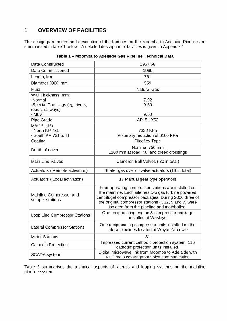
1 OVERVIEW OF FACILITIES The design parameters and description of the facilities for the Moomba to Adelaide Pipeline are summarised in table 1 below. A detailed description of facilities is given in Appendix 1.
Table 1 – Moomba to Adelaide Gas Pipeline Technical Data
Date Constructed 1967/68 Date Commissioned 1969 Length, km 781 Diameter (OD), mm 559 Fluid Natural Gas Wall Thickness, mm: -Normal -Special Crossings (eg: rivers, roads, railways) - MLV
7.92 9.50
9.50
Pipe Grade API 5L X52 MAOP, kPa - North KP 731 - South KP 731 to TI
7322 KPa
Voluntary reduction of 6100 KPa Coating Plicoflex Tape
Depth of cover Nominal 750 mm 1200 mm at road, rail and creek crossings
Main Line Valves Cameron Ball Valves ( 30 in total)
Actuators ( Remote activation) Shafer gas over oil valve actuators (13 in total)
Actuators ( Local activation) 17 Manual gear type operators
Mainline Compressor and scraper stations
Four operating compressor stations are installed on the mainline. Each site has two gas turbine powered
centrifugal compressor packages. During 2006 three of the original compressor stations (CS2, 5 and 7) were
isolated from the pipeline and mothballed.
Loop Line Compressor Stations One reciprocating engine & compressor package installed at Wasleys
Lateral Compressor Stations One reciprocating compressor units installed on the lateral pipelines located at Whyte Yarcowie
Meter Stations 31
Cathodic Protection Impressed current cathodic protection system, 116 cathodic protection units installed.
SCADA system Digital microwave link from Moomba to Adelaide with VHF radio coverage for voice communication
Table 2 summarises the technical aspects of laterals and looping systems on the mainline pipeline system:
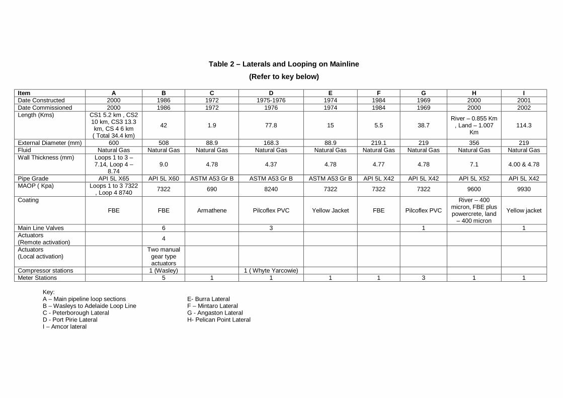
Table 2 – Laterals and Looping on Mainline (Refer to key below)
Item A B C D E F G H I Date Constructed 2000 1986 1972 1975-1976 1974 1984 1969 2000 2001 Date Commissioned 2000 1986 1972 1976 1974 1984 1969 2000 2002 Length (Kms) CS1 5.2 km , CS2
10 km, CS3 13.3 km, CS 4 6 km ( Total 34.4 km)
42 1.9 77.8 15 5.5 38.7 River – 0.855 Km
, Land – 1.007 Km
114.3
External Diameter (mm) 600 508 88.9 168.3 88.9 219.1 219 356 219 Fluid Natural Gas Natural Gas Natural Gas Natural Gas Natural Gas Natural Gas Natural Gas Natural Gas Natural Gas Wall Thickness (mm) Loops 1 to 3 –
7.14, Loop 4 – 8.74
9.0 4.78 4.37 4.78 4.77 4.78 7.1 4.00 & 4.78
Pipe Grade API 5L X65 API 5L X60 ASTM A53 Gr B ASTM A53 Gr B ASTM A53 Gr B API 5L X42 API 5L X42 API 5L X52 API 5L X42 MAOP ( Kpa) Loops 1 to 3 7322
, Loop 4 8740 7322 690 8240 7322 7322 7322 9600 9930
Coating
FBE FBE Armathene Pilcoflex PVC Yellow Jacket FBE Pilcoflex PVC
River – 400 micron, FBE plus powercrete, land
– 400 micron
Yellow jacket
Main Line Valves 6 3 1 1 Actuators (Remote activation) 4
Actuators (Local activation)
Two manual gear type actuators
Compressor stations 1 (Wasley) 1 ( Whyte Yarcowie) Meter Stations 5 1 1 1 1 3 1 1
Key: A – Main pipeline loop sections E- Burra Lateral B – Wasleys to Adelaide Loop Line F – Mintaro Lateral C - Peterborough Lateral G - Angaston Lateral D - Port Pirie Lateral H- Pelican Point Lateral I – Amcor lateral
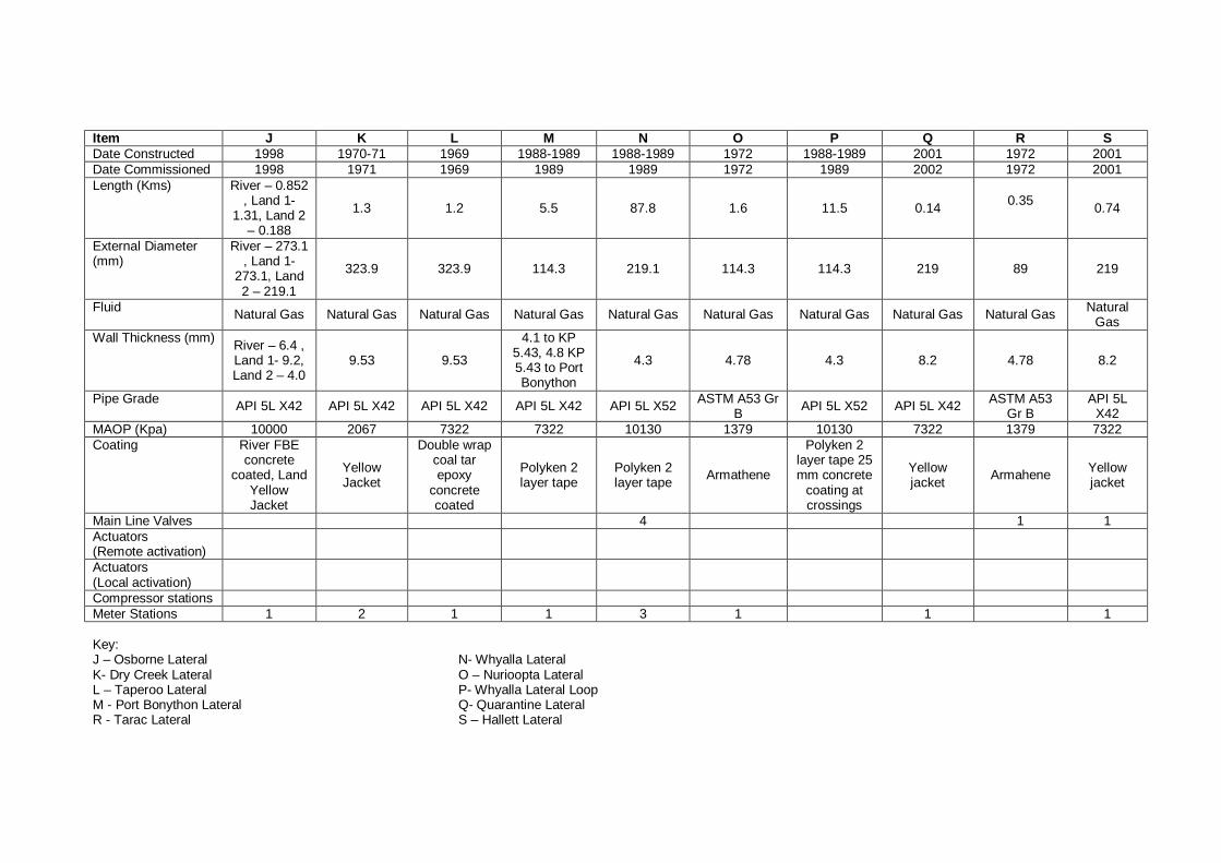
Item J K L M N O P Q R S Date Constructed 1998 1970-71 1969 1988-1989 1988-1989 1972 1988-1989 2001 1972 2001 Date Commissioned 1998 1971 1969 1989 1989 1972 1989 2002 1972 2001 Length (Kms) River – 0.852
, Land 1- 1.31, Land 2
– 0.188
1.3 1.2 5.5 87.8 1.6 11.5 0.14 0.35 0.74
External Diameter (mm)
River – 273.1 , Land 1-
273.1, Land 2 – 219.1
323.9 323.9 114.3 219.1 114.3 114.3 219 89 219
Fluid Natural Gas Natural Gas Natural Gas Natural Gas Natural Gas Natural Gas Natural Gas Natural Gas Natural Gas Natural Gas
Wall Thickness (mm) River – 6.4 , Land 1- 9.2, Land 2 – 4.0
9.53 9.53
4.1 to KP 5.43, 4.8 KP 5.43 to Port Bonython
4.3 4.78 4.3 8.2 4.78 8.2
Pipe Grade API 5L X42 API 5L X42 API 5L X42 API 5L X42 API 5L X52 ASTM A53 Gr B API 5L X52 API 5L X42 ASTM A53
Gr B API 5L
X42 MAOP (Kpa) 10000 2067 7322 7322 10130 1379 10130 7322 1379 7322 Coating River FBE
concrete coated, Land
Yellow Jacket
Yellow Jacket
Double wrap coal tar epoxy
concrete coated
Polyken 2 layer tape
Polyken 2 layer tape Armathene
Polyken 2 layer tape 25 mm concrete
coating at crossings
Yellow jacket Armahene Yellow
jacket
Main Line Valves 4 1 1 Actuators (Remote activation)
Actuators (Local activation)
Compressor stations Meter Stations 1 2 1 1 3 1 1 1
Key: J – Osborne Lateral N- Whyalla Lateral K- Dry Creek Lateral O – Nurioopta Lateral L – Taperoo Lateral P- Whyalla Lateral Loop M - Port Bonython Lateral Q- Quarantine Lateral R - Tarac Lateral S – Hallett Lateral

2 MANAGEMENT SYSTEMS 2.1 SAFETY MANAGEMENT SYSTEMS Epic Energy demonstrates effective management of health and safety risks through the development and implementation of Safe Operational Procedures and Work Instructions. Epic Energy’s Health and Safety Policy is shown in Appendix 2. The Safety Management System (SMS) developed and implemented at Epic Energy provides all Epic Energy personnel with a framework for the Management of health and safety related risks on facilities operated by Epic Energy, including the Moomba to Adelaide Pipeline (MAP) System.
The Safety Management System provides guidance to personnel at all levels of the organisation, to ensure that all activities on site are undertaken safely. It is an integral part of the overall management system at Epic Energy, designed to complement other systems in order to facilitate the management of safety and risk at each facility. The Safety Management System also provides a means for review of individual performance and a mechanism for continuous improvement of operational performance. The Safety Management System is periodically reviewed and updated as a result of operational, personnel, legislative and/ or management changes. A revised Safety and Operating Plan was issued in March 2007. Epic Energy also audit and monitor compliance with the safety management system at regular intervals. 2.2 ENVIRONMENTAL MANAGEMENT SYSTEMS The definition of environment is all encompassing and includes the air, water, land, natural resources, flora, fauna and social, heritage and economic aspects, so the area of expected responsibility, behavior and compliance with laws and regulations is quite diverse and is always changing as business and community knowledge and expectations develop. Epic’s Environmental Management System (EMS), underpins, facilitates and enhances the company’s environmental programmes. Epic's EMS consists of a number of levels of documentation (including plans and procedures) that together form the framework that is the tool for the management of the environment Epic works in. The EMS is based on Australian Standard/New Zealand Standard ISO14001:1996. In short, the EMS should be viewed as tool to manage environmental responsibilities, issues and the risks associated with Epic's operational activities such as: • Pipeline construction (including route selection, design, land access and construction
activities) • Pipeline operations • Operation of ancillary facilities Currently Epic’s EMS is being refreshed and the following key aspects are being reviewed: • Planning for continuous improvement • Implementation and operation • Checking and corrective action • Performance Review
Epic Energy has a corporate culture which stresses environmental, health and safety excellence and makes this the responsibility of every employee and contractor The South Australian Petroleum Act 2000 and Regulations require that all regulated activities carried out under the Act must be covered by an approved Statement of Environmental Objectives (SEO) and an Environmental Impact Report (EIR). In March 2003 an Environmental Impact Report (EIR) and a draft SEO were prepared to meet the regulatory requirements for the operation of the pipeline. The EIR provided: • A description of the pipeline and facilities • Described the specific features of the environment that can reasonably be expected to be
affected by pipeline operational activities • Proposes measures to mitigate potential environmental impacts and consequences • Summarises stakeholder consultation • Identified potential environmental impacts and consequences
The SEO was developed in conjunction with the EIR to outline the environmental objectives that Epic Energy is required to achieve and the criteria upon which the objectives are assessed. The objectives stated in the SEO were: • To minimise the environmental damage from the activities involved in the construction or
operation of transmission pipelines in transporting hydrocarbon products. • To establish appropriate consultative processes involving people directly affected by
regulated activities and the public generally • To promote adherence to AS2885 as a primary means of achieving public, environmental
and safety objectives • To protect the public from risks inherent in regulated activities.
Both the EIR and SEO have been approved. All operational activities on the MAPS are conducted in accordance with the SEO. Epic Energy’s Environmental Policy is provided in Appendix 3. 2.3 LANDOWNER LIAISON An integral part of Epic Energy’s Environmental Management System and to ensure compliance is landowner liaison. There are a total of 643 landowners crossed by the Moomba to Adelaide Pipeline System. A property owner contact scheme is operated where each owner or occupier along the MAPS pipeline is visited annually and in addition contacted at least twice annually by mail. Other contacts, made by Field Maintenance Officers and Superintendents during the course of daily business, are recorded in the Land Management System (LMS). Land Management is supported by dedicated LMS software which is linked to a GIS system. All property details and notes relating to discussions or issues with the property owners are recorded in the LMS. All property owners are provided with pipeline safety awareness information brochures, which contain the "Dial before You Dig" contact phone number and strongly reinforce safe working practices near high pressure pipelines.
Public pipeline Safety Awareness Presentations for the MAPS are held throughout the year. These presentations are provided to local Councils, utilities, contractors and emergency service providers. The focus of these presentations are on the specific nature and characteristics of the products carried by the MAPS, the route of the pipeline, basic information about the pipeline and its monitoring, control and emergency procedures and what notifications are required to be adhered to when working in the vicinity of the pipeline easement.
2.4 EMERGENCY RESPONSE MANAGEMENT Epic Energy maintains an emergency response capability designed to ensure that Epic Energy: • minimises or eliminates any danger or risk to individuals, • minimises or eliminate any risk to the business, and • ensure that the pipeline system is returned efficiently to a safe, operational state, with
minimum customer and environmental impact. 2.4.1 EMERGENCY RESPONSE To ensure that the pipeline system is returned efficiently to a safe, operational state with minimum customer and environmental impact Epic Energy maintain a comprehensive team structure, equipment and services, that is available and tested regularly to fine tune it’s responsiveness to emergency events. To enable this, the Emergency Response Manual and the mapped business process of responding to breakdown and emergency are utilised. The Emergency response manual is reviewed and audited regularly with the last review and updated version released in November 2006 The Emergency Response Plans provide an Emergency Management Overview detailing the Epic Response Notification and the Emergency Management Team supplemented by the State response recovery plans. Epic Energy's Emergency Response process is based on an Incident Command System that work towards the establishment and maintenance of a uniform, fully integrated, well coordinated, response effort. Its aim is to move the response from a reactive to a proactive mode of operation as quickly and efficiently as possible. By addressing the needs of an emergency as a project, the techniques and benefits of project management are utilised in achieving this aim. Epic review and test its preparedness to respond to an emergency as follows: • Two exercises will be conducted annually on pipelines including those other than PL1. • A full emergency exercise will be conducted once every two years on PL1 exclusively. • Routine inspection/testing of pipeline emergency response equipment 2.4.2 EMERGENCY RESPONSE DRILLS Emergency response procedures, equipment and materials are maintained to allow a prompt and effective response to any emergency situation, which may develop on the MAPS. The procedures are regularly tested to provide training for involved personnel and as a check that the response plans and procedures ensure an effective response. The following emergency response exercises have been conducted on the MAP over the past five years:
• In 2003 (EPIGAS) completed at Peterborough • In 2005 (Operation Cadweld) conducted on the MAP • In 2006 (Operation Flinders) was undertaken incorporating both the MAPS and PL2 • In 2007 (MAPS Local Response) was undertaken on the Dry Creek lateral on the MAP A real emergency was declared in 2006 when a stem seal on MLV25 on the Moomba to Port Bonython Liquids Pipeline leaked discharging product to the atmosphere and prompting an emergency response. The root cause of the leak was failure/ degradation of the seal due to age. While this item was not on the MAPS it did test Epic’s ER procedures in various common areas in terms of first response, management of situation and notification processes. 2.5 MAINTENANCE PLAN Epic Energy’s Maintenance Plan is designed to provide timely, quality and cost-effective maintenance and technical guidance in support of the pipeline operation. The programme outlines Epic Energy’s maintenance organisation, detailing maintenance commitment, resource structure and work control philosophy. The maintenance programme outlines the maintenance to be performed on varying types of asset, detailing the frequency, duration, plant condition, type of maintenance action, rationale behind the activity to be undertaken and technical expertise required for the task. The resource structure details the types of resource available and the responsibilities in the maintenance organisation. The work control philosophy details the methodology on how the work is to be controlled. MAXIMO is the Computerised Maintenance Management System (CMMS) utilised to implement the Maintenance Program. This is a work management tool for planning, scheduling, executing, controlling and recording the maintenance work. 2.6 TRAINING Epic Energy’s strategy is to ensure all operations and maintenance staffs are trained and competent in the tasks for which they are employed to perform. Annual individual training programs are developed for each employee from a skills/competency matrix to identify safety and technical training needs. Training and competencies programs are monitored in monthly reports and measured against corporate Key Performance Indicators (KPI’s). 2.7 INTEGRITY MANAGEMENT PLAN An Integrity Management Plan (IMP) has been prepared to identify integrity hazards and the appropriate monitoring, mitigation and inspection activities necessary to ensure safe, reliable and environmentally responsible operation of the pipeline and compliance with the requirements of AS2885. It considers the buried pipelines, main line valves, pig launchers and receivers but excludes above ground facilities such as compressor and meter stations. The specific aims of the IMP are to: • Identify the potential failure modes. • Apply appropriate activities to monitor, mitigate and inspect degradation. • Determine the appropriate frequency of application of monitoring, mitigation and
inspection activities.
• Maintain pipeline risk to “As Low As Reasonably Practicable (ALARP)” This IMP is currently in draft and being tested against the operations business activities. The IMP may be further optimised depending on business needs. 2.8 CONTRACTOR/VENDOR MANAGEMENT SYSTEM Epic Energy demonstrates effective management of contractors/vendors and minimises risk through the development and implementation of a pre-qualification process. Epic Energy is committed to achieving a fair, effective and efficient contractor/vendor management process that minimises risk whilst ensures compliance with Epic’s operational, safety and environmental objectives and obligations. The contractor/vendor pre-qualification process requires that each party provides information to Epic Energy to enable the assessment of the ability to meet performance expectations. The selection process at Epic Energy provides all personnel with risk assessment techniques consistent with Epic Energy’s risk management process, in order to determine the level of risk exposure and the evidence/documentation required from vendors. The Contractor/Vendor Management System also provides a means for review of performance and a mechanism for continuous improvement of compliance. The system is periodically reviewed and updated as a result of operational, personnel, legislative and/ or management changes. Epic Energy also audit and monitor compliance with this system on regular intervals. Further work is planned on this important system to improve its effectiveness moving forward.
3 RISK MANAGEMENT Epic Energy has been identifying, assessing and addressing hazard’s and risks associated with the operation of the MAPS since it assumed ownership of the MAPS in 1996. These tasks have been performed using both in house and external resources. A detailed Risk Assessment of the Pipeline System commenced in late 2006 and was completed in August 2007. This risk assessment was undertaken by qualified and experienced Epic Energy staff and contractor personnel for the whole of the pipeline in accordance with Australian Standard AS2885.1, additional requirements of the Draft AS 2885.1 DR 04561] ref 3 was taken into consideration. The objectives of the risk assessment were to: • Review the land use and activities in the areas adjacent to the pipeline. • Systematically identify threats to the pipeline that result in loss of integrity. • Review the external interference protection and other design/ procedural protection
measures and assess their effectiveness. • Propose additional design/procedural protection and/or mitigation measures if required. • Assess the risks resulting from threats to the pipeline integrity classified as failure events. The scope of the risk review included all buried sections of the pipeline plus, scraper stations and main line valves facilities. Each of these stations were subject to a HAZOP in 2002. The risk review focused on the threats to pipeline integrity from location specific and non location specific activities and conditions during the pipeline’s operations. The review was conducted in
the following manner: • The pipeline ROW were examined starting at Moomba and working southwards in
sections. The sections were derived based on landownership or location class. In each case the pipeline’s route for that section was traced from end to end using the Epic Energy GIS and the location class reviewed.
• Each threat identified during previous risk assessments and recorded in the GIS were reviewed to determine whether the threat is still applicable, if the protection measures are still applicable and whether the risk associated with the threat was reduced by the protection measures to an acceptable level.
• The noted threats, protection measures and risk evaluations were updated directly into the GIS where it was identified that the previous records were no longer considered appropriate.
• Any additional threats not previously noted in the GIS were added to the GIS, together with the applicable protection measures and risk evaluation.
• Where additional information or assessment was identified as being required applicable actions were recorded. These actions were recorded in the GIS database.
• Where the risk assessment could not be completed due to the need to obtain information then that action was tagged as “pending” in the GIS database.
The risk assessment found that in most cases the protection measures in place reduced the risk of the identified threats to as low as reasonably practicable (ALARP). The following threats were deemed hazardous events and were risk ranked using the AS2885 risk matrix:
• Railway accidents – at KP locations as detailed in the risk assessment including
Angaston, Dry Creek, Nurioopta, Port Pirie, Tarac, Whyalla laterals, MAP and Wasleys Loop Line.
• Water and exploratory boring activities • Anchor dragging – Whyalla Lateral crossing the Spencer Gulf • Excavation activities – Port Bonython, Port Pirie and Whyalla Laterals • Maintenance activities by third parties adjacent to pipelines • Maintenance by third parties over the pipeline The following conclusions were determined from the risk assessment: • For the majority of threats to the pipelines the protection measures reduce the risks to as
low as reasonably practicable (ALARP). • The signage spacing generally complied with for R1 classifications. For other location
classifications and for some R1 locations an action was raised where signage did not comply with standard signage requirements.
The risk assessment recommended: • All previous AS2885 risk assessment actions require verification of being suitably
completed and closed out. • The GIS should be updated such that the threat analyses for typical designs are reflected
for each occasion of the representative threat. • The risk assessment should be completed for all pending threats. • Where a secondary location classification was considered to be applicable to a particular
pipeline sectional area then this should be confirmed and the impact clarified for future reference.
• The depth of cover recorded in the GIS is date stamped so that subsequent reviewers of the data can see its currency.
In relation to the station facilities the following Hazardous and Operability Studies (HAZOP’s) have been performed during the last 5 year period: • 2003 – CS4, Wasley Compressor Station, MLV 28, Beach Petroleum ROW, Balcoracana
Creek Tie-in • 2004 – Fire and Gas upgrade project commencing at CS5, actions arising from
metropolitan meter stations, actions arising from compressor station 2002/03 HAZOP. As part of the risk assessment process Epic Energy plans to carry out full HAZOP’s for its above ground facilities during 2008 and 2009. Epic has reviewed informally the previous HAZOP information and found little change has occurred to these sites since then. The Petroleum Regulations specifically refers to the risk the pipeline imposes on the following: • Public Health and Safety • Environment and • Security of Natural Gas Supply 3.1 PUBLIC HEALTH AND SAFETY The pipeline route varies between broad rural landscape and National Park where land is largely undeveloped and sparsely populated and traverses some metropolitan, regional and rural centres which are more densely populated. Epic Energy implements a Community Awareness Programme, which involves holding community awareness meetings with communities along the pipeline route. To cover the pipeline infrastructure that Epic Energy operates in South Australia including the Adelaide to Moomba Gas Pipeline, Epic target 30 meetings annually with CFS, MFS, Police, Ambulance, SES, councils, earth moving contractors, irrigation and fencing installation contractors. The presentations for the Moomba to Adelaide Gas pipeline system focus on the general properties of the natural gas, the location of the high pressure pipelines in the regions concerned, correct procedures when working within the pipeline easements, pipeline threats and dealing with emergency situations. Previous incidents that have occurred on the pipeline have included: • Minor loss of cover due to soil erosion activities • Unauthorized activity on easement due to landowner activities • Threats to pipeline integrity due to activities by third parties (e.g. fencing contractor and
quarrying). To date no incident has resulted in any significant or long term impact to the environment or members of the public. The safe design of the pipeline, routine inspections and maintenance coupled with sound management practices reduces the risk to as low as reasonably possible. 3.2 THE ENVIRONMENT Potential environmental hazards and consequences associated with the operation of the pipeline were identified in the March 2003 Environmental Impact Report. The objectives for environmental management of the pipeline are: • Avoid unnecessary disturbance to third party infrastructure, landholders or land use • Soil erosion
• Maintenance of vegetation cover on the easement • Prevent the spread of weed and disease • Water and land contamination • Minimise the risk to public health and safety • Minimise noise due to operation of the pipeline • Minimise discharge from the pipeline • Protect cultural heritage sites and values • Minimise the impact of the pipeline operations on surface water sources
The most significant contamination associated with the operation of the pipeline is the potential for land contamination from previous practices.
These included:
• the use of underground storage tanks (USTs) • contaminated discharges from triple interceptor trap systems and soakage pits • vents and bleedlines that discharge to ground Between 1995 and 1999 Epic Energy instigated an improvement programme to minimise the risk of any further hydrocarbon contamination occurring and minimize the impact of any existing contamination. Activities included:
• removal of all underground storage tanks and testing the soil for residual contamination. • Installation of leakage monitoring systems where it is not possible or feasible to remove
the UST • Establishment of landfarms to treat hydrocarbon contaminated soil • Installation of ground water monitoring bores where there was potential for contamination • Installation of groundwater remediation systems where required to remove hydrocarbon
contamination • Relining triple interceptor pits and decommissioning soakage pits • Installation of oil containment systems including bunds in compressor buildings and mist
eliminators on vents • Implementation of a monitoring programme to establish the extent of any contamination
and monitor effectiveness of the management programmes. As a result of the work described above it was identified that hydrocarbon contamination of the land and groundwater had occurred as a result of leakages from the UST’s or soakage pits. Groundwater contamination was identified at the Torrens Island Meter Station and at Compressor Stations 2 and 7. Land farms were established at Compressor Stations 1 to 5 and the Peterborough Depot to treat the hydrocarbon contaminated soil excavated during the removal of the UST’s and other remedial excavations. A number of known pre-existing potential contaminated soil sites are also present on the pipeline easement within the Adelaide metropolitan region in the industrial areas of Dry Creek and Torrens Island. To address these issues environmental monitoring works has been completed at several sites along the MAP including Compressor Stations 1-7, the Mintaro Meter Station, Peterborough Depot and Torrens Island Meter Station. This monitoring has identified: • The extent of contamination and determined that any existing contamination is not
increasing or becoming mobile • That no leaks or discharges are apparent from the underground storage tanks still in use • That land farming of hydrocarbon contaminated soils is slowly decreasing hydrocarbon
concentrations.
Through the maintenance of the monitoring programme outlined below, it is believed that the contamination can be managed to ensure that the contamination does not spread from its existing boundaries and will slowly degrade over time. The potential for the movement of water and contaminants within the trench of the MAP and associated lateral pipelines has been considered. However due to the nature of the soils and the landforms through which the pipeline pass and the installation of trench breakers during construction of the pipelines it is unlikely that sufficient water movement would occur along the trench to create these issues. The potential for the spread of existing areas of known contamination along the pipeline easement has also been considered. The nature of pipeline operations is such that the only incident in which this has potential to occur is during the excavation of the pipeline. In the event that an excavation is required on the easement, in an area of known potential contamination, consideration would be given to the management of handling the contaminated material in relation to preventing its spread into the environment and reducing the potential impact on the health of personnel and the general public. Measures that have been put in place to minimize the impact of the existing contamination and prevent any further contamination include: • Monitoring of the existing contamination and land farms on at least an annual basis • Implementing additional investigations and monitoring if it becomes apparent that
hydrocarbon contamination levels are increasing or spreading outside existing boundaries • Operation of a passive skimming unit at Compressor Station 7 to remove phased
separated hydrocarbon • Regular monitoring of underground storage tanks to ensure that integrity is maintained • Ensuring that the use and storage of hazardous substances is undertaken within
contained areas and appropriate spill containment measures are implemented • Implementation of a spill response system to promptly manage any spill of hazardous
material • Discussions of management of soil and water with appropriate regulatory authorities prior
to the commencement of excavations in areas of know potential contamination. These issues are subject to an annual assessment or audit according to the guidelines given in the SEO to determine if satisfactory environmental management is achieved. Associated with the annual dig up program that has been undertaken since 2005 on the MAPS, cultural & archeological significance surveys are undertaken in the areas where digging is planned. 3.3 SECURITY OF NATURAL GAS SUPPLY Reliability of sales gas supply to consumers depends on the Moomba Processing Plant and the MAP continuing to deliver sales gas. An incident which results in the shutdown or significant restriction in throughput due to failure of either of these facilities has the potential to adversely impact the security of supply of natural gas to South Australia. The construction of the QSN Link pipeline linking Epic Energy’s South West Queensland Pipeline (SWQP) from Wallumbilla to Ballera to the Moomba to Adelaide Pipeline will improve the security of gas supply to the MAP and South Australia. The QSN Link will be a 180km 400 mm diameter extension of the SWQP designed to transport over 250 TJ/ day.
Epic Energy operates a 24 hour /365 day a year TSCC in Melbourne which monitor all of Epic Energy’s pipelines including the MAP. All aspects of operation are monitored from the Control Centre including field travel movement and maintenance work on operational equipment. Outages on rotating equipment are planned to ensure availability of critical equipment. The systems and procedures used to manage maintenance work and third party activities, monitor pipeline condition, emergency systems and procedures are directed at eliminating or minimising the risk of a serious incident which may result in a shutdown of the pipeline.
4 PHYSICAL ASSESSMENT OF FACILITIES The Moomba to Adelaide Gas Pipeline is 39 years old and was designed and constructed to the standards and best practice principles at the time. To ensure integrity new pipelines and the existing MAPS are constructed and maintained in accordance with Australian Standard AS2885: Pipelines Gas and Liquid Petroleum. Pressure vessel integrity is maintained through the application of appropriate Australian Standards for design, maintenance and inspection. AS/NZS 3788 2006 Pressure Equipment – In - Service Inspection forms the basis of the Inspection Programme. Specialist inspection contractors are engaged to conduct inspections to this standard. Routine maintenance of mainline valves, compressor stations and meter stations is performed six monthly, all pipeline pressure regulator and over pressure protection devices are tested in accordance with relevant Australian Standards and the maintenance schedule. Ancillary equipment such as pipe supports and pigging facilities are also routinely inspected. During the time frame since the last fitness for purpose report was issued in 2003 the following physical assessment activities have been performed:
4.1 PIPELINES In addition to routine maintenance activities the following inspections were also performed: 4.1.1 INLINE INSPECTION SURVEYS AND REFURBISHMENT 4.1.1.1 MAP An In Line Inspection Survey of the MAP and the 20 inch Wasleys Loop Line commenced in May 2002 and was completed in November 2003. As expected for a pipeline of the age of the MAP the ILI tool detected a large number of anomalies and defects along the pipeline. Interpretation of this data and prioritisation of the information is crucial to ensure that high priority features are identified and targeted for physical inspection and repair. In particular the ILI tool detected a number of external corrosion features between Moomba and Compressor Stations 1 to 4. Epic Energy uses a “3 Tier “approach to assess defects as follows: • Tier 1 – This method approximates the corrosion defect as a rectangle shape based on
the length and depth of the corrosion defect as recorded by the ILI. This is the most conservative assessment method.
• Tier 2 – This method approximates the corrosion defect as a parabolic shape based on the length and maximum depth of the corrosion defect.
• Tier 3 – This method measures the effective area of the corrosion defect by recording the actual maximum depths along the entire length of the corrosion defect. Tier 3
assessments are the least conservative approach but are an industry accepted method for defect assessment.
Epic Energy applies the three tier assessment progressively from the most conservative (tier 1) to least conservative (tier 3). Any defects which fail all three tiers are targeted for inspection and repair. The most common form of corrosion on the MAP is typically pitting corrosion with numerous shallow pits covering a large surface area. The 2003 ILI inspection survey reported defects using the Tier 3 method in terms of the Estimated Repair Factor (ERF). Defects with an ERF > 1 are not acceptable to ASME B31.G/ AS 2885 and require repair. The “field verified “depth and length characteristics of each of these defects was analysed using commercial software called RSTRENG TM. Eleven of the most severe defects with ERF > 1 were excavated for further assessment and verification in 2004. Seven of these defects were located between Compressor Stations 1 and 2, two defects between Compressor Stations 2 and 3, one defect between Compressor Station 3 and 4 and one defect between Compressor Station 5 and 6. Between 2005 and 2007 further defect repair and pipeline refurbishment work was conducted. In 2005 an additional twenty five defects were excavated and repaired between Compressor Stations 1 and 2 with an ERF > 1. In 2006 a total of 48 defects were excavated and repaired. Twenty of these defects (seventeen between Compressor Station 1 and Compressor Station 2 and three defects between Compressor Station 2 and Compressor Station 3) had an ERF > 1. In 2007 a total of 45 defects were excavated and repaired, five of these defects, between Compressor Station 2 and Compressor Station 3 had an ERF>1. All defects with an ERF > 1 were repaired using clock springs. In conjunction with the defect repair programme pipeline coating refurbishment was completed at the following locations:
• 2005 : 685 metres of pipeline coating was refurbished between Compressor Station 1 and 2
• 2006 : a total of 560 metres of pipeline coating was refurbished; 39 metres between Moomba and Compressor Station 1, 370 metres between Compressor Station 1 and Compressor Station 2, 34 meters between Compressor Station 2 and Compressor Station 3, 111 metres between Compressor Station 3 and Compressor Station 4 and 6 metres between Compressor Station 4 and Compressor Station 5.
• 2007 : a total of 450 metres of pipeline coating was refurbished, 237 metres between Compressor Station 1 and Compressor Station 2, 99 metres between Compressor Station 2 and Compressor Station 3 and 114 metres between Compressor Station 3 and Compressor Station 4.
All excavated pipeline is tested for SCC using magnetic particle inspection. In 2008 it is planned to refurbish a total of 500 metres of pipeline coating between Compressor Station 1 and Compressor Station 2, Compressor Station 3 and Compressor Station 4 and Compressor Station 4 and Compressor Station 5. During the field verification programme discrepancies between the data obtained in the field compared to the data provided by the ILI tool were noted. Typically the tool underestimated the
length and depth of each defect. It was concluded that this discrepancy is due to the reporting threshold of the ILI tool being set to satisfy tier 1 and tier 2 methods but not tier 3. A large amount of work has been completed in conjunction with the ILI contractor to correct the misalignment between the ILI and field verification data and include the lessons learnt into the 2008 ILI programme. Field verification work has also shown that one defect between Compressor Station 1 and 2 at log distance 69803.22 meters, one defect between Compressor Stations 3 and 4 at log distance 90914.12 metres and one defect between Compressor Stations 5 and 6 at log distance 15409.24 require re assessment and will be prioritised for repair in 2008. Details of the features identified by the ILI survey with an ERF > 1 and the repair work conducted is summarised in Appendix 4. 4.1.1.2 ANGASTON LATERAL During August 2004 an Inline Inspection Survey was completed on the Angaston Lateral from the Wasleys Off-take to the Angaston Meter Station. A total of twenty two defects were noted, six of the most significant defects were excavated, inspected and refurbished in 2005 (results). The ILI survey detected one defect at KP 35.04 which exceeded an ERF of 1 when assessed according to modified ASME B31.G criteria using RSTRENG TM analysis. Work order 60169 states that the defect was inspected, FFP calculation performed and pipe recoated. The defects detected by the ILI and those excavated recoated and backfilled are summarised in Appendix 5. 4.1.1.3 WHYALLA AND PORT PIRIE LATERAL During August and September 2006 the lateral pipelines from Whyte Yarcowie (Port Pirie Lateral) to Bungama and Bungama to Whyalla (Whyalla Lateral) were inspected using the ILI tool. No defects on either pipeline were detected with and ERF greater than 1. Further work is planned to investigate the external corrosion defect on the Whyte Yarcowie to Bungama Lateral at log distance 18228.88 metres due to it’s length and the two internal corrosion defects at log distances 53919.77 and 41600.06 metres. One significant defect was detected on the Bungama to Whyalla Lateral. This is an internal metal loss milling feature at log distance 11979.48. Four defects were found under the Spencer Gulf, two were metal loss milling features, one a milling feature and one defect an ID anomaly. These defects and twenty minor defects will be considered for further investigation in conjunction with coating defect verification digs and inspections planned during 2008/09. Details of eleven of the most significant features detected by the ILI survey are summarised in Appendix 6. 4.1.2 CLEANING PIG OPERATIONS The gas received for the MAPS is low in water content and corrosive gases. Pipeline pigging to remove accumulated water and sludge is typically carried out prior to ILI surveys being performed.
4.1.3 DCVG COATING SURVEYS AND DIG UPS From 2003 to 2007 the following above ground coating defect (DCVG surveys), inspection and refurbishment was conducted on the following pipelines:
• Wasleys to Torrens Island Loop Line • Taperoo Lateral • Dry Creek Lateral • Downstream Moomba to KP30 • Downstream Compressor Station 1 to KP 97.9 • Downstream Compressor Station 2 to KP191.30 • Downstream of Compressor Station 3 survey distance 22.4 km • Downstream of Compressor Station 4 to KP 382.8 • Downstream of Compressor Station 5 survey distance 26.8 km • Downstream of Compressor Station 6 survey distance 22.5 km • Downstream of Compressor Station 7 survey distance 20.2 km • Pelican Point Lateral • Osborne Lateral • Whyte Yarcowie to Whyalla • Angaston Lateral • Burra Lateral • CS3 Loop • Peterborough Lateral The purpose of this work is to determine the condition of the coating, assist in assessing whether SCC could be a factor and to validate the performance of the cathodic protection systems. No significant corrosion or expected impacts for SCC was noted. In a number of instances the coating was found to have deteriorated in condition. Verification digs will be conducted on a further number of these pipelines during 2008 to assess the effectiveness of the cathodic protection systems, enable a comparison between ILI surveys and field results and inspect for stress corrosion. A summary of the defects identified by the DCVG surveys, refurbishment work conducted and taken is given in Appendix 7. 4.1.4 CATHODIC PROTECTION The cathodic protection systems are maintained by field based technicians who monitor the operation and performance of the cathodic protection systems and Adelaide based engineers who provide long term direction and specialist engineering support. Performance of the pipeline cathodic protection systems are monitored by: • Two monthly, by function testing the cathodic protection units for correct operation and
adjustment of output. • Six-monthly by conducting ON/OFF potential surveys at all test points, to determine the
level of protection achieved. Adjustments are made to the cathodic protection systems to achieved the protection criteria of -0.850 V to -1.200 V instantaneous OFF potential versus copper/copper sulphate half cell as required by Australian Standard AS2832.
A review of the cathodic protection data shows that the majority of the pipeline is satisfactorily protected however improvement is required in a number of areas to restore protection levels. These areas exist predominately at locations where ground beds have failed or output is reduced, compressor station inlets and outlets possibly due to interference with earthing systems and locations where the pipeline coating has deteriorated.
These locations include: • Compressor Stations 1 (KP 67.7), 4 (KP 352.7), 7 (KP 638.2) and Wasleys (KP 731.8). • Low protection levels between Compressor Station 3 (KP 256.1) and Compressor Station
4 (KP 352.7) • Compressor Station 1 Loop Line ( KP 69.1) • Low protection levels Angaston Lateral. Interference testing conducted in the Moomba Area between the MAP and Santos flow lines in 2007 concluded that the level of interference measured on the various pipelines is due to electrolytic interference from negative soil voltage gradients associated with poorly coated pipelines at adjacent pipe crossings. The level of anodic interference in many cases exceeds the +20mv shift as specified in Australian Standard 2832.1. The majority of pipelines are sufficiently negative to offset this minor anodic shift without compromising the level of protection of the pipeline to any significant degree. If protection levels are compromised then this will be addressed via resistive bonds between the pipelines and or coating refurbishment at pipe crossings. The programmes planned during 2008/9 to rectify protection levels which are not satisfactory include: • Continuation of the ground bed replacement programme. • A current attenuation survey was performed in 2007 between Compressor Stations 3 and
4. The most likely locations being at KP266 and KP316 between the existing cathodic protection units at Dingo Lake, Munyallina, Wertaloona and Moorowie Bore.
• An audit against AS2832 is planned during 2008 to identify priority issues. The audit will include an assessment of cathodic protection system effectiveness and hardware function, ground bed remaining life assessments, pipeline electrical isolation, an on /off pipe to soil potential survey and further interference testing.
• A review or earthing and surge protection systems for compatibility with cathodic protection systems and personnel protection from high transient voltages and low frequency induced AC.
• The installation of cathodic protection system interrupter’s to enable the synchronisation of cathodic protection units for instantaneous off potential measurement.
• Cathodic protection shielding occurs when dis-bonded coating prevents cathodic protection current from reaching deep inside a corrosion defect. External corrosion due to CP shielding has been identified as a risk to the integrity of the MAPS. It is planned to investigate CP shielding in conjunction with coating refurbishment programmes.
It is worth noting that due to the deterioration of the pipeline coating the current required to protect the MAP has increased by approximately fifteen times from an average of approximately 70 µ A / m 2 to 1100 µ A / m 2 since the pipeline was commissioned in 1970. The number of cathodic protection units has increased from thirteen to one hundred and sixteen. The MAP off potential survey results for 2003 to 2007 is given in Appendix 8 and a summary of ground beds replaced (including laterals) is given in Appendix 9. 4.1.5 STRESS CORROSION CRACKING (SCC) A programme to investigate higher risk areas for possible SCC locations downstream of compressor stations was carried out in 2004. Discharge pressure and temperature data from each compressor station was used to establish the most likely location of SCC. A DCVG survey programme was conducted on areas up to 30km downstream of each compressor station and dig ups performed to inspect for SCC in conjunction with the ILI defect repair programme. No
evidence of SCC has been detected. Inspection for SCC was also conducted on other sections of the MAP in conjunction with refurbishment work following DCVG surveys in 2003 and 2004 and the defect repair and refurbishment programmes in 2005, 2006 and 2007. No evidence of SCC has been detected. 4.1.6 PIPELINE SUBSIDENCE PROJECT This project investigated the subsidence of underground pipe work at MAP Compressor Stations and in particular the pipe work connecting the mainline, the station anchor blocks, pig launchers and receivers, the inlet and outlet valves and the MLV. During 2004/05 an action plan was developed which included: • Data gathering, site inspection, crack testing NDT, FEA stress analysis and hydotesting
similar pipe to station pipe work to destruction for FEA model verification. Pipe work at CS6 and CS7 was excavated and inspected as these two sites were identified to be the only two requiring remedial work due to the extent of the subsidence.
• Pipe subsidence was concluded to be a combination of anchor block sinkage and no soil support under by pass pipe work coupled with soil load on top of the pipe. The mainline tees are additionally stressed due to these bending loads. The tees are non standard, short radius fittings, but comply with ASME B31.8 Analysis showed that the tees are fit for purpose under the combined bending and pressure loads.
• Corrective action was taken by the installation of supports under pipe work to lock pipe work in place to prevent further settlement and loading of the pipe work. All affected pipe work was blasted and 100% NDT inspected. Concrete supports were constructed and permanent survey monitoring points installed to ensure the earliest possible identification of future problem areas.
In 2006 a final FEA analysis report was prepared which concluded that subsidence should be checked annually at CS1, 2, 3, 4, 5, 6 and 7 and an engineering assessment completed. This now forms part of the annual maintenance plan. 4.1.7 UNDERWATER AND CASED CROSSINGS Underwater crossing inspections are carried out annually on the Whyalla Lateral crossing of Spencer Gulf, the Wasleys to Adelaide Loop line crossing of the Barker Inlet and the Taperoo, Pelican Point, Osborne Lateral crossings of the Port River. There have been no significant issues raised from these reports. 4.1.8 PIG LAUNCHERS AND RECEIVERS Programmes to inspect pig launchers and receivers were completed in 2002/03 and 2005. Vessels were externally inspected; internal inspections were carried out where access was possible or by ultrasonic inspection. A number of vessels were found to have minor external corrosion and surface rust. Pig Launchers and receivers, although not registered pressure vessels are included in the registered pressure vessel inspection programme. Pig launchers and receivers are also externally inspected and function tested at six monthly intervals as part of the routine maintenance programme. Internal and external Inspections due in 2007 have been deferred until 2008 pending a review of inspection practices and a move to risk based inspection.
4.2 PRESSURE VESSELS AND FACILITIES 4.2.1 PRESSURE VESSELS Epic Energy operates approximately 200 registered pressure vessels and associated piping on the MAPS. Equipment integrity is maintained through the use of Australian Standard for design, maintenance and inspection AS/NZS 3788 “Pressure Equipment In Service Inspection“. This standard forms the basis of the inspection programmes which are carried out by specialist NDT contractor’s who typically inspect pressure vessels on a set frequency of 2 years for external inspections and 4 years for internal inspections. As stated above the practice of inspecting pressure vessels at a set frequency are currently being reviewed and a move to risk based inspections likely in line with industry practice. A programme of inspecting MAPS registered pressure vessels was completed in 2002/03 and 2005. Vessels were externally inspected; internal inspection was carried out where access was possible or by ultrasonic inspection. A number of vessels were found to have minor external corrosion and surface rust. 4.2.2 METER STATIONS A programme was completed at all major meter stations during 2003 to replace antiquated process instrumentation equipment. In 2005 an earthing and lightening project was completed on all metropolitan meter stations to establish an external earth grid and achieve equipotential bonding between instrument and site structures and the earth grid. The Whyalla, Burra, Torrens Island, Taperoo, Virginia meter stations underwent recoating (painting) in 2003. Meter station facilities at Douglas Point, Mambray Creek, Port Pirie, Bungama, Elizabeth, Nuriootpa, Pelican Point and Port Bonython underwent a recoat of all above ground pipe work and equipment in 2004. 4.2.3 COMPRESSOR STATIONS During 2003 an extensive boroscope inspection programme was undertaken to identify gas turbine related problems at CS1, 2, 3 4, 5 and 6. The programme identified some problems with the Allison engines at CS3, 4 and 6 requiring combustion liner replacements. In 2007 further boroscoping and thermal imaging was completed on the MAPS units at CS 1, 3, 4, 6 and Whyte Yarcowie. Information from this program is being assessed and remedial action being undertaken as necessary. In 2005 an earthing and lightening project was completed on Compressor Station 7, Angaston and Wasleys Compressor Stations to establish an external earth grid and achieve equipotential bonding between instrument and site structures and the earth grid. Sites upstream of CS7 were completed in 2002. Painting of above ground pipe work at Compressor Stations 3 was completed in 2005. Compressor stations control room facilities were upgrade in 2004. During 2006 Epic Energy commenced a programme of mothballing CS 2, 5 and 7 due to predicted lower output. These sites were isolated from the main pipeline, compressor units placed in preserved condition and all ancillary gas supplies isolated from the turbine units and the
sites powered valves. 4.2.4 MAINLINE VALVES Routine main valve maintenance including valve sealing integrity checks, stem and ball seal greasing, valve operational checks and valve serviceability checks are completed at six monthly intervals. 4.3 PIPELINE MONITORING SYSTEM (COMMUNICATIONS SCADA) Routine maintenance tasks that occur at the communications facilities consist of: • Annual micro wave, VHF & UHF radio system performance checks • Electrical checks at the site radio hut facilities • Three and six monthly uninterruptible power supply system inspections and checks
including battery maintenance. • Guy rope tensioning and replacement as required to ensure the tower ropes are tensioned
as per the original design specification and to correct any misalignment that may have occurred over time.
• Radio tower three yearly routine maintenance inspections. This work involves a physical inspection of the radio tower structure and replacement as required including all ancillary equipment such as antennas, tower cabling, cable trays, mast lighting and corrosion issues.
• Painting of towers 4.4 RIGHT OF WAY 4.4.1 SIGNAGE An ongoing program has been developed to upgrade the signage along the entire length of the Pipeline to 500 metre spacing to comply with AS 2885. Routine maintenance will ensure the signs are maintained to the required standard. All compounds are clearly identified with signage indicating what the facility is and who to contact in the event of an emergency. 4.4.2 MAINLINE VALVE COMPOUNDS Routine maintenance is carried out on MLV compound fences and gates as part of the ROW patrols with corrective actions followed up as required. 4.4.3 WEED CONTROL Weed identification and control is performed as part of ROW patrols, additional contract resources are engaged to monitor and control the African Rue in the vicinity of compressor station 5. 4.4.4 AERIAL SURVEILLANCE High risk areas (metropolitan) aerial surveys are completed monthly and a quarterly patrol up to CS4 completed every 3 months.
4.4.5 ROAD PATROLS Road patrols are daily in high risk metropolitan areas and two weekly, monthly or three monthly as determined by the AS 2885 risk assessments and after heavy rains in other areas as determined by the risk assessment process.
Road maintenance is performed as required in areas where the ROW is used as the pipeline access track. 4.4.6 PIPELINE LOCATION SERVICE Epic Energy subscribes to the Dial-Before-You-Dig programme and offers a free pipeline location service. The remoteness of this pipeline results in a limited number of applications for this service in the northern remote areas, and between 450 & 500 requests annually for services in the built areas south of Peterborough. Cooperation with the community has been excellent in this matter. 4.4.7 LANDHOLDER CONTACT PROGRAM Every twelve months all property owners and local councils along the pipeline are visited and sent pipeline awareness correspondence and brochures as part of a contact scheme. The scheme is intended to remind and keep property owners abreast of the potential hazards associated with high pressure pipelines and the rules and obligations associated with landowner activity in the vicinity of the pipeline. Epic Energy implements a Community Awareness Program, which entails holding awareness meetings with communities along the pipeline route. To cover the various pipeline infrastructure that Epic Energy operates and maintains in South Australia Epic Energy had set an annual national target of a minimum 30 meetings annually with CFS, MFS, Police, Ambulance, SES, councils, earth moving contractors, irrigation and fencing installation contractors. 4.4.8 WASH OUTS Washouts are identified through routine patrols and site visits for maintenance. During this reporting period several sections of the pipeline have been subject to erosion resulting from heavy rains and flooding reducing the pipeline depth of cover. Repairs were carried out at the first opportunity as a priority after the wash outs are identified. 4.8 SINGLE WIRE EARTH RETURN SYSTEMS Annual maintenance performed by a specialist contractor is completed on sections of the SWER line each year. Any corrective action is undertaken and a SWER line technical audit report is required to be provided to the Office of Technical Regulator (OTR) every two years on this system for compliance related matters.
5 EFFECTIVENESS OF MANAGEMENT SYSTEMS The Epic Energy Environmental Health and Management System are compliant with Australian Standard AS4801:2000 Occupational Health and Safety System. The EHSMS comprises of core management standards which apply to matters of the environment, health, safety and security of production and to all business aspects of its operation. The EHSMS comprises detailed hazard standards for environment and health and safety. These standards address the key hazards presented within the Epic Energy operation and document the
control required to adequately manage these hazards. EHSMS assessments are conducted by independent external auditors when required. 5.1 AUDITS AND REPORTS 5.1.1 OPERATIONS AND MAINTENACE AUDIT During September 2007 an internal Operations and Maintenance Audit was conducted. The audit was conducted to review Epic Energy’s systems and procedures for compliance with the requirements of AS2885.3. The following audit methodology was undertaken: • A desktop audit was conducted at the Epic Energy Dry Creek office to review and assess
existing procedures and records • A field assessment was conducted of the pipeline facility and a small section on the right
of way. • A formal assessment report was prepared. Key finding from this audit included: • The audit determined that Epic Energy has a set of operating procedures for the conduct
of operations, maintenance, monitoring and provision for engineering services for the pipeline. Epic Energy aims to operate in accordance with AS2885.3 guidelines and has in general met the intent of the standard.
• Certain procedures and work instructions were not available and some procedures were incomplete.
• Personnel are adequately trained and qualified to carry out their duties with the aid of the Competency Based Training System.
• Some job plans had insufficient information to accurately identify the work required and some work instructions lacked detail.
• The absence of some approved procedures and work instructions prevented full compliance with the requirements of AS2885.3
The findings from this audit are being addressed. 5.1.2 OTHER GENERAL AUDITS In addition to the specific operations and maintenance audit, a number of other system control audits are conducted by Epic Energy as part of the normal annual business audit program. Some of these included auditing off: • Integrity of Compressor Station Audit – Thermal Imaging & Boroscoping • Effectiveness of ERP manual • Review and effectiveness of compliance of metering equipment via AVT process • Safety related audits in Trenching & Excavation, Working at Height, Personnel Tracking
Movements etc. • Status of work program against annual maintenance plan Corrective actions from these audits are addressed as required. 5.1.3 SAFETY MANAGEMENT SYSTEM AUDIT An internal audit of Epic Energy’s safety management system is conducted on an annual basis. Results of the audit are circulated to senior management for delegation of the close out actions.
The status of action items is checked for completion on a regular basis prior to the commencement of the following year’s audit. There are no outstanding issues related to the MAPS requiring follow up.
5.1.4 ENVIRONMENTAL AUDIT An internal audit of Epic Energy’s compliance against its environmental objectives (SEO) is completed annually. An external environmental audit was conducted on all compressor station facilities in 2005. The audit determined that Epic Energy complied with its environmental objectives and recommended that future external audits be performed biannually. In May 2007 an Environmental Audit was conducted of the MAP between Moomba and Compressor Station 4 in conjunction with an Environmental Audit of the Moomba to Port Bonython Liquids Pipeline. No major non-compliances with the SEO were noted. Findings relating to the MAP included: • Epic Work Instruction WM 02-134 Excavation of Liquid and Gas Pipeline Systems be
revised to reflect revisions to the Environmental Management System and include a requirement to complete a disturbance checklist.
• Regular training sessions be provided to Epic personnel and contractors on the requirements of the EHS
• A weed control program be initiated at Compressor Station 1 to prevent further outbreaks of Caltrop.
• Records relating to the management of soil farms at Peterborough and Compressor Stations need to be updated to reflect current practice.
• Expired batteries should be removed to an appropriate waste depot for disposal to reduce the risk of spills or injury.
• Procedures should be updated as required to include requirements for undertaking heritage investigations of pipeline easements and for the accidental discovery of heritage sites.
6 ASSUMPTIONS AND SENSITIVITIES This report specifically addresses the Fitness for Purpose of the MAP. Certain assumptions have been made: The risk assessments conducted by Epic Energy personnel or consultants relate to the consequence and likelihood applied to the various risk scenarios assessed. Risk assessments are conducted based on the two dimensional matrix given in AS4360. Where it is possible historical data is used to determine the possible extent of disruption to the pipeline and the level of consequence. The likelihood of an event occurring is supported by Epic Energy’s records. In the absence of historical data best judgement has been used based upon the experience of Epic Energy personnel. As prudent pipeline operators Epic Energy personnel represent the organization in the best possible way based on their knowledge and experience. This is not to say that certain assumptions can in fact be incorrect and this should be noted.
7 IMPACT OF THE ENVIRONMENT ON THE PIPELINE The pipeline crosses a range of different landforms and land uses and is divided into the following
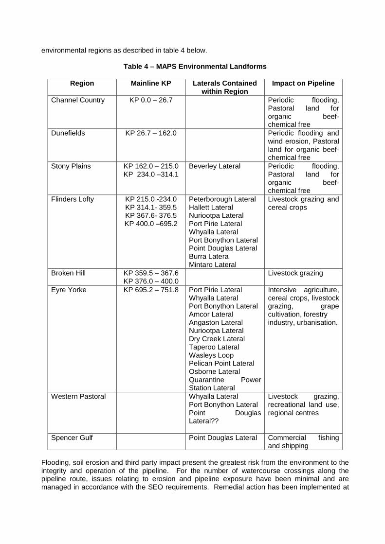
environmental regions as described in table 4 below.
Table 4 – MAPS Environmental Landforms
Region Mainline KP Laterals Contained within Region
Impact on Pipeline
Channel Country KP 0.0 – 26.7 Periodic flooding, Pastoral land for organic beef- chemical free
Dunefields KP 26.7 – 162.0 Periodic flooding and wind erosion, Pastoral land for organic beef- chemical free
Stony Plains KP 162.0 – 215.0 KP 234.0 –314.1
Beverley Lateral Periodic flooding, Pastoral land for organic beef- chemical free
Flinders Lofty KP 215.0 -234.0 KP 314.1- 359.5 KP 367.6- 376.5 KP 400.0 –695.2
Peterborough Lateral Hallett Lateral Nuriootpa Lateral Port Pirie Lateral Whyalla Lateral Port Bonython Lateral Point Douglas Lateral Burra Latera Mintaro Lateral
Livestock grazing and cereal crops
Broken Hill KP 359.5 – 367.6 KP 376.0 – 400.0
Livestock grazing
Eyre Yorke KP 695.2 – 751.8 Port Pirie Lateral Whyalla Lateral Port Bonython Lateral Amcor Lateral Angaston Lateral Nuriootpa Lateral Dry Creek Lateral Taperoo Lateral Wasleys Loop Pelican Point Lateral Osborne Lateral Quarantine Power Station Lateral
Intensive agriculture, cereal crops, livestock grazing, grape cultivation, forestry industry, urbanisation.
Western Pastoral Whyalla Lateral Port Bonython Lateral Point Douglas Lateral??
Livestock grazing, recreational land use, regional centres
Spencer Gulf Point Douglas Lateral Commercial fishing and shipping
Flooding, soil erosion and third party impact present the greatest risk from the environment to the integrity and operation of the pipeline. For the number of watercourse crossings along the pipeline route, issues relating to erosion and pipeline exposure have been minimal and are managed in accordance with the SEO requirements. Remedial action has been implemented at
these locations to minimise the potential for further exposure and minimise the risk to the integrity of the pipeline. Depending on the severity of the incident the emergency response and maintenance systems provide effective response to these situations. As mentioned previously at Balcooracanna creek crossing a new pipe section was installed to prevent flowing water from exposing the pipeline (2003). Depth of cover investigations in high risk areas including fences, road and rail crossings, creeks and rivers are carried out routinely. Depth of cover rectification programmes are completed as necessary with the current program instigated as a result of the 2007 risk assessment process. The pipeline easements traverse a number of Native Title claimant and cultural heritage areas. It also passes a number of European heritage sites which are logged in Epic’s GIS system. Trees are not permitted to grow on the ROW within 2 metres of the pipeline. Other vegetation on the ROW is controlled to ensure that the line of sight for pipeline markers is maintained.
8 POTENTIAL FOR SERIOUS INCIDENTS A leak in the pipeline would result in the release of natural gas. The rate of release would be dependent on the size of the rupture. Fire could result if a source of ignition was present. The quantity of natural gas lost and the risk to safety and the environment would depend on the time taken to detect, isolate and repair the pipeline. The risk to public safety would depend on the location of the rupture and proximity to the public. Epic Energy have conducted a pipeline integrity risk assessment in accordance with AS2885; while it is recognized that there are risks associated with the operations and maintenance of a high pressure natural gas pipeline Epic Energy believes all of these risks have been identified and steps taken to ensure that in all cases these risks have been reduced such that they can be considered to be “As Low As is Reasonably Practicable” (ALARP”). Given this approach the potential for a serious incident to occur has been minimized.
9 PIPELINE UTILITIES The mainline pipeline utilities consists of 7 turbine driven Compressor Stations, 3 of which were decommissioned in 2007, 2 reciprocating units exists on lateral pipeline and thirty regulator/meter stations. Of the 4 active CS, these are primarily operated in a duty standby arrangement effectively providing 100% reliability. Further to this the meter stations are designed with the majority having an active and standby run with a further level of redundancy built into each run also again providing a very high level of reliability. 10 FITNESS FOR PURPOSE 10.1 GROUNDS FOR FITNESS FOR PURPOSE This pipeline is being operated and maintained by Epic Energy, an experienced Australian pipeline owner and operator. The management systems employed by Epic Energy in the operation and maintenance of the MAPS are robust and regularly audited. If the pipelines and facilities are found to be in an unacceptable condition, corrective actions plans are implemented
to address these issues. The Internal Operations and Maintenance audit conducted in September 2007 determined that Epic Energy operates the MAPS in accordance with AS2885 but noted several recommendations for improvement. Risk Assessment’s in accordance with AS2885 have confirmed that there are no threats to the pipeline, which are not being managed appropriately, and the asset poses an acceptable risk to public health, safety and the environment. Epic Energy has a structured process in place for recruitment and training of employees, which ensures personnel involved in the operation and maintenance of the Pipeline are competent and have appropriate levels of experience. Emergency response exercises are conducted to test the emergency response capability; identified improvements are subsequently incorporated. The entire length of the main pipeline from Moomba to Torrens Island was internally inspected by an In Line Inspection Survey during 2002 and 2003. The ILI showed a significant number of external defects, in particular in the northern sections of the pipeline between the Moomba Plant and Compressor Station 4. These defects are consistent with an old deteriorated coated pipeline. Epic Energy manages these defects and external corrosion to the MAP through the application of cathodic protection and the pipeline refurbishment programmes. Inline Inspection Survey’s are carried out at 5 yearly intervals with the next survey planned for 2008. In Line Inspection Surveys were also performed on the Angaston Lateral in 2004 and the Whyalla and Pirie Lateral in 2006. Improvements to the microwave communications and SCADA systems have improved the reliability of the systems and hence the ability to accurately monitor and control the MAPS. Epic Energy recognises that its maintenance programmes must be proactive if the integrity of the MAPS is to be maintained. Based on the following assessments of the Pipeline: • Internal and external defect assessment using Inline Inspection tools. • Pipeline refurbishment programmes as a follow up to ILI • Coating defect surveys and dig up inspection programmes • Risk reviews and follow up actions carried out in accordance with the requirements of AS
2885. • Audits and improvements of the management systems governing the manner in which the
Pipeline is operated and maintained, • Cathodic Protection ground bed replacement programme • Integrity Management Plan implementation • Compressor Station pipeline subsidence monitoring and restoration. • The pressure vessel inspection programme The Moomba to Adelaide Gas Pipeline System is assessed, as at February 2008, as being “fit-for-purpose” for the current and future use, for the next five years. Epic Energy is satisfied that the condition of the Moomba to Adelaide Pipeline System and facilities including the utilities, management system and procedures are fit for purpose and satisfy the terms of PL1 with respect to public health, the environment and reliability of production and supply of natural gas. 10.2 FITNESS FOR PURPOSE FOLLOW UP
The following issues have been identified and are currently being followed up: • Continued Operations and Maintenance compliance audit of the MAPS against AS2885.3
will be performed at regular intervals

• DRAFT Integrity Management Plans are to be reviewed and implemented • A risk based inspection programme for pressure vessels is to be initiated • An Inline Intelligent Pig survey of the MAP and Loop Line to Torrens Island is to be
completed in 2008. • Ongoing monitoring and replacement of CP system is to continue • An audit of the Cathodic Protection System will be conducted over the coming period 11 CONCLUSIONS Epic Energy concludes that the Fitness for Purpose of MAPS is appropriate to manage the risks imposed by the pipeline on: • The Environment • Public Health and Safety • The Security of Production or Supply of Natural Gas This report identifies a number of actions that should be followed up to ensure that the pipeline remains fit for purpose. Should the operational circumstances surrounding the pipeline change within the five year period, the Fitness for Purpose Report will be reviewed to determine whether any operational adjustment is required. The MAPS is assessed as being fit-for-purpose for current and future use. Over the period of the next five years a subsequent Fitness for Purpose Report is required under the Petroleum Act 2000 and Regulations.
12 APPENDICES
APPENDIX 1 FACILITY DESCRIPTION
A.1 METER AND REGULATOR STATIONS
Epic Energy has 31 delivery points on the Moomba to Adelaide Pipeline and laterals associated with Pipeline Licence 1. The sale of gas from these outlets are to major customers, Origin Energy, International Power, AGL, One Steel, Amcor and Heathgate Resources, for use in domestic gas supplies and power generation. Epic Energy carries out pressure regulation prior to transfer to its customers at each delivery point. The regulator/meter stations were designed constructed and is operated in accordance with the requirements of AS2885 to meet the customer requirements and maximum allowable operating pressure of the customer’s pipe work. All the stations listed in the meter station tables in subsequent pages are custody delivery points, except for the Wasleys regulator, meter and compressor station and the Bungama regulator station. At Freeling, Penfield Roses, Laukies and Metro Piggery stations, the meter is separate from the regulation station and the meters are owned by the customer, Origin Energy. At Whyalla OneSteel, Port Bonython, Pacific Salt and Freeling, the meters are installed within the Epic owned station pipe work and owned by Origin Energy. An additional regulator meter station, supplying a power generation plant with gas from the Moomba to Adelaide Pipeline system, is owned by the customer and Epic Energy has an O&M contract to operate the facility in accordance with AS2885.3, on behalf of the owner. All odorisation facilities located within the Epic Energy delivery points are owned and operated by the customer Origin Energy.
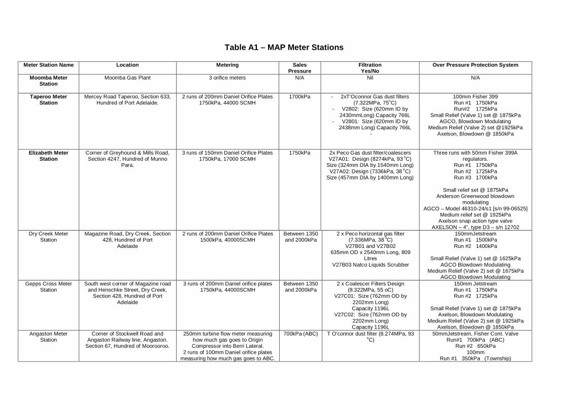
Table A1 – MAP Meter Stations
Meter Station Name Location Metering Sales Pressure
Filtration Yes/No
Over Pressure Protection System
Moomba Meter Station
Moomba Gas Plant 3 orifice meters N/A Nil N/A
Taperoo Meter Station
Mercey Road Taperoo, Section 633, Hundred of Port Adelaide.
2 runs of 200mm Daniel Orifice Plates 1750kPa, 44000 SCMH
1700kPa - 2xT’Oconnor Gas dust filters (7.322MPa, 75oC)
- V2802: Size (620mm ID by 2430mmLong) Capacity 766L
- V2801: Size (620mm ID by 2438mm Long) Capacity 766L
-
100mm Fisher 399 Run #1 1750kPa Run#2 1725kPa
Small Relief (Valve 1) set @ 1875kPa AGCO, Blowdown Modulating
Medium Relief (Valve 2) set @1925kPa Axelson, Blowdown @ 1850kPa
Elizabeth Meter Station
Corner of Greyhound & Mills Road, Section 4247, Hundred of Munno
Para.
3 runs of 150mm Daniel Orifice Plates 1750kPa, 17000 SCMH
1750kPa 2x Peco Gas dust filter/coalescers V27A01: Design (8274kPa, 93 oC)
Size (324mm DIA by 1540mm Long) V27A02: Design (7336kPa, 38 oC)
Size (457mm DIA by 1400mm Long)
Three runs with 50mm Fisher 399A regulators.
Run #1 1750kPa Run #2 1725kPa Run #3 1700kPa
Small relief set @ 1875kPa
Anderson Greenwood blowdown modulating
AGCO – Model 46310-24/s1 [s/n 99-06525] Medium relief set @ 1925kPa
Axelson snap action type valve AXELSON – 4”, type D3 – s/n 12702
Dry Creek Meter Station
Magazine Road, Dry Creek, Section 428, Hundred of Port
Adelaide
2 runs of 200mm Daniel Orifice Plates 1500kPa, 40000SCMH
Between 1350 and 2000kPa
2 x Peco horizontal gas filter (7.336MPa, 38 oC)
V27B01 and V27B02 635mm OD x 2540mm Long, 809
Litres V27B03 Natco Liquids Scrubber
150mmJetstream Run #1 1500kPa Run #2 1400kPa
Small Relief (Valve 1) set @ 1625kPa
AGCO Blowdown Modulating Medium Relief (Valve 2) set @ 1675kPa
AGCO Blowdown Modulating Gepps Cross Meter
Station South west corner of Magazine road
and Henschke Street, Dry Creek, Section 428, Hundred of Port
Adelaide
3 runs of 200mm Daniel orifice plates 1750kPa, 44000SCMH
Between 1350 and 2000kPa
2 x Coalescer Filters Design (8.322MPa, 55 oC)
V27C01: Size (762mm OD by 2202mm Long) Capacity 1196L
V27C02: Size (762mm OD by 2202mm Long) Capacity 1196L
150mm Jetstream Run #1 1750kPa Run #2 1725kPa
Small Relief (Valve 1) set @ 1875kPa
Axelson, Blowdown Modulating Medium Relief (Valve 2) set @ 1925kPa
Axelson, Blowdown @ 1850kPa Angaston Meter
Station Corner of Stockwell Road and
Angaston Railway line, Angaston. Section 67, Hundred of Moorooroo.
250mm turbine flow meter measuring how much gas goes to Origin Compressor into Berri Lateral.
2 runs of 100mm Daniel orifice plates measuring how much gas goes to ABC.
700kPa (ABC)
T O’connor dust filter (8.274MPa, 93
oC) 50mmJetstream, Fisher Cont. Valve
Run#1 700kPa (ABC) Run #2 650kPa
100mm Run #1 350kPa (Township)

American Meter Co. AL5000 displacement meter measuring how
much gas goes to the township
Run #2 330kPa (Township) Run #2 330kPa
No Regulation on Berri Lateral
Pt Pirie Meter Station Port Pirie Township Road, Port Pirie, Section 7017, Hundred of Port Pirie.
1 run with a 75mm Barton turbine meter 700kPa, 8000SCMH
Between 600-900kPa
Swinney Gas Filter Type A Peco Horizontal Dust Filter
V19PP01 V19PP02
50mm Jetstream/Fisher Run#1 700kPa Run #2 650kPa
(USI/D3 75x100mm) Bungama Scraper
Station Junction of Whyalla and Port Pirie
Laterals Nil To Port Pirie
3500kPa To Whyalla 6800kPa
Nil Approximately 3500kPa
Whyalla Township Meter Station
Inside BHP facility, near main entrance. Allotment 9, DP38820,
Hundred of Cultana
1 run, 100mm Email diaphragm American Meter Co. AL5000 Meter,
650kPa, 1550SCMH
Between 80 and 150kPa
Peco dust filter / Coalescer (7.336MPa, 38 oC)
V19W03: Size (508mm OD by 2450mm Long) Capacity 400L
25mm Tartarini Town Sales Monitor 175kPa
Active 150kPa Town Supply Monitor 680kPa
Active 640kPa Whyalla OneSteel
Meter Station Inside OneSteel facility, near main entrance. Allotment 9, DP38820,
Hundred of Cultana
1 run with a 300mm Rockwell Turbine Meter 650kPa, 30,000 SCMH
Between 650 and 850kPa
Peco dust filter / Coalescer (7.336MPa, 38 oC)
V19W03: Size (508mm OD by 2450mm Long) Capacity 400L
75mm Tartarini Run #1 Active 700kPa
Monitor 750kPa Run #2 Active 690kPa
Monitor 760kPa
Run #1 set @ 850kPa Run # 2 set @ 900kPa
Whyalla Cogen Meter Station
Inside OneSteel facility, near main entrance. Allotment 9, DP38820,
Hundred of Cultana
1 run with an 80mm Turbine Meter 1870kPa 2 x Dust filter / Coalescer (10.130MPa, 60 oC)
V19W03: Size (356mm OD by 2550mm Long) Capacity 220L
Run #1 Active 1880kPa Run #2 Active 1880kPa
Monitor 2000kPa
Set @ 2350kPa modulating Pacific Salt Meter
Station On the Whyalla lateral, adjacent to the Pacific Salt facility, Section 2,
Hundred of Cultana.
1 run with 100mm Email AL2300 Diaphragm Meter 350kPa, 156 SCMH
140kPa Gas Dust Filter (8.274MPa and 93
oC) V19P01: Size (220mm OD by 1650mm Long) Capacity 52L
25mm Tartarini Active: 490kPa Monitor: 520kPa
Small Relief Valve set @ 600kPa Port Bonython Meter
Station Near the main entrance of the Port
Bonython facility, Section 239, Hundred of Cultana.
150mm Rockwell Turbine Meter 1200kPa, 850 SCMH
637kPa Peerless Filter (8.224MPa, 93 oC) V19B01: Size (406mm OD by 1500mm Long) Capacity 140L
40mm Tartarini Active: 1080kPa Monitor: 1160kPa
Small Relief Valve set @ 1400kPa
Nuriootpa Meter Station
35km along the Angaston lateral 100mm Rockwell Turbine Meter (NB. Class #300)
1050kPa, 6500SCMH
Between 950 and 1150kPa
Natco Gas Filter (7.336MPa, 60 oC) Size (273mm OD by 1220mm Long)
Capacity 75L Natco Scrubber (1.379MPa, 38 oC
Size (618mm OD by 2286mm Long) Capacity 705L
50mmJetstream set @ 1050kPa
Small Relief Farris valve set @ 1200kPa (mod)
Freeling Meter Station Two kilometres south of Freeling on the Main Road, Section 395,
Hundred of Nuriootpa.
100mm diaphragm A.L. 5000 meter 320kPa, 1000SCMH
Between 250-420kPa
Nil 25mm Fisher 627 Active: 300kPa Monitor: 350kPa
Relief Valve set @ 400kpa

Modulating Fisher FS 1808-26, 1.5-2” N.P.T. steel body
type 3653 pilot. Burra Meter Station Samin Copper Works on the west
side of Burra, Linkson Street Burra
75mm Roots positive displacement meter 800kPa / 300kPa (2 stage
regulation), 1300SCMH
Between 70 and 300kPa
Gas Filter (7.336MPa, 60 oC) V23A01: Size (273mm OD by 1230mm Long) Capacity 70L
V23A02: Natco Scrubber (1.379MPa, 38 oC)
Size (324mm OD by 1626mm long) Capacity 125L
25mm Fisher Burra #1 set @700kPa Burra #2 set @ 250kPa
Burra #1 set @ 850kPa Burra #2 set @ 300 kPa
Hallett Meter Station Hallett Hill 1 Run with a G1000 Turbine Meter
4000kPa, 99376SCMH
1700kPa @ 28 oC
Coalescing Filter (9.8MPa, 60 oC, 5 micron)
Size (610mm OD by 2170mm Long) Capacity 570L
Gorter R100s-100-600 Monitor: 1650kPa Active: 1550kPa
Farris 27DA23M-20 set @ 10850kPa
Farris 26JA12-120 set @ 1950kPa (10% of Max Flow)
Peterborough Meter Station
Peterborough, Sales tap at KP 559.88 on MAP
75mm Roots Positive displacement meter
700kPa, 350SCMH
600kPa Natco Gas Filter and Natco Liquids Scrubber
V2001: Filter Size (273mm OD by 1220mm long) Capacity 67L
V2002: Scrubber, Size (273mm OD by 1220mm long) Capacity 100L
25mm Fisher Run #1 set @ 700kPa
Small Relief set @ 800kPa
AGCO, Blowdown Modulating
Cotton Road Meter Station
2km further down the Peterborough Lateral
Nil Between 300-400kPa
Nil 50mm Rockwell Run set @ 350kPa
Rockwell Valve #2 set @ 450kPa
Penfield Roses Meter Station
Short Road, Penfield, Allotment 9, DP 31457, hundred of Munno Para.
American Meter Co. AL5000 Displacement meter
Between 250-420kPa
Nil Active regulator set @ 300kPa Monitor set regulator set @ 350kPa
Relief Valve set @ 420kPa
Fisher FS98H-29 1” N.P.T. screwed, cast iron body S.S. trim, nitrile diaphragm
Virginia Meter Station Corner of Park & Supple Roads,
Virginia, Allotment 1, Section 7558, Hundred of Port Adelaide.
25mm diaphragm meter American Meter Co. AL5000 300kPa,
1000SCMH
Between 250 and 420kPa
Refer to P&ID 328-L-003 PASA built filter, 168mm OD x
1400mm long Capacity 36 litres, Design Pressure
7322kPa
Active set @ 300kPa Monitor set @ 350kPa
A fisher 399A-6365 relief valve is fitted in
the meter run set @ 400kPa Wasleys Metro Farm
Meter Station Within Metro Farm’s facility 5
kilometres North West of Wasleys, Section 89, Hundred of Grace.
America Meter Co. AL2300, is located in the second regulator diaphragm
100mm 1¼ ft^3 per rev
Between 250-420kPa
Nil Fisher 627M Upstream Active set @ 360kPa
Downstream Monitor set @ 340kPa
Farris 26FC10-120 1.5” Downstream of the regulators set @
400kPa Wasleys Compressor
and Meter Station The beginning of the Wasleys
Loopline where KP 731.9 2 Orifice Meters 5100kPa Nil Active set @ 6100kPa
Monitor set @ 6400kPa She-Oak Log
Regulator Station The Meter station Lauke’s Feed mill
facility, Daveyston. Section 100, Hundred of Nuriootpa
Nil between 250 and 420kPa
Nil Fisher 627 14,000kPa390 SCMH U/S active set @ 360kPa
D/S monitor set @ 340kPa

Symes Road Meter Station
Corner of Syme’s and Coleman Roads, St Kilda.
Roots Turbine Flow Meter 350kPa Nil Active: 300kPa Monitor: 350kPa
Vent set @ 400kPa
Mintaro Meter Station The Mintaro Lateral is a 200mm off take from the MAP at a KP of 665.19 the Mintaro lateral travels for some 330m to the Mintaro Meter Station.
Nil 1800kPa 2 x Gas Filters (7870kPa, 10 to 40
oC) V2401 and V2402
Size (400mm OD by 2200mm) Capacity 277L
Run #1 set @ 1900kPa Run #2 set @ 1850kPa
Run #1 set @ 2090kPa Run #2 set @ 2090kPa
Amcor Meter Station Argent Road, Concordia.
Nil 250kPa F-001 Coalescing Filter (9930kPa, 60
oC, 10 micron) set @ 1100kPa set @ 850kPa
set @ 1400kPa set @ 1100kPa
Pelican Point Meter & Regulator Station
On Pelican Point Lateral inside Power Station compound.
3 Turbine Meters 2765kPa 2X Filter Coalescers (10204kPa, 0-37 oC)
V2004, V2010: Size (749mm ID by 2363mm Long)
TK 2020 1000L above ground liquids tank.
Active set @ 2700kPa Run#1 Monitor set @ 2850kPa Run#2 Monitor set @ 2925kPa Run#3 Monitor set @3000kPa
Origin / Quarantine Meter Station
The Origin lateral is an off-take from Wasley’s loop, the meter station is
located inside the power station compound on Torrens Island.
1 Turbine Meter, Model No. G650 2900kPa, 30,337SCMH
2375kPa @ 27 oC
Coalescing Filter (9800kPa, 60 oC) F101: 2800kPa, 301 24SCMH
Active set @ 2390kPa Monitor set @ 2440kPa
set @ 3000kPa
Torrens Island Meter Station
Behind the Torrens Island Power Station which is located at the end of the Moomba to Adelaide pipeline and
end of Wasleys loop.
3 Runs of 300mm Daniel Orifice 1800kPa 3x Filter/Coalescers (8322kPa, 55 oC) V 3001, V 3002: Size (762mm OD by
2253mm Long) 1196L V 3003: Size (1372mm OD by
3176mm Long) 4922L
150mm Jetstreams, also 1 regulator by-pass run.
Run#1 1825kPa Run#2 1800kPa Run#3 1775kPa Run#4 1750kPa
Run#1 Small 3”x4” Axelson set @
1950kPa Run#2 Large 8”x10” Anderson Greenwood
set @2100
Osborne Meter Station & Regulator
Station
Mercey Rd. Osborne. 2 x Turbine Meters 2490kPa Filter/Coalescer (7322kPa, 50 oC) V 2901: (Size 750mm OD by
2551mm Long) V 2902: (Size 350mm OD by
1800mm Long)
MS: set @ 2400kPa RS: set @ 2700kPa (Active)
set @ 2900kPa (Monitor) set @ 2700kPa (By-pass)
Frost Road Frost Road Hundred of Port Gawler
Two Wells
Coriolis Mass Flow Meter FE-101
450kpa Y Strainer SP-100
Active regulator set @ 450kpa Monitor regulator set @ 475kpa Relief valve set point @ 550kpa
ESD valve set to close @ 550koa
A.2 COMPRESSOR STATIONS Epic Energy operates four compressor stations on the Moomba to Adelaide pipeline being stations 1, 3, 4 and 6 with Stations 2, 5 and 7 decommissioned in 2006. The pipe work at the decommissioned compressor stations has been disconnected from the main line, blinded and vented of all gas. A new cathodic protection unit has been installed to allow individual CP outputs to be applied to each decommissioned sites underground pipe work and the pipeline in the immediate area. The turbine packages have been isolated and chemically preserved on site, Fire and gas systems have been isolated and the fire suppressant material (NAF-S-III gas) removed. All stores, bulk oils and fuel has been removed, service buildings have been locked and no longer available for use. The station inlet suction and outlet discharge valve power operators have been completely disabled and the station pressurizing skid has been isolated by removing pipe spools which removes all turbine and GEA fuel and associated control gases from the sites. The 24 volt DC batteries have been isolated and removed from sites. The GEA’s remain operational at CS2 to supply the Moomba – Adelaide pipeline cathodic protection system. The GEA’s at CS5 & 7 have been decommissioned and isolated from the electrical distribution system as well as their fuel gas supplies. In 1998, the MAP Compressor Stations underwent a major upgrade of their compression equipment. This included the replacement of the Solar Centaur T4002 3850HP packages at stations 1, 2, 3, 5 & 6 with Solar Taurus T60 6500HP packages and the upgrade of the Ingersoll Rand GT-22 packages at CS2 and 4 from a horsepower capacity of 4,250 to 5,400. At the same time the station control system was upgraded from an antiquated electro–mechanical system to an Allen Bradley PLC5 system. The pipeline was further enhanced in 2000 by the construction of 34kms of 24” loops south of stations 1, 2, 3 & 4 and the remaining 4 Ingersol Rand packages being upgraded to the Allison 501-KC5 specification with a power rating of 5250 horsepower. A further major undertaking in 2000 was the installation of a reciprocating compressor at Wasleys with an installed power rating of 2200HP. Compressor Stations 1-7 consist of typically a MLV and Scraper Station facility, Station Suction and Discharge valve assemblies with the components downstream of these valves arranged as follows: • Main Station pipe work consisting of 550mm NB. • A Centrifugal Gas Scrubber Assembly. • A Suction Header incorporating two John’s 550mm Check Valves. • Valving from this Suction Header routes gas through two centrifugal process gas
compressors powered by a gas turbine driver with the compressors configured in series. • The process compressors discharge is connected to the discharge header which passes
the gas through an after cooler assembly to remove excess heat from the compressed gas.
• A metering run consisting of an orifice plate, pressure and temperature measurement and a ∆P transmitter to measure the gas flow through the station.
• A Station Vent Valve Assembly for over pressure protection and to provide an ESD facility.
• Pressure reduction equipment is connected to the main station pipe work to produce turbine and gas engine alternator (GEA) fuel and control gas supplies at the pressures required for each of these functions.
• Incorporated within the Station compound are a services building housing the Control Room, Battery Room, Workshop and Store facility and a power house typically consisting of three GEA’s.
Details of each compressor station are given below: A.2.1 COMPRESSOR STATIONS 1 TO 3 Unit A: Solar Taurus T60 package comprising Solar Taurus 60.gas turbine engine and a Solar C402.centrifugal compressor. Upgrade commissioned in 1998. Unit B: Ingersoll Rand GT-22 package comprising an Allison 501-KC5 gas turbine and a Dresser Rand CDP 416 centrifugal compressor. Upgrade commissioned in 2000 Compressor station controls are provided by an Allen–Bradley PLC housed in the Station Control Room. This PLC interfaces between TSCC via SCADA and the on-site HMI and processes all station and unit controls including set point changes for process control. The power generation capability at these sites consists of three gas driven engine alternator sets of a nominal capacity of 90 kW. GEA’s 1 & 2 are Caterpillar 68D driven machines direct coupled to a Stamford 415V 3 phase alternator. GEA 3 is a Caterpillar 7Y machine direct coupled to a Caterpillar 415V 3 phase alternator. All of these machines are capable of stand-alone operation or can be parallelled to each other to give a total nominal capacity of 270 kW. These machines are controlled by an intelligent engine management control system. A.2.2 COMPRESSOR STATION 4 Unit A: Ingersoll Rand GT-22 package comprising an Allison 501-KC5 gas turbine and a Dresser Rand CDP 416 centrifugal compressor. Upgrade commissioned in 1998 Unit B: Ingersoll Rand GT-22 package comprising an Allison 501-KC5 gas turbine and a Dresser Rand CDP 416 centrifugal compressor. Upgrade commissioned in 1998 Compressor station controls are provided by an Allen–Bradley PLC housed in the Station Control Room. This PLC interfaces between TSCC via SCADA and the on-site HMI and processes all station and unit controls including set point changes for process control. The power generation capability at this site consists of three gas driven engine alternator sets. GEA 1 & 2 each has a nominal capacity of 90 kW while GEA 3 is nominally rated at180 kW. GEA’s 1 & 2 are Waukesha F817 gas engines direct coupled to a Dunlite alternator. GEA 3 is a Waukesha H2475 gas engine direct coupled to a Stamford alternator. All of these machines are capable of stand-alone operation or can be parallelled to each other to give a total capacity of a nominal 360 kW. These machines are controlled by an intelligent engine management control system. A2.3 COMPRESSOR STATION 6 Unit A: Solar Taurus T60 package comprising Solar Taurus 60.gas turbine engine and a Solar C402.centrifugal compressor. Upgrade commissioned in 1998. Unit B: Ingersoll Rand GT-22 package comprising an Allison 501-KC5 gas turbine and a Dresser Rand CDP 416 centrifugal compressor. Upgrade commissioned in 2000. Compressor station controls are provided by an Allen–Bradley PLC housed in the Station Control Room. This PLC interfaces between TSCC via SCADA and the on-site HMI and processes all station and unit controls including set point changes for process control. Power generation at this site consists of two GEA’s with nominal capacities of 9- & 125kW: GEA 1 is a Caterpillar 68D driven machine direct coupled to a Caterpillar 415V 3 phase alternator. The
controls for this machine are handled by an electro-mechanical control system. GEA 2 is a Caterpillar G3406 engine alternator set in an acoustic canopy and is a stand-alone unit. These sets cannot be run in parallel. These machines act in a duty stand-by arrangement when the turbine units are operating and can back up the mains SWER line from the S.A power grid. A.2.4 WHYTE YARCOWIE COMPRESSOR STATION This station consists of a MLV and Scraper Station facility, inlet suction and outlet discharge valves feeding suction and discharge headers. Components downstream of these valves are arranged as follows: • Main Station pipe work consisting of 150mm NB line pipe. • Valving from the Suction Header routes gas through a reciprocating compressor package
with the discharge gas passing through an after cooler assembly, to remove excess heat from the compressed gas before passing back into the discharge header.
• There is a hydrocarbon waste collector tank which collects hydrocarbons from the package suction and discharge line automatically drained scrubber vessels.
• A metering run measures the gas flow through the station. • A Station Vent Valve Assembly for the over pressure protection and to provide an ESD
facility. • Pressure reduction equipment is connected to the main station pipework to provide fuel
and control gas supplies at the pressures required for the reciprocating compressor unit station powered valves.
Incorporated within the Station compound are a services building housing the Control Room, Battery Room, Workshop and Store facility. A.2.5 WASLEYS COMPRESSOR STATION The Wasleys Compressor Station consists of a MLV, Scraper Station facility and boost compressor for the Wasleys to Torrens Island 500mm NB loop-line, primarily supplying the Pelican Point Power Station. Compressor capacity control is accomplished by varying engine speed, compressor cylinder loaders and the unit recycle valve position. A station fire and gas detection system is installed. The compressor unit discharge flows through the station after-cooler assembly, to remove heat from the compressed gas. The discharge gas flow is metered using an orifice metering run. Unit fuel gas is metered using a coriolis meter. A hydrocarbon waste collection tank is installed to collect hydrocarbons from the coalescer assemblies installed on the unit suction and discharge headers. A unit vent valve assembly is installed for the provision of purging and ESD facility. Ancillary equipment such as fuel/start gas and lube oil makeup systems are also installed. Incorporated within the station compound is a services building that houses the control room, battery room and lunchroom facilities. A separate workshop and store facility is also provided. The station consists of Caterpillar G3680TAW turbo charged gas engine and a Aerial JGC/4 reciprocating compressor.
A.3 PIG LAUNCHERS AND RECEIVERS Pig launcher/receiver assemblies are located at all Compressor Station sites, spaced approx 100 kilometres on the mainline. Starting at CS1, 2, 3 & 4 the pipeline has been looped for several kilometres downstream and these 24” looping section can be pigged using portable pig launcher and receiver assemblies that need to be shifted from site to site. Laterals with pigging facilities include, Whyalla lateral, Port Pirie lateral, Wasleys loop line,
Angaston lateral and the Pelican Point lateral. In general both the Launcher and Receiver are equipped with a quick opening, horizontally hinged, Unibolt Closure equipped with safety interlock. All Launcher/Receiver assemblies are equipped with kicker lines complete with associated valving to enable cleaning and intelligent tool pigging operations and to ensure pipeline flow can be accommodated through these lines without significantly causing any throttling effect on pipeline operations. Launchers and Receivers are isolated from the Mainline via W.K.M. “Saf-T-Seal” round body, through conduit, gate valves. A.4 SCRUBBERS Centrifugal gas scrubbers are installed at Compressor Stations 1, 3, 4 and 6. Gas enters the tube bundle tangentially, creating a high centrifugal force that projects solids and liquids to the walls of the tubes, allowing clean gas to pass through the scrubber and waste impurities to be collected in the Dust Collector vessel, located below the scrubber. The Station PLC cycles the Scrubber valves automatically twice every 24 hours, to eject the contents of the dust collector into the below ground scrubber tank. A.5 AFTER COOLERS Process gas cooling facilities are operational at Compressor Stations 1, 3, 4 and 6 on the Moomba – Adelaide Pipeline. Cooling of the gas after compression is achieved by a fin fan cooler system which utilizes two tube bundles and two electrically driven 4.88 metre diameter fans. Process gas cooling facilities are also installed at Angaston, Whyte Yarcowie and the Wasleys reciprocating compressor stations with the fan drivers being provided by the reciprocating engine or compressor to ensure the process gas temperature remains within the pipeline design. A.6 MAIN LINE VALVES There are 30 Main Line valves on the MAP installed approximately 32km apart. Of these, 14 are actuated valves and are capable of remote operation. There are a further 16 non-actuated valves equipped with manual operators. Additional mainline valves are located on other laterals and piping associated with Pipeline Licence 1 includes:
• Wasleys to Torrens Island Loop Line 7 • Port Pirie Lateral 4 • Burra Lateral 2 • Peterborough Lateral 2 • Whyalla Lateral 4 • Angaston Lateral 3 • Pelican Point Lateral 2 • Osborne Lateral 2 • Dry Creek Lateral 2 • Taperoo Lateral 2 • Port Bonython Lateral 2 • Nuriootpa Lateral 2
A.6.1 VALVES GENERAL All mainline valves are 550mm Cameron Full Bore Ball Valves and are installed below ground, with the exception of MLV4, located at Compressor Station 1, which is a 400mm Grove Full Bore Ball Valve. Each MLV has s a 150mm NB by-pass line equipped with two 150mm NB Ball Valves. The Wasleys loop line valves are 500mm Cameron full bore ball valves and are installed below ground. The valves connecting the loop line to the mainline are 500mm Cameron reduced bore ball valves. A.6.2 ACTUATED VALVES On the mainline there are 14 of these valves between Moomba and Torrens Island. These valves are equipped with pneumatic–hydraulic rotary, vane type Shafer operators. These actuators are powered by natural gas, extracted from the mainline and regulated to a pressure suitable for this purpose. These valves are required to be remotely operated from Epic Energy’s TSCC as they have no automatically line break facilities. Six of the loop line valves are also power actuated using pneumatic rotary type Rotork actuators and are controlled via SCADA. A.6.3 NON ACTUATED VALVES All valves are 550mm Cameron Full Bore Ball Valves and are installed below ground, with the exception of MLV4, located at Compressor Station 1, which is a 400mm Grove Full Bore Ball valve. These valves are equipped with an operator and gearbox assembly, to allow the valves to be operated manually. Incorporated into the MLV pipe work, is a 150mm NB by-pass line equipped with two 150mm NB Ball Valves. At compressor stations 1, 2, 3 & 4 the pipeline has been looped and these loops have 600mm manually operated Perar valves installed to allow the section. The connections between the 550mm mainline and the 600mm loop are via 500mm Perar manually operated ball valves A.7 FILTRATION
All major gas delivery points have upstream dry dust filters and downstream coalescing filtration. The dust filters have onsite differential pressure gauges and contain a mixture of Pall and Pearless type filter elements. The separator units have high level alarms to TSCC via the Valmet system and all units contain Pall coalescer type elements. A.8 ROW For the Moomba to Adelaide Pipeline, access to compressor stations and pipeline south of Compressor Station 6, is by public roads. Access to pipeline north of Compressor Station 6 is generally via the Right of Way which is a well formed gravel road within the pipeline easement corridor running from CS6 to the intersection of the Strzelecki Track, just north of CS2. North of this point to Moomba, the ROW contains an access track of variable condition. Vehicle access between CS6 and CS5 is barred to through traffic by locked gates. Access between these points is only permitted to the affected Pastoral Lessees or authorised Epic contractors or employees that have work duties within this area. Through traffic has been banned as a measure to control the spread of a weed that is prevalent in this area. Access to CS 5 is obtained by the Orroroo to Barrata homestead mail road, which intersects the Right of Way approximately 1km south of the Station. The Strzelecki Track is used as access to facilities at CS1 and Moomba. A well formed gravel
road, approximately 10km in length, maintained by Epic, connects CS1 to the Strzelecki Track. For facilities such as communication towers and CP, access is generally via tracks across pastoral leases or private land. Access to these tracks is generally covered in the leases or easements agreements which allow access rights to maintain and repair facilities. Access tracks are gated and secured by lock and chain. Maintenance of access roads has generally been confined to the repair of water erosion damage, following periods of unusually heavy rainfall. A.9 SWER LINES A.9.1 MOOMBA TO COMPRESSOR STATION 1 Santos (at Moomba) operates a Three Phase, 11kV Power Line from their ‘South Central’ feeder ring main which feeds a 19KV SWER line to KP 62 on the MAP. Step down Transformers are installed on the SWER Line to supply power for the Cathodic Protection TRU located on the Gas and Liquids Pipelines. In 1997, the original SWER from Santos was extended to KP 62.0. This extension powers additional Cathodic Protection TRU sites on the pipeline and is owned and operated by Epic Energy. A.9.2 COMPRESSOR STATION 1 - SOUTH TO KP 116.6 Epic Energy owns and operates a SWER from Compressor Station 1 to KP116.6. This SWER is powered by the GEA’s at CS1 and is supplied from a 10 KVA, 415 V to 19 kV step-up transformers. This SWER line services 9 Cathodic Protection TRU sites and 1 Communications Site. A.9.3 COMPRESSOR STATION 2 - SOUTH TO KP 290.1 In 1996, Hawker Council constructed the 19kv SWER line from CS2 South. This 47.7-km line is powered by the GEA’s at CS2 and provides power for a Radio Communications Facility (KP 209), owned by Santos and operated by Epic Energy together with 11 Cathodic Protection TRU units. A.9.4 COMPRESSOR STATION 5 – NORTH TO KP 402.6 Epic’s “CS5” SWER line draws power from ETSA’s Yalpara SWER line which operates at 19kV. The SWER line runs from KP 524 to KP 386.3 a distance of 138.2km. The SWER line powers 3 radio communications facilities and 17 cathodic protection installations. A.10 COMMUNICATIONS SYSTEMS Communication links between the compressor stations, meter stations and MLV RTU’s with TSCC consist of Epic Energy owned and leased infrastructure, as well as Santos owned infrastructure. The Epic Energy owned infrastructure consists of Microwave Data Systems digital microwave bearer and RAD multiplexer. The infrastructure originates at Peterborough and terminates at compressor station 4. The bearer and it’s associated multiplexer provide the backbone of the transmission path. Epic Energy utilises the Santos infrastructure to communicate from compressor station 4, north to Moomba. This consists of an NEC microwave bearer and Nokia multiplexer. The infrastructure originates at Port Bonython and terminates at Moomba. The bearer and it’s associated multiplexer provide the backbone of the transmission path.
The Epic Energy owned or leased infrastructure, provide the transmission path from Peterborough to Adelaide and also from Port Bonython to Adelaide then through to TSCC in Melbourne. The leased infrastructure consists of Telstra frame relay services. Epic Energy owns the Cisco routers, which provide the SCADA path to Adelaide and Melbourne.. A number of communications services have been purchased from major telecommunication vendor Telstra to transmit data to TSCC and control instructions from TSCC to the field. DDS, PAPL (Leased Lines), PSTN (Dialup) and Frame Relay are the communication services provided by Telstra and utilised by Epic. These products provide communication from Meter Stations, Valve Sites, Radio and Epic Energy owned communication infrastructure to TSCC via a leased Virtual Private Network. Trials are currently underway to evaluate Next-G Mobile services and IP-Telemetry Services provided by Telstra to replace DDS and PAPL Services which will be discontinued by 2008 and 2009 respectively. A.11 PIPELINE MONITORING SYSTEMS Epic Energy operates and controls the Moomba to Adelaide Pipeline from the Transportation Services Control Centre (TSCC) in Melbourne, Victoria, using the Telvent SCADA System. The Moomba to Adelaide Pipeline can also be monitored and controlled from Epic Energy’s emergency recovery control centre at Hansens, Doncaster, Victoria. The Epic Energy SCADA system is a distributed, dual redundant, SCADA system which utilises Epic Energy and third party communications providers to communicate to the remote field telemetry devices. A volume based Pipeline Leak Monitoring system is configured in the SCADA system to alarm when a defined volume imbalance is experienced in a defined period of time. The SCADA system is well supported technically by a services level agreement with TUSC in Melbourne and Telvent in Canada who provide regular services. Epic in 2007 have perform a major SCADA upgrade with TUSC and Telvent to replace the current Unix platform Telvent 5.2.2 OASyS SCADA system with the Windows platform Telvent DNA7.4
APPENDIX 2 SAFETY POLICY
APPENDIX 3 ENVIRONMENTAL POLICY
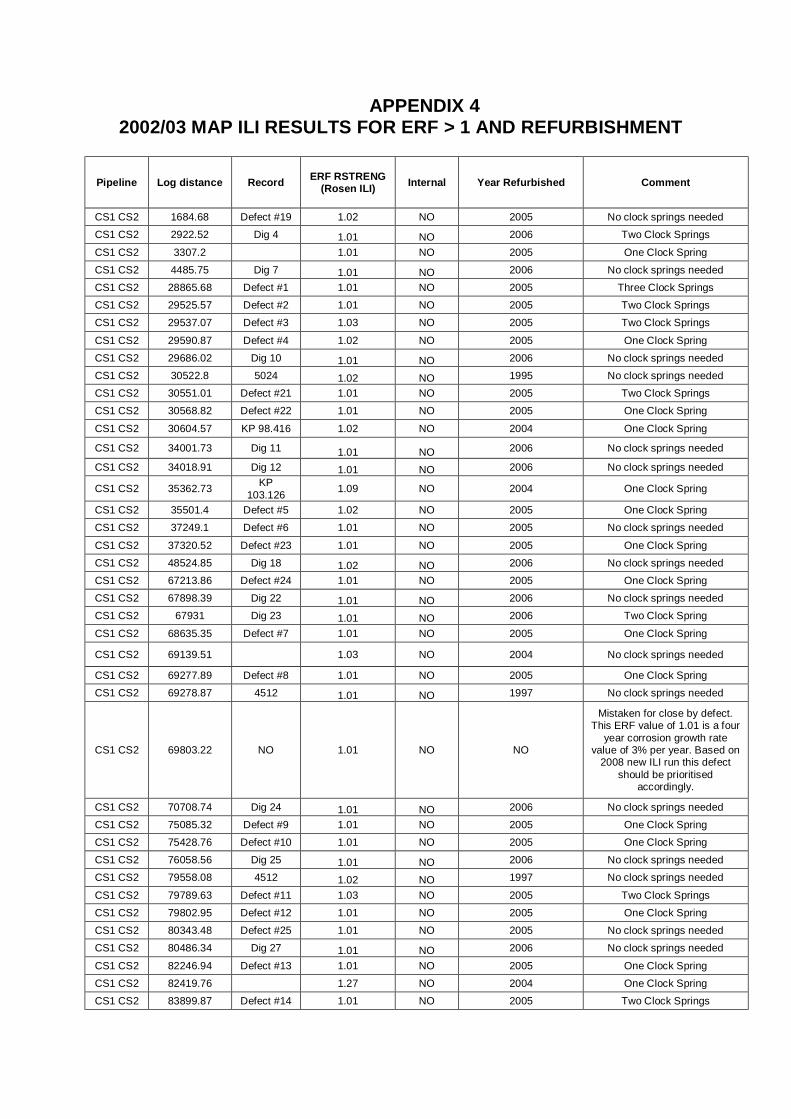
APPENDIX 4 2002/03 MAP ILI RESULTS FOR ERF > 1 AND REFURBISHMENT
Pipeline Log distance Record ERF RSTRENG (Rosen ILI) Internal Year Refurbished Comment
CS1 CS2 1684.68 Defect #19 1.02 NO 2005 No clock springs needed
CS1 CS2 2922.52 Dig 4 1.01 NO 2006 Two Clock Springs
CS1 CS2 3307.2 1.01 NO 2005 One Clock Spring
CS1 CS2 4485.75 Dig 7 1.01 NO 2006 No clock springs needed
CS1 CS2 28865.68 Defect #1 1.01 NO 2005 Three Clock Springs
CS1 CS2 29525.57 Defect #2 1.01 NO 2005 Two Clock Springs
CS1 CS2 29537.07 Defect #3 1.03 NO 2005 Two Clock Springs
CS1 CS2 29590.87 Defect #4 1.02 NO 2005 One Clock Spring
CS1 CS2 29686.02 Dig 10 1.01 NO 2006 No clock springs needed
CS1 CS2 30522.8 5024 1.02 NO 1995 No clock springs needed
CS1 CS2 30551.01 Defect #21 1.01 NO 2005 Two Clock Springs
CS1 CS2 30568.82 Defect #22 1.01 NO 2005 One Clock Spring
CS1 CS2 30604.57 KP 98.416 1.02 NO 2004 One Clock Spring
CS1 CS2 34001.73 Dig 11 1.01 NO 2006 No clock springs needed
CS1 CS2 34018.91 Dig 12 1.01 NO 2006 No clock springs needed
CS1 CS2 35362.73 KP 103.126 1.09 NO 2004 One Clock Spring
CS1 CS2 35501.4 Defect #5 1.02 NO 2005 One Clock Spring
CS1 CS2 37249.1 Defect #6 1.01 NO 2005 No clock springs needed
CS1 CS2 37320.52 Defect #23 1.01 NO 2005 One Clock Spring
CS1 CS2 48524.85 Dig 18 1.02 NO 2006 No clock springs needed
CS1 CS2 67213.86 Defect #24 1.01 NO 2005 One Clock Spring
CS1 CS2 67898.39 Dig 22 1.01 NO 2006 No clock springs needed
CS1 CS2 67931 Dig 23 1.01 NO 2006 Two Clock Spring
CS1 CS2 68635.35 Defect #7 1.01 NO 2005 One Clock Spring
CS1 CS2 69139.51 1.03 NO 2004 No clock springs needed
CS1 CS2 69277.89 Defect #8 1.01 NO 2005 One Clock Spring
CS1 CS2 69278.87 4512 1.01 NO 1997 No clock springs needed
CS1 CS2 69803.22 NO 1.01 NO NO
Mistaken for close by defect. This ERF value of 1.01 is a four
year corrosion growth rate value of 3% per year. Based on
2008 new ILI run this defect should be prioritised
accordingly.
CS1 CS2 70708.74 Dig 24 1.01 NO 2006 No clock springs needed
CS1 CS2 75085.32 Defect #9 1.01 NO 2005 One Clock Spring
CS1 CS2 75428.76 Defect #10 1.01 NO 2005 One Clock Spring
CS1 CS2 76058.56 Dig 25 1.01 NO 2006 No clock springs needed
CS1 CS2 79558.08 4512 1.02 NO 1997 No clock springs needed
CS1 CS2 79789.63 Defect #11 1.03 NO 2005 Two Clock Springs
CS1 CS2 79802.95 Defect #12 1.01 NO 2005 One Clock Spring
CS1 CS2 80343.48 Defect #25 1.01 NO 2005 No clock springs needed
CS1 CS2 80486.34 Dig 27 1.01 NO 2006 No clock springs needed
CS1 CS2 82246.94 Defect #13 1.01 NO 2005 One Clock Spring
CS1 CS2 82419.76 1.27 NO 2004 One Clock Spring
CS1 CS2 83899.87 Defect #14 1.01 NO 2005 Two Clock Springs
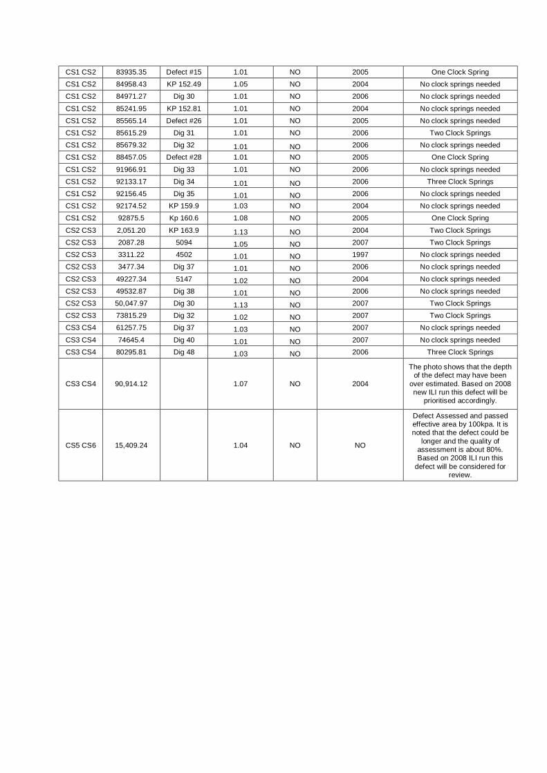
CS1 CS2 83935.35 Defect #15 1.01 NO 2005 One Clock Spring
CS1 CS2 84958.43 KP 152.49 1.05 NO 2004 No clock springs needed
CS1 CS2 84971.27 Dig 30 1.01 NO 2006 No clock springs needed
CS1 CS2 85241.95 KP 152.81 1.01 NO 2004 No clock springs needed
CS1 CS2 85565.14 Defect #26 1.01 NO 2005 No clock springs needed
CS1 CS2 85615.29 Dig 31 1.01 NO 2006 Two Clock Springs
CS1 CS2 85679.32 Dig 32 1.01 NO 2006 No clock springs needed
CS1 CS2 88457.05 Defect #28 1.01 NO 2005 One Clock Spring
CS1 CS2 91966.91 Dig 33 1.01 NO 2006 No clock springs needed
CS1 CS2 92133.17 Dig 34 1.01 NO 2006 Three Clock Springs
CS1 CS2 92156.45 Dig 35 1.01 NO 2006 No clock springs needed
CS1 CS2 92174.52 KP 159.9 1.03 NO 2004 No clock springs needed
CS1 CS2 92875.5 Kp 160.6 1.08 NO 2005 One Clock Spring
CS2 CS3 2,051.20 KP 163.9 1.13 NO 2004 Two Clock Springs
CS2 CS3 2087.28 5094 1.05 NO 2007 Two Clock Springs
CS2 CS3 3311.22 4502 1.01 NO 1997 No clock springs needed
CS2 CS3 3477.34 Dig 37 1.01 NO 2006 No clock springs needed
CS2 CS3 49227.34 5147 1.02 NO 2004 No clock springs needed
CS2 CS3 49532.87 Dig 38 1.01 NO 2006 No clock springs needed
CS2 CS3 50,047.97 Dig 30 1.13 NO 2007 Two Clock Springs
CS2 CS3 73815.29 Dig 32 1.02 NO 2007 Two Clock Springs
CS3 CS4 61257.75 Dig 37 1.03 NO 2007 No clock springs needed
CS3 CS4 74645.4 Dig 40 1.01 NO 2007 No clock springs needed
CS3 CS4 80295.81 Dig 48 1.03 NO 2006 Three Clock Springs
CS3 CS4 90,914.12 1.07 NO 2004
The photo shows that the depth of the defect may have been
over estimated. Based on 2008 new ILI run this defect will be
prioritised accordingly.
CS5 CS6 15,409.24 1.04 NO NO
Defect Assessed and passed effective area by 100kpa. It is noted that the defect could be
longer and the quality of assessment is about 80%. Based on 2008 ILI run this
defect will be considered for review.
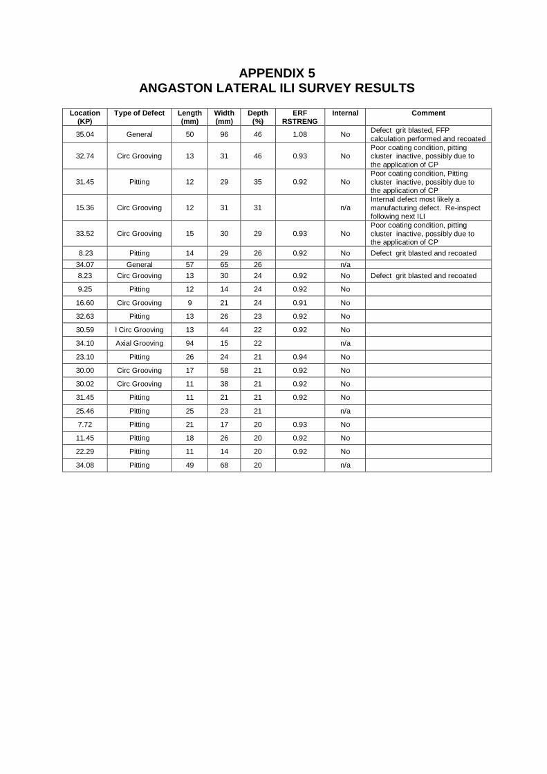
APPENDIX 5 ANGASTON LATERAL ILI SURVEY RESULTS
Location
(KP) Type of Defect Length
(mm) Width (mm)
Depth (%)
ERF RSTRENG
Internal Comment
35.04 General 50 96 46 1.08 No Defect grit blasted, FFP calculation performed and recoated
32.74 Circ Grooving 13 31 46 0.93 No Poor coating condition, pitting cluster inactive, possibly due to the application of CP
31.45 Pitting 12 29 35 0.92 No Poor coating condition, Pitting cluster inactive, possibly due to the application of CP
15.36 Circ Grooving 12 31 31 n/a Internal defect most likely a manufacturing defect. Re-inspect following next ILI
33.52 Circ Grooving 15 30 29 0.93 No Poor coating condition, pitting cluster inactive, possibly due to the application of CP
8.23 Pitting 14 29 26 0.92 No Defect grit blasted and recoated 34.07 General 57 65 26 n/a 8.23 Circ Grooving 13 30 24 0.92 No Defect grit blasted and recoated
9.25 Pitting 12 14 24 0.92 No
16.60 Circ Grooving 9 21 24 0.91 No
32.63 Pitting 13 26 23 0.92 No
30.59 l Circ Grooving 13 44 22 0.92 No
34.10 Axial Grooving 94 15 22 n/a
23.10 Pitting 26 24 21 0.94 No
30.00 Circ Grooving 17 58 21 0.92 No
30.02 Circ Grooving 11 38 21 0.92 No
31.45 Pitting 11 21 21 0.92 No
25.46 Pitting 25 23 21 n/a 7.72 Pitting 21 17 20 0.93 No 11.45 Pitting 18 26 20 0.92 No 22.29 Pitting 11 14 20 0.92 No 34.08 Pitting 49 68 20 n/a
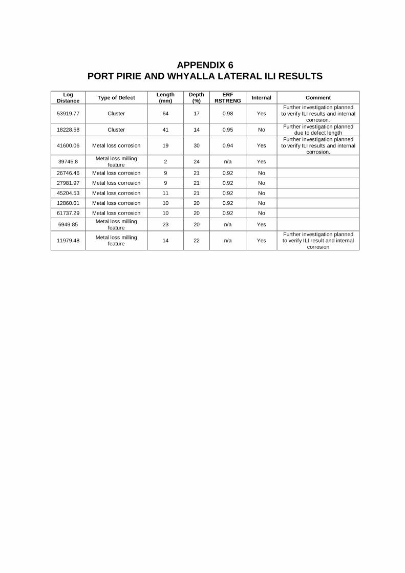
APPENDIX 6
PORT PIRIE AND WHYALLA LATERAL ILI RESULTS
Log Distance Type of Defect Length
(mm) Depth
(%) ERF
RSTRENG Internal Comment
53919.77 Cluster 64 17 0.98 Yes Further investigation planned
to verify ILI results and internal corrosion.
18228.58 Cluster 41 14 0.95 No Further investigation planned due to defect length
41600.06 Metal loss corrosion 19 30 0.94 Yes Further investigation planned
to verify ILI results and internal corrosion.
39745.8 Metal loss milling feature 2 24 n/a Yes
26746.46 Metal loss corrosion 9 21 0.92 No
27981.97 Metal loss corrosion 9 21 0.92 No
45204.53 Metal loss corrosion 11 21 0.92 No
12860.01 Metal loss corrosion 10 20 0.92 No
61737.29 Metal loss corrosion 10 20 0.92 No
6949.85 Metal loss milling feature 23 20 n/a Yes
11979.48 Metal loss milling feature 14 22 n/a Yes
Further investigation planned to verify ILI result and internal
corrosion

APPENDIX 7 DCVG SURVEY RESULT
Survey Date Pipeline Location ( KP) %IR Remarks
2002 Burra Lateral 7.853 22 April 03, coating repair only, no SCC 2002 Peterborough Lateral 0.599 16 April 03, coating repair only, no SCC 2002 Port Bonython Lateral 4.625 14 April 03, Southern Cross Off take Valve 2002 Port Pirie Lateral 52.424 46 April 03, coating repair only, no SCC 2002 Port Pirie Lateral 72.798 46 2002 Whyalla Lateral 41.2 56 April Valve No 2 supports repainted 2002 Whyalla Lateral 70.955 44 April 03, coating repair only, no SCC 2002 Whyalla Lateral 0.009 58 April 03, coating repair only, no SCC
June 2003 Wasleys to TI 0.12 21 July 03 Anchor Block June 2003 Wasleys to TI 750.002 40 April 04 coating blistered, stripped, blasted
and recoated June 2003 Wasleys to TI 750.052 29 April 04, Anchor Block June 2003 Wasleys to TI 764.349 16 Resurvey 2008 planned to validate results June 2003 Wasleys to TI 764.530 19 Resurvey 2008 planned to validate results June 2003 Wasleys to TI 27 Resurvey 2008 planned to validate results June 2003 Wasleys to TI 21 Resurvey 2008 planned to validate results June 2003 Wasleys to TI 773.004 30 Resurvey 2008 planned to validate results June 2003 Dry Creek Lateral 20 Resurvey 2008 planned to validate results June 2003 Taperoo Lateral 0.218 42 Resurvey 2008 planned to validate results June 2003 Taperoo Lateral 0.227 35 Resurvey 2008 planned to validate results June 2003 Taperoo Lateral 0.856 15 Resurvey 2008 planned to validate results
2004 Moomba Plant to KP 30 D/S Moomba Total survey distance 30 km 2004 CS1 to Kp 97.9 D/S CS1 Total survey distance 30 km 2004 CS2 to Kp 191.3 D/S CS2 Total survey distance 30 km 2004 CS3 to Kp 263.9, Kp 280 to Kp 286.3 D/S CS3 Total survey distance 22.4 km 2004 CS4 to Kp 382.8 D/S CS4 Total survey distance 30 km 2004 CS5 to Kp 463.6, 464.9 to 469.7,
471.3 to 474.5. D/S CS5 Total survey distance approx 26.8 km
2004 CS6 from Kp 542.9 to Kp 565.4 D/S CS6 Total survey distance 22.5 km 2004 CS7 Kp 648.2 to Kp 668.4 D/S CS7 Total survey distance 20.2 km 2007 Whyalla & Pt Pirie Laterals 24 defects > 15 Engineering Review to occur and assess 2007 Angaston Lateral 168 defects > 15 Engineering Review to occur and assess 2007 Burra Lateral 1 defect > 15 Engineering Review to occur and assess 2007 CS3 Loop 0 defects > 15 Engineering Review to occur and assess 2007 Peterborough Lateral 2 defects > 15 Engineering Review to occur and assess
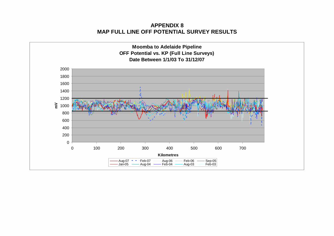
APPENDIX 8 MAP FULL LINE OFF POTENTIAL SURVEY RESULTS
Moomba to Adelaide Pipeline
OFF Potential vs. KP (Full Line Surveys)Date Between 1/1/03 To 31/12/07
0
200
400
600
800
1000
1200
1400
1600
1800
2000
0 100 200 300 400 500 600 700Kilometres
mV
Aug-07 Feb-07 Aug-06 Feb-06 Sep-05Jan-05 Aug-04 Feb-04 Aug-03 Feb-03
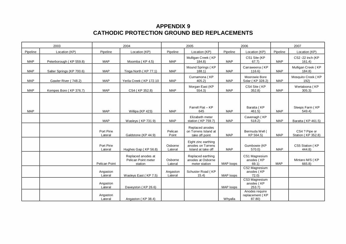
APPENDIX 9 CATHODIC PROTECTION GROUND BED REPLACEMENTS
2003 2004 2005 2006 2007
Pipeline Location (KP) Pipeline Location (KP) Pipeline Location (KP) Pipeline Location (KP) Pipeline Location (KP)
MAP Peterborough ( KP 559.8) MAP Moomba ( KP 4.5) MAP Mulligan Creek ( KP
184.8) MAP CS1 Site (KP
67.7) MAP CS2 -22 inch (KP
161.4)
MAP Salter Springs (KP 700.6) MAP Tinga North ( KP 77.1) MAP Mound Springs ( KP
188.1) MAP Carraweena ( KP
116.6) MAP Mulligan Creek ( KP
184.8)
MAP Gawler River ( 748.2) MAP Yerila Creek ( KP 172.10 MAP Curnamona ( KP
405.2) MAP Moorowie Bore
Solar ( KP 328.2) MAP Mosquito Creek ( KP
192)
MAP Kempes Bore ( KP 376.7) MAP CS4 ( KP 352.8) MAP Morgan East (KP
554.3) MAP CS4 Site ( KP
352.8) MAP Wertaloona ( KP
305.3)
MAP MAP Willipa (KP 423) MAP Farrell Flat – KP
645 MAP Baratta ( KP
461.5) MAP Sleeps Farm ( KP
549.4)
MAP Wasleys ( KP 731.9) MAP
Elizabeth meter station ( KP 759.7) MAP
Cavenagh ( KP 518.2) MAP Baratta ( KP 461.5)
Port Pirie Lateral Galdstone (KP 44.9)
Pelican Point
Replaced anodes on Torrens Island at
take off point MAP Bermuda Well (
KP 564.5) MAP CS4 ? Pipe or
Station ( KP 352.8)
Port Pirie Lateral Hughes Gap ( KP 56.8)
Osborne Lateral
Eight zinc earthing anodes on Torrens Island at take off MAP
Gumbowie (KP 570.0) MAP
CS5 Station ( KP 444.8)
Pelican Point
Replaced anodes at Pelican Point meter
station Osborne Lateral
Replaced earthing anodes at Osborne
meter station MAP loops
CS1 Magnesium anodes ( KP
69.1) MAP Mintaro M/S ( KP
665.8)
Angaston
Lateral Wasleys East ( KP 7.5) Angaston
Lateral Schuster Road ( KP
15.4) MAP loops
CS2 Magnesium anodes ( KP
72.0)
Angaston
Lateral Daveyston ( KP 26.6) MAP loops
CS3 Magnesium anodes ( KP
253.7)
Angaston
Lateral Angaston ( KP 38.4) Whyalla
Anodes require replacement ( KP
87.80)