Fissile fuel breeding with peaceful nuclear...
14
Fissile fuel breeding with peaceful nuclear explosives Su ¨mer S ¸ ahin a, *,S ¸ enay Yalc ¸in b , Kadir Yıldız c a Teknik Eg ˘ itim Faku ¨ ltesi, Gazi U ¨ niversitesi, Bes ¸evler, Ankara 06503, Turkey b Fen-Edebiyat Faku ¨ ltesi, Bahc ¸es ¸ehir U ¨ niversitesi, Istanbul, Turkey c Aksaray Mu ¨ hendislik Faku ¨ ltesi, Nig ˘ de U ¨ niversitesi, Nig ˘ de, Turkey Received 1 November 2002; accepted 1 May 2003 Abstract Neutron physics analysis of a dual purpose modified PACER concept has been conducted. A protective liquid droplet jet zone of 2 m thickness is considered as coolant, energy carrier, and fusile and fissile breeder. Flibe as the main constituent is mixed with increased mole-fractions of heavy metal salt (ThF 4 and UF 4 ) starting by 2 up to 12 mol.%. The neutronic model assumed a 30 m radius underground spherical geometry cavity with a 1 cm thick SS-304 stainless steel liner attached to the excavated rock wall. By a self-sufficient tritium breeding of 1.05 with 5 mol.% ThF 4 , or 9 mol.% UF 4 an excess nuclear fuel breeding rate of 1900 kg/year of 233 U or 3000 kg/year 239 Pu of extremely high isotopic purity can be realized. This precious fuel can be considered for special applications, such as spacecraft reactors or other compact reactors. The heavy metal constituents in jet zone acts as an energy amplifier, leading to an energy multiplication of M/1.27 or 1.65 for 5 mol.% ThF 4 , or 9 mol.% UF 4 , respectively. As an immediate result of the strong neutron attenuation in the jet zone, radiation damage with dpa B/1.4 and He B/7 ppm after a plant operation period of 30 years will be well below the damage limit values. The site could essentially be abandoned, or the cavity could be used as a shallow burial site for other qualified materials upon decommissioning. Finally, the totality of the site with all nuclear peripheral sections must be internationally safeguarded carefully. # 2003 Elsevier B.V. All rights reserved. Keywords: PACER concept; Fissile fuel; Neutron physics 1. Introduction The growing world energy needs require explor- ing new energy sources. Nuclear fusion has a great potential to provide a cheap, environmentally benign, and inexhaustible energy. At present, research efforts on fusion energy production are conducted, through two mean lines, namely mag- netic fusion energy (MFE) and inertial fusion energy (IFE). However, prognoses indicate that there is a long way until controlled fusion may become economically competitive. On the other hand, the use of nuclear explosives is the only proven and in-hand way to release fusion energy on a usefully macro scale. The idea of producing electricity through peaceful nuclear explosive * Corresponding author. Tel.: /90-312-212-4304; fax: /90- 312-212-0059. E-mail address: [email protected] (S. S ¸ ahin). Fusion Engineering and Design 65 (2003) 643 /656 www.elsevier.com/locate/fusengdes 0920-3796/03/$ - see front matter # 2003 Elsevier B.V. All rights reserved. doi:10.1016/S0920-3796(03)00397-1
Transcript of Fissile fuel breeding with peaceful nuclear...

Fissile fuel breeding with peaceful nuclear explosives
Sumer Sahin a,*, Senay Yalcin b, Kadir Yıldız c
a Teknik Egitim Fakultesi, Gazi Universitesi, Besevler, Ankara 06503, Turkeyb Fen-Edebiyat Fakultesi, Bahcesehir Universitesi, Istanbul, Turkey
c Aksaray Muhendislik Fakultesi, Nigde Universitesi, Nigde, Turkey
Received 1 November 2002; accepted 1 May 2003
Abstract
Neutron physics analysis of a dual purpose modified PACER concept has been conducted. A protective liquid
droplet jet zone of 2 m thickness is considered as coolant, energy carrier, and fusile and fissile breeder. Flibe as the main
constituent is mixed with increased mole-fractions of heavy metal salt (ThF4 and UF4) starting by 2 up to 12 mol.%.
The neutronic model assumed a 30 m radius underground spherical geometry cavity with a 1 cm thick SS-304 stainless
steel liner attached to the excavated rock wall. By a self-sufficient tritium breeding of 1.05 with 5 mol.% ThF4, or 9
mol.% UF4 an excess nuclear fuel breeding rate of 1900 kg/year of 233U or 3000 kg/year 239Pu of extremely high isotopic
purity can be realized. This precious fuel can be considered for special applications, such as spacecraft reactors or other
compact reactors. The heavy metal constituents in jet zone acts as an energy amplifier, leading to an energy
multiplication of M�/1.27 or 1.65 for 5 mol.% ThF4, or 9 mol.% UF4, respectively. As an immediate result of the
strong neutron attenuation in the jet zone, radiation damage with dpaB/1.4 and HeB/7 ppm after a plant operation
period of 30 years will be well below the damage limit values. The site could essentially be abandoned, or the cavity
could be used as a shallow burial site for other qualified materials upon decommissioning. Finally, the totality of the
site with all nuclear peripheral sections must be internationally safeguarded carefully.
# 2003 Elsevier B.V. All rights reserved.
Keywords: PACER concept; Fissile fuel; Neutron physics
1. Introduction
The growing world energy needs require explor-
ing new energy sources. Nuclear fusion has a great
potential to provide a cheap, environmentally
benign, and inexhaustible energy. At present,
research efforts on fusion energy production are
conducted, through two mean lines, namely mag-
netic fusion energy (MFE) and inertial fusion
energy (IFE). However, prognoses indicate that
there is a long way until controlled fusion may
become economically competitive. On the other
hand, the use of nuclear explosives is the only
proven and in-hand way to release fusion energy
on a usefully macro scale. The idea of producing
electricity through peaceful nuclear explosive
* Corresponding author. Tel.: �/90-312-212-4304; fax: �/90-
312-212-0059.
E-mail address: [email protected] (S. Sahin).
Fusion Engineering and Design 65 (2003) 643�/656
www.elsevier.com/locate/fusengdes
0920-3796/03/$ - see front matter # 2003 Elsevier B.V. All rights reserved.
doi:10.1016/S0920-3796(03)00397-1
(PNE) devices has been elaborated gradually sinceearly 1960s. Sound proposals are evaluated for
power production by repetitive nuclear explosions
contained in an underground cavity [1�/9]. One of
the most prospective ideas turns out to be the so-
called modified PACER concept. The problems
concerning chamber design under consideration of
the mechanical forces following the explosion,
fireball pressure dynamics and equilibrium pres-sure have been discussed in [6�/9].
Preceding calculations have further shown that
for a Flibe zone thickness of �/2.5 m, the
activation of the steel liner and rock would be
low enough after 30 years of operation that the
cavity would satisfy the US Nuclear Regulatory
Commission’s rules for ‘‘shallow burial’’ upon
decommissioning, assuming other sources ofradioactivity could be removed or qualified as
well. This implies that upon decommissioning, the
site could essentially be abandoned, or the cavity
could be used as a shallow burial site for other
qualified nuclear waste materials. It is tacitly
understood that a power plant site on the basis
of nuclear explosives must be constructed in a
remote uninhabited area.The modified PACER concept [7�/9] was eval-
uated for power production, only. However, being
a neutron reach source, a fusion power plant can
also be used for fissile fuel breeding (FFB). For
that reason, the flowing liquid zone will be
composed of a mixture of Flibe and fissionable
heavy metal salt (ThF4 and UF4) for the
purpose of a self-sufficient tritium breeding forthe PNE power plant and for FFB for utilization
in external light water reactors (LWRs) in the
present work.
2. The PACER concept
In the modified PACER concept, the layout of
the generic power station is shown in Fig. 1, asadopted from [8,9], which was also originally
adopted from [10,11]. The parts of such a plant
are an underground containment vessel, the ex-
plosive with its operating mechanism, the heat-
transfer system, the electric generator, the cooling
system, the nuclear material reprocessing plant
and the explosive manufacturing plant. A simpli-
fied sequence of operations in the power plant is
shown in Fig. 2, as adopted from [9].
The explosion yield is 2 kt (8.36 TJ) every 40
min in a 20 m radius cylindrical cavity, carefully
engineered with a 1-cm-thick stainless steel liner.
The liner is secured to the rock with regularly
spaced and pre-stressed rock bolts or tendons.
These measures lead to a reasonably reduced the
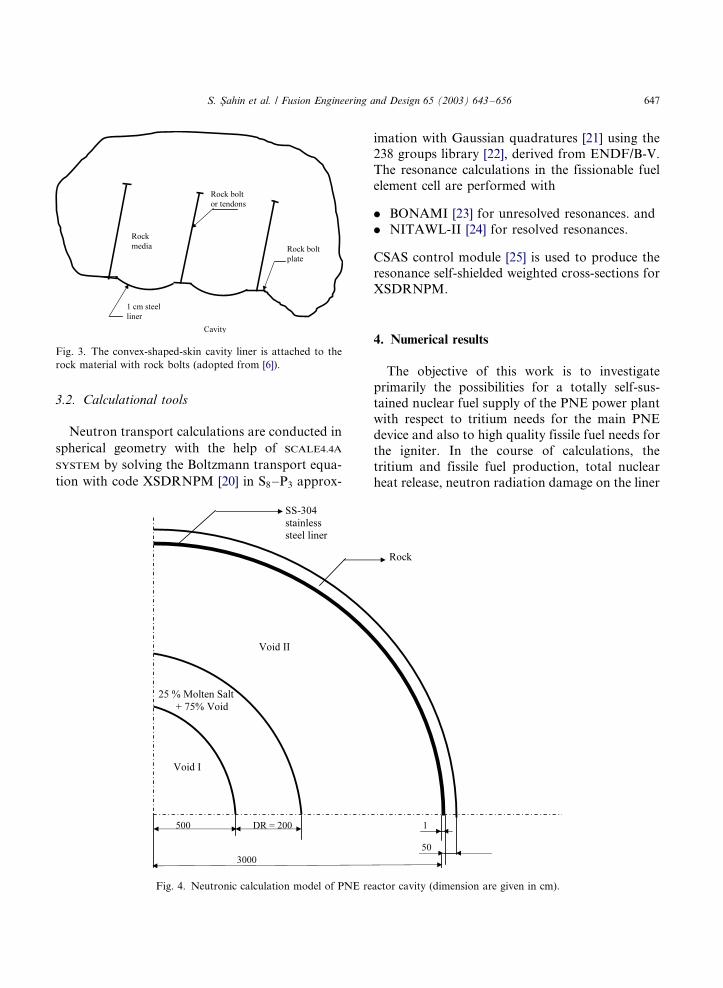
cavity volume [6,7]. The steel skin is convex to
keep it tightly stretched against the rock, as shown
in Fig. 3, adopted from [6]. The liner prevents a
contamination of the molten salt with rock mate-
rial and reinforces the rock media. Liquid jets or
streams surround the explosion in order to reduce
the mechanical forces on the steel liner from the
dynamic stresses caused by the shocks from the
explosion. An alternative way for shock suppres-
sion system using springs and shock absorbers
behind plates is presented in [12]. However, liquid
jets have the fundamental advantage of the
instantaneous recovery. In this concept, the work-
ing fluid is molten salt, Li2BeF4 (Flibe), in the
form of vertically flowing jets, to absorb energy
and protect the liner from shocks. This allows
much of the energy to evaporate the liquid and
keeps a reduced pressure �/3 MPa in the cavity
right after the explosion. Also, because tritium is
practically insoluble in the molten salt, it can be
removed almost completely, thus allowing a very
low tritium inventory in the range of �/100 Ci by
using Flibe [6].
In the present work, while Flibe remains as the
main constituent of vertically flowing jets, now it is
mixed with increased mole-fractions of heavy
metal salt (ThF4 and UF4), starting by 2 up to
12 mol.%, for the purpose of high quality FFB,
under consideration of a self-sufficient tritium
breeding for the PNE fusion device. High quality
fissile fuel will be needed primarily for the
igniter of the PNE device. Excess fissile fuel can
be used for external spacecraft reactors or other
advanced reactor systems. Actual LWRs are
operating with low enriched nuclear fuel so that
high quality fissile fuel could be utilized more
economical in compact reactors for special mis-
sions.
S. Sahin et al. / Fusion Engineering and Design 65 (2003) 643�/656644

3. Calculational procedure
In the course of the numerical analysis, the
cylindrical cavity was simulated by a spherical one.
This substitution allowed us to perform a series of
fast, one-dimensional multi-group neutron trans-
port calculations with a sufficiently high resolutionin the neutron energies of interest. The neutron
source is evaluated, based on a fusion nuclear
explosive device.
3.1. Geometrical model for neutronic calculations
A rigorous neutronic study at advanced design
stage would require three-dimensional calculationtools. However, for the purpose of a generic study
with fast, multiple computer runs, one-dimen-
sional calculations will be preferred, for simplicity.
Any type of a fusion blanket must cover the
neutron source over a space angle of 4p to confine
the fusion neutrons, among other reasons. One-
dimensional slab or cylinder would represent open
geometries. Therefore, calculations are conducted
in this and related previous work, preferably in
one-dimensional spherical geometry under consid-
eration of the neutron spectrum softening due to
neutron backscattering into the cavity in a closed
geometry [13�/17].
Fig. 4 shows the neutronic calculation model of
the cavity. The space, where the PNE device is
located in a spherical cavity with a radius of R�/5
m. The molten salt zone consisting of liquid jets
has a radial thickness of DR�/2.0 m. The basic
constituent of molten salt is Flibe. Previous work
has shown that a Flibe jets zone of DR�/�/2 m
would reduce the residual reactivity to such low
levels that the 10CFR61 regulations [18] can be
satisfied for a C-class nuclear waste disposal after
decommissioning [13�/17]. In the present work,
heavy metal in form of ThF4 or UF4 has been
added to Flibe for the purpose of FFB. The
molecular fraction of the latter component is
Fig. 1. Schematic diagram of a PNE reactor power station. The diagram identifies its principal components (adopted from [8,9]).
S. Sahin et al. / Fusion Engineering and Design 65 (2003) 643�/656 645

gradually increased from 2 up to 12% in the
coolant. The cavity is lined with 1 cm-thick
stainless steel of type SS-304. Steel structures can
be made of SS-304 steel rather than of SS-316 due
to the lack of corrosive water in the cavity in order
to satisfy the 10CFR61 regulations with more
safety margin. Beyond the liner, a 50-cm rock
zone is used to consider the neutron reflection
back into the cavity. For DR�/50 cm, the
neutrons reaching the rock zone could act practi-
cally infinite with respect to neutron reflection.
Table 1 shows the atomic densities of the
materials, as used in the calculations. The atomic
densities for rock around the cavity were adopted
to correspond to the average values in the Nevada
region [19]. We assumed the neutron source to be
entirely 14 MeV, as the authors are not interested
in nuclear weapon design.
Fig. 2. Sequence of events in the operation of a PNE reactor (adopted from [9]).
S. Sahin et al. / Fusion Engineering and Design 65 (2003) 643�/656646
3.2. Calculational tools
Neutron transport calculations are conducted in
spherical geometry with the help of SCALE4.4A
SYSTEM by solving the Boltzmann transport equa-
tion with code XSDRNPM [20] in S8�/P3 approx-
imation with Gaussian quadratures [21] using the238 groups library [22], derived from ENDF/B-V.
The resonance calculations in the fissionable fuel
element cell are performed with
. BONAMI [23] for unresolved resonances. and
. NITAWL-II [24] for resolved resonances.
CSAS control module [25] is used to produce the
resonance self-shielded weighted cross-sections for
XSDRNPM.
4. Numerical results
The objective of this work is to investigate
primarily the possibilities for a totally self-sus-
tained nuclear fuel supply of the PNE power plantwith respect to tritium needs for the main PNE
device and also to high quality fissile fuel needs for
the igniter. In the course of calculations, the
tritium and fissile fuel production, total nuclear
heat release, neutron radiation damage on the liner
Fig. 3. The convex-shaped-skin cavity liner is attached to the
rock material with rock bolts (adopted from [6]).
Fig. 4. Neutronic calculation model of PNE reactor cavity (dimension are given in cm).
S. Sahin et al. / Fusion Engineering and Design 65 (2003) 643�/656 647

are evaluated. Excess fissile fuel production for the
external use will also be calculated. In the first
step, neutron spectrum in the cavity has been
evaluated.
4.1. Neutron spectrum
We assumed the neutron source to be entirely 14
MeV. In previous work, an attempt to assess the
correct neutron leakage spectrum out of a PNE
has shown that this would not be reliable without
an exact knowledge of the geometry and material
composition of the explosive [26]. As the authorsare not interested in nuclear weapon design, we
also assumed that any material surrounding the
neutron source could be considered equivalently to
be internal part of the molten salt zone with
respect to spectral displacements. In a reflection
with inertial confined fusion (ICF), we remember
Table 1
Atomic densities of the materials, as used in the calculations
Material Nuclide Nuclei density
(1024/cm3)
Molten salt (UF4)0.02 �/(Li2BeF4)0.98238U 5.98835E-05a
235U 4.22139E-0719F 1.20611E-029Be 2.95497E-037Li 5.46670E-046Li 4.43246E-04
Molten salt (UF4)0.04 �/(Li2BeF4)0.96238U 1.19917E-04235U 8.45340E-0719F 1.20763E-029Be 2.89831E-037Li 5.36187E-036Li 4.34746E-04
Molten salt (UF4)0.06 �/(Li2BeF4)0.94238U 1.80103E-04235U 1.26961E-0619F 1.20915E-029Be 2.84150E-037Li 5.25677E-036Li 4.26225E-04
Molten salt (UF4)0.08 �/(Li2BeF4)0.92238U 2.40439E-04235U 1.69494E-0619F 1.21067E-029Be 2.78454E-037Li 5.15141E-036Li 4.17682E-04
Molten salt (UF4)0.10 �/(Li2BeF4)0.90238U 3.00928E-04235U 2.12135E-0619F 1.21220E-029Be 2.72745E-037Li 5.04578E-036Li 4.09117E-04
Molten salt (UF4)0.12 �/(Li2BeF4)0.88238U 3.61570E-04235U 2.54883E-0619F 1.21373E-029Be 2.67021E-037Li 4.93988E-036Li 4.00531E-04
Molten salt (ThF4)0.02 �/(Li2BeF4)0.98232Th 6.02221E-0519F 1.20444E-029Be 2.95088E-037Li 5.45914E-036Li 4.42633E-04
Molten salt (ThF4)0.04 �/(Li2BeF4)0.96232Th 1.20429E-0419F 1.20429E-029Be 2.89028E-037Li 5.34703E-036Li 4.33543E-04
Molten salt (ThF4)0.06 �/(Li2BeF4)0.94232Th 1.80619E-0419F 1.20413E-029Be 2.82970E-037Li 5.23495E-036Li 4.24455E-04
Table 1 (Continued )
Material Nuclide Nuclei density
(1024/cm3)
Molten salt (ThF4)0.08 �/(Li2BeF4)0.92232Th 2.40794E-0419F 1.20397E-029Be 2.76913E-037Li 5.12289E-036Li 4.15370E-04
Molten salt (ThF4)0.10 �/(Li2BeF4)0.90232Th 3.00953E-0419F 1.20381E-029Be 2.70858E-037Li 5.01087E-036Li 4.06287E-04
Molten salt (ThF4)0.12 �/(Li2BeF4)0.88232Th 3.61097E-0419F 1.20366E-029Be 2.64804E-037Li 4.89888E-036Li 3.61097E-04
SS-304 C 1.47870E-05
Fe 6.01898E-02
Ni 8.59854E-03
Si 3.43942E-04
Cr 1.63372E-02
Rock (Nevada r�/1.63 g/cm3) [18] H 9.61300E-03
O 3.57300E-02
Mg 4.90100E-04
Na 4.45200E-04
Al 4.50800E-04
Fe 3.42700E-04
Si 1.16400E-04
a Read as 5.98835�/10�5.
S. Sahin et al. / Fusion Engineering and Design 65 (2003) 643�/656648

that an ICF target has a 1000�/ of liquid density.Whereas, a fusion zone of a PNE will have at most
20�/50�/ of liquid density.
With that assumption in mind, transport calcu-
lations are conducted to evaluate the space- and
energy dependent neutron spectrum in the cavity.
As one can see in Fig. 4, the 14 MeV energetic
fusion source neutrons arrive, practically unhin-
dered through the first void, to the liquid jetregion. Majority of neutron interactions takes
place in the molten salt coolant and shape the
neutron spectrum. Then, again the leaking neu-
trons pass the second void region and penetrate
through the liner into the rock. Further neutron
interactions occur in the rock. Neutron spectrum
in the coolant determines all pertinent neutron
reaction rates, and has hence primary importance.Calculations have shown that the increase of
heavy metal along with the decrease of lithium has
compensating effects on neutron absorption with
very minor effects on the spectrum, keeping the
latter practically unchanged for the investigated
coolant compositions. Addition of the heavy to the
coolant increases slightly the induced fission
neutron part in the spectrum. Flibe has dominat-ing effects on the spectrum formation due to the
light elements, such as Be and Li.
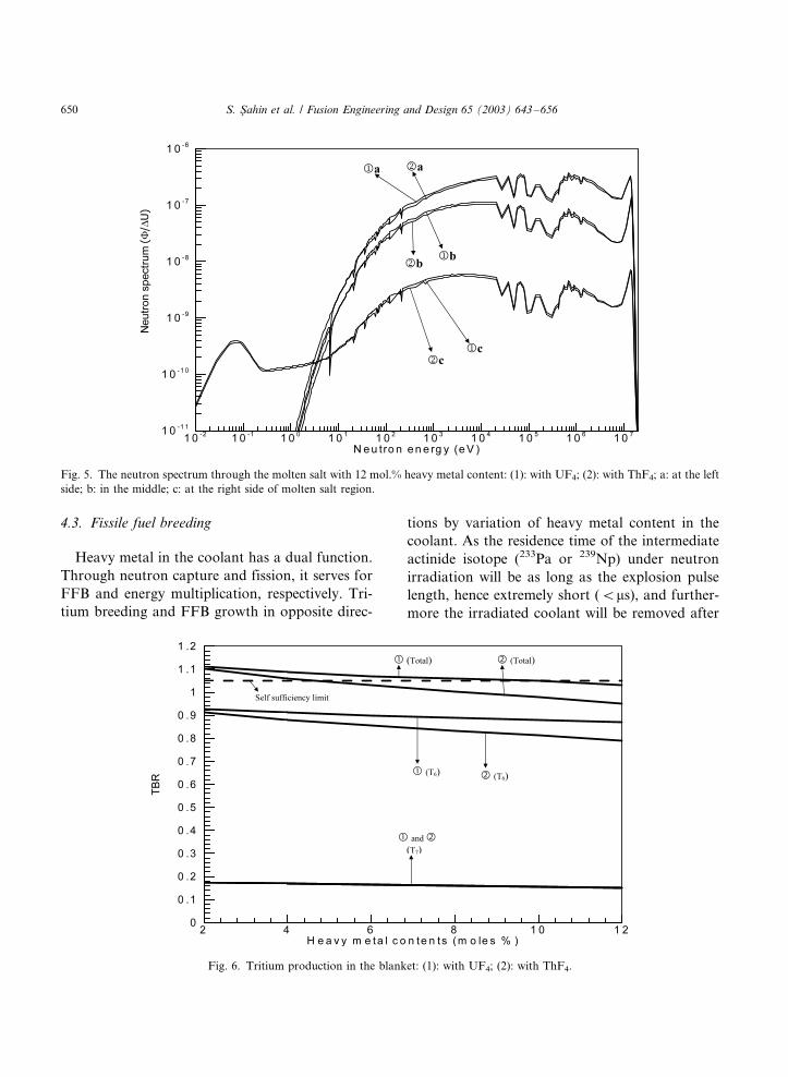
Fig. 5 shows the neutron spectrum by deep
penetration through the molten salt with 12 mol.%
heavy metal. Spectrum consists of the uncollided
fusion source neutrons, collided neutrons and
secondary fission neutrons. Strong resonance
depths are noticed with the presence of UF4.Towards the right border of the jet zone, a
remarkable neutron thermalization throughout
the coolant region is observed resulting with a
typical Maxwellian shape in thermal energies.
Neutrons will be multiplied in the coolant via
fission and (n, 2n) in the coolant. To some degree,
also (n, 3n) reactions will occur in the heavy metal.
Although a great fraction of neutrons will also beabsorbed in situ, some neutrons will leak out of the
coolant. Right neutron leakage fraction out of
coolant towards the liner increases very slightly
from 12.4 to 12.7% for 2 to 12 mol.% UF4
fraction, respectively, and decreases very slightly
from 12.3 to 11.9% for 2�/12 mol.% ThF4 fraction,
respectively. The higher neutron multiplication in
UF4 causes this very slight increase of rightneutron leakage fraction despite a stronger neu-
tron absorption in natural uranium.
4.2. Fusile fuel (tritium) breeding
Like every fusion reactor concept, also a PNE
power plant must produce its own artificial and
radioactive fusile fuel tritium in the course of
operation for a self-sustained fusion fuel supply.For that reason a tritium breeding ratio (TBR)�/
1.05 can be considered satisfactory. In recent
work, an extensive neutronic analysis of the
modified PACER concept has been carried out
[27]. Using Li2BeF4 as the working fluid in form of
vertically flowing jets with a volume fraction of
25%, Flibe zone thickness of 1.6 and 2 m were
evaluated for a TBR value of 1.05 and 1.15,respectively. In the present work, by a liquid
zone thickness of 2.0 m, lithium is gradually
replaced with heavy metal for the purpose of
fissile breeding. Along with the increase of the
heavy metal fraction in the jets, fusile breeding
rates will decline and fissile breeding rates will
grow in adverse sense.
Fig. 6 depicts the TBR as a function of theheavy metal fraction in the coolant. While the T7
value (TBR in 7Li) remains the same for both UF4
and ThF4, and furthermore practically unchanged
over a long fraction range, T6 value (TBR in 6Li)
drops along with increasing heavy metal fraction.
Also, higher neutron multiplication in natural
uranium than in thorium leads to a higher
production for low energy neutrons, resulting inhigher neutron absorption in 6Li and consequently
with higher T6, in the former.
According to the total TBR values in Fig. 6, Flibe
coolant with up to 5 mol.% ThF4 or with up to 9
mol.% UF4 will allow a self-sufficient tritium
breeding by a thickness of 2 m. Previous work
has indicated that the TBR increases according to
the fitted analytical relation TBR�/A tanh(b �/DR)c with increasing coolant zone thickness DR,
and reaches soon beyond �/2 m an asymptote [27].
Of course, with U and Th fluorides in the Flibe jets,
the constants in the analytical relation will be
slightly different, but the shape of the analytical
function will have, more or less, a similar character.
S. Sahin et al. / Fusion Engineering and Design 65 (2003) 643�/656 649
4.3. Fissile fuel breeding
Heavy metal in the coolant has a dual function.
Through neutron capture and fission, it serves for
FFB and energy multiplication, respectively. Tri-
tium breeding and FFB growth in opposite direc-
tions by variation of heavy metal content in the
coolant. As the residence time of the intermediate
actinide isotope (233Pa or 239Np) under neutron
irradiation will be as long as the explosion pulse
length, hence extremely short (B/ms), and further-
more the irradiated coolant will be removed after
Fig. 5. The neutron spectrum through the molten salt with 12 mol.% heavy metal content: (1): with UF4; (2): with ThF4; a: at the left
side; b: in the middle; c: at the right side of molten salt region.
Fig. 6. Tritium production in the blanket: (1): with UF4; (2): with ThF4.
S. Sahin et al. / Fusion Engineering and Design 65 (2003) 643�/656650

each explosion out of the reactor cavity, the newlyproduced fissile fuel will be of extreme isotopic
purity, never attainable in conventional reactors.
For that reason, it would be, to a certain degree, a
waste to use this high quality fuel in standard
nuclear reactors. It would be rather predestinated
for new application fields, such as space craft or
other types of compact reactors.
Some of the fissile fuel can be utilized for thefission trigger of the PNE device, which can be
roughly estimated. In a well developed PNE
device, most of the explosion energy must be
supplied by fusion. We assume that the fission
trigger can be designed as compact as possible so
that by a well developed compression technique its
explosion energy will be �/10% of the fusion
component, namely �/0.2 kT/shot. For thatenergy release, the fissile fuel consumption will
be �/10 g/shot or �/130 kg/year. The rest of the
fissile fuel (unburnt fraction) in the PNE device
will be mixed with the coolant together with other
explosion debris and can be recuperated along
with the new fissile fuel in the coolant. Fig. 7
shows the gross (total) FFB/year and the net fissile
fuel production for external use by a repetitionrate of 40 min/shot for a full power year.
4.4. Nuclear energy generation
In addition to the fusion explosion energy of the
PNE device, there will be some additional nuclear
energy production in the molten jet zone. The 238
group’s library in the SCALE4.4A SYSTEM contains
only neutron energy groups and not the g-rays.
Heat production data with inclusion of all nuclear
reactions are not processed in this cross section set.
Within the framework of the present work and forthe purpose of an assessment of nuclear heating in
the coolant, neutron induced fission reactions in
heavy metal and the main energetic reactions in
lithium, namely 6Li(n, a)T and 7Li(n, an?)Treactions have been considered, as in equation
(1), which constitute major components of nuclear
power production.
E��SfF�180 MeV��T6�4:784 MeV
��T7�2:467 MeV (1)
Natural uranium and thorium become fission-able under high energetic fusion neutron irradia-
tion, and produce power. Fig. 8 depicts the
integral fission rate in the coolant per incident
fusion neutron as a function of heavy metal
content in the coolant. Natural uranium is to a
higher degree fissionable than thorium. Integral
fission in UF4 and ThF4 increases by a factor of 5
and 4.9, respectively, for an increase of heavymetal from 2 to 12% in the coolant. Despite this
relative increase, total integral fission rate remains
very low, namely only a few% with UF4 and B/1%
with ThF4 leading to only a modest and minor
energy multiplication, respectively, in the PNE
power plant system. Main energy source in the
modified PACER system with fissionable remain
the PNE device.Fig. 9 shows the total energy multiplication
factor M in the PNE reactor. With UF4 in the
coolant, M increases by 35% from 2 to 12% heavy
metal in the coolant. On the other hand, M
increases by only 6.6% from 2 to 12% thorium in
the coolant. The energy production in 6Li and in
thorium remains nearly comparable so that the
depletion in 6Li is barely compensated by replace-ment with thorium. Therefore, the contribution of
ThF4 to energy multiplication becomes almost
negligible. Under consideration of a self-sufficient
tritium breeding (TBR�/1.05), the upper limits are
5 mol.% for ThF4 and 9 mol.% for UF4, Section
4.2. Then, the upper energy multiplication values
will be M�/1.27 for 5 mol.% ThF4, and 1.65 for 9
mol.% UF4.Total nuclear heat production will consists of (1)
the explosion energy of the PNE device and (2) the
instantaneous, isochoric, neutron induced heat
release in the coolant. Fig. 10 shows the induced
nuclear heat density in the coolant zone as a
function of the distance from the neutron source.
The instantaneous energy generation density at the
time of explosion is very high. Fission has anexponentially decreasing character with increasing
distance from the neutron source due to a rela-
tively high threshold fission energy in 232Th (1.4
MeV) and 238U (0.8 MeV). On the other hand, the
exothermic 6Li(n, a) reactions are dominated by
low energy secondary neutrons and have a cosine
like flat character.
S. Sahin et al. / Fusion Engineering and Design 65 (2003) 643�/656 651

Explosion and the induced nuclear energy will
create a fireball and the total energy produced will
be transferred to the stream of droplets. Jets will
continue to cool vapor. Temperature and pressure
will drop to 1500 K and 1 atm in 0.1 s. The
explosion will mix up all the coolant in the
chamber and very quickly an almost homogenous
and isothermal coolant will be accumulated at the
bottom, indicated in Fig. 2. Molten salt will then
be pumped to heat exchanger.
Contribution of g-rays to total nuclear heat is
discussed in Section 4.5.
Fig. 7. FFB per incident fusion neutron.
Fig. 8. The integral fission rate in the coolant per incident fusion neutron as a function of heavy metal content in the coolant: (1): with
UF4; (2): with ThF4.
S. Sahin et al. / Fusion Engineering and Design 65 (2003) 643�/656652

4.5. Contribution of g-rays to nuclear heat
In Section 4.4, the nuclear power production is
analyzed with the help of the 238 neutron group
library in a fine energy resolution and under
consideration of resonance effects for each pro-
blem, individually. Previous work had demon-
strated clearly the importance of a fine neutron
energy resolution and consideration of resonance
effects for fusion blanket neutronic studies [27].
However, the heat production data considering all
nuclear reactions are not processed in the 238
group cross sections set [22]. For an assessment of
the contribution of g-rays on total nuclear heating,
a 30 neutron�/12 g-ray group transport and
activity cross section data library CLAW-IV [29]
has been used.
CLAW-IV represents an extended version of the
Los Alamos National Laboratory (LANL) cross
section data library CLAW [30], has point cross
section linearization and resonance reconstruction
tolerance of 0.5%, and all microscopic cross
sections are Doppler broadened to 300 K. The
neutron cross sections are averaged over 30 energy
groups using the Bondarenko [31] flux approxima-
tion with a fusion, fission, 1/E, thermal weight
function. The energy structure is such that it has
12, 9 and 9 neutron groups in the MeV, keV and
Fig. 9. The total energy multiplication factor M in the PNE reactor: (1): with UF4; (2): with ThF4.
Fig. 10. Components of the nuclear power density vs. radius:
(1): with 12% UF4 content; (2): with 12% ThF4 content; (3):
with 2% UF4 content; (4): with 2% ThF4 content; */, total
nuclear heating; - �/- �/- �/-, (n, f) heating; -----, 6Li(n, t)4He heating.
S. Sahin et al. / Fusion Engineering and Design 65 (2003) 643�/656 653

eV including thermal regions, respectively. Thecoupled 30 neutron�/12 g-ray group data set
includes also neutron induced secondary g-rays.
The heat production data has been processed
under consideration of all energy producing nu-
clear reactions.
The transport calculations with the data library
CLAW have been performed by solving the
Boltzmann transport equation with the SN trans-port code ANISN [28]. The contribution of g-rays
on total nuclear heating will grow in the presence
of heavier elements. Especially, in mainline fusion
reactor design concept, the metallic structures will
be the major source of g-ray heating. In the
coolant zone of the PACER concept, there are
no metals with the exception of fissionable iso-
topes. We have calculated the g-ray heating for thelowest (2%) and highest (12%) uranium salt as he
extreme cases.
Table 2 shows the integral heat production in
the coolant for these compositions. One can notice
that the g-ray causes �/20% of the induced nuclear
heating in the coolant. As the main and primary
energy source in a PNE reactor will be the PNE
device itself, the g-ray heating will constitute onlya few% of the total plant energy generation.
Compared with 238 group data library in SCA-
LE4.4A, CLAW cross section set underestimates
the nuclear heating. In a separate work, we have
demonstrated the importance of high neutron
energy group resolution as well as consideration
of resonance self-shielding for each structure,
individually [32]. Therefore, the 238 group datalibrary is used throughout this study preferably.
4.6. Neutron radiation damage
In the power plant, the only part exposed to
nuclear radiation will be the steel liner at the
periphery of the cavity, Fig. 3. All other compo-
nents are totally separated from the nuclear zone.
Beside thermo mechanical forces, the liner maysuffer material damage under intense neutron
radiation.
The displacement of an atom from its lattice
position results from transferring a threshold
energy, typically of the order of few dozens of
electron volts, to the target. Atomic displacements
are the fundamental process of radiation damage
in metals. Calculations are conducted to deter-
mine, whether displacements of the atoms from
their lattice sites as a result of collisions with
highly energetic fusion neutrons can become a
serious damage mechanism at the cavity liner.
At present there is non consensus about the
damage limit criteria structural materials. Blink
[33] suggests a DPA value of 165 for SS-316,
though admitting that the DPA limit might be
significantly higher than 165. The same limit is
applied in [34]. A more conservative DPA value of
100 is assumed in [35,36]. Due to lack of experi-
mental data, it is too early to state whether the
actual DPA limit might be significantly higher
than those. In an earlier work, DPA limits of the
first-wall materials for MFE reactors and for IFE
reactors were indicated as DPA�/300�/1000 [37].
Only experiments conducted with an intense fusion
neutron source can provide clarification about
realistic damage limit data for advanced design
work.
On the liner, we have calculated DPA values
between 1.3 and 1.4 at the liner after an operation
time of 30 full power years for the investigated
coolant mixture range. Hence, no displacement
damage is expected to occur in the liner.
An other very serious damage mechanism for
structural materials can become gas production in
the metallic lattice resulting from diverse nuclear
reactions, mainly through (n, p) and (n, a) and to
some extent through (n, d) and (n, t) reactions
above a certain threshold energy. Materials suffer
Table 2
Nuclear heat production in the coolant (in 10�13 J/source
fusion neutron)
Coolant type
0/
2% UF4�/98% Li2-
BeF4
12% UF4�/88% Li2-
BeF4
I 6.50 17.37
II 7.86 (17% g-ray) 22.05 (21% g-ray)
III 9.11 22.22
I: Neutron heat production calculated with 30 neutron
groups (CLAW-IV). II: Neutron�/g-ray heat production cal-
culated with 30 neutron groups�/12 g-ray groups (CLAW-IV).
III: Heat production calculated with 238 neutron groups
(SCALE) according to equation (1).
S. Sahin et al. / Fusion Engineering and Design 65 (2003) 643�/656654

from embrittlement due to gas bubble formationeven for fission applications, which is in general at
lower MeV range. The hydrogen isotopes will
diffuse out of the metallic lattice under high
operation temperatures, but a-particle’s will re-
main in metal and generate helium gas bubbles.
These reactions may limit the lifetime of the liner.
Blink and Perlado et al. [33,34] suggest a helium
limit of 500 appm in steel. We have calculatedhelium production values below 7 and 4 ppm at
the liner after an operation time of 30 full power
years. Helium gas production will not cause a
material damage at the liner during the life time of
the plant.
5. Conclusions
The study has been conducted to assess the
potential of the PACER concept for FFB in
addition to electricity generation. It turns out
that a PNE reactor can breed high quality nuclear
fuel with extreme isotopic purity while producing
energy.
Only a few mol.% of heavy metal in the moltensalt will produce sufficient fissile fuel for the fission
trigger of the PNE device. A Flibe coolant with up
to 5 mol.% ThF4 or with up to 9 mol.% UF4 will
allow a self-sufficient tritium breeding by a thick-
ness of 2 m and with 25% liquid density in the jet
zone. Heavy metal will be needed for an absolutely
nuclear fuel independent operation of the PNE
plant. Excess fissile fuel will be suitable for space-craft applications or for other compact nuclear
reactors.
Molybdenum is the main source for post shut
down activity in steel structure of a fusion plant
[15]. Use of SS-304 stainless steel without molyb-
denum constituent instead of SS-316 stainless steel
in the absence of water coolant eliminates all
residual radio activity originating from this mate-rial [17]. Low activation of the steel liner after 30
year of operation, satisfying the US Nuclear
Regulatory Commission’s rules for ‘‘shallow bur-
ial’’ upon decommissioning, assuming other
sources of radioactivity could be removed or
qualified as well, would make further utilization
the site possible. The cavity could be used as ashallow burial site for other qualified materials.
On the other hand, a PNE power plant is of
highly prolific nature. The site with all nuclear
peripheral sections, including explosive device
manufacturing, power plant and fuel reprocessing
must be sealed hermetically against nuclear diver-
sion. Careful international nuclear safeguarding
will be required.
Acknowledgements
This work has been supported by the ResearchFund of the Gazi University, Projects # 07/2001-
15; 2003-14 and DPT-2003K 120470-08.
References
[1] Engineering with Nuclear Explosives, Proceedings of Third
Plowshare Symposium, TID-7695, US Department of
Energy/Office of Scientific and Technical Information,
Oak Ridge, TN, 1964.
[2] E. Teller, W. Talley, G. Higgins, Constructive Uses of
Nuclear Explosives, McGraw-Hill Book Company, New
York, 1968.
[3] H.W. Hubbard, Project PACER Final Report, RDA-TR-
4100-003, R&D Associates, 1974.
[4] R.P. Hammond, Practical fusion power, Mech. Eng. 104
(1982) 34.
[5] W. Seifritz, PACER: a ground design for fusion power,
Fusion 4 (1980) 22.
[6] R.W. Moir, PACER revisted, Fusion Technol. 15 (1989)
1114.
[7] C.J. Call, R.W. Moir, A novel fusion power concept based
on molten-salt technology: PACER revisted, Nucl. Sci.
Eng. 104 (1990) 364.
[8] A. Szoke, R.W. Moir, A practical route to fusion power,
Technol. Rev. 94 (1991) 20.
[9] A. Szoke, R.W. Moir, A realistic, gradual and economical
approach to fusion power, Fusion Technol. 20 (1991) 1012.
[10] R.P. Hammond, Practical fusion power, Mech. Eng. 104
(1982) 34.
[11] H.W. Hubbard, Project PACER Final Report, R&D
Associates, Santa Monica, CA, RDA-TR-4100-003, 1974.
[12] V. David, A mechanical decoupling of underground
nuclear explosion shock waves from the explosion cavity
walls, Trans. Am. Nucl. Soc. 56 (1988) 127.
[13] S. .Sahin, R.W. Moir, J.D. Lee, S. Unalan, Neutronic
investigation of IFE blankets for HYLFE-II and MHD
applications, Fusion Technol. 25 (1994) 388.
S. Sahin et al. / Fusion Engineering and Design 65 (2003) 643�/656 655
[14] S. .Sahin, R.W. Moir, S. Unalan, Neutronic investigation
of a power plant using peaceful nuclear explosives, Fusion
Technol. 26 (1994) 1311.
[15] S. .Sahin, R.W. Moir, A. Sahinaslan, H.M. Sahin, Radia-
tion damage in liquid-protected first wall materials for
IFE-reactors, Fusion Technol. 30 (1996) 1027.
[16] S. Sahin, A. Sahinaslan, M. Kaya, S. Yılmaz, Radiation
Damage in Liquid-Protected First-Wall Materials for
MFE-Reactors, Transactions of the American Nuclear
Society 1997 Winter Meeting, 77 (16�/20 November 1997)
158 (Albuquerque).
[17] J.D. Lee, Waste disposal assessment of HYLIFE-II
structure, Fusion Technol. 26 (1994) 74.
[18] Licensing Requirements for Land Disposal of Radioactive
Waste, Code of Federal Regulations, Title 10, Part 61
(1982).
[19] S. .Sahin, Examination of the radiation protection cap-
ability of different types of battle tanks against neutron
bomb, Bull. Technical Univ. Istanbul 40 (1987) 315.
[20] N.M. Greene, L.M. Petrie, XSDRNPM, A One-Dimen-
sional Discrete-Ordinates Code For Transport Analysis,
NUREG/CR-0200, Revision 5, vol. 2, Section F3, ORNL/
NUREG/CSD-2/V2/R5, Oak Ridge National Laboratory,
1997.
[21] S. Sahin, Radiation Shielding Calculations for Fast
Reactors (in Turkish), Faculty of Science and Literature,
Gazi University, Publication # 169, Publication number
22, Ankara, Turkey.
[22] W.C. Jordan, S.M. Bowman, Scale Cross-Section Li-
braries, NUREG/CR-0200, Revision 5, vol. 3, section
M4, ORNL/NUREG/CSD-2/V3/R5, Oak Ridge National
Laboratory, 1997.
[23] N.M. Greene, BONAMI, Resonance Self-Shielding by the
Bondarenko Method, NUREG/CR-0200, Revision 5, vol.
2, section F1, ORNL/NUREG/CSD-2/V2/R5, Oak Ridge
National Laboratory, 1997.
[24] N.M. Greene, L.M. Petrie, R.M. Westfall, NITAWL-II,
Scale System Module For Performing Resonance Shielding
and Working Library Production, NUREG/CR-0200,
Revision 5, vol. 2, Section F2, ORNL/NUREG/CSD-2/
V2/R5, Oak Ridge National Laboratory, 1997b.
[25] N.F. Landers, L.M. Petrie, CSAS, Control Module For
Enhanced Criticality Safety Analysis Sequences, NUREG/
CR-0200, Revision 5, vol. 1, Section C4, ORNL/NUREG/
CSD-2/V1/R5, Oak Ridge National Laboratory, 1997.
[26] S. .Sahin, B. Sarer, Assesment of the neutron leakage
spectrum of an enhanced radiation warhead for applica-
tion as peaceful nuclear explosive, Kerntechnik 58 (1993)
295.
[27] S. .Sahin, R.W. Moir, S. Unalan, Neutronic investigation
of a power plant using peaceful nuclear explosives, Fusion
Technol. 26 (1994) 1311.
[28] W.W. Engle, Jr, ANISN, A One-Dimensional Discrete
Ordinates Transport Code with Anisotropic Scattering,
K1693, Oak Ridge National Laboratory, 1970.
[29] T.A. Al-Kusayer, S. Sahin, A. Drira, CLAW-IV, Coupled
30 Neutrons, 12 Gamma Ray Group Cross Sections with
Retrieval Programs for Radiation Transport Calculations,
RSIC Newsletter, Radiation Shielding Information Cen-
ter, Oak Ridge National Laboratory, May 1988, p. 4.
[30] R.J. Barrett, R.E. Macfarlane, CLAW, Coupled 30
Neutrons, 12 Gamma-Ray Group Cross Sections for
Neutron Transport Calculations, LA-7808-MS, Los Ala-
mos Scientific Laboratory, 1979.
[31] I.I. Bondarenko (Ed.), Group Constants for Nuclear
Reactor Calculations, Consultants Bureau, New York,
1964.
[32] S. .Sahin, H.M. Sahin, K. Yıldız, Investigation of the
Effects of the Resonance Absorption in a Fusion Breeder
Blanket, Annals of Nuclear Energy 29 (2002) 1641.
[33] A. Blink, in: K.L. Essary, K.E. Lewis (Eds.), High-Yield
Lithium-Injection Fusion-Energy (HYLIFE) Reactor,
UCRL-53559, Lawrence Livermore National Laboratory,
1985.
[34] M. Perlado, M.W. Guinan, K. Abe, Radiation Damage in
Structural Materials, Energy from Inertial Fusion, Inter-
national Atomic Energy Agency, Vienna, 1995, p. 272.
[35] R.W. Moir, HYLIFE-II, a molten-salt inertial fusion
energy power plant design*/final report, Fusion Technol.
25 (1994) 5.
[36] D.L. Smith, Blanket Comparison and Selection Study*/
Final Report, ANL/FPP-84-1, Argonne National Labora-
tory, 1984.
[37] J.J. Duderstad, G.A. Moses, Inertial Confinement Fusion,
Wiley, New York, 1982, p. 315.
S. Sahin et al. / Fusion Engineering and Design 65 (2003) 643�/656656