First Results of a Turbo Generator Test for Powering the ...
3
FIRST RESULTS OF A TURBO GENERATOR TEST FOR POWERING THE HV-SOLENOIDS AT A RELATIVISTIC ELECTRON COOLER A. Hofmann, K. Aulenbacher, M.-W. Bruker, J. Dietrich, T. Weilbach, Helmholtz-Institut Mainz, Germany W. Klag, Johannes Gutenberg-Universität Mainz, Germany V.V. Parkhomchuk,V.B. Reva, BINP SB RAS, Novosibirsk, Russia Abstract One of the challenges in a relativistic electron cooler is the powering of high voltage exceeding 2 MV and the powering of HV-solenoids, which sit on different high potentials within a high voltage vessel and need a floating power supply. In this report we present the turbo generator “Green En- ergy Turbine” (GET), an assembly of a turbine and a gen- erator, as a possible candidate for powering e.g. the HV- solenoids and give an overview over the future road map. INTRODUCTION For the successful realisation of many experiments in the field of hadron physics, it is essential to keep the emittance constant by counteracting the emittance blow up e.g. due to scattering experiments. One possibility to prevent the emit- tance from increasing is the electron cooling technique [1], which will be used for example at the High Energy Storage Ring (HESR) at GSI/FAIR to permit high energy antiproton experiments [2]. The HESR has a circumference of 575 m and can operate in two modes, the “High Luminosity” (HL) and “High Resolution” (HR) mode. Some experimental de- mands are summarised in Table 1 [3]. Table 1: Experimental Demands of the HESR HL HR Momentum range 1.5 − 15 GeV c 1.5 − 9 GeV c Peak luminositiy 2 · 10 32 1 cm 2 s 2 · 10 31 1 cm 2 s Momentum resolution Δp p = 10 −4 Δp p = 10 −5 To meet these requirements for the high resolution mode, magnetised electron cooling with a 4.5 MeV, 1A electron beam is necessary. An option for the HESR is an upgrade to the Electron Nucleon Collider (ENC), which allows experiments with polarised electrons and protons [4] and needs magnetised electron cooling as well. In that case, an 8 MeV, 3A electron beam is needed. In order to solve critical technical issues, the Helmholtz- Institut Mainz (HIM) promotes collaborations with other Institutes such as Forschungszentrum Juelich (FZJ), Budker Institute of Nuclear Research Novosibirsk (BINP SB RAS), Russia and Lehrstuhl fuer Technische Thermodynamik und Transportprozesse (LTTT), University Bayreuth. One of the challenges is the powering of HV-solenoids, which are located on different electrical potentials inside a high voltage vessel, which is why they need a floating power supply. Because conventional solutions e.g. pelletron or cascade transformers, are limited [5, 6], an alternative concept to achieve a high voltage of 8 MV and a current of 3A is neces- sary. Within a design study, BINP SB RAS has proposed two possibilities to build a power supply in a modular way. The first proposal is to use two cascade transformers per module. One cascade transformer powers 22 small HV-solenoids, the second one should generate the acceleration/deceleration voltage for the electron beam. The cascade transformers themselves are fed by a turbo generator, which is powered by nitrogen under high pressure that could be generated outside of the high voltage vessel. The second possibility is to use two large HV-solenoids per module, which are composed of four small coils. In this proposal, the HV-solenoids are powered directly by a turbo generator [7]. Both concepts have in common that they need a suitable turbo generator which delivers a power of 5 kW. A research for proper turbo generators has identified the Green Energy Turbine (GET) from the company DEPRAG as a potential candidate [8]. At HIM, two GET were bought and tested. GREEN ENERGY TURBINE The turbo generator Green Energy Turbine (Figure 1) is an assembly composed essentially of a turbine and a generator. Figure 1: The turbo generator Green Energy Turbine (GET) with a pressure resistent lubrication unit. The compressed working gas, in our case dry air, enters the GET on the inlet side and is expanded through a nozzle. The resulting accelerated air drives a turbine, which in turn drives Proceedings of IPAC2016, Busan, Korea TUPMR005 04 Hadron Accelerators A11 Beam Cooling ISBN 978-3-95450-147-2 1233 Copyright © 2016 CC-BY-3.0 and by the respective authors
Transcript of First Results of a Turbo Generator Test for Powering the ...
FIRST RESULTS OF A TURBO GENERATOR TEST FOR POWERINGTHE HV-SOLENOIDS AT A RELATIVISTIC ELECTRON COOLER
A. Hofmann, K. Aulenbacher, M.-W. Bruker, J. Dietrich, T. Weilbach,Helmholtz-Institut Mainz, Germany
W. Klag, Johannes Gutenberg-Universität Mainz, GermanyV.V. Parkhomchuk,V.B. Reva, BINP SB RAS, Novosibirsk, Russia
AbstractOne of the challenges in a relativistic electron cooler is the
powering of high voltage exceeding 2 MV and the powering
of HV-solenoids, which sit on different high potentials within
a high voltage vessel and need a floating power supply.
In this report we present the turbo generator “Green En-
ergy Turbine” (GET), an assembly of a turbine and a gen-
erator, as a possible candidate for powering e.g. the HV-
solenoids and give an overview over the future road map.
INTRODUCTIONFor the successful realisation of many experiments in the
field of hadron physics, it is essential to keep the emittance
constant by counteracting the emittance blow up e.g. due to
scattering experiments. One possibility to prevent the emit-
tance from increasing is the electron cooling technique [1],
which will be used for example at the High Energy Storage
Ring (HESR) at GSI/FAIR to permit high energy antiproton
experiments [2]. The HESR has a circumference of 575 m
and can operate in two modes, the “High Luminosity” (HL)
and “High Resolution” (HR) mode. Some experimental de-
mands are summarised in Table 1 [3].
Table 1: Experimental Demands of the HESR
HL HRMomentum range 1.5 − 15 GeV
c1.5 − 9 GeV
c
Peak luminositiy 2 · 1032 1cm2s
2 · 1031 1cm2s
Momentum resolutionΔpp = 10−4 Δp
p = 10−5
To meet these requirements for the high resolution mode,
magnetised electron cooling with a 4.5 MeV, 1 A electron
beam is necessary.
An option for the HESR is an upgrade to the Electron
Nucleon Collider (ENC), which allows experiments with
polarised electrons and protons [4] and needs magnetised
electron cooling as well. In that case, an 8 MeV, 3 A electron
beam is needed.
In order to solve critical technical issues, the Helmholtz-
Institut Mainz (HIM) promotes collaborations with other
Institutes such as Forschungszentrum Juelich (FZJ), Budker
Institute of Nuclear Research Novosibirsk (BINP SB RAS),
Russia and Lehrstuhl fuer Technische Thermodynamik und
Transportprozesse (LTTT), University Bayreuth. One of
the challenges is the powering of HV-solenoids, which are
located on different electrical potentials inside a high voltage
vessel, which is why they need a floating power supply.
Because conventional solutions e.g. pelletron or cascade
transformers, are limited [5, 6], an alternative concept to
achieve a high voltage of 8 MV and a current of 3 A is neces-
sary. Within a design study, BINP SB RAS has proposed two
possibilities to build a power supply in a modular way. The
first proposal is to use two cascade transformers per module.
One cascade transformer powers 22 small HV-solenoids, the
second one should generate the acceleration/deceleration
voltage for the electron beam. The cascade transformers
themselves are fed by a turbo generator, which is powered by
nitrogen under high pressure that could be generated outside
of the high voltage vessel. The second possibility is to use
two large HV-solenoids per module, which are composed
of four small coils. In this proposal, the HV-solenoids are
powered directly by a turbo generator [7]. Both concepts
have in common that they need a suitable turbo generator
which delivers a power of 5 kW. A research for proper turbo
generators has identified the Green Energy Turbine (GET)
from the company DEPRAG as a potential candidate [8]. At
HIM, two GET were bought and tested.
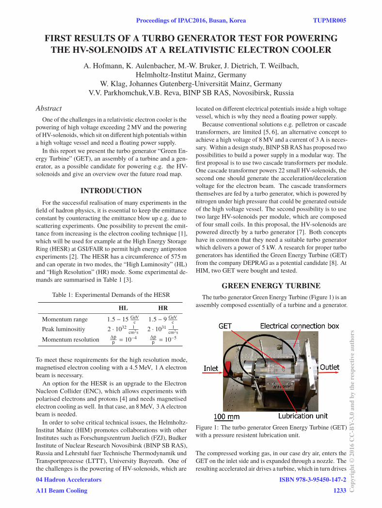
GREEN ENERGY TURBINEThe turbo generator Green Energy Turbine (Figure 1) is an
assembly composed essentially of a turbine and a generator.
Figure 1: The turbo generator Green Energy Turbine (GET)
with a pressure resistent lubrication unit.
The compressed working gas, in our case dry air, enters the
GET on the inlet side and is expanded through a nozzle. The
resulting accelerated air drives a turbine, which in turn drives
Proceedings of IPAC2016, Busan, Korea TUPMR005
04 Hadron Accelerators
A11 Beam Cooling
ISBN 978-3-95450-147-2
1233 Cop
yrig
ht©
2016
CC
-BY-
3.0
and
byth
ere
spec
tive
auth
ors

a generator. After the expansion, the air is diverted around
the generator and leaves the GET on the outlet side at normal
pressure. The generator is connected in delta configuration,
which generates three-phase current. The turbine and the
generator are supported by ball bearings, which need a small
amount of fresh lubricant in regular operation. Therefore
a pressure resistant lubrication unit is mounted at the GET,
which allows to inject small amounts of lubricant in regular
intervals. Our long term tests indicate that is necessary to
use 300 mm3 of fresh lubricant every 1000 hours. The used
lubricant is stored in special containers which are cleaned
during maintenance, so that the contamination of the driving
air is minimal. The GET itself should work for the typical
time for one production run at the HESR which is of the order
of nine month without maintenance. Further properties of
the GET are listed in Table 2. .
Table 2: Properties of the GET
Property ValuePower 5 kW
Revolution speed 35000 min−1
Pressure (in) 4 bar
Pressure (out) 1 bar
Mass Flow 4 m3
min
Pressure condensation point −20◦CVoltage phase to phase 263 V
Current 12 A
Norminal frequency 583 Hz
TEST MEASUREMENTS OF THE GETIn order to characterise the GET, different measurements
with two turbo generators were done at HIM. A sketch of the
test set-up is shown in Figure 2. A buffer tank is filled by a
Figure 2: Test set-up at HIM for characterising the GET.
Inside the buffer tanks heaters are installed for heating the
pressurised air before it enters the turbo generator. The
heaters are powered by the GET itself.
compressor, which consumes a power of 40 kW to generate
compressed air at 4 bar (abs) and an airflow of 4 m3
min. To re-
duce condensation (from the ambient air) after the expansion
within the turbo generator, the air in the buffer tank is heated.
In the regular operation, the turbo generator is located within
a high voltage vessel at a pressure of 10 bar (abs). For tests,
the GET is mounted in a pressure tank, which can be filled
with air up to 11 bar (abs), as load resistors are used. Figure
3 shows the measurement of the DC power as function of
the revolution speed for both tested GETs and two different
loads.
Figure 3: Measurement of the DC power as function of the
revolution speed for both GET and different loads.
The measurements show that it is possible to generate the
needed power of 5 kW within the limits of the GET, but the
characteristics of both turbo generators differ a little. The
outlet temperature of the air for a load of 25Ω is presented
in Figure 4.
Figure 4: Air outlet temperature as function of the DC power
for a load of 25Ω. The temperature drop of the air after the
expansion is in the order of 50 K.
For both turbo generators, the drop of the air temperature is
in the range of (50 ± 5)◦C, which means that the expanded
gas could in principle be used for the cooling of the HV-
solenoids.
Another important point is the pressure resistance of the
turbo generator. It must be ensured that no sulphur hexafluo-
ride may penetrate into the turbo generator. To test whether
gas can penetrate into the GET, the pressure in the pressure
tank was raised to 10 bar (abs). Because of leaking instru-
TUPMR005 Proceedings of IPAC2016, Busan, Korea
ISBN 978-3-95450-147-2
1234Cop
yrig
ht©
2016
CC
-BY-
3.0
and
byth
ere
spec
tive
auth
ors
04 Hadron Accelerators
A11 Beam Cooling
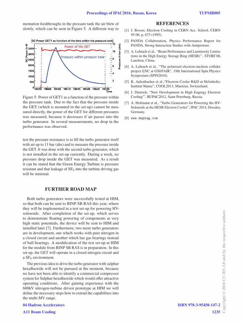
mentation feedthroughs in the pressure tank the air blew of
slowly, which can be seen in Figure 5. A different way to
Figure 5: Power of GET1 as a function of the pressure within
the pressure tank. Due to the fact that the pressure inside
the GET (which is mounted in the set-up) cannot be mea-
sured directly, the power of the GET for different pressures
was measured, because it decreases if air passes into the
turbo generator. In several measurements, no drop in the
performance was observed.
test the pressure resistance is to fill the turbo generator itself
with air up to 11 bar (abs) and to measure the pressure inside
the GET. It was done with the second turbo generator, which
is not installed in the set-up currently. During a week, no
pressure drop inside the GET was measured. As a result
it can be stated that the Green Energy Turbine is pressure
resistant and that leakage of SF6 into the turbine driving gas
will be minimal.
FURTHER ROAD MAP
Both turbo generators were successfully tested at HIM,
so that both can be sent to BINP SB RAS this year, where
they will be implemented in a test set-up for powering HV-
solenoids. After completion of the set-up, which serves
to demonstrate floating powering of components at very
high static potentials, the device will be sent to HIM and
installed later [7]. Furthermore, two more turbo generators
are in development, one which works with pure nitrogen in
a closed circuit and another which has gas bearings instead
of ball bearings. A modification of the test set-up at HIM
for the module from BINP SB RAS is in preparation. In this
set-up, the GET will operate in a closed nitrogen circuit and
a SF6 environment.
The previous idea to drive the turbo generator with sulphur
hexafluoride will not be pursued at the moment, because
we have not been able to identify a commercial compressor
system for Sulphur hexafluoride which would offer attractive
operating conditions. After gaining experience with the
600kV nitrogen-turbine driven prototype at HIM we will
define the necessary steps how to extend the capabilities into
the multi MV range.
REFERENCES[1] J. Bosser, Electron Cooling in CERN Acc. School, CERN
95-06, p, 673 (1995).
[2] PANDA Collaboration, Physics Performance Report for
PANDA, Strong Interaction Studies with Antiprotons.
[3] A. Lehrach et al., “Beam Performance and Luminosity Limita-
tions in the High Energy Storage Ring (HESR)” , STORI’08,
Lanzhou, China.
[4] A. Lehrach et al., “The polarized electron-nucleon collider
project ENC at GSI/FAIR", 19th International Spin Physics
Symposium (SPIN2010).
[5] K. Aulenbacher et al.,“Electron Cooler R&D at Helmholtz-
Insttitut Mainz”, COOL2013, Muerren, Switzerland.
[6] J. Dietrich, “New Development in High Engergy Electron
Cooling”’, RUPAC2012, Saint Peterburg, Russia.
[7] A. Hofmann et al., “Turbo Generators for Powering the HV-
Solenoids at the HESR Electron Cooler”, IPAC 2014, Dresden,
Germany.
[8] www.deprag.com
Proceedings of IPAC2016, Busan, Korea TUPMR005
04 Hadron Accelerators
A11 Beam Cooling
ISBN 978-3-95450-147-2
1235 Cop
yrig
ht©
2016
CC
-BY-
3.0
and
byth
ere
spec
tive
auth
ors