First in situ measurement of soil thermal response in ... · First in situ measurement of soil...
10
First in situ measurement of soil thermal response in Guayaquil, Ecuador G. Soriano 1 , R. Villanueva 2 , I. Gonzalez 2 , K. Lopez 1 & M. Cornejo 1 1 Escuela Superior Politecnica del Litoral ESPOL, Ecuador 2 Instituto Nacional de Eficiencia Energetica y Energia Renovable INER, Ecuador Abstract The paper presents the results of the first experimental measurement of soil thermal properties in Guayaquil, Ecuador. The experimental point is located at UTM (0622853/09755713) and the test was carried out during the Ecuadorian dry season. This location is geologically composed of sediments of estuarine-deltaic nature from River Guayas. A boring of 113 mm diameter and 50 m deep was drilled to perform the test. The experiment consists of heating and water pumping during a period of between 48 and 72 hours. The power input to the system is 2746.03 W which heats a water flow of 1.36 m3/h, corresponding to a value of 54.92 W/m. A linear source model was used to obtain the thermal conductivity and diffusivity of the soil. In order to reduce errors in the calculations it is important to allow the system to reach steady state ݐ ଶ మ ఈ . In our case steady state was reached after the first 12 hours of measurement. Thermal conductivity of the soil was calculated to be 1.310–1.312 W/m K, thermal diffusivity between 0.017–0.046 m2/day. The core material of the drilling was recovered and used for a lithological, mineralogical and geotechnical analysis of the samples using X-ray diffraction, optical microscopy, grain size analysis. Silts containing 45.3% illite- motmorillonite and 32.1% anortite, 18.2% cuarzo and 4.4% amorphous minerals. Mineralogy in sand is cuarzo and plagioclasa anortite type. Finally, an assessment of the suitability of the soil for the use of underground heat exchangers with the potential of replacing cooling towers in buildings’ climatization systems is performed. Keywords: geothermal system, thermal properties, lithological characteristics. Energy and Sustainability VI 327 www.witpress.com, ISSN 1743-3541 (on-line) WIT Transactions on Ecology and The Environment, Vol 195, © 2015 WIT Press doi:10.2495/ESUS150281
Transcript of First in situ measurement of soil thermal response in ... · First in situ measurement of soil...

First in situ measurement of soil thermal response in Guayaquil, Ecuador
G. Soriano1, R. Villanueva2, I. Gonzalez2, K. Lopez1 & M. Cornejo1 1Escuela Superior Politecnica del Litoral ESPOL, Ecuador 2Instituto Nacional de Eficiencia Energetica y Energia Renovable INER, Ecuador
Abstract
The paper presents the results of the first experimental measurement of soil thermal properties in Guayaquil, Ecuador. The experimental point is located at UTM (0622853/09755713) and the test was carried out during the Ecuadorian dry season. This location is geologically composed of sediments of estuarine-deltaic nature from River Guayas. A boring of 113 mm diameter and 50 m deep was drilled to perform the test. The experiment consists of heating and water pumping during a period of between 48 and 72 hours. The power input to the system is 2746.03 W which heats a water flow of 1.36 m3/h, corresponding to a value of 54.92 W/m. A linear source model was used to obtain the thermal conductivity and diffusivity of the soil. In order to reduce errors in the calculations it is
important to allow the system to reach steady state . In our case steady
state was reached after the first 12 hours of measurement. Thermal conductivity of the soil was calculated to be 1.310–1.312 W/m K, thermal diffusivity between 0.017–0.046 m2/day. The core material of the drilling was recovered and used for a lithological, mineralogical and geotechnical analysis of the samples using X-ray diffraction, optical microscopy, grain size analysis. Silts containing 45.3% illite-motmorillonite and 32.1% anortite, 18.2% cuarzo and 4.4% amorphous minerals. Mineralogy in sand is cuarzo and plagioclasa anortite type. Finally, an assessment of the suitability of the soil for the use of underground heat exchangers with the potential of replacing cooling towers in buildings’ climatization systems is performed. Keywords: geothermal system, thermal properties, lithological characteristics.
Energy and Sustainability VI 327
www.witpress.com, ISSN 1743-3541 (on-line) WIT Transactions on Ecology and The Environment, Vol 195, © 2015 WIT Press
doi:10.2495/ESUS150281

1 Introduction
The measurement of soil thermal properties in Ecuador is a new local experience. Experiences in other countries were performed with the purpose of using soil as source or sink of heat [1]. This thermal properties comprises temperature, thermal conductivity, resistivity and diffusivity. Its knowledge would give us insight of the potential thermal use of soil [2, 3]. The city of Guayaquil is located in tropical zone, experiencing high values of temperature and relative humidity most of the year [4]. As a consequence, mechanical systems to cool buildings a subject to great strains. Traditional systems using cooling towers reach their limits with respect to energy efficiency. The maximum refrigeration loads typically coincide with the maximum temperature of the day worsening the problem. Besides, a cooling tower contributes to water consumption and to the urban heat island problem diminishing the performance of the others cooling mechanical systems. Performing the in situ thermal response test is the most reliable method of estimating thermal properties of the soil alongside geotechnical and lithological characterization [5]. This test requires a vertical boring of heights ranging from 40 to 80 m where a U tube for water circulation is placed. The site selection has considered the type of soil from geological surveys of the city, as well as easiness of access and availability of basic services. The location selected was the exteriors of Centro Civico Eloy Afaro (UTM 0622853/09755713), a centric place which is representative of type of soil in most of the city.
Nomenclature
cp heat capacity (J kg-1 K-1) Greek characters d pipe diameter (mm) α thermal diffusivity (m2 s-1) D borehole diameter (mm) k thermal conductivity (W m-1 K-1) SubscriptsL depth (m) b borehole m fluid mass flow rate (kg s-1) f fluid Q heat transfer rate (W) g grout R thermal resistance (m K W-1) i inside t time (s) o outside T temperature (K) p pipe s soil Dimensionless numbers Pr Prandtl number Re Reynolds number
2 Methodology
Measurement of thermal diffusivity is performed with the known method of a geothermal probe buried vertically [6–8]. Inside the probe, water is circulated controlling its flow and temperature. By controlling the inlet and outlet
328 Energy and Sustainability VI
www.witpress.com, ISSN 1743-3541 (on-line) WIT Transactions on Ecology and The Environment, Vol 195, © 2015 WIT Press

temperature, and the time lapse, it is possible to determine the value of thermal conductivity. Three methods of properties determination were used. Materials extracted from the drilling were subject to laboratory analysis, and with the use of databases the average value of properties were determined. Also an analytical heat transfer model is used. Results are corroborated with the use of a commercial geothermal system design software [9]. The analytical model commonly used in this type of tests is the lineal source heat transfer model where the heat rate and temperature are constants. The thermal conductivity can be obtained with Equation (1) [10].
.
(1)
where L is the depth of the borehole; Rf, Rp and Rg are the thermal resistances of the fluid, piping, and grout respectively and are determined by equations (2), (3) and (4).
, (2)
ln ,
, (3)
ln, √
(4)
where n is the number of pipes and hf is the convective heat transfer coefficient for the internal flow in the piping which could be calculated using Dittus-Boelter relation (equation (5)).
0.023,
. . (5)
The value of ΔT in the linear source model is the difference between the mean temperature of the circulating fluid and the soil temperature without any perturbation. Nevertheless, it is worth mentioning that this equation is not always valid due to changes in calorific capacity of several elements of the borehole, which gave a strong influence in the thermal field. The effective thermal resistance of the soil Rs(t) could be determined dividing the difference between the mean temperature of the fluid (Tf) and that of the soil without perturbation (Tg) over the heat transfer rate per unit length as expressed in equation (6).
(6)
The value of thermal resistence is a function of time. The steady state value of the thermal resistance could be used to estimated the length of the U tube for a given thermal load (1) [11].
Energy and Sustainability VI 329
www.witpress.com, ISSN 1743-3541 (on-line) WIT Transactions on Ecology and The Environment, Vol 195, © 2015 WIT Press

3 Installation
The drilling method used for the borehole was rotating percussion with core recovery based in the combination of the spinning of the cutting tool made of tungsten carbide with the simultaneous pressure exerted by the machine at the bottom of the drilling. During the forward movement, the drilling operation is recovering a continuous cylindrical sample of the soil through the whole depth of the borehole. At the end, the borehole has a depth L = 50 m and a diameter D = 113 mm. Later, a U tube high density polyethylene piping is placed inside the borehole in order to perform the test. This pipe has diameter d = 19 mm and a pressure resistance of 0.724 MPa (105 psi). Finally, the borehole is filled with a grout composed of cement and bentonite in order to avoid filtrations and to fix the piping [11, 12]. At the end of the pipe two metallic elbow accessories form the U for the return of the fluid (a schematic is presented in Figure 1).
Figure 1: Schematic of experimental setup with the U pipe and the thermal response test equipment.
The thermal conductivity of the grout and piping is low due to the type of materials used. However, the large available surface facilitates heat transfer and avoids an excessive heating of the soil by dissipating heat in a radius of enough length. It takes two weeks from pouring the grouting until performing the test in order to allow the dissipation of the heat from the curing of the grout [13]. The thermal response test equipment heats the water flow through a series of electrical resistances, which allows selection of heating power. The equipment
330 Energy and Sustainability VI
www.witpress.com, ISSN 1743-3541 (on-line) WIT Transactions on Ecology and The Environment, Vol 195, © 2015 WIT Press
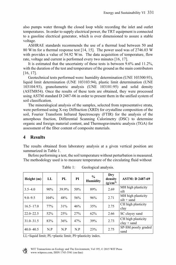
also pumps water through the closed loop while recording the inlet and outlet temperatures. In order to supply electrical power, the TRT equipment is connected to a gasoline electrical generator, which is over dimensioned to assure a stable voltage. ASHRAE standards recommends the use of a thermal load between 50 and 80 W/m for a thermal response test [14, 15]. The power used was of 2746.03 W with provides a value of 54.92 W/m. The data acquisition of temperature, flow rate, voltage and current is performed every two minutes [16, 17]. It is estimated that the uncertainty of these tests is between 9.6% and 11.2%, with the duration of the test and temperature of the ground as the main contributors [16, 17]. Geotechnical tests performed were: humidity determination (UNE 103300:93), liquid limit determination (UNE 103103:94), plastic limit determination (UNE 103104:93), granolumetric analysis (UNE 103101:95) and solid density (ASTM854). Once the results of these tests are obtained, they were processed using ASTM standard D 2487-06 in order to present them in the unified system of soil classification. The mineralogical analysis of the samples, selected from representative strata, were performed using X-ray Diffraction (XRD) for crystalline composition of the soil, Fourier Transform Infrared Spectroscopy (FTIR) for the analysis of the amorphous fraction, Differential Scanning Calorimetry (DSC) to determine organic and foreign material content, and Thermogravimetric analysis (TGA) for assessment of the fiber content of composite materials.
4 Results
The results obtained from laboratory analysis at a given vertical position are summarized in Table 1. Before performing a test, the soil temperature without perturbation is measured. The methodology used is to measure temperature of the circulating fluid without
Table 1: Geological analysis.
Height (m) LL PL PI %
Humidity
Dry density (g/cm3)
ASTM: D 2487-69
3.5–4.0 90% 39.9% 50% 89% 2.69 MH high plasticity silt
9.0–9.5 104% 48% 56% 96% 2.71 MH high plasticity silt + sand
16.5–17.0 77% 31% 46% 35% 2.75 CH high plasticity clay
22.0–22.5 52% 25% 27% 62% 2.66 SC clayey sand
31.0–31.5 83% 36% 47% 39% 2.73 CH high plasticity clay + sand
40.0–40.5 N.P N.P N.P 23% 2.75 SP-SM poorly graded sand
LL=liquid limit; PL=plastic limit; PI=plasticity index.
Energy and Sustainability VI 331
www.witpress.com, ISSN 1743-3541 (on-line) WIT Transactions on Ecology and The Environment, Vol 195, © 2015 WIT Press

any thermal load from the TRT equipment and comparing the inlet and outlet temperature for approximately 15 minutes. The test begins after the temperature of the fluid reaches the temperature of the soil without perturbation. During the test, all temperatures are recorded until the fluid reaches a steady state condition between two to three days, which depends on the thermal load and length of the piping. During the test, the liquid flow as well as the thermal load are kept constant. Data obtained could be observed in figure 2 for the outlet temperature and figure 3 for the thermal load supplied to the system.
Figure 2: Experimental set up.
Figure 3: Thermal Response Test (TRT).
306
308
310
312
314
316
318
320
322
324
0 5 10 15 20 25 30 35 40 45 50
Temperature (K)
Time (h)
Outlet Temp
Inlet Temp
Mean Temp
332 Energy and Sustainability VI
www.witpress.com, ISSN 1743-3541 (on-line) WIT Transactions on Ecology and The Environment, Vol 195, © 2015 WIT Press

Figure 4: Thermal load for fluid heating.
It can be considered that thermal load has been kept stable during the test. The data obtained from the measurement with the thermal response equipment are presented in Table 2.
Table 2: Measurement results.
T mean T inlet mean
T outlet mean
Mean flow rate T soil Thermal
load
321.37 K 322.21 K 320.53 K 4.592x10⁻⁴ m3/s 302.15 K 2746.03 W
5 Analysis
The laboratory analysis has determined the mineralogical composition of the materials obtained from the borehole drilling. Table 3 shows a summary of the mineralogical layers with a weighted thermal conductivity from bibliography and relative composition The computation of thermal properties via experimental data is performed through a commercial software for the design for ground thermal systems as well as from linear source methodology [9]. In order to perform the analysis, the first twelve hours of data are discarded to avoid working on the transient regime as shown in figure 4. Table 4 presents a summary of the main results in which thermal conductivity of the soil is 1.123 W/m-K and Resistivity is 0.337 m-K/W by the linear source method, both results were corroborated with the use of a modeling software.
2400
2500
2600
2700
2800
2900
3000
0 10 20 30 40 50
Heater Power (W
)
Time (h)
Energy and Sustainability VI 333
www.witpress.com, ISSN 1743-3541 (on-line) WIT Transactions on Ecology and The Environment, Vol 195, © 2015 WIT Press

Table 3: Mineralogical soil composition percentage and thermal conductivity.
Material Relative
composition
Thermal conductivity
(W/m K) CH high plasticity clay 4% 0.048
CH high plasticity clay + sand 10% 0.121
MH high plasticity silt 16% 0.193
ML low plasticity silt with sand 14% 0.170
Filler material 2% 0.035
SC clayey sand 24% 0.293
SP-SM poorly graded sand 30% 0.360
Total thermal conductivity 1.22
Figure 5: Linear source model from the first in situ determination of soil properties in Guayaquil, Ecuador.
∆T(t) = 3.3977x + 308.11
316
317
318
319
320
321
322
1 2 3 4 5
T f(t)‐T g
(K)
ln(t)
334 Energy and Sustainability VI
www.witpress.com, ISSN 1743-3541 (on-line) WIT Transactions on Ecology and The Environment, Vol 195, © 2015 WIT Press

Table 4: Summary of thermal properties obtained from the first in situ thermal response test in Ecuador.
Software Linear source method Ks (W/m K) αs (m2/day) ks (W/m K) αs (m2/day)
1.130 0.012 1.123 0.012
6 Conclusions
This research provided the results of the first in situ thermal response test of soil in Ecuador with a value of 1.130 W/m-K and a soil resistivity of 0.33 m-K/W. Different methods to compute the thermal properties of the soil produced congruent and similar results, which validates the methodology. It is considered that in situ measurement is the most precise method of obtaining thermal properties while the analysis and averaging of properties of mineralogical layers an alternative methodology. The measurement was performed on the dry season, it is expected that results will change with season mostly due to the water content of the soil. The average temperature of the soil through the 50 m of the borehole is 29°C. This temperature is considered high in comparison of results obtained in other places. Despite this temperature, it is not discarded to take advantage of the soil as heat sink in cooling processes in buildings, due that this temperature is still below air temperature during daylight and with little to no change during the day despite conditions in the atmosphere.
Acknowledgements
The authors acknowledge the support of Secretaria de Educacion Superior, Ciencia, Tecnologia e Innovacion of the Republic of Ecuador for supporting this project.
References
[1] P. Roth, A. Georgiev, A. Busso and E. Barraza, “First in situ determination of ground and borehole thermal properties in Latin America”, Renewable Energy, vol. 29, pp. 1947–1963, 2004.
[2] A. Hepbasli and Y. Kalinci, “A review of heat pump water heating systems”, Renewable and Sustainable Energy Reviews, vol. 13, pp. 1211–1229, 2009.
[3] C. A. De Swardt and J. P. Meyer, “A performance comparison between an air-source and a ground-source reversible heat pump”, International Journal of Energy Research, vol. 25, pp. 899–910, 2001.
[4] “Boletín Climatológico Anual”, Instituto Nacional de Meteorología e Hidrología (INAMHI), 2014.
Energy and Sustainability VI 335
www.witpress.com, ISSN 1743-3541 (on-line) WIT Transactions on Ecology and The Environment, Vol 195, © 2015 WIT Press

[5] H. J. Witte, G. J. van Gelder and J. D. Spitler, “In Situ measurement of Ground Thermal Conductivity: The Dutch Perspective”, ASHRAE Transactions, vol. 108, nº 1, 2002.
[6] A. Choudary, “An approach to determine the thermal conductivity and diffusivity of a rock in situ”, Oklahoma State University (OSU), 1976.
[7] P. Mogensen, “Fluid to Duct Wall Heat Transfer in Duct System Heat Storages”, Proc. International Conference on Subsurface Heat Storage in Theory and Practice, pp. 652–657, 1983.
[8] C. Eklöf and S. Gehlin, “A Mobile Equipment for Thermal Response Test”, Lulea University of Technology (LuTH), Vol. 1 MSc-thesis:198E, p. 62, 1996.
[9] “Ground Loop Design”, Gaia Geothermal, LLC., 2014. [10] M. A. Boukli Hacene, S. Amara and N. E. Chabane Sar, “Analysis of the
first thermal response test in Algeria”, Journal of Thermal Analysis & Calorimetry, vol. 107, pp. 1363–1369, 2011.
[11] M. H. Sharqawy, S. Said, E. Mokheimer, M. Habib, H. Badr and N. Al-Shayea, “First in situ determination of the ground thermal conductivity for borehole heat exchanger applications in Saudi Arabia”, Renewable Energy, vol. 34, pp. 2218–2223, 2009.
[12] M. Allan and A. Philippacopoulos, “Properties and performance of cement-based grouts for geothermal heat pump applications”, 1999.
[13] M. I. Sanchez de Rojas, M. Frías and J. Rivera, “Estudios sobre el calor de hidratación desarrollado en morteros con materiales puzolánicos: naturales y subproductos industriales”, Materiales de Construcción, vol. 50, pp. 39–48, 2000.
[14] J. Saqib, D. S. Jeffrey and F. Per , “An Experimental Investigation of the Accuracy of Thermal Response Tests Used to Measure Ground Thermal Properties”, ASHRAE Transactions, 2011.
[15] ASHRAE Handbook – HVAC Applications, Chapter 34 Geothermal Energy, 2011.
[16] C. A. Martin and S. P. Kavanaugh, Ground thermal conductivity testing-controlled site analysis, ASHRAE Transactions, 2002, p. 945.
[17] J. Spitler, C. Yavuzturk and S. Rees, “In Situ Measurement of Ground Thermal Properties”, Proceedings of Terrastock, 2000.
336 Energy and Sustainability VI
www.witpress.com, ISSN 1743-3541 (on-line) WIT Transactions on Ecology and The Environment, Vol 195, © 2015 WIT Press