Firoz all india radio ppt
20
ON Poata C-Road, Jodhpur (Rajasthan) Presented to : Ms. Laxmi Chaudhary Presented By : Firoz Tak 7 th sem, ECE
-
Upload
parikshit-kuldiya -
Category
Engineering
-
view
72 -
download
10
Transcript of Firoz all india radio ppt

ON
Poata C-Road, Jodhpur (Rajasthan)
Presented to :Ms. Laxmi Chaudhary
Presented By :Firoz Tak7th sem, ECE

• Radio is the transmission of signals by modulation of electromagnetic waves with frequencies below those of visible light.
• Radio is based on wireless communication or setellite communication.
• In this era of technology due to need of wireless communication, A national service was planned and developed by the Prasar Bharati Broadcasting Corporation of India.

The first license granted for transmitting a broadcast was given on February 23, 1922. The Radio Club of Calcutta was the first radio club to start functioning in Nov-1924
The Government run broadcasting set up was called the India State Broadcasting Service (ISBS) which is then turned into AIR (All India Radio) in June 1936.
The introduction of the commercial channel ‘Vividh Bharti’ in October 1957 increased the interest and popularity of radio.
AIR today has a network of 232 broadcasting centres with 149 medium frequency(MW), 54 high frequency (SW) and
171 FM transmitters.The coverage is 91.79% of the area serving 99.14% of the people.C

TransmittingA radio wave carries information signal; Signals are converted into electrical signals. A carrier wave is then produced from the modulation. The wave is then amplified, and sent to the antenna that then converts signal into an E.M. wave.
ReceivingAn antenna on receiving the signal send it to the receiver this then converts the electrical signal sends it to the amplifier either a speaker/headphones jack this is
then converted into a sound wave.

• Studio Centre
• Broadcast Studio
• Mixing
• Control Room

Recording Room
Dubbing Room
Loud Speakers
Headphones


Studio transmitter link equipment in 1.5 GHz frequency band can be used for transmission of signal music channel (STL-O1). STL link consist of two terminal i.e. one receiver and one transmit the music program from AIR.
Receiver terminal consist of only receiver modules required to receive the studio program and then this music is given to AIR transmitter. Both transmitter and receiver terminals are with standby modules the switch over operation to standing module is automatic without any time Delay

CHARACTERISTICS The studio transmitter link equipment satisfy highly specific requirement such as....1.High operation reliability.2.High quality transmission.3.Use of synthesizer for selection of oscillator frequency. Integrated operation and faults diagnosis.4.Transmitter and receiver local monitoring facilities. Simple Direct and easy access to channel signal easy replacement of subunits on site.5.No periodically maintenance necessary.

It has following component 15 in different rack 1.Cathode ray oscilloscope to see the audio signal which is received From the studio and is now modulated by transmitter. (model of Tektronix tds 3032 300 mhz).2.Monitoring amplifier to amplify the signal received.3.Hooter to alert before starting the transmission.4.Modulations monitor to monitor the modulated signal. There is a
Small receiver located at hpt soorsagar which receives the Modulated signal which is to be transmitted and fed to the program Input rack's modulation monitor.

5. Patch panel to terminate circuits and facilities provided for Interconnecting between circuits by means of jacks and plugs. It Consists of receptacles into which jumpers can be inserted.6. Limiters to limit the modulated signal.7. Dual output regulated power supply. 8. Equalizer a network usually adjustable, which corrects the Transmission frequency characteristics of circuit.
• AC POWER SUPPLY
• DC POWER SUPPLY

FM broadcasts were introduced in Madras in 1977 and later at Jalandhar in 1992, but it was only in 1993 when slots came to be leased to private companies.
On August 15, 1993 a Frequency Modulation (FM) Channel was launched in Bombay, with nine hours of radio which sloats was leased to private producers like Times FM, radiostar and Radio Midday.
In FM Phase II some 338 frequencies were offered of which about 237 were sold.

Here is an example of both FM modulation and AM modulation you can see from the image that AM is much looser than the FM signal meaning that less data can be sent at one time as it isn’t compressed. The reason for the difference in sound quality as a lower bitrate must be sent across the wave.
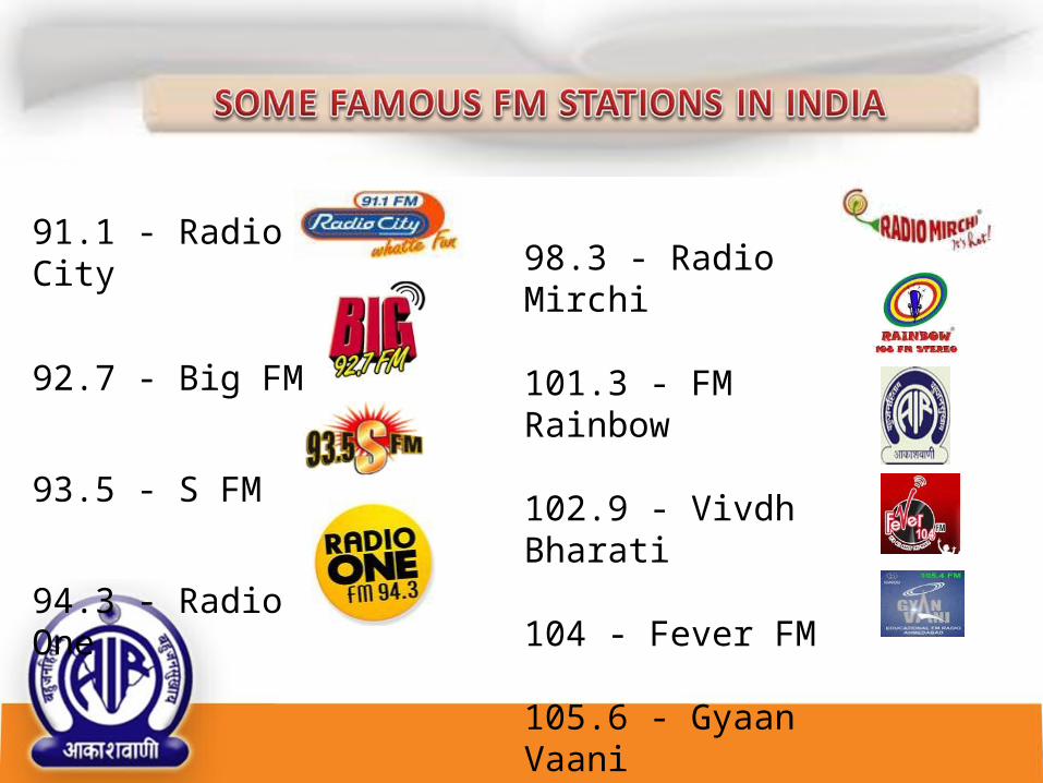
91.1 - Radio City
92.7 - Big FM
93.5 - S FM
94.3 - Radio One
98.3 - Radio Mirchi
101.3 - FM Rainbow
102.9 - Vivdh Bharati
104 - Fever FM
105.6 - Gyaan Vaani

o This is only means which can provide multi access two way communication.o The cost of transmitting information through satellite is independent of distance involved.o Satellite can be used for two way communication or broadcast purpose with the covered area.o Satellites are capable of handling very high bandwidth.o It is possible to provide large coverage using satellite. For example Geostationary satellite can cover about 42% of earth surface using global beam.


Queries…If any…