Firefly Optimization Based Control Strategies for …Firefly Optimization Based Control Strategies...
12
International Journal on Electrical Engineering and Informatics - Volume 11, Number 4, December 2019 Firefly Optimization Based Control Strategies for Combined Load Frequency Control and Automatic Voltage Regulation for Two-Area Interconnected Power System A. K. Sahani, Utkarsh Raj, Ravi Shankar, and R. K. Mandal Department of Electrical Engineering, National Institute of Technology Patna Patna, India-800005 Abstract: In this research work the combined Load Frequency Control (LFC) and Automatic Voltage Regulation (AVR) of a two-area interconnected power system has been considered. Each control area consists of linearized model of thermal and hydropower system. PID controller has been used as the secondary controller for the combined LFC-AVR of the proposed system. A powerful meta-heuristic algorithm Firefly optimisation technique is used for the optimisation of the proposed controller. Comparison of the system dynamics with and without proposed controller is investigated to show effectiveness of the proposed control scheme. Also, a comparison of the proposed control scheme with other popular meta-heuristic techniques shows the superiority of the proposed control scheme. Moreover, small signal stability analysis of the proposed system has been done using the state space representation of the proposed system. Keywords: AVR, FA, LFC, PID, PSO. 1. Introduction Maintenance of reliable and quality power is becoming an ever-increasing challenge in this modern and dynamic world. Generally, when the load side demand changes, a breach in the frequency and voltage subsequent to the load is also witnessed. for the regulation of power frequency load frequency control (LFC) is used, while the machine power output is controlled by the automatic voltage regulator (AVR) by regulating the voltage [1]. Most of the research in literature is generally focussed on the LFC and AVR problem separately. But, when demand changes, there is a deviation in both the frequency and voltage simultaneously from their nominal values respectively. Thus, there is a need to investigate on the combined LFC-AVR problem. Chandrakala et al. used simulated annealing based PID controller for the combined LFC-AVR of the two-area multi-source power system [2]. Qin et al. have used non-linear programming for the AVR of power systems with limited continuous voltage control capability to minimize operational cost [3]. Abd-Alazim et al. have used firefly algorithm based PI controller for LFC of a system including PV grid [4]. Guha et al. have used symbiotic organism search based PID controller for the LFC of a two area thermal reheat system [5]. Mostly researchers have focussed on single, two or three area systems having conventional or non-conventional generation sources to study the LFC problem in different environments [6][7][8][9][10]. Essentially, in this research work the authors have tried to investigate the LFC and AVR problem in a combined manner since very few literature are available in this field. Various types of controller are discussed in the literature. Conventional controllers are generally preferred by both the researchers and the industry due to their low cost and simple construction. Conventional controllers like integral (I), proportional-integral (PI) and proportional-integral-derivative (PID) are readily used in the literature [11][12][13]. A conventional controller performs satisfactorily only when its parameters are optimised according to the system conditions. For this both manual and automatic techniques are available in literature, though automatic techniques are generally preferred. Intelligent techniques based on modern optimisation algorithms are generally used for the tuning of controller parameters according to the system requirements. Some of the intelligent algorithms used in the literature for the tuning of controller parameters are genetic algorithm (GA) [14], particle swarm Received: March 5 th , 2018. Accepted: November 18 th , 2019 DOI: 10.15676/ijeei.2019.11.4.8 746
Transcript of Firefly Optimization Based Control Strategies for …Firefly Optimization Based Control Strategies...

International Journal on Electrical Engineering and Informatics - Volume 11, Number 4, December 2019
Firefly Optimization Based Control Strategies for Combined Load
Frequency Control and Automatic Voltage Regulation for Two-Area
Interconnected Power System
A. K. Sahani, Utkarsh Raj, Ravi Shankar, and R. K. Mandal
Department of Electrical Engineering, National Institute of Technology Patna
Patna, India-800005
Abstract: In this research work the combined Load Frequency Control (LFC) and Automatic
Voltage Regulation (AVR) of a two-area interconnected power system has been considered.
Each control area consists of linearized model of thermal and hydropower system. PID controller
has been used as the secondary controller for the combined LFC-AVR of the proposed system.
A powerful meta-heuristic algorithm Firefly optimisation technique is used for the optimisation
of the proposed controller. Comparison of the system dynamics with and without proposed
controller is investigated to show effectiveness of the proposed control scheme. Also, a
comparison of the proposed control scheme with other popular meta-heuristic techniques shows
the superiority of the proposed control scheme. Moreover, small signal stability analysis of the
proposed system has been done using the state space representation of the proposed system.
Keywords: AVR, FA, LFC, PID, PSO.
1. Introduction
Maintenance of reliable and quality power is becoming an ever-increasing challenge in this
modern and dynamic world. Generally, when the load side demand changes, a breach in the
frequency and voltage subsequent to the load is also witnessed. for the regulation of power
frequency load frequency control (LFC) is used, while the machine power output is controlled
by the automatic voltage regulator (AVR) by regulating the voltage [1]. Most of the research in
literature is generally focussed on the LFC and AVR problem separately. But, when demand
changes, there is a deviation in both the frequency and voltage simultaneously from their nominal
values respectively. Thus, there is a need to investigate on the combined LFC-AVR problem.
Chandrakala et al. used simulated annealing based PID controller for the combined LFC-AVR
of the two-area multi-source power system [2]. Qin et al. have used non-linear programming for
the AVR of power systems with limited continuous voltage control capability to minimize
operational cost [3]. Abd-Alazim et al. have used firefly algorithm based PI controller for LFC
of a system including PV grid [4]. Guha et al. have used symbiotic organism search based PID
controller for the LFC of a two area thermal reheat system [5]. Mostly researchers have focussed
on single, two or three area systems having conventional or non-conventional generation sources
to study the LFC problem in different environments [6][7][8][9][10]. Essentially, in this research
work the authors have tried to investigate the LFC and AVR problem in a combined manner
since very few literature are available in this field.
Various types of controller are discussed in the literature. Conventional controllers are
generally preferred by both the researchers and the industry due to their low cost and simple
construction. Conventional controllers like integral (I), proportional-integral (PI) and
proportional-integral-derivative (PID) are readily used in the literature [11][12][13]. A
conventional controller performs satisfactorily only when its parameters are optimised according
to the system conditions. For this both manual and automatic techniques are available in
literature, though automatic techniques are generally preferred. Intelligent techniques based on
modern optimisation algorithms are generally used for the tuning of controller parameters
according to the system requirements. Some of the intelligent algorithms used in the literature
for the tuning of controller parameters are genetic algorithm (GA) [14], particle swarm
Received: March 5th, 2018. Accepted: November 18th, 2019
DOI: 10.15676/ijeei.2019.11.4.8
746

optimisation (PSO) [15], quasi-oppositional harmonic search (QOHS) algorithm [16], fruitfly
optimisation algorithm (FOA) [17], bacteria foraging algorithm (BFA) [18], whale optimisation
algorithm (WOA) [19] and interactive search algorithm (ISA) [20].
The main highlights of the current research work are:
a) Combined LFC-AVR model of a two-area interconnected hybrid power system.
b) Investigate the effect of AVR loop in LFC of the proposed system.
c) Investigate the effect of the secondary controller on the dynamics of the system.
d) Investigate the small signal stability of the proposed model.
e) Implementation of the efficacy of FireFly Algorithm (FA) and Particle Swarm Optimization
(PSO) for the optimization of the proposed controller.
f) Comparison of the effects of FA-based PID controller and PSO-tuned PID controller on the
dynamics of the proposed model to show the dominance of the proposed controller.
g) Comparison of convergence profile of proposed scheme with PSO, WOA and ISA based
control scheme
The rest of this research work is divided into the subsequent parts. Section-2 discusses the
detailed modelling of the combined LFC-AVR model of a two-area interconnected power
system. Section-3 deals with the FA technique and the formulation of the objective function.
Section-4 investigates the small signal stability analysis of the proposed model. Section-5 gives
the simulation results and analysis of the proposed model. Finally, section-6 concludes the
present research work.
2. Integrated LFC-AVR model for multi-area power system
In this research work, a two-area system, each having a thermal and a hydro system, is
considered. The LFC-AVR loop has been integrated into the proposed model. Though the loop
acts slowly, it helps in minimizing the system disturbance. The thermal system is composed of
the hydraulic amplifier, speed governor, boiler and non-reheat turbine while the hydro system
comprises of the hydro-speed governor and hydro turbine. When a disturbance occurs in the
system, the speed governor adjusts the input of the turbine so as to compensate the extra demand.
The transfer function for the governor can be written as:
𝛥𝑃𝐺 = 𝛥𝑃𝑅𝑒 𝑓1 −1
𝑅1𝛥𝑓1 (1)
Also to fulfill the demand, the boiler transmits the control action to the turbine control valves
by sensing the deviation in the steam-flow and pressure drum. The model of the boiler system is
shown in Figure 1.
k3
k2
BsC
1 ( )( )1 1
(1 0.1 )
IB IB RB
RB
K sT sT
s sT
+ +
+
1
DsT
F
e
sT
−
+
ExRP
k1
Figure 1. Detailed Model of the Boiler System
A. K. Sahani, et al.
747
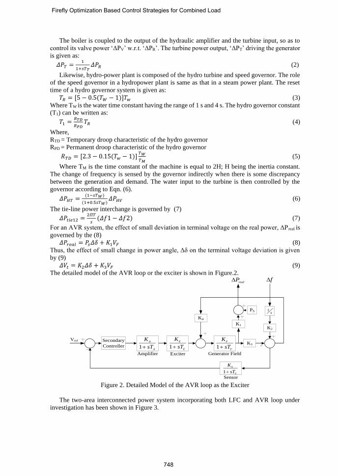
The boiler is coupled to the output of the hydraulic amplifier and the turbine input, so as to
control its valve power ‘ΔPV’ w.r.t. ‘ΔPR’. The turbine power output, ‘ΔPT’ driving the generator
is given as:
𝛥𝑃𝑇 =1
1+𝑠𝑇𝑇𝛥𝑃𝑅 (2)
Likewise, hydro-power plant is composed of the hydro turbine and speed governor. The role
of the speed governor in a hydropower plant is same as that in a steam power plant. The reset
time of a hydro governor system is given as:
𝑇𝑅 = [5 − 0.5(𝑇𝑊 − 1)]𝑇𝑤 (3)
Where TW is the water time constant having the range of 1 s and 4 s. The hydro governor constant
(T1) can be written as:
𝑇1 =𝑅𝑇𝐷
𝑅𝑃𝐷𝑇𝑅 (4)
Where,
RTD = Temporary droop characteristic of the hydro governor
RPD = Permanent droop characteristic of the hydro governor
𝑅𝑇𝐷 = [2.3 − 0.15(𝑇𝑤 − 1)]𝑇𝑊
𝑇𝑀 (5)
Where TM is the time constant of the machine is equal to 2H; H being the inertia constant.
The change of frequency is sensed by the governor indirectly when there is some discrepancy
between the generation and demand. The water input to the turbine is then controlled by the
governor according to Eqn. (6).
𝛥𝑃𝐻𝑇 =(1−𝑠𝑇𝑊)
(1+0.5𝑠𝑇𝑊)𝛥𝑃𝐻𝑉 (6)
The tie-line power interchange is governed by (7)
𝛥𝑃𝑡𝑖𝑒12 =2𝛱𝑇
𝑠(𝛥𝑓1 − 𝛥𝑓2) (7)
For an AVR system, the effect of small deviation in terminal voltage on the real power, ΔPreal is
governed by the (8)
𝛥𝑃𝑟𝑒𝑎𝑙 = 𝑃𝑠𝛥𝛿 + 𝐾1𝑉𝐹 (8)
Thus, the effect of small change in power angle, Δδ on the terminal voltage deviation is given
by (9)
𝛥𝑉𝑡 = 𝐾2𝛥𝛿 + 𝐾3𝑉𝐹 (9)
The detailed model of the AVR loop or the exciter is shown in Figure.2.
Secondary
Controller 1
E
E
K
sT+
1
S
S
K
sT+
K3
K1K2
K4
PSs
1
Vref
Amplifier Exciter
Sensor
Generator Field
realP f
1
F
F
K
sT+1
A
A
K
sT+
Figure 2. Detailed Model of the AVR loop as the Exciter
The two-area interconnected power system incorporating both LFC and AVR loop under
investigation has been shown in Figure 3.
Firefly Optimization Based Control Strategies for Combined Load
748

s
T2
1f
2f
2
1
2gP
1gP
2Ex 2RP
2TPrealP
realP
2HgP 2HvP 2HTP
2
1
1 HsT+
Hydraulic
Amplifier
Boiler
System2
1
1 TsT+
Non-reheat
turbine
2
21
K
sT+
2
1
R
2
1
1
RsT
sT
+
+
1
1 0.5
W
W
sT
sT
−
+
PID
Power
system
2
21
p
p
K
sT+
2B
1
1
R
1
1
1 HsT+
Hydraulic
Amplifier
1Ex1RP
Boiler
System1
1
1 TsT+
Non-reheat
turbine
1TP
1HgP 1HvP 1HTP
1
11
K
sT+
Hydro speed
governer
1
1
1
RsT
sT
+
+
1
1 0.5
W
W
sT
sT
−
+
Hydro
turbine
2
1
R
Power
system
1
11
p
p
K
sT+
2B
1
1
R
Exciter 1
s
Exciter1
s
2DP
1DP Transient
droop dynamics
Hydro speed
governer
Hydro
turbine Transient
droop dynamics
PID
Figure 3. Proposed Model of a Two-area Interconnected Model Incorporating LFC-AVR Loop
3. Implementation of Firefly Algorithm for proposed work
Initially, when a step load perturbation is applied to the system, the primary LFC-loop gets
into the action to mitigate the effect of disturbance. Although, due to its limitation, primary
controller is not sufficient for the complete removal of the effects. Hence, PID controller has
been used as a secondary controller to overcome this problem. The different gains of the PID
controller must be optimized according to the proposed system condition to get the desired
results. Integral Square Error (ISE) has been taken as the performance index of the proposed
system, which is defined by the Eqn. (10),
𝐼𝑆𝐸 = ∫ (𝛥𝑓12 + 𝛥𝑃𝑡𝑖𝑒12
2 + 𝛥𝑓22 + 𝛥𝑉1
2 + 𝛥𝑉22)𝑡. 𝑑𝑡
𝑡
0 (10)
The three idealized rules of the Firefly Algorithm are as follows:
• All fireflies are unisex so that one firefly will be attracted to other fireflies regardless of their
sex.
• Attractiveness is proportional to their brightness, thus for any two flashing fireflies, the less
bright one will move towards the brighter one.
• The brightness of a firefly is affected or determined by the landscape of the objective
function.
The attractiveness function can be calculated as
𝛽 = 𝛽0𝑒−𝛾𝑟2 (11)
Where,
ß0 is attrectiveness at r=0.
r is Cartesian or Euclidian distance between fireflies.
A. K. Sahani, et al.
749
The movement of a firefly i is attracted to another more attractive (brighter) firefly j is determined
by
𝑥𝑖 = 𝑥𝑖 + 𝛽0𝑒−𝛾𝑟𝑖𝑗
2
(𝑥𝑖 − 𝑥𝑗) (12)
Steps involved when Firefly optimisation is applied to proposed model
• Step-1: Initialize the population size of fireflies with predefined constants and the number of
iteration.
• Step-2: Locate fireflies within their limits (Kp(1),Ki(1),Kd(1)).
• Step-3: Evaluate the performance index i.e. ISE for each set of fireflies.
• Step-4: For two fireflies i and j if ISE(i)<ISE(j) then move firefly j towards i.
• Step-5: Find Cartesian or Euclidian distance between fireflies i and j.
• Step-6: Calculate brightness of each firefly.
• Step-7: Update the position of each firefly.
• Step-8: If end criterion is satisfied. Print the values of Kp,Ki,Kd.
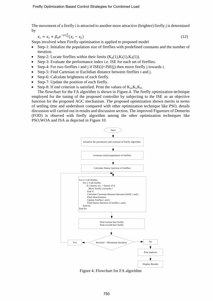
The flowchart for the FA algorithm is shown in Figure.4. The firefly optimization technique
employed for the tuning of the proposed controller by subjecting to the ISE as an objective
function for the proposed AGC mechanism. The proposed optimization shown merits in terms
of settling time and undershoot compared with other optimization technique like PSO, details
discussion will carried out in results and discussion section. The improved Figureure of Demerits
(FOD) is obseved with firefly algorithm among the other optimization techniques like
PSO,WOA and ISA as depicted in Figure 10.
Initialize the parameters and constant of firefly algorithm.
Generate initial population of fireflies
Calculate fitness function of fireflies
For i=1:all firefles
For j=1:all fireflis
If ( fitness of j < fitness of i)
Move firefly j towards i
End if
Calculate Cartesian distance between firefly i and j
Find attractiveness
Update fireflies i and j
Find fitness function of fireflies i and j
End for
End for
Find current best firefly
Find overall best firefly
Iteretion < Maximum Iteration NoYes
Post analysis
Display Results
Start
Figure 4. Flowchart for FA algorithm
Firefly Optimization Based Control Strategies for Combined Load
750

Table 1. Different optimized value of the PID Controllers.
First Controller Area Second Controller Area
-Kp -Ki -Kd -Kp -Ki -Kd
PSO based Controller
0.8642 3.9465 1.0650 6.5259 8.6860 1.6050
Proposed Based
Controller 9.4725 6.0346 5.0515 10.1236 8.3690 4.5659
4. Small Signal Stability Analysis
Table 2. Comparison of Eigenvalue for the Proposed System using
Different Tuning Techniques
Eigenvalue parameter with PSO-tuned PID
controller Eigenvalue parameter with Proposed controller
-22.9651533618715 ± 7.00901478655593i -22.9652120355601 ± 7.00904365351924i
-22.9653389360014 ± 7.00878748498818i -22.9653524912227 ± 7.00876531311043i
-16.3584086772461 -16.5866375258943
-11.9021173369546 ± 1.18657066022932i -13.5469479515264 ± 4.09399113424285i
1.46094290833100 ± 6.84703178618107i 3.17713516624120 ± 7.30570130157552i
-2.40046652848984 ± 5.82239205587684i 1.07498160037394 ± 6.57547269368190i
-2.36297989706296 ± 5.81981147410600i -2.35978637444866 ± 5.82181115438432i
0.549819201903966 ± 3.56492959407652i -2.37316925750112 + 5.80613706169438i
-3.20669847667353 -4.11915201035780
-2.15664879263664 ± 0.696914905120297i -2.07605889968972 ± 0.651130486932550i
-2.07404225607422 ± 0.599512330312577i -2.12679819645581 + 0.680856754668467i
-1.23083371146837 -1.22700518002658
-0.546652452682919 -0.721355854968881
-0.152651571359190 -0.152623686260235
-0.152664080804201 -0.152653116542236
-0.0960195651703970 -0.0960272317500690
-0.0959826631503419 -0.0960080664059280
-0.0376525850704740 -0.0397515778264082
-0.0398955360047818 -0.0388576381582553
-0.0562309322003325 -0.0530957904679813
-0.0509924285256260 -0.0510681196239602
-0.000141767199723264 -0.000141767594070001
-0.000141767648456844 -0.000141767461625939
A. K. Sahani, et al.
751

The proposed system includes diverse generating systems. Figure.3 shows the proposed
system having thermal and hydro generating system. Small signal stability is one of the important
ways to study the stability of the system. This is done using the eigenvalue analysis. Figure.3
shows the transfer function model of the proposed system. Small signal stability analysis is done
using the state space representation governed by the following equations.
(13)
(14)
0=− AI (15)
Where,
X = [X1 X2 … XN]T is the state vector and N is the number of state variables
U = [U1 U2 … UL]T is the control vector and L is the number of control variables
Y = [Y1 Y2 … YN]T is the output vector and P is the number of output variables
= eigenvalue of the proposed system
Table 2 shows the comparison of the eigenvalues of the proposed system for the PSO based
PID controller and FA based PID controller. First of all proposed system is represented in state
space form of Eq. (13) and eigenvalues from Eq. (15) are calculated. The position of eigenvalue
decides stability of the system. For the system to be stable all eigenvalues should lie on the left
side of the imaginary axis. The real eigenvalue represents non-oscillatory mode and complex
conjugate eigenvalue represent oscillatory mode.
5. Result and Discussions
Figure 5. Frequency Deviation in Area-1
The proposed control scheme of the two-area interconnected power system incorporating
LFC-AVR loop has been simulated in the MATLAB/SIMULINK environment. The proposed
model is shown in Figure 3 and the detailed model of the boiler and exciter has been depicted in
the Figure 1 and Figure 2 respectively. PID controller is used as the controller for the LFC of the
proposed system. In this research work, FA and PSO optimization techniques have been used
for the optimization of the proposed controller and their effects on the system dynamics have
been compared. Small signal stability analysis of the system has been performed for the proposed
model given in Figure 3. Eigenvalues of the proposed control scheme has been compared with
PSO based PID controller to show the effectiveness of the proposed model. Table 1 compares
the eigenvalues of both the cases which shows that the system becomes more stable when the
BUAXX +=
CXY =
0 5 10 15-2
-1.5
-1
-0.5
0
0.5
1
Time (sec.)
Fre
qu
ency
dev
iati
on
(H
z)
With Proposed Controller
With PSO based controller
Without secondary controller
Firefly Optimization Based Control Strategies for Combined Load
752
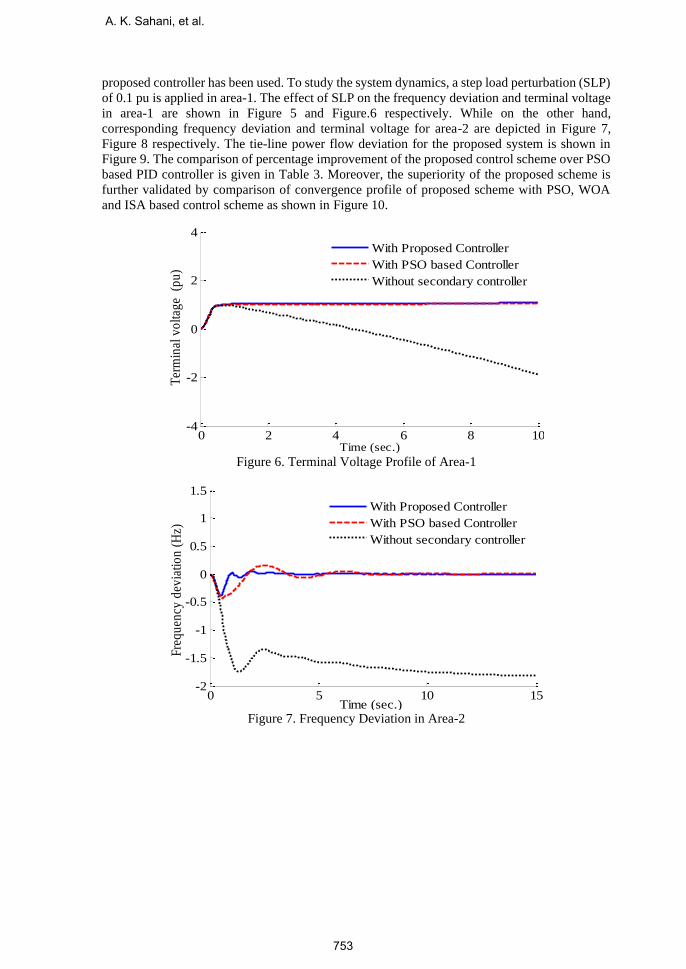
proposed controller has been used. To study the system dynamics, a step load perturbation (SLP)
of 0.1 pu is applied in area-1. The effect of SLP on the frequency deviation and terminal voltage
in area-1 are shown in Figure 5 and Figure.6 respectively. While on the other hand,
corresponding frequency deviation and terminal voltage for area-2 are depicted in Figure 7,
Figure 8 respectively. The tie-line power flow deviation for the proposed system is shown in
Figure 9. The comparison of percentage improvement of the proposed control scheme over PSO
based PID controller is given in Table 3. Moreover, the superiority of the proposed scheme is
further validated by comparison of convergence profile of proposed scheme with PSO, WOA
and ISA based control scheme as shown in Figure 10.
Figure 6. Terminal Voltage Profile of Area-1
Figure 7. Frequency Deviation in Area-2
0 2 4 6 8 10-4
-2
0
2
4
Time (sec.)
Ter
min
al v
olt
age
(p
u)
With Proposed Controller
With PSO based Controller
Without secondary controller
0 5 10 15-2
-1.5
-1
-0.5
0
0.5
1
1.5
Time (sec.)
Fre
qu
ency
dev
iati
on
(H
z)
With Proposed Controller
With PSO based Controller
Without secondary controller
A. K. Sahani, et al.
753
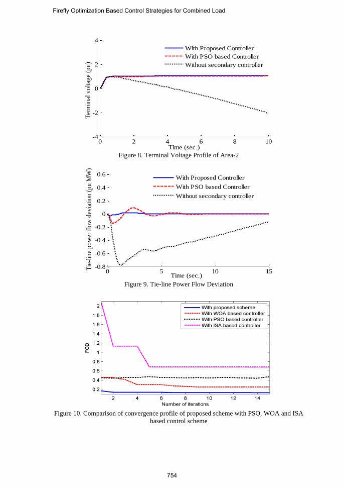
Figure 8. Terminal Voltage Profile of Area-2
Figure 9. Tie-line Power Flow Deviation
Figure 10. Comparison of convergence profile of proposed scheme with PSO, WOA and ISA
based control scheme
0 2 4 6 8 10-4
-2
0
2
4
Time (sec.)
Ter
min
al v
olt
age
(pu
)
With Proposed Controller
With PSO based Controller
Without secondary controller
0 5 10 15-0.8
-0.6
-0.4
-0.2
0
0.2
0.4
0.6
Time (sec.)
Tie
-lin
e p
ow
er f
low
dev
iati
on
(p
u M
W)
With Proposed Controller
With PSO based Controller
Without secondary controller
Firefly Optimization Based Control Strategies for Combined Load
754
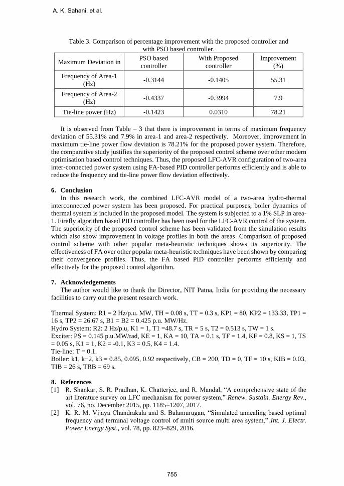
Table 3. Comparison of percentage improvement with the proposed controller and
with PSO based controller.
Maximum Deviation in PSO based
controller
With Proposed
controller
Improvement
(%)
Frequency of Area-1
(Hz) -0.3144 -0.1405 55.31
Frequency of Area-2
(Hz) -0.4337 -0.3994 7.9
Tie-line power (Hz) -0.1423 0.0310 78.21
It is observed from Table – 3 that there is improvement in terms of maximum frequency
deviation of 55.31% and 7.9% in area-1 and area-2 respectively. Moreover, improvement in
maximum tie-line power flow deviation is 78.21% for the proposed power system. Therefore,
the comparative study justifies the superiority of the proposed control scheme over other modern
optimisation based control techniques. Thus, the proposed LFC-AVR configuration of two-area
inter-connected power system using FA-based PID controller performs efficiently and is able to
reduce the frequency and tie-line power flow deviation effectively.
6. Conclusion
In this research work, the combined LFC-AVR model of a two-area hydro-thermal
interconnected power system has been proposed. For practical purposes, boiler dynamics of
thermal system is included in the proposed model. The system is subjected to a 1% SLP in area-
1. Firefly algorithm based PID controller has been used for the LFC-AVR control of the system.
The superiority of the proposed control scheme has been validated from the simulation results
which also show improvement in voltage profiles in both the areas. Comparison of proposed
control scheme with other popular meta-heuristic techniques shows its superiority. The
effectiveness of FA over other popular meta-heuristic techniques have been shown by comparing
their convergence profiles. Thus, the FA based PID controller performs efficiently and
effectively for the proposed control algorithm.
7. Acknowledgements
The author would like to thank the Director, NIT Patna, India for providing the necessary
facilities to carry out the present research work.
Thermal System: R1 = 2 Hz/p.u. MW, TH = 0.08 s, TT = 0.3 s, KP1 = 80, KP2 = 133.33, TP1 =
16 s, TP2 = 26.67 s, B1 = B2 = 0.425 p.u. MW/Hz.
Hydro System: R2: 2 Hz/p.u, K1 = 1, T1 =48.7 s, TR = 5 s, T2 = 0.513 s, TW = 1 s.
Exciter: PS = 0.145 p.u.MW/rad, KE = 1, KA = 10, TA = 0.1 s, TF = 1.4, KF = 0.8, KS = 1, TS
= 0.05 s, K1 = 1, K2 = -0.1, K3 = 0.5, K4 = 1.4.
Tie-line: T = 0.1.
Boiler: k1, k¬2, k3 = 0.85, 0.095, 0.92 respectively, CB = 200, TD = 0, TF = 10 s, KIB = 0.03,
TIB = 26 s, TRB = 69 s.
8. References
[1] R. Shankar, S. R. Pradhan, K. Chatterjee, and R. Mandal, “A comprehensive state of the
art literature survey on LFC mechanism for power system,” Renew. Sustain. Energy Rev.,
vol. 76, no. December 2015, pp. 1185–1207, 2017.
[2] K. R. M. Vijaya Chandrakala and S. Balamurugan, “Simulated annealing based optimal
frequency and terminal voltage control of multi source multi area system,” Int. J. Electr.
Power Energy Syst., vol. 78, pp. 823–829, 2016.
A. K. Sahani, et al.
755

[3] N. Qin, C. L. Bak, H. Abildgaard, and Z. Chen, “Multi-Stage Optimization Based
Automatic Voltage Control Systems Considering Wind Power Forecasting Errors,” vol.
8950, no. c, pp. 1–15, 2016.
[4] S. M. A. E. S. Ali, “Load frequency controller design of a two-area system composing of
PV grid and thermal generator via firefly algorithm,” Neural Comput. Appl., 2016.
[5] D. Guha, P. Kumar, and S. Banerjee, “Symbiotic organism search algorithm applied to load
frequency control of multi-area power system,” Energy Syst., 2017.
[6] A. Prakash, S. Murali, R. Shankar, and R. Bhushan, “HVDC tie-link modeling for
restructured AGC using a novel fractional order cascade controller,” Electr. Power Syst.
Res., vol. 170, no. September 2018, pp. 244–258, 2019.
[7] R. K. Sahu, S. Panda, and N. K. Yegireddy, “A novel hybrid DEPS optimized fuzzy PI/PID
controller for load frequency control of multi-area interconnected power systems,” J.
Process Control, vol. 24, no. 10, pp. 1596–1608, 2014.
[8] M. Farahani and S. Ganjefar, “Solving LFC problem in an interconnected power system
using superconducting magnetic energy storage,” Phys. C Supercond. its Appl., vol. 487,
no. February, pp. 60–66, 2013.
[9] S. D. Madasu, M. L. S. S. Kumar, and A. K. Singh, “Comparable investigation of
backtracking search algorithm in automatic generation control for two area reheat
interconnected thermal power system,” Appl. Soft Comput. J., vol. 55, pp. 197–210, 2017.
[10] S. Baghya Shree and N. Kamaraj, “Hybrid Neuro Fuzzy approach for automatic generation
control in restructured power system,” Int. J. Electr. Power Energy Syst., vol. 74, pp. 274–
285, 2016.
[11] K. P. S. Parmar, S. Majhi, and D. P. Kothari, “LFC of an interconnected power system with
multi-source power generation in deregulated power environment,” Int. J. Electr. Power
Energy Syst., vol. 57, pp. 277–286, 2014.
[12] R. Shankar, K. Chatterjee, and R. Bhushan, “Impact of energy storage system on load
frequency control for diverse sources of interconnected power system in deregulated power
environment,” Int. J. Electr. Power Energy Syst., vol. 79, pp. 11–26, 2016.
[13] A. Mortazavi et al., “Maiden application of an sine–cosine algorithm optimised FO cascade
controller in automatic generation control of multi-area thermal system incorporating dish-
Stirling solar and geothermal power plants,” Int. J. Electr. Power Energy Syst., vol. 20, no.
5, pp. 1–17, 2017.
[14] D. K. Sambariya and D. Paliwal, “Design of PIDA Controller Using Bat Algorithm for
AVR Power System,” vol. 4, no. 1, pp. 1–6, 2016.
[15] G. Sharma, R. C. Bansal, Ibraheem, and K. R. Niazi, “Application of softcomputing
technique for frequency control of the power system in a deregulated environment,” 2015
IEEE Int. Conf. Comput. Graph. Vis. Inf. Secur. CGVIS 2015, pp. 296–301, 2016.
[16] C. K. Shiva and V. Mukherjee, “A novel quasi-oppositional harmony search algorithm for
automatic generation control of power system,” Appl. Soft Comput. J., vol. 35, pp. 749–
765, 2015.
[17] R. Shankar, A. Kumar, U. Raj, and K. Chatterjee, “Fruit fly algorithm-based automatic
generation control of multiarea interconnected power system with FACTS and AC/DC
links in deregulated power environment,” Int. Trans. Electr. Energy Syst., no. August 2017,
p. e2690, 2018.
[18] Y. Arya and N. Kumar, “AGC of a multi-area multi-source hydrothermal power system
interconnected via AC/DC parallel links under deregulated environment,” Int. J. Electr.
Power Energy Syst., vol. 75, pp. 127–138, 2016.
[19] D. Guha, P. Kumar, and R. Subrata, “Whale optimization algorithm applied to load
frequency control of a mixed power system considering nonlinearities and PLL dynamics,”
Energy Syst., no. 0123456789, 2019.
[20] A. Mortazavi, V. Toğan, and A. Nuhoğlu, “Interactive search algorithm: A new hybrid
metaheuristic optimization algorithm,” Eng. Appl. Artif. Intell., vol. 71, no. October 2017,
pp. 275–292, 2018.
Firefly Optimization Based Control Strategies for Combined Load
756

A. K. Sahani is associated with the department of electrical engineering NIT
Patna, India in the capacity of associate professor and currently working
toward his Doctoral degree.
Utkarsh Raj received his M.Tech in Control Systems Engineering from
National Institute of Technology, Patna, India. His research interest includes
controller design and soft computing applications. Mr. Raj is currently
pursuing Ph.D degree from National Institute of Technology (NIT) Patna,
India.
Ravi Shankar received his Ph.D. from Indian Institute of Technology (Indian
School of Mines), Dhanbad, India. His research interest includes soft
computing and FACTS application in power system design. Dr. Shankar
presently working as an assistant professor in the Department of Electrical
Engineering, National Institute of Technology (NIT) Patna, India.
R. K. Mandal received his Ph.D. from NIT Patna, India. His research domain
is control application and electrical machine. Dr. Mandal presently working as
an assistant professor in the Department of Electrical Engineering, National
Institute of Technology (NIT) Patna, India.
A. K. Sahani, et al.
757