Fire Safety Services Design Standard - Macquarie … · Approved Document History 3 . ... Fire...
24
F Revision No. Date V1.0 Aug 2015 V1.1 Dec 2015 Fire Safety Services Desig DOCUMENT HISTORY No. of Pages Comment 19 For Review 19 For Circulation gn Standard
Transcript of Fire Safety Services Design Standard - Macquarie … · Approved Document History 3 . ... Fire...

Fire Safety
Revision
No.
Date
V1.0 Aug 2015
V1.1 Dec 2015
Fire Safety Services Design Standard
DOCUMENT HISTORY
No. of
Pages
Comment
19 For Review
19 For Circulation
Services Design Standard


Fire Safety Services Design
MUP Fire Safety Design Standard_V1.1
Name Position
Dennis Spicer Engineering Project Manager
David Matley Technical Services Manager
Standard Circulation Approval/
CIRCULATION APPROVAL
Approved
Engineering Project Manager
Technical Services Manager
Circulation Approval/Document History
3
Approved

Fire Safety Services Design
MUP Fire Safety Design Standard_V1.1
Table of Content
1. Design and Documentation 1
1.1. AUSTRALIAN STANDARDS & STATUTORY REQUIREMENTS
1.2. DEFINITION OF ESSENTIAL FIRE SAFETY MEASURES
1.3. INTRODUCTION 2
1.4. NEW BUILDINGS 3
1.5. EXISTING BUILDINGS 3
2. Fire Management System (FMS) 5
2.1. ACCESS PANELS, DOORS & HOPPERS TO FIRE RESISTING SHAFTS
2.2. Automatic Fail Safe Devices 5
2.2.1. MAGNETIC DOOR HOLDERS
2.2.2. FIRE TRIP TO SECURITY DOOR INTERFACES
2.3. AUTOMATIC FIRE DETECTION AND ALARM SYSTEM
2.3.1. FIRE INDICATOR PANEL (FIP)
2.3.2. DETECTORS 7 2.3.3. ASPIRATED SMOKE DETECTION SYSTEM (VESDA OR SIMILAR)
2.3.4. OCCUPANT WARNING SYSTEMS (OWS)
2.4. AUTOMATIC SPRINKLER SYSTEMS
2.4.1. GENERAL 8 2.4.2. WATER SUPPLIES 8 2.4.3. HAZARD CLASSIFICATIONS
2.5. EMERGENCY WARNING AND INTERCOMMUNICATION SYSTEM (EWIS)
2.5.1. EMERGENCY CONTROL PANEL (ECP)
2.5.2. EMERGENCY WARNING SYSTEM OPERATION
2.5.3. MANUAL CALL POINTS (MCP) AND WARDEN INTERCOMMUNICATION PHONES (WIP)
2.6. EMERGENCY EVACUATION PLANS
2.7. FIRE/EGRESS DOORS 10
2.8. FIRE HOSE REEL SYSTEMS 10
2.9. FIRE HYDRANT SYSTEMS 11
2.10. FIRE SEALS PROTECTING OPENINGS IN FIRE RESISTING COMPONENTS
2.11. FIRE SHUTTERS 12
2.12. GASEOUS FIRE SUPPRESSION SYSTEMS
2.13. LIGHTWEIGHT FIRE RATED CONSTRUCTION
2.14. MECHANICAL AIR HANDLING SYSTEM SHUTDOWN
2.15. PORTABLE FIRE EXTINGUISHERS & FIRE BLANKETS
2.16. REQUIRED POWER OPERATED EXIT DOORS
2.17. SMOKE & HEAT ALARM SYSTEMS
2.18. SMOKE DOORS 14
Standard Circulation Approval/
Table of Content
AUSTRALIAN STANDARDS & STATUTORY REQUIREMENTS 1
DEFINITION OF ESSENTIAL FIRE SAFETY MEASURES 1
5
ACCESS PANELS, DOORS & HOPPERS TO FIRE RESISTING SHAFTS 5
5 MAGNETIC DOOR HOLDERS 5 FIRE TRIP TO SECURITY DOOR INTERFACES 5
AUTOMATIC FIRE DETECTION AND ALARM SYSTEM 6 FIRE INDICATOR PANEL (FIP) 6
ASPIRATED SMOKE DETECTION SYSTEM (VESDA OR SIMILAR) 7 OCCUPANT WARNING SYSTEMS (OWS) 8
AUTOMATIC SPRINKLER SYSTEMS 8
HAZARD CLASSIFICATIONS 8
ENCY WARNING AND INTERCOMMUNICATION SYSTEM (EWIS) 9 EMERGENCY CONTROL PANEL (ECP) 9 EMERGENCY WARNING SYSTEM OPERATION 9 MANUAL CALL POINTS (MCP) AND WARDEN INTERCOMMUNICATION PHONES (WIP)
EMERGENCY EVACUATION PLANS 10
FIRE SEALS PROTECTING OPENINGS IN FIRE RESISTING COMPONENTS 11
ON SYSTEMS 12
LIGHTWEIGHT FIRE RATED CONSTRUCTION 12
MECHANICAL AIR HANDLING SYSTEM SHUTDOWN 13
PORTABLE FIRE EXTINGUISHERS & FIRE BLANKETS 13
REQUIRED POWER OPERATED EXIT DOORS 14
SMOKE & HEAT ALARM SYSTEMS 14
Circulation Approval/Document History
4
MANUAL CALL POINTS (MCP) AND WARDEN INTERCOMMUNICATION PHONES (WIP) 9

Fire Safety Services Design
MUP Fire Safety Design Standard_V1.1
2.19. WALL WETTING SPRINKLER & DRENCHER SYSTEMS
2.20. WARNING & OPERATIONAL SIGNS
2.21. MATERIALS AND EQUIPMENT SELECTION
2.21.1. MATERIALS 15
2.21.2. EQUIPMENT 15
2.22. INTERRUPTION TO ESSENTIAL FIRE SAFETY MEASURES
2.23. MAINTENANCE AND TESTING
3. Completion Documentation 17
Appendix A 18
3.2. Operation and Maintenance Manual Format
Operation and Maintenance Manual
Fire Safety Services Design Standard
WALL WETTING SPRINKLER & DRENCHER SYSTEMS 15
WARNING & OPERATIONAL SIGNS 15
MATERIALS AND EQUIPMENT SELECTION 15
INTERRUPTION TO ESSENTIAL FIRE SAFETY MEASURES 16
MAINTENANCE AND TESTING 16
and Maintenance Manual Format 18
Operation and Maintenance Manual 18
Table of Content
ii

Fire Safety Services Design Standard
MUP Fire Safety Design Standard_V1.1
1. DESIGN AND DOCUMENTATION
1.1. AUSTRALIAN STANDARDS
Design and documentation utilising these guidelin
current standards and requirements as a minimum:
� AS 1221 Fire Hose Reels
� AS 1603.1- 1997 Automatic fire detection and alarm systems
� AS 1668.1-1998 Fire and smoke control in multi compa
� AS 1670.1-2004 Fire detection, warning, control and intercom systems
� Design, installation and commissioning
� AS 1851 – 2005 maintenance of fire protection systems and equipment
� AS 1905.1-2005 Fire resistant door sets
� AS 1905.2-2005 Fire resistant roller shutters
� AS 1940 – 2004 The storage and handling of flammable and combustible liquids
� AS 2118.1 – 2006 Automatic fire sprinkler systems
� AS 2243 Safety in laboratories
� AS 2243.8 – 2006 Safety in laboratories
� AS 2293.1-2005 Emergency escape lighting and exit signs for buildings
� AS 2419.1-2005 Fire Hydrant installations.
� AS 2441 – 2005 Installation of fire hose reels
� AS 2444 - 2001 Portable fire extinguishers and
� AS 2941 – 2008 Fixed fire protection installations
� AS 3000 -2007 Electrical installations
� AS 3013 -2005 electrical installations
wiring system elements
� AS 3500 - National plumbing and drainage code
� AS 3786-1993 Smoke alarms.
� AS 4072 - 2005 Components for the protection of openings in fire
Service penetrations and control joints
� AS 4214.-2002 Gaseous Fire Ex
� AS 5007 – 2007 Powered doors for pedestrian access and egress
� AS 6905 – 2007 Smoke doors
� N.S.W Code of Practice
� BCA volumes 1&2 current edition
� National Code of Practice for the Safe Removal of Asbestos (NO
The above standards are not an exhaustive list of the relevant requirements. The consultant team is
required to incorporate all relevant
1.2. DEFINITION OF ESSENTIAL
Design and installation of essential fire safety measures shall include all subjects / ASPECTS pertaining, but
not restricted to the following:
Fire Safety Services Design Standard Design and Documentation
OCUMENTATION
STANDARDS & STATUTORY REQUIREMENTS
Design and documentation utilising these guidelines is to incorporate the requirements of the following
current standards and requirements as a minimum:
AS 1221 Fire Hose Reels
1997 Automatic fire detection and alarm systems – Heat detectors
1998 Fire and smoke control in multi compartment buildings
2004 Fire detection, warning, control and intercom systems - System
Design, installation and commissioning – Fire
2005 maintenance of fire protection systems and equipment
2005 Fire resistant door sets
2005 Fire resistant roller shutters
2004 The storage and handling of flammable and combustible liquids
2006 Automatic fire sprinkler systems - General system
AS 2243 Safety in laboratories - Planning and operational aspects
2006 Safety in laboratories – fume cupboards
2005 Emergency escape lighting and exit signs for buildings
2005 Fire Hydrant installations.
2005 Installation of fire hose reels
2001 Portable fire extinguishers and fire blankets – Selection and location.
2008 Fixed fire protection installations – Pump set systems
2007 Electrical installations
2005 electrical installations- classification of the fire and mechanical performance of
system elements
National plumbing and drainage code
1993 Smoke alarms.
2005 Components for the protection of openings in fire-resistant separating elements
Service penetrations and control joints
2002 Gaseous Fire Extinguishing systems
2007 Powered doors for pedestrian access and egress
2007 Smoke doors
N.S.W Code of Practice – Plumbing and Drainage 2006.
BCA volumes 1&2 current edition
National Code of Practice for the Safe Removal of Asbestos (NOHSC: 2002 -
The above standards are not an exhaustive list of the relevant requirements. The consultant team is
required to incorporate all relevant and current standards into project specific design and documentation.
ESSENTIAL FIRE SAFETY MEASURES
Design and installation of essential fire safety measures shall include all subjects / ASPECTS pertaining, but
not restricted to the following:
Design and Documentation
Dec 2015
1
es is to incorporate the requirements of the following
Heat detectors
System
2004 The storage and handling of flammable and combustible liquids
Selection and location.
classification of the fire and mechanical performance of
resistant separating elements -
- 1988)
The above standards are not an exhaustive list of the relevant requirements. The consultant team is
standards into project specific design and documentation.
Design and installation of essential fire safety measures shall include all subjects / ASPECTS pertaining, but

Fire Safety Services Design Sta
MUP Fire Safety Design Standard_V1.1
� Fire Management System (FMS)
� Access panels, doors & hoppers to fire resisting shafts
� Automatic fail safe devices
� Automatic fire detection and alarm systems
� Automatic fire sprinkler systems
� Emergency lifts (refer to electrical services section)
� Emergency lighting (refer to electrical services section)
� Emergency warning and
� Emergency evacuation plans
� Exit signs (refer to electrical services section)
� Fire dampers (refer to mechanical services section)
� Fire doors
� Fire hose reel systems
� Fire hydrant systems
� Fire seals protecting openin
� Fire shutters
� Gaseous fire suppression systems
� Lightweight fire rated construction
� Mechanical air handling system shutdown
� Portable fire extinguishers & fire
� Pressurising systems (refer to mechanical services section)
� Required power operated exit doors
� Smoke and heat vents (refer to mechanical services section)
� Smoke and heat alarm systems
� Smoke dampers (refer to mechanical services section)
� Smoke doors
� Standby power systems (refer to electrical services section)
� Wall wetting sprinkler and drencher systems
� Warning and operational signs
� Alternate fire solutions
� Service penetrations (refer to architectural)
1.3. INTRODUCTION
Most University buildings are considered to be classified as Class 9b buildings, i.e., 'an assembly building,
including a trade workshop, laboratory, or the like in a primary school or secondary school', as defined by
the Building Code of Australia (BCA). This Class 9b classifi
computer rooms, laboratories, workshops, office areas and the like, but does not apply to other specialised
buildings such as student accommodation (and other premises containing areas for sleeping occupants
carparks, farm buildings and the like.
Additionally, some buildings may contain areas which are required to be designed to suit Entertainment
requirements.
Fire Safety Services Design Standard Design and
Fire Management System (FMS)
Access panels, doors & hoppers to fire resisting shafts
l safe devices
Automatic fire detection and alarm systems
Automatic fire sprinkler systems
Emergency lifts (refer to electrical services section) – Location to be advised
Emergency lighting (refer to electrical services section)
Emergency warning and intercommunication systems (EWIS)
Emergency evacuation plans
Exit signs (refer to electrical services section)
Fire dampers (refer to mechanical services section) – Location to be advised
Fire hose reel systems
protecting openings in fire resisting components
Gaseous fire suppression systems
Lightweight fire rated construction (refer to architectural) – Location to be advised
Mechanical air handling system shutdown
Portable fire extinguishers & fire blankets
Pressurising systems (refer to mechanical services section)
uired power operated exit doors
Smoke and heat vents (refer to mechanical services section)
Smoke and heat alarm systems
Smoke dampers (refer to mechanical services section)
Standby power systems (refer to electrical services section)
Wall wetting sprinkler and drencher systems
Warning and operational signs
Alternate fire solutions buildings
Service penetrations (refer to architectural)
ngs are considered to be classified as Class 9b buildings, i.e., 'an assembly building,
including a trade workshop, laboratory, or the like in a primary school or secondary school', as defined by
the Building Code of Australia (BCA). This Class 9b classification generally applies to all teaching spaces,
computer rooms, laboratories, workshops, office areas and the like, but does not apply to other specialised
buildings such as student accommodation (and other premises containing areas for sleeping occupants
carparks, farm buildings and the like.
Additionally, some buildings may contain areas which are required to be designed to suit Entertainment
Design and Documentation
2
Location to be advised
Location to be advised
Location to be advised
ngs are considered to be classified as Class 9b buildings, i.e., 'an assembly building,
including a trade workshop, laboratory, or the like in a primary school or secondary school', as defined by
cation generally applies to all teaching spaces,
computer rooms, laboratories, workshops, office areas and the like, but does not apply to other specialised
buildings such as student accommodation (and other premises containing areas for sleeping occupants),
Additionally, some buildings may contain areas which are required to be designed to suit Entertainment

Fire Safety Services Design Standard
MUP Fire Safety Design Standard_V1.1
As the essential fire safety measures proposed to be installed within a building are determined b
classification of the building, details regarding the building classification, together with any special
Entertainment requirements, shall be submitted by the Consultant Team during initial design development,
for approval by Macquarie University Pro
Many University buildings contain health and fire hazards far in excess of those normally found in typical
Class 9b assembly buildings. Moreover the University's commitment to
many cases a higher degree of life safety provision than that provided by the building regulat
Alternate Fire Solution buildings or buildings used for revenue.
The University's minimum requirements for fire protection systems are stated below.
These requirements may be in addition to, but not in substitution of legislative requirements.
1.4. NEW BUILDINGS
As a minimum, the essential fire safety measures provided in University buildings shall be designed and
installed in accordance with the minimum legislative requirement
Regulations, Australian Standards, Local Council, NSW Fire Brigades,
requirements.
Each building shall be provided with the appropriate fire suppression, detection,
egress provisions, all designed and installed in accordance with the requirements of the
Provisions” of the BCA.
Additional measures may also be required, as stated in these guidelines, to meet specific building haz
and/or University Insurers requirements.
Where it is proposed that the
“Alternative Solution” in lieu of complying with the
Consultant Team shall consult and seek approval for all proposed non
MQP, during initial design development and any relevant authorities.
The Consultant Team is also required to consult with
Group and User Groups, to discuss any additional essential fire safety measures which may be required to
be included in the design, in order to suit the proposed occupancy, associated hazards and the overall fire
exposure risk.
The additional measures shall be determined
relating to the fire safety of the building, including consequence of loss and likelihood of loss.
1.5. EXISTING BUILDINGS
The policy for the refurbishment of existing essentia
generally be as for new buildings. However, as current building regulations are generally aimed at new
buildings being constructed today, there are few existing buildings in the University that have be
constructed under current regulations.
Whilst every endeavour is made to comply with regulations during refurbishments and upgrades, it is
unlikely that the full extent of the building regulations can always be met.
Therefore in many cases involving exi
complying with the “Deemed
For all existing essential fire safety measures within a building proposed for refurbishment, the
Standard of Performance shall be reviewed by the Consultant Team for compliance with the current BCA
and current Australian Standard requirements.
The details of this review and the proposed upgrade strategy for the existing essential fire safety
within the refurbishment area shall be submitted to
and comment.
These details will assist in the determination of the extent of modification and upgrade of existing essential
fire safety measures required to be incorporated into the refurbishment works.
Fire Safety Services Design Standard Design and
As the essential fire safety measures proposed to be installed within a building are determined b
classification of the building, details regarding the building classification, together with any special
Entertainment requirements, shall be submitted by the Consultant Team during initial design development,
Macquarie University Property Department (MQP).
Many University buildings contain health and fire hazards far in excess of those normally found in typical
Class 9b assembly buildings. Moreover the University's commitment to Work Health & Safety requires in
ree of life safety provision than that provided by the building regulat
Alternate Fire Solution buildings or buildings used for revenue.
The University's minimum requirements for fire protection systems are stated below.
y be in addition to, but not in substitution of legislative requirements.
As a minimum, the essential fire safety measures provided in University buildings shall be designed and
installed in accordance with the minimum legislative requirements incorporating all
Regulations, Australian Standards, Local Council, NSW Fire Brigades, Work Health
Each building shall be provided with the appropriate fire suppression, detection,
egress provisions, all designed and installed in accordance with the requirements of the
Additional measures may also be required, as stated in these guidelines, to meet specific building haz
and/or University Insurers requirements.
Where it is proposed that the “Performance Requirements” of the BCA will be adopted to develop an
in lieu of complying with the “Deemed-to-Satisfy (DtS) Provisions”
tant Team shall consult and seek approval for all proposed non-complying BCA DtS provisions with
, during initial design development and any relevant authorities.
The Consultant Team is also required to consult with MQP, University Risk Management, Univ
Group and User Groups, to discuss any additional essential fire safety measures which may be required to
be included in the design, in order to suit the proposed occupancy, associated hazards and the overall fire
asures shall be determined in consultation with MQP incorporating details and issues
relating to the fire safety of the building, including consequence of loss and likelihood of loss.
The policy for the refurbishment of existing essential fire safety measures within existing buildings shall
generally be as for new buildings. However, as current building regulations are generally aimed at new
buildings being constructed today, there are few existing buildings in the University that have be
constructed under current regulations.
Whilst every endeavour is made to comply with regulations during refurbishments and upgrades, it is
unlikely that the full extent of the building regulations can always be met.
Therefore in many cases involving existing building refurbishment, “Alternative Solutions”
“Deemed-to-Satisfy (DtS) Provisions” of the BCA may need to be developed.
For all existing essential fire safety measures within a building proposed for refurbishment, the
Standard of Performance shall be reviewed by the Consultant Team for compliance with the current BCA
and current Australian Standard requirements.
The details of this review and the proposed upgrade strategy for the existing essential fire safety
within the refurbishment area shall be submitted to MQP during the initial design development for review
These details will assist in the determination of the extent of modification and upgrade of existing essential
es required to be incorporated into the refurbishment works.
Design and Documentation
3
As the essential fire safety measures proposed to be installed within a building are determined by the
classification of the building, details regarding the building classification, together with any special
Entertainment requirements, shall be submitted by the Consultant Team during initial design development,
Many University buildings contain health and fire hazards far in excess of those normally found in typical
Work Health & Safety requires in
ree of life safety provision than that provided by the building regulations, example,
The University's minimum requirements for fire protection systems are stated below.
y be in addition to, but not in substitution of legislative requirements.
As a minimum, the essential fire safety measures provided in University buildings shall be designed and
s incorporating all current Statutory
Work Health Safety and WorkCover
Each building shall be provided with the appropriate fire suppression, detection, emergency warning and
egress provisions, all designed and installed in accordance with the requirements of the “Deemed-to-Satisfy
Additional measures may also be required, as stated in these guidelines, to meet specific building hazards
of the BCA will be adopted to develop an
Satisfy (DtS) Provisions” of the BCA, the
complying BCA DtS provisions with
, University Risk Management, University WHS
Group and User Groups, to discuss any additional essential fire safety measures which may be required to
be included in the design, in order to suit the proposed occupancy, associated hazards and the overall fire
incorporating details and issues
relating to the fire safety of the building, including consequence of loss and likelihood of loss.
l fire safety measures within existing buildings shall
generally be as for new buildings. However, as current building regulations are generally aimed at new
buildings being constructed today, there are few existing buildings in the University that have been
Whilst every endeavour is made to comply with regulations during refurbishments and upgrades, it is
“Alternative Solutions” in lieu of
of the BCA may need to be developed.
For all existing essential fire safety measures within a building proposed for refurbishment, the existing
Standard of Performance shall be reviewed by the Consultant Team for compliance with the current BCA
The details of this review and the proposed upgrade strategy for the existing essential fire safety measures
during the initial design development for review
These details will assist in the determination of the extent of modification and upgrade of existing essential

Fire Safety Services Design Standard
MUP Fire Safety Design Standard_V1.1
Fire Safety Services Design Standard De
Design and Documentation
4

Fire Safety Services Design Standard
MUP Fire Safety Design Standard_V1.1
2. FIRE MANAGEMENT SYST
All existing building fire indicator panels (FIP's), fire sprinkler systems, sprinkler control valves and fire
pumps installed throughout all University Buildings ar
Simplex Fire Alarm network
New fire equipment, must be connected to the FMS to provide adequate details required to monitor the
equipment and any faults/alarms
to indicate any fire alarms.
The Consultant Team shall fully consult with
project, to determine the extent off modification required
incorporating new FIP's, sprinkler systems and fire pumps into the project works.
Due to the complex nature of the FMS, it is required that an approved University contractor performs all
project related alteration wor
FMS, including any required programming and modification to existing FMS equipment. These works shall
be allowed to be provided as part of the overall project works and include
equipment:
� Main Campus FMS FIP
� Subsequent Fire Indicator Panels
2.1. ACCESS PANELS, DOORS
All fire rated access panels, doors & hoppers shall be:
a. Equal to the FRL of the shaft in which they a
b. Provided with identification labelling in accordance with the requirements of AS4072.1 Appendix B
and AS1851-2005
c. Detailed on the building essential fire safety measure asset register and as built drawings.
2.2. AUTOMATIC FAIL SAFE DEVICES
Automatic fail safe devices include magnetic door holders and fire trips to security door interfaces (electric
strikes, electric mortise locks, drop bolts, magnetic locks
condition is sensed via the building fire sprinkler or fire detection system. These devices shall be normally
energised to enable the devices to return to the fail safe position when power to the device is lost in
accordance with the requirements of AS1851
2.2.1. MAGNETIC DOOR HOLDERS
The consultant team shall fully liaise with MQP and the Project User Group to determine requirements and
locations of fire and/or smoke rated doors required to be normally held open by low voltage magnetic door
holders. Magnetic door holders shall be mounted at the top of fire doors
PVC bases are not permitted. Each magnet shall be fitted with a local release button and where more than
one door panel is fitted to a single opening, then one switch shall re
parts of the magnet shall be secured rigidly.
Fire & Smoke doors not locked by the security system shall have the magnetic door holders installed on a
separate control loops to security door interfaces and air conditio
isolation facilities for each loop located at the FIP.
2.2.2. FIRE TRIP TO SECURITY DOOR INTERFACES
The consultant team shall fully liaise with MQP, Security Services and the Project User Group to determine
the locations of security door interfaces installed on required egress doors which are proposed to be
normally locked by the electronic security system and are required to automatically unlock in the event of
fire alarm activation.
Fire Safety Services Design Standard Fire Management
FIRE MANAGEMENT SYSTEM (FMS)
All existing building fire indicator panels (FIP's), fire sprinkler systems, sprinkler control valves and fire
pumps installed throughout all University Buildings are connected to the main campus FMS FIP via the
network located in Security building C1A.
New fire equipment, must be connected to the FMS to provide adequate details required to monitor the
equipment and any faults/alarms and each building FIP shall be interfaced with the Security system (Cardex)
The Consultant Team shall fully consult with MQP during the initial design development stage for each
project, to determine the extent off modification required to the FMS when modifying existing or
incorporating new FIP's, sprinkler systems and fire pumps into the project works.
Due to the complex nature of the FMS, it is required that an approved University contractor performs all
project related alteration works associated with the installation and connection of devices connected to the
FMS, including any required programming and modification to existing FMS equipment. These works shall
be allowed to be provided as part of the overall project works and include all modifications to the following
Main Campus FMS FIP
Subsequent Fire Indicator Panels
DOORS & HOPPERS TO FIRE RESISTING SHAFTS
All fire rated access panels, doors & hoppers shall be:
Equal to the FRL of the shaft in which they are installed in (refer to architectural)
Provided with identification labelling in accordance with the requirements of AS4072.1 Appendix B
Detailed on the building essential fire safety measure asset register and as built drawings.
EVICES
Automatic fail safe devices include magnetic door holders and fire trips to security door interfaces (electric
cks, drop bolts, magnetic locks etc.) are required to activate when a fire/smoke
n is sensed via the building fire sprinkler or fire detection system. These devices shall be normally
energised to enable the devices to return to the fail safe position when power to the device is lost in
accordance with the requirements of AS1851-2005.
AGNETIC DOOR HOLDERS
The consultant team shall fully liaise with MQP and the Project User Group to determine requirements and
locations of fire and/or smoke rated doors required to be normally held open by low voltage magnetic door
olders shall be mounted at the top of fire doors with a wall mounted metal base
not permitted. Each magnet shall be fitted with a local release button and where more than
one door panel is fitted to a single opening, then one switch shall release all magnetic door holders. Both
parts of the magnet shall be secured rigidly.
Fire & Smoke doors not locked by the security system shall have the magnetic door holders installed on a
to security door interfaces and air conditioning fire trip cabling with individual
isolation facilities for each loop located at the FIP.
FIRE TRIP TO SECURITY DOOR INTERFACES
The consultant team shall fully liaise with MQP, Security Services and the Project User Group to determine
security door interfaces installed on required egress doors which are proposed to be
normally locked by the electronic security system and are required to automatically unlock in the event of
Fire Management System (FMS)
5
All existing building fire indicator panels (FIP's), fire sprinkler systems, sprinkler control valves and fire
e connected to the main campus FMS FIP via the
New fire equipment, must be connected to the FMS to provide adequate details required to monitor the
building FIP shall be interfaced with the Security system (Cardex)
during the initial design development stage for each
to the FMS when modifying existing or
Due to the complex nature of the FMS, it is required that an approved University contractor performs all
ks associated with the installation and connection of devices connected to the
FMS, including any required programming and modification to existing FMS equipment. These works shall
all modifications to the following
SHAFTS
(refer to architectural)
Provided with identification labelling in accordance with the requirements of AS4072.1 Appendix B
Detailed on the building essential fire safety measure asset register and as built drawings.
Automatic fail safe devices include magnetic door holders and fire trips to security door interfaces (electric
are required to activate when a fire/smoke
n is sensed via the building fire sprinkler or fire detection system. These devices shall be normally
energised to enable the devices to return to the fail safe position when power to the device is lost in
The consultant team shall fully liaise with MQP and the Project User Group to determine requirements and
locations of fire and/or smoke rated doors required to be normally held open by low voltage magnetic door
with a wall mounted metal base,
not permitted. Each magnet shall be fitted with a local release button and where more than
lease all magnetic door holders. Both
Fire & Smoke doors not locked by the security system shall have the magnetic door holders installed on a
ning fire trip cabling with individual
The consultant team shall fully liaise with MQP, Security Services and the Project User Group to determine
security door interfaces installed on required egress doors which are proposed to be
normally locked by the electronic security system and are required to automatically unlock in the event of

Fire Safety Services Design Standar
MUP Fire Safety Design Standard_V1.1
To ensure that security door interfaces
from the FIP and connect directly to the door interface and not via any electr
Fire trips to security door interfaces shall be installed on a separ
and air conditioning fire trip cabling
MQP shall advise if any smoke doors are to be controlled by the security system and closed on fire trip.
All doors provided with a fire trip to a security door interface shall also be provided with a green Break Glass
Unit labelled “door release” and fixed to the wall adjacent to the door handle. This UNIVERSITY requirement
is to ensure egress through the do
A4 signage shall also be mounted on the door at eye level. The signage shall be green and carry white
lettering indicating:
"EMERGENCY EXIT ONLY”
Include “DOOR ALARMED" if applicable.
All egress doors provided with security screamers shall be arranged so that the security screamer device is
deactivated on a fire trip signal.
The details of all fire trips to security interfaces devices shall be included on the building essential fire safety
measure asset register and the associated drawings
2.3. AUTOMATIC FIRE DETECTION
The University currently has a variety of existing fire detection and alarm systems and FIP's installed
throughout its buildings, including older type single wire series
traditional conventional and addressable fire systems.
Unless instructed otherwise the fire system is to be upgraded to an addressable system, the existing FIP
shall be upgraded to Simplex 4100
addressable and the non-affected area to be conventional detectors.
Each addressable loop circuit shall not exceed 80% of the design capacity recommended by the
manufacturer.
When upgrading or extending p
out by an alternate contractor to the current essential services maintenance contractor,
essential services maintenance contractor
satisfied that the new work is fully operational to sign off and satisfies the system requirements. The cost of
this inspection is to be included in the installation tender sum for the Project.
On Practical Completion the design team
to be satisfied that the new work is fully operational and satisfies the system requirements.
2.3.1. FIRE INDICATOR PANEL (FIP)
a. New FIP’s shall be fully addressable
b. New FIP's proposed to be installed as part of a building refurbishment or within a new building shall be
analogue addressable type. FIP's shall be sized to adequately serve the entire building in which
located with a minimum of 20% spare capacity on all control loops/lines
c. FIP's shall be located at the building entrance designated as the entrance most accessible to the NSW
Fire Brigade, ie, the entrance accessible to a fire appliance
d. The FIP shall be placed in
building occupants. Under no circumstances are FIP's to be located in storerooms or offices or other
"out of the way" places
e. Separate isolating facilities for each group of equipmen
occupant warning system, magnetic door holders, security interface devices, air conditioning trips,
sprinkler system interfaces and main fire bell/strobe
f. Manual call points (MCP) shall be connected direct
of the one red MCP required to be provided at the FIP
g. Fire sprinkler & hydrant system valve monitor switches (one indicator per location) open, closed
Fire Safety Services Design Standard Fire Management
To ensure that security door interfaces are able to be classified as fail safe devices, fire trip cabling shall run
from the FIP and connect directly to the door interface and not via any electronic security system controller
Fire trips to security door interfaces shall be installed on a separate control loop to magnetic door holders
trip cabling with individual isolation facilities for each loop located at the FIP.
MQP shall advise if any smoke doors are to be controlled by the security system and closed on fire trip.
All doors provided with a fire trip to a security door interface shall also be provided with a green Break Glass
and fixed to the wall adjacent to the door handle. This UNIVERSITY requirement
is to ensure egress through the door is available in the event of all types of emergencies.
A4 signage shall also be mounted on the door at eye level. The signage shall be green and carry white
if applicable.
rs provided with security screamers shall be arranged so that the security screamer device is
deactivated on a fire trip signal.
The details of all fire trips to security interfaces devices shall be included on the building essential fire safety
set register and the associated drawings
DETECTION AND ALARM SYSTEM
The University currently has a variety of existing fire detection and alarm systems and FIP's installed
throughout its buildings, including older type single wire series circuit systems (Reichel type) and more
traditional conventional and addressable fire systems.
Unless instructed otherwise the fire system is to be upgraded to an addressable system, the existing FIP
shall be upgraded to Simplex 4100-SU and the new FIP shall be fully partitioned to allow the new area to be
affected area to be conventional detectors.
Each addressable loop circuit shall not exceed 80% of the design capacity recommended by the
When upgrading or extending part of an existing fire alarm system, should the installation work be carried
out by an alternate contractor to the current essential services maintenance contractor,
essential services maintenance contractor shall inspect the new work at Pract
satisfied that the new work is fully operational to sign off and satisfies the system requirements. The cost of
this inspection is to be included in the installation tender sum for the Project.
On Practical Completion the design team/consultant shall inspect the work and commissioning test sheets
to be satisfied that the new work is fully operational and satisfies the system requirements.
FIRE INDICATOR PANEL (FIP)
New FIP’s shall be fully addressable Simplex 4100-SU (or current model)
New FIP's proposed to be installed as part of a building refurbishment or within a new building shall be
analogue addressable type. FIP's shall be sized to adequately serve the entire building in which
with a minimum of 20% spare capacity on all control loops/lines
FIP's shall be located at the building entrance designated as the entrance most accessible to the NSW
Fire Brigade, ie, the entrance accessible to a fire appliance
The FIP shall be placed in a position that allows for both audible and visual fault monitoring by the
building occupants. Under no circumstances are FIP's to be located in storerooms or offices or other
Separate isolating facilities for each group of equipment interfaces shall be provided at the FIP for EWIS,
occupant warning system, magnetic door holders, security interface devices, air conditioning trips,
sprinkler system interfaces and main fire bell/strobe
Manual call points (MCP) shall be connected directly to the EWIS and not to the FIP, with the exception
of the one red MCP required to be provided at the FIP
Fire sprinkler & hydrant system valve monitor switches (one indicator per location) open, closed
Fire Management System (FMS)
6
are able to be classified as fail safe devices, fire trip cabling shall run
onic security system controller.
ate control loop to magnetic door holders
with individual isolation facilities for each loop located at the FIP.
MQP shall advise if any smoke doors are to be controlled by the security system and closed on fire trip.
All doors provided with a fire trip to a security door interface shall also be provided with a green Break Glass
and fixed to the wall adjacent to the door handle. This UNIVERSITY requirement
or is available in the event of all types of emergencies.
A4 signage shall also be mounted on the door at eye level. The signage shall be green and carry white
rs provided with security screamers shall be arranged so that the security screamer device is
The details of all fire trips to security interfaces devices shall be included on the building essential fire safety
The University currently has a variety of existing fire detection and alarm systems and FIP's installed
circuit systems (Reichel type) and more
Unless instructed otherwise the fire system is to be upgraded to an addressable system, the existing FIP
ll be fully partitioned to allow the new area to be
Each addressable loop circuit shall not exceed 80% of the design capacity recommended by the
art of an existing fire alarm system, should the installation work be carried
out by an alternate contractor to the current essential services maintenance contractor, the current
shall inspect the new work at Practical Completion and be
satisfied that the new work is fully operational to sign off and satisfies the system requirements. The cost of
/consultant shall inspect the work and commissioning test sheets
to be satisfied that the new work is fully operational and satisfies the system requirements.
New FIP's proposed to be installed as part of a building refurbishment or within a new building shall be
analogue addressable type. FIP's shall be sized to adequately serve the entire building in which it is
FIP's shall be located at the building entrance designated as the entrance most accessible to the NSW
a position that allows for both audible and visual fault monitoring by the
building occupants. Under no circumstances are FIP's to be located in storerooms or offices or other
t interfaces shall be provided at the FIP for EWIS,
occupant warning system, magnetic door holders, security interface devices, air conditioning trips,
ly to the EWIS and not to the FIP, with the exception
Fire sprinkler & hydrant system valve monitor switches (one indicator per location) open, closed

Fire Safety Services Design Standard
MUP Fire Safety Design Standard_V1.1
h. Fire sprinkler pre-action systems
i. VESDA status indication -
Where existing FIP's require modification of existing programmes and/or software to
due to refurbishment works, these modification wo
a. Carried out by an approved University contractor. The cost of these works is to be fully included in the
tender sum for the Project.
b. An suitably sized framed and covered block plan shall be installed adjacent to the FIP, showing the
extent of alarm zones and addressable detector numbering for each level and area of the building
controlled by the FIP. Each zone shall be coloured for easy identification and a CAD dwg supplied MQP.
c. Where existing fire detection and alarm systems are refurbished, a
altered to suit the works performed as part of the refurbishment. A system interface diagram/matrix
shall also be included as part of the block plan information, in accordance with the requirements of
AS1851.
d. A drill switch shall be installed on all FIP`s, and on activation shall not call the NSWFB or shut down A/C
units, but activate the EWIS/OWS and unlock all fire/smoke & Security doors.
2.3.2. DETECTORS
a. All new fire detection and alarm systems are to be provided with fully addr
with adjustable sensitivity. Detectors proposed to be connected to existing systems shall be chosen to
be fully compatible with the FIP to which they are proposed to be connected to and shall also be used in
accordance with the existing FIP equipment listing limitations
b. Detectors shall be suitably selected for each location in accordance with AS1670
c. AS1670 Appendix A - Guidance for the Selection of Detectors. Where smoke detectors are indicated as
the suggested detection device,
d. Where detectors are located in concealed spaces such as ceiling spaces, cupboards, sole occupancy
units, air handling systems and the like, remote indicators shall be provided
e. Remote indicators are required to be provided for both conventional and fully addressable type
detectors
f. All detectors shall be fully accessible for maintenance. Accessibility to concealed spaces shall be
achieved via ceiling access panels or accessible walkways. Where accessi
the use of VESDA shall be considered
g. Photoelectric smoke detectors shall be provided in all electrical distribution board, cupboards,
telecommunications cupboards, electrical switch rooms and lift motor rooms
h. For sleeping areas, sole occupancy units and paths of travel to exits, photoelectric smoke detectors are
recommended to be installed. Where it is deemed inappropriate to install these detectors due to the
possibility of unwanted alarms, combined CO & heat multisensory
i. Heat detectors connected to the FIP shall be provided within all fume cupboard exhaust flues, as
required by AS2243.8. Remote indicators shall be provided in these cases.
j. Care shall be taken to ensure that heaters, air condition
not located within the minimum required distance from heat and smoke detectors.
2.3.3. ASPIRATED SMOKE DETECTION SYSTEM (VESDA OR SIMILAR)
a. The use of VESDA shall be considered for high risk/high insurance areas.
aspirating smoke detectors shall be used in areas of sensitivity e.g. heritage, archival, valuable assets or
the like, after consultation with
b. VESDA systems shall operate independently of other detection/suppr
be connected to the building FIP and to the FMS to provide indication of all alarm levels and to allow
early response by Security Patrol
c. All VESDA alert and action alarms must not call the brigade. The Fire 1 or the Fire
configured to call the fire brigade
d. Vision Systems, the manufacturer of VESDA, shall be consulted as to the optimum design for the
particular installation. Only VESDA accredited installers shall install a VESDA system
e. If the VESDA controller is to be located remote of the area being protected a mimic panel providing
aural and visual indication of alert, action, Fire 1 and Fire 2 alarm and system faults is to be located in
the protected area.
Fire Safety Services Design Standard Fire Management
action systems - low air pressure alarm
- airflow fault, alert alarm, action alarm, fire 1 alarm, fire 2 alarm
Where existing FIP's require modification of existing programmes and/or software to
due to refurbishment works, these modification works shall be
Carried out by an approved University contractor. The cost of these works is to be fully included in the
tender sum for the Project.
framed and covered block plan shall be installed adjacent to the FIP, showing the
alarm zones and addressable detector numbering for each level and area of the building
Each zone shall be coloured for easy identification and a CAD dwg supplied MQP.
Where existing fire detection and alarm systems are refurbished, any existing block plans shall be
altered to suit the works performed as part of the refurbishment. A system interface diagram/matrix
shall also be included as part of the block plan information, in accordance with the requirements of
shall be installed on all FIP`s, and on activation shall not call the NSWFB or shut down A/C
units, but activate the EWIS/OWS and unlock all fire/smoke & Security doors.
All new fire detection and alarm systems are to be provided with fully addressable detectors, complete
with adjustable sensitivity. Detectors proposed to be connected to existing systems shall be chosen to
be fully compatible with the FIP to which they are proposed to be connected to and shall also be used in
existing FIP equipment listing limitations
Detectors shall be suitably selected for each location in accordance with AS1670
Guidance for the Selection of Detectors. Where smoke detectors are indicated as
the suggested detection device, photoelectric smoke detectors shall generally be installed
Where detectors are located in concealed spaces such as ceiling spaces, cupboards, sole occupancy
units, air handling systems and the like, remote indicators shall be provided
required to be provided for both conventional and fully addressable type
All detectors shall be fully accessible for maintenance. Accessibility to concealed spaces shall be
achieved via ceiling access panels or accessible walkways. Where accessibility to detectors is difficult,
the use of VESDA shall be considered
Photoelectric smoke detectors shall be provided in all electrical distribution board, cupboards,
telecommunications cupboards, electrical switch rooms and lift motor rooms
areas, sole occupancy units and paths of travel to exits, photoelectric smoke detectors are
recommended to be installed. Where it is deemed inappropriate to install these detectors due to the
possibility of unwanted alarms, combined CO & heat multisensory detectors may be considered
Heat detectors connected to the FIP shall be provided within all fume cupboard exhaust flues, as
required by AS2243.8. Remote indicators shall be provided in these cases.
Care shall be taken to ensure that heaters, air conditioning registers, ceiling fans and light fittings are
not located within the minimum required distance from heat and smoke detectors.
ASPIRATED SMOKE DETECTION SYSTEM (VESDA OR SIMILAR)
The use of VESDA shall be considered for high risk/high insurance areas. VESDA or comparable
aspirating smoke detectors shall be used in areas of sensitivity e.g. heritage, archival, valuable assets or
the like, after consultation with MQP as to the suitability
VESDA systems shall operate independently of other detection/suppression systems, however they shall
be connected to the building FIP and to the FMS to provide indication of all alarm levels and to allow
early response by Security Patrol
All VESDA alert and action alarms must not call the brigade. The Fire 1 or the Fire
configured to call the fire brigade
Vision Systems, the manufacturer of VESDA, shall be consulted as to the optimum design for the
particular installation. Only VESDA accredited installers shall install a VESDA system
roller is to be located remote of the area being protected a mimic panel providing
aural and visual indication of alert, action, Fire 1 and Fire 2 alarm and system faults is to be located in
Fire Management System (FMS)
7
airflow fault, alert alarm, action alarm, fire 1 alarm, fire 2 alarm
Where existing FIP's require modification of existing programmes and/or software to incorporate changes
Carried out by an approved University contractor. The cost of these works is to be fully included in the
framed and covered block plan shall be installed adjacent to the FIP, showing the
alarm zones and addressable detector numbering for each level and area of the building
Each zone shall be coloured for easy identification and a CAD dwg supplied MQP.
ny existing block plans shall be
altered to suit the works performed as part of the refurbishment. A system interface diagram/matrix
shall also be included as part of the block plan information, in accordance with the requirements of
shall be installed on all FIP`s, and on activation shall not call the NSWFB or shut down A/C
essable detectors, complete
with adjustable sensitivity. Detectors proposed to be connected to existing systems shall be chosen to
be fully compatible with the FIP to which they are proposed to be connected to and shall also be used in
Detectors shall be suitably selected for each location in accordance with AS1670
Guidance for the Selection of Detectors. Where smoke detectors are indicated as
photoelectric smoke detectors shall generally be installed
Where detectors are located in concealed spaces such as ceiling spaces, cupboards, sole occupancy
required to be provided for both conventional and fully addressable type
All detectors shall be fully accessible for maintenance. Accessibility to concealed spaces shall be
bility to detectors is difficult,
Photoelectric smoke detectors shall be provided in all electrical distribution board, cupboards,
areas, sole occupancy units and paths of travel to exits, photoelectric smoke detectors are
recommended to be installed. Where it is deemed inappropriate to install these detectors due to the
detectors may be considered
Heat detectors connected to the FIP shall be provided within all fume cupboard exhaust flues, as
ing registers, ceiling fans and light fittings are
not located within the minimum required distance from heat and smoke detectors.
VESDA or comparable
aspirating smoke detectors shall be used in areas of sensitivity e.g. heritage, archival, valuable assets or
ession systems, however they shall
be connected to the building FIP and to the FMS to provide indication of all alarm levels and to allow
All VESDA alert and action alarms must not call the brigade. The Fire 1 or the Fire 2 alarm shall not be
Vision Systems, the manufacturer of VESDA, shall be consulted as to the optimum design for the
particular installation. Only VESDA accredited installers shall install a VESDA system
roller is to be located remote of the area being protected a mimic panel providing
aural and visual indication of alert, action, Fire 1 and Fire 2 alarm and system faults is to be located in

Fire Safety Services Design
MUP Fire Safety Design Standard_V1.1
2.3.4. OCCUPANT WARNING SYSTEMS (OWS)
a. Where buildings are not provided with EWIS, an OWS shall form part of the fire detection and alarm
system
b. New OWS shall consist of an amplified sound system producing the evacuation signal in accordance
with the requirements of ISO 8201. New sounder or bell type OWS sh
University approval.
c. Sound pressure levels shall be provided in accordance with the requirements of AS1670.1.
d. New systems shall be provided with a microphone and appro
functions
e. Occupant warning speakers shall be provided in accordance with the requirements for EWIS
f. When new OWS are installed, the amplifier capacity shall be selected to provide sufficient sound levels
throughout the entire building
g. Existing OWS, such as internal fire
refurbishment, shall be modified within the refurbishment area to achieve the evacuation signal tone
and sound pressure level requirements of AS1670.1
h. Commissioning details indicating measur
drawings and within the O&M manual, for all new and refurbishment works.
2.4. AUTOMATIC SPRINKLER
2.4.1. GENERAL
a. The Consultant Team in conjunction with MQP shall consider the use
consideration should examine the overall benefits such as insurance rebates, reduced long term
maintenance costs and fire engineering justification. Consideration shall be given to the possible
economic impact of loss of t
extensive fire damage
b. Automatic sprinkler system signals shall be connected to the FMS, with the following signals required to
be provided, ie, sprinkler alarm, sprinkler isolate, sprin
sprinkler pump low fuel level, sprinkler stop valve closed. Where a FIP is installed within the building
these signals shall also be connected to the FIP and provided with individual LED indicators
c. The system shall be designed to allow omission of weekly testing of the sprinkler system and associated
sprinkler pumps, in accordance with the requirements of AS1851. Additionally, all on site
documentation and equipment required by AS2118.1 and AS1851 shall be revised a
suit all system refurbishments and new works. This includes but is not limited to the provision of block
plans, fire system interface diagram/matrix, pressure gauge schedules, water supply information, spare
sprinklers and spanners
d. The sprinkler control valves shall be located in a position accessible to responding Brigade appliances.
Clear directions to the sprinkler control valve location shall be posted adjacent the FIP. A location plate
indicating the position of the sprinkler control
wall.
2.4.2. WATER SUPPLIES
a. When designing and installing new fire sprinkler systems, or upgrading existing systems, advice
regarding the existing water supply pressure/flow details shall be sought from
water supply authority
b. It is imperative that the building hydrant demand is allowed in addition to the building sprinkler demand
to ensure that both systems can operate simultaneously from the water supply provided to the building
c. Where practical, all fire services test water shall recycle back into the fire system or alternatively to
water retention tanks, to enable reuse of the test water
d. Test drains and sumps shall be provided to enable water flow testing.
2.4.3. HAZARD CLASSIFICATIONS
a. For all new sprinkler system installations and refurbishments, the minimum leve
classifications shall be specified in accordance with AS2118.1
Fire Safety Services Design Standard Fire Management
OCCUPANT WARNING SYSTEMS (OWS)
gs are not provided with EWIS, an OWS shall form part of the fire detection and alarm
New OWS shall consist of an amplified sound system producing the evacuation signal in accordance
with the requirements of ISO 8201. New sounder or bell type OWS shall not be installed without
Sound pressure levels shall be provided in accordance with the requirements of AS1670.1.
systems shall be provided with a microphone and appropriate key switching at the FIP
pant warning speakers shall be provided in accordance with the requirements for EWIS
When new OWS are installed, the amplifier capacity shall be selected to provide sufficient sound levels
throughout the entire building
Existing OWS, such as internal fire alarm sounders and bells, requiring modifications due to building
refurbishment, shall be modified within the refurbishment area to achieve the evacuation signal tone
and sound pressure level requirements of AS1670.1
Commissioning details indicating measured sound pressure levels shall be provided on the as built
drawings and within the O&M manual, for all new and refurbishment works.
SPRINKLER SYSTEMS
in conjunction with MQP shall consider the use of sprinklers in buildings. This
consideration should examine the overall benefits such as insurance rebates, reduced long term
maintenance costs and fire engineering justification. Consideration shall be given to the possible
economic impact of loss of teaching and research facilities in the event of a building loss due to
Automatic sprinkler system signals shall be connected to the FMS, with the following signals required to
be provided, ie, sprinkler alarm, sprinkler isolate, sprinkler pump, running, sprinkler pump fault,
sprinkler pump low fuel level, sprinkler stop valve closed. Where a FIP is installed within the building
these signals shall also be connected to the FIP and provided with individual LED indicators
be designed to allow omission of weekly testing of the sprinkler system and associated
sprinkler pumps, in accordance with the requirements of AS1851. Additionally, all on site
documentation and equipment required by AS2118.1 and AS1851 shall be revised a
suit all system refurbishments and new works. This includes but is not limited to the provision of block
plans, fire system interface diagram/matrix, pressure gauge schedules, water supply information, spare
rinkler control valves shall be located in a position accessible to responding Brigade appliances.
Clear directions to the sprinkler control valve location shall be posted adjacent the FIP. A location plate
indicating the position of the sprinkler control valves shall be installed on the outside of an external
When designing and installing new fire sprinkler systems, or upgrading existing systems, advice
regarding the existing water supply pressure/flow details shall be sought from
It is imperative that the building hydrant demand is allowed in addition to the building sprinkler demand
to ensure that both systems can operate simultaneously from the water supply provided to the building
e practical, all fire services test water shall recycle back into the fire system or alternatively to
water retention tanks, to enable reuse of the test water
Test drains and sumps shall be provided to enable water flow testing.
HAZARD CLASSIFICATIONS
all new sprinkler system installations and refurbishments, the minimum leve
classifications shall be specified in accordance with AS2118.1
Fire Management System (FMS)
8
gs are not provided with EWIS, an OWS shall form part of the fire detection and alarm
New OWS shall consist of an amplified sound system producing the evacuation signal in accordance
all not be installed without
Sound pressure levels shall be provided in accordance with the requirements of AS1670.1.
priate key switching at the FIP to allow PA
pant warning speakers shall be provided in accordance with the requirements for EWIS
When new OWS are installed, the amplifier capacity shall be selected to provide sufficient sound levels
alarm sounders and bells, requiring modifications due to building
refurbishment, shall be modified within the refurbishment area to achieve the evacuation signal tone
ed sound pressure levels shall be provided on the as built
of sprinklers in buildings. This
consideration should examine the overall benefits such as insurance rebates, reduced long term
maintenance costs and fire engineering justification. Consideration shall be given to the possible
eaching and research facilities in the event of a building loss due to
Automatic sprinkler system signals shall be connected to the FMS, with the following signals required to
kler pump, running, sprinkler pump fault,
sprinkler pump low fuel level, sprinkler stop valve closed. Where a FIP is installed within the building
these signals shall also be connected to the FIP and provided with individual LED indicators
be designed to allow omission of weekly testing of the sprinkler system and associated
sprinkler pumps, in accordance with the requirements of AS1851. Additionally, all on site
documentation and equipment required by AS2118.1 and AS1851 shall be revised and/or provided to
suit all system refurbishments and new works. This includes but is not limited to the provision of block
plans, fire system interface diagram/matrix, pressure gauge schedules, water supply information, spare
rinkler control valves shall be located in a position accessible to responding Brigade appliances.
Clear directions to the sprinkler control valve location shall be posted adjacent the FIP. A location plate
valves shall be installed on the outside of an external
When designing and installing new fire sprinkler systems, or upgrading existing systems, advice
regarding the existing water supply pressure/flow details shall be sought from MQP and/or the relevant
It is imperative that the building hydrant demand is allowed in addition to the building sprinkler demand
to ensure that both systems can operate simultaneously from the water supply provided to the building
e practical, all fire services test water shall recycle back into the fire system or alternatively to
all new sprinkler system installations and refurbishments, the minimum level of hazard

Fire Safety Services Design Standard
MUP Fire Safety Design Standard_V1.1
b. University buildings the minimum hazard classifications shall be:
i. Ordinary Hazard Group 1
ii. Ordinary Hazard Group 3
2.5. EMERGENCY WARNING
a. EWIS shall be designed and installed in all University buildings having a rise in stories of 3 or more and in
University assembly buildings containing lecture theatres, seminar rooms, libraries, museums, student
computer facilities, teaching laboratories/workshops, and the like, with a total building floor area
greater than 1000m2
b. In University buildings where the
Occupant Warning System is required to be designed and installed, as indicated in the Automatic Fire
Detection and Alarm System section of this document
panel to allow for announcements of pending tests.
c. EWIS shall be activated on activation of the FIP, fire sprinkler installation, or a manual call point. To
supplement the audible warning system, visual warning devices shall be provided at strat
(generally in corridors and/or public spaces), on all floors and in areas with high ambient noise levels
d. In sound sensitive areas such as animal houses, consideration shall be given to the provision of visual
warning devices only in lieu of
e. However advice is to be sought from
selected.
2.5.1. EMERGENCY CONTROL PANEL (
a. The ECP shall generally be located in an accessible location adjacent to the
layout and operational characteristics shall be QE90 type EWIS panel.
b. Where the ECP is proposed to be designed and installed flush into wall spaces, include ventilation space
for heat dissipation from the EWIS cabinet as EWIS a
c. ECP's shall be installed with separate evacuation zones provided for each level and a minimum of 20%
spare capacity for additional evacuation zones
d. All amplifiers shall be provided with 30% spare capacity to allow for a
installed within each zone
e. A suitably sized block plan shall be installed adjacent to the ECP showing
evacuation zones and position of all WIP's installed.
2.5.2. EMERGENCY WARNING SYSTEM OPERATION
Unless otherwise directed all EWIS shall be arranged for the following automatic sequence of operations:
a. No delay from receipt of fire system activation to operation of ALERT signal throughout entire building
b. ALERT signal shall sound for
EVAC signal throughout the entire building
c. No cascading, ie, signals to be provided throughout all areas of the building simultaneously
d. Standard voice recorded messages shall be provided with the EVAC
e. ALERT and EVAC signal types shall meet the requirements of AS1670.4
f. Commissioning details indicating measured sound pressure levels and speech intelligibility shall be
provided for all areas and rooms within the building. These details shall be prov
drawings and within the O&M manual, for all new and refurbishment works
2.5.3. MANUAL CALL POINTS (MCP) AND WARDEN INTERCOMMUNICATION PHONES (WIP)
a. MCP's and WIP's shall be provided within each evacuation zone. Where fire hose reel cupboards
located in the vicinity of fire egress stairs, WIP's shall be provided within each fire hose reel cupboard
and MCP's shall be installed in visible positions immediately adjacent to each fire hose reel cupboard
b. All MCP's connected to the EWIS shall be w
automatically calling the fire brigade
c. Each WIP shall be provided with labelling which corresponds to t
Fire Safety Services Design Standard Fire Management
University buildings the minimum hazard classifications shall be:
Ordinary Hazard Group 1 - offices, lecture rooms, lecture theatres
Ordinary Hazard Group 3 - libraries, laboratories, museums
WARNING AND INTERCOMMUNICATION SYSTEM
EWIS shall be designed and installed in all University buildings having a rise in stories of 3 or more and in
ersity assembly buildings containing lecture theatres, seminar rooms, libraries, museums, student
computer facilities, teaching laboratories/workshops, and the like, with a total building floor area
In University buildings where the above policy does not require EWIS to be designed and installed, an
Occupant Warning System is required to be designed and installed, as indicated in the Automatic Fire
Detection and Alarm System section of this document. A PA system shall be incorporated
panel to allow for announcements of pending tests.
EWIS shall be activated on activation of the FIP, fire sprinkler installation, or a manual call point. To
supplement the audible warning system, visual warning devices shall be provided at strat
(generally in corridors and/or public spaces), on all floors and in areas with high ambient noise levels
In sound sensitive areas such as animal houses, consideration shall be given to the provision of visual
warning devices only in lieu of installing the audible warning system
However advice is to be sought from MQP and the animal house staff before the proposed alarm type is
EMERGENCY CONTROL PANEL (ECP)
The ECP shall generally be located in an accessible location adjacent to the building FIP the ECP fascia
layout and operational characteristics shall be QE90 type EWIS panel.
ECP is proposed to be designed and installed flush into wall spaces, include ventilation space
for heat dissipation from the EWIS cabinet as EWIS amplifiers generate considerable heat
ECP's shall be installed with separate evacuation zones provided for each level and a minimum of 20%
spare capacity for additional evacuation zones
All amplifiers shall be provided with 30% spare capacity to allow for additional future speakers to be
installed within each zone
block plan shall be installed adjacent to the ECP showing each floor of the building,
evacuation zones and position of all WIP's installed.
EMERGENCY WARNING SYSTEM OPERATION
nless otherwise directed all EWIS shall be arranged for the following automatic sequence of operations:
No delay from receipt of fire system activation to operation of ALERT signal throughout entire building
ALERT signal shall sound for 180 seconds throughout the entire building then automatically change to
EVAC signal throughout the entire building
No cascading, ie, signals to be provided throughout all areas of the building simultaneously
Standard voice recorded messages shall be provided with the EVAC signal
ALERT and EVAC signal types shall meet the requirements of AS1670.4
Commissioning details indicating measured sound pressure levels and speech intelligibility shall be
provided for all areas and rooms within the building. These details shall be prov
drawings and within the O&M manual, for all new and refurbishment works
MANUAL CALL POINTS (MCP) AND WARDEN INTERCOMMUNICATION PHONES (WIP)
MCP's and WIP's shall be provided within each evacuation zone. Where fire hose reel cupboards
located in the vicinity of fire egress stairs, WIP's shall be provided within each fire hose reel cupboard
and MCP's shall be installed in visible positions immediately adjacent to each fire hose reel cupboard
All MCP's connected to the EWIS shall be white and activate the emergency sound system without
automatically calling the fire brigade
Each WIP shall be provided with labelling which corresponds to the associated labelling on the
Fire Management System (FMS)
9
SYSTEM (EWIS)
EWIS shall be designed and installed in all University buildings having a rise in stories of 3 or more and in
ersity assembly buildings containing lecture theatres, seminar rooms, libraries, museums, student
computer facilities, teaching laboratories/workshops, and the like, with a total building floor area
above policy does not require EWIS to be designed and installed, an
Occupant Warning System is required to be designed and installed, as indicated in the Automatic Fire
A PA system shall be incorporated within the
EWIS shall be activated on activation of the FIP, fire sprinkler installation, or a manual call point. To
supplement the audible warning system, visual warning devices shall be provided at strategic locations
(generally in corridors and/or public spaces), on all floors and in areas with high ambient noise levels
In sound sensitive areas such as animal houses, consideration shall be given to the provision of visual
and the animal house staff before the proposed alarm type is
building FIP the ECP fascia
ECP is proposed to be designed and installed flush into wall spaces, include ventilation space
mplifiers generate considerable heat
ECP's shall be installed with separate evacuation zones provided for each level and a minimum of 20%
dditional future speakers to be
each floor of the building, the
nless otherwise directed all EWIS shall be arranged for the following automatic sequence of operations:
No delay from receipt of fire system activation to operation of ALERT signal throughout entire building
ghout the entire building then automatically change to
No cascading, ie, signals to be provided throughout all areas of the building simultaneously
Commissioning details indicating measured sound pressure levels and speech intelligibility shall be
provided for all areas and rooms within the building. These details shall be provided on the as built
MANUAL CALL POINTS (MCP) AND WARDEN INTERCOMMUNICATION PHONES (WIP)
MCP's and WIP's shall be provided within each evacuation zone. Where fire hose reel cupboards are
located in the vicinity of fire egress stairs, WIP's shall be provided within each fire hose reel cupboard
and MCP's shall be installed in visible positions immediately adjacent to each fire hose reel cupboard
hite and activate the emergency sound system without
he associated labelling on the ECP.

Fire Safety Services Design Standard
MUP Fire Safety Design Standard_V1.1
2.6. EMERGENCY EVACUATION
a. For new buildings, new emergency evac
project scope of works in accordance with the standard University format which can be obtained from
MQP. Locations of emergency evacuation plans shall discussed with
generally be located in public areas on each level
FIP/ECP
b. For existing buildings undergoing refurbishment, the existing emergency evacuation plans (copies of
which can be obtained from
for each level of the refurbishment works. This will require all emergency evacuation plans located on
each level of the refurbishment project to be upgraded as part of the project works
c. Details of all emergency evacuation plans shall be included on the building essential fire safety measure
asset register and the associated AS BUILT drawings
2.7. FIRE/EGRESS DOORS
A number of existing fire doors located within the university are old and may co
doors that may contain asbestos are to be identified as part of the consultant TEAM inspection and
ANALYSED / tested by a suitably qualified CONSULTANT / contractor.. As such, if any doors located in a
proposed refurbishment area are observed or thought to contain asbestos, removal to WorkCover asbestos
removal requirements and replacement with new FIRE DOORS shall occur as part of the refurbishment
works. Any asbestos removal should be carried out by a suitably qualified CONTRAC
The National Work Health & Safety Commission's
ANY RELEVANT CURRENT AUSTRALIAN / UNIVERSITY STANDARDS.
All fire/egress doors located in a proposed refurbishment area within an exi
as part of the refurbishment works to comply with current BCA and Australian Standards and are to be
provided with:
a. Statutory signage in accordance with the requirements of the BCA. Note that signage shall be fixed to
fire door sets with devices that will not penetrate the skin of the door or frame
b. New door hardware, including lever handles and latches and locks compliant with the requirements of
the BCA and the Environmental Planning and Assessment Regulation AS WELL AS TH
CURRENT AUSTRALIAN STANDARDS
c. A compliant door swing, in the direction of egress, in accordance with the requirements of the BCA
d. The hinges for fire/egress doors shall be screwed to the door frame and not welded. All fire doors and
associated frames shall be tagged with a test certification label.
e. If magnetic door holders are required to be installed, they shall be installed at the top of the door in a
position that allows easy access to the release button
f. Where the opening of a fire/egress door m
shall be given for the door to be installed complete with an approved and tested viewing panel
g. Any alterations to existing fire door sets shall be provided with full certification from the fire do
manufacturer indicating that the alterations are consistent with the tested prototype which has been
submitted to the standard fire test procedures
h. Details of all fire/egress doors
safety register
2.8. FIRE HOSE REEL SYSTEMS
a. Water supplies for fire hose reel systems shall be taken from the metered domestic water supply
b. When designing and installing new fire hose reels or upgrading existing systems, advice regarding the
existing water supply pressure/flow details shall be sought from
c. Where fire hose reel booster pumps are required to be installed to satisfy the pressu
requirements for fire hose reel systems, the pump
requirements of AS2941. Note that this may require separate pumps for the fire hose reel and domestic
water supply system
d. All fire hose reels shall be 3 ply rubber hose provided with 36m hose length x 25mm diameter with brass
Fire Safety Services Design Standard Fire Management
EVACUATION PLANS
For new buildings, new emergency evacuation plans shall be designed and installed as part of
in accordance with the standard University format which can be obtained from
. Locations of emergency evacuation plans shall discussed with MQP prior to installation
d in public areas on each level in the vicinity of each fire stair and adjacent to the
For existing buildings undergoing refurbishment, the existing emergency evacuation plans (copies of
which can be obtained from MQP) shall be updated with the revised floor layouts and evacuation paths
for each level of the refurbishment works. This will require all emergency evacuation plans located on
each level of the refurbishment project to be upgraded as part of the project works
Details of all emergency evacuation plans shall be included on the building essential fire safety measure
asset register and the associated AS BUILT drawings
A number of existing fire doors located within the university are old and may contain an asbestos core. Any
doors that may contain asbestos are to be identified as part of the consultant TEAM inspection and
ANALYSED / tested by a suitably qualified CONSULTANT / contractor.. As such, if any doors located in a
a are observed or thought to contain asbestos, removal to WorkCover asbestos
removal requirements and replacement with new FIRE DOORS shall occur as part of the refurbishment
works. Any asbestos removal should be carried out by a suitably qualified CONTRAC
Health & Safety Commission's Code of Practice for the Safe Removal of Asbestos
AUSTRALIAN / UNIVERSITY STANDARDS.
All fire/egress doors located in a proposed refurbishment area within an existing building shall be upgraded
as part of the refurbishment works to comply with current BCA and Australian Standards and are to be
Statutory signage in accordance with the requirements of the BCA. Note that signage shall be fixed to
door sets with devices that will not penetrate the skin of the door or frame
New door hardware, including lever handles and latches and locks compliant with the requirements of
the BCA and the Environmental Planning and Assessment Regulation AS WELL AS TH
CURRENT AUSTRALIAN STANDARDS
A compliant door swing, in the direction of egress, in accordance with the requirements of the BCA
The hinges for fire/egress doors shall be screwed to the door frame and not welded. All fire doors and
mes shall be tagged with a test certification label.
If magnetic door holders are required to be installed, they shall be installed at the top of the door in a
position that allows easy access to the release button
Where the opening of a fire/egress door may cause injury to persons on the other side, consideration
shall be given for the door to be installed complete with an approved and tested viewing panel
Any alterations to existing fire door sets shall be provided with full certification from the fire do
manufacturer indicating that the alterations are consistent with the tested prototype which has been
submitted to the standard fire test procedures
Details of all fire/egress doors and associated drawings shall be included on the building essential fire
SYSTEMS
Water supplies for fire hose reel systems shall be taken from the metered domestic water supply
When designing and installing new fire hose reels or upgrading existing systems, advice regarding the
existing water supply pressure/flow details shall be sought from MQP
Where fire hose reel booster pumps are required to be installed to satisfy the pressu
requirements for fire hose reel systems, the pump set shall be provided in accordance with the
requirements of AS2941. Note that this may require separate pumps for the fire hose reel and domestic
e 3 ply rubber hose provided with 36m hose length x 25mm diameter with brass
Fire Management System (FMS)
10
uation plans shall be designed and installed as part of the
in accordance with the standard University format which can be obtained from
prior to installation but should
stair and adjacent to the
For existing buildings undergoing refurbishment, the existing emergency evacuation plans (copies of
shall be updated with the revised floor layouts and evacuation paths
for each level of the refurbishment works. This will require all emergency evacuation plans located on
each level of the refurbishment project to be upgraded as part of the project works
Details of all emergency evacuation plans shall be included on the building essential fire safety measure
ntain an asbestos core. Any
doors that may contain asbestos are to be identified as part of the consultant TEAM inspection and
ANALYSED / tested by a suitably qualified CONSULTANT / contractor.. As such, if any doors located in a
a are observed or thought to contain asbestos, removal to WorkCover asbestos
removal requirements and replacement with new FIRE DOORS shall occur as part of the refurbishment
works. Any asbestos removal should be carried out by a suitably qualified CONTRACTOR in accordance with
Safe Removal of Asbestos AND
sting building shall be upgraded
as part of the refurbishment works to comply with current BCA and Australian Standards and are to be
Statutory signage in accordance with the requirements of the BCA. Note that signage shall be fixed to
door sets with devices that will not penetrate the skin of the door or frame
New door hardware, including lever handles and latches and locks compliant with the requirements of
the BCA and the Environmental Planning and Assessment Regulation AS WELL AS THE RELEVANT
A compliant door swing, in the direction of egress, in accordance with the requirements of the BCA
The hinges for fire/egress doors shall be screwed to the door frame and not welded. All fire doors and
If magnetic door holders are required to be installed, they shall be installed at the top of the door in a
ay cause injury to persons on the other side, consideration
shall be given for the door to be installed complete with an approved and tested viewing panel
Any alterations to existing fire door sets shall be provided with full certification from the fire door
manufacturer indicating that the alterations are consistent with the tested prototype which has been
shall be included on the building essential fire
Water supplies for fire hose reel systems shall be taken from the metered domestic water supply
When designing and installing new fire hose reels or upgrading existing systems, advice regarding the
Where fire hose reel booster pumps are required to be installed to satisfy the pressure and flow
set shall be provided in accordance with the
requirements of AS2941. Note that this may require separate pumps for the fire hose reel and domestic
e 3 ply rubber hose provided with 36m hose length x 25mm diameter with brass

Fire Safety Services Design Standard
MUP Fire Safety Design Standard_V1.1
nozzles attached. All installed fire hose reels shall have the instructions for operation in graphic rather
than written instructions
e. For existing building refurbishments, the loc
reviewed and upgraded where required to provide compliance with any changes to the new floor layout
f. Where fire hose reels are located in enclosures or cupboards, signage is required to be provided
accordance with requirements of the Australian Standard AS 2441
g. Fire hose reel pipe work shall be marked using adhesive pipe markers with water flow direction arrows.
h. A weather proof cover shall be fitted to all e
2.9. FIRE HYDRANT SYSTEMS
a. Water supplies for existing fire hydrant systems vary throughout the University, due to the differing
ages of the systems and the original standard of performance design and installation of each of the
systems
b. When installing new fire hydrants, or upgrading existing systems, advice regarding the existing water
supply pressure/flow details shall be sought from
c. For existing building refurbishments, in cases where the existing fire hydrant system is not install
the current regulations and would require substantial upgrading, extensive consultation with
the NSW Fire Brigade is required
d. Hydrant coverage for all University buildings is preferred to be achieved by hydrants located external to
the building, where possible
e. Hydrant booster pumps are required to be connected to the building FIP and the FMS to allow
monitoring and alarms to be provided for pump run, pump fault (includes electrical mains failure and
low fuel level status)
f. The provision of these items shall also satisfy the requirements to allow the omission of weekly pump
testing, as per AS1851-2005
g. Additionally, means for performing system flow testing at the booster pump (or the booster connection
where no pumps are installed) shall be provid
flow required at the test location to satisfy the requirements at the most remote hydrant(s), and any
other documentation and equipment required to satisfactorily maintain the fire hydrant system and
pump in accordance with AS1851
h. Fire brigade booster connections shall be located in a position where a fire appliance has access. Block
plans located at each fire brigade booster connection point shall be upgraded to suit changes occurring
as part of any building refurbishment works
i. Signage shall be provided at each fire brigade booster connection to easily identify the building/area
served by the booster
j. External fire hydrants shall be provided with painted dual hydrant landing valves, the valve assemb
and stem painted signal red.
k. Appropriate labelling shall be provided to all external fire hydrants to indicate if they are or are not
connected to a fire brigade booster connection
l. Where fire hydrants are located in enclosures or cupboards, signage is r
m. provided
n. All internal fire hydrant pipe work shall be painted and marked using adhesive pipe
o. Markers with water flow direction arrows
p. All fire hydrants shall be numbered and block plan shall be supplied with corresponding numbers
2.10. FIRE SEALS PROTECTING
All fire seals protecting openings in fire resisting components of each building shall be:
a. DESIGNED AND installed to the requirements of Specification C3.15 of the BCA
b. Provided with identification labelling
AS1851-2005
c. Detailed on the building essential fire safety measure asset register and drawings which comprise all fire
stopped penetrations for all services on one single drawing for each level
Fire Safety Services Design Standard Fire Management
nozzles attached. All installed fire hose reels shall have the instructions for operation in graphic rather
than written instructions
For existing building refurbishments, the location and coverage of the existing fire hose reels shall be
reviewed and upgraded where required to provide compliance with any changes to the new floor layout
Where fire hose reels are located in enclosures or cupboards, signage is required to be provided
accordance with requirements of the Australian Standard AS 2441 – 2005 Installation of fire hose reels
Fire hose reel pipe work shall be marked using adhesive pipe markers with water flow direction arrows.
A weather proof cover shall be fitted to all external fire hose reels.
SYSTEMS
Water supplies for existing fire hydrant systems vary throughout the University, due to the differing
ages of the systems and the original standard of performance design and installation of each of the
When installing new fire hydrants, or upgrading existing systems, advice regarding the existing water
supply pressure/flow details shall be sought from MQP
For existing building refurbishments, in cases where the existing fire hydrant system is not install
the current regulations and would require substantial upgrading, extensive consultation with
the NSW Fire Brigade is required
Hydrant coverage for all University buildings is preferred to be achieved by hydrants located external to
ng, where possible
Hydrant booster pumps are required to be connected to the building FIP and the FMS to allow
monitoring and alarms to be provided for pump run, pump fault (includes electrical mains failure and
e items shall also satisfy the requirements to allow the omission of weekly pump
2005
Additionally, means for performing system flow testing at the booster pump (or the booster connection
where no pumps are installed) shall be provided, including a pressure gauge schedule indicating the
flow required at the test location to satisfy the requirements at the most remote hydrant(s), and any
other documentation and equipment required to satisfactorily maintain the fire hydrant system and
ump in accordance with AS1851-2005
Fire brigade booster connections shall be located in a position where a fire appliance has access. Block
plans located at each fire brigade booster connection point shall be upgraded to suit changes occurring
ny building refurbishment works
Signage shall be provided at each fire brigade booster connection to easily identify the building/area
External fire hydrants shall be provided with painted dual hydrant landing valves, the valve assemb
and stem painted signal red.
Appropriate labelling shall be provided to all external fire hydrants to indicate if they are or are not
connected to a fire brigade booster connection
Where fire hydrants are located in enclosures or cupboards, signage is required to be
All internal fire hydrant pipe work shall be painted and marked using adhesive pipe
Markers with water flow direction arrows
All fire hydrants shall be numbered and block plan shall be supplied with corresponding numbers
PROTECTING OPENINGS IN FIRE RESISTING COMPONENTS
All fire seals protecting openings in fire resisting components of each building shall be:
DESIGNED AND installed to the requirements of Specification C3.15 of the BCA
Provided with identification labelling in accordance with the requirements of AS4072.1 Appendix B and
Detailed on the building essential fire safety measure asset register and drawings which comprise all fire
stopped penetrations for all services on one single drawing for each level of the building.
Fire Management System (FMS)
11
nozzles attached. All installed fire hose reels shall have the instructions for operation in graphic rather
ation and coverage of the existing fire hose reels shall be
reviewed and upgraded where required to provide compliance with any changes to the new floor layout
Where fire hose reels are located in enclosures or cupboards, signage is required to be provided in
2005 Installation of fire hose reels
Fire hose reel pipe work shall be marked using adhesive pipe markers with water flow direction arrows.
Water supplies for existing fire hydrant systems vary throughout the University, due to the differing
ages of the systems and the original standard of performance design and installation of each of the
When installing new fire hydrants, or upgrading existing systems, advice regarding the existing water
For existing building refurbishments, in cases where the existing fire hydrant system is not installed to
the current regulations and would require substantial upgrading, extensive consultation with MQP and
Hydrant coverage for all University buildings is preferred to be achieved by hydrants located external to
Hydrant booster pumps are required to be connected to the building FIP and the FMS to allow
monitoring and alarms to be provided for pump run, pump fault (includes electrical mains failure and
e items shall also satisfy the requirements to allow the omission of weekly pump
Additionally, means for performing system flow testing at the booster pump (or the booster connection
ed, including a pressure gauge schedule indicating the
flow required at the test location to satisfy the requirements at the most remote hydrant(s), and any
other documentation and equipment required to satisfactorily maintain the fire hydrant system and
Fire brigade booster connections shall be located in a position where a fire appliance has access. Block
plans located at each fire brigade booster connection point shall be upgraded to suit changes occurring
Signage shall be provided at each fire brigade booster connection to easily identify the building/area
External fire hydrants shall be provided with painted dual hydrant landing valves, the valve assembly
Appropriate labelling shall be provided to all external fire hydrants to indicate if they are or are not
equired to be
All internal fire hydrant pipe work shall be painted and marked using adhesive pipe
All fire hydrants shall be numbered and block plan shall be supplied with corresponding numbers
COMPONENTS
All fire seals protecting openings in fire resisting components of each building shall be:
DESIGNED AND installed to the requirements of Specification C3.15 of the BCA
in accordance with the requirements of AS4072.1 Appendix B and
Detailed on the building essential fire safety measure asset register and drawings which comprise all fire
of the building.

Fire Safety Services Design Standard
MUP Fire Safety Design Standard_V1.1
2.11. FIRE SHUTTERS
All fire shutters installed shall be:
a. Designed and installed to the requirements of Specification C3.4 of the BCA to achieve the required FRL
b. Provided with identification labelling in accordance with the requirements of AS19
c. Held open with a magnet connected to the building fire detection/fire sprinkler system, which allows
the fire shutter to automatically close in fire mode. Adequate access to the magnet shall be provided
d. Provided with fully accessible equipment to prov
position after operation has occurred
e. Provided with an audible warning device, flashing warning light and signage and operate fully in
accordance with the requirements for sliding fire doors as per Claus
2.12. GASEOUS FIRE SUPPRESSION
a. Before any gaseous fire suppression system is recommended, consultation with
management shall be conducted by the Consultant Team
b. Generally the University is not in favour of gaseo
every other avenue of protection has b
c. Carbon dioxide systems shall not be considered under any circumstances
d. Installation will be determined in consultati
accordance with AS 4214.
e. The amount of sealing required for room integrity and suitability shall be determined by the consultant
prior to selecting gaseous prot
f. Adequate ventilation for post discharge extraction must also be considered by the consultant
g. Pressure relief of the protected enclosure shall be reviewed when considering the suppression agent
h. The control panel for any
fault monitoring. However, local elsewhere is acceptable only if the panel is mimicked at a suitable
monitoring position
i. Each risk protected by this means shall have a status unit
Automatic/Off/Manual. Provide a key activated lock to change the system state from automatic to 'off'
or 'manual operation'.
2.13. LIGHTWEIGHT FIRE RATED
All lightweight fire rated construction shall
a. DESIGNED AND installed to the requirements of Specification C1.8 of the BCA to achieve the required
FRL
b. Provided with identification labelling in accordance with the requirements of AS4072.1 Appendix B and
AS1851-2005 detailed on the building essential
Fire Safety Services Design Standard Fire Management
All fire shutters installed shall be:
Designed and installed to the requirements of Specification C3.4 of the BCA to achieve the required FRL
Provided with identification labelling in accordance with the requirements of AS19
Held open with a magnet connected to the building fire detection/fire sprinkler system, which allows
the fire shutter to automatically close in fire mode. Adequate access to the magnet shall be provided
Provided with fully accessible equipment to provide easy resetting of the fire shutter to its normal
position after operation has occurred
Provided with an audible warning device, flashing warning light and signage and operate fully in
accordance with the requirements for sliding fire doors as per Clause C3.6 of the BCA.
SUPPRESSION SYSTEMS
Before any gaseous fire suppression system is recommended, consultation with
management shall be conducted by the Consultant Team
Generally the University is not in favour of gaseous fire suppression systems, except in cases where
every other avenue of protection has been scrutinised and/or rejected for a valid reason
Carbon dioxide systems shall not be considered under any circumstances
Installation will be determined in consultation with MQP and the University Insurers and shall be in
accordance with AS 4214.-2002 Gaseous Fire Extinguishing systems
The amount of sealing required for room integrity and suitability shall be determined by the consultant
prior to selecting gaseous protection against the established risk.
Adequate ventilation for post discharge extraction must also be considered by the consultant
Pressure relief of the protected enclosure shall be reviewed when considering the suppression agent
The control panel for any Gaseous Suppression System shall be located in a position that allows visual
fault monitoring. However, local elsewhere is acceptable only if the panel is mimicked at a suitable
Each risk protected by this means shall have a status unit located at each entrance to the risk to denote
Automatic/Off/Manual. Provide a key activated lock to change the system state from automatic to 'off'
RATED CONSTRUCTION
All lightweight fire rated construction shall be:
DESIGNED AND installed to the requirements of Specification C1.8 of the BCA to achieve the required
Provided with identification labelling in accordance with the requirements of AS4072.1 Appendix B and
2005 detailed on the building essential fire safety measure asset register and drawings.
Fire Management System (FMS)
12
Designed and installed to the requirements of Specification C3.4 of the BCA to achieve the required FRL
Provided with identification labelling in accordance with the requirements of AS1902.2
Held open with a magnet connected to the building fire detection/fire sprinkler system, which allows
the fire shutter to automatically close in fire mode. Adequate access to the magnet shall be provided
ide easy resetting of the fire shutter to its normal
Provided with an audible warning device, flashing warning light and signage and operate fully in
e C3.6 of the BCA.
Before any gaseous fire suppression system is recommended, consultation with MQP and university risk
us fire suppression systems, except in cases where
ed and/or rejected for a valid reason
and the University Insurers and shall be in
The amount of sealing required for room integrity and suitability shall be determined by the consultant
Adequate ventilation for post discharge extraction must also be considered by the consultant
Pressure relief of the protected enclosure shall be reviewed when considering the suppression agent
Gaseous Suppression System shall be located in a position that allows visual
fault monitoring. However, local elsewhere is acceptable only if the panel is mimicked at a suitable
located at each entrance to the risk to denote
Automatic/Off/Manual. Provide a key activated lock to change the system state from automatic to 'off'
DESIGNED AND installed to the requirements of Specification C1.8 of the BCA to achieve the required
Provided with identification labelling in accordance with the requirements of AS4072.1 Appendix B and
fire safety measure asset register and drawings.

Fire Safety Services Design Standard
MUP Fire Safety Design Standard_V1.1
2.14. MECHANICAL AIR HANDLING
a. For all University buildings less than 25m in effective height, all mechanical air handling systems (with
the exception of non-ducted individual room A/C units and
fire trip signal to shut down the air handling system on activation of the building fire detection and/or
fire sprinkler system
b. Once the fire detection and/or fire sprinkler alarm has been reset the mechanical air
also required to be automatically reset to the correct operating status
c. Generally, fire trips to mechanical air handling systems shall be normally energised.
d. Fire trip cabling which allows shutdown of mechanical air handling systems sha
separate control loop to magnetic door holders and fire trips to security door interfaces and, with
individual isolation facilities for each loop located at the FIP
e. Details of all fire trip signals and connections provided to shutdown
shall be included on the building essential fire safety
drawings.
2.15. PORTABLE FIRE EXTINGUISHERS
a. Fire extinguisher types and locations shall be selected to comply with
requirements of As 2444, AS1940 and AS2243.8
b. Generally, Dry Chemical AB(E) fire extinguishers shall be installed due to the suitability with a variety of
different class fires
c. Where a clean fire extinguishant is required to protect
lift motor rooms, main electrical switch rooms, main computer server rooms and communications
rooms, carbon dioxide extinguishers shall be installed
d. Water extinguishers shall be installed in all buildings
system.
e. Water extinguishers are generally not required to be installed in buildings containing a fire hose reel
system
f. Where possible, fire extinguishers shall be located within fire hose reel cupboards
g. Fire extinguishers shall be installed in all University buildings.
off the floor
h. Where refurbishments alter or add a risk, the existing fire extinguishers shall be replaced or
supplemented to cover the new circumstances cr
and corridors and extinguisher points serving the refurbished area
i. Where refurbishments require some demolition or area clearance, the existing fire extinguishers shall
remain in the area and shall be rec
j. Fire blankets shall be selected for use for small fires involving cooking oils and fats, selection and
location shall be in accordance with AS2444, consultation shall be carried out with the
requirements on a project basis.
In addition to the above listed requirements, the following portable fire equipment shall be installed inside
all wet labs adjacent to the main entry/egress door to the space:
a. 1 off 3.5kg CO2 extinguisher, min
b. 1 off 1200x1200 fire blanket
c. For larger and higher risk labs additional extinguishers may be required to be installed within the space
The recommended extinguishers in these circumstances are a 4.5kg AB(E) type dry powder
extinguishers installed adjacent to the above listed fire equipment.
d. Location of fire extinguishers adjacent fume cupboards shall be as per code
Fire Safety Services Design Standard Fire Management
HANDLING SYSTEM SHUTDOWN
For all University buildings less than 25m in effective height, all mechanical air handling systems (with
ducted individual room A/C units and fume cupboards), shall be provided with a
fire trip signal to shut down the air handling system on activation of the building fire detection and/or
Once the fire detection and/or fire sprinkler alarm has been reset the mechanical air
also required to be automatically reset to the correct operating status
Generally, fire trips to mechanical air handling systems shall be normally energised.
Fire trip cabling which allows shutdown of mechanical air handling systems sha
separate control loop to magnetic door holders and fire trips to security door interfaces and, with
individual isolation facilities for each loop located at the FIP
Details of all fire trip signals and connections provided to shutdown mechanical air handling systems
shall be included on the building essential fire safety measure asset register and the associated
EXTINGUISHERS & FIRE BLANKETS
Fire extinguisher types and locations shall be selected to comply with the coverage and spacing
requirements of As 2444, AS1940 and AS2243.8
Generally, Dry Chemical AB(E) fire extinguishers shall be installed due to the suitability with a variety of
Where a clean fire extinguishant is required to protect against electrical fire hazards (Class E), such as
lift motor rooms, main electrical switch rooms, main computer server rooms and communications
rooms, carbon dioxide extinguishers shall be installed
Water extinguishers shall be installed in all buildings which are not protected with a fire hose reel
Water extinguishers are generally not required to be installed in buildings containing a fire hose reel
Where possible, fire extinguishers shall be located within fire hose reel cupboards
xtinguishers shall be installed in all University buildings. Extinguishers are to be mounted 1200 mm
Where refurbishments alter or add a risk, the existing fire extinguishers shall be replaced or
supplemented to cover the new circumstances created. This requirement is to extend to passageways
and corridors and extinguisher points serving the refurbished area
Where refurbishments require some demolition or area clearance, the existing fire extinguishers shall
remain in the area and shall be recorded, reconciled and reinstated by the principal contractor.
Fire blankets shall be selected for use for small fires involving cooking oils and fats, selection and
location shall be in accordance with AS2444, consultation shall be carried out with the
requirements on a project basis.
In addition to the above listed requirements, the following portable fire equipment shall be installed inside
all wet labs adjacent to the main entry/egress door to the space:
1 off 3.5kg CO2 extinguisher, minimum 5B(E) rating
1 off 1200x1200 fire blanket
For larger and higher risk labs additional extinguishers may be required to be installed within the space
The recommended extinguishers in these circumstances are a 4.5kg AB(E) type dry powder
stalled adjacent to the above listed fire equipment.
Location of fire extinguishers adjacent fume cupboards shall be as per code
Fire Management System (FMS)
13
For all University buildings less than 25m in effective height, all mechanical air handling systems (with
fume cupboards), shall be provided with a
fire trip signal to shut down the air handling system on activation of the building fire detection and/or
Once the fire detection and/or fire sprinkler alarm has been reset the mechanical air handling system is
Generally, fire trips to mechanical air handling systems shall be normally energised.
Fire trip cabling which allows shutdown of mechanical air handling systems shall be installed on a
separate control loop to magnetic door holders and fire trips to security door interfaces and, with
mechanical air handling systems
measure asset register and the associated
the coverage and spacing
Generally, Dry Chemical AB(E) fire extinguishers shall be installed due to the suitability with a variety of
against electrical fire hazards (Class E), such as
lift motor rooms, main electrical switch rooms, main computer server rooms and communications
which are not protected with a fire hose reel
Water extinguishers are generally not required to be installed in buildings containing a fire hose reel
Where possible, fire extinguishers shall be located within fire hose reel cupboards
Extinguishers are to be mounted 1200 mm
Where refurbishments alter or add a risk, the existing fire extinguishers shall be replaced or
eated. This requirement is to extend to passageways
Where refurbishments require some demolition or area clearance, the existing fire extinguishers shall
orded, reconciled and reinstated by the principal contractor.
Fire blankets shall be selected for use for small fires involving cooking oils and fats, selection and
location shall be in accordance with AS2444, consultation shall be carried out with the MQP for specific
In addition to the above listed requirements, the following portable fire equipment shall be installed inside
For larger and higher risk labs additional extinguishers may be required to be installed within the space
The recommended extinguishers in these circumstances are a 4.5kg AB(E) type dry powder

Fire Safety Services Design Standard
MUP Fire Safety Design Standard_V1.1
2.16. REQUIRED POWER OPERATED
a. Required power operated exit doors include automatic sliding doors and powered operated d
openers/closers which are required to activate when a fire/smoke condition is sensed via the building
fire sprinkler or fire detection system in accordance with AS 5007
access and egress
b. These devices shall be normall
power to the device is lost
c. Consultation shall be carried out by the consultant team with
locations of required power operated exit doors ins
to automatically open in the event of fire alarm activation
d. To ensure that power operated exit doors are able to be classified as fail safe devices, fire trip cabling
shall run from the FIP and connect
system controllers
e. Fire trips to power operated exit doors may be installed on the same control loop as security door
interfaces which shall be a separate control loop to magnetic door hold
cabling, with individual isolation facilities for each loop located at the FIP
f. All power operated exit doors provided with a fire trip shall also be provided with a push button “door
release” fixed to the wall adjacent to
available in the event of all types of emergencies
g. The details of all fire trips to power operated exit doors shall be included on the building essential fire
safety measure asset register
2.17. SMOKE & HEAT ALARM
a. Smoke and heat alarms shall be installed in University buildings where the building is not protected or
not proposed to be protected with fire detection and alarm system or a fire sprinkler system.
Additionally smoke alarms shall be installed to suit the requirements of the Environmental Planning &
Assessment Amendment (Smoke Alarms) Regulation 2006
b. Where smoke and heat alarms are installed they shall be interconnected throughout the building, have
LED indicators, have a single test/silencing/hush facility and be 240V mains powered connected to their
own dedicated power circuit
c. Where smoke alarms are installed in residential and shared accommodation buildings the smoke alarm
shall be a photoelectric ty
facility to activate lighting to assist evacuation in accordance with the requirements of BCA Volume 2
Clause 3.7.2.5.
2.18. SMOKE DOORS
Smoke doors shall be constructed so that smoke will
accordance with the requirements of BCA Specification C3.4. This includes doorways located in smoke walls
and also doors suitably sealed against smoke spreading from enclosures located in exits and paths
which contain electrical and communication distribution boards/equipment
All smoke doors shall:
a. Be provided with statutory signage in accordance with the BCA Clause D2.23
b. Swing in the direction of egress, or in both directions
c. Fitted with smoke seals capable of resisting smoke to the required temperature/time Requirements of
AS6905- 2007
d. If magnetic door holders are required to be installed, they shall be installed at the top of the door in a
position that allows easy access to the release button
injury to persons on the other side, consideration shall be given for the door to be installed complete
with an approved and tested viewing panel
e. Any alterations to existing smoke door sets shall be provided wi
manufacturer indicating that the alterations are consistent with the tested prototype which has been
submitted to the standard fire test procedures
Fire Safety Services Design Standard Fire Management
OPERATED EXIT DOORS
Required power operated exit doors include automatic sliding doors and powered operated d
openers/closers which are required to activate when a fire/smoke condition is sensed via the building
fire sprinkler or fire detection system in accordance with AS 5007- 2007 Powered doors for pedestrian
These devices shall be normally energised to enable the devices to return to the fail safe position when
power to the device is lost
Consultation shall be carried out by the consultant team with MQP, Security Services to determine the
locations of required power operated exit doors installed in required paths of egress which are required
to automatically open in the event of fire alarm activation
To ensure that power operated exit doors are able to be classified as fail safe devices, fire trip cabling
and connect directly to the door interface and not via any electronic security
Fire trips to power operated exit doors may be installed on the same control loop as security door
interfaces which shall be a separate control loop to magnetic door holders and air conditioning fire trip
cabling, with individual isolation facilities for each loop located at the FIP
All power operated exit doors provided with a fire trip shall also be provided with a push button “door
release” fixed to the wall adjacent to the door. This requirement is to ensure egress through the door is
available in the event of all types of emergencies
The details of all fire trips to power operated exit doors shall be included on the building essential fire
safety measure asset register and the associated drawings.
ALARM SYSTEMS
Smoke and heat alarms shall be installed in University buildings where the building is not protected or
not proposed to be protected with fire detection and alarm system or a fire sprinkler system.
dditionally smoke alarms shall be installed to suit the requirements of the Environmental Planning &
Assessment Amendment (Smoke Alarms) Regulation 2006
Where smoke and heat alarms are installed they shall be interconnected throughout the building, have
D indicators, have a single test/silencing/hush facility and be 240V mains powered connected to their
own dedicated power circuit
Where smoke alarms are installed in residential and shared accommodation buildings the smoke alarm
shall be a photoelectric type and where required, shall be provided with an approved relay output
facility to activate lighting to assist evacuation in accordance with the requirements of BCA Volume 2
Smoke doors shall be constructed so that smoke will not pass from one side of the doorway to another, in
accordance with the requirements of BCA Specification C3.4. This includes doorways located in smoke walls
and also doors suitably sealed against smoke spreading from enclosures located in exits and paths
which contain electrical and communication distribution boards/equipment
Be provided with statutory signage in accordance with the BCA Clause D2.23
Swing in the direction of egress, or in both directions
seals capable of resisting smoke to the required temperature/time Requirements of
If magnetic door holders are required to be installed, they shall be installed at the top of the door in a
position that allows easy access to the release button. Where the opening of a smoke door may cause
injury to persons on the other side, consideration shall be given for the door to be installed complete
with an approved and tested viewing panel
Any alterations to existing smoke door sets shall be provided with full certification from the door
manufacturer indicating that the alterations are consistent with the tested prototype which has been
submitted to the standard fire test procedures
Fire Management System (FMS)
14
Required power operated exit doors include automatic sliding doors and powered operated door
openers/closers which are required to activate when a fire/smoke condition is sensed via the building
2007 Powered doors for pedestrian
y energised to enable the devices to return to the fail safe position when
, Security Services to determine the
talled in required paths of egress which are required
To ensure that power operated exit doors are able to be classified as fail safe devices, fire trip cabling
directly to the door interface and not via any electronic security
Fire trips to power operated exit doors may be installed on the same control loop as security door
ers and air conditioning fire trip
All power operated exit doors provided with a fire trip shall also be provided with a push button “door
the door. This requirement is to ensure egress through the door is
The details of all fire trips to power operated exit doors shall be included on the building essential fire
Smoke and heat alarms shall be installed in University buildings where the building is not protected or
not proposed to be protected with fire detection and alarm system or a fire sprinkler system.
dditionally smoke alarms shall be installed to suit the requirements of the Environmental Planning &
Where smoke and heat alarms are installed they shall be interconnected throughout the building, have
D indicators, have a single test/silencing/hush facility and be 240V mains powered connected to their
Where smoke alarms are installed in residential and shared accommodation buildings the smoke alarm
pe and where required, shall be provided with an approved relay output
facility to activate lighting to assist evacuation in accordance with the requirements of BCA Volume 2
not pass from one side of the doorway to another, in
accordance with the requirements of BCA Specification C3.4. This includes doorways located in smoke walls
and also doors suitably sealed against smoke spreading from enclosures located in exits and paths of travel
seals capable of resisting smoke to the required temperature/time Requirements of
If magnetic door holders are required to be installed, they shall be installed at the top of the door in a
. Where the opening of a smoke door may cause
injury to persons on the other side, consideration shall be given for the door to be installed complete
th full certification from the door
manufacturer indicating that the alterations are consistent with the tested prototype which has been

Fire Safety Services Design Standard
MUP Fire Safety Design Standard_V1.1
f. Details of all smoke doors shall be included on the building essential f
and the associated AS BUILT drawings.
2.19. WALL WETTING SPRINKLER
a. Wall wetting sprinkler and drencher systems shall be installed in accordance with the BCA to provide
protection over windows, openings or wall
b. Water supplies for existing wall wetting sprinkler and drencher systems vary throughout the University,
due to the differing ages of the systems and the original standard of performance for each of the
systems
c. These include connections to building fire sprinkler systems, individual systems complete with
dedicated sprinkler valve sets and pumps, systems connected to fire hydrant/fire hose reel system
pipework and systems connected to domestic water supplies
d. When designing and installing new wall wetting sprinklers, or upgrading existing systems, consultation
with MQP regarding the proposed water supply and the pressure/flow requirements shall occur
e. Where dedicated sprinkler valve sets are installed for wall wetting sprinkl
system shall be connected to operate automatic fire brigade call facilities, building evacuation systems
and other interfaced systems in accordance with a standard fire sprinkler system
f. External wall wetting sprinklers shall be p
buildings and internal wall wetting sprinklers shall be provided to protect required paths of egress
g. Where wall wetting sprinklers are installed to protect windows, the windows shall be permanently
in the closed position.
2.20. WARNING & OPERATIONAL
a. Warning and operational signs include fire safety notices indicating “Offence Relating to Fire Exits” as
per the Environmental Planning & Assessment Regulation and signage warning against the use of
fire as per BCA Clause E3.3
b. Fire stairs and exits that require the installation of fire safety notices indicating “Offence Relating to Fire
Exits” shall have the notice displayed in a conspicuous position adjacent to the doorway providing
access to the exit, but not within the exit
c. Signage warning against the use of lifts in fire shall be displayed adjacent to every lift call button
throughout the building.
2.21. MATERIALS AND EQUIPMENT
2.21.1. MATERIALS
a. Only new materials, equipment and components
for purpose and selected for a reasonable service life
b. Do not design for products or materials that are obsolete, discontinued or about to be discontinued,
whether for fiscal or legislative reasons
c. Uniformity of the type of materials shall be consistent throughout all individual installations and shall
equal the existing equipment.
2.21.2. EQUIPMENT
a. All fire protection equipment shall be designed and manufactured to the relevant
and be listed in the Active Fire Register of Fire Protection Equipment.
b. Details of all major items of fire equipment proposed to be installed during new or refurbishment
projects shall be submitted to
c. This shall include but not be limited to FIP's,
the like
d. Identification of a proprietary item of equipment shall not necessarily imply exclusive preference for the
item so identified, but indicates a deemed to comply item.
Fire Safety Services Design Standard Fire Management
Details of all smoke doors shall be included on the building essential fire safety measure asset register
and the associated AS BUILT drawings.
SPRINKLER & DRENCHER SYSTEMS
Wall wetting sprinkler and drencher systems shall be installed in accordance with the BCA to provide
protection over windows, openings or walls of non-fire resistant construction
Water supplies for existing wall wetting sprinkler and drencher systems vary throughout the University,
due to the differing ages of the systems and the original standard of performance for each of the
lude connections to building fire sprinkler systems, individual systems complete with
dedicated sprinkler valve sets and pumps, systems connected to fire hydrant/fire hose reel system
pipework and systems connected to domestic water supplies
and installing new wall wetting sprinklers, or upgrading existing systems, consultation
regarding the proposed water supply and the pressure/flow requirements shall occur
Where dedicated sprinkler valve sets are installed for wall wetting sprinkler & drencher systems, the
system shall be connected to operate automatic fire brigade call facilities, building evacuation systems
and other interfaced systems in accordance with a standard fire sprinkler system
External wall wetting sprinklers shall be provided to protect against fire exposure to/from adjacent
buildings and internal wall wetting sprinklers shall be provided to protect required paths of egress
Where wall wetting sprinklers are installed to protect windows, the windows shall be permanently
OPERATIONAL SIGNS
Warning and operational signs include fire safety notices indicating “Offence Relating to Fire Exits” as
per the Environmental Planning & Assessment Regulation and signage warning against the use of
fire as per BCA Clause E3.3
Fire stairs and exits that require the installation of fire safety notices indicating “Offence Relating to Fire
Exits” shall have the notice displayed in a conspicuous position adjacent to the doorway providing
to the exit, but not within the exit
Signage warning against the use of lifts in fire shall be displayed adjacent to every lift call button
EQUIPMENT SELECTION
Only new materials, equipment and components shall be specified and these shall be of good quality, fit
for purpose and selected for a reasonable service life
Do not design for products or materials that are obsolete, discontinued or about to be discontinued,
whether for fiscal or legislative reasons
Uniformity of the type of materials shall be consistent throughout all individual installations and shall
equal the existing equipment.
All fire protection equipment shall be designed and manufactured to the relevant
isted in the Active Fire Register of Fire Protection Equipment.
Details of all major items of fire equipment proposed to be installed during new or refurbishment
projects shall be submitted to MQP for approval prior to installation
ot be limited to FIP's, ECP's, fire pumps, gaseous fire extinguishing systems and
Identification of a proprietary item of equipment shall not necessarily imply exclusive preference for the
item so identified, but indicates a deemed to comply item.
Fire Management System (FMS)
15
ire safety measure asset register
Wall wetting sprinkler and drencher systems shall be installed in accordance with the BCA to provide
Water supplies for existing wall wetting sprinkler and drencher systems vary throughout the University,
due to the differing ages of the systems and the original standard of performance for each of the
lude connections to building fire sprinkler systems, individual systems complete with
dedicated sprinkler valve sets and pumps, systems connected to fire hydrant/fire hose reel system
and installing new wall wetting sprinklers, or upgrading existing systems, consultation
regarding the proposed water supply and the pressure/flow requirements shall occur
er & drencher systems, the
system shall be connected to operate automatic fire brigade call facilities, building evacuation systems
and other interfaced systems in accordance with a standard fire sprinkler system
rovided to protect against fire exposure to/from adjacent
buildings and internal wall wetting sprinklers shall be provided to protect required paths of egress
Where wall wetting sprinklers are installed to protect windows, the windows shall be permanently fixed
Warning and operational signs include fire safety notices indicating “Offence Relating to Fire Exits” as
per the Environmental Planning & Assessment Regulation and signage warning against the use of lifts in
Fire stairs and exits that require the installation of fire safety notices indicating “Offence Relating to Fire
Exits” shall have the notice displayed in a conspicuous position adjacent to the doorway providing
Signage warning against the use of lifts in fire shall be displayed adjacent to every lift call button
shall be specified and these shall be of good quality, fit
Do not design for products or materials that are obsolete, discontinued or about to be discontinued,
Uniformity of the type of materials shall be consistent throughout all individual installations and shall
All fire protection equipment shall be designed and manufactured to the relevant Australian Standard
Details of all major items of fire equipment proposed to be installed during new or refurbishment
ECP's, fire pumps, gaseous fire extinguishing systems and
Identification of a proprietary item of equipment shall not necessarily imply exclusive preference for the
Fire Safety Services Design Standard
MUP Fire Safety Design Standard_V1.1
2.22. INTERRUPTION TO ESSENTIAL
a. Where any new, refurbishment or maintenance works require interruption or isolation of essential fire
safety measures to prevent false alarms from occurring or to allow work to be perform
system, approval from MQP
b. A ‘Fire Isolation Permit’ application
any proposed interruption.
c. Generally where refurbishment works are occurring within a portion of a building, fire safety measures
will not be permitted to be interrupted or isolate
normal working hours where the measures serve occupied areas of t
refurbishment area.
d. Therefore where this situation occurs, the installation contractor is required to isolate and de
the system on a daily basis to ensure that the building has adequate fire safety measures available
outside of normal working hours
e. Prior to refurbishment works commencing within buildings proposed to remain occupied during the
course of the refurbishment works, the contractor shall consult with
methodology relating to interruption of essential fire safety measures within the building for the
duration of the project works and provide appropriate safe work method statements
f. All interruption and isolation of essential fire
projects shall be performed by the Universities Security Service
g. Where refurbishment works are occurring within a portion of a building, the existing smoke detectors
shall be removed and new detectors
h. Should there be a need for a fire isolation to exceed eight (8) hours duration the insurance company is
to be notified and there will be a provision for effected surrounding areas to be maintained.
2.23. MAINTENANCE AND TESTING
a. Regular statutory maintenance and testing of all essential fire safety measures installed as part of
refurbishment project or within a new building shall be carried out by the University essential services
maintenance contractor during the defects
b. This will require the installation contractor to provide a comprehensive handover
c. Inspection of all essential fire safety measures to
In addition to the handover inspection, the documentati
provided in both electronic and hard copy formats AND shall also be provided prior to Practical Completion
being granted.
a. Maintenance and testing during the defects liability period will be provided in accordanc
relevant Australian Standards and manufacturers requirements
b. All defects arising from regular statutory maintenance and testing performed during the defects liability
period contract shall be documented and passed onto the installation contracto
c. The installation contractor shall be responsible for all defects rectification works identified during the
defects liability period
d. Any other details which will affect the future maintenance of the new or upgraded equipment shall be
supplied to MQP on completion of the installation works and subsequent commissioning tests
e. Towards the end of the defects liability period, a final inspection of the installed systems shall be carried
out by MQP and the University essential services maintenan
of the equipment and produce a final list of project defects, which will require rectification by the
installation contractor.
Fire Safety Services Design Standard Fire Management
ESSENTIAL FIRE SAFETY MEASURES
Where any new, refurbishment or maintenance works require interruption or isolation of essential fire
safety measures to prevent false alarms from occurring or to allow work to be perform
proval from MQP shall be required prior to the works occurring
application shall be submitted to MQP for approval, at least 48 hours prior to
any proposed interruption. Permit applications can be obtained from MQP.
refurbishment works are occurring within a portion of a building, fire safety measures
will not be permitted to be interrupted or isolated for extensive periods of time
where the measures serve occupied areas of the building outside of the
Therefore where this situation occurs, the installation contractor is required to isolate and de
the system on a daily basis to ensure that the building has adequate fire safety measures available
ide of normal working hours.
Prior to refurbishment works commencing within buildings proposed to remain occupied during the
course of the refurbishment works, the contractor shall consult with MQP the proposed strategy and
methodology relating to interruption of essential fire safety measures within the building for the
duration of the project works and provide appropriate safe work method statements
All interruption and isolation of essential fire safety measures required for new and refurbishment
be performed by the Universities Security Service
Where refurbishment works are occurring within a portion of a building, the existing smoke detectors
shall be removed and new detectors shall be installed on completion of works
Should there be a need for a fire isolation to exceed eight (8) hours duration the insurance company is
to be notified and there will be a provision for effected surrounding areas to be maintained.
TESTING
Regular statutory maintenance and testing of all essential fire safety measures installed as part of
refurbishment project or within a new building shall be carried out by the University essential services
maintenance contractor during the defects liability period
This will require the installation contractor to provide a comprehensive handover
Inspection of all essential fire safety measures to MQP prior to Practical Completion being granted.
In addition to the handover inspection, the documentation listed in the section above, must also be
provided in both electronic and hard copy formats AND shall also be provided prior to Practical Completion
Maintenance and testing during the defects liability period will be provided in accordanc
relevant Australian Standards and manufacturers requirements
All defects arising from regular statutory maintenance and testing performed during the defects liability
period contract shall be documented and passed onto the installation contracto
The installation contractor shall be responsible for all defects rectification works identified during the
Any other details which will affect the future maintenance of the new or upgraded equipment shall be
on completion of the installation works and subsequent commissioning tests
Towards the end of the defects liability period, a final inspection of the installed systems shall be carried
out by MQP and the University essential services maintenance contractor, to reconcile the performance
of the equipment and produce a final list of project defects, which will require rectification by the
Fire Management System (FMS)
16
Where any new, refurbishment or maintenance works require interruption or isolation of essential fire
safety measures to prevent false alarms from occurring or to allow work to be performed on the
for approval, at least 48 hours prior to
refurbishment works are occurring within a portion of a building, fire safety measures
d for extensive periods of time including outside of
he building outside of the
Therefore where this situation occurs, the installation contractor is required to isolate and de-isolate
the system on a daily basis to ensure that the building has adequate fire safety measures available
Prior to refurbishment works commencing within buildings proposed to remain occupied during the
the proposed strategy and
methodology relating to interruption of essential fire safety measures within the building for the
duration of the project works and provide appropriate safe work method statements
safety measures required for new and refurbishment
Where refurbishment works are occurring within a portion of a building, the existing smoke detectors
shall be installed on completion of works
Should there be a need for a fire isolation to exceed eight (8) hours duration the insurance company is
to be notified and there will be a provision for effected surrounding areas to be maintained.
Regular statutory maintenance and testing of all essential fire safety measures installed as part of
refurbishment project or within a new building shall be carried out by the University essential services
This will require the installation contractor to provide a comprehensive handover
prior to Practical Completion being granted.
on listed in the section above, must also be
provided in both electronic and hard copy formats AND shall also be provided prior to Practical Completion
Maintenance and testing during the defects liability period will be provided in accordance with the
All defects arising from regular statutory maintenance and testing performed during the defects liability
period contract shall be documented and passed onto the installation contractor for rectification
The installation contractor shall be responsible for all defects rectification works identified during the
Any other details which will affect the future maintenance of the new or upgraded equipment shall be
on completion of the installation works and subsequent commissioning tests
Towards the end of the defects liability period, a final inspection of the installed systems shall be carried
ce contractor, to reconcile the performance
of the equipment and produce a final list of project defects, which will require rectification by the

Fire Safety Services Design Standard
MUP Fire Safety Design Standard_V1.1
3. COMPLETION DOCUMENTA
At the completion of all projects the following documentat
safety measures installed, relocated or altered as part of the project works:
Manuals are to be provided in the format as shown in
� O&M manuals
� As built drawings (including block plans)
� Asset schedules
� Commissioning test results
� Copies of FIP & ECP programs
� Licensed versions of FIP and
� Details of all user names and passwo
� Final Fire Safety Certification (indicating BCA clauses & Australian Standards
This documentation shall be provided by the installation contractor in both electronic and hard copy
formats and approved by the University prior to Practical Completion being gra
contract documents.
� Asset schedules shall be provided for all essential fire safety measures located within a
refurbishment area and/or installed in a new building
� Assets are to be bar coded and recorded in the asset register
� The asset register shall contain all required information for the device, including but not limited to
make, model, location, Australian Standards details, installation date, etc
� The electronic format of the asset register for each fire safety measure shall be
� All as built drawings shall indicate the relevant asset number label installed on site which also
corresponds to the asset number contained in the asset register.
Fire Safety Services Design Standard Completion Documentation
COMPLETION DOCUMENTATION
At the completion of all projects the following documentation shall be provided for each essential fire
safety measures installed, relocated or altered as part of the project works:
Manuals are to be provided in the format as shown in Appendix A of this document which includes
luding block plans)
Commissioning test results
ECP programs
Licensed versions of FIP and ECP software required to program panels
Details of all user names and passwords required to access FIP's & ECP's.
Certification (indicating BCA clauses & Australian Standards
This documentation shall be provided by the installation contractor in both electronic and hard copy
formats and approved by the University prior to Practical Completion being gra
Asset schedules shall be provided for all essential fire safety measures located within a
refurbishment area and/or installed in a new building
Assets are to be bar coded and recorded in the asset register
set register shall contain all required information for the device, including but not limited to
make, model, location, Australian Standards details, installation date, etc.
The electronic format of the asset register for each fire safety measure shall be
All as built drawings shall indicate the relevant asset number label installed on site which also
corresponds to the asset number contained in the asset register.
Completion Documentation
17
ion shall be provided for each essential fire
of this document which includes
Certification (indicating BCA clauses & Australian Standards year/amendment)
This documentation shall be provided by the installation contractor in both electronic and hard copy
formats and approved by the University prior to Practical Completion being granted as required by the
Asset schedules shall be provided for all essential fire safety measures located within a
set register shall contain all required information for the device, including but not limited to -
The electronic format of the asset register for each fire safety measure shall be obtained from MQP
All as built drawings shall indicate the relevant asset number label installed on site which also
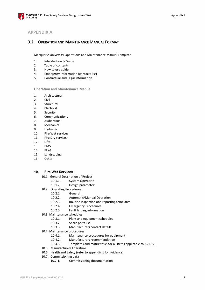
Fire Safety Services Design
MUP Fire Safety Design Standard_V1.1
APPENDIX A
3.2. OPERATION AND MAINTENANCE
Macquarie University Operations and Maintenance
1. Introduction & Guide
2. Table of contents
3. How to use guide
4. Emergency Information (contacts list)
5. Contractual and Legal information
Operation and Maintenance Manual
1. Architectural
2. Civil
3. Structural
4. Electrical
5. Security
6. Communications
7. Audio visual
8. Mechanical
9. Hydraulic
10. Fire Wet services
11. Fire Dry services
12. Lifts
13. BMS
14. FF&E
15. Landscaping
16. Other
10. Fire Wet Services
10.1. General Description of Project
10.1.1. System
10.1.2. Design parameters
10.2. Operating Procedures
10.2.1. General
10.2.2. Automatic/Manual Operation
10.2.3. Routine Inspection and reporting templates
10.2.4. Emergency Procedures
10.2.5. Fault finding information
10.3. Maintenance schedules
10.3.1. Plant and equipment schedules
10.3.2. Spare parts list
10.3.3. Manufacture
10.4. Maintenance procedures
10.4.1. Maintenance procedures for equipment
10.4.2. Manufacturers recommendation
10.4.3. Templates and matrix tasks for all items applicable to AS 1851
10.5. Manufacturers Literature
10.6. Health and Safety
10.7. Commissioning data
10.7.1. Commissioning documentation
Fire Safety Services Design Standard
AINTENANCE MANUAL FORMAT
Macquarie University Operations and Maintenance Manual Template
Emergency Information (contacts list)
Contractual and Legal information
and Maintenance Manual
General Description of Project
System Operation
Design parameters
Operating Procedures
General
Automatic/Manual Operation
Routine Inspection and reporting templates
Emergency Procedures
Fault finding information
Maintenance schedules
Plant and equipment schedules
Spare parts list
Manufacturers contact details
Maintenance procedures
Maintenance procedures for equipment
Manufacturers recommendation
Templates and matrix tasks for all items applicable to AS 1851
Manufacturers Literature
Health and Safety (refer to appendix 1 for guidance)
Commissioning data
Commissioning documentation
Appendix A
18
Templates and matrix tasks for all items applicable to AS 1851

Fire Safety Services Design Standard
MUP Fire Safety Design Standard_V1.1
10.8. Certification data
10.8.1. Certification data
10.9. Asset register (excel format) with hyperlinks to Sections 10.2, 10.3, 10.4, 10.5, 10.7, 10.8
10.10. Drawings
10.10.1. PDF
10.10.2. DWG
11. Fire Dry Services
11.1. General Description of Project
11.1.1. System
11.1.2. Design parameters
11.2. Operating Procedures
11.2.1. General
11.2.2. Automatic/Manual Operation
11.2.3. Routine Inspection and reporting templates
11.2.4. Emergency Procedures
11.2.5. Fault finding information
11.3. Maintenance schedules
11.3.1. Plant and equipment schedules
11.3.2. Spare parts list
11.3.3. Manufacture
11.4. Maintenance procedures
11.4.1. Maintenance procedures for equipment
11.4.2. Manufacturers recommendation
11.4.3. Templates and matrix tasks for all items applicable to AS 1851
11.5. Manufacturers Literature
11.6. Health and Safety
11.7. Commissioning data
11.7.1. Commissioning documentation
11.8. Certification data
11.8.1. Certification data
11.9. Asset register (excel format) with hyperlinks to Sections 11.2, 11.3, 11.4, 11.5, 11.7, 11.8
11.10. Drawings
11.10.1. PDF
11.10.2. DWG
Fire Safety Services Design Standard
Certification data
Certification data
Asset register (excel format) with hyperlinks to Sections 10.2, 10.3, 10.4, 10.5, 10.7, 10.8
DWG
General Description of Project
System Operation
Design parameters
Operating Procedures
General
Automatic/Manual Operation
Routine Inspection and reporting templates
Emergency Procedures
Fault finding information
Maintenance schedules
Plant and equipment schedules
Spare parts list
Manufacturers contact details
Maintenance procedures
Maintenance procedures for equipment
Manufacturers recommendation
Templates and matrix tasks for all items applicable to AS 1851
Manufacturers Literature
Health and Safety (refer to appendix 1 for guidance)
ioning data
Commissioning documentation
Certification data
Certification data
Asset register (excel format) with hyperlinks to Sections 11.2, 11.3, 11.4, 11.5, 11.7, 11.8
DWG
Appendix A
19
Asset register (excel format) with hyperlinks to Sections 10.2, 10.3, 10.4, 10.5, 10.7, 10.8
Templates and matrix tasks for all items applicable to AS 1851
Asset register (excel format) with hyperlinks to Sections 11.2, 11.3, 11.4, 11.5, 11.7, 11.8