Fire-resistant mortise door locks. - assaz.lv · 3 Fire-resistant mortise door locks. Page...
44
nemef.com ASSA ABLOY, the global leader in door opening solutions Fire-resistant mortise door locks. Fire-resistant mortise door locks and accessories.
Transcript of Fire-resistant mortise door locks. - assaz.lv · 3 Fire-resistant mortise door locks. Page...

nemef.com ASSA ABLOY, the global leaderin door opening solutions
Fire-resistant mortisedoor locks.
Fire-resistant mortise doorlocks and accessories.


3
Fire-resistant mortisedoor locks.
PageInformation about locks 5
Overview of the European standards for building hardware 7
Fire-resistant mortise locks 15
Special mortise locks 16
Fire-resistant mortise locks 17 Self-closing panic locks 20
Fire-resistant mortise multi-point locks 22
Fire-resistant mortise multi-point locks 24
Fire-resistant panic mortise locks for one and two leaf doors 26
Panic bar ‘Smart’ 28
Fire-resistant narrow-style panic locks 31
1900 and 3600 Series 32
Fire-resistant door handles 34
Fire-resistant door hinges 39
Fire resistant plates 40
Strike plates 41
Accessories 42
Certificates ISO 9001, EN 179 and EN 1125 43
In the future we’ll also meet the demands for technical advances and innovations. We therefore reserve the right to make designmodifications. Illustrations may thus also vary from the actual products. Despite the greatest of care, printing errors or mistakesmay be made. Nemef accepts no responsibility in such cases and will not enter into any obligations of any kind. No responsibilityis taken for the correctness of any safety regulations reproduced.
Information
EN Standards
1730 Serie
1759 Serie (non fire-resistant)
1769 Serie
1769/88 and 699
1729 and 1723 Serie
1749 and 1742 Serie
1900 Serie
3600 Serie
9670/08
Accessories
2900 Serie
1012 Serie
Fire resistant plates
Strike plates
Accessories
Certificates
Nemef guarantees an extensive and continually growing assortment of locks and builders’ hardware, such as door locks, profile cylinders, multi-point locks and access control. These quality products that leave the Nemef plant reach their customers quickly and efficiently due to a hypermodern distribution centre in the Netherlands. Nemef is working today on the standard for tomorrow through innovative product development focused on contemporary user convenience. Within this brochure we give an overview of our fire resistant mortise door locks and accessories.

4

5
Information about locks.
InternationalSituation Symbols
inside
outside
DIN Left (1) DIN Right (2)
inside
outside
DIN Left (3) DIN Right (4)
Do not fix a knob profile cylinder in lock of panic doors.
Do not fit the square spindle with force.
Do not paint front, dead- and latch bolt.
If door furniture is not fixed do not throw dead bolt. Locks must be replaced when signs of damage are obvious.
Do not leave a key in the lock of panic locks.
Do not force door trim.
Do not drill through lockcases.
6

7
Overview of the EuropeanEN Standards for building hardware.
• Resistance/reliability.• Durability.• Safety.• Ease-of-use.• Guaranteed operability.• Dimensions.• Mechanical resistance.
In public buildings• Hospital.• Shopping centre.• Station.• Airport.
In private buildings• Apartment block.• Office.
• Emergency exit devices operated by a lever handle or push pad, for use on escape routes.
• Requirements and test methods.
• Panic exit devices operated by a horizontal bar, for use on escape routes.
• Requirements and test methods.
• Locks and latches.• Mechanically operated locks, latches and
locking plates.• Requirements and test methods.
Fire-resistant door hinges. Mortise locks for fire- and smoke resistant doors.
Doorhandles for fire- and smoke resistant doors.
Mechanically operated locks, latches and panic and emergency exit devices intended for use on fire/ smoke control doors within the European Economic Area are covered by Construction Products Directive mandate issued by the European Commission. Consequently, this standard is regarded as “harmonised” and compliance with it, supported by suitable evidence, allows for the application of the CE mark.
What are the advantages of anEN-tested product?
Where do thestandards apply?
EN 179
EN 1125
EN 12209
EN 1935
DIN 18250
DIN 18273
CE marking

8
EN 179 Emergency exit devices operated by a lever handle or push pad, for use on escape routes - Requirements and test methods.
Use
Specifications for the locking mechanism for emergency exits in accordance with the EN 179 standard
Emergency situations where the occupants know the building, its escape routes and emergency exits and where panic situations are hardly to be expected; for example, in offices or apartment blocks.
The emergency exit devices in accordance with standard EN 179 are intended to ensure a safe and efficient escape route via an emergency exit door that can be opened with one simple action.
• Operation tested between -10°C and +60°C.• U-shaped lever on the inside in order to minimise
the risk of injury, and a minimum length of 120 mm (measured from the centre of the lever pivot pin to the extreme edge of the lever).
• Protrusion of the operating element: - maximum of 150 mm in category 1. - maximum of 100 mm in category 2.• The exterior means of operation (key, cylinder,
lever handle or knob) must be approved by the manufacturer of the emergency exit device.
• The force required to unlock an emergency exit device with a lever handle => less than 70 N.
• The force required to unlock an emergency exit device with a push pad (also known as pushing force) => less than 150 N.
• Durability: - 100,000 test cycles for grade 6. - 200,000 test cycles for grade 7.
High frequency of use by the public and others, where the situation may lead to rough use.
2 3
6
7
3 5
6
Cate
gory
of u
se
Dur
abili
ty
Doo
r wei
ght
100,000test cycles.
200,000test cycles.
up to 100 kg.
up to 200 kg.
1
7>200 kg.

9
Classification EN 179: 2008.
The EN 179 standard uses a 10 digit code to classify the emergency exit facility.
• Mechanical locks with a panic function and automatic locking. Lock types: e.g. Art. 1769/36, 1769/46 and 1769/88.
4 5 6 7 8 9 10
1 2 A
3 1
4
5
B
C
2
3
0 4
A
B A
B
Fire
resi
stan
ce
Safe
ty
Corr
osio
n re
sist
ance
Secu
rity
Ope
ratin
g el
emen
t
Type
of o
pera
tion
Appl
icat
ion
Maximum projection of 150 mm.
Maximum projection of 100 mm.
Not suitable for use on fire doorsand/or smoke containment doors.
Suitable for use on fire doors and smokecontainment doors (according to EN 1634-1).
Suitable for use on smoke containment doors(in accordance with the requirements specifiedin the standard).
All exit devices for emergency exit doors have a critical safety function. This standard is specially intended for this.
Very high.
High.
Note: Additional requirements for tests for a higher level of safety may not lead to a reduction relative to the other requirements in this standard.
1000 N.
2000 N.
3000 N.
5000 N.
Door lever handle.
Door lever handle/push pad.
D
Single-leaf or double-leaf door opening to the
outside: active orpassive leaf.
Single leaf dooropening to the outside.
Passive leaf of doubledoor that opens to
the outside.
Single leaf dooropening to the inside.
Classification
Nemef products that comply with theEN 179 standard

10
EN 1125 Panic exit devices operated bya horizontal bar, for use on escape routes -Requirements and test methods.
Use
Specifications for the locking mechanism for emergency exits in accordance with the EN 1125 standard.
A panic exit device (also called panic hardware) is used to allow operation of an emergency exit door in a safe, secure and efficient way, with a minimal force and without prior knowledge of the system.A panic exit device in accordance with the EN 1125 standard is used where a large number of people can be expected who, in an emergency situation, are neither familiar with the escape routes nor the escape provisions.
Consequently, it offers a safe way of escaping the building even when the door is subjected to load (i.e. even when a person pushes against the door and not on the bar, one should still be able to open the door by pressing the panic bar). The panic exit devices are opened by a horizontal bar.There are two types:- Type A, panic exit devices with a push bar: the bar
moves through an arc in the downward direction.- Type B, panic exit devices with a touch bar: this is a
bar which is pushed in the direction of opening.
Panic exit devices are available as complete face-fit units or as face fit units in combination with a mortise lock. The exterior face to exterior face dimension of a panic exit device must match the total door width as accurately as possible, but may never be less than 60% of the total door width.
• Operation tested between -10°C and +60°C.• All sharp edges must be rounded to a minimum
radius of 0.5 mm.• The distance between the bar and the door leaf
surface may not be less than 25mm.• Protrusion of the operating element: - maximum of 150 mm in category 1. - maximum of 100mm in category 2.• The exterior means of operation (key, cylinder,
lever handle or knob) must be approved by the manufacturer of the panic exit device.
• The force required for unlatching a panic exit device in a situation where the door is not under load => less than 80 N.
• The force required for unlatching a panic exit device in a situation where the door is under load => less than 220 N.
• Durability: - 100,000 test cycles for grade 6. - 200,000 test cycles for grade 7.
2 3
6
7
3 5
6
7
Cate
gory
of u
se
Dur
abili
ty
Doo
r wei
ght
High frequency of use by the public and others, where the situation may lead to rough use.
Up to 100 kg.
Up to 200 kg.
>200 kg.
1
100,000test cycles.
200,000test cycles.

11
Classification EN 1125: 2008.
The EN 1125 standard uses a 10 digit code to classify the emergency exit facility.
All face-fit panic bar exit devices in the Nemef range comply with the EN 1125 standard.
The panic bar exit devices with integral lock (tested together) that comply with the EN 1125 standard are:Lock types: e.g. Art. 1901 and 1921.On condition that the exit can always be used via the lever handle on the inside, the norm does not allow monitoring of the exit.
Classification
Nemef products that comply with theEN 1125 standard
4 5 6 7 8 9 10
1 2 A
1
B
2
3 C
0 4
A
B A
B
Fire
resi
stan
ce
Safe
ty
Corr
osio
n re
sist
ance
Secu
rity
Ope
ratin
g el
emen
t
Ope
ratio
n ty
pe
Appl
icat
ion
All exit devices for emergency exit doors have a critical safety function. This standard is specially intended for this.
The horizontal push rod/bar can
withstand a force of 1000 N (100 kg).
Single-leaf ordouble-leaf door:
active or passive leaf.
Maximum projection of 150mm.
Note: Additional requirements for tests for a higher level of safety may not lead to a reduction relative to the other requirements in this standard.
Single-leaf door.
Not suitable for use on fire doors and/or smoke containment doors.
Very high (240 hour salt spray test).
Suitable for use on fire doors and smokecontainment doors (according to EN 1634-1). Push rod.
High (96 hoursalt spray test).
Passive leaf ofa double door.
Suitable for use on smoke containmentdoors (in accordance with the requirements specified in the standard).
Push bar.
Maximum projection of 100 mm.

12
EN 12209 Locks and latches - Mechanicallyoperated locks, latches and locking plates -Requirements and test methods.
Use
Specifications for the locking mechanism for emergency exits in accordance with theEN 12209 standard.
Classification
Nemef productsthat comply with theEN 12209 standard
This European standard specifies the requirements and test methods for durability, resistance, security, operation of the mechanical locks and their locking plates in accordance with the usage profile for the door. The correct grade must be chosen in line with the usage profile.
• Operation tested between -20°C and +80°C.• Category of use: - Grade 1: average frequency of use, very careful
users => private use. - Grade 2: high frequency of use, careful users =>
interior doors in offices. - Grade 3: very high frequency of use, high
probability of abuse => offices in public buildings.
• Durability: in accordance with the cycles and load on the day latch.
• Fire resistance: - Grade 0: not CF-approved. - Grade 1: CF-approved.• Safety.• Corrosion resistance.• Security.
The EN 12209 standard uses an 11 digit code to classify the mechanical locks.
Mechanical locks with a panic function and automatic locking.
1 2 3
A 1
B 2
C 3
F 4
G 5
H 6
L 7
M 8
R 9
S
W
X
1
2
3
Cate
gory
of u
se
Dur
abili
ty a
nd lo
ad o
n th
e da
y la
tch
Doo
r wei
ght a
nd c
losi
ng
forc
e
Low risk of abuse, verycareful users=>PRIVATE USE.
50,000 cycles,no load.
100,000 cycles, no load.
200,000 cycles,no load.
50,000 cycles,10 N load.
200,000 cycles,10 N load.
200,000 cycles,25 N load.
200,000 cycles,50 N load.
100,000 cycles,10 N load.
100,000 cycles,25 N load.
100,000 cycles,50 N load.
100,000 cycles,120 N load.
200,000 cycles,120 N load.
Up to 100 kg,50 N maximum.
Up to 200 kg,50 N maximum.
Up to 100 kg,25 N maximum.
More than 200 kgor as indicated,25 N maximum.
Up to 200 kg,15 N maximum.
More than 200 kgor as indicated,50 N maximum.
Up to 200 kg,25 N maximum.
Up to 100 kg,15 N maximum.
More than 200 kgor as indicated,15 N maximum.
Risk of abuse, careful users=>OFFICES.
High frequency of use by thepublic, with a high risk of abuse => PUBLIC BUILDINGS.

13
Classification EN 12209: 2003/AC: 2005.
4 5 6 7 8 9 10 11
0 1 A 0 0
A 2 B A A
B 3 C B B
C 4 D C C
D 5 E D
DE 6 F E
EF 7 G F
F
G H G
G
J H
H
0 K
0 L
M
1 N 0
P 1
R 2
3
4
Fire
resi
stan
ce
Safe
ty
Corr
osio
n re
sist
ance
and
te
mpe
ratu
re re
sist
ance
Secu
rity:
resi
stan
ceto
att
ack
usin
g a
drill
Area
of a
pplic
atio
nof
the
door
Type
of k
ey o
peni
ng:
latc
h m
echa
nism
Type
of s
quar
e sh
aft
Iden
tifica
tion
of th
e ke
y
Minimal; no resistance.
Mortise lock;without limitationon the application.
Not applicable. No requirements.
Weak; no resistance.
Mortise lock; hinged door.
Cylinder lock; manual.
At least 3 locking pins.
Average;no resistance.
Mortise lock;sliding door.
Cylinder lock; automatic. At least 5 locking pins.
High;no resistance.
Very high;no resistance.
Face-fit lock; sliding door.
Lever lock;automatic.
With knob or sprung lever.
At least 6 locking pins with an extensive number
of combinations.
Face-fit lock; hinged door, latch on interior face.
Mortise lock;hinged door;supported.
Lock withoutkey; manual.
With unsprung leverfor intensive use.
At least 7 locking pinswith an extensive number
of combinations.
Mortise lock; hinged door;supported, latch on interior face.
High; with resistance.
Face-fit lock;hinged door. Lever lock; manual.
Lock without lock shaft aperture.
At least 6 locking pins.
Very high;with resistance.
Mortise lock;without limitationon the application.
Lever lock; manual with intermediary.
With unsprung lever.
At least 7 locking pins .
Face-fit lock; sliding door, latch on interior face.
Face-fit lock; hinged door, opening tothe exterior.
Lock with night latch without key; automatic.
With sprung lever for intensive use indicated by the manufacturer.
At least 8 locking pinswith an extensive number
of combinations.
Face-fit lock; hinged door, opening to the interior, latch on interior face.
Mortise lock; hingeddoor, latch on interior face.
No requirements
Not suitable for use on fire doors and/or smoke containment doors.
Suitable for use on fire doors and/or smoke containment doors.
No requirements.
Low resistance; no requirements.
Average resistance; no requirements.
High resistance; no requirements.
Very high resistance;no requirements.
Average resistance; between -20°Cand +80°C.
High resistance; between -20°C and +80°C.
Very high resistance; between -20°Cand +80°C.
Mortise lock; sliding door, latch on interior face.
Face-fit lock;without limitation on the application.
Cylinder lock; manual with intermediary.
At least 3 locking pins with an extensive number
of combinations.

14

15
Art. 1739
1730 Series.Fire-resistant mortise locks
Art. 1739/36
Art. 1739/46
Accessories
• For European profile cylinder.• Key action on latch bolt.• Single throw dead bolt.• Non-handed.• Without strike plate.
Furniture with fixed knob outside is required.In unlocked position latch bolt retracts from the outside only by key action, from the inside by lever handle. In locked position lever handle retracts latch- and dead bolt simultaneously from inside (panic function). Bolts operated from outside by cylinder key only.
Furniture with split spindle is required.In unlocked position, latch bolt is operated from both sides by lever handle/key action. In locked position, inside lever handle retracts latch-and dead bolt simultaneously. Outside lever handle retracts latch bolt only. Dead bolt operated by cylinder key.
• Key-infill piece with set screw Art. BB 1739 and BB 7000 (Page 42).
• Strike plate Art. P 1739/17 stainless steel and 1739/12 zinc-plated (page 41).
• Reduction sleeve 8/9 mm Art. 1769/21 (page 42).
1739
/03
1739
/27
1739
/28
1739
/29
1739
/36
1739
/46
1739
/51
1739
/55
Backset 65 mm • • • • • • • •Distance 72 mm • • • • • • •Profile cylinder • • • • • • •9 mm follower • • • • • • • •Steel, zinc-plated front plate 24 x 235 mm rounded • • • • • • •Stainless steel front plate 24 x 235 mm rounded •Steel, zinc-plated lock case • • • • • • • •Steel, zinc-plated latch bolt • • • • • • •Zinc-plated roller bolt (adjustable) •Steel, zinc-plated dead bolt • • • • • • •Key action on latch bolt • • • • • • • •Single throw • • • • • • • •Panic one-piece follower •Panic two-piece follower •Zinc-plated security bolt •22 mm profile cylinder •Packed per piece • • • • • • •Packed per 25 pieces •
Specifications
Art. 1739Standards: CE marking, EN 12209 andEN 179 (Panic)

16
Art. 1759Standards: none
Art. 1759
Accessories
Note
• Non fire-resistant.• For European profile cylinder.• Key action on latch bolt.• Single throw dead bolt.• Non-handed.• Without strike plate.
Strike plate Art. P1759/02 steel zinc plated(page 41).
For non fire-resistant steel doors (for example passage door in garage).
1759 Series (non fire-resistant).Special mortise locks.
1759
/02
1759
/02
KABA
1759
/06
1759
/08
1759
/08
KABA
1759
/26
1759
/29
Backset 65 mm • • • • • • •Distance 72 mm • • • • •Profile cylinder • • • • •8 mm follower • • • • • • •Steel, lacquered front plate 20 x 235 mmrounded RAL 7035 • • •Steel, zinc-plated front plate 20 x 235 mm rounded • •Steel, zinc-plated front plate 20 x 325 mm roundedHole 6.5 countersunk 11.25 x 90˚ • •Steel, zinc-plated lock case for multi-point •Steel, zinc-plated lock case • • • • • •Die-cast, latch bolt • • • • • • •Latch bolt not centric in front plate • • •Die-cast, dead bolt • • • • • • •Key action on latch bolt • • • • • • •Single throw • • • • • • •22 mm profile cylinder • •Handed •Packed per piece • •Packed per 25 pieces • • • • • • •
Specifications

17
Art. 1769/03
• For European profile cylinder.• Key action on latch bolt.• Double throw dead bolt.• Handed.• Without strike plate.
Furniture with fixed knob outside is required.In unlocked position latch bolt retracts from the outside only by key action, from the inside by lever handle. In locked position lever handle retracts latch- and dead bolt simultaneously from inside (panic function E). Bolts operated from outside by cylinder key only.
Furniture with split spindle is required. In unlocked position, latch bolt is operated from both sides by lever handle/key action. In locked position, inside lever handle retracts latch- and dead bolt simultaneously (panic function D). Outside lever handle retracts latch bolt only. Dead bolt operated by cylinder key.
1769 Series.Fire-resitant mortise locks.
Art.1769/36
Art.1769/46
1769
/03
1769
/08
1769
/23
1769
/24
1769
/25
1769
/26
1769
/32
1769
/35
1769
/36
1769
/46
1769
/48
1769
/56
1769
/57
1769
/77
Backset 65 mm • • • • • • • • • • • • • •Distance 72 mm • • • • • • • • • • • • • •Profile cylinder • • • • • • • • • • • • • •9 mm follower • • • • • • • • • • • •8 mm follower •Steel, zinc-plated front plate24 x 235 mm rounded • • • • • •Stainless steel front plate24 x 235 mm rounded • • • • • •Stainless steel front plate20 x 235 mm rounded • •Steel, zinc-plated lock case • • • • • • • • • • • • • •Steel, zinc-plated latch bolt • • • • • •Steel, nickel-plated latch bolt • • • • • • •Steel, zinc-plated dead bolt • • • • • •Steel, nickel-plated dead bolt • • • • • • •Latch only •Dead bolt only •Key action on latch bolt • • • • • • • • • • • • •Double throw • • • • • • • • • • • • •Panic one-piece follower • •Panic two-piece follower • • • • •Panic two-piece follower inwards •Lever free •Packed per piece • • • • • • • • • • • •Packed per 25 pieces • •
Accessories: 22 mm profile cylinder hole, strike plate Art. P 1769/66 zinc-plated(reversible) or Art. P 1769/17 stainless steel (handed) (page 41), reduction sleeve 8/9 mmArt. 1769/21 (page 42).
Specifications
Art. 1769Standards: CE marking, EN 12209, EN 1125, EN 179 (panic) and DIN 18250 T 120 (part 1)

18

19
Art. 1769/01 and 1769/02Standards: CE marking, EN 12209 and DIN 18250 T 120 (part 1)
Art. 1769
* Class 5 according to DIN 18250 attachment 2.
1769 Series - Class 5*.Fire-resistant mortise locks.
• For fire-resistants doors.• To take profile cylinder.• Handed.• Backset 65 mm - distance 72 mm.• Key action on latch bolt.• Plastic latch for noise reduction.• Double throw Omega dead bolt.• Front plate available in 20/24 mm in
aluminium finish or stainless steel.• Available with plastic dead bolt cap on request.• Without strike plate.
1769
/01
1769
/02
Front plate 20 x 235 mm rounded •Front plate 24 x 235 mm rounded •9 mm follower • •Aluminium finish or stainless steel • •Packed per 25 or 750 pieces • •
Specifications

20
1769/88 Selbstschliessende Panikschlösser.Feuerhemmend.
Attention
Accessories
Art. 1769/88
Art. 1769/88Standards: EN 179 and DIN 18250 T 120 (part 1), MPA registered
1769/88 Self-closing Panic locks.Fire-resistant.
• To take profile cylinder.• Handed.• Backset 65 mm - distance 72 mm.• Key action on latch bolt.• With auxiliary latch.• 9 mm bolt through follower.• Is fire-resistant and MPA registered.• Without strike plate.
Do not use these locks in combination withknob cylinder, electrical door opener nor lever/lever handle.
None.
1769
/88
Backset 65 mm •Stainless steel front plate 20 x 235 mm rounded •Stainless steel front plate 24 x 235 mm rounded •Packed per piece •
Specifications

21
Attention
Accessories
Art. 699
Art. 699Standards: EN 179
Specifications
699 Self-closing Panic locks.Non fire-resistant.
• To take profile cylinder.• Handed.• Backset 55 und 60 mm - distance 72 mm.• Key action on latch bolt.• With auxiliary latch.• 8 mm bolt through follower.• Including strike plate.
Do not use these locks in combination withknob cylinder, electrical door opener nor lever/lever handle.
None.69
9/30
699/
31
699/
34
699/
35
Backset 55 mm • •Backset 60 mm • •Stainless steel front plate 20 x 235 mm rounded • •Stainless steel front plate 24 x 235 mm rounded • •Packed per piece • • • •

22
1729 and 1723 Series.Fire-resistant mortise multi-point locks.
Lower lock Art. 1723/21Standards: none
Upper lock Art. 1723/21Standards: none
Main lock Art. 1729/21 Standards: none
Rod Art. 1729Standards: none

23
THR
OW
THR
OW
• Non-handed.• For European profile cylinder.• Key action on latch bolt.• Single throw dead bolt.• With rod movement up- and downwards.• Without strike plate.
• Handed.• With rod connection.
Length 648 or 958 mm.
Latch bolts are operated from both sides by lever handle or key action on latch bolt.
Dead bolt is locked. Latch bolts are operated from both sides by lever handle.
None.
1729 and 1723 Series.Fire-resistant mortise multi-point locks.
Main lockArt. 1729/21
LatchesArt. 1723/21
RodsArt. 1729
In unlocked position
In locked position
Accessories
1729
/21
1723
/21
Backset 65 mm •Distance 72 mm •Profile cylinder •9 mm follower •Steel, zinc-plated front plate 24 x 288 mm rounded •Steel, zinc-plated front plate 24 x 197 mm rounded •Zinc-plated lock case • •Zinc-plated latch bolt • •Zinc-plated dead bolt •Key action on latch bolt •Packed per 25 pieces • •
Specifications
Art. 1729/21 and 1723/21 (2x)

24
1749 and 1742 Series.Fire-resistant mortise multi-point locks.
Lower lock Art. 1742/09Standards: CE marking and DIN 18250 T120(Part 1)
Upper lock Art. 1742/09Standards: CE marking and DIN 18250 T120(Part 1)
Main lock Art. 1749Standards: CE marking and DIN 18250 T120(Part 1)
Rod Art. 1742

25
1749 and 1742 Series.Fire-resistant mortise multi-point locks.
Art. 1749 und 1742/09 (2x)
THR
OW
THR
OW
• Handed.• For European profile cylinder.• Key action on latch bolt.• Double throw dead bolt.• With rod movement up- and downwards.• Without strike plate.
• Non-handed.• With adjustable rod application.
Length 629, 689, 754 or 879 mm.
Latch bolt is operated from both sides by lever handle/key action.
Dead bolt and pivot dead bolts are locked. Latch bolt and lever handle are blocked.
Please use Art. 1742 only in accordance withArt. 1749/09, 1749/37 and 1749/47.
None.
Main lockArt. 1749
Pivot dead boltsArt. 1742/09
RodsArt. 1742
In unlocked position
In locked position
Note
Accessories
1749
/09
1749
/37
1749
/47
1742
/09
Backset 65 mm • • •Distance 72 mm • • •Profile cylinder • • •9 mm follower • • •Steel, zinc-plated front plate 24 x 235 mm rounded • • • •Steel, zinc-plated lock case • • • •Steel, zinc-plated latch bolt • • •Steel, zinc-plated dead bolt • • • •Key action on latch bolt • • •Panic one-piece follower E •Panic two-piece follower D •Suitable for fixed rods • • • •Packed per 25 pieces • • •Packed per 50 pieces •
Specifications

Art. 1901/21
26
• For European profile cylinder.• Key action on latch bolt.• Two-piece follower.• Without strike plate.
• Panic lock for active leaf.• Non-handed.
• Narrow style panic lock for active leaf.• Handed.
• Multi-point panic lock for active leaf.• Handed.
Latch bolt is operated from both sides by lever handle/key action.
No operation of latch bolt from outside. Operation latch bolt from inside handle.
Art. 1901/17 is the same lock, however the forend is stainless steel.
Art. 1901 certified according to EN 1125.
See pages 28, 29, 32 and 33.
1901 and 1905 Series.Fire-resistant panic mortise locks for active leaf.
Art. 1901
Art. 1905/21
Art. 1929/21
In unlocked position
In locked position
Note
Accessories
1901
/17
1901
/21
1905
/21
1929
/21
Backset 65 mm • • •Backset 40 mm •Distance 72 mm • • • •Profile cylinder • • • •9 mm follower • • • •Steel, zinc-plated front plate 24 x 235 mm rounded •Steel, zinc-plated front plate 24 x 350 mm rounded •Stainless steel front plate 24 x 235 mm rounded •Steel, zinc-plated front plate 24 x 288 mm rounded •Steel, zinc-plated lock case for multi-point lock •Steel, zinc-plated lock case • • • •Die-cast, zinc-plated latch bolt • • • •Key-action on latch bolt • • •Non-handed • •Handed • •Packed per 25 pieces • • • •
Specifications
Art. 1901Standards Art. 1901: CE marking, EN 1125 and EN 12209 Standards Art. 1905 and 1929: none

27
Art. 1921/21
1920, 1921 and 1925 Series.Fire-resistant panic mortise locks for passive leaf.
• Panic lock for passive leaf.• Handed.
• Art. 1921/17 and /21 panic lock for passive leaf.• Non-handed.
• Art. 1925/21 narrow style panic lock for passive leaf.
• Handed.
By operating the inside lever handle the upper and lower rods are retracted and the latch bolt in the active lock (Art. 1901/21 and 1905/21) pushed back, which opens both doors.
The rods are held in unlocked position by the automatic relatching device. When closing the passive door, the rods are brought back in locked position automatically.
Upper and lower rod can not be operated simultaneously.
Do not use lever handle from outside on Art. 1920, 1921 and Art. 1925.
See pages 28, 29, 32 and 33.
Art. 1920/21
Art. 1921
Art. 1925
Function
In unlocked position
In locked position
Accessories
1920
/21
1921
/17
1921
/21
1925
/21
Backset 65 mm • •Backset 40 mm •Backset 95 mm •9 mm follower • • • •Steel, zinc-plated front plate 24 x 235 mm rounded • •Steel, zinc-plated front plate 24 x 350 mm rounded •Stainless steel front plate 24 x 235 mm rounded •Steel, zinc-plated lock case • • • •Non-handed • •Handed • •Packed per piece •Packed per 25 pieces • • • •
Art. 1921Standards Art. 1921: EN 1125Standards Art. 1920 and 1925: none
28
Aluminium rod Art. 3630/4
ADJUSTABLE
ADJUSTABLE
Art. 3640/1 and 3640/17
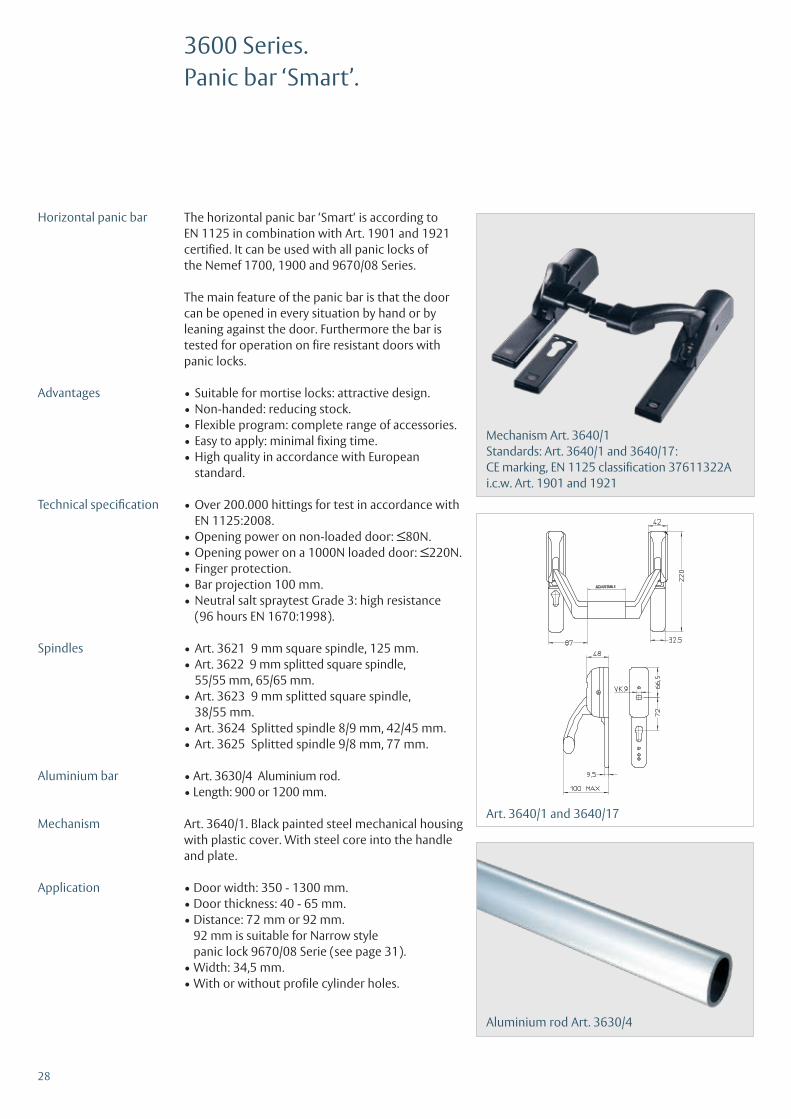
The horizontal panic bar ‘Smart‘ is according toEN 1125 in combination with Art. 1901 and 1921 certified. It can be used with all panic locks ofthe Nemef 1700, 1900 and 9670/08 Series.
The main feature of the panic bar is that the door can be opened in every situation by hand or by leaning against the door. Furthermore the bar is tested for operation on fire resistant doors with panic locks.
• Suitable for mortise locks: attractive design.• Non-handed: reducing stock.• Flexible program: complete range of accessories.• Easy to apply: minimal fixing time.• High quality in accordance with European
standard.
• Over 200.000 hittings for test in accordance with EN 1125:2008.• Opening power on non-loaded door: ≤80N.• Opening power on a 1000N loaded door: ≤220N.• Finger protection.• Bar projection 100 mm.• Neutral salt spraytest Grade 3: high resistance
(96 hours EN 1670:1998).
• Art. 3621 9 mm square spindle, 125 mm.• Art. 3622 9 mm splitted square spindle,
55/55 mm, 65/65 mm.• Art. 3623 9 mm splitted square spindle,
38/55 mm.• Art. 3624 Splitted spindle 8/9 mm, 42/45 mm.• Art. 3625 Splitted spindle 9/8 mm, 77 mm.
• Art. 3630/4 Aluminium rod.• Length: 900 or 1200 mm.
Art. 3640/1. Black painted steel mechanical housing with plastic cover. With steel core into the handle and plate.
• Door width: 350 - 1300 mm.• Door thickness: 40 - 65 mm.• Distance: 72 mm or 92 mm.
92 mm is suitable for Narrow style panic lock 9670/08 Serie (see page 31).
• Width: 34,5 mm.• With or without profile cylinder holes.
3600 Series.Panic bar ‘Smart’.
Horizontal panic bar
Advantages
Technical specification
Spindles
Aluminium bar
Mechanism
Application
Mechanism Art. 3640/1Standards: Art. 3640/1 and 3640/17:CE marking, EN 1125 classification 37611322Ai.c.w. Art. 1901 and 1921

29
Mechanism Art. 3650/1Standards: none
Stainless steel rod Art. 3630/17
Mechanism Art. 3640/17(see Standards 3640/1)
Connecting rods Art. 3645
3600 Series.Panic bar ‘Smart’.
• Art. 3630/17, Stainless steel rod.• Length: 900 or 1200 mm.
Art. 3640/17. Stainless steel mechanical housing.With steel core into the handle and plate.
• Door width: 350 - 1300 mm.• Door thickness: 40 - 65 mm.• Distance: 72 mm or 92 mm.
92 mm is suitable for Narrow style panic lock 9670/08 Serie (see page 31).
• Width: 34,5 mm.• With or without profile cylinder holes.
• Art. 3630/4, Aluminium rod.• Length: 900 or 1200 mm.
• Art. 3645/1, black painted connecting rods.• Art. 3650/1, black painted mechanical housing
with plastic cover. With steel core into the handle and plate.
• Door width: 350 - 1300 mm.• Non-handed.• Can only be used for double leaf doors in
combination with the Smart version.
Stainless steelbar ‘Smart’
Mechanism
Application
Rim-type
Bar
Mechanism
Application

9600 Series.Fire-resistant narrow-style lock.
Accessories
• To take profile cylinder.• Key action on latch bolt.• Backset 30, 35 and 40 mm.• Distance 92 mm.• Single throw dead bolt.• Latch reversible.• Follower 9 mm MPA registered.• Without strike plate.
Strike plate P9600/17 stainless steel (page 41).
9600
/08
Backset 30, 35 and 40 mm •Distance 92 mm •To take profile cylinder •Stainless steel front plate 24 x 245 mm square •Steel, zinc-plated lock case •Key action on latch bolt •Single throw •9 mm follower MPA registered •Packed per piece • Art. 9600/08
Art. 9600/08 fire-resistantStandards: EN 12209
Specifications
30

31
Accessories
9670
/08
Backset 30, 35, 40 and 45 mm •Distance 92 mm •To take profile cylinder •Stainless steel front plate 24 x 245 mm square •Steel, zinc-plated lock case •Key action on latch bolt •Single throw •Panic one-piece follower, E •Panic two-piece follower, D •Packed per piece • Art. 9670
Art. 9670Standards: CE marking and EN 179
• To take profile cylinder.• Key action on latch bolt.• Backset 30, 35, 40 and 45 mm.• Distance 92 mm.• Single throw dead bolt.• One-piece follower, latch reversible.• Two-piece follower, handed.• Follower 8 or 9 mm.• Follower 9 mm MPA registered.• Without strike plate.
Strike plate P9600/17 stainless steel (page 41).
9670 Series.Fire-resistant narrow-style panic lock.
Specifications

32
Accessories1900 and 3600 Series.
Art. 1935Automaticrelatching device
Art. 1936Rod hasp bottom
Art. 1937Rod hasp top
Art. 1938Strike plate forArt. 1901
Art. 1939Floor strike cup

33
Accessories1900 and 3600 Series.
Art. 1932Zinc-plated rods with two closing boltsLength: 1200 mm
Art. 1995Flush bolt to be used for passive door and to combine with Art. 1932
Example use ofArt. 1932 and 1935

34
Art. 2914
• Back plate: Steel.• Cover plate: Plastic, black or aluminium look.• Handle: Plastic, black or aluminium look,
fixed to plate.• Square spindle: 9 mm.• Door width: 40 - 63 mm.• Art. 2914/02: Lever/lever blind mat black.• Art. 2914/12: Lever/lever blind aluminium look.
2914 Series.Fire-resistant door handle.
Art. 2914
Art. 2914/02Standards: DIN 18273

35
Art. 2916
Art. 2916
• Back plate: Steel.• Cover plate: Plastic, black, grey, white,
aluminium look or stainless steel.• Handle: Plastic, black, grey, white, aluminium
look and stainless steel, fixed to plate.• Square spindle: 9 mm.• Door width: 40 - 63 mm.• Distance: 72 mm.• Art. 2916/02: Lever/lever black.• Art. 2916/05: Lever/lever grey.• Art. 2916/07: Lever/lever white.• Art. 2916/12: Lever/lever aluminium look.• Art. 2916/13: Lever/lever stainless steel.
Also available in non fire-rated execution (without steel plate), Art. 2959/02 (page 38).
2916 Series.Fire-resistant door handle.
Art. 2916/02Standards: DIN 18273
36
Art. 2919
2919 Series lever/knob panic handle.Fire-resistant door handle.
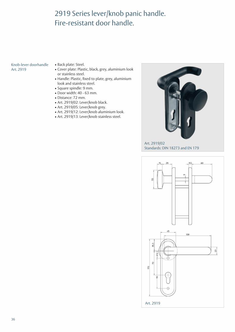
• Back plate: Steel.• Cover plate: Plastic, black, grey, aluminium look
or stainless steel.• Handle: Plastic, fixed to plate, grey, aluminium
look and stainless steel.• Square spindle: 9 mm.• Door width: 40 - 63 mm.• Distance: 72 mm.• Art. 2919/02: Lever/knob black.• Art. 2919/05: Lever/knob grey.• Art. 2919/12: Lever/knob aluminium look.• Art. 2919/13: Lever/knob stainless steel.
Knob-lever doorhandleArt. 2919
Art. 2919/02Standards: DIN 18273 and EN 179

37
Art. 2924
• Back plate: Steel.• Cover plate: Plastic, black.• Handle: Plastic, black, fixed to plate.• Square spindle: 9 mm splitted.• Door width: 40 - 63 mm.• Distance: 72 mm.• Art. 2924/02: Lever/lever black.
2924 Series lever/lever panic handle.Fire-resistant door handle.
Lever handlepanic furnitureArt. 2924
Art. 2924/02Standards: DIN 18273 and EN 179

38
Art. 2959/02
• Plate: Black plastic.• Handle: Black plastic.• Square spindle: 8 mm.• Door width: 40 - 63 mm.• Distance: 72 mm.• Art. 2959/02: Lever/lever black.
Art. 2959/02(non fire-resistant)
Art. 2959/02Standards: none
2959 Series.Non fire-resistant door handle.

39
Art. 1012/02
Fire-resistant door hinges. Zinc-plated finish.
Set consisting of:• One spring hinge.• One non-spring hinge.• Fixing pin.• Fixing screw.
Art. 1012/02
1012 Series.Fire-resistant door hinges.
Art. 1012/02Standards: EN 1935

40
Art. 2930/02 black 72 mmStandards: none
Art. 2931/02 black 72 mmStandards: none
Art. 2932/02 blackStandards: none
Art. 2933/02 blackStandards: none
Art. 2934/02 blackStandards: none
Art. 2935/02 blackStandards: none
Art. 2936/02 blackStandards: none
Fire resistant plates.

41
* Standards: for strike plates are no standards.
Strike plates*.
Art. P 1739/12, steel zinc-plated, non-handed
Art. P 1739/17, stainless steel, non-handed
Strike plates 1760 SeriesFor the 1760 and 1740 series the following strike plates can be used:
Strike plates 1730 seriesFor the 1730 and 1901 series the followingstrike plates can be used:
Strike plate 1759 SeriesFor the 1759 series the following strikeplate can be used:
Art. P 1759/02, steel zinc-plated, non-handed
Art. P 1769/66,steel zinc-plated,non-handed
Art. P 1769/17,stainless steel,handed
Strike plate 9600 SeriesFor the 9600 Series
Art. P 9600/17 Stainless steel,non-handed

42
Accessories.
Art. BB7000BB infill piece with 1 key
Art. BB1739BB infill piece with 1 key
Art. 1769/21Reducing sleeve 8/9 mm

M A T E R I A L P R Ü F U N G S A M T N O R D R H E I N - W E S T F A L E N
DIESES ZERTIFIKAT UMFASST 1 SEITE UND 3 ANLAGEN.
Marsbruchstraße 186 44287 Dortmund-Aplerbeck Telefon (0231) 4502-480 Telefax (0231) 4502 586 Internet www.mpanrw.de
EG–KONFORMITÄTSZERTIFIKAT 0432 – CPD – 0038
Gemäß der Richtlinie des Rates der Europäischen Gemeinschaften vom 21. Dezember 1988 zur Angleichung der Rechts– und Verwaltungsvorschriften der Mitgliedstaaten über Bauprodukte (Bauproduktenrichtlinie – CPD), geändert durch die Richtlinie 93/68/EWG des Rates der Europäischen Gemeinschaften vom 22. Juli 1993, wird hiermit bestätigt, dass das Bauprodukt
Notausgangsverschlüsse NEMEFNotausgangstürverschlüsse mit Drücker für 1flügelige Türen
gemäß der Zusammenstellung und Klassifikation in der Anlage 2,
in Verkehr gebracht durch
NEMEF BV Papegaaiweg 35
NL-7345 DK Wenum Wiesel
und hergestellt in den Herstellwerken
gemäß Anlage 1 durch den Hersteller einer werkseigenen Produktionskontrolle sowie zusätzlichen Prüfungen von im Werk entnommenen Proben nach festgelegtem Prüfplan unterzogen werden und dass die notifizierte Stelle Nr. - 0432 - MPA NRW – eine Erstprüfung der relevanten Eigenschaften des Produkts, eine Erstinspektion des Werkes und der werkseigenen Produktionskontrolle durchgeführt hat und eine laufende Überwachung, Beurteilung und Anerkennung der werkseigenen Produktionskontrolle durchführt. Dieses Zertifikat bestätigt, dass alle Vorschriften über die Bescheinigung der Konformität und die Leistungseigenschaften, beschrieben im Anhang ZA der Norm
DIN EN 179: 2008-04 (EN 179: 2008 (D))
angewendet wurden und dass das Produkt alle darin vorgeschriebenen Anforderungen erfüllt. Dieses Zertifikat wurde erstmals am 15.04.2011 ausgestellt und gilt solange, wie die Festlegungen in der angeführten harmonisierten technischen Spezifikation oder die Herstellbedingungen im Werk oder die werkseigene Produktionskontrolle selbst nicht wesentlich verändert werden.
Dortmund, 15.04.2011
Dip.-Ing. H. Jansen stellv.Leiter der Zertifizierungsstelle
If you require more information about the certificates or the combination of different locks with panic exit devices, please contact us.
* Certificates can be downloaded from our website www.nemef.com.
43
Certificates*ISO 9001, EN 179 and EN 1125.

ASSA ABLOY is the globalleader in door opening solutions, dedicated to satisfyingend-user needs for security,safety and convenience.
ASSA ABLOY Nederland B.V.Business Unit NemefP.O. Box 137300 AA ApeldoornThe NetherlandsTel. +31 55 3128400 Fax +31 55 [email protected]
9999990351 / JTP - 06/2012